front end assembly
TRANSCRIPT

IMPORTANT
Read these instructions completely before installing, using or attempting to repair this product. If you have any questions,
call Premier at (800) 255-5387 or (503) 234-9202.
Installation, Inspection, Operation & Maintenance Guide
MANUFACTURING CO.THE FIRST NAME IN QUALITY COUPLINGS
Model 340S / 340SAFront End Assembly

premier manufacturing company 1-800-255-5387 • www.premier-mfg.comPage 2
Selecting The Right Equipment
Step 4: Browse Premier Product Catalog
Step 3: Considering Operating Conditions and Environments
Step 2: Determine “Tongue Weight Capacity”
Step 1: Determine “Gross Trailer(s) Weight”
Whatever your application, selecting the proper equipment for the job is very important. Proper selection along with regular inspection and maintenance will help keep operating costs minimal while providing long life to each component. Below are general guidelines for selecting Premier Couplings and Drawbar Eyes. If you feel that your application is unique, please give Premier a call so that we may help you through the selection process.
Follow these four steps to ensure proper selection of Premier Couplings and Drawbar Eyes.
Step 2:Determine “TongueWeight Capacity”
(Maximum occurring tongue weight)
Step 3:Add Margin of Safety
(Dependent upon your equipment and operating environment)
Step 4:Browse Premier Product Catalog(Based on Steps 1 - 3)
Step 1:Determine “Gross Trailer(s) Weight”
(GVWR(s) of towed trailers)
“Gross Trailer(s) Weight” is usually determined by the Gross Vehicle Weight Rating (GVWR). This information is attached to the trailer by the trailer manufacturer.
For “Double Trailer” configurations, only the rear trailer is considered when selecting your Premier Coupling or Drawbar Eye. In this example, a Coupling and Drawbar Eye with a “Gross Trailer Weight” rating of 40,000 lbs. (18,143 kg) would be the minimum rating acceptable for normal, over-the-road applications (see Tongue Weight section below).
For “Triple Trailers”, only the two most rearward trailers are considered in selecting your Premier Coupling or Drawbar Eye. In this example, a Coupling and Drawbar Eye with a “Gross Trailer Weight” rating of 80,000 lbs. (36,287 kg) would be the minimum acceptable for normal, over-the-road applications (see Tongue Weight section below).
Double Trailer Configuration
Triple Trailer Configuration
Example only, each application may vary and should be considered unique.
Example only, each application may vary and should be considered unique.
40,000 LBS 40,000 LBS
40,000 LBS
Environments such as rough uneven roads or off-road use can dramatically increase shock loads to both drawbar eyes and couplings. In general, increasing the “Gross Trailer Weight” (Step 1:) and “Tongue Weight Capacity” (Step 2:) by a minimum of 25% will be sufficient for many applications. Even if an application is used off-road occasionally, the minimum increase necessary for Gross Trailer and Tongue Weight is 25%. Certain types of equipment and/or operating practices can also dramatically increase loads through equipment binding and/or improper loading practices. Of special concern is high tongue weight. However, each application is unique and every environment different, therefore your application may require more than 25%.
Once both “Gross Trailers(s) Weight” (Step 1:) and “Tongue Weight Capacity” (Step 2:) have been determined, evaluate your operating conditions and apply an appropriate margin of safety.
Browse the Premier Product Catalog and refer to the “Specifications” section of each product. Be sure to review the “Understanding Premier Load Specifications” section and “Coupling to Drawbar Eye Cross-Reference” sheet on the next couple pages.
“Tongue Weight Capacity” is the maximum expected weight at the drawbar eye. If a hinged drawbar is used, the maximum weight will be approximately 1/2 the overall drawbar weight. If a non-hinged drawbar is used and the actual tongue weight is not known, you can approximate the weight by multiplying the GVWR of the towed trailer by 15%. However, each application is unique and the best practice is to weigh the tongue when the trailer is loaded to its GVWR.

1-800-255-5387 • www.premier-mfg.compremier manufacturing company Page 3
SAMPLE ONLY
Selecting The Right Equipment
Importance of Inspection and Maintenance
Understanding Premier Load Specifications
Weight of Trailer(s) being towed (see “Selecting Premier Couplings &
Drawbar Eyes”).Maximum occurring tongue
weight. Static as well as dynamic loads.
Maximum load on latch or upper coupling surface containing drawbar eye.
Latches and upper coupling surfaces are not designed for sustained load at this
stated capacity.
The largest x-section in eyelet portion of eye. Used to
determine compatibility with coupling.
Minimum inside diameter of eyelet portion of eye.
Used to determine compatibility with coupling.
Weight of unit or pair of units without accessories.
Each Premier product undergoes extensive design and testing prior to being introduced. We use the latest in Computer Aided Design and Analysis Software as well as physical destructive tests. Premier’s published load specifications are the maximum load a given product or part will withstand without failure. Premier’s testing procedures closely follow the Society of Automotive Engineers (SAE) guidelines of Recommended Practice for testing Couplings and Drawbar Eyes (SAE J847 & J849).
Maximum Gross Trailer Weight: Maximum Tongue Weight:
Ultimate Latch/Upward Vertical Capacity:Maximum Eye X-Section:
Minimum Eye Opening:Unit Weight:
30,000 lbs. (13,607 kg)4,500 lbs. (2,041 kg)5,000 lbs. (2,267 kg)1 13/16 in. (46 mm)2 in. (51 mm)12.6 lbs. (5.7 kg)
“Premalloy” - Premier’s Exclusive Alloy
Whether you use Premier Jacks, Couplings, Drawbar Eyes, Hinge Assemblies or any other Premier product, regular inspection and maintenance are essential for proper function, keeping repair costs to a minimum and above all, safe and efficient operation.
To determine wear limits, Premier created Wear Gages that help judge the useful life of couplings and drawbar eyes (details in catalog). In accordance with Premier and the Federal Motor Carrier Safety Regulations, these were designed to identify wear at the critical percentages of 18% and 20%, by measuring the cross-section of coupling hooks (horn) and drawbar eye loops. 18% wear indicates that the product should be replaced as soon as possible. At 20% wear, the product is no longer in usable condition and must be taken out of service immediately and replaced. The latch gage bar measures the gap space between the top of the coupling hook and the closed latch. If the 3/8” latch gage bar can pass between this region, then the latch components should be considered worn past safe limits and replaced. Please note that these wear gage specifications are in accordance with Premier Mfg. Co. and the Federal Motor Carrier Safety Regulations (refer to other manufacturer’s specifications for wear limits on their products).
Premier also provides Installation Guides for each of our major products. These help guide you through installation, inspection, routine maintenance and part replacement. Another resource is our website at www.premier-mfg.com. Here you will find Installation Guides, Service Guides, distributor locations, online catalogs, product information, trade show schedules and links to trucking resources.
“The harder you work it, the harder it gets” best describes how Premalloy performs. Premalloy actually work hardens at the contact surfaces during normal use, which results in longer service life. Premalloy is highly recommended for off-road and aggregate type applications due to its wear resistant characteristics. Many of Premier’s couplings are made from this exclusive material. As you are browsing the catalog, look for the Premalloy icon next to the product photos to determine which models are made of this material.
premier manufacturing company 1-800-255-5387 • www.premier-mfg.comPage 4
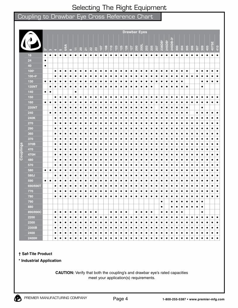
Selecting The Right EquipmentCoupling to Drawbar Eye Cross Reference Chart
2* 3 4 5 6/6A
8 11 20 21 22 23 107
108
110
123
125
126
127
200
200L
203
205
207
238D
B†
245D
B†
245D
B-3
†
300
304
305
306
307
309
405
407S
E
410
16 • • • • • • • • • • • • • • • • • • • • • • • • • • • • • • • • • • •24 •40 •100† • • • • • • • • • • • • • • • • • • • • • • • • • • • • • • • •100-4† • • • • • • • • • • • • • • • • • • • • • • • • • • • • • • • • •130 • • • • • • • • • • • • • • • • • • • • • • • • • • • • • • • •135NT • • • • • • • • • • • • • • • • • • • • • • • • • • • •140 • • •150 • • • • • • • • • • • • • • • • • • • • • • • • • • • • • • • • •160 • • • • • • • • • • • • • • • • • • • • • • • • • • • • • • • • • • •235NT • • • • • • • • • • • • • • • • • • • • • • • • • • •240 • • • • • • • • • • • • • • • • • • • • • • • • • • • • • • • • •240K • • • • • • • • • • • • • • • • • • • • • • • • • • • • • • • • •270 • • • • • • • • • • • • • • • • • • • • • • • • • • • • • • • • •290 • • • • • • • • • • • • • • • • • • • • • • • • • • • • • • • • •360 • • • • • • • • • • • • • • • • • • • • • • • • • • • • • • • • •370 • • • • • • • • • • • • • • • • • • • • • • • • • • • • • • • • •370B • • • • • • • • • • • • • • • • • • • • • • • • • • • • • • • • •470 • • • • • • • • • • • • • • • • • • • • • • • • • • • • • • • • •470H • • • • • • • • • • • • • • • • • • • • • • • • • • • • • • • • •480 • • • • • • • • • • • • • • • • • • • • • • • • • • • • • • • • •570 • • • • • • • • • • • • • • • • • • • • • • • • • • • • • • • • •580 • • • • • • • • • • • • • • • • • • • • • • • • • • • • • • • • • • •580J • • • • • • • • • • • • • • • • • • • • • • • • • • • • • • • • •590 • • • • • • • • • • • • • • • • • • • • • • • • • • • • • • • • • • •690/690T • • • • • • • • • • • • • • • • • • • • • • • • • • • • • • • • •770 • • • • • • • • • • • • • • • • • • • • • • • • • • • • • • • • •780 • • • • • • • • • • • • • • • • • • • • • • • • • • • • • • • • •790 • • • • • • • •880 • • • • • • • •890/890C • • • • • • • • • • • • • • • • • • • • • • •2200 • • • • • • • • • • • • • • • • • • • • • • • • • • • • • • • • •2300 • • • • • • • • • • • • • • • • • • • • • • • • • • • • • • • • •2300B • • • • • • • • • • • • • • • • • • • • • • • • • • • • • • • • •2400 • • • • • • • • • • • • • • • • • • • • • • • • • • • • • • • • •2400H • • • • • • • • • • • • • • • • • • • • • • • • • • • • • • • • •
Co
up
lin
gs
Drawbar Eyes
† Saf-Tite Product
* Industrial Application
CAUTION: Verify that both the coupling’s and drawbar eye’s rated capacitiesmeet your application(s) requirements.

1-800-255-5387 • www.premier-mfg.compremier manufacturing company Page 5
SAFETY WARNINGThis product is designed for towing under normal
conditions within the stated gross trailer weight capacity of the drawbar eye being used. Do not overload or
abuse this product. Overloading or abuse may lead to property damage, severe injury, or death.
Bushing I.D.:Bushing O.D.:
Bushing Length:Unit Weight:
2 in. (51 mm)3 1/2 in. (89 mm)3 1/2 in. (89 mm)26.3 lbs. (11.9 kg)
Model 340S / 340SA Front End Assembly
STANDARD INSTALLATION DRAWING
SPECIFICATIONS
PARTS & ACCESSORIES
Parts Included- 346 Housing- 349 Washer- 348 or *348A Bushings (*340SA comes with 348A Poly Bushings)
Bushing Replacements(Use ONLY Premier’s Bushings):
- 348 (Rubber) or 348A (Poly)
Drawbar Eye is NOT included(Use ONLY Premier’s Drawbar Eyes):
- 207S Drawbar Eye- 307S Drawbar Eye- 405S Drawbar Eye- 410S Drawbar Eye
Accepts 3 in. (76 mm) standard channel or square tubing.

1-800-255-5387 • www.premier-mfg.compremier manufacturing company Page 6
Model 340S / 340SA Front End AssemblyINSTALLATION
These instructions are ONLY for Premier 207S, 307S, 405S and 410S Drawbar Eyes, and Premier 348 and 348A Bushings, installed in a Premier 340S or 340SA Front End Assembly. Any substitution or use of non-Premier components in the 340S/340SA Front End Assembly VOIDS ALL PRODUCT WARRANTY.
Installation Procedure:
1. The 340S and 340SA Front End Assemblies and accompanying drawbar eye must be installed to comply with the Federal Motor Carrier Safety Regulations. Specifically, Section 393.70, Paragraph C: “Towing of Full Trailers.” Prior to install or operation, consult with local, State and Federal agencies, as there may be additional applicable laws governing installation and use of this product.
2. One of the three attached Welding Procedure Specifications; GMAW, SMAW or FCAW, must be followed. Welding should only be performed by a certified welder skilled in structural welding practices.
3. All weld locations must be clean, paint free and void of any moisture, oil, grease, oxides or loose or thick scale.
4. The front end structure that the 346 Housing attaches to must be of sufficient strength to withstand the load rating of the drawbar eye it is used with. The housing accommodates a front end structure consisting of two 3” square tubes, or channel, with possible converging angles that range from 8° to 46° as shown in Figure 1.
5. Fit-up, between both tubes and the mounting surfaces of the 346 Housing, must be flush, as failure to have a flush fit prior to welding will cause the capacities to be negatively affected. Figure 1A shows one possible example of an improper fit-up that must be avoided.
6. Attach the 346 Housing to the front end tubes with a minimum 3/8” fillet weld that encompasses the entire interface between the housing and each 3” tube, as shown in
Figure 1.
340S / 340SA Assembly after Welding (Premier 207S, 307S, 405S & 410S Drawbar Eyes only) (340S: Premier 348 Rubber Bushings only) (340SA: Premier 348A Poly Bushings only)
7. Allow the finished structure to cool.8. Slide the bushings into each end of the 346
Housing.9. Using extreme caution to avoid damaging or
nicking the threads, slide the drawbar eye all the way through each bushing.
10. Clean and lubricate all visible threads.11. Slide the 349 Washer onto the threaded end of
the drawbar eye.12. Lubricate the open face of the 349 Washer
with 30wt. oil where the 416 Locknut will rotate against it (see Figure 3).
13. Thread the 416 Locknut onto the drawbar eye just far enough to remove any free play from the 349 Washer.
14. If an initial gap exists between the flat flanged base of the drawbar eye and the face of the front bushing (see Figure 2), then slowly tighten the 416 Locknut until the gap just disappears as shown in Figure 3.
15. Note the location of one of the 416 Locknut faces relative to a spot on the 346 Housing (see Figure 3).
16. Tighten the 416 Locknut: - Using 348 Rubber Bushings: Turn the 416
Locknut between two and three complete revolutions from the position shown in
Figure 3. - Using 348A Poly Bushings: Turn the 416
Locknut no fewer than three complete revolutions from the position shown in
Figure 3.17. Place the 208 Snap Ring in the groove at
the end of the drawbar eye shaft to complete the assembly as shown in Figure 4. Use caution when installing the snap ring and make certain not to over expand it, as this will cause permanent damage to the snap ring.

1-800-255-5387 • www.premier-mfg.compremier manufacturing company Page 7
Model 340S / 340SA Front End Assembly
Figure 1
INSTALLATION
FIG. 1A
Figure 2
18. For the final installation instructions of the 340S/340SA Front End Assembly using a 405 or 410 Swivel Drawbar Eye, reference the drawbar eye’s specific Installation, Inspection, Operation and Maintenance Guide. These guides include instructions for attaching Premier’s 281 or 282 Air Chamber rod to the 405 or 410 Drawbar Eye Pushrod.
19. “IMPORTANT WARNINGS!” sticker was enclosed. This must be attached to the front end, adjacent to the drawbar eye, visible for the end user to read.
Please note: All applications vary and this is a recommended install starting point for bushing tightness at 70°F ambient air temperature. Varying conditions and applications may require a different initial set up.

1-800-255-5387 • www.premier-mfg.compremier manufacturing company Page 8
INSTALLATION
Figure 4
Figure 3
Model 340S / 340SA Front End Assembly

1-800-255-5387 • www.premier-mfg.compremier manufacturing company Page 9
1. Visually inspect the drawbar eye for cracks, impact damage and/or deformation before each and every use. Do NOT use if any of these conditions exist.
2. If the original cross-section of the eye loop has been reduced by 20% or greater, the drawbar eye is NOT to be used and is considered out-of-service.
3. Over time, slack may develop between the bushings and drawbar eye. Therefore, clean and inspect every 90 days or sooner if your application dictates, and adjust or replace the bushings if slack is noted.
4. This product is designed to be operated within its free rotation limits. It is the responsibility of the vehicle designer/end user to assure that these limits are not exceeded (not binding/jackknife).
5. WARNING: Prior to towing, make certain that adequately rated safety chains have been properly connected.
6. Never weld on any Premier drawbar eye in order to repair damaged or worn areas. Field and/or shop weld repairs are inadequate and may further weaken the drawbar eye.
INSPECTION / OPERATION / MAINTENANCEModel 340S / 340SA Front End Assembly
- Never attempt weld repair of damaged or worn drawbar eyes or front end assemblies- Clean and inspect drawbar eyes and eye assemblies for damage or excessive wear before each and every use- All welds should be performed by a certified welder skilled in structural welding practices
- Drawbar structure as well as welds attaching front end assembly to drawbar must be of sufficient strength to withstand the load rating of the drawbar eye- Do not bind-up (Jackknife) any application as stresses can cause damage to products or components, resulting in failure and detachment of the trailer while in use- Do not apply lubricants to the coupling hook or drawbar eye loop, as they can cover up possible damage and accelerate wear
IMPORTANT GUIDELINES that apply to all Premier Front End Assemblies

1-800-255-5387 • www.premier-mfg.compremier manufacturing company Page 10
Model 340S / 340SA Front End AssemblyWELDING PROCEDURES
GMAW
SMAW FCAW
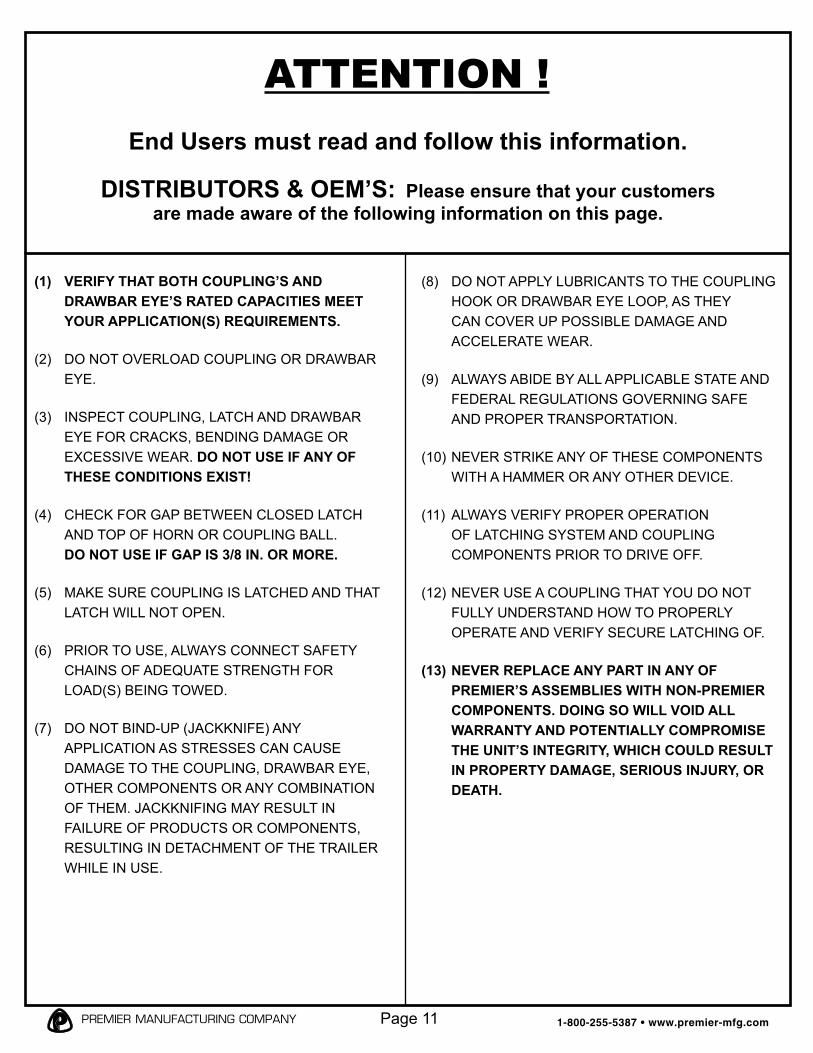
(1) VERIFY THAT BOTH COUPLING’S AND DRAWBAR EYE’S RATED CAPACITIES MEET YOUR APPLICATION(S) REQUIREMENTS.
(2) DO NOT OVERLOAD COUPLING OR DRAWBAR EYE.
(3) INSPECT COUPLING, LATCH AND DRAWBAR EYE FOR CRACKS, BENDING DAMAGE OR EXCESSIVE WEAR. DO NOT USE IF ANY OF THESE CONDITIONS EXIST!
(4) CHECK FOR GAP BETWEEN CLOSED LATCH AND TOP OF HORN OR COUPLING BALL. DO NOT USE IF GAP IS 3/8 IN. OR MORE.
(5) MAKE SURE COUPLING IS LATCHED AND THAT LATCH WILL NOT OPEN.
(6) PRIOR TO USE, ALWAYS CONNECT SAFETY CHAINS OF ADEQUATE STRENGTH FOR LOAD(S) BEING TOWED.
(7) DO NOT BIND-UP (JACKKNIFE) ANY APPLICATION AS STRESSES CAN CAUSE DAMAGE TO THE COUPLING, DRAWBAR EYE, OTHER COMPONENTS OR ANY COMBINATION OF THEM. JACKKNIFING MAY RESULT IN FAILURE OF PRODUCTS OR COMPONENTS, RESULTING IN DETACHMENT OF THE TRAILER WHILE IN USE.
(8) DO NOT APPLY LUBRICANTS TO THE COUPLING HOOK OR DRAWBAR EYE LOOP, AS THEY CAN COVER UP POSSIBLE DAMAGE AND ACCELERATE WEAR.
(9) ALWAYS ABIDE BY ALL APPLICABLE STATE AND FEDERAL REGULATIONS GOVERNING SAFE AND PROPER TRANSPORTATION.
(10) NEVER STRIKE ANY OF THESE COMPONENTS WITH A HAMMER OR ANY OTHER DEVICE.
(11) ALWAYS VERIFY PROPER OPERATION OF LATCHING SYSTEM AND COUPLING COMPONENTS PRIOR TO DRIVE OFF.
(12) NEVER USE A COUPLING THAT YOU DO NOT FULLY UNDERSTAND HOW TO PROPERLY OPERATE AND VERIFY SECURE LATCHING OF.
(13) NEVER REPLACE ANY PART IN ANY OF PREMIER’S ASSEMBLIES WITH NON-PREMIER COMPONENTS. DOING SO WILL VOID ALL WARRANTY AND POTENTIALLY COMPROMISE THE UNIT’S INTEGRITY, WHICH COULD RESULT IN PROPERTY DAMAGE, SERIOUS INJURY, OR DEATH.
ATTENTION !End Users must read and follow this information.
DISTRIBUTORS & OEM’S: Please ensure that your customers are made aware of the following information on this page.
1-800-255-5387 • www.premier-mfg.compremier manufacturing company Page 11

WARRANTY: We warrant all Premier products to be free from defects in material or workmanship for one year. We will repair or replace, at our option, any Premier product which our examination reveals to be defective, provided that the product is returned to our factory, at Tualatin, Oregon transportation prepaid, within one year of purchaseby the first retail purchaser. Our warranty does not extend to products which have been subject to misuse, neglect, improper installation, maintenance or application, nor does our warranty extend to products which have been repaired or altered outside of Premier’s facility unless the repair or alteration has been expressly authorized inwriting by Premier. This warranty is in lieu of all other warranties, express or implied, and excludes warranties of merchantability, fitness for a particular purpose and otherwise, and in no event will Premier be liable for incidental, special, contingent or consequential damages.
DISCLAIMER: Although great care has been taken to ensure accurate information throughout this document,Premier Manufacturing Company must reserve the right to alter any information contained within. These changes include but are not limited to: Dimensional changes, load capacity and availability of any part or assembly.
© 2009 Premier Manufacturing Company
All rights reserved. Any reproduction of the photographic images or any other portion of this document, including but not limited to the photocopying, or retention and/or storagein a retrieval system of any kind, is strictly prohibited without prior express written permission from Premier Manufacturing Company.
WA
RN
ING
!T
his
enve
lope
con
tain
s im
port
ant
inst
ruct
ions
AN
D M
US
T R
EM
AIN
A
TT
AC
HE
D T
O T
HIS
FR
ON
T E
ND
A
SS
EM
BLY
. It
may
be
rem
oved
onl
y by
the
End
Use
r or
by
an O
rigin
al
Equ
ipm
ent
Man
ufac
ture
r w
ho
pres
erve
s th
is e
nvel
ope
and
inst
ruc-
tions
and
pro
vide
s it
to t
he e
nd u
ser.
pr
emie
r m
an
ufa
ctu
rin
g c
om
pan
yT
HE
FIR
ST
NA
ME
IN q
UA
LIT
Y C
OU
PL
ING
S80
0-25
5-53
87 (
503)
234
-920
2w
ww
.pre
mie
r-m
fg.c
om
1-800-255-5387 • www.premier-mfg.compremier manufacturing company Page 12
Revised: 04/09
Model 340S/340SA Front End AssemblyInstallation, etc.