function body material ip protection class ip65 (with...
TRANSCRIPT

Solenoids
24
IP Protection class
Dire
ct s
olen
oid
actu
ated
Body materialFunction
Oper
atio
n
2/2
3/2
Stai
nles
s st
eel
Bras
s
Grey
cas
t iro
n
Plas
tic r
esin
PVDF
Series
IP65 (with connector)
Buschjost820800 ... 7 barGÊ, GÁNC√13,83 l/min 30
¬ ¬8050, 8051
Herion 910000 ... 300 barGÂ ... GËNC / NO√1440 l/min 32
¬ ¬ ¬0700
Herion 950000 ... 40 barGÊ, GË, Ê NPTNC / NO√1700 l/min 34
¬ ¬0200, 0246,3206, 3204
0800, 0827,3803, 3805
0700, 3703
0800 93001001
Herion 951000 ... 50 barGÂ, GÊ, Ê NPTNC√520 l/min 36
¬ ¬0200, 0246,3206, 3204
Herion21023 / 210250 ... 10 barGÊ, GËNC√750 l/min 44
¬ ¬¬0800, 3803
Herion 210000 ... 50 barGÊ ... GËNC√1000 l/min 46
¬ ¬
1300, 1301
Herion 232000 ... 25 barGË ... G2NC/NO√16500 l/min 48
¬ ¬ ¬ ¬
1300, 1301
1500, 1501
1500, 1501 1600, 1601 1700, 1701
0800, 0827,3803, 3805
0700, 3703
WebberCartridge valve0 ... 10 barNC√125 l/min 52
¬ ¬¬
WebberExcel 22Dual control10 barNC√29 l/min 53
¬¬
WebberInk jet valve-0,5 ... 4,5 barNC, Changeover√100 c.c./min 54
¬¬ ¬
WebberBase portedmini valves0 ... 5 barNC/NOGÊ√90 l/min 56
¬¬
2/2 & 3/2 Solenoid operated valves
Page
no.

25
Explosion proof class
Zones 21, 22
II 2 G
EEx me
Zones 2, 22
II 3 GD
Zones 1, 2, 21, 22
II 2 G / II 2 D
EEx nAIP65
EEx dIP 66
EEx meIP 66
EEx mdEEx meIP 66
EEx meIP65
EEx mIP 66
4210/1, 4220/1, 4230/1,4270/1, 4280/1
4610/1/2/3, 4620/1/2/3, 4630/1/2/3,4670/1/2/3, 4680/1/2/3
8042
3216, 3217,3218, 3219
3817, 3818,3819
1440, 1441
1440, 1441
1570, 1571
1570, 1571
0290, 0291,0292, 0293
0290, 0291,0292, 0293
4210/1, 4220/1, 4230/1,4270/1, 4280/1
1480, 14811680, 1681
4610/1/2/3, 4620/1/2/3, 4630/1/2/3,4670/1/2/3, 4680/1/2/3
3216, 3217,3218, 3219
3817, 3818,3819
4270, 4271 4670, 4671, 4672, 4673

Solenoids
26
IP Protection class
IP65 (with connector)
Indi
rect
sol
enoi
d ac
tuat
ed
Body materialFunction
Oper
atio
n
2/2
3/2
Stai
nles
s st
eel
Bras
s
Zinc
allo
y
Plas
tic r
esin
Series
¬
Herion 910000 ... 300 barGÂ ... GËNC / NO√1440 l/min 32
¬ ¬ ¬
Buschjost82400 / 824100 ... 16 barGÊ ... G2, Ê ... 2 NPTNC√683 l/min 68
¬ ¬
9101
Buschjost85300 / 853100,5 ... 40 barGÊ ... G2, Ê ... 2 NPTNC√716 l/min 70
¬ ¬9151
Buschjost83620 / 836300,1 ... 10 barGÊ ... GÁNC√25,0 l/min 72
¬ ¬
8001
Buschjost824700,1 ... 10 barGÊ ... G1NC√141 l/min 74
¬ ¬
9101
0700 0800
9151
9300 1001
Webber Excel 22Â" BSP0 ... 12 barNC/NOGÂ√152 l/min 62
¬¬¬
¬
¬
¬
Webber Excel 22Hosetail0 ... 10 barNC√113 l/min 64
¬¬
Webber Excel 32Sub-basemounted0 ... 16 barNC/NO√150 l/min 66
¬¬
Webber Excel 32In-line0 ... 16 barNC/NOGÂ, GÊ√260 l/min 67
¬¬¬
WebberExcel 220 ... 10 barNCGÂ√77 l/min 60
¬¬
Webber watermanagementvalves0 ... 10 barNC√4,5 l/min 58
¬¬
Dire
ct s
olen
oid
actu
ated
2/2 & 3/2 Solenoid operated valves
Page
no.

27
Explosion proof class
Zones 1, 21
II 2 GD
EEx mIP67
9136

Solenoids
28
IP Protection class
IP65 (with connector)
Sole
noid
act
uate
d w
ith fo
rced
lifti
ng
Body materialFunction
Oper
atio
n
2/2
Stai
nles
s st
eel
Bras
s
Series
Buschjost82540 / 826400 ... 10 barGÊ ... G2Ê ... 2 NPTNC√683 l/min 80
¬ ¬9151, 9154
Buschjost82530 / 826300 ... 10 barGÊ ... GËÊ ... Ë NPTNC√28,3 l/min 82
¬ ¬8001
Buschjost85040 / 850500 ... 25 barGÁ ... G1Á ... 1 NPTNC√217 l/min 84
¬ ¬8301, 8304
Buschjost85140 / 841400 ... 16 barFlange PN 16NC√2400 l/min 86
¬ ¬8301, 8304
Buschjost82560 / 825700 ... 10 barGÊ ... GËÊ ... Ë NPTNC√28,3 l/min 88
¬ ¬9748, 9749
Buschjost82360 / 824600 ... 10 barGÊ ... G1Ê ... 1 NPTNC√133 l/min 90
¬ ¬8302, 8306
Buschjost85700 / 857100 ... 25 barGÊ ... G2Ê ... 2 NPTNC√717 l/min 92
¬ ¬9401, 9404
Buschjost85720 / 857300 ... 16 barGÊ ... G2Ê ... 2 NPTNC√683 l/min 94
¬ ¬9402, 9406
8401, 8404
8401, 8404
8401, 8404
8402, 8406
9501, 9504
9401, 9404 8401, 8404
Buschjost853201 ... 25 barGÊ ... G1Ê ... 1 NPTNC√175 l/min 76
¬ ¬9152
Buschjost82730 / 827400,1 ... 16 barGÊ ... G1Ê ... 1 NPTNC√158 l/min 78
¬ ¬9101, 9104
Indi
rect
sol
enoi
d ac
tuat
ed2/2 & 3/2 Solenoid operated valves
Page
no.
29
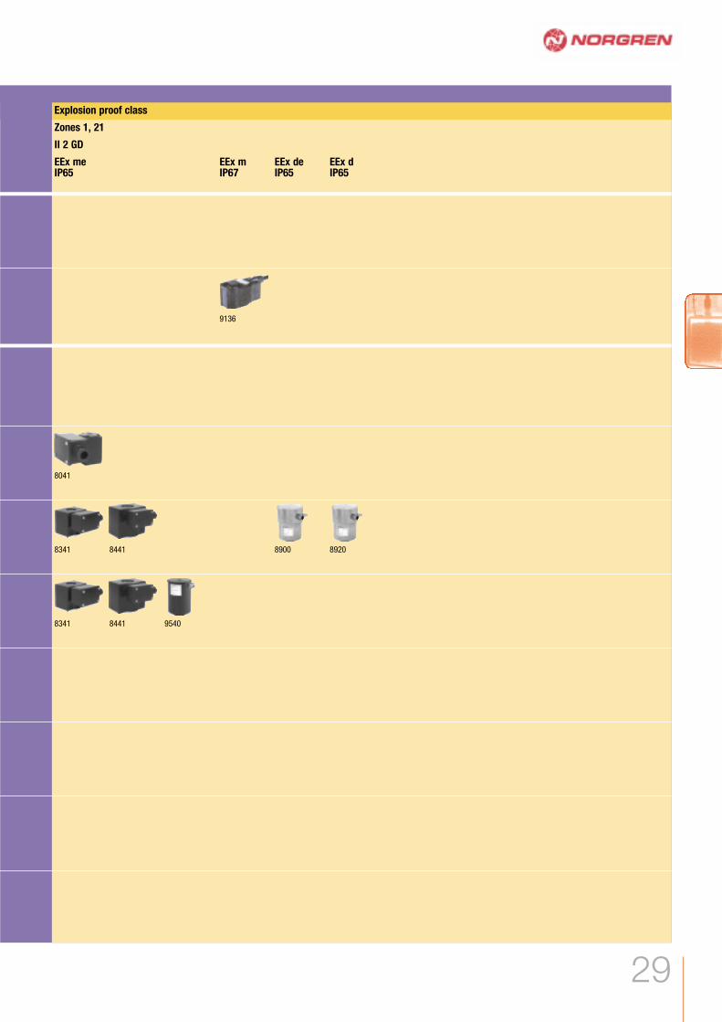
Explosion proof class
Zones 1, 21
II 2 GD
EEx meIP65
EEx deIP65
EEx mIP67
EEx dIP65
8041
8341
8341
8441
8441 9540
8900 8920
9136

30 www.norgren.com/fc/en30
Buschjost 82080 SeriesDirect solenoid actuated angle seat valves3 to 8 mm orifice (ND)2/2, NC, GÊ and GÁ
HHiigghh fflluuiidd ccoommppaattiibbiilliittyy tthhaannkkss ttooooppttiimmuumm mmaatteerriiaallss mmaattcchhiinnggSSuuiittaabbllee ffoorr vvaaccuuuummFFoorr hheeaavvyy--dduuttyy iinndduussttrriiaallaapppplliiccaattiioonnssHHeerrmmeettiicc sseeaall bbeettwweeeenn fflluuiidd aannddaaccttuuaattoorr CCoommppaacctt ddeessiiggnnFFoorr hhiigghhllyy ccoonnttaammiinnaatteedd fflluuiiddss
Technical dataMedium:Aggressive gases and liquidsViscosity:80 mm2/s (cSt) max.Flow direction:FixedMounting:Optional, but preferably withsolenoid verticalFluid temperature:-10°C to +110°C max.Ambient temperature:-10°C to +50°C max.Consult our Technical Service for use below +2°C
MaterialsBody: PVDF Seat seal: EPDM Internal parts: PTFE bellows
For contaminated fluids installationof an upstream filter isrecommended.
Options selector 8208X ˙˙ ˙˙˙˙ ˙˙˙˙˙
SSoolleennooiidd SSuubbssttiittuutteed.c. 8050a.c. 8051EEx me II T3 8042
VVoollttaaggee SSuubbssttiittuuttee24 V d.c. 0240024 V a.c., 40 to 60 Hz 02449110 V a.c., 40 to 60 Hz 11049230 V a.c., 40 to 60 Hz 23049
AAlltteerrnnaattiivvee vveerrssiioonn SSuubbssttiittuutteeSeat seal material FPM,preferably for fuels and oils,max. fluid temperature +110°C 03Seat and soft seal material PTFE,max. fluid temperature +110°C 06
3,0 G 1/4 0 ... 7 0,23 0,3 8208000xxxx*****4,5 G 1/4 0 ... 5 0,42 0,3 8208060xxxx*****6,0 G 1/4 0 ... 2 0,62 0,3 8208070xxxx*****8,0 G 1/4 0 ... 1 0,83 0,3 8208080xxxx*****3,0 G 3/8 0 ... 7 0,23 0,3 8208100xxxx*****4,5 G 3/8 0 ... 5 0,42 0,3 8208160xxxx*****6,0 G 3/8 0 ... 2 0,62 0,3 8208170xxxx*****8,0 G 3/8 0 ... 1 0,83 0,3 8208180xxxx*****
MMooddeellOOrriiffiiccee ((mmmm)) PPoorrtt ssiizzee OOppeerraattiinnggpprreessssuurree ((bbaarr))
kkvv vvaalluueemm33//hh**
TToottaall wweeiigghhtt((kkgg))
* Cv (US) Ÿ kv x 1,2xxxx Insert solenoid codes from table below. ***** Insert voltage codes from table below
Other voltages on request
2/2 & 3/2 Solenoid operated valves

31
Buschjost 82080 SeriesDirect solenoid actuated angle seat valves
3 to 8 mm orifice (ND)2/2, NC, GÊ and GÁ
Electrical details for solenoid operators
Version as per VDE 0580, duty cycle 100%.Power consumption with coil temperature of +20°C. With the solenoid coil at operating temperature (d.c.), the power consumption is up to 30% lower for physical reasonsCable clamping range 5 to 10 mm
MMooddeellPPoowweerr ccoonnssuummppttiioonn VVoollttaaggee2244 VV dd..cc..((WW))
223300 VV aa..cc..((VVAA))
CCaatteeggoorryy2244 VV dd..cc..((mmAA))
223300 VV aa..cc..((mmAA))
PPrrootteeccttiioonn ccllaassss TTeemmppeerraattuurreess °°CCFFlluuiidd** AAmmbbiieenntt****
EElleeccttrriiccaall ccoonnnneeccttiioonn kkgg SSoolleennooiiddddrraawwiinngg nnoo..##
CCiirrccuuiittddiiaaggrraamm##dd..cc.. aa..cc..
12 20/16 500 70 – IP 65 +100 max. -25 ... +50 DIN EN 175301-803 0,22 16 1 1 805012 13 VA/12 W 500 59 – IP 65 +110 max. -25 ... +50 DIN EN 175301-803 0,22 16 – 2 8051
12 13 VA/12 W 500 59 II 2 G D EEx me II T3, IP 65 +80 max. -20 ... +40 Connector body 0,30 23 2 6 8042
BB HH HH11 LL82080XX 8050 G 1/4 70 90 77 4482080XX 8051 G 1/4 70 90 77 4482081XX 8050 G 3/8 70 90 77 4482081XX 8051 G 3/8 70 90 77 44
MMooddeell CCoonnnneeccttiioonn
# For solenoid dimensional drawingsand circuit diagrams, see page 97
Solenoid and device socket can be turned through 4 x 90°
* The maximum temperature depends on the valve type** The maximum temperature may be higher, depending on the application.

32 www.norgren.com/fc/en32
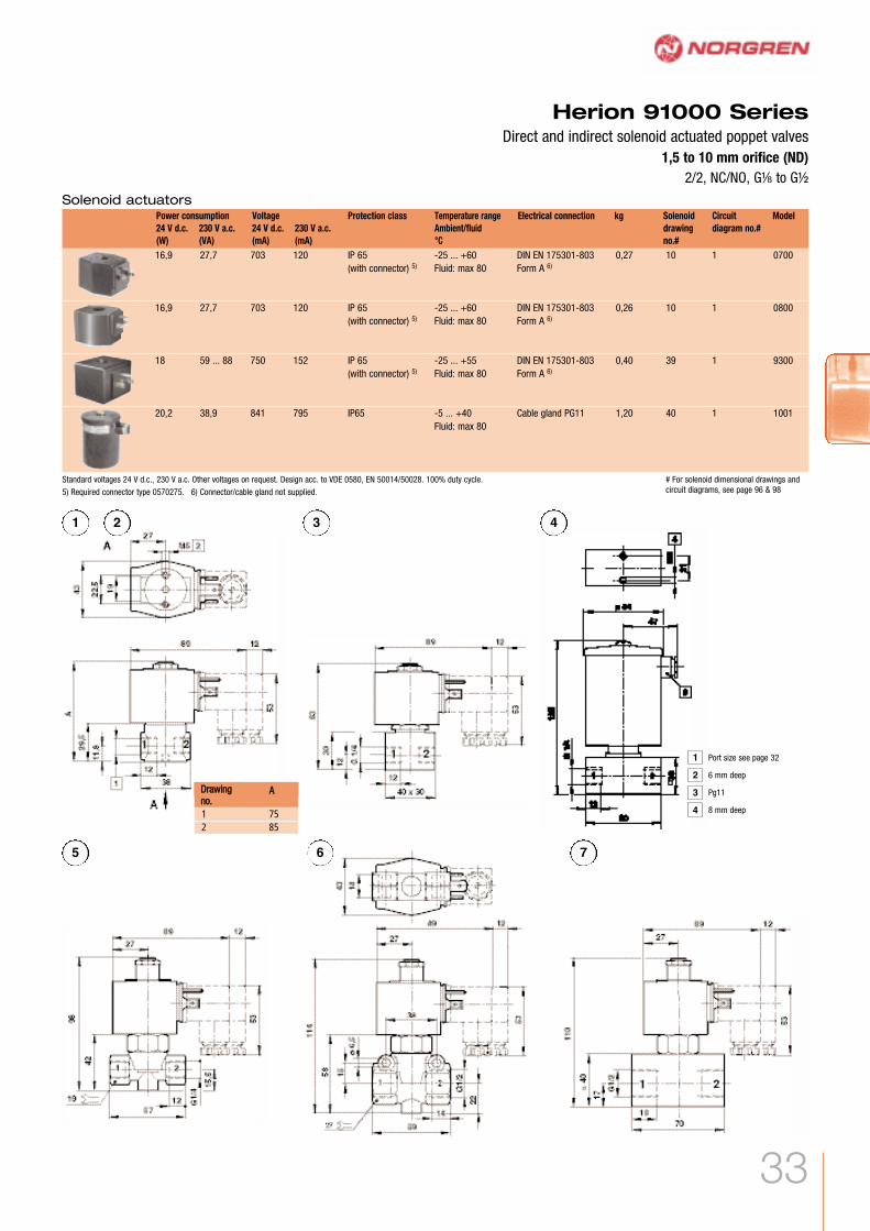
Herion 91000 SeriesDirect and indirect solenoid actuated poppet valves1,5 to 10 mm orifice (ND)2/2, NC/NO, GÂ to GË
HHiigghh sswwiittcchhaabbllee ∂∂ ppHHeerrmmeettiiccaallllyy sseeaalleedd ppooppppeett vvaallvveessEExxcceelllleenntt rreeppeeaattaabbiilliittyy ooff sswwiittcchhiinngg ttiimmeess
Technical dataMedium:For neutral gaseous and liquidfluids Operating pressure:0 to 300 bar / 1 to 250 barFlow direction:FixedMounting position:Optional, preferably with solenoidon topFluid temperature:-10 to +60 ˚C AU (polyurethane)-40 to +80 ˚C POM (Delrin)-40 to +120 ˚C PVDF / PIWith minus temperatures, use conditioned dry air.If installed in the open protect all connectionsagainst the penetration of moisture
Ambient temperature:Depending on solenoid system-10, -25, -40 to +55, +70,+100 ˚CConsult our Technical Service for use below +2°C
MaterialsHousing: brass, stainless steel1.4305Seat seal: see fluid temperatureInner parts: brass, stainless steel1.4305
For contaminated fluidsinstallation of an upstream filteris recommended.
1,5 G 1/4 NC 0 80 80 0,068 Brass AU 0,55 1 9106200.0700*****1 G 1/4 NC 0 200 200 0,035 S/steel POM 0,6 3 9106250.0800*****1,2 G 1/4 NC 0 300 300 0,035 S/steel PI 1,2 4 9922202.1001*****1,8 G 1/4 NC 0 175 175 0,07 S/steel PI 1,2 4 9922203.1001*****1 G 1/4 NC 0 80 – 0,035 Brass AU 0,55 2 9106212.0700*****6 G 1/4 NC 1 – 80 0,57 Brass POM 0,6 5 9107200.0700*****6 G 1/4 NC 1 80 – 0,57 Brass POM 0,6 5 9107400.0700***** 10 G 1/2 NC 1 – 80 1,44 Brass POM 0,76 6 9107300.0700*****10 G 1/2 NC 1 80 – 1,44 Brass POM 0,76 6 9107500.0700*****10 G 1/2 NC 1 – 130 1,40 S/steel PVDF 0,76 7 9107318.0800***** 10 G 1/2 NC 1 130 – 1,40 S/steel PVDF 0,76 7 9107525.0800*****10 G 1/2 NC 1 – 170 1,40 S/steel PVDF 0,76 7 9107318.9300*****10 G 1/2 NC 1 170 – 1,40 S/steel PVDF 0,76 7 9107525.9300*****6 G 1/4 NO 10 – 80 0,57 Brass POM 0,6 5 9107212.0700*****6 G 1/4 NO 10 80 – 0,57 Brass POM 0,6 5 9107412.0700***** 10 G 1/2 NO 10 – 80 1,44 Brass POM 0,76 6 9107312.0700*****10 G 1/2 NO 10 80 – 1,44 Brass POM 0,76 6 9107512.0700*****
2)
1)
1)
1)
2)
* Cv (US) = kv x 1,2
Portsize
FunctionOrifice(mm)
kv valuem3/h*
kg Drawingno.
Model
***** Insert voltage codes from table below
1) Suitable for d.c. only; for a.c. use connector with rectifier, model no. 0663303.2) Not suitable for water.
Operating pressure (bar)Min. Fluid max.
Gaseous Liquid
MaterialsSeat sealHousing
Options selector
992220X ˙˙˙˙ ˙˙˙˙˙910XXXX ˙˙˙˙ ˙˙˙˙˙
SSoolleennooiiddSee solenoid tables
VVoollttaaggee SSuubbssttiittuuttee24 V d.c. 0240024 V a.c. 02450110 V a.c. 11050230 V a.c. 23050
Accessories
0570275
Connectors
Other voltages on request
2/2 & 3/2 Solenoid operated valves
33
Herion 91000 SeriesDirect and indirect solenoid actuated poppet valves
1,5 to 10 mm orifice (ND)2/2, NC/NO, GÂ to GË
AA
1 752 85
DDrraawwiinnggnnoo..
1 2 3 4
5 6 7
16,9 27,7 703 120 IP 65 -25 ... +60 DIN EN 175301-803 0,27 10 1 0700(with connector) 5) Fluid: max 80 Form A 6)
16,9 27,7 703 120 IP 65 -25 ... +60 DIN EN 175301-803 0,26 10 1 0800(with connector) 5) Fluid: max 80 Form A 6)
18 59 ... 88 750 152 IP 65 -25 ... +55 DIN EN 175301-803 0,40 39 1 9300(with connector) 5) Fluid: max 80 Form A 6)
20,2 38,9 841 795 IP65 -5 ... +40 Cable gland PG11 1,20 40 1 1001Fluid: max 80
ModelVoltage Protection class Temperature rangeAmbient/fluid°C
Electrical connection kg Solenoiddrawingno.#
Circuitdiagram no.#
Power consumption230 V a.c.(VA)
24 V d.c.(W)
230 V a.c.(mA)
24 V d.c.(mA)
Standard voltages 24 V d.c., 230 V a.c. Other voltages on request. Design acc. to VDE 0580, EN 50014/50028. 100% duty cycle.
Solenoid actuators
4
3
2
1 Port size see page 32
6 mm deep
Pg11
8 mm deep
# For solenoid dimensional drawings andcircuit diagrams, see page 96 & 985) Required connector type 0570275. 6) Connector/cable gland not supplied.

34 www.norgren.com/fc/en34
Herion 95000 Series Direct solenoid actuated poppet valves1,5 to 6 mm orifice (ND)2/2, NC/NO, GÊ, GË, Ê NPT
WWoorrkkiinngg ffrroomm 00 bbaarr uuppSShhoorrtt sswwiittcchhiinngg ttiimmeessSSuuiitteedd ffoorr ffiinnee vvaaccuuuumm 11..3333··1100--33 mmbbaarrAAsssseemmbblleedd ooiill aanndd ggrreeaassee--ffrreeeeFFoorr aa..cc.. ssoolleennooiidd ssyysstteemmss wwiitthh iinntteeggrraatteeddrreeccttiiffiieerr ((4400 ttoo 6600 HHzz))TThheessee ssoolleennooiiddss aarree AATTEEXX aanndd FFMM,, CCSSAA,,XXPP aapppprroovveedd
Technical dataMedium:Neutral gaseous and liquid fluids Operating pressure:0 to 40 bar Flow direction:Fixed Mounting position:Optional, preferably with solenoid on top Fluid temperature:-25 to +80°C NBR (Perbunan)-10 to +120°C FPM (Viton)*-40 to +140°C EPDM-50 to +180°C PTFE (Teflon)-10 to +180°C FFPM (Kalrez)* For water +90°C
Ambient temperature:Depending on solenoid system-25 to +80°C Consult our Technical Service for use below +2°C
MaterialsHousing: BrassSeal: NBR (Perbunan)Inner parts: brass, steel 1.4104/430F
Alternative modelsSolenoid with low power consumptionSolenoid for higher temperaturesSolenoid in protection class EEx mSolenoid for outdoor applicationSolenoid with FM-/CSA-certification(NEMA 4, 4X, 7 and 9)Operating pressure to 50 bar
For contaminated fluids installation of anupstream filter is recommended.
13B G1/4 NC 1,5 0 ... 40 bar 0,07 0,21 1 9500100xxxx*****13B G1/4 NC 2 0 ... 35 bar 0,12 0,21 1 9500200xxxx*****13C G1/4 NC 3 0 ... 10 bar 0,20 0,21 1 9500300xxxx*****13D G1/4 NC 4 0 ... 12 bar 0,35 0,21 1 9500400xxxx*****16D G1/4 NC 6 0 ... 5 bar 0,55 0,25 2 9501600xxxx*****16D G1/2 NC 12 0 ... 1 bar 1,70 0,80 4 9501700xxxx*****13B G1/4 NO 2 0 ... 20 0,10 0,21 3 9502210xxxx*****13B G1/4 NO 3 0 ... 10 0,16 0,21 3 9502310xxxx*****13B 1/4 NPT NC 3 0 ... 35 bar 0,12 0,21 1 9503200xxxx*****13C 1/4 NPT NC 3 0 ... 10 bar 0,20 0,21 1 9503300xxxx*****13D 1/4 NPT NC 4 0 ... 12 bar 0,35 0,21 1 9503400xxxx*****16D 1/4 NPT NC 6 0 ... 5 bar 0,55 0,25 2 9504600xxxx*****
xxxx Insert solenoid code from tables below. ***** Insert voltage code from table below
Portsize
Orifice(mm)
Operatingpressure (bar)
kv valuem3/h*
kg Drawingno.
ModelSolenoidgroup**
Function
Options selector 950XXX˙ ˙˙˙˙ ˙˙˙˙˙
SSoolleennooiiddSee solenoid tables, pages 37 to 41
VVoollttaaggee SSuubbssttiittuuttee24 V d.c. 0240024 V a.c. 02450110 V a.c. 11050230 V a.c. 23050
MMaatteerriiaall –– sseeaatt sseeaall SSuubbssttiittuutteeNBR (Perbunan) 0EPDM 1FKM (Viton) 2PTFE (Teflon) (ND 1,5 to 4, NC) 3FFKM (Kalrez) 4Rubin (ND 2 & 3, NC) 5
* Cv (US) = kv x 1,2** For solenoid details, see pages 37 ... 41
Other voltages on request
2/2 & 3/2 Solenoid operated valves
AccessoriesCable glands
EEx e 0588819 (for solenoid 42xx /46xx M20 x 1,5) 0570275EEx d 0588851 (for solenoid 46xx M20 x 1,5)EEx d, EEx e 0588925 (for solenoid 46xx 1/2-14 NPT)
ConnectorsProtection class EEx e, EEx d (ATEX), Ms nickel plated brass

35
Herion 95000 Series Direct solenoid actuated poppet valves
1,5 to 6 mm orifice (ND)2/2, NC/NO, GÊ, GË, Ê NPT
1 2
3 4

36 www.norgren.com/fc/en36
Herion 95100 SeriesDirect solenoid actuated poppet valves, stainless steel 2 to 6 mm orifice (ND)2/2, NC, GÂ, GÊ, Ê NPT
WWoorrkkiinngg ffrroomm 00 bbaarr uuppSSuuiitteedd ffoorr ffiinnee vvaaccuuuumm ddoowwnn 11..3333··1100--33mmbbaarr··II//ss AAsssseemmbblleedd ffrreeee ooff ooiill aanndd ggrreeaasseeTThheessee ssoolleennooiiddss aarree AATTEEXX aanndd FFMM,, CCSSAA,,XXPP aapppprroovveedd
Technical dataMedium:For aggressive gaseous and liquidfluids*Operating pressure:0 to 50 barFlow direction:FixedMounting position:Optional, preferably with solenoid ontopFluid temperature:-10 to +120°C FKM (Viton)Ambient temperature:Depending on solenoid system-10, -25, -40 to +55, +70, +100°CWith minus temperatures, use conditioned dry air. Ifinstalled in the open protect all connections against thepenetration of moistureConsult our Technical Service for use below +2°C
MaterialsHousing: stainless steel 1.4571/316TSeat seal: FKM (Viton)Inner parts: stainless steel
AlternativemodelsValves with ultra-low leakageFluid temperatures:-40 to +140°C EPDM-50 to +180°C PTFE (Teflon)-10 to +180°C FFKM (Kalrez)With minus temperatures, use conditioned dry air. Ifinstalled in the open protect all connections against thepenetration of moisture
For contaminated fluids installation ofan upstream filter is recommended.
13D 2 G1/8 0 ... 50 0,1 0,15 1 9510202xxxx*****13B 2 G1/8 0 ... 20 0,1 0,15 1 9510202xxxx*****16D 4 G1/4 0 ... 12 0,34 0,21 2 9511402xxxx*****16C 4 G1/4 0 ... 5 0,34 0,21 2 9511402xxxx*****16D 6 G1/4 0 ... 5 0,52 0,21 2 9511602xxxx*****16C 6 G1/4 0 ... 3 0,52 0,21 2 9511602xxxx*****16D 4 1/4 NPT 0 ... 12 0,34 0,21 2 9514402xxxx*****16C 4 1/4 NPT 0 ... 5 0,34 0,21 2 9514402xxxx*****16D 6 1/4 NPT 0 ... 5 0,52 0,21 2 9514602xxxx*****16C 6 1/4 NPT 0 ... 3 0,52 0,21 2 9514602xxxx*****
OOrriiffiiccee ((mmmm)) PPoorrtt ssiizzee OOppeerraattiinnggpprreessssuurree ((bbaarr))
kkvv vvaalluueemm33//hh**
MMooddeellSSoolleennooiiddggrroouupp
Options selector 951XX0˙ ˙˙˙˙ ˙˙˙˙˙
SSoolleennooiiddSee solenoid tables
VVoollttaaggee SSuubbssttiittuuttee24 V d.c. 0240024 V a.c. 02450110 V a.c. 11050230 V a.c. 23050
MMaatteerriiaall –– sseeaatt sseeaall SSuubbssttiittuutteeEPDM 1FKM (Viton) 2PTFE (Teflon), O-ring static FKM (Viton) 3FFKM (Kalrez) 4
* Cv (US) Ÿ kv x 1,2
Other voltages on request
xxxx Insert solenoid code from tables below. ***** Insert voltage code from table below
kkgg DDrraawwiinnggnnoo..
2/2 & 3/2 Solenoid operated valves
AccessoriesCable glands
EEx e 0588819 (for solenoid 42xx /46xx M20 x 1,5) 0570275EEx d 0588851 (for solenoid 46xx M20 x 1,5)EEx d, EEx e 0588925 (for solenoid 46xx 1/2-14 NPT)
ConnectorsProtection class EEx e, EEx d (ATEX), Ms nickel plated brass

37
8,0 – 331 – – IP 65 -25 ... +60 DIN EN 175301-803 0,15 8 1 0246 7)
(with connector) 5) Fluid: max. 80 Form A 6)
– 9,2 – 40 – IP 65 -25 ... +60 DIN EN 175301-803 0,16 9 7 3206 7)
(with connector) 5) Fluid: max. 80 Form A 6)
8,0 – 331 – II3G EEx nA II T4 -20 ... +60 DIN EN 175301-803 0,16 8 1 3216II3D IP 65 T 110°C Form A with special screw
– 9,2 – 40 II3G EEx nA II T4 -20 ... +60 DIN EN 175301-803 0,16 9 6 3218II3D IP 65 T 110°C Form A with special screw
6,9 – 289 – II2G EEx m II T4 -20 ... +60 3 m cable 0,40 12 4 0292II2D IP 66
T 110°C 1)
– 8,7 – 34 II2G EEx m II T4 -20 ... +60 3 m cable 0,40 12 7 0293II2D IP 66
T 110°C 2)
3,9 – 162 – II2G EEx me II T4 T6: -40 ...+55 M20 x 1,5 6) 0,50 13 4 4210 8)
II2D IP 66 T4: -40 ... +80T 110°C 2)
– 5,3 – 23 II2G EEx me II T6/T4 T6: -40 ...+55 M20 x 1,5 6) 0,50 13 7 4211 8)
II2D IP 66 T4: -40 ... +80T 130°C 2)
3,9 – 162 – II2G EEx md IIC T6: -40 ...+55 1/2-14 NPT 6) 0,80 14 4 4610 8)
II2D T6/T4 T4: -40 ... +80EEx me IIT6/T4IP 66T 130°C 3)
– 5,3 – 23 II2G EEx md IIC T6: 1/2-14 NPT 6) 0,80 14 7 4611 8)
II2D T6/T4 -40 ...+55EEx me II T4:T6/T4 -40 ... +80IP 66T 130°C 3)
3,9 – 162 – II2G EEx md IIC T6: M20 x 1,5 6) 0,80 14 7 4612 8)
II2D T6/T4 -40 ...+55EEx me II T4:T6/T4 -40 ... +80IP 66T 130°C 3)
– 5,3 – 23 II2G EEx md IIC T6: M20 x 1,5 6) 0,80 14 7 4613 8)
II2D T6/T4 -40 ...+55EEx me II T4:T6/T4 -40 ... +80IP 66T 130°C 3)
5,3 – 23 – – Div. 1 and 2 -20 ... +60 Flying leads 450 mm 0,50 15 1 3722CI.I, Gr.A-DCI.II, Gr.E-GCI.III,T3C (160°C)NEMA 4,4X,6,6P, 7,9 4)
– 5,3 – 23 – Div. 1 and 2 -20 ... +60 Flying leads 450 mm 0,50 15 5 3723CI.I, Gr.A-DCI.II, Gr.E-GCI.III,T3C (160°C)NEMA 4,4X,6,6P, 7,9 4)
Voltage Protection classProtectioncategory
TemperaturesAmbient/fluid°C
Power consumption230 V a.c.(VA)
24 V d.c.(W)
230 V a.c.(mA)
24 V d.c.(mA)
Standard voltages 24 V d.c., 230 V a.c. Other voltages on request. Design acc. to VDE 0580, EN 50014/50028. 100% duty cycle.
1) Category II 2 GD, EC-Type Examination Certificate KEMA 02 ATEX 1347X2) Category II 2 GD, EC-Type Examination Certificate KEMA 98 ATEX 4452 X3) Category II 2 GD, EC-Type Examination Certificate PTB 02 ATEX 2085 X4) CSA-LR 57643-6, FM approved, for hazardous locations: Div. 1 and 2, Class I, II,III5) Required connector type 0570275.
6) Connector/cable gland not supplied.7) Suitable for outdoor installation only if equipped with a special protection (e.g. cubicleinstallation)8) This solenoid has a fuse with an appropriate rating.
Solenoid actuators 13BElectrical connection Modelkg Solenoid
drawingno.#
Circuitdiagramno.#
# For solenoid dimensional drawingsand circuit diagrams, see page 96
Herion 95100 SeriesDirect solenoid actuated poppet valves, stainless steel
2 to 6 mm orifice (ND)2/2, NC, GÂ, GÊ, Ê NPT

Solenoid actuators 13C
38
ModelVoltage Protection classProtectioncategory
TemperaturesAmbient/fluid°C
kg Solenoiddrawingno.#
Circuitdiagramno.#
Power consumption230 V a.c.(VA)
24 V d.c.(W)
230 V a.c.(mA)
24 V d.c.(mA)
Standard voltages 24 V d.c., 230 V a.c. Other voltages on request. Design acc. to VDE 0580, EN 50014/50028. 100% duty cycle.
1) Category II 2 GD, EC-Type Examination Certificate KEMA 02 ATEX 1347X2) Category II 2 GD, EC-Type Examination Certificate KEMA 98 ATEX 4452 X3) Category II 2 GD, EC-Type Examination Certificate PTB 02 ATEX 2085 X4) CSA-LR 57643-6, FM approved, for hazardous locations: Div. 1 and 2, Class I, II,III5) Required connector type 0570275.
6) Connector/cable gland not supplied.7) Suitable for outdoor installation only if equipped with a special protection (e.g. cubicleinstallation)8) This solenoid has a fuse with an appropriate rating.
Electrical connection
12,1 15,0 504 68 – IP 65 -25 ... +60 DIN EN 175301-803 0,117 8 1 0200 7)
(with connector) 5) Fluid: max. 80 Form A 6)
– 9,2 – 40 – IP 65 -25 ... +60 DIN EN 175301-803 0,160 8 5 3206 7)
(with connector) 5) Fluid: max. 80 Form A 6)
– 11,3 – 49 – IP 65 -25 ... +60 DIN EN 175301-803 0,160 9 6 3204 7)
(with connector) 5) Fluid: max. 80 Form A 6)
12,1 – 504 – II3G EEx nA II T4 T4: DIN EN 175301-803 0,127 9 1 3217II3D IP 65 -20 ... +60 Form A with special screw
T 130°C – 11,3 – 49 II3G EEx nA II T4 T4: DIN EN 175301-803 0,170 8 6 3219
II3D IP 65 -20 ... +50 Form A with special screwT 120°C
10,7 – 446 – II2G EEx m II T4 T4: 3 m cable 0,400 12 4 0290II2D IP 66 -20 ... +50
T 110°C 1)
– 12,4 – 54 II2G EEx m II T4 T4: 3 m cable 0,400 12 7 0291II2D IP 66 -20 ... +50
T 110°C 1)
8,9 – 369 – II2G 2) EEx me II T5: M20 x 1,5 6) 0,500 13 4 4220 8)
II2D T5/T4 -40 ... +55IP 66 T4:T 130°C 2) -40 ... +65
– 10,0 – 43 II2G EEx me II T5: M20 x 1,5 6) 0,500 13 4 4221 8)
II2D T5/T4 -40 ... +55IP 66 T4:T 130°C 2) -40 ... +65
8,9 – 369 – II2G EEx md IIC T6: 1/2-14 NPT 6) 0,800 14 4 4620 8)
II2D T6/T4 -40 ... +40EEx me II T4:T6/T4 -40 ... +70IP 66, T 130°C 3)
– 10,0 – 43 II2G EEx md IIC T6: 1/2-14 NPT 6) 0,800 14 7 4621 8)
II2D T6/T4 -40 ... +40EEx me II T4:T6/T4 -40 ... +70IP 66, T 130°C 3)
8,9 – 369 – II2G EEx md IIC T6: M20 x 1,5 6) 0,800 14 4 4622 8))II2D T6/T4 -40 ... +40
EEx me II T4:T6/T4 -40 ... +70IP 66T 130°C 3)
– 10,0 – 43 II2G EEx md IIC T6: M20 x 1,5 6) 0,800 14 7 4623 8)
II2D T6/T4 -40 ... +40EEx me II T4:T6/T4 -40 ... +70IP 66T 130°C 3)
8,9 – 369 – – Div 1 and 2 -20 ... +60 Flying leads 450 mm 0,500 15 1 3724CI.I, Gr. A-DCI.II, Gr. E-GCI.III, T3C (160°C)NEMA4,4X, 6,6P, 7,9 4)
– 9,5 – 41 – Div 1 and 2 -20 ... +60 Flying leads 450 mm 0,500 15 5 3725CI.I, Gr. A-DCI.II, Gr. E-GCI.III, T3C (160°C)NEMA4,4X, 6,6P, 7,9 4)
# For solenoid dimensional drawingsand circuit diagrams, see page 96
Herion 95100 SeriesDirect solenoid actuated poppet valves, stainless steel 2 to 6 mm orifice (ND)2/2, NC, GÂ, GÊ, Ê NPT
2/2 & 3/2 Solenoid operated valves

Solenoid actuators 13D
39
ModelVoltage Protection classProtectioncategory
TemperaturesAmbient/fluid°C
kg Solenoiddrawingno.#
Circuitdiagramno.#
Power consumption230 V a.c.(VA)
24 V d.c.(W)
230 V a.c.(mA)
24 V d.c.(mA)
Standard voltages 24 V d.c., 230 V a.c. Other voltages on request. Design acc. to VDE 0580, EN 50014/50028. 100% duty cycle.
2) Category II 2 GD, EC-Type Examination Certificate KEMA 98 ATEX 4452 X3) Category II 2 GD, EC-Type Examination Certificate PTB 02 ATEX 2085 X4) CSA-LR 57643-6, FM approved, for hazardous locations: Div. 1 and 2, Class I, II,III5) Required connector type 0570275.
6) Connector/cable gland not supplied.7) Suitable for outdoor installation only if equipped with a special protection (e.g. cubicleinstallation)8) This solenoid has a fuse with an appropriate rating.
Electrical connection
16,9 – 703 – – IP 65 -25 ... +60 DIN EN 175301-803 0,270 10 1 0700 7)
(with connector) 5) Fluid: max. 80 Form A 6)
– 17,3 – 75 – IP 65 -25 ... +60 DIN EN 175301-803 0,320 11 6 3703 7)
(with connector) 5) Fluid: max. 80 Form A 6)
11,4 – 475 – II2G EEx me II T5: M20 x 1,5 6) 0,500 13 4 4230 8)
II2D T5/T4 -40 ... +40IP66 T4:T 130°C 2) -40 ... +50
– 15,2 – 66 II2G EEx me II T5: M20 x 1,5 6) 0,500 13 7 4231 8)
II2D T5/T4 -40 ... +40IP66 T4:T 130°C 2) -40 ... +50
11,4 – 475 – II2G EEx md IIC T5: 1/2 x 14 NPT 6) 0,800 14 4 4630 8)
II2D T5/T4 -40 ... +40EEx me II T4:T5/T4 -40 ... +50IP66 T 130°C 3)
– 15,2 – 66 II2G EEx md IIC T5: 1/2 x 14 NPT 6) 0,800 14 7 4631 8)
II2D T5/T4 -40 ... +40EEx me II T4:T5/T4 -40 ... +50IP66 T 130°C 3)
11,4 – 475 – II2G EEx md IIC T5: 1/2 x 14 NPT 6) 0,800 14 4 4632 8))II2D T5/T4 -40 ... +40
EEx me II T4:T5/T4 -40 ... +50IP66 T 130°C 3)
– 15,2 – 66 II2G EEx md IIC T5: M20 x 1,5 6) 0,800 14 7 4633 8)
II2D T5/T4 -40 ... +40EEx me II T4:T5/T4 -40 ... +50IP66T 130°C 3)
13,6 – 567 – – Div 1 and 2 -20 ... +60 Flying leads 450 mm 0,500 15 1 3726CI.I, Gr.A-DCI.II, Gr. E-GCI.IIIT3C (160°C)NEMA4,4X, 6,6P,7,9 4)
– 15,7 – 68 – Div 1 and 2 -20 ... +60 Flying leads 450 mm 0,500 15 5 3727CI.I, Gr.A-DCI.II, Gr. E-GCI.IIIT3C (160°C)NEMA4,4X, 6,6P,7,9 4)
# For solenoid dimensional drawingsand circuit diagrams, see page 96
Herion 95100 SeriesDirect solenoid actuated poppet valves, stainless steel
2 to 6 mm orifice (ND)2/2, NC, GÂ, GÊ, Ê NPT

Solenoid actuators 16C
40
Herion 95100 SeriesDirect solenoid actuated poppet valves, stainless steel 2 to 6 mm orifice (ND)2/2, NC, GÂ, GÊ, Ê NPT
ModelVoltage Protection classProtectioncategory
TemperaturesAmbient/fluid°C
kg Solenoiddrawingno.#
Circuitdiagramno.#
Power consumption230 V a.c.(VA)
24 V d.c.(W)
230 V a.c.(mA)
24 V d.c.(mA)
Standard voltages 24 V d.c., 230 V a.c. Other voltages on request. Design acc. to VDE 0580, EN 50014/50028. 100% duty cycle.
2) Category II 2 GD, EC-Type Examination Certificate KEMA 98 ATEX 4452 X3) Category II 2 GD, EC-Type Examination Certificate PTB 02 ATEX 2085 X4) CSA-LR 57643-6, FM approved, for hazardous locations: Div. 1 and 2, Class I, II,III5) Required connector type 0570275.
6) Connector/cable gland not supplied.7) Suitable for outdoor installation only if equipped with a special protection (e.g. cubicleinstallation)8) This solenoid has a fuse with an appropriate rating.
Electrical connection
6,8 – 284 – – IP 65 -25 ... +60 DIN EN 175301-803 0,300 10 1 0827 7)
(with connector) 5) Fluid: max. 80 Form A 6)
– 10,6 – 46 – IP 65 -25 ... +60 DIN EN 175301-803 0,350 11 6 3805 7)
(with connector) 5) Fluid: max. 80 Form A 6)
– 10,6 – 46 II3G EEx nA II T4 T4: DIN EN 175301-803 - 11 6 3818II3D IP 65 T 110°C -20 ... +60 Form A, with special screw
8,9 – 369 – II2G EEx me II T5: M20 x 1,5 6) 0,500 13 4 4270 8)
II2D T5/T4 -40 ... +55IP66 T4:T 130°C 2) -40 ... +65
– 10,0 – 43 II2G EEx me II T5: M20 x 1,5 6) 0,500 13 7 4271 8)
II2D T5/T4 -40 ... +55IP66 T4:T 130°C 2) -40 ... +65
8,9 – 369 – II2G EEx md IIC T6: 1/2 - 14 NPT 6) 0,800 14 4 4670 8)
II2D T6/T4 -40 ... +40EEx me II T4:T6/T4 -40 ... +70IP66T 130°C 3)
– 10,0 – 43 II2G EEx md IIC T6: 1/2 - 14 NPT 6) 0,800 14 7 4671 8)
II2D T6/T4 -40 ... +40EEx me II T4:T6/T4 -40 ... +70IP66T 130°C 3)
8,9 – 369 – II2G EEx md IIC T6: M20 x 1,5 6) 0,800 14 4 4672 8)
II2D T6/T4 -40 ... +40EEx me II T4:T6/T4 -40 ... +70IP66T 130°C 3)
– 10,0 – 43 II2G EEx md IIC T6: M20 x 1,5 6) 0,800 14 7 4673 8)
II2D T6/T4 -40 ... +40EEx me II T4:T6/T4 -40 ... +70IP66T 130°C 3)
8,9 – 369 – – Div 1 and 2 -20 ... +60 Stranded wire, 3 m long 0,500 15 1 3824CI.I, Gr.A-DCI.II, Gr. E-GCI.IIIT3C (160°C)NEMA4,4X, 6,6P,7,9 4)
– 9,5 – 41 – Div 1 and 2 -20 ... +60 Stranded, wire 3 m long 0,500 15 5 3825CI.I, Gr.A-DCI.II, Gr. E-GCI.IIIT3C (160°C)NEMA4,4X, 6,6P,7,9 4)
# For solenoid dimensional drawingsand circuit diagrams, see page 96
2/2 & 3/2 Solenoid operated valves

Solenoid actuators 16D
41
ModelVoltage Protection classProtectioncategory
TemperaturesAmbient/fluid°C
kg Solenoiddrawingno.#
Circuitdiagramno.#
Power consumption230 V a.c.(VA)
24 V d.c.(W)
230 V a.c.(mA)
24 V d.c.(mA)
Standard voltages 24 V d.c., 230 V a.c. Other voltages on request. Design acc. to VDE 0580, EN 50014/50028. 100% duty cycle.
2) Category II 2 GD, EC-Type Examination Certificate KEMA 98 ATEX 4452 X3) Category II 2 GD, EC-Type Examination Certificate PTB 02 ATEX 2085 X4) CSA-LR 57643-6, FM approved, for hazardous locations: Div. 1 and 2, Class I, II,III5) Required connector type 0570275.
6) Connector/cable gland not supplied.7) Suitable for outdoor installation only if equipped with a special protection (e.g. cubicleinstallation)8) This solenoid has a fuse with an appropriate rating.
Electrical connection
16,9 – 703 – – IP 65 -25 ... +60 DIN EN 175301-803 0,260 10 1 0800 7)
(with connector) 5) Fluid: max. 80 Form A 6)
– 17,3 – 75 – IP 65 -25 ... +60 DIN EN 175301-803 0,350 11 6 3803 7)
(with connector) 5) Fluid: max. 80 Form A 6)
16,9 – 703 – II3G EEx nA II T4 T4: DIN EN 175301-803 0,270 10 1 3817II3D IP 65 T 130°C -20 ... +60 Form A, with special screw
– 17,3 – 75 II3G EEx nA II T4 T4: DIN EN 175301-803 0,360 11 6 3819II3D IP 65 T 120°C -20 ... +50 Form A, with special screw
11,4 – 475 – II2G EEx me II T5: M20 x 1,5 6) 0,500 13 4 4280 8)
II2D T5/T4 -40 ... +40IP66 T4:T 130°C 2) -40 ... +50
– 15,2 – 66 II2G EEx me II T5: M20 x 1,5 6) 0,500 13 7 4281 8)
II2D T5/T4 -40 ... +40IP66 T4:T 130°C 2) -40 ... +50
11,4 – 475 – II2G EEx md IIC T5: 1/2 x 14 NPT 6) 0,800 14 4 4680 8)
II2D T5/T4 -40 ... +40EEx me II T4:T5/T4 -40 ... +50IP66T 130°C 3)
– 15,2 – 66 II2G EEx md IIC T5: 1/2 x 14 NPT 6) 0,800 14 7 4681* 8)
II2D T5/T4 -40 ... +40EEx me II T4:T5/T4 -40 ... +50IP66T 130°C 3)
11,4 – 475 – II2G EEx md IIC T5: M20 x 1,5 6) 0,800 14 4 4682 8)
II2D T5/T4 -40 ... +40EEx me II T4:T6/T4 -40 ... +50IP66T 130°C 3)
– 15,2 – 66 II2G EEx md IIC T5: M20 x 1,5 6) 0,800 14 7 4683 8)
II2D T5/T4 -40 ... +40EEx me II T4:T6/T4 -40 ... +50IP66T 130°C 3)
13,6 – 567 – – Div 1 and 2 -20 ... +60 Flying leads 450 mm 0,500 15 1 3826CI.I, Gr.A-DCI.II, Gr. E-GCI.IIIT3C (160°C)NEMA4,4X, 6,6P,7,9 4)
– 15,7 – 68 – Div 1 and 2 -20 ... +60 Flying leads 450 mm 0,500 15 5 3827CI.I, Gr.A-DCI.II, Gr. E-GCI.IIIT3C (160°C)NEMA4,4X, 6,6P,7,9 4)
# For solenoid dimensionaldrawings and circuit diagrams, seepage 96
Herion 95100 SeriesDirect solenoid actuated poppet valves, stainless steel
2 to 6 mm orifice (ND)2/2, NC, GÂ, GÊ, Ê NPT

42
Herion 95100 SeriesDirect solenoid actuated poppet valves, stainless steel 2 to 6 mm orifice (ND)2/2, NC, GÂ, GÊ, Ê NPT
1 2
For solenoid dimensions see page 96
2/2 & 3/2 Solenoid operated valves
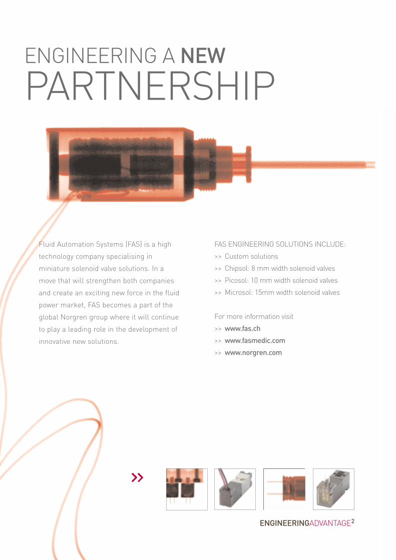
ENGINEERING A NEW
PARTNERSHIP
Fluid Automation Systems (FAS) is a high
technology company specialising in
miniature solenoid valve solutions. In a
move that will strengthen both companies
and create an exciting new force in the fluid
power market, FAS becomes a part of the
global Norgren group where it will continue
to play a leading role in the development of
innovative new solutions.
FAS ENGINEERING SOLUTIONS INCLUDE:
>> Custom solutions
>> Chipsol: 8 mm width solenoid valves
>> Picosol: 10 mm width solenoid valves
>> Microsol: 15mm width solenoid valves
For more information visit
>> www.fas.ch
>> www.fasmedic.com
>> www.norgren.com
ENGINEERINGADVANTAGE2

44 www.norgren.com/fc/en44
Herion 21023 / 21025 SeriesDirect solenoid actuated poppet valves5 and 10 mm orifice (ND)2/2, NC, GÊ, GË
WWoorrkkiinngg ffrroomm 00 bbaarr uuppSSuuiittaabbllee ffoorr mmeeddiiuumm--hhiigghh vvaaccuuuumm ddoowwnn ttoo 11..3333··1100--22 mmbbaarr··ll//ssCCoommppaacctt ddeessiiggnnFFoorr aa..cc.. ssoolleennooiidd ssyysstteemmss wwiitthh iinntteeggrraatteeddrreeccttiiffiieerr ((4400 ttoo 6600 HHzz))TThheessee ssoolleennooiidd vvaallvveess aarree AATTEEXX aapppprroovveedd
Technical dataMedium:Neutral or aggressive gases and liquidsFlow direction:Any (5 mm orifice)Defined (10 mm orifice)Mounting position:Any, but preferably with solenoid verticalFluid temperature:-25 to +80°C (NBR)-10 to +120°C (FPM = Viton), water upto +95°C-50 to +180°C (PTFE)Ambient temperature:+80°C max. (dependent on solenoid)Consult our Technical Service for use below +2°C
Switching cycles:100/min
MaterialsValve housing: brass, stainless steel1.4571/316TSeals: NBR (Perbunan), FPM (Viton),PTFE (Teflon), EPDM, FFPM/Hi-FluorInternal parts: brass, stainless steel1.4104/430F, high-purity ferritic chromesteel
Alternative modelsFor low and high ambient and fluidtemperaturesWith manual overrideFree of oil and grease for oxygen
For contaminated fluids installation of anupstream filter is recommended.
ND 10
5 G 1/4 0 ... 10 0,46 Brass NBR 0,75 1 2102300xxxx*****5 G 1/4 0 ... 10 0,46 Brass FPM 0,75 1 2102308xxxx*****5 G 1/4 0 ... 10 0,46 S/steel 1.4571/316T FPM 0,8 1 2102304xxxx*****5 G 1/4 0 ... 10 0,46 S/steel 1.4571/316T PTFE 0,8 1 2102307xxxx*****10 G 1/2 0 ... 10 1 Brass NBR 0,95 2 2102500xxxx*****10 G 1/2 0 ... 10 1 Brass FPM 0,95 2 2102503xxxx*****10 G 1/2 0 ... 10 0,75 S/steel 1.4571/316T PTFE 1 2 2102524xxxx*****10 G 1/2 0 ... 10 0,75 S/steel 1.4571/316T FPM 1 2 2102525xxxx*****
#
#‡
OOrriiffiiccee((mmmm))
PPoorrtt ssiizzee OOppeerraattiinnggpprreessssuurree ((bbaarr))
kv valuem3/h**
ND 5
MMooddeellMaterialsSeat sealHousing (without solenoid)
kg Drawingno.
* Cv (US) Ÿ kv x 1,2
xxxx Insert solenoid code from tables below. ***** Insert voltage code from table below
# ‘O’-ring FPM (Viton)‡ Slot ring PTFE (Teflon)
Other voltages on request
Options selector 2102XXX ˙˙˙˙ ˙˙˙˙˙
SSoolleennooiiddSee solenoid tables
VVoollttaaggee SSuubbssttiittuuttee24 V d.c. 0240024 V a.c. 02450110 V a.c. 11050230 V a.c. 23050
2/2 & 3/2 Solenoid operated valves
AccessoriesCable glands
EEx e 0588819 (for solenoid 42xx /46xx M20 x 1,5) 0570275EEx d 0588851 (for solenoid 46xx M20 x 1,5)EEx d, EEx e 0588925 (for solenoid 46xx 1/2-14 NPT)
ConnectorsProtection class EEx e, EEx d (ATEX), Ms nickel plated brass

45
Herion 21023 / 21025 SeriesDirect solenoid actuated poppet valves
5 and 10 mm orifice (ND)2/2, NC, GÊ, GË
16,9 – 703 – – IP00 without plug 5) -25 ... +60 DIN EN175W301-803 0,33 10 1 0800 7)
IP65 with plug 5) Form A 6)
– 18 – 75 – IP00 without plug 5) -25 ... +60 DIN EN175W301-803 0,34 11 6 3803 8)
IP65 with plug 5) Form A 6)
8,9 – 369 II2G EEx me II T4/T5 2) -40 ... +65/55 M20x1,5 6) 0,6 13 4 4270 8)
II2D IP66 T130°C– 10 43 II2G EEx me II T4/T5 2) -40 ... +65/55 M20x1,5 6) 0,6 13 7 4271 8)
II2D IP66 T130°C8,9 – 369 II2G EEx md IIC T4/T6 3) -40 ... +65/55 1/2 NPT 6) 0,8 14 4 4670 8)
II2D EEx me IIC TT4/T6 3)
IP66 T130°C– 10 43 II2G EEx md IIC T4/T6 3) -40 ... +65/55 1/2 NPT 6) 0,8 14 7 4671 8)
II2D EEx me IIC TT4/T6 3)
IP66 T130°C8,9 – 369 II2G EEx md IIC T4/T6 3) -40 ... +65/55 M20x1,5 6) 0,8 14 4 4672 8)
II2D EEx me IIC TT4/T6 3)
IP66 T130°C– 10 43 II2G EEx md IIC T4/T6 3) -40 ... +65/55 M20x1,5 6) 0,8 14 7 4673 8)
II2D EEx me IIC T6 3)
IP66 T130°C13,6 – 566 – – XP NEMA 4) -20 ... +60 4 x Flying leads 0,4 15 1 3826
4, 4X, 6, 6P, 7, 9– 15,7 – 68 – XP NEMA 4) -20 ... +60 4 x Flying leads 0,4 15 5 3827
4, 4X, 6, 6P, 7, 9
2) Category II 2 GD, EC-Type Examination Certificate KEMA 98 ATEX 4452 X3) Category II 2 GD, EC-Type Examination Certificate PTB 02 ATEX 2085 X4) CSA-LR 57643-6, FM approved, for hazardous locations: Div. 1 and 2, Class I, II,III5) Required connector type 0570275.
6) Connector/cable gland not supplied, see 'Accessories' table7) Suitable for outdoor installation only if equipped with a special protection (e.g.cubicle installation)8) This solenoid has a fuse with an appropriate rating.
Standard voltages 24 V d.c., 230 V a.c. Other voltages on request. Design acc. to VDE 0580, EN 50014/50028. 100% duty cycle.
Solenoid actuators
1 Clearance distance ~120 mm
1 2
# For solenoid dimensional drawings andcircuit diagrams, see page 96
ModelVoltage Protection class TemperaturesAmbient/fluid°C
Electrical connection kg Circuitdiagramno.#
Power consumption230 V a.c.(VA)
24 V d.c.(W)
230 V a.c.(mA)
24 V d.c.(mA)
Solenoiddrawingno.#
Protectioncategory

46 www.norgren.com/fc/en46
WWoorrkkiinngg ffrroomm 00 bbaarr uuppSSuuiittaabbllee ffoorr fflluuiidd--hhiigghh vvaaccuuuumm rraannggeeddoowwnn ttoo 11..3333··1100--22 mmbbaarr··ll//ssVVaallvvee sseeaallss iinn eeiitthheerr ddiirreeccttiioonn
Technical dataMedium:For neutral gaseous and liquid fluidsOperating pressure:0 to 50 barFlow direction:OptionalMounting position:Optional, preferably verticalFluid temperature:-25* to +80°C NBR (Perbunan)*With minus temperatures, use conditioned dry air. Ifinstalled in the open protect all connections against thepenetration of moisture
Ambient temperature:Depending on solenoid system-25 to +60, +80°CConsult our Technical Service for use below +2°C
MaterialsHousing: brassSeat seal: NBR (Perbunan)Inner part: brass, steel 1.4104/430F
AlternativemodelsSeat seal FPM (Viton), PTFE (Teflon),EPDM With manual overrideWith inductive or electromechanicallimit switches
For contaminated fluids installation ofan upstream filter is recommended.
30,5A 8 G 1/4 0 ... 15 0,87 2,1 1 1520450xxxx*****30,5A 8 G 3/8 0 ... 15 0,87 2,1 1 1520550xxxx*****30,5A 8 G 1/2 0 ... 15 0,87 2,1 1 1520650xxxx*****30,5A 12 G 3/8 0 ... 15 1,0 2,5 2 2102150xxxx*****30,5A 12 G 1/2 0 ... 15 1,0 2,5 2 2102250xxxx*****38,5A 12 G 3/8 0 ... 50 1,0 3,6 3 2101750xxxx*****38,5A 12 G 1/2 0 ... 50 1,0 3,6 3 2101850xxxx*****30,5A 12 G 1/2 0 ... 15 1,0 2,5 3 2112250xxxx*****38,5A 12 G 1/2 0 ... 50 1,0 3,6 3 2111850xxxx*****
OOrriiffiiccee((mmmm))
PPoorrtt ssiizzee OOppeerraattiinnggpprreessssuurree ((bbaarr))
kv valuem3/h**
DDrraawwiinngg nnoo..
Herion 21000 SeriesDirect acting solenoid valves8 & 12 mm orifice (ND)2/2, NC, GÊ to GË
(without solenoid)kgSSoolleennooiidd ggrroouupp MMooddeell
* Cv (US) Ÿ kv x 1,2
Other voltages on request
xxxx Insert solenoid code from tables below. ***** Insert voltage code from table below
M20 x 1,5* 0589241 (Ø 6,5...9,5 mm) EEx e 0588819M20 x 1,5 0589242 (Ø 9,0...13 mm) EEx d 05888511/2 NPT EEx d, EEx e 0588925
Cable glandsProtection class EEx e, EEx d(ATEX), Ms nickel plated brass
Cable glandsPort sizeProtection class IP65Ms nickel plated brass
Accessories
Options selector 152/21X XXXX ˙˙˙˙ ˙˙˙˙˙
SSoolleennooiiddSee solenoid tables
VVoollttaaggee SSuubbssttiittuuttee24 V d.c. 0240024 V a.c. 02450110 V a.c. 11050230 V a.c. 23050
* Included in delivery for IP65
2/2 & 3/2 Solenoid operated valves

47
Herion 21000 SeriesDirect acting solenoid valves
8 & 12 mm orifice (ND)2/2, NC, GÊ to GË
AA CC DD GG HH1 80 77 21 44 302 90 82 22 51 383 90 87 22 51 38
DDrraawwiinngg nnoo..
2
1 For solenoid dimensions see page 51
For port size, see previous page
21,4 – 891 – – IP65 with cable gland -25 ... +60 M20x1,5 1,35 1 2 1300
– 22,8 – 99 – IP65 with cable gland -25 ... +60 M20x1,5 1,35 1 6 1301–
21,4 – 891 – II2G EEx me II T4 1) -20 ... +80 M20x1,5 4) 2,0 2 4 1440EEx me II T5 1) -40 ... +60
– 22,8 – 99 II2G EEx me II T4 1) -40 ... +80 M20x1,5 4) 2,0 2 7 1441EEx me II T5 1) -40 ... +60
ModelVoltage Protection classEx- Protectioncategory
TemperaturesAmbient/fluid°C
Electricalconnection
kg Solenoiddrawingno.#
Circuitdiagram no.#
Power consumption230 V a.c.(VA)
24 V d.c.(W)
230 V a.c.(mA)
24 V d.c.(mA)
Solenoid actuators 30,5A
35,9 – 1497 – – IP65 with cable gland -25 ... +60 M20x1,5 2,5 4 2 1500Fluid max. +80
– 38,9 – 169 – IP65 with cable gland -25 ... +60 M20x1,5 2,5 4 6 1501Fluid max. +80
35,9 – 1497 – II2G EEx me IIC T5 2) -20 ... +40 M20x1,5 4) 3,6 5 2 1570
– 38,9 – 169 II2G EEx me II T5 2) -20 ... +40 M20x1,5 4) 3,6 5 6 1571
ModelVoltage Protection classEx- Protectioncategory
TemperaturesAmbient/fluid°C
Electricalconnection
kg Solenoiddrawingno.#
Circuitdiagram no.#
Power consumption230 V a.c.(VA)
24 V d.c.(W)
230 V a.c.(mA)
24 V d.c.(mA)
Solenoid actuators 38,5A
Standard voltages 24 V d.c., 230 V a.c. Other voltages on request. Design acc. to VDE 0580, EN 50014/50028. 100% duty cycle.
1) EC-Type-Examination-Certificate KEMA 03 ATEX 1016 X2) EC-Type-Examination-Certificate PTB 03 ATEX 2032 X3) Cable gland not supplied, see ‘Accessories’ table
# For solenoid dimensional drawings andcircuit diagrams, see page 51

48 www.norgren.com/fc/en48
WWoorrkkiinngg ffrroomm 00 bbaarr uuppSSuuiittaabbllee ffoorr vvaaccuuuumm ddoowwnn ttoo 11..3333mmbbaarr··ll//ssSSeeaallss iinn eeiitthheerr ffllooww ddiirreeccttiioonnSSuuiittaabbllee ffoorr sshhuutt--ooffff ssyysstteemmssHHiigghh ccoorrrroossiioonn rreessiissttaannccee ((ssttaaiinnlleessss sstteeeell))
Technical dataMedium:Neutral gases and liquids, aggressive(1.4581/316TI) gases and liquidsOperating pressure:25 bar max.Flow direction:OptionalMounting position:Optional, preferably verticalFluid temperature:-25* to +80°C (brass)-10* to +80°C (grey cast iron)-10* to +120°C (stainless steel)*With minus temperatures, use conditioned dry air.
Ambient temperature:Depending on solenoid system-25 to +80°C (brass)-10 to +80°C (grey cast iron,1.4581/316TI)Consult our Technical Service for use below +2°C
Electrical connection:M20 x 1,5 and 1/2 NPT
MaterialsHousing: brass, grey cast iron, stainlesssteel (1.4581/316TI)Seat seal: NBR (Perbunan), FPM (Viton)Inner part: brass, stainless steel
Alternative modelsInner part material 1.4571/316TSeat seal material FPM (Viton), EPDMManual override with and without detentInductive and electromechanical limitswitches
For contaminated fluids installation of anupstream filter is recommended.
30,5A 12 G 1/2 NC 0 ... 15 1,4 Brass NBR 3,0 1 2323120xxxx*****38,5A 12 G 1/2 NC 0 ... 25 1,2 Brass NBR 4,3 2 2324120xxxx*****38,5A 20 G 3/4 NC 0 ... 10 6,5 Grey cast iron NBR 5,5 3 2323420xxxx*****47,5A 20 G 3/4 NC 0 ... 25 6,5 Grey cast iron NBR 7,5 4 2324420xxxx*****38,5A 25 G 1 NC 0 ... 6 9,0 Grey cast iron NBR 6,0 3 2322520xxxx*****47,5A 25 G 1 NC 0 ... 10 9,0 Grey cast iron NBR 8,0 4 2323620xxxx*****47,5A 25 G 1 NC 0 ... 25 9,0 Grey cast iron NBR 8,0 4 2324620xxxx*****47,5B 40 G 1Ë NC 0 ... 10 16,5 Grey cast iron NBR 9,5 5 2323820xxxx*****47,5B 40 G 2 NC 0 ... 10 16,5 Grey cast iron NBR 9,5 5 2323920xxxx*****30,5A 12 G 1/2 NO 0 ... 15 1,4 Brass NBR 3,0 1 2326120xxxx*****38,5A 12 G 1/2 NO 0 ... 25 1,2 Brass NBR 4,3 2 2327120xxxx*****38,5A 20 G 3/4 NO 0 ... 10 6,5 Grey cast iron NBR 5,5 3 2326420xxxx*****47,5A 20 G 3/4 NO 0 ... 25 6,5 Grey cast iron NBR 7,5 4 2327420xxxx*****38,5A 25 G 1 NO 0 ... 6 9,0 Grey cast iron NBR 6,0 3 2325520xxxx*****47,5A 25 G 1 NO 0 ... 10 9,0 Grey cast iron NBR 8,0 4 2326620xxxx*****47,5A 25 G 1 NO 0 ... 25 9,0 Grey cast iron NBR 8,0 4 2327620xxxx*****47,5B 40 G 1Ë NO 0 ... 10 16,5 Grey cast iron NBR 9,5 5 2326820xxxx*****47,5B 40 G 2 NO 0 ... 10 16,5 Grey cast iron NBR 9,5 5 2326920xxxx*****
Herion 23200 SeriesDirect acting solenoid valves12 to 40 mm orifice (ND)2/2, NC/NO, GË to G2
38,5A 15 G 1/2 NC 0 ... 10 6,0 S/steel 1.4581/316TI FKM 6,0 3 2324157xxxx*****38,5A 25 G 1 NC 0 ... 10 6,5 S/steel 1.4581/316TI FKM 6,0 3 2322557xxxx*****
* Cv (US) Ÿ kv x 1,2
Other voltages on request
xxxx Insert solenoid code from tables below. ***** Insert voltage code from table below
For aggressive fluids
Options selector 232XXXX ˙˙˙˙ ˙˙˙˙˙
SSoolleennooiiddSee solenoid tables
VVoollttaaggee SSuubbssttiittuuttee24 V d.c. 0240024 V a.c. 02450110 V a.c. 11050230 V a.c. 23050
Accessories
M20 x 1,5* 0589241 (Ø 6,5 ... 9,5 mm) EEx e 0588819M20 x 1,5 0589242 (Ø 9,0 ... 13 mm) EEx d 05888511/2 NPT EEx d, EEx e 0588925
Cable glandsProtection class EEx e, EEx d (ATEX),Ms nickel plated brass
Cable glandsPort sizeProtection class IP65Ms nickel plated brass
OOrriiffiiccee((mmmm))
PPoorrtt ssiizzee OOppeerraattiinnggpprreessssuurree ((bbaarr))
kv valuem3/h**
MMaatteerriiaallssHHoouussiinngg SSeeaatt sseeaall
DDrraawwiinnggnnoo..
SSoolleennooiiddggrroouupp
kkgg MMooddeellFFuunnccttiioonn
OOrriiffiiccee((mmmm))
PPoorrttssiizzee
OOppeerraattiinnggpprreessssuurree ((bbaarr))
kv valuem3/h**
MMaatteerriiaallssHHoouussiinngg SSeeaatt sseeaall
DDrraawwiinnggnnoo..
SSoolleennooiiddggrroouupp
kkgg MMooddeellFFuunnccttiioonn
* Included in delivery for IP65
2/2 & 3/2 Solenoid operated valves

49
Herion 23200 SeriesDirect acting solenoid valves
12 to 40 mm orifice (ND)2/2, NC/NO, GË to G2
21,4 – 891 – – IP65 with cable gland -25 ... +60 M20x1,5 1,35 1 2 1300
– 22,8 – 99 – IP65 with cable gland -25 ... +60 M20x1,5 1,35 1 6 1301–
21,4 – 891 – II2G EEx me II T4 1) -20 ... +80 M20x1,5 3) 2,0 2 4 1440EEx me II T5 1) -40 ... +60
– 22,8 – 99 II2G EEx me II T4 1) -40 ... +80 M20x1,5 3) 2,0 2 7 1441EEx me II T5 1) -40 ... +60
35,9 – 1497 – – IP65 with cable gland -25 ... +60 M20x1,5 2,5 4 2 1500Fluid max. +80
– 38,9 – 169 – IP65 with cable gland -25 ... +60 M20x1,5 2,5 4 6 1501Fluid max. +80
35,9 – 1497 – II2G EEx me IIC T5 2) -20 ... +40 M20x1,5 4) 3,6 5 2 1570
– 38,9 – 169 II2G EEx me II T5 2) -20 ... +40 M20x1,5 4) 3,6 5 6 1571
ModelVoltage Protection classProtectioncategory
TemperaturesAmbient/fluid°C
Electricalconnection
kg Solenoiddrawingno.#
Circuitdiagram no.#
Power consumption230 V a.c.(VA)
24 V d.c.(W)
230 V a.c.(mA)
24 V d.c.(mA)
Solenoid actuators 30,5A
21,4 – 891 – II2G EEx EEX d IIC T4 2) -40 ... +60 1/2 NPT 4) 3,3 3 2 1480II2D IP66 T90°C
– 22,8 – 99 II2G EEx EEX d IIC T4 2) -40 ... +60 1/2 NPT 4) 3,3 3 6 1481II2D IP66 T90°C
ModelVoltage Protection classProtectioncategory
TemperaturesAmbient/fluid°C
Electricalconnection
kg Solenoiddrawingno.#
Circuitdiagram no.#
Power consumption230 V a.c.(VA)
24 V d.c.(W)
230 V a.c.(mA)
24 V d.c.(mA)
Solenoid actuators 30,5B
35,9 – 1497 – II2G EEx d IIC T4 2) -40 ... +60 1/2 NPT 4) 4,2 3 2 1680II2D IP66 T105°C
– 38,9 – 169 II2G EEx d IIC T4 2) -40 ... +60 1/2 NPT 4) 4,2 3 6 1681II2D IP66 T105°C
ModelVoltage Protection classProtectioncategory
TemperaturesAmbient/fluid°C
Electricalconnection
kg Solenoiddrawingno.#
Circuitdiagram no.#
Power consumption230 V a.c.(VA)
24 V d.c.(W)
230 V a.c.(mA)
24 V d.c.(mA)
Solenoid actuators 38,5B
ModelVoltage Protection classProtectioncategory
TemperaturesAmbient/fluid°C
Electricalconnection
kg Solenoiddrawingno.#
Circuitdiagram no.#
Power consumption230 V a.c.(VA)
24 V d.c.(W)
230 V a.c.(mA)
24 V d.c.(mA)
Solenoid actuators 38,5A
52,5 – 2181 – IP65 with connector 4) -40 ... +40° M20x1,5 4,6 6 2 1600Fluid 80° max.
– 56,4 – 245 IP65 with connector 4) -40 ... +40° M20x1,5 4,6 6 6 1601Fluid 80° max.
ModelVoltage Protection class TemperaturesAmbient/fluid°C
Electricalconnection
kg Solenoiddrawingno.#
Circuitdiagram no.#
Power consumption230 V a.c.(VA)
24 V d.c.(W)
230 V a.c.(mA)
24 V d.c.(mA)
Solenoid actuators 47,5A
62,5 – 2606 – IP65 with connector 4) -40...+40° M20x1,5 9,7 7 2 1700Fluid 80° max.
– 58,9 – 256 IP65 with connector 4) -40...+40° M20x1,5 9,7 7 6 1701Fluid 80° max.
ModelVoltage Protection class TemperaturesAmbient/fluid°C
Electricalconnection
kg Solenoiddrawingno.#
Circuitdiagram no.#
Power consumption230 V a.c.(VA)
24 V d.c.(W)
230 V a.c.(mA)
24 V d.c.(mA)
Solenoid actuators 47,5B
Standard voltages 24 V d.c., 230 V a.c. Other voltages on request. Design acc. to VDE 0580, EN 50014/50028. 100% duty cycle.1) EC-Type-Examination-Certificate KEMA 03 ATEX 1016 X2) EC-Type-Examination-Certificate EXAM PTB 03 ATEX 2032 X3) EC-Type-Examination-Certificate PTP ATEX 2032 X4) Cable gland not supplied, see ‘Accessories’ table
# For solenoid dimensional drawings andcircuit diagrams, see page 51

50
Herion 23200 SeriesDirect acting solenoid valves12 to 40 mm orifice (ND)2/2, NC/NO, GË to G2
CC
1 902 96
DDrraawwiinngg nnoo..
AA CC DD GG
3 118 120 50,5 664 118 125 50,5 665 180 179 79 94
DDrraawwiinngg nnoo..
1 2
3 4 5
2
1 For solenoid dimensions see page 51
For port size, see page 48
2/2 & 3/2 Solenoid operated valves

51
Circuit diagrams
2
4
6
7
1 2
4 5
3
6 7
Solenoid dimensional drawings
52 www.norgren.com/fc/en52
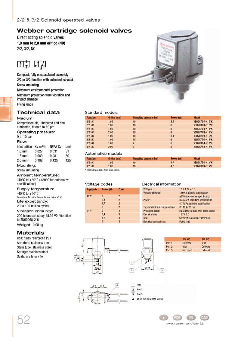
2/2 NC 1,00 10 3,4 VSD2CAD4-K19*K2/2 NC 1,00 10 6 VSD2CAD4-K13*K2/2 NC 1,60 10 6 VSD2CAG4-K13*K2/2 NC 2,00 10 6 VSD2CAH4-K13*K3/2 NC 1,00 10 3,4 VSD7CAD4-K19*K3/2 NC 1,00 10 6 VSD7CAD4-K13*K3/2 NC 1,60 7 6 VSD7CAG4-K13*K3/2 NC 2,00 7 6 VSD7CAH4-K13*K
CCoommppaacctt,, ffuullllyy eennccaappssuullaatteedd aasssseemmbbllyy22//22 oorr 33//22 ffuunnccttiioonn wwiitthh ccoolllleecctteedd eexxhhaauussttSSccrreeww mmoouunnttiinnggMMaaxxiimmuumm eennvviirroonnmmeennttaall pprrootteeccttiioonnMMaaxxiimmuumm pprrootteeccttiioonn ffrroomm vviibbrraattiioonn aannddiimmppaacctt ddaammaaggeeFFllyyiinngg lleeaaddss
Standard modelsMMooddeellOOrriiffiiccee ((mmmm))FFuunnccttiioonn OOppeerraattiinngg pprreessssuurree ((bbaarr)) PPoowweerr ((WW))
2/2 NC 1,00 10 4,7 VSD2CAD4-K1V*K3/2 NC 1,00 10 4,7 VSD7CAD4-K1V*K
Automotive modelsMMooddeellOOrriiffiiccee ((mmmm))FFuunnccttiioonn OOppeerraattiinngg pprreessssuurree ((bbaarr)) PPoowweerr ((WW))
Voltage codes
12 V 2 23,4 24,7 26 2
24 V 2 33,4 34,7 36 3
SSuuppppllyy dd..cc.. PPoowweerr ((WW)) CCooddee
Electrical informationVoltages: 12 V & 24 V d.c.Voltage tolerance: ±10% Standard specification
±25% Automotive specificationPower: 3,4 & 6 W Standard specification
4,7 W Automotive specificationTypical electrical response time: On 10 to 20 msProtection class: IP65 (DIN 40 050) with cable clampElectrical duty: 100% E.D.Coil: Screwed to customer interfaceElectrical connections: Flying lead
Webber cartridge solenoid valvesDirect acting solenoid valves1,0 mm to 2,0 mm orifice (ND)2/2, 3/2, NC
* Insert voltage code from table below.
22//22 NNCC 33//22 NNCCPort 1 Delivery InletPort 2 Inlet DeliveryPort 3 Not Used Exhaust
Technical dataMedium:Compressed air, lubricated and nonlubricated, filtered to 50 µmOperating pressure:0 to 10 barFlow:Inlet orifice Kv m3/h NFPA Cv l/min1,0 mm 0,027 0,031 311,6 mm 0,069 0,08 802,0 mm 0,108 0,125 125Mounting:Screw mounting Ambient temperature:-40°C to +50°C (+80°C for automotivespecifications)Supply temperature:-40°C to +90°CConsult our Technical Service for use below +2°C
Life expectancy:20 to 100 million cyclesVibration immunity:200 hours salt spray; UL94 V0; Vibrationto EN60068-2-6Weight: 0,08 kg
MaterialsCoil: glass reinforced PETArmature: stainless ironStem tube: stainless steelSprings: stainless steelSeals: nitrile or viton
4
3
2
1 Port 1
Port 2
Port 3
Ø 4,5 mm to suit M4 screws
2/2 & 3/2 Solenoid operated valves

53
TTwwiinn ssoolleennooiidd ooffffeerrss dduuaall ccoonnttrrooll TTwwoo 22//22 nnoorrmmaallllyy cclloosseedd vvaallvveessccoommbbiinneedd iinn aa ssiinnggllee uunniittIInntteeggrraall ppuusshh iinn ffiittttiinnggss ffoorr ssiimmpplleeaanndd rraappiidd iinnssttaallllaattiioonnIIddeeaall ffoorr aapppplliiccaattiioonnss rreeqquuiirriinnggiinnffllaattiioonn aanndd ddeeffllaattiioonn ccoonnttrrooll
Technical dataMedium:Compressed air, filtered, lubricatedand non-lubricated Operating pressure:Up to 10 bar Flow:29 l/min Ambient temperature:-20°C to +50°C Consult our Technical Service for use below +2°C
Weight: 200 g
MaterialsBase: Hostaform plastic resinCoil: glass reinforced thermoplasticArmature: stainless ironStem tube: stainless steelSprings: stainless steelSeals: nitrile rubber
AlternativemodelsFlying lead coils
Webber Excel 22 Dual controlTwin 22 mm direct acting solenoid valves4 mm, 6 mm push-in
Electrical details for solenoid operatorsVoltage tolerance: ±10%Power consumption: 2 WElectrical duty: 100 % E.D.Electrical connections: 3 flat pin (Industrial standard)Manual override: NoneProtection class: IP 65 (DIN 40 050) with connector plug fitted
***Insert voltage code from table below.
Voltage codes
12 V d.c. 12J24 V d.c. 50/60 Hz 13J
For details of connector plugs and indicators please contact our Technical Service
2/2 NC 1,0 10 2 W VSD2DAD1-A1***MMooddeellOOrriiffiiccee ((mmmm))FFuunnccttiioonn OOppeerraattiinngg pprreessssuurree ((bbaarr)) PPoowweerr ((WW//VVAA))
SSuuppppllyy dd..cc.. CCooddee
www.norgren.com/fc/en53

54 www.norgren.com/fc/en54
CCoommppaacctt,, 2222 mmmm ssoolleennooiidd vvaallvveessVVeerrttiiccaall oorr hhoorriizzoonnttaall mmoouunnttiinngg ooppttiioonnssCCoommppaattiibbllee wwiitthh mmuullttiippllee iinnkkss aannddfflluusshhiinngg mmeeddiiaassPPrroovveenn rreelliiaabbiilliittyy
Technical dataMedium:Methyl ethyl ketoneEthyl acetateWater/glycolEthanolMethanolAcetone (40° maximum)Operation:Poppet valve, direct actuated with springreturn.Operating pressure:-0,5 to 4,5 bar (max.)Flow:√ 100 c.c./min at 0,5 bar differentialAmbient temperature:+50°CSupply temperature:+55°CConsult our Technical Service for use below +2°C
Life expectancy:Typically in excess of 10 million cyclesWeight: 0,09 kg (without plug)
MaterialsValve base: DelrinCoil: glass reinforced thermoplastic mouldedStem tube: stainless steelArmature: stainless steelSprings: stainless steel wireSeals: EPDM
Alternative models2 wire electrical flying leadsTable B Din 43650 electrical connectionsAlternative materialsManifolds
3/2 NC & 3/2 Change over – side ported 1,5 -0,5 ... 4,5 6 90-19371/PC3/2 NC & 3/2 Change over – interface base 1,5 -0,5 ... 4,5 6 90-19375/PC2/2 Change over – side ported 1,5 -0,5 ... 4,5 6 90-19372/PC2/2 Change over – interface base 1,5 -0,5 ... 4,5 6 90-19376/PC
MMooddeellOOrriiffiiccee((mmmm))
DDeessccrriippttiioonn OOppeerraattiinngg pprreessssuurree((bbaarr))
PPoowweerr ((WW))
Webber ink jet valveDirect acting solenoid valvesManifold mounted1,5 mm orifice (ND)2/2, 3/2
Electrical informationVoltage: 24 V d.c. ± 10%d.c. Power: 6 WTypical electrical response time: On 10 to 20 ms
Off 5 to 10 msProtection class: IP 65 (DIN 40 050) with connector plug fittedElectrial duty: 100% (Continuously rated)Coil: 22 mm removable encapsulated; 3 pin
2/2 & 3/2 Solenoid operated valves

55
Webber ink jet valveDirect acting solenoid valves
Manifold mounted1,5 mm orifice (ND)
2/2, 3/2
90-19376/PC2/2 N/C
90-19372/PC2/2 N/C
90-19375/PC3/2 NC & 3/2 Changeover
90-19371/PC3/2 NC & 3/2 Changeover
2 x Ø 3,3 mm mounting holes tosuit countersunk head screws
3
2
1 Port 1
Port 2 area
2 x Ø 3,3 mm mounting holes to suit countersunk head screws 3
2
1 Port 1
Port 2
2 x Ø 3,5 mm mounting holes to suit pan head screws
4
3
2
1 Port 1
Port 2 area
2 x Ø 3,3 mm mounting holes to suit countersunk head screws
Port 3 4
3
2
1 Port 1
Port 2
2 x Ø 3,5 mm mounting holes to suit pan head screws
Port 3

56 www.norgren.com/fc/en56
2222 mmmm mmiinniiaattuurree bbaassee ppoorrtteedd ssoolleennooiiddvvaallvveessNNoorrmmaallllyy cclloosseedd aanndd nnoorrmmaallllyy ooppeenn oonntthhee ssaammee mmaanniiffoollddCCoolllleecctteedd eexxhhaauussttIInntteerrcchhaannggeeaabbllee ccooiillss
Technical dataMedium:Compressed air, filtered, lubricated and non-lubricatedLight oil, water and other non-corrosiveliquids and gasesOperating pressure:0 to 5 bar (max.)Flow:Inlet orifice Kv m3/h NFPA Cv l/min1,8 mm 0,079 0,091 90Mounting:M4 threaded holes in manifold on centresAmbient temperature:-20°C to +50°CSupply temperature:-20°C to +70°CConsult our Technical Service for use below +2°C
Life expectancy:Typically in excess of 10 million cyclesWeight: N x 0,19 kg (N = number ofstations)
MaterialsValve base: moulded PBTCoil: glass reinforced thermoplasticManifold: anodised aluminiumArmature: stainless ironStem tube: stainless steelSprings: stainless steelSeals: nitrile rubber
Alternative modelsVacuum operation2 wire electrical flying leadsTable B DIN 43650 Electrical connectors
Webber base ported mini valvesDirect acting solenoid valvesManifold mounted1,8 mm orifice (ND)3/2, NC/NO, GÊ inlet & exhaust, GÂ outlet
Electrical informationVoltage tolerance ±10% as standardd.c. Power 7,5 W (6 W for 24 V d.c. high power coils)Typical electrical response time On 10 to 20 ms
Off 5 to 10 msProtection class IP 65 (DIN 40 050) with connector plug fittedElectrical duty 100% (Continuously rated)Coil 22 mm removable encapsulatedElectrical connections 3 flat pin (Industrial standard)Connector plug Plug available
3/2 NC 1,8 5 6 or 7,5 None VSD7P5U1-A18003/2 NO 1,8 5 6 or 7,5 None VSD6P5U1-A1800
**
MMooddeellOOrriiffiiccee((mmmm))
FFuunnccttiioonn OOppeerraattiinngg pprreessssuurree((bbaarr))
PPoowweerr ((WW)) MMaannuuaall oovveerrrriiddee
Voltage codes
12 V d.c. 82J 7,5 QM/48/82J/2124 V d.c. 83J 6 QM/48/83J/21110 V d.c. 89J 7,5 QM/48/87J/21
MMooddeellSSuuppppllyy dd..cc..
PPoowweerr ((WW))VVoollttaaggee
24 V a.c. 50/60 Hz 84J 12/8 90-19517/CW115 V a.c. 50/60 Hz 88J 12/8 90-19517/CG230 V a.c. 50/60 Hz 89J 12/8 90-19517/PB
MMooddeellSSuuppppllyy aa..cc..
CCooddee
CCooddee
PPoowweerr ((VVAA))VVoollttaaggee
Manifolds
1 G1/8 Base ported 810880012 G1/8 Base ported 810880023 G1/8 Base ported 810880034 G1/8 Base ported 810880045 G1/8 Base ported 810880056 G1/8 Base ported 810880067 G1/8 Base ported 810880078 G1/8 Base ported 81088008
MMooddeellPPoorrtt ssiizzeeNNoo.. ooff ssttaattiioonnss PPoorrttiinngg
*Please order plugs seperately using the model numbers from the Voltage code tables below
* a.c. coils are supplied with a rectified plug and must be used with this plug
2/2 & 3/2 Solenoid operated valves

57
Webber base ported mini valvesDirect acting solenoid valves
Manifold mounted1,8 mm orifice (ND)
3/2, NC/NO, GÊ inlet & exhaust, GÂ outlet
Manifolds
Single station 45 35Multiple stations 25 x (N-1) + 45 25 x (N-1) + 35
AA BBMMaanniiffoolldd
N = number of stations
58 www.norgren.com/fc/en58
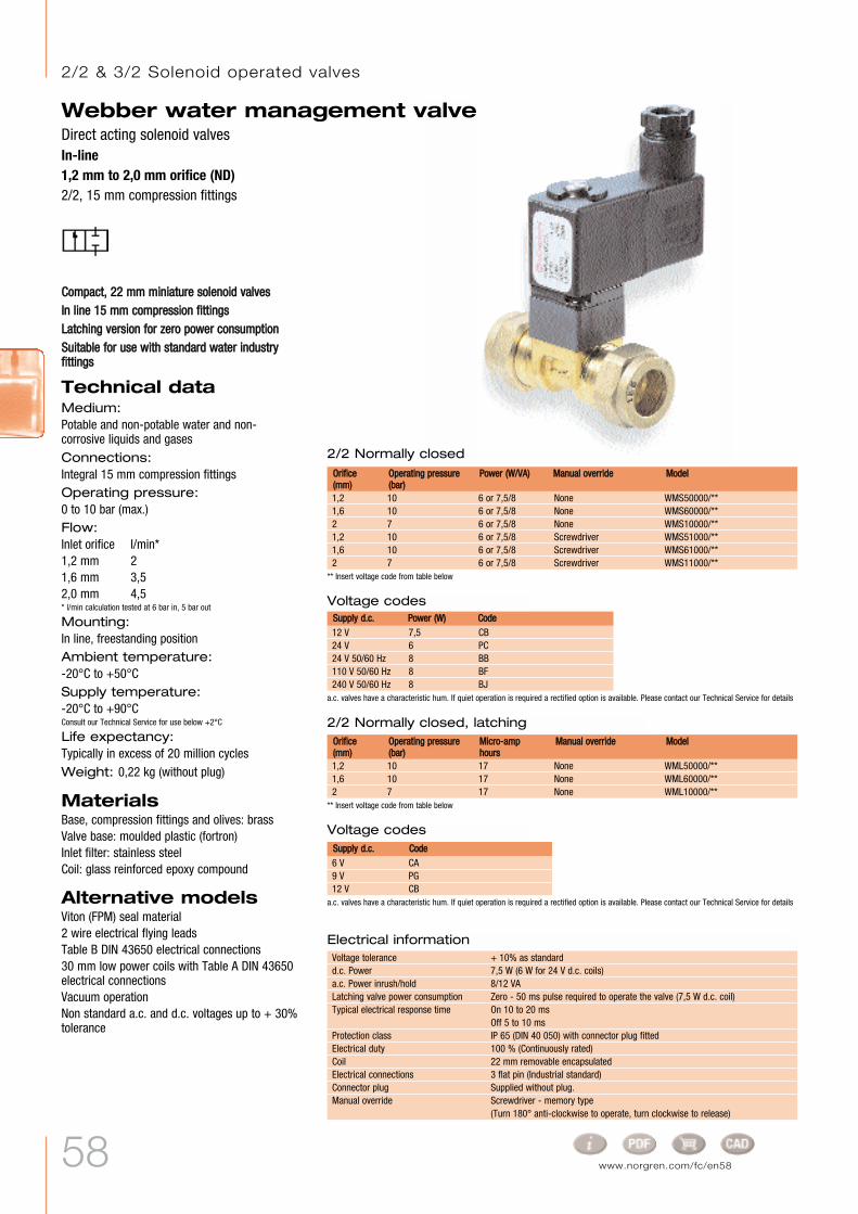
CCoommppaacctt,, 2222 mmmm mmiinniiaattuurree ssoolleennooiidd vvaallvveessIInn lliinnee 1155 mmmm ccoommpprreessssiioonn ffiittttiinnggssLLaattcchhiinngg vveerrssiioonn ffoorr zzeerroo ppoowweerr ccoonnssuummppttiioonnSSuuiittaabbllee ffoorr uussee wwiitthh ssttaannddaarrdd wwaatteerr iinndduussttrryyffiittttiinnggss
Technical dataMedium:Potable and non-potable water and non-corrosive liquids and gasesConnections:Integral 15 mm compression fittings Operating pressure:0 to 10 bar (max.) Flow:Inlet orifice l/min*1,2 mm 21,6 mm 3,52,0 mm 4,5* l/min calculation tested at 6 bar in, 5 bar out
Mounting:In line, freestanding positionAmbient temperature:-20°C to +50°CSupply temperature:-20°C to +90°CConsult our Technical Service for use below +2°C
Life expectancy:Typically in excess of 20 million cyclesWeight: 0,22 kg (without plug)
MaterialsBase, compression fittings and olives: brassValve base: moulded plastic (fortron)Inlet filter: stainless steelCoil: glass reinforced epoxy compound
Alternative modelsViton (FPM) seal material2 wire electrical flying leadsTable B DIN 43650 electrical connections30 mm low power coils with Table A DIN 43650electrical connectionsVacuum operationNon standard a.c. and d.c. voltages up to + 30%tolerance
2/2 Normally closed
1,2 10 6 or 7,5/8 None WMS50000/**1,6 10 6 or 7,5/8 None WMS60000/**2 7 6 or 7,5/8 None WMS10000/**1,2 10 6 or 7,5/8 Screwdriver WMS51000/**1,6 10 6 or 7,5/8 Screwdriver WMS61000/**2 7 6 or 7,5/8 Screwdriver WMS11000/**
MMooddeellOOrriiffiiccee((mmmm))
OOppeerraattiinngg pprreessssuurree((bbaarr))
PPoowweerr ((WW//VVAA)) MMaannuuaall oovveerrrriiddee
2/2 Normally closed, latching
Webber water management valveDirect acting solenoid valvesIn-line1,2 mm to 2,0 mm orifice (ND)2/2, 15 mm compression fittings
** Insert voltage code from table below
** Insert voltage code from table below
1,2 10 17 None WML50000/**1,6 10 17 None WML60000/**2 7 17 None WML10000/**
MMooddeellOOrriiffiiccee((mmmm))
OOppeerraattiinngg pprreessssuurree((bbaarr))
MMiiccrroo--aammpphhoouurrss
MMaannuuaall oovveerrrriiddee
Voltage codes
12 V 7,5 CB24 V 6 PC24 V 50/60 Hz 8 BB110 V 50/60 Hz 8 BF240 V 50/60 Hz 8 BJ
Electrical informationVoltage tolerance + 10% as standardd.c. Power 7,5 W (6 W for 24 V d.c. coils)a.c. Power inrush/hold 8/12 VA Latching valve power consumption Zero - 50 ms pulse required to operate the valve (7,5 W d.c. coil)Typical electrical response time On 10 to 20 ms
Off 5 to 10 msProtection class IP 65 (DIN 40 050) with connector plug fittedElectrical duty 100 % (Continuously rated)Coil 22 mm removable encapsulatedElectrical connections 3 flat pin (Industrial standard)Connector plug Supplied without plug. Manual override Screwdriver - memory type
(Turn 180° anti-clockwise to operate, turn clockwise to release)
SSuuppppllyy dd..cc.. PPoowweerr ((WW)) CCooddee
Voltage codes
6 V CA9 V PG12 V CB
SSuuppppllyy dd..cc.. CCooddee
a.c. valves have a characteristic hum. If quiet operation is required a rectified option is available. Please contact our Technical Service for details
a.c. valves have a characteristic hum. If quiet operation is required a rectified option is available. Please contact our Technical Service for details
2/2 & 3/2 Solenoid operated valves

59
Webber water management valveDirect acting solenoid valves
In-line1,2 mm to 2,0 mm orifice (ND)2/2, 15 mm compression fittings
2
1 Inlet
Outlet

60 www.norgren.com/fc/en60
M5 3/2 NC Sol/spring 0,13 Single M/48/MAZ***M5 3/2 NC Sol/spring 0,31 ... 0,9 Manifold DM/48/MAZ***/T#G1/8 3/2 NC Sol/spring 0,14 Single M/49/MAZ***G1/8 3/2 NC Sol/spring 0,31 ... 0,9 Manifold DM/49/MAZ***/T#
MMiinniiaattuurree 2222 mmmm nnoorrmmaallllyy ooppeennaanndd nnoorrmmaallllyy cclloosseedd mmooddeellssSSuubb--bbaassee mmoouunntteedd aanndd mmaanniiffoollddmmoouunntteedd -- ccoommppaacctt aannddccoonnvveenniieennttMMaannuuaall oovveerrrriiddee aass ssttaannddaarrdd
Technical dataMedium:Compressed air, filtered, lubricatedand non lubricated. Operating pressure:0 to 10 bar Flow:Orifice l/min1,0 mm 301,6 mm 77 Ambient temperature:-20°C to +50°C. Consult our Technical Service for use below +2°C
MaterialsCoil: glass reinforced thermo plasticManual override base: glassreinforced nylonArmature: stainless ironSub-base: aluminiumSeals: nitrileTube & spring: stainless steel
Alternativemodels2/2 N/C modelsN/O modelsPush button manual operators15 mm models32 mm modelsFlying lead coilsVitonContact our Technical Service fordetails.
M/48/MDZ***DM/48/MDZ***/T#M/49/MDZ***DM/49/MDZ***/T#
Service kits are not available for these valves.*** Insert voltage codes from table below.# No. of stations up to 6 maximum.Order connector plugs separately.
Voltage codes
Electrical details for solenoid operators
These coils are supplied complete with a rectified plug and must be used only with this plug.
Voltage tolerance: ±10%Rating: 100% E.D.Inlet orifice: 1,0 mm or 1,6 mmElectrical connection: 22 mm Industrial Standard*Protection class: IP 65 (DIN 40 050) with plug fittedCable entry: Pg 9Manual override: Screwdriver operated, memory type, standard
*Form B electrical connections available - please refer to data sheets.
Size Function kg Mounting Model1,0 mm orifice (low power) 1,6 mm orifice
Actuation
1,0 mm orifice (low power) 1,6 mm orificeVoltageCode Power Coil Code Power Coil
12 V d.c. 12J 2 W QM/48/12J/2124 V d.c. 13J 2 W QM/48/13J/2124 V 50/60 Hz 14J 4/2,5 VA QM/48/14J/21110/120 V 50/60 Hz 18J 4/2,5 VA QM/48/18J/21220/240 V 50/60 Hz 19J 6/5 VA QM/48/19J/21
82J 7,5 W QM/48/82J/2183J 6 W QM/48/83J/2184J 12/8 VA QM/48/84J/2188J 12/8 VA QM/48/88J/2189J 12/8 VA QM/48/89J/21
24 V 50/60 Hz 4/2,5 14J 90-19517/VE 12/8 84J 90-19517/CW115 V 50/60 Hz 4/2,5 18J 90-19517/CG 12/8 88J 90-19517/CG230 50/60 Hz 12/8 89J 90-19517/PB
SSuuppppllyy aa..cc..PPoowweerr ((VVAA))11,,00 mmmm oorriiffiiccee ((llooww ppoowweerr)) 11,,66 mmmm oorriiffiiccee
CCooddee PPoowweerr ((VVAA)) CCooddee
a.c. valves have a characteristic hum. If quiet operation is required please refer to table below for our rectified coil and plug option.
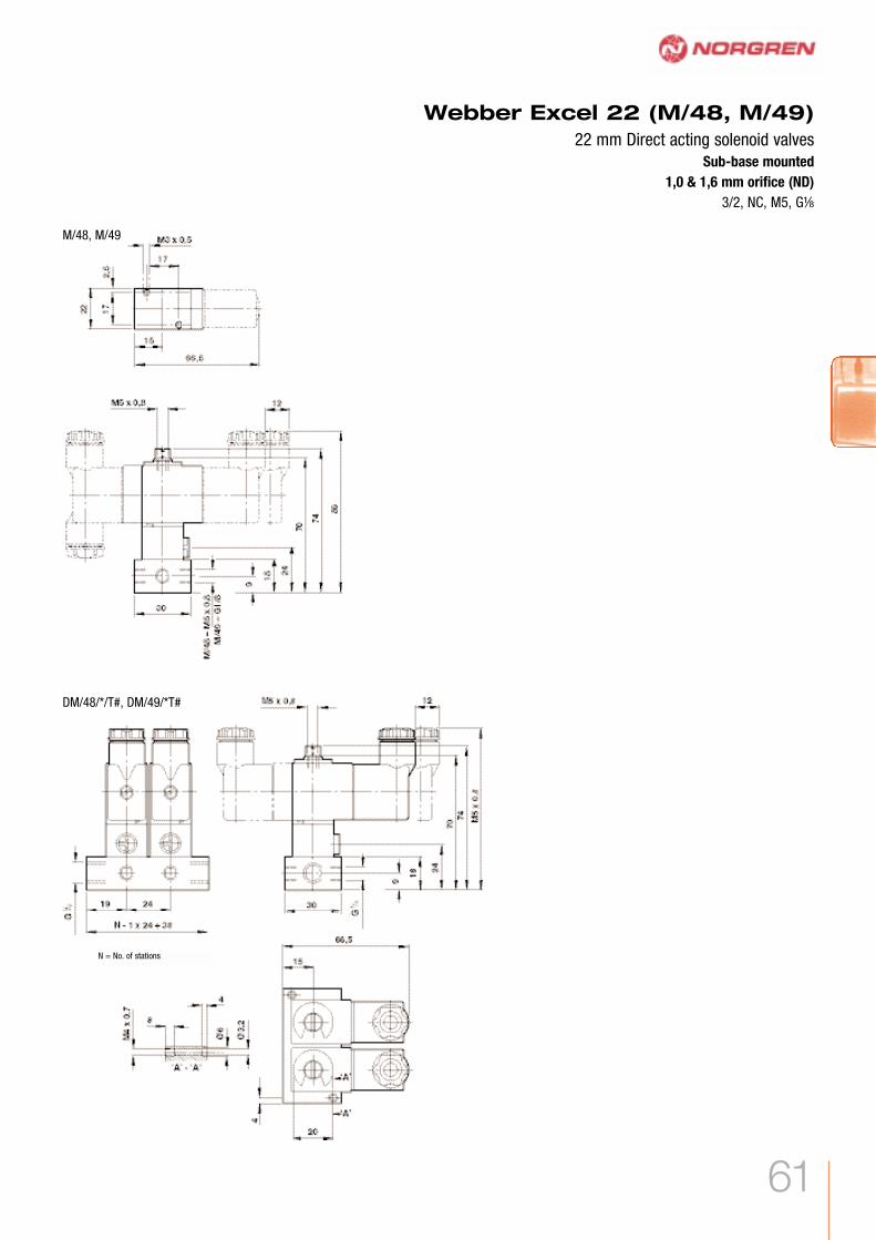
Webber Excel 22 (M/48, M/49)22 mm Direct acting solenoid valvesSub-base mounted1,0 & 1,6 mm orifice (ND)3/2, NC, M5, GÂ
Coil Coil
Rectified plug option
2/2 & 3/2 Solenoid operated valves
For details of connector plugs and indicators please contact our Technical Service
61
Webber Excel 22 (M/48, M/49)22 mm Direct acting solenoid valves
Sub-base mounted1,0 & 1,6 mm orifice (ND)
3/2, NC, M5, GÂ
M/48, M/49
DM/48/*/T#, DM/49/*T#
N = No. of stations
62 www.norgren.com/fc/en62
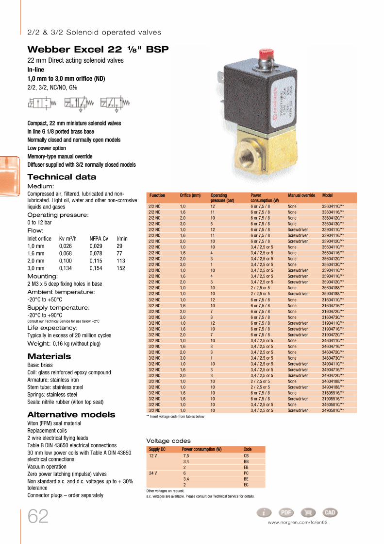
CCoommppaacctt,, 2222 mmmm mmiinniiaattuurree ssoolleennooiidd vvaallvveessIInn lliinnee GG 11//88 ppoorrtteedd bbrraassss bbaasseeNNoorrmmaallllyy cclloosseedd aanndd nnoorrmmaallllyy ooppeenn mmooddeellssLLooww ppoowweerr ooppttiioonnMMeemmoorryy--ttyyppee mmaannuuaall oovveerrrriiddeeDDiiffffuusseerr ssuupppplliieedd wwiitthh 33//22 nnoorrmmaallllyy cclloosseedd mmooddeellss
Technical dataMedium:Compressed air, filtered, lubricated and non-lubricated. Light oil, water and other non-corrosiveliquids and gasesOperating pressure:0 to 12 barFlow:Inlet orifice Kv m3/h NFPA Cv l/min1,0 mm 0,026 0,029 291,6 mm 0,068 0,078 772,0 mm 0,100 0,115 1133,0 mm 0,134 0,154 152Mounting:2 M3 x 5 deep fixing holes in baseAmbient temperature:-20°C to +50°CSupply temperature:-20°C to +90°CConsult our Technical Service for use below +2°C
Life expectancy:Typically in excess of 20 million cyclesWeight: 0,16 kg (without plug)
MaterialsBase: brassCoil: glass reinforced epoxy compound Armature: stainless ironStem tube: stainless steelSprings: stainless steelSeals: nitrile rubber (Viton top seat)
Alternative modelsViton (FPM) seal materialReplacement coils 2 wire electrical flying leadsTable B DIN 43650 electrical connections30 mm low power coils with Table A DIN 43650electrical connectionsVacuum operationZero power latching (impulse) valvesNon standard a.c. and d.c. voltages up to + 30%toleranceConnector plugs – order separately
Webber Excel 22 Â" BSP22 mm Direct acting solenoid valvesIn-line1,0 mm to 3,0 mm orifice (ND)2/2, 3/2, NC/NO, GÂ
2/2 NC 1,0 12 6 or 7,5 / 8 None 33604110/**2/2 NC 1,6 11 6 or 7,5 / 8 None 33604116/**2/2 NC 2,0 10 6 or 7,5 / 8 None 33604120/**2/2 NC 3,0 5 6 or 7,5 / 8 None 33604130/**2/2 NC 1,0 12 6 or 7,5 / 8 Screwdriver 33904110/**2/2 NC 1,6 11 6 or 7,5 / 8 Screwdriver 33904116/**2/2 NC 2,0 10 6 or 7,5 / 8 Screwdriver 33904120/**2/2 NC 1,0 10 3,4 / 2,5 or 5 None 35604110/**2/2 NC 1,6 4 3,4 / 2,5 or 5 None 35604116/**2/2 NC 2,0 3 3,4 / 2,5 or 5 None 35604120/**2/2 NC 3,0 1 3,4 / 2,5 or 5 None 35604130/**2/2 NC 1,0 10 3,4 / 2,5 or 5 Screwdriver 35904110/**2/2 NC 1,6 4 3,4 / 2,5 or 5 Screwdriver 35904116/**2/2 NC 2,0 3 3,4 / 2,5 or 5 Screwdriver 35904120/**2/2 NC 1,0 10 2 / 2,5 or 5 None 35604188/**2/2 NC 1,0 10 2 / 2,5 or 5 Screwdriver 35904188/**3/2 NC 1,0 12 6 or 7,5 / 8 None 31604110/**3/2 NC 1,6 10 6 or 7,5 / 8 None 31604716/**3/2 NC 2,0 7 6 or 7,5 / 8 None 31604720/**3/2 NC 3,0 3 6 or 7,5 / 8 None 31604730/**3/2 NC 1,0 12 6 or 7,5 / 8 Screwdriver 31904110/**3/2 NC 1,6 10 6 or 7,5 / 8 Screwdriver 31904716/**3/2 NC 2,0 7 6 or 7,5 / 8 Screwdriver 31904720/**3/2 NC 1,0 10 3,4 / 2,5 or 5 None 34604110/**3/2 NC 1,6 3 3,4 / 2,5 or 5 None 34604716/**3/2 NC 2,0 3 3,4 / 2,5 or 5 None 34604720/**3/2 NC 3,0 1 3,4 / 2,5 or 5 None 34604730/**3/2 NC 1,0 10 3,4 / 2,5 or 5 Screwdriver 34904110/**3/2 NC 1,6 3 3,4 / 2,5 or 5 Screwdriver 34904716/**3/2 NC 2,0 3 3,4 / 2,5 or 5 Screwdriver 34904720/**3/2 NC 1,0 10 2 / 2,5 or 5 None 34604188/**3/2 NC 1,0 10 2 / 2,5 or 5 Screwdriver 34904188/**3/2 NO 1,6 10 6 or 7,5 / 8 None 31605516/**3/2 NO 1,6 10 6 or 7,5 / 8 Screwdriver 31905516/**3/2 NO 1,0 10 3,4 / 2,5 or 5 None 34605010/**3/2 NO 1,0 10 3,4 / 2,5 or 5 Screwdriver 34905010/**
MMooddeellOOrriiffiiccee ((mmmm)) OOppeerraattiinnggpprreessssuurree ((bbaarr))
PPoowweerrccoonnssuummppttiioonn ((WW))
MMaannuuaall oovveerrrriiddeeFunction
** Insert voltage code from tables below
Voltage codes
12 V 7,5 CB3,4 BB2 EB
24 V 6 PC3,4 BE2 EC
SSuuppppllyy DDCC PPoowweerr ccoonnssuummppttiioonn ((WW)) CCooddee
Other voltages on request.a.c. voltages are available. Please consult our Technical Service for details.
2/2 & 3/2 Solenoid operated valves

63
Webber Excel 22 Â" BSP22 mm Direct acting solenoid valves
In-line1,0 mm to 3,0 mm orifice (ND)
2/2, 3/2, NC/NO, GÂ
Electrical informationVoltage tolerance ±10% as standardd.c. Power 2, 3,4, 7,5 W
(6 W for 24 V d.c. high power coils)Typical electrical response time On 10 to 20 ms
Off 5 to 10 msProtection class IP 65 (DIN 40 050) with connector plug fittedElectrical duty 100% (Continuously rated)Coil 22 mm removable encapsulatedElectrical connections 3 flat pin (Industrial standard)Connector plug Supplied without plug. Order separately.Manual override Screwdriver - memory type
Turn 180° anti-clockwise to operate, turn clockwise to release
2/2 3/2
4
3 Port 3
M3 x 5 deep fixing holes 1 Outlet Inlet2 Inlet Outlet3 Exhaust
22//22 NNCC 33//22 NNCCPPoorrtt

64 www.norgren.com/fc/en64
CCoommppaacctt,, 2222 mmmm mmiinniiaattuurree ssoolleennooiidd vvaallvveessIInn--lliinnee hhoosseettaaiill ccoonnnneeccttiioonnss ttoo ssuuiitt 66 mmmm II//DDfflleexxiibbee ttuubbiinnggLLooww ppoowweerr ooppttiioonnRReemmoovvaabbllee aanndd iinntteerrcchhaannggeeaabbllee ccooiillssDDiiffffuusseerr ssuupppplliieedd
Technical dataMedium:Compressed air, filtered, lubricated and non-lubricated. Light oil, water and other non-corrosive liquids and gasesOperating pressure:3/2 NC: 0 to 6 bar (max)2/2 NC: 0 to 10 bar (max)Flow:Inlet orifice Kv m3/h NFPA Cv l/min2,0 mm 0,100 0,115 113,0Mounting:Two 2,48 x 8 deep holes in base to suit no. 4self-tapping screwsAmbient temperature:-20°C to +50°CSupply temperature:-20°C to +90°CConsult our Technical Service for use below +2°C
Life expectancy:Typically in excess of 20 million cyclesWeight: 0,09 kg (without plug)
MaterialsBase: polyesterCoil: glass reinforced epoxy compound Armature: stainless ironStem tube: stainless steelSprings: stainless steelSeals: nitrile rubber (viton top seat)
Alternative modelsViton (FPM) seal materialReplacement coils 2 wire electrical flying leadsTable B DIN 43650 electrical connections30 mm low power coils with Table A DIN 43650electrical connectionsVacuum operationZero power latching (impulse) valvesNon standard a.c. and d.c. voltages up to + 30%toleranceConnector plugs – order separately
Webber Excel 22 Hosetail22 mm Direct acting solenoid valveIn-line2,0 mm orifice (ND)2/2, 3/2, NC, 6 mm hosetail
2/2 NC 2,0 10 6 or 7,5 / 8 None 33804120/**2/2 NC 2,0 3 3,4 / 2,5 or 5 None 35804120/**3/2 NC 2,0 6 6 or 7,5 / 8 None 31804720/**3/2 NC 2,0 3 3,4 / 2,5 or 5 None 34804720/**
MMooddeellOOrriiffiiccee ((mmmm)) OOppeerraattiinnggpprreessssuurree ((bbaarr))
PPoowweerr ((WW)) MMaannuuaall oovveerrrriiddeeFunction
** Insert voltage code from table below
Voltage codes
12 V 7,5 CB3,4 BB
24 V 6 PC3,4 BC
SSuuppppllyy dd..cc.. PPoowweerr ((WW)) CCooddee
Other voltages on request.
Electrical informationVoltage tolerance ±10% as standardd.c. Power 3,4, 7,5 W
(6 W for 24 V d.c. high power coils)Typical electrical response time On 10 to 20 ms
Off 5 to 10 msProtection class IP 65 (DIN 40 050) with connector plug fittedElectrical duty 100% (Continuously rated)Coil 22 mm removable encapsulatedElectrical connections 3 flat pin (Industrial standard)Connector plug Supplied without plug. Order separately.Manual override None
a.c. voltages are available. Please consult our Technical Service fordetails.
2/2 & 3/2 Solenoid operated valves2/2 & 3/2 Solenoid operated valves

65
Webber Excel 22 Hosetail22 mm Direct acting solenoid valve
In-line2,0 mm orifice (ND)
2/2, 3/2, NC, 6 mm hosetail
2/2 3/2
3
2 2 holes to suit no. 4 Plasform screws
Port 3

66 www.norgren.com/fc/en66
EExxtteennssiivvee rraannggee ooff ppoowweerr aanndd oorriiffiicceessiizzee ooppttiioonnssGG11⁄⁄88,, GG11⁄⁄44,, 77 mmmm iinntteerrffaacceeCCoommppaacctt iinnssttaallllaattiioonnRReemmoovveeaabbllee ccooiillSSttaannddaarrdd eexxhhaauusstt ddiiffffuusseerrCChhooiiccee ooff mmaannuuaall oovveerrrriiddee
Technical dataMedium:Compressed air, filtered, lubricated andnon lubricated. Operating pressure:Maximum 16 bar.See individual details. Flow:Orifice Ø l/min*1,0 mm 252,0 mm 952,5 mm 150* l/min calculation tested at 6 bar in, 5 bar out
Ambient temperature:-20°C to +50°C. Consult our Technical Service for use below +2°C
MaterialsCoil: glass reinforced nylonArmature: stainless ironTube & spring: stainless steelBase: glass reinforced polyesterManifold: aluminiumSeals: nitrile (Viton top seat)
Alternativemodels15 mm models, 22 mm models.Viton seals
Webber Excel 32V03, V04 and V05 Series32 mm Direct acting solenoid valvesSub-base mounted1,0 mm to 2,5 mm orifice2/2 & 3/2, NC/NO
* Insert voltage codes from table below. All models are available without manual override. Change 10th digit to 1 eg. V04A486L-B112*A.Other orifices are available. Contact our Technical Service for details. Service kits are not available for these valves. Order connector plugs separately.
6 V d.c. 1 V04X286A-Q122112 V d.c. 2 V04X286A-Q122224 V d.c. 3 V04X286A-Q122348 V d.c. 5 V04X286A-Q1225110 V d.c. 7 V04X286A-Q122724 V 50/60 Hz 4 V04X286A-Q122448 V 50/60 Hz 6 V04X286A-Q1226110 ...120 V 50/60 Hz 8 V04X286A-Q1228220 ... 240 V 50/60 Hz 9 V04X286A-Q1229
V05X286A-Q1231V05X286A-Q1232V05X286A-Q1233V05X286A-Q1235V05X286A-Q1237V05X286A-Q1234V05X286A-Q1236V05X286A-Q1238V05X286A-Q1239
Voltage codes & spare coils -V04 & V05 Voltage tolerance: ±10%
Power consumption: Excel V03 d.c. 1,0 WInrush/hold: Excel V04 d.c. 4,5 W
a.c. 14/10 V AExcel V05 d.c. 9,0 W
a.c. 27/20 V ARating: 100% E.D.Electrical connection: 3 pin plug (DIN 43 650 Form A)
Coil may be rotated at 90° intervalsManual override: Screwdriver operated, memory
type, standardProtection class: IP 65 (DIN 40 050) with terminal box
fitted
# V03 models are only available with 24 V d.c. coil. Spare coil part no. V03X286A-Q1213.
Function Mounting ModelOrifice (mm) Operating pressure (bar) kg
Voltage Code CoilV04 V05
2/2 NC 1,0 0 ... 10 0,20 Interface V03X286J-B613A3/2 NC 1,0 0 ... 10 0,20 Interface V03X486J-B613A2/2 NC 2,5 0 ... 10 0,20 Interface V04X286M-B62*A3/2 NO 2,0 0 ... 10 0,20 Interface V04X386L-B62*A3/2 NC 2,0 0 ... 10 0,20 Interface V04X486L-B62*A2/2 NC 2,5 0 ... 16 0,20 Interface V05X286M-B63*A3/2 NO 2,5 0 ... 10 0,20 Interface V05X386M-B63*A3/2 NC 2,5 0 ... 10 0,20 Interface V05X486M-B63*A
‡ Indicates the number of stations: 1 to 20. N = number of stations** Two additional holes with five or more stations. Weight: 0,041 kg/station.
AccessoriesBlanking plate - QM/7600/23Manifold assemblies are available. Contact our Technical Service for details.
Interface mounted valves Manifold for use with interface valves – M/P35598/ #
TToo ssuuiitt MM44
2/2 & 3/2 Solenoid operated valves
For details of connector plugs and indicators please contact ourTechnical Service
Electrical details for solenoid operators

67
EExxtteennssiivvee rraannggee ooff ppoowweerr aanndd oorriiffiicceessiizzee ooppttiioonnssCCoommppaacctt iinnssttaallllaattiioonnRReemmoovveeaabbllee ccooiillSSttaannddaarrdd eexxhhaauusstt ddiiffffuusseerrCChhooiiccee ooff mmaannuuaall oovveerrrriiddee
Technical dataMedium:Compressed air, filtered, lubricated andnon lubricated. Operating pressure:Maximum 16 bar.See individual details. Flow:Orifice Ø l/min1,0 mm 301,5 mm 702,0 mm 1202,5 mm 1903,0 mm 260 Ambient temperature:-20°C to +50°C. Consult our Technical Service for use below +2°C
MaterialsCoil: glass reinforced nylonArmature: stainless ironTube & spring: stainless steelBase: zinc alloy (G1/8), brass (G1/4)Seals: nitrile (Viton top seat)
Alternativemodels15 mm models, 22 mm models.Viton seals
Webber Excel 32V03, V04 and V05 Series32 mm Direct acting solenoid valvesIn-line1,0 mm to 3,0 mm orifice2/2 & 3/2, GÂ, GÊ
* Insert voltage codes from table below. All models are available without manual override. Change 10th digit to 1 eg. V04A486L-B112*A.Other orifices are available. Contact our Technical Service for details. Service kits are not available for these valves. Order connector plugs separately.
6 V d.c. 1 V04X286A-Q122112 V d.c. 2 V04X286A-Q122224 V d.c. 3 V04X286A-Q122348 V d.c. 5 V04X286A-Q1225110 V d.c. 7 V04X286A-Q122724 V 50/60 Hz 4 V04X286A-Q122448 V 50/60 Hz 6 V04X286A-Q1226110 ...120 V 50/60 Hz 8 V04X286A-Q1228220 ... 240 V 50/60 Hz 9 V04X286A-Q1229
V05X286A-Q1231V05X286A-Q1232V05X286A-Q1233V05X286A-Q1235V05X286A-Q1237V05X286A-Q1234V05X286A-Q1236V05X286A-Q1238V05X286A-Q1239
Voltage codes & spare coils -V04 & V05 Voltage tolerance: ±10%
Power consumption: Excel V03 d.c. 1,0 WInrush/hold: Excel V04 d.c. 4,5 W
a.c. 14/10 V AExcel V05 d.c. 9,0 W
a.c. 27/20 V ARating: 100% E.D.Electrical connection: 3 pin plug (DIN 43 650 Form A)
Coil may be rotated at 90° intervalsManual override: G1/8 Screwdriver operated, memory
type standardG1/4 Lever operated memory typestandard
Protection class: IP 65 (DIN 40 050) with terminal boxfitted
# V03 models are only available with 24 V d.c. coil. Spare coil part no. V03X286A-Q1213.
Function Mounting ModelOrifice (mm) Operating pressure (bar) kg
Voltage Code CoilV04 V05
2/2 NC 1,0 0 ... 10 0,24 G1⁄8 V03A286J-B613A3/2 NC 1,0 0 ... 10 0,24 G1⁄8 V03A486J-B613A3/2 NC 2,0 0 ... 10 0,24 G1⁄8 V04A486L-B62*A3/2 NO 2,0 0 ... 10 0,24 G1⁄8 V04A386L-B62*A2/2 NC 2,5 0 ... 10 0,24 G1⁄8 V04A286M-B62*A2/2 NC 2,5 0 ... 16 0,24 G1⁄8 V05A286M-B63*A3/2 NC 2,5 0 ... 10 0,24 G1⁄8 V05A486M-B63*A3/2 NO 2,5 0 ... 10 0,24 G1⁄8 V05A386M-B63*A2/2 NC 2,5 0 ... 10 0,32 G1⁄4 V04B286M-B42*A2/2 NC 2,5 0 ... 16 0,32 G1⁄4 V05B286M-B43*A2/2 NC 3,0 0 ... 7 0,32 G1⁄4 V04B286N-B42*A2/2 NC 3,0 0 ... 13 0,32 G1⁄4 V05B286N-B43*A
##
G1⁄4 ValvesG1⁄8 Valves
For details of connector plugs and indicators please contact ourTechnical Service
Electrical details for solenoid operators
www.norgren.com/fc/en67

68 www.norgren.com/fc/en68
Options selector
Buschjost 82400 / 82410 SeriesIndirect solenoid actuated diaphragm valves8 to 50 mm orifice (ND)2/2, NC, GÊ to G2 / Ê NPT to 2 NPT
HHiigghh ffllooww rraatteeDDaammppeedd ooppeerraattiioonnCClleeaarr ccoommppaacctt ddeessiiggnnSSoolleennooiidd iinntteerrcchhaannggeeaabbllee wwiitthhoouuttttoooollss ((CClliicckk--oonn®®))PPaarrttiiccuullaarrllyy ssuuiittaabbllee ffoorr uussee aass wwaatteerrvvaallvvee iinn aaccccoorrddaannccee wwiitthh DDIINN EENN6600773300--22--88
Technical dataMedium:Neutral gases and liquid fluids Viscosity:25 mm2/s (cSt) max.Flow direction:Fixed Mounting position:Optional, preferably with solenoidupright Fluid temperature:-10°C to +90°C max.Ambient temperature:+50°C max. Consult our Technical Service for use below +2°C
MaterialsBody: brassSeat seal: NBR (Perbunan)Internal parts: stainless steel, PVDF
For contaminated fluids installation ofan upstream filter is recommended.
824XX ˙˙ ˙˙˙˙ ˙˙˙˙˙
SSoolleennooiidd SSuubbssttiittuutteed.c./a.c. (GÊ to G2) 9101d.c./a.c. (G1Ê to G2) 9151EEx m II T4 9136
VVoollttaaggee SSuubbssttiittuuttee24 V d.c. 0240024 V a.c. 50 Hz 02450110 V a.c. 50 Hz 11050230 V a.c. 50 Hz 23050
AAlltteerrnnaattiivvee vveerrssiioonnss SSuubbssttiittuutteeNormally open (NO),from G 1Ê with solenoid 9151; 0,1 to 16 bar 01Manual override 02Seat seal material FPM,max. fluid temperature +110°C 03Seat seal material EPDM,for hot water, max. fluid temperature +110°C;0,3 to 16 bar up to 25 mm,0,3 to 10 bar from 32 mm 14Bistable solenoid system;Current pulse min. 30 ms; only for d.c. 6, 12 and 24 V 50
8 G 1/4 0,1 ... 16 1,90 0,47 8240000xxxx*****10 G 3/8 0,1 ... 16 3,00 0,45 8240100xxxx*****12 G 1/2 0,1 ... 16 3,80 0,50 8240200xxxx*****20 G 3/4 0,1 ... 16 6,10 0,65 8240300xxxx*****25 G 1 0,1 ... 16 9,50 0,95 8240400xxxx*****32 G 1Ê 0,1 ... 10 (16**) 23,00 2,73 8240500xxxx*****40 G 1Ë 0,1 ... 10 (16**) 25,00 2,53 8240600xxxx*****50 G 2 0,1 ... 10 (16**) 41,00 3,85 8240700xxxx*****8 1/4 NPT 0,1 ... 16 1,90 0,47 8241000xxxx*****10 3/8 NPT 0,1 ... 16 3,00 0,45 8241100xxxx*****12 1/2 NPT 0,1 ... 16 3,80 0,50 8241200xxxx*****20 3/4 NPT 0,1 ... 16 6,10 0,65 8241300xxxx*****25 1 NPT 0,1 ... 16 9,50 0,95 8241400xxxx*****32 1Ê NPT 0,1 ... 10 (16**) 23,00 2,73 8241500xxxx*****40 1Ë NPT 0,1 ... 10 (16**) 25,00 2,53 8241600xxxx*****50 2 NPT 0,1 ... 10 (16**) 41,00 3,85 8241700xxxx*****
Type-tested up to 25 mm orifice size inaccordance with DIN EN 60730-2-8
Solenoid valvesTest institute
TÜV Rheinland / Brandenburg
Typed.c. or a.c. solenoid
OOrriiffiiccee ((mmmm)) PPoorrtt ssiizzee OOppeerraattiinnggpprreessssuurree ((bbaarr))
kkvv vvaalluueemm33//hh**
TToottaall wweeiigghhtt ((kkgg))
xxxx Insert solenoid codes from table below. ***** Insert voltage codes from table below* Cv (US) Ÿ kv x 1,2** Operating pressure max. 16 bar with solenoid 9151.
Other voltages on request
2/2 & 3/2 Solenoid operated valves

69
Buschjost 82400 / 82410 SeriesIndirect solenoid actuated diaphragm valves
8 to 50 mm orifice (ND)2/2, NC, GÊ to G2 / Ê NPT to 2 NPT
ØØ AA BB HH HH11 LL LL11 RR TT8240000xxxx***** 44 19,5 78,5 67,0 60 27,5 G 1/4 12,08241000xxxx***** 44 19,5 78,5 67,0 60 27,5 1/4 NPT 10,08240100xxxx***** 44 19,5 78,5 67,0 60 27,5 G 3/8 12,08241100xxxx***** 44 19,5 78,5 67,0 60 27,5 3/8 NPT 10,58240200xxxx***** 44 19,5 81,0 67,0 67 31,0 G 1/2 14,08241200xxxx***** 44 19,5 81,0 67,0 67 31,0 1/2 NPT 13,58240300xxxx***** 50 24,0 88,0 71,5 80 36,5 G 3/4 16,08241300xxxx***** 50 24,0 88,0 71,5 80 36,5 3/4 NPT 14,08240400xxxx***** 62 29,5 97,5 77,0 95 44,0 G 1 18,08241400xxxx***** 62 29,5 97,5 77,0 95 44,0 1 NPT 17,08240500xxxx***** 92 44,5 124,5 95,5 132 60,0 G 1Ê 20,08241500xxxx***** 92 44,5 124,5 95,5 132 60,0 1Ê NPT 17,08240600xxxx***** 92 44,5 124,5 95,5 132 60,0 G 1Ë 22,08241600xxxx***** 92 44,5 124,5 95,5 132 60,0 1Ë NPT 17,08240700xxxx***** 109 54,5 142,5 108,0 160 74,0 G 2 24,08241700xxxx***** 109 54,5 142,5 108,0 160 74,0 2 NPT 17,5
Solenoid rotates 360°Device socket can be turned through 4 x 90° (devicesocket supplied with product)
MMooddeell
Version as per VDE 0580, duty cycle 100%.Power consumption with coil temperature of +20°C. With the solenoid coil at operating temperature (d.c.), the power consumption is up to 30% lower for physical reasonsCable clamping range 5 to 10 mm
Electrical details for solenoid actuators
8 15/12 333 52 – IP 65 +110 max. -25 ... +50 DIN EN 175301-803 0,15 17 1 1 9101
18 45/35 750 152 – IP 65 +110 max -25 ... +50 DIN EN 175301-803 0,40 24 1 1 9151
8 9 VA/8 W 333 39 II 2 GD EEx m II T4, IP67 +80 max. -20 ... +40 3 m cable 0,40 27 2 6 9136
MMooddeellPPoowweerr ccoonnssuummppttiioonn VVoollttaaggee2244 VV dd..cc..((WW))
223300 VV aa..cc..((VVAA))
CCaatteeggoorryy2244 VV dd..cc..((mmAA))
223300 VV aa..cc..((mmAA))
PPrrootteeccttiioonn ccllaassss TTeemmppeerraattuurreess °°CCFFlluuiidd** AAmmbbiieenntt****
EElleeccttrriiccaall ccoonnnneeccttiioonn kkgg CCiirrccuuiittddiiaaggrraamm##dd..cc.. aa..cc..
# For solenoid dimensional drawingsand circuit diagrams, see page 97 & 98
* The maximum temperature depends on the valve type** The maximum temperature may be higher, depending on the application.
Solenoiddrawingno.#

70 www.norgren.com/fc/en70
Buschjost 85300 / 85310 Series ‘Click-on’®Solenoid actuated angle seat valves with forced lifting8 to 50 mm orifice (ND)2/2, NC, GÊ to G 2 / Ê NPT to 2 NPT
CCoommppaacctt ppiissttoonn vvaallvveeHHiigghh ffllooww rraatteeDDaammppeedd ooppeerraattiioonnSSiimmppllee ccoommppaacctt ddeessiiggnn
SSoolleennooiidd iinn CClliicckk--oonn®® ddeessiiggnnSSttaaiinnlleessss sstteeeell ppiissttoonn bbuusshhiinngg
Technical dataMedium:Neutral gases and liquid fluidsViscosity:40 mm2/s (cSt) max.Flow direction:FixedMounting:Optional, but preferably with solenoidfacing vertically upwards Fluid temperature:-10°C to +90°C max.Ambient temperature:-10°C to +50°C max.Consult our Technical Service for use below +2°C
MaterialsBody: brassSeat seal: NBR (Perbunan)Internal parts: stainless steel, brass,PTFE
For contaminated fluids installation ofan upstream filter is recommended.
xxxx Insert solenoid codes from table below. ***** Insert voltage codes from table below
* Cv (US) Ÿ kv x 1,2
Other voltages on request
Options selector 8530X ˙˙ ˙˙˙˙ ˙˙˙˙˙
SSoolleennooiidd SSuubbssttiittuutteed.c./a.c. 9151
8 G 1/4 0,5 ... 40 2,2 0,83 8530000xxxx*****10 G 3/8 0,5 ... 40 3,4 0,82 8530100xxxx*****12 G 1/2 0,5 ... 40 4,4 0,85 8530200xxxx*****20 G 3/4 0,5 ... 40 7,0 1,25 8530300xxxx*****25 G 1 0,5 ... 40 10,5 1,70 8530400xxxx*****32 G 1Ê 0,5 ... 40 25,0 4,10 8530500xxxx*****40 G 1Ë 0,5 ... 40 27,0 3,85 8530600xxxx*****50 G 2 0,5 ... 40 43,0 5,60 8530700xxxx*****8 1/4 NPT 0,5 ... 40 2,2 0,83 8531000xxxx*****10 3/8 NPT 0,5 ... 40 3,4 0,82 8531100xxxx*****12 1/2 NPT 0,5 ... 40 4,4 0,85 8531200xxxx*****20 3/4 NPT 0,5 ... 40 7,0 1,25 8531300xxxx*****25 1 NPT 0,5 ... 40 10,5 1,70 8531400xxxx*****32 1Ê NPT 0,5 ... 40 25,0 4,10 8531500xxxx*****40 1Ë NPT 0,5 ... 40 27,0 3,85 8531600xxxx*****50 2 NPT 0,5 ... 40 43,0 5,60 8531700xxxx*****
Typed.c. or a.c. solenoid
OOrriiffiiccee ((mmmm)) PPoorrtt ssiizzee OOppeerraattiinnggpprreessssuurree ((bbaarr))
kkvv vvaalluueemm33//hh**
TToottaall wweeiigghhtt((kkgg))
AAlltteerrnnaattiivvee vveerrssiioonnss SSuubbssttiittuutteeNormally open (NO) 01Manual override 02Seat seal material FPM,fluid temperature +110°C max. 03Seat seal material EPDM for hot water,temperature +110°C max 14
VVoollttaaggee SSuubbssttiittuuttee24 V d.c. 0240024 V a.c. 50 Hz 02450110 V a.c. 50 Hz 11050230 V a.c. 50 Hz 23050
2/2 & 3/2 Solenoid operated valves

71
Buschjost 85300 / 85310 Series ‘Click-on’®Solenoid actuated angle seat valves with forced lifting
8 to 50 mm orifice (ND)2/2, NC, GÊ to G 2 / Ê NPT to 2 NPT
8530000xxxx***** 44 19,5 105,0 93,5 60 27,5 G 1/4 12,08531000xxxx***** 44 19,5 105,0 93,5 60 27,5 1/4 NPT 10,08530100xxxx***** 44 19,5 105,0 93,5 60 27,5 G 3/8 12,08531100xxxx***** 44 19,5 105,0 93,5 60 27,5 3/8 NPT 10,58530200xxxx***** 44 19,5 107,5 93,5 67 31,0 G 1/2 14,08531200xxxx***** 44 19,5 107,5 93,5 67 31,0 1/2 NPT 13,58530300xxxx***** 50 24,0 119,0 102,5 80 36,5 G 3/4 16,08531300xxxx***** 50 24,0 119,0 102,5 80 36,5 3/4 NPT 14,08530400xxxx***** 62 29,5 131,5 110,5 95 44,0 G 1 18,08531400xxxx***** 62 29,5 131,5 110,5 95 44,0 1 NPT 17,08530500xxxx***** 92 44,5 166,0 137,0 132 60 G 1Ê 20,08531500xxxx***** 92 44,5 166,0 137,0 132 60 1Ê NPT 17,08530600xxxx***** 92 44,5 166,0 137,0 132 60 G 1Ë 22,08531600xxxx***** 92 44,5 166,0 137,0 132 60 1Ë NPT 17,08530700xxxx***** 109 54,5 186,0 151,5 160 74 G 2 24,08531700xxxx***** 109 54,5 186,0 151,5 160 74 2 NPT 17,5
Electrical details for solenoid operators
Solenoid rotates 360°Device socket can be turned through 4 x 90°(device socket supplied with product)
ØØ AA BB HH HH11 LL LL11 RR TTMMooddeell
According to VDE 0580, 100% ratedPower consumption calculated with coil at +20°C, for d.c. coils at operating temperature, power consumption is up to 30% lower
18 45/35 750 152 – IP 65 +110 max -25 ... +50 DIN EN 175301-803 0,40 24 1 1 9151
MMooddeellPPoowweerr ccoonnssuummppttiioonn VVoollttaaggee2244 VV dd..cc..((WW))
223300 VV aa..cc..((VVAA))
CCaatteeggoorryy2244 VV dd..cc..((mmAA))
223300 VV aa..cc..((mmAA))
PPrrootteeccttiioonn ccllaassss TTeemmppeerraattuurreess °°CCFFlluuiidd** AAmmbbiieenntt****
EElleeccttrriiccaall ccoonnnneeccttiioonn kkgg CCiirrccuuiittddiiaaggrraamm##dd..cc.. aa..cc..
# For solenoid dimensional drawingsand circuit diagrams, see page 97
* The maximum temperature depends on the valve type** The maximum temperature may be higher, depending on the application.
Solenoiddrawingno.#

72 www.norgren.com/fc/en72
Buschjost 83620 / 83630 SeriesIndirect solenoid actuated diaphragm valves10 mm orifice (ND)2/2, NC, GÊ to GÁ
Options selector 836XX ˙˙ ˙˙˙˙ ˙˙˙˙˙
SSoolleennooiidd SSuubbssttiittuutteed.c./a.c. 8001
VVoollttaaggee SSuubbssttiittuuttee24 V d.c. 0240024 V a.c. 50 Hz 02450110 V a.c. 50 Hz 11050230 V a.c. 50 Hz 23050
AAlltteerrnnaattiivvee vveerrssiioonnss SSuubbssttiittuutteeSeat seal material FPM,preferably for fuels and oils,fluid temperature +110°C max. 03Seat seal material EPDM,for hot water, fluid temperature +110°C max. 14
10 P: G 3/8, A: G 1/4 0,1 ... 10 1,5 0,5 8362100xxxx*****10 P: G 3/8, A: G 3/8 0,1 ... 10 1,7 0,5 8363100xxxx*****
xxxx Insert solenoid codes from table below. ***** Insert voltage codes from table below* Cv (US) Ÿ kv x 1,2
Note: individual valves are not supplied with a blanking plugand hexagonal nut for manifold mounting.
CCoommppaacctt ddeessiiggnnUUpp ttoo 88 vvaallvveess ccaann bbee ssuupppplliieedd aassmmaanniiffoollddSSiimmpplleerr iinnssttaallllaattiioonn ccoommppaarreedd wwiitthhccoonnvveennttiioonnaall ppiippiinnggCCoommpprreehheennssiivvee rraannggee ooff aacccceessssoorriieessCCaann bbee ccoommbbiinneedd wwiitthh ddiirreeccttllyyccoonnttrroolllleedd vvaallvveess ffrroomm sseerriieess 8833660000 //8833661100VVaallvveess ccaann bbee ppoossiittiioonneedd aass rreeqquuiirreeddaatt rriigghhtt aanngglleess ttoo tthhee mmaanniiffoolldd
Technical dataMedium:Neutral gases and liquid fluidsViscosity:25 mm2/s (cSt) max.Flow direction:FixedMounting:Optional, but preferably with solenoidfacing vertically upwards Fluid temperature:+90°C max.Ambient temperature:+50°C max.Consult our Technical Service for use below +2°C
Sum of fluid and ambienttemperatures:+130°C
MaterialsBody: brass Seat seal: NBR, diaphragm Internal parts: stainless steel1.4104/430F, 1.4301
For contaminated fluids installation ofan upstream filter is recommended.
Typed.c. or a.c. solenoid
OOrriiffiiccee((mmmm))
PPoorrtt ssiizzee OOppeerraattiinnggpprreessssuurree ((bbaarr))
kkvv vvaalluueemm33//hh**
TToottaall wweeiigghhtt((kkgg))
Other voltages on request
2/2 & 3/2 Solenoid operated valves

73
Buschjost 83620 / 83630 SeriesIndirect solenoid actuated diaphragm valves
10 mm orifice (ND)2/2, NC, GÊ to GÁ
Electrical details for solenoid operators
Version as per VDE 0580, duty cycle 100%. Voltage tolerance ± 10 %
Manual operation
Valve body
On request, M5 mounting holes in valve body
AccessoriesMounting components Enlarged pressure connection
P = G 3/4
Part no. 1241203, consisting of:1 Bracket2 Hexagon nut3 Bracket4 Washer5 Hexagon screw
If assembly without bracket:Part no. 1241438,consisting of:6 Adapter7 O-ring8 Hexagon nut
If assembly with bracket:Part no. 1241104,consisting of:6 Adapter7 O-ring
88336622110000..88000011 88336633110000..88000011 883366XX220000..88000011 883366XX330000..88000011 883366XX440000..88000011 883366XX550000..88000011 883366XX660000..88000011 883366XX770000..88000011 883366XX880000..880000111 1 2 3 4 5 6 7 8
a – – 115 167 219 271 323 375 427r G 1/4 G 3/8
12/12 20/16 500 70 – IP 65 +110 max.. -25 ... +50 DIN EN 175301-803 0,22 16 1 1 8001
# For solenoid dimensional drawingsand circuit diagrams, see page 97
MMooddeellPPoowweerr ccoonnssuummppttiioonn VVoollttaaggee2244 VV dd..cc..((WW))
223300 VV aa..cc..((VVAA))
CCaatteeggoorryy2244 VV dd..cc..((mmAA))
223300 VV aa..cc..((mmAA))
PPrrootteeccttiioonn ccllaassss TTeemmppeerraattuurreess °°CCFFlluuiidd** AAmmbbiieenntt****
EElleeccttrriiccaall ccoonnnneeccttiioonn kkgg CCiirrccuuiittddiiaaggrraamm##dd..cc.. aa..cc..
* The maximum temperature depends on the valve type** The maximum temperature may be higher, depending on the application.
Closed
Open
M 6x6 deep
Number of valves
Replace X with 2 or 3 for port A = G 1/4 or G 3/8
Symbol for horizontal manifold
Solenoiddrawingno.#

74 www.norgren.com/fc/en74
Buschjost 82470 Series ‘Click-on’®Indirect solenoid actuated diaphragm valves8 to 25 mm orifice (ND)2/2, NC, GÊ to G1
Options selector 8247X ˙˙ ˙˙˙˙ ˙˙˙˙˙
VVoollttaaggee SSuubbssttiittuuttee24 V d.c. 0240024 V a.c. 50 Hz 02450110 V a.c. 50 Hz 11050230 V a.c. 50 Hz 23050
8 G 1/4 0,1 ... 10 1,70 0,47 8247000xxxx*****10 G 3/8 0,1 ... 10 2,70 0,45 8247100xxxx*****12 G 1/2 0,1 ... 10 3,40 0,50 8247200xxxx*****20 G 3/4 0,1 ... 10 5,50 0,65 8247300xxxx*****25 G 1 0,1 ... 10 8,50 0,95 8247400xxxx*****
xxxx Insert solenoid codes from table below. ***** Insert voltage codes from table below* Cv (US) Ÿ kv x 1,2
Other voltages on request
HHiigghh ffllooww rraatteeDDaammppeedd ooppeerraattiioonnCClleeaarr ccoommppaacctt ddeessiiggnnSSoolleennooiidd iinntteerrcchhaannggeeaabbllee wwiitthhoouuttttoooollss ((CClliicckk--oonn®®))
Technical dataMedium:e.g. hot water and steamViscosity:25 mm2/s (cSt) max.Flow direction:FixedMounting:Optional, preferably with solenoidupright Fluid temperature:+150°C max.Ambient temperature:+60°C max.Consult our Technical Service for use below +2°C
MaterialsBody: brass Seat seal: HNBRInternal parts: stainless steel, brass
For contaminated fluids installation ofan upstream filter is recommended.
Type-tested up to 25 mm orifice size inaccordance with DIN EN 60730-2-8
Solenoid valvesTest institute
TÜV Rheinland / Brandenburg
AAlltteerrnnaattiivvee vveerrssiioonnss SSuubbssttiittuutteeNormally open 01
SSoolleennooiidd SSuubbssttiittuutteed.c./a.c. 9101
TTyyppeedd..cc.. oorr aa..cc.. ssoolleennooiidd
OOrriiffiiccee ((mmmm)) PPoorrtt ssiizzee OOppeerraattiinnggpprreessssuurree ((bbaarr))
kkvv vvaalluueemm33//hh**
TToottaall wweeiigghhtt((kkgg))
2/2 & 3/2 Solenoid operated valves

75
Buschjost 82470 Series ‘Click-on’®Indirect solenoid actuated diaphragm valves
8 to 25 mm orifice (ND)2/2, NC, GÊ to G1
Electrical details for solenoid actuators
ØØ AA BB HH HH11 LL LL11 RR TT8247000xxxx***** 44 19,5 78,5 67 60 27,5 G 1/4 12,08247100xxxx***** 44 19,5 78,5 67 60 27,5 G 3/8 12,08247200xxxx***** 44 19,5 81,0 67 67 31,0 G 1/2 14,08247300xxxx***** 50 24,0 88,0 71,5 80 36,5 G 3/4 16,08247400xxxx***** 62 29,5 97,5 77 95 44,0 G 1 18,0
MMooddeell
Solenoid rotates 360°Device socket can be turned through 4 x 90° (devicesocket supplied with product)
According to VDE 0580, 100% ratedPower consumption calculated with coil at +20°C, for d.c. coils at operating temperature, power consumption is up to 30% lower
8 15/12 333 52 – IP 65 +110 max. -25 ... +50 DIN EN 175301-803 0,15 17 1 1 9101
# For solenoid dimensional drawingsand circuit diagrams, see page 97
MMooddeellPPoowweerr ccoonnssuummppttiioonn VVoollttaaggee2244 VV dd..cc..((WW))
223300 VV aa..cc..((VVAA))
CCaatteeggoorryy2244 VV dd..cc..((mmAA))
223300 VV aa..cc..((mmAA))
PPrrootteeccttiioonn ccllaassss TTeemmppeerraattuurreess °°CCFFlluuiidd** AAmmbbiieenntt****
EElleeccttrriiccaall ccoonnnneeccttiioonn kkgg CCiirrccuuiittddiiaaggrraamm##dd..cc.. aa..cc..
* The maximum temperature depends on the valve type** The maximum temperature may be higher, depending on the application.
Solenoiddrawingno.#
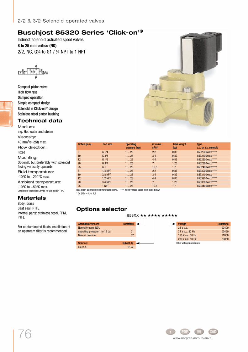
76 www.norgren.com/fc/en76
xxxx Insert solenoid codes from table below. ***** Insert voltage codes from table below
* Cv (US) Ÿ kv x 1,2
Other voltages on request
Buschjost 85320 Series ‘Click-on’®Indirect solenoid actuated spool valves8 to 25 mm orifice (ND)
2/2, NC, GÊ to G1 / Ê NPT to 1 NPT
Options selector 853XX ˙˙ ˙˙˙˙ ˙˙˙˙˙
8 G 1/4 1 ... 25 2,2 0,83 8532000xxxx*****10 G 3/8 1 ... 25 3,4 0,82 8532100xxxx*****12 G 1/2 1 ... 25 4,4 0,85 8532200xxxx*****20 G 3/4 1 ... 25 7 1,25 8532300xxxx*****25 G 1 1 ... 25 10,5 1,7 8532400xxxx*****8 1/4 NPT 1 ... 25 2,2 0,83 8533000xxxx*****10 3/8 NPT 1 ... 25 3,4 0,82 8533100xxxx*****12 1/2 NPT 1 ... 25 4,4 0,85 8533200xxxx*****20 3/4 NPT 1 ... 25 7 1,25 8533300xxxx*****25 1 NPT 1 ... 25 10,5 1,7 8533400xxxx*****
TTyyppeedd..cc.. oorr aa..cc.. ssoolleennooiidd
OOrriiffiiccee ((mmmm)) PPoorrtt ssiizzee OOppeerraattiinnggpprreessssuurree ((bbaarr))
kkvv vvaalluueemm33//hh**
TToottaall wweeiigghhtt((kkgg))
AAlltteerrnnaattiivvee vveerrssiioonnss SSuubbssttiittuutteeNormally open (NO),operating pressure 1 to 16 bar 01Manual override 02
SSoolleennooiidd SSuubbssttiittuutteed.c./a.c. 9152
VVoollttaaggee SSuubbssttiittuuttee24 V d.c. 0240024 V a.c. 50 Hz 02450110 V a.c. 50 Hz 11050230 V a.c. 50 Hz 23050
CCoommppaacctt ppiissttoonn vvaallvveeHHiigghh ffllooww rraatteeDDaammppeedd ooppeerraattiioonnSSiimmppllee ccoommppaacctt ddeessiiggnn
SSoolleennooiidd iinn CClliicckk--oonn® ddeessiiggnnSSttaaiinnlleessss sstteeeell ppiissttoonn bbuusshhiinngg
Technical dataMedium:e.g. Hot water and steamViscosity:40 mm2/s (cSt) max.Flow direction:FixedMounting:Optional, but preferably with solenoidfacing vertically upwards Fluid temperature:-10°C to +200°C max.Ambient temperature:-10°C to +50°C max.Consult our Technical Service for use below +2°C
MaterialsBody: brassSeat seal: PTFEInternal parts: stainless steel, FPM,PTFE
For contaminated fluids installation ofan upstream filter is recommended.
2/2 & 3/2 Solenoid operated valves

77
Buschjost 85320 Series ‘Click-on’®Indirect solenoid actuated spool valves
8 to 25 mm orifice (ND)2/2, NC, GÊ to G1 / Ê NPT to 1 NPT
Solenoid rotates 360°
Electrical details for solenoid operators
According to VDE 0580, 100% ratedPower consumption calculated with coil at +20°C, for d.c. coils at operating temperature, power consumption is up to 30% lower
Device socket can be turned through 4 x 90°(device socket supplied with product)
ØØ AA BB HH HH11 LL LL11 RR TT8532000xxxx***** 44 19,5 105 93,5 60 27,5 G 1/4 128533000xxxx***** 44 19,5 105 93,5 60 27,5 1/4 NPT 108532100xxxx***** 44 19,5 105 93,5 60 27,5 G 3/8 128533100xxxx***** 44 19,5 105 93,5 60 27,5 3/8 NPT 10,58532200xxxx***** 44 19,5 107,5 93,5 67 31 G 1/2 148533200xxxx***** 44 19,5 107,5 93,5 67 31 1/2 NPT 13,58532300xxxx***** 50 24 119 102,5 80 36,5 G 3/4 168533300xxxx***** 50 24 119 102,5 80 36,5 3/4 NPT 148532400xxxx***** 62 29,5 131,5 110,5 95 44 G 1 188533400xxxx***** 62 29,5 131,5 110,5 95 44 1 NPT 17
MMooddeell
10 15 VA/10 W 417 48 – IP 65 +200 max. -25 ... +60 DIN EN 175301-803 0,40 24 1 1 9152
# For solenoid dimensional drawingsand circuit diagrams, see page 97
MMooddeellPPoowweerr ccoonnssuummppttiioonn VVoollttaaggee2244 VV dd..cc..((WW))
223300 VV aa..cc..((VVAA))
CCaatteeggoorryy2244 VV dd..cc..((mmAA))
223300 VV aa..cc..((mmAA))
PPrrootteeccttiioonn ccllaassss TTeemmppeerraattuurreess °°CCFFlluuiidd** AAmmbbiieenntt****
EElleeccttrriiccaall ccoonnnneeccttiioonn kkgg CCiirrccuuiittddiiaaggrraamm##dd..cc.. aa..cc..
* The maximum temperature depends on the valve type** The maximum temperature may be higher, depending on the application.
Solenoiddrawingno.#

78 www.norgren.com/fc/en78
Buschjost 82730 / 82740 SeriesIndirect solenoid actuated diaphragm valves8 to 25 mm orifice (ND)2/2, NC, GÊ to G1 / Ê NPT to 1 NPT
Options selector 827XX ˙˙ ˙˙˙˙ ˙˙˙˙˙
VVoollttaaggee SSuubbssttiittuuttee24 V d.c. 0240024 V a.c. 50 Hz 02450110 V a.c. 50 Hz 11050230 V a.c. 50 Hz 23050
8 G 1/4 0,1 ... 16 1,90 0,47 8273000xxxx*****10 G 3/8 0,1 ... 16 3,00 0,45 8273100xxxx*****12 G 1/2 0,1 ... 16 3,80 0,50 8273200xxxx*****20 G 3/4 0,1 ... 16 6,10 0,65 8273300xxxx*****25 G 1 0,1 ... 16 9,50 0,95 8273400xxxx*****8 1/4 NPT 0,1 ... 16 1,90 0,47 8274000xxxx*****10 3/8 NPT 0,1 ... 16 3,00 0,45 8274100xxxx*****12 1/2 NPT 0,1 ... 16 3,80 0,50 8274200xxxx*****20 3/4 NPT 0,1 ... 16 6,10 0,65 8274300xxxx*****25 1 NPT 0,1 ... 16 9,50 0,95 8274400xxxx*****
Other voltages on request
* Only for alternative version 81
HHiigghh ffllooww rraatteeDDaammppeedd ooppeerraattiioonnSSiimmppllee ccoommppaacctt ddeessiiggnnSSoolleennooiidd iinntteerrcchhaannggeeaabbllee wwiitthhoouuttttoooollss ((CClliicckk--oonn®®))
Technical dataMedium:Semi-aggressive gases and liquidsViscosity:25 mm2/s (cSt) max.Flow direction:FixedMounting:Optional, but preferably with solenoidfacing vertically upwards Fluid temperature:-10°C to +90°C max.Ambient temperature:-10°C to +50°C max.Consult our Technical Service for use below +2°C
MaterialsBody: stainless steel 1.4408Seat seal: NBR (Perbunan)Internal parts: stainless steel, PVDF
For contaminated fluids installation ofan upstream filter is recommended.
MMooddeellOOrriiffiiccee((mmmm))
PPoorrtt ssiizzee OOppeerraattiinnggpprreessssuurree ((bbaarr))
kkvv vvaalluueemm33//hh**
TToottaall wweeiigghhtt((kkgg))
AAlltteerrnnaattiivvee vveerrssiioonnss SSuubbssttiittuutteeNormally open (NO) 01Seat seal material FPM,max. fluid temperature +110°C 03Seat seal material EPDM,for hot water, max. fluid temperature +110°C; 0,3 to 16 bar up to ND 25 mm 14Solenoid sleeve free of non-ferrous metals,seat seal material FPM, fluid temperature max. 110°C,with a.c. supply, solenoid with rectifier 81
SSoolleennooiidd SSuubbssttiittuutteed.c./a.c. 9101a.c.* 9104EEx m II T4 9136
* Cv (US) Ÿ kv x 1,2xxxx Insert solenoid codes from table below. ***** Insert voltage codes from table below
2/2 & 3/2 Solenoid operated valves

Electrical details for solenoid operators
79
Buschjost 82730 / 82740 SeriesIndirect solenoid actuated diaphragm valves
8 to 25 mm orifice (ND)2/2, NC, GÊ to G1 / Ê NPT to 1 NPT
ØØ AA BB HH HH11 LL LL11 RR TT
8273000xxxx***** 44 19,5 78,5 67,0 60 27,5 G 1/4 12,08274000xxxx***** 44 19,5 78,5 67,0 60 27,5 1/4 NPT 10,08273100xxxx***** 44 19,5 78,5 67,0 60 27,5 G 3/8 12,08274100xxxx***** 44 19,5 78,5 67,0 60 27,5 3/8 NPT 10,58273200xxxx***** 44 19,5 81,0 67,0 67 31,0 G 1/2 14,08274200xxxx***** 44 19,5 81,0 67,0 67 31,0 1/2 NPT 13,58273300xxxx***** 50 24,0 88,0 71,5 80 36,5 G 3/4 16,08274300xxxx***** 50 24,0 88,0 71,5 80 36,5 3/4 NPT 14,08273400xxxx***** 62 29,5 97,5 77,0 95 44,0 G 1 18,08274400xxxx***** 62 29,5 97,5 77,0 95 44,0 1 NPT 17,0
Solenoid rotates 360°
Device socket can be turned through 4 x 90°(device socket supplied with product)
MMooddeell
According to VDE 0580, 100% ratedPower consumption calculated with coil at +20°C, for d.c. coils at operating temperature, power consumption is up to 30% lowerCable clamping range 5 to 10 mm
Caution! For standard solenoid sleeve with copper ring, check fluid resistance.
8 15/12 333 52 – IP 65 +110 max. -25 ... +50 DIN EN 175301-803 0,15 17 1 1 91018 9 VA/8 W 333 39 – IP 65 +110 max. -25 ... +50 DIN EN 175301-803 0,25 17 – 6 9104
8 9 VA/8 W 333 39 II 2 GD EEx m II T4, IP67 +80 max. -20 ... +40 3 m cable 0,40 27 2 6 9136
# For solenoid dimensional drawingsand circuit diagrams, see page 97
MMooddeellPPoowweerr ccoonnssuummppttiioonn VVoollttaaggee2244 VV dd..cc..((WW))
223300 VV aa..cc..((VVAA))
CCaatteeggoorryy2244 VV dd..cc..((mmAA))
223300 VV aa..cc..((mmAA))
PPrrootteeccttiioonn ccllaassss TTeemmppeerraattuurreess °°CCFFlluuiidd** AAmmbbiieenntt****
EElleeccttrriiccaall ccoonnnneeccttiioonn kkgg CCiirrccuuiittddiiaaggrraamm##dd..cc.. aa..cc..
* The maximum temperature depends on the valve type** The maximum temperature may be higher, depending on the application.
Solenoiddrawingno.#

80 www.norgren.com/fc/en80
Buschjost 82540 / 82640 Series ‘Click-on’®Solenoid actuated diaphragm valves with forced lifting8 to 50 mm orifice (ND)2/2, NC, GÊ to G2, Ê NPT to 2 NPT
HHiigghh ffllooww rraatteeFFoorr rroobbuusstt iinndduussttrryy ssoolluuttiioonnssDDaammppeedd ooppeerraattiioonnSSuuiittaabbllee ffoorr vvaaccuuuummFFoorr ssyysstteemmss wwiitthh llooww oorr ddiissccoonnttiinnuuoouusspprreessssuurreeSSoolleennooiidd iinntteerrcchhaannggeeaabbllee wwiitthhoouutt ttoooollss((CClliicckk--oonn®®))VVaallvvee ooppeerraatteess wwiitthhoouutt ddiiffffeerreennttiiaallpprreessssuurree ((∂∂pp))
Technical dataMedium:Neutral gases and liquid fluidsViscosity:25 mm2/s max.(cSt)Flow direction:FixedMounting:Optional, but preferably with solenoidfacing vertically upwards Fluid temperature:-10°C to +90°C max.Ambient temperature:-10°C to +50°C max.Consult our Technical Service for use below +2°C
MaterialsBody: brassSeat seal: NBR (Perbunan)Internal parts: stainless steel, PVDF,brass
For contaminated fluids installation ofan upstream filter is recommended.
Options selector 8254X ˙˙ ˙˙˙˙ ˙˙˙˙˙
SSoolleennooiidd SSuubbssttiittuutteed.c. (G1/4 to G1, 1/4 to 1 NPT) 9151a.c. (G1/4 to G1, 1/4 to 1 NPT) 9154d.c. (G1Ê to G2, 1Ê to 2 NPT) 9401a.c. (G1Ê to G2, 1Ê to 2 NPT) 9404d.c. (G1/4 to G2, 1Ê to 2 NPT)* 8401a.c. (G1/4 to G2, 1Ê to 2 NPT)* 8404
VVoollttaaggee SSuubbssttiittuuttee24 V d.c. 0240024 V a.c. 40 to 60 Hz 0244942 V a.c. 40 to 60 Hz 04249110 V a.c. 40 to 60 Hz 11049230 V a.c. 40 to 60 Hz 23049
AAlltteerrnnaattiivvee vveerrssiioonnss SSuubbssttiittuutteeNormally open (NO) 01Seat seal material FPM,max. fluid temperature +110°C 03Seat seal material EPDM, for hot watermax. fluid temperature +110°C 14
xxxx Insert solenoid codes from table below. ***** Insert voltage codes from table below
* Cv (US) Ÿ kv x 1,2
8 G 1/4 0 ... 10 1,9 0,79 8254000xxxx*****10 G 3/8 0 ... 10 3,0 0,77 8254100xxxx*****12 G 1/2 0 ... 10 3,4 0,80 8254200xxxx*****20 G 3/4 0 ... 10 5,8 0,97 8254300xxxx*****25 G 1 0 ... 10 8,0 1,30 8254400xxxx*****32 G 1Ê 0 ... 10 23,0 4,30 8254500xxxx*****40 G 1Ë 0 ... 10 25,0 4,30 8254600xxxx*****50 G 2 0 ... 10 41,0 5,40 8254700xxxx*****8 1/4 NPT 0 ... 10 1,9 0,79 8264000xxxx*****10 3/8 NPT 0 ... 10 3,0 0,77 8264100xxxx*****12 1/2 NPT 0 ... 10 3,4 0,80 8264200xxxx*****20 3/4 NPT 0 ... 10 5,8 0,97 8264300xxxx*****25 1 NPT 0 ... 10 8,0 1,30 8264400xxxx*****32 1Ê NPT 0 ... 10 23,0 4,30 8264500xxxx*****40 1Ë NPT 0 ... 10 25,0 4,30 8264600xxxx*****50 2 NPT 0 ... 10 41,0 5,40 8264700xxxx*****
OOrriiffiiccee ((mmmm)) PPoorrtt ssiizzee OOppeerraattiinnggpprreessssuurree ((bbaarr))
kkvv vvaalluueemm33//hh**
TToottaall wweeiigghhtt((kkgg))
MMooddeell
a.c. version with built-in rectifier
* Only in combination with alternative version 01
2/2 & 3/2 Solenoid operated valves

81
Buschjost 82540 / 82640 Series ‘Click-on’®Solenoid actuated diaphragm valves with forced lifting
8 to 50 mm orifice (ND)2/2, NC, GÊ to G2, Ê NPT to 2 NPT
Electrical details for solenoid operators
According to VDE 0580, 100% ratedPower consumption calculated with coil at +20°C, for d.c. coils at operating temperature, power consumption is up to 30% lower
Device socket can be turned through 4 x 90°
Solenoid rotates 360°
ØØ AA HH HH11 LL LL11 RR TT
8254000 915x 44 104,0 92,5 60 27,5 G 1/4 12,08264000 915x 44 104,0 92,5 60 27,5 1/4 NPT 10,08254100 915x 44 104,0 92,5 60 27,5 G 3/8 12,08264100 915x 44 104,0 92,5 60 27,5 3/8 NPT 10,58254200 915x 44 108,0 94,5 67 31,0 G 1/2 14,08264200 915x 44 108,0 94,5 67 31,0 1/2 NPT 13,58254300 915x 50 115,0 99,0 80 36,5 G 3/4 16,08264300 915x 50 115,0 99,0 80 36,5 3/4 NPT 14,08254400 915x 62 124,0 103,5 95 44,0 G 1 18,08264400 915x 62 124,0 103,5 95 44,0 1 NPT 17,08254500 940x 92 186,0 157,0 132 60,0 G 1Ê 20,08264500 940x 92 186,0 157,0 132 60,0 1Ê NPT 17,08254600 940x 92 186,0 157,0 132 60,0 G 1Ë 22,08264600 940x 92 186,0 157,0 132 60,0 1Ë NPT 17,08254700 940x 109 201,5 167,0 160 74,0 G 2 24,08264700 940x 109 201,5 167,0 160 74,0 2 NPT 17,5
MMooddeell
18 45/35 750 152 – IP 65 +110 max -25 ... +50 DIN EN 175301-803 0,40 24 1 1 9151– 20 VA/18 W – 88 – IP 65 +110 max -25 ... +50 DIN EN 175301-803 0,40 24 – 6 9154
38 – 1583 – – IP 65 +110 max. -25 ... +50 DIN EN 175301-803 1,40 25 1 – 9401– 42 VA/38 W – 185 – IP 65 +110 max. -25 ... +50 DIN EN 175301-803 1,40 25 – 6 9404
40 – 1667 – – IP 65 +110 max. -25 ... +50 DIN EN 175301-803 1,70 18 1 – 8401– 45 VA/40 W – 195 – IP 65 +110 max. -25 ... +50 DIN EN 175301-803 1,70 18 – 6 8404
# For solenoid dimensional drawingsand circuit diagrams, see page 97
MMooddeellPPoowweerr ccoonnssuummppttiioonn VVoollttaaggee2244 VV dd..cc..((WW))
223300 VV aa..cc..((VVAA))
CCaatteeggoorryy2244 VV dd..cc..((mmAA))
223300 VV aa..cc..((mmAA))
PPrrootteeccttiioonn ccllaassss TTeemmppeerraattuurreess °°CCFFlluuiidd** AAmmbbiieenntt****
EElleeccttrriiccaall ccoonnnneeccttiioonn kkgg CCiirrccuuiittddiiaaggrraamm##dd..cc.. aa..cc..
* The maximum temperature depends on the valve type** The maximum temperature may be higher, depending on the application.
Solenoiddrawingno.#

82 www.norgren.com/fc/en82
Buschjost 82530 / 82630 SeriesSolenoid actuated diaphragm valves with forced lifting10 mm orifice (ND)2/2, NC, GÊ to GË, Ê NPT to Ë NPT
SSuuiittaabbllee ffoorr vvaaccuuuummCClleeaarr ddeessiiggnnCCoommppaacctt ssoolleennooiidd wwiitthh iinntteeggrraatteeddccoorree ttuubbeeVVaallvvee ooppeerraatteess wwiitthhoouutt pprreessssuurreeddiiffffeerreennttiiaall ((∂∂pp))OOppeerraattiinngg pprreessssuurree 00 ttoo 2200 bbaarrwwiitthh aa..cc.. aanndd NNBBRR sseeaall
Technical dataMedium:Neutral gases and liquid fluidsViscosity:25 mm2/s (cSt) max.Flow direction:FixedMounting:Optional, but preferably withsolenoid facing vertically upwards Fluid temperature:-10°C to +90°C max.Ambient temperature:-10°C to +50°C max.Consult our Technical Service for use below +2°C
MaterialsBody: brass, PA 66Seat seal: NBR (Perbunan)Internal parts: stainless steel1.4104/430F, 1.4303, PVDF
For contaminated fluids installationof an upstream filter isrecommended.
Options selector 825XX ˙˙ ˙˙˙˙ ˙˙˙˙˙
SSoolleennooiidd SSuubbssttiittuutteed.c./a.c. 8001EEx me II T3 8041
VVoollttaaggee SSuubbssttiittuuttee24 V d.c. 0240024 V a.c. 50 Hz 02450110 V a.c. 50 Hz 11050230 V a.c. 50 Hz 23050
AAlltteerrnnaattiivvee vveerrssiioonnss SSuubbssttiittuutteeSeat seal material FPM,preferably for fuels and oils,max. fluid temperature +110°C 03Seat seal material EPDM, for hot water, max. fluid temperature +110°C 14Seat seal material HNBR, for hot water and steam, operating pressure 0 to 6 bar, fluid temperature 0°C to max. +150°C 51
xxxx Insert solenoid codes from table below. ***** Insert voltage codes from table below
* Cv (US) Ÿ kv x 1,2
Other voltages on request
10 G 1/4 0 ... 10 1,50 0,50 8253000xxxx*****10 G 3/8 0 ... 10 1,70 0,50 8253100xxxx*****10 G 1/2 0 ... 10 1,70 0,60 8253200xxxx*****10 1/4 NPT 0 ... 10 1,50 0,50 8263000xxxx*****10 3/8 NPT 0 ... 10 1,70 0,50 8263100xxxx*****10 1/2 NPT 0 ... 10 1,70 0,60 8263200xxxx*****
MMooddeellOOrriiffiiccee ((mmmm)) PPoorrtt ssiizzee OOppeerraattiinnggpprreessssuurree ((bbaarr))
kkvv vvaalluueemm33//hh**
TToottaall wweeiigghhtt((kkgg))
2/2 & 3/2 Solenoid operated valves

83
Buschjost 82530 / 82630 SeriesSolenoid actuated diaphragm valves with forced lifting
10 mm orifice (ND)2/2, NC, GÊ to GË, Ê NPT to Ë NPT
Device socket can be turned through4 x 90°
8253000xxxx***** 44 85,5 73 12,5 21 G 1/4 128263000xxxx***** 44 85,5 73 12,5 21 1/4 NPT 108253100xxxx***** 44 85,5 73 12,5 21 G 3/8 128263100xxxx***** 44 85,5 73 12,5 21 3/8 NPT 108253200xxxx***** 60 88,5 74,5 14 27 G 1/2 158263200xxxx***** 60 88,5 74,5 14 27 1/2 NPT 13
LL HH HH11 BB SSWW RR TTMMooddeell
According to VDE 0580, 100% ratedPower consumption calculated with coil at +20°C, for d.c. coils at operating temperature, power consumption is up to 30% lower
Cable clamping range 5 to 10 mm
12/12 20/16 500 70 – IP 65 +110 max.. -25 ... +50 DIN EN 175301-803 0,22 16 1 1 8001
12 13 VA/12 W 500 59 II 2 GD EEx me II T3, IP65 +80 max. -20 ... +40 Connector body 0,30 23 2 6 8041
# For solenoid dimensional drawingsand circuit diagrams, see page 97
MMooddeellPPoowweerr ccoonnssuummppttiioonn VVoollttaaggee2244 VV dd..cc..((WW))
223300 VV aa..cc..((VVAA))
CCaatteeggoorryy2244 VV dd..cc..((mmAA))
223300 VV aa..cc..((mmAA))
PPrrootteeccttiioonn ccllaassss TTeemmppeerraattuurreess °°CCFFlluuiidd** AAmmbbiieenntt****
EElleeccttrriiccaall ccoonnnneeccttiioonn kkgg CCiirrccuuiittddiiaaggrraamm##dd..cc.. aa..cc..
* The maximum temperature depends on the valve type** The maximum temperature may be higher, depending on the application.
Electrical details for solenoid operatorsSolenoiddrawingno.#

84 www.norgren.com/fc/en84
* Up to +200°C fluid temperature with high-temperature solenoid** G 3/8 (3/8 NPT) and G 1/2 (1/2 NPT) with solenoid 8401/8404
Buschjost 85040 / 85050 SeriesSolenoid actuated angle seat valves with forced lifting10 to 25 mm orifice (ND)2/2, NC, GÁ to G1 / Á NPT to 1 NPT
FFllaatt ppiissttoonn vvaallvveeVVaallvvee ooppeerraatteess wwiitthhoouutt pprreessssuurreeddiiffffeerreennttiiaall ((∂∂pp))HHiigghh ffllooww rraatteeDDaammppeedd ooppeerraattiioonnSSuuiittaabbllee ffoorr vvaaccuuuumm
Technical dataMedium:Semi-aggressive gases and liquidsViscosity:40 mm2/s (cSt) max.Flow direction:FixedMounting:Optional, but preferably withsolenoid facing vertically upwards Fluid temperature:-20°C to +90°C max.Ambient temperature:-20°C to +50°C max.Consult our Technical Service for use below +2°C
MaterialsBody: stainless steel Seat seal: NBR (flexible when cold)Internal parts: stainless steel,Sandvik 1802
For contaminated fluids installationof an upstream filter isrecommended.
Options selector 850XX ˙˙ ˙˙˙˙ ˙˙˙˙˙
SSoolleennooiidd SSuubbssttiittuutteed.c. (G3/8 to G1/2, 3/8 to 1/2 NPT) 8301a.c. (G3/8 to G1/2, 3/8 to 1/2 NPT) 8304d.c. (G3/4 to G1, 3/4 to 1 NPT) 8401a.c. (G3/4 to G1, 3/4 to 1 NPT) 8404EEx me II T3 (G3/8 to G1/2, 3/8 to 1/2 NPT) 8341EEx me II T3 (G3/4 to G1, 3/4 to 1 NPT) 8441EEx de IIC T4/T5 (G3/4 to G1, 3/4 to 1 NPT) 8900EEx d IIC T4/T5 (G3/4 to G1, 3/4 to 1 NPT) 8920
VVoollttaaggee SSuubbssttiittuuttee24 V d.c. 0240024 V a.c. 40 to 60 Hz 02449110 V a.c. 40 to 60 Hz 11049230 V a.c. 40 to 60 Hz 23049
AAlltteerrnnaattiivvee vveerrssiioonnss SSuubbssttiittuutteeNormally open,mounting position: Solenoid vertically upwards** 01Seat and soft seal material FPM,max. fluid temperature +110°C* 03Seat and soft seal material PTFE,max. fluid temperature +110°C, max. operating pressure 16 bar* 06Seat and soft seal material EPDM, max. fluid temperature +110°C 14Max. operating pressure 40 bar** 22Position indicator with 2 magnetic switches ** 23
xxxx Insert solenoid codes from table below. ***** Insert voltage codes from table below
* Cv (US) Ÿ kv x 1,2
10 G 3/8 0 ... 25 3,4 1,50 8504100xxxx*****12 G 1/2 0 ... 25 3,8 1,45 8504200xxxx*****20 G 3/4 0 ... 25 11,0 3,65 8504300xxxx*****25 G 1 0 ... 25 13,0 3,50 8504400xxxx *****10 3/8 NPT 0 ... 25 3,4 1,50 8505100xxxx*****12 1/2 NPT 0 ... 25 3,8 1,45 8505200xxxx*****20 3/4 NPT 0 ... 25 11,0 3,65 8505300xxxx*****25 1 NPT 0 ... 25 13,0 3,50 8505400xxxx*****
a.c. version with built-in rectifier
MMooddeellOOrriiffiiccee ((mmmm)) PPoorrtt ssiizzee OOppeerraattiinnggpprreessssuurree ((bbaarr))
kv valuem3/h**
TToottaall wweeiigghhtt((kkgg))
2/2 & 3/2 Solenoid operated valves

85
Buschjost 85040 / 85050 SeriesSolenoid actuated angle seat valves with forced lifting
10 to 25 mm orifice (ND)2/2, NC, GÁ to G1 / Á NPT to 1 NPT
Electrical details for solenoid operators
According to VDE 0580, 100% ratedPower consumption calculated with coil at +20°C, for d.c. coils at operating temperature, power consumption is up to 30% lower
Cable clamping range 5 to 10 mmNote: Restricted temperature range with explosion-proof solenoids
Device socket can be turned through 4 x 90°
Solenoid rotates 360°
8504100 830x 52 x 65 65 45 26 165 150 67 G 3/8 128505100 830x 52 x 65 65 45 26 165 150 67 3/8 NPT 10,58504200 830x 52 x 65 65 45 26 165 150 67 G 1/2 128505200 830x 52 x 65 65 45 26 165 150 67 1/2 NPT 138504300 840x 72 x 92 75 70 31 196 172 95 G 3/4 12,58505300 840x 72 x 92 75 70 31 196 172 95 3/4 NPT 148504400 840x 72 x 92 75 70 31 196 172 95 G 1 148505400 840x 72 x 92 75 70 31 196 172 95 1 NPT 17
AA xx BB CC …… CC EE HH HH11 LL RR TTMMooddeell
22 – 917 – – IP 65 +110 max. -25 ... +50 DIN EN 175301-803 0,70 30 1 – 8301– 25 VA/22 W – 107 – IP 65 +110 max. -25 ... +50 DIN EN 175301-803 0,70 30 – 6 8304
40 – 1667 – – IP 65 +110 max. -25 ... +50 DIN EN 175301-803 1,70 18 1 – 8401– 45 VA/40 W – 195 – IP 65 +110 max. -25 ... +50 DIN EN 175301-803 1,70 18 – 6 8404
22 25 VA/22 W 917 107 II 2 GD EEx me II T3, IP65 +80 max, -20 ... +40 Connector body 0,85 28 2 6 8341
29 33 VA/29 W 1208 141 II 2 GD EEx de IIC T4/T5, IP65 +110 max. -40 ... +60/40 Cable fitting 6,30 29 2 6 890029 33 VA/29 W 1208 141 II 2 GD EEx d IIC T4/T5, IP65 +100 max. -40 ... +75/40 Cable fitting 6,30 29 2 6 8920
# For solenoid dimensionaldrawings and circuit diagrams, seepage 97 & 98
40 45 VA/40 W 1667 195 II 2 GD EEx me II T3, IP65 +80 max. -20 ... +40 Connector body 1,80 19 2 6 8441
MMooddeellPPoowweerr ccoonnssuummppttiioonn VVoollttaaggee2244 VV dd..cc..((WW))
223300 VV aa..cc..((VVAA))
CCaatteeggoorryy2244 VV dd..cc..((mmAA))
223300 VV aa..cc..((mmAA))
PPrrootteeccttiioonn ccllaassss TTeemmppeerraattuurreess °°CCFFlluuiidd** AAmmbbiieenntt****
EElleeccttrriiccaall ccoonnnneeccttiioonn kkgg CCiirrccuuiittddiiaaggrraamm##dd..cc.. aa..cc..
* The maximum temperature depends on the valve type** The maximum temperature may be higher, depending on the application.
Solenoiddrawingno.#

86 www.norgren.com/fc/en86
Buschjost 85140 / 84140 SeriesSolenoid actuated angle seat valves with forced lifting15 to 100 mm orifice (ND)2/2, NC, flange connection PN 16
VVaallvvee ooppeerraatteess wwiitthhoouutt pprreessssuurreeddiiffffeerreennttiiaall ((∂∂pp))HHiigghh ffllooww rraatteeDDaammppeedd ooppeerraattiioonn
Technical dataMedium:Semi-aggressive gases and liquidsViscosity:40 mm2/s (cSt) max.Flow direction:FixedMounting:Optional, but preferably with solenoidfacing vertically upwards; from ND65 mm, only with solenoid facingvertically upwardsFluid temperature:-20°C to +110°C (15 to 50 mm orifice)-10°C to +110°C (65 to 100 mm orifice)Ambient temperature:+50°C max.Consult our Technical Service for use below +2°C
Sum of fluid and ambienttemperatures:+130°C max.
MaterialsBody: stainless steel 1.4581/316TISeat seal: PTFE (Teflon)Internal parts: 1.4571/316T, 1.4301,1.4310; Sandvik 1802 up to 50 mm;1.4104/430F and 1.4105 from 65 mm
For contaminated fluids installation ofan upstream filter is recommended.
Options selector 851XX ˙˙ ˙˙˙˙ ˙˙˙˙˙
SSoolleennooiidd SSuubbssttiittuutteed.c. (ND 15) 8301a.c. (ND 15) 8304d.c. (ND 20 to 50) 8401a.c. (ND 20 to 50) 8404EEx me II T3 (ND 15) 8341EEx me II T3 (ND 20 to 50) 8441d.c. (ND 65 to 100) 9501a.c. (ND 65 to 100) 9504EEx me II T3/T4 (ND 65 to 100) 9540
VVoollttaaggee SSuubbssttiittuuttee24 V d.c. 0240024 V 40 to 60 Hz 02449110 V 40 to 60 Hz 11049230 V 40 to 60 Hz 23049
AAlltteerrnnaattiivvee vveerrssiioonnss SSuubbssttiittuutteeNormally open,installation position: solenoid vertically upwards* 01Position indicator with2 magnetic switches* 23
xxxx Insert solenoid codes from table below. ***** Insert voltage codes from table below* Cv (US) Ÿ kv x 1,2
15 PN 16 0 ... 16 5,5 5,5 8514200xxxx*****20 PN 16 0 ... 16 10,0 5,8 8514300xxxx*****25 PN 16 0 ... 16 12,5 6,2 8514400xxxx*****32 PN 16 0 ... 16 27,0 11,0 8514500xxxx*****40 PN 16 0 ... 16 31,0 11,8 8514600xxxx*****50 PN 16 0 ... 16 43,0 14,0 8514700xxxx*****65 PN 16 0 ... 16 67,0 36,5 8414800xxxx*****80 PN 16 0 ... 16 94,0 46,5 8414900xxxx*****100 PN 16 0 ... 16 144,0 70,0 8415000xxxx*****
* ND 15 mm with solenoid 8401/8404 a.c. version with built-in rectifier
OOrriiffiiccee ((mmmm)) PPoorrtt ssiizzee OOppeerraattiinnggpprreessssuurree ((bbaarr))
kkvv vvaalluueemm33//hh**
TToottaall wweeiigghhtt((kkgg))
MMooddeell
2/2 & 3/2 Solenoid operated valves

87
22 – 917 – – IP 65 +110 max. -25 ... +50 DIN EN 175301-803 0,70 30 1 – 8301– 25 VA/22 W – 107 – IP 65 +110 max. -25 ... +50 DIN EN 175301-803 0,70 30 – 6 8304
40 – 1667 – – IP 65 +110 max. -25 ... +50 DIN EN 175301-803 1,70 18 1 – 8401– 45 VA/40 W – 195 – IP 65 +110 max. -25 ... +50 DIN EN 175301-803 1,70 18 – 6 8404
22 25 VA/22 W 917 107 II 2 GD EEx me II T3, IP65 +80 max, -20 ... +40 Connector body 0,85 28 2 6 8341
80 – 3333 – – IP 65 +110 max. -25 ... +50 DIN EN 175301-803 5,85 20 1 – 9501– 89 VA/80 W – 390 – IP 65 +110 max. -25 ... +50 DIN EN 175301-803 5,85 20 – 6 9504
Buschjost 85140 / 84140 SeriesSolenoid actuated angle seat valves with forced lifting
15 to 100 mm orifice (ND)2/2, NC, flange connection PN 16
Electrical details for solenoid operators
Device socket can be turned through4 x 90°
Solenoid rotates 360° Solenoid rotates 360°
8514200xxxx 52 x 65 65 70 26 145 130 15 958514300xxxx 72 x 92 75 70 31 172 150 20 1058514400xxxx 72 x 92 75 70 31 172 160 25 1158514500xxxx 72 x 92 75 96 31 187 180 32 1408514600xxxx 72 x 92 75 96 31 191 200 40 1508514700xxxx 72 x 92 75 112 31 200 230 50 165
Flange connection PN 16 according to DIN 2543/2545Sealing strip DIN 2526 Pattern C
Flange connection PN 16 according to DIN 2543Sealing strip DIN 2526 Pattern C
8414800xxxx 195 330 290 65 1858414900xxxx 220 350 310 80 2008415000xxxx 260 378 350 100 220
AA xx BB CC …… DD EE HH II DDNN ØØ FF ØØ AA HH II DDNN ØØ FFMMooddeell MMooddeell
According to VDE 0580, 100% ratedPower consumption calculated with coil at +20°C, for d.c. coils at operating temperature, power consumption is up to 30% lowerCable clamping range 5 to 10 mmNote: Restricted temperature range with explosion-proof solenoids
# For solenoid dimensionaldrawings and circuit diagrams,see page 97 & 98
40 45 VA/40 W 1667 195 II 2 GD EEx me II T3, IP65 +80 max. -20 ... +40 Connector body 1,80 19 2 6 8441
65 72 VA/65 W 2708 317 II 2 GD EEx me II T3/T4, IP65 +70/100 max -20 ...+40 Cable fitting 7,30 21 2 6 9540
MMooddeellPPoowweerr ccoonnssuummppttiioonn VVoollttaaggee2244 VV dd..cc..((WW))
223300 VV aa..cc..((VVAA))
CCaatteeggoorryy2244 VV dd..cc..((mmAA))
223300 VV aa..cc..((mmAA))
PPrrootteeccttiioonn ccllaassss TTeemmppeerraattuurreess °°CCFFlluuiidd** AAmmbbiieenntt****
EElleeccttrriiccaallccoonnnneeccttiioonn
kkgg CCiirrccuuiittddiiaaggrraamm##dd..cc.. aa..cc..
* The maximum temperature depends on the valve type** The maximum temperature may be higher, depending on the application.
Solenoiddrawing no.#
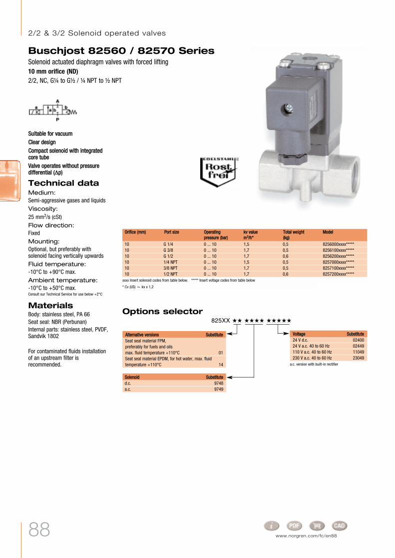
88 www.norgren.com/fc/en88
SSuuiittaabbllee ffoorr vvaaccuuuummCClleeaarr ddeessiiggnnCCoommppaacctt ssoolleennooiidd wwiitthh iinntteeggrraatteeddccoorree ttuubbeeVVaallvvee ooppeerraatteess wwiitthhoouutt pprreessssuurreeddiiffffeerreennttiiaall ((∂∂pp))
Technical dataMedium:Semi-aggressive gases and liquidsViscosity:25 mm2/s (cSt)Flow direction:FixedMounting:Optional, but preferably withsolenoid facing vertically upwards Fluid temperature:-10°C to +90°C max.Ambient temperature:-10°C to +50°C max.Consult our Technical Service for use below +2°C
MaterialsBody: stainless steel, PA 66Seat seal: NBR (Perbunan)Internal parts: stainless steel, PVDF,Sandvik 1802
For contaminated fluids installationof an upstream filter isrecommended.
Options selector 825XX ˙˙ ˙˙˙˙ ˙˙˙˙˙
SSoolleennooiidd SSuubbssttiittuutteed.c. 9748a.c. 9749
VVoollttaaggee SSuubbssttiittuuttee24 V d.c. 0240024 V a.c. 40 to 60 Hz 02449110 V a.c. 40 to 60 Hz 11049230 V a.c. 40 to 60 Hz 23049
AAlltteerrnnaattiivvee vveerrssiioonnss SSuubbssttiittuutteeSeat seal material FPM,preferably for fuels and oilsmax. fluid temperature +110°C 01Seat seal material EPDM, for hot water, max. fluidtemperature +110°C 14
xxxx Insert solenoid codes from table below. ***** Insert voltage codes from table below
* Cv (US) Ÿ kv x 1,2
10 G 1/4 0 ... 10 1,5 0,5 8256000xxxx*****10 G 3/8 0 ... 10 1,7 0,5 8256100xxxx*****10 G 1/2 0 ... 10 1,7 0,6 8256200xxxx*****10 1/4 NPT 0 ... 10 1,5 0,5 8257000xxxx*****10 3/8 NPT 0 ... 10 1,7 0,5 8257100xxxx*****10 1/2 NPT 0 ... 10 1,7 0,6 8257200xxxx*****
a.c. version with built-in rectifier
OOrriiffiiccee ((mmmm)) PPoorrtt ssiizzee OOppeerraattiinnggpprreessssuurree ((bbaarr))
kkvv vvaalluueemm33//hh**
TToottaall wweeiigghhtt((kkgg))
MMooddeell
Buschjost 82560 / 82570 SeriesSolenoid actuated diaphragm valves with forced lifting10 mm orifice (ND)2/2, NC, GÊ to GË / Ê NPT to Ë NPT
2/2 & 3/2 Solenoid operated valves

89
Electrical details for solenoid operators
Solenoid and device socket can beturned through 4 x 90°
8256000 974X 44 85,5 73,0 12,5 21 G 1/4 12,08257000 974X 44 85,5 73,0 12,5 21 1/4 NPT 10,08256100 974X 44 85,5 73,0 12,5 21 G 3/8 12,08257100 974X 44 85,5 73,0 12,5 21 3/8 NPT 10,08256200 974X 60 88,5 74,5 14,0 27 G 1/2 15,08257200 974X 60 88,5 74,5 14,0 27 1/2 NPT 13,0
LL HH HH11 BB SSWW RR TT
Buschjost 82560 / 82570 SeriesSolenoid actuated diaphragm valves with forced lifting
10 mm orifice (ND)2/2, NC, GÊ to GË / Ê NPT to Ë NPT
MMooddeell
According to VDE 0580, 100% ratedPower consumption calculated with coil at +20°C, for d.c. coils at operating temperature, power consumption is up to 30% lower
12 – 500 – – IP 65 +110 max. -25 ... +50 DIN EN 175301-803 0,22 16 1 – 9748– 13 VA/12 W – 59 – IP 65 +110 max. -25 ... +50 DIN EN 175301-803 0,22 16 – 6 9749
# For solenoid dimensional drawingsand circuit diagrams, see page 97
MMooddeellPPoowweerr ccoonnssuummppttiioonn VVoollttaaggee2244 VV dd..cc..((WW))
223300 VV aa..cc..((VVAA))
CCaatteeggoorryy2244 VV dd..cc..((mmAA))
223300 VV aa..cc..((mmAA))
PPrrootteeccttiioonnccllaassss
TTeemmppeerraattuurreess °°CCFFlluuiidd** AAmmbbiieenntt****
EElleeccttrriiccaall ccoonnnneeccttiioonn kkgg CCiirrccuuiittddiiaaggrraamm##dd..cc.. aa..cc..
* The maximum temperature depends on the valve type** The maximum temperature may be higher, depending on the application.
Solenoiddrawingno.#

90 www.norgren.com/fc/en90
Buschjost 82360 / 82460 SeriesSolenoid actuated diaphragm valves with forced liftting8 to 25 mm orifice (ND)2/2, NC, GÊ to G1 / Ê NPT to 1 NPT
VVaallvvee ooppeerraatteess wwiitthhoouutt pprreessssuurreeddiiffffeerreennttiiaall ((∂∂pp))HHiigghh ffllooww rraatteeEEaassiillyy iinntteerrcchhaannggeeaabbllee ssoolleennooiidd
Technical dataMedium:Neutral gases and liquid fluidsViscosity:25 mm2/s (cSt) max.Flow direction:FixedMounting:Optional, but preferably withsolenoid facing vertically upwards Fluid temperature:-10°C to +150°C max.Ambient temperature:-10°C to +60°C max.Consult our Technical Service for use below +2°C
MaterialsBody: brass Seat seal: HNBRInternal parts: stainless steel, brass,PVDF
For contaminated fluids installationof an upstream filter isrecommended.
Options selector 8236X ˙˙ ˙˙˙˙ ˙˙˙˙˙
SSoolleennooiidd SSuubbssttiittuutteed.c. 8302a.c. 8306
VVoollttaaggee SSuubbssttiittuuttee24 V d.c. 02400110 V d.c. 1100024 V a.c. 40 to 60 Hz 02449110 V a.c. 40 to 60 Hz 11049230 V a.c. 40 to 60 Hz 23049
AAlltteerrnnaattiivvee vveerrssiioonnssOn request
xxxx Insert solenoid codes from table below. ***** Insert voltage codes from table below* Cv (US) Ÿ kv x 1,2
8 G 1/4 0 ... 10 1,90 1,3 8236000xxxx*****10 G 3/8 0 ... 10 2,60 1,2 8236100xxxx*****12 G 1/2 0 ... 10 3,20 1,2 8236200xxxx*****20 G 3/4 0 ... 10 7,00 1,9 8236300xxxx*****25 G 1 0 ... 10 8,00 1,8 8236400xxxx*****8 1/4 NPT 0 ... 10 1,90 1,3 8246000xxxx*****10 3/8 NPT 0 ... 10 2,60 1,2 8246100xxxx*****12 1/2 NPT 0 ... 10 3,20 1,2 8246200xxxx*****20 3/4 NPT 0 ... 10 7,00 1,9 8246300xxxx*****25 1 NPT 0 ... 10 8,00 1,8 8246400xxxx*****
a.c. version with built-in rectifier
OOrriiffiiccee ((mmmm)) PPoorrtt ssiizzee OOppeerraattiinnggpprreessssuurree ((bbaarr))
kkvv vvaalluueemm33//hh**
TToottaall wweeiigghhtt((kkgg))
MMooddeell
2/2 & 3/2 Solenoid operated valves

91
Buschjost 82360 / 82460 SeriesSolenoid actuated diaphragm valves with forced liftting
8 to 25 mm orifice (ND)2/2, NC, GÊ to G1 / Ê NPT to 1 NPT
Electrical details for solenoid operators
According to VDE 0580, 100% ratedPower consumption calculated with coil at +20°C, for d.c. coils at operating temperature, power consumption is up to 30% lower
Device socket can be turnedthrough 4 x 90°
Solenoid rotates 360°
8236000 830X 44 125 110 67 G 1/4 12,08246000 830X 44 125 110 67 1/4 NPT 10,08236100 830X 44 125 110 67 G 3/8 12,08246100 830X 44 125 110 67 3/8 NPT 10,58236200 830X 44 125 110 67 G 1/2 14,08246200 830X 44 125 110 67 1/2 NPT 13,58236300 830X 70 150 125 95 G 3/4 12,58246300 830X 70 150 125 95 3/4 NPT 14,08236400 830X 70 150 125 95 G 1 14,08246400 830X 70 150 125 95 1 NPT 17,0
…… AA HH HH11 LL RR TTMMooddeell
14 – 583 – – IP 65 +200 max. -25 ... +60 DIN EN 175301-803 0,70 30 1 – 8302– 16 VA/14 W – 68 – IP 65 +200 max. -25 ... +60 DIN EN 175301-803 0,70 30 – 6 8306
# For solenoid dimensional drawingsand circuit diagrams, see page 98
MMooddeellPPoowweerr ccoonnssuummppttiioonn VVoollttaaggee2244 VV dd..cc..((WW))
223300 VV aa..cc..((VVAA))
CCaatteeggoorryy2244 VV dd..cc..((mmAA))
223300 VV aa..cc..((mmAA))
PPrrootteeccttiioonnccllaassss
TTeemmppeerraattuurreess °°CCFFlluuiidd** AAmmbbiieenntt****
EElleeccttrriiccaall ccoonnnneeccttiioonn kkgg CCiirrccuuiittddiiaaggrraamm##dd..cc.. aa..cc..
* The maximum temperature depends on the valve type** The maximum temperature may be higher, depending on the application.
Solenoiddrawingno.#

92 www.norgren.com/fc/en92
HHiigghh ffllooww rraatteeFFoorr rroobbuusstt iinndduussttrryy ssoolluuttiioonnssDDaammppeedd ooppeerraattiioonnSSuuiittaabbllee ffoorr vvaaccuuuummFFoorr ssyysstteemmss wwiitthh llooww oorrddiissccoonnttiinnuuoouuss pprreessssuurreeVVaallvvee ooppeerraatteess wwiitthhoouutt pprreessssuurreeddiiffffeerreennttiiaallSSttaaiinnlleessss sstteeeell ppiissttoonnSSoolleennooiidd iinntteerrcchhaannggeeaabbllee wwiitthhoouuttttoooollss ((CClliicckk--oonn®®)) ttoo GG11
Technical dataMedium:Neutral gases and liquid fluidsViscosity:With gases and liquids up to40 mm2/s (cSt)Flow direction:FixedMounting:Optional, but preferably withsolenoid facing vertically upwardsFluid temperature:-10°C to max. +90°CAmbient temperature:-10°C to max. +50°CConsult our Technical Service for use below +2°C
MaterialsBody: brassSeat seal: NBR (Perbunan)Internal parts: stainless steels,PTFE/carbon
For contaminated fluids installationof an upstream filter isrecommended.
Options selector 857XX ˙˙ ˙˙˙˙ ˙˙˙˙˙
SSoolleennooiidd SSuubbssttiittuutteed.c. (ND 8 to 25) 9402a.c. (ND 8 to 25) 9406d.c. (ND 32 to 50) 8402a.c. (ND 32 to 50) 8406
VVoollttaaggee SSuubbssttiittuuttee24 V d.c. 02400205 V d.c. 2055024 V a.c. 40 to 60 Hz 02449110 V a.c. 40 to 60 Hz 11049230 V a.c. 40 to 60 Hz 23049
AAlltteerrnnaattiivvee vveerrssiioonnss SSuubbssttiittuutteeNormally open, installation position: solenoid verticallyupwards: only for solenoid 8400 01Manual override 02Seat seal material FPM,max. fluid temperature +110°C* 03Seat seal material PTFE, max. fluid temperature+110°C*, max. operating pressure 16 bar 06Seat seal material EPDM,max. fluid temperature +110°C 14Normally open, seat seal material FPM, max. fluidtemperature +110°C*, installation position:Solenoid vertically upwards, only with solenoid 8400 17Max. operating pressure 40 bar 22Position indicator with 2 magnetic switches;only with solenoid 8400 23Seat seal material FPM, with larger mounting holesin piston, e.g. for fuels and oils,max. viscosity 80 mm2/s (cSt)max. fluid temperature +110°C* 25Low-temperature version; down to -20°C 28
xxxx Insert solenoid codes from table below. ***** Insert voltage codes from table below
* Cv (US) Ÿ kv x 1,2
8 G 1/4 0 ... 25 2,2 2,40 8570000xxxx*****10 G 3/8 0 ... 25 3,4 2,40 8570100xxxx*****12 G 1/2 0 ... 25 4,4 2,50 8570200xxxx*****20 G 3/4 0 ... 25 7,0 2,70 8570300xxxx*****25 G 1 0 ... 25 10,5 3,10 8570400xxxx*****32 G 1Ê 0 ... 25 25,0 5,60 8570500xxxx*****40 G 1Ë 0 ... 25 27,0 5,40 8570600xxxx*****50 G 2 0 ... 25 43,0 6,80 8570700xxxx*****8 1/4 NPT 0 ... 25 2,2 2,40 8571000xxxx*****10 3/8 NPT 0 ... 25 3,4 2,40 8571100xxxx*****12 1/2 NPT 0 ... 25 4,4 2,50 8571200xxxx*****20 3/4 NPT 0 ... 25 7,0 2,70 8571300xxxx*****25 1 NPT 0 ... 25 10,5 3,10 8571400xxxx*****32 1Ê NPT 0 ... 25 25,0 5,60 8571500xxxx*****40 1Ë NPT 0 ... 25 27,0 5,40 8571600xxxx*****50 2 NPT 0 ... 25 43,0 6,80 8571700xxxx*****
OOrriiffiiccee ((mmmm)) PPoorrtt ssiizzee OOppeerraattiinnggpprreessssuurree ((bbaarr))
kkvv vvaalluueemm33//hh**
TToottaall wweeiigghhtt((kkgg))
MMooddeell
a.c. version with built-in rectifier
Buschjost 85700 / 85710 SeriesSolenoid actuated, with forced lifting8 to 50 mm orifice (ND)2/2, NC, GÊ to GË / Ê NPT to 2 NPT
* Up to +200°C fluid temperature with high-temperature solenoid
EEx solenoids, categories 2 and 3, on request
2/2 & 3/2 Solenoid operated valves

93
Buschjost 85700 / 85710 SeriesSolenoid actuated, with forced lifting
8 to 50 mm orifice (ND)2/2, NC, GÊ to GË / Ê NPT to 2 NPT
Electrical details for solenoid operators
According to VDE 0580, 100% ratedPower consumption calculated with coil at +20°C, for d.c. coils at operating temperature, power consumption is up to 30% lowerNote: Restricted temperature range with explosion-proof solenoids
Up to G 1 or 1 NPT From G 1Ê or 1Ê NPT
8570000.940x 44 152,0 140,5 60 27,5 G 1/4 12,08571000.940x 44 152,0 140,5 60 27,5 1/4 NPT 12,08570100.940x 44 152,0 140,5 60 27,5 G 3/8 12,08571100.940x 44 152,0 140,5 60 27,5 3/8 NPT 12,08570200.940x 44 154,5 140,5 67 31,0 G 1/2 14,08571200.940x 44 154,5 140,5 67 31,0 1/2 NPT 14,08570300.940x 50 162,0 146,5 80 36,5 G 3/4 16,08571300.940x 50 162,0 146,5 80 36,5 3/4 NPT 16,08570400.940x 62 183,0 162,0 95 44,0 G 1 18,08571400.940x 62 183,0 162,0 95 44,0 1 NPT 18,08570500.840x 92 212,5 183,5 132 60,0 G 1Ê 20,08571500.840x 92 212,5 183,5 132 60,0 1Ê NPT 20,08570600.840x 92 212,5 183,5 132 60,0 G 1Ë 22,08571600.840x 92 212,5 183,5 132 60,0 1Ë NPT 22,08570700.840x 109 226,5 192,0 160 74,0 G 2 24,08571700.840x 109 226,5 192,0 160 74,0 2 NPT 24,0
ØØ AA HH HH11 LL LL11 RR TTMMooddeell
Socket can be turned through 4 x 90°
Solenoid rotates 360°
Socket can be turned through 4 x 90°
Solenoid rotates 360°
38 – 1583 – – IP 65 +110 max. -25 ... +50 DIN EN 175301-803 1,40 25 1 – 9401– 42 VA/38 W – 185 – IP 65 +110 max. -25 ... +50 DIN EN 175301-803 1,40 25 – 6 9404
40 – 1667 – – IP 65 +110 max. -25 ... +50 DIN EN 175301-803 1,70 18 1 – 8401– 45 VA/40 W – 195 – IP 65 +110 max. -25 ... +50 DIN EN 175301-803 1,70 18 – 6 8404
# For solenoid dimensional drawingsand circuit diagrams, see page 97
MMooddeellPPoowweerr ccoonnssuummppttiioonn VVoollttaaggee2244 VV dd..cc..((WW))
223300 VV aa..cc..((VVAA))
CCaatteeggoorryy2244 VV dd..cc..((mmAA))
223300 VV aa..cc..((mmAA))
PPrrootteeccttiioonnccllaassss
TTeemmppeerraattuurreess °°CCFFlluuiidd** AAmmbbiieenntt****
EElleeccttrriiccaall ccoonnnneeccttiioonn kkgg CCiirrccuuiittddiiaaggrraamm##dd..cc.. aa..cc..
* The maximum temperature depends on the valve type** The maximum temperature may be higher, depending on the application.
Solenoiddrawingno.#

94 www.norgren.com/fc/en94
HHiigghh ffllooww rraatteeFFoorr rroobbuusstt iinndduussttrryy ssoolluuttiioonnssDDaammppeedd ooppeerraattiioonnVVaallvvee ooppeerraatteess wwiitthhoouutt pprreessssuurreeddiiffffeerreennttiiaallSSoolleennooiidd iinntteerrcchhaannggeeaabbllee wwiitthhoouuttttoooollss ((CClliicckk--oonn®)) ttoo GG11
Technical dataMedium:Neutral gases and liquidsViscosity:With gases and liquids up to40 mm2/s (cSt)Flow direction:FixedMounting:Solenoid facing verticallydownwards (up to +150°Cpreferably with solenoid facingvertically upwards)Fluid temperature:0°C to max. +200°CAmbient temperature:0°C to max. +60°CConsult our Technical Service for use below +2°C
MaterialsBody: brassSeat seal: PTFEInternal parts: stainless steels,PTFE/carbon/FPM
For contaminated fluids installationof an upstream filter isrecommended.
Options selector 857XX ˙˙ ˙˙˙˙ ˙˙˙˙˙
SSoolleennooiidd SSuubbssttiittuutteed.c. (ND 8 to 25) 9402a.c. (ND 8 to 25) 9406d.c. (ND 32 to 50) 8402a.c. (ND 32 to 50) 8406
AAlltteerrnnaattiivvee vveerrssiioonnssOn request
xxxx Insert solenoid codes from table below. ***** Insert voltage codes from table below* Cv (US) Ÿ kv x 1,2
8 G 1/4 0 ... 16 1,9 2,40 8572000xxxx*****10 G 3/8 0 ... 16 3,0 2,40 8572100xxxx*****12 G 1/2 0 ... 16 3,8 2,50 8572200xxxx*****20 G 3/4 0 ... 16 6,1 2,70 8572300xxxx*****25 G 1 0 ... 16 9,5 3,10 8572400xxxx*****32 G 1Ê 0 ... 16 23,0 5,60 8572500xxxx*****40 G 1Ë 0 ... 16 25,0 5,40 8572600xxxx*****50 G 2 0 ... 16 41,0 6,80 8572700xxxx*****8 1/4 NPT 0 ... 16 1,9 2,40 8573000xxxx*****10 3/8 NPT 0 ... 16 3,0 2,40 8573100xxxx*****12 1/2 NPT 0 ... 16 3,8 2,50 8573200xxxx*****20 3/4 NPT 0 ... 16 6,1 2,70 8573300xxxx*****25 1 NPT 0 ... 16 9,5 3,10 8573400xxxx*****32 1Ê NPT 0 ... 16 23,0 5,60 8573500xxxx*****40 1Ë NPT 0 ... 16 25,0 5,40 8573600xxxx*****50 2 NPT 0 ... 16 41,0 6,80 8573700xxxx*****
OOrriiffiiccee ((mmmm)) PPoorrtt ssiizzee OOppeerraattiinnggpprreessssuurree ((bbaarr))****
kkvv vvaalluueemm33//hh**
TToottaall wweeiigghhtt((kkgg))
MMooddeell
Buschjost 85720 / 85730 SeriesSolenoid actuated, with forced lifting8 to 50 mm orifice (ND)2/2, NC, GÊ to GË / Ê NPT to 2 NPT
a.c. version with built-in rectifier
VVoollttaaggee SSuubbssttiittuuttee24 V d.c. 02400205 V d.c. 2055024 V a.c. 40 to 60 Hz 02449110 V a.c. 40 to 60 Hz 11049230 V a.c. 40 to 60 Hz 23049
2/2 & 3/2 Solenoid operated valves

95
Electrical details for solenoid operators
According to VDE 0580, 100% ratedPower consumption calculated with coil at +20°C, for d.c. coils at operating temperature, power consumption is up to 30% lower
Note: Restricted temperature range with explosion-proof solenoids
Buschjost 85720 / 85730 SeriesSolenoid actuated, with forced lifting
8 to 50 mm orifice (ND)2/2, NC, GÊ to GË / Ê NPT to 2 NPT
Up to G 1 or 1 NPT From G 1Ê or 1Ê NPT
8572000.940x 44 152,0 140,5 60 27,5 G 1/4 12,08573000.940x 44 152,0 140,5 60 27,5 1/4 NPT 10,08572100.940x 44 152,0 140,5 60 27,5 G 3/8 12,08573100.940x 44 152,0 140,5 60 27,5 3/8 NPT 10,58572200.940x 44 154,5 140,5 67 31,0 G 1/2 14,08573200.940x 44 154,5 140,5 67 31,0 1/2 NPT 13,58572300.940x 50 162,0 146,5 80 36,5 G 3/4 16,08573300.940x 50 162,0 146,5 80 36,5 3/4 NPT 14,08572400.940x 62 183,0 162,0 95 44,0 G 1 18,08573400.940x 62 183,0 162,0 95 44,0 1 NPT 17,08572500.840x 92 212,5 183,5 132 60,0 G 1Ê 20,08573500.840x 92 212,5 183,5 132 60,0 1Ê NPT 17,08572600.840x 92 212,5 183,5 132 60,0 G 1Ë 22,08573600.840x 92 212,5 183,5 132 60,0 1Ë NPT 17,08572700.840x 109 226,5 192,0 160 74,0 G 2 24,08573700.840x 109 226,5 192,0 160 74,0 2 NPT 17,5
ØØ AA HH HH11 LL LL11 RR TTMMooddeell
Socket can be turned through 4 x 90°Solenoid rotates 360°
Socket can be turned through 4 x 90°Solenoid rotates 360°
29 – 1208 – – IP 65 +200 max. -25 ... +60 DIN EN 175301-803 1,40 25 1 – 9402– 33 VA/29 W – 141 – IP 65 +200 max. -25 ... +60 DIN EN 175301-803 1,40 25 – 6 9406
29 – 1208 – – IP 65 +200 max. -25 ... +60 DIN EN 175301-803 1,70 18 1 – 8402– 33 VA/29 W – 141 – IP 65 +200 max. -25 ... +60 DIN EN 175301-803 1,70 18 – 6 8406
# For solenoid dimensional drawingsand circuit diagrams, see page 97
MMooddeellPPoowweerr ccoonnssuummppttiioonn VVoollttaaggee2244 VV dd..cc..((WW))
223300 VV aa..cc..((VVAA))
CCaatteeggoorryy2244 VV dd..cc..((mmAA))
223300 VV aa..cc..((mmAA))
PPrrootteeccttiioonnccllaassss
TTeemmppeerraattuurreess °°CCFFlluuiidd** AAmmbbiieenntt****
EElleeccttrriiccaall ccoonnnneeccttiioonn kkgg CCiirrccuuiittddiiaaggrraamm##dd..cc.. aa..cc..
* The maximum temperature depends on the valve type** The maximum temperature may be higher, depending on the application.
Solenoiddrawingno.#

96
Solenoid dimensional drawings
8 9 10
11 12 13
14 15
4
3
2
1 Connector can be rotated 4 x 90°
Ø 13 (with spacer tube)
M20 x 1,5 or 1/2 - 14 NPT
Standard wire AWG 18 (460 mm long)
Circuit diagrams
1 4 5 6 72
2/2 & 3/2 Solenoid operated valves

97
Circuit diagrams
1 4 5 6 72
Solenoid dimensional drawings
16 17 18
19 20 21
22 23 24 25
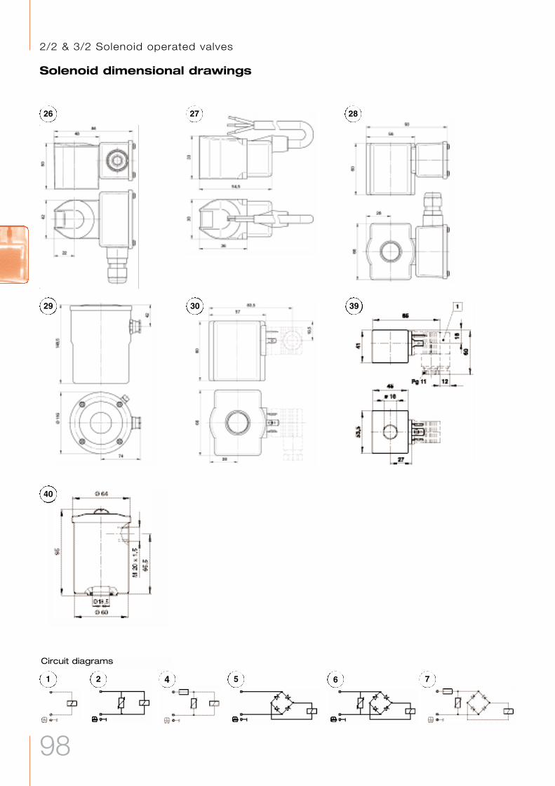
98
Solenoid dimensional drawings
26 27 28
29 30 39
40
Circuit diagrams
1 4 5 6 72
2/2 & 3/2 Solenoid operated valves

99