g1000 / gfc 700 post installation checkout...
TRANSCRIPT

190-00915-00 July 2009 Revision 6
G1000 / GFC 700 POST INSTALLATION CHECKOUT PROCEDURE
HAWKER BEECHCRAFT KING AIR 200/B200 SERIES
Page ii Post Installation Checkout Procedures Revision 6 King Air 200/B200 Series
190-00915-00
Copyright © 2009
Garmin Ltd. or its subsidiaries
All rights reserved
Except as expressly provided herein, no part of this manual may be reproduced, copied, transmitted, disseminated, downloaded or stored in any storage medium, for any purpose without the express prior written consent of Garmin. Garmin hereby grants permission to download a single copy of this manual and of any revision to this manual onto a hard drive or other electronic storage medium to be viewed and to print one copy of this manual or of any revision hereto, provided that such electronic or printed copy of this manual or revision must contain the complete text of this copyright notice and provided further that any unauthorized commercial distribution of this manual or any revision hereto is strictly prohibited.
Garmin International, Inc. 1200 E. 151st Street
Olathe, KS 66062 USA Telephone: 913.397.8200
www.garmin.com
Garmin (Europe) Ltd. Liberty House, Bulls Copse Road
Hounsdown Business Park Southampton, SO40 9RB, UK Phone: +44 (0) 23 8052 4000
Fax: +44 (0) 23 8052 4004
Garmin AT, Inc. 2345 Turner Rd., SE
Salem, OR 97302 USA Telephone: 503.581.8101
RECORD OF REVISIONS
Revision Revision Date Description ECO #
4 12/18/08 Corrected clerical errors throughout document 58612
5 2/13/09 Updated sections throughout document based on feedback from conformity inspection. 59741
6 7/17/09 Add GSM 86 servo gearbox, Radio Altimeter and TAWS-A options 61769
DOCUMENT PAGINATION
Section Pagination
T.O.C., Intro i-viii 1 1-1 to 1-12 2 2-1 to 2-30 3 3-1 to 3-38 4 4-1 to 4-6 5 5-1 to 5-10 6 6-1 to 6-6 7 7-1 to 7-6 8 8-1 to 8-6 9 9-1
Post Installation Checkout Procedures Page iii King Air 200/B200 Series Revision 6 190-00915-00
INFORMATION SUBJECT TO EXPORT CONTROL LAWS
This document may contain information which is subject to the Export Administration Regulations (“EAR”) issued by the United States Department of Commerce (15 CFR, Chapter VII Subchapter C) and which may not be exported, released or disclosed to foreign nationals inside or outside the United States without first obtaining an export license. The preceding statement is required to be included on any and all reproductions in whole or in part of this manual. This product, its packaging, and its components contain chemicals known to the State of California to cause cancer, birth defects, or reproductive harm. This Notice is being provided in accordance with California's Proposition 65. If you have any questions or would like additional information, please refer to our web site at www.garmin.com/prop65.
The GDU 1040A PFDs and GDU 1500 MFD use a lens coated with a special anti-reflective coating that is very sensitive to skin oils, waxes and abrasive cleaners. CLEANERS CONTAINING AMMONIA WILL HARM THE ANTI-REFLECTIVE COATING. It is very important to clean the lens using a clean, lint-free cloth and an eyeglass lens cleaner that is specified as safe for anti-reflective coatings
All G1000 screen shots used in this document are current at the time of initial publication. Screen shots are intended to provide visual reference only. All information depicted in screen shots, including software file names, versions and part numbers, is subject to change and may not be up to date.
CAUTION
WARNING
IMPORTANT

Page iv Post Installation Checkout Procedures Revision 6 King Air 200/B200 Series 190-00915-00
This page intentionally left blank

Post Installation Checkout Procedures Page v King Air 200/B200 Series Revision 6 190-00915-00
TABLE OF CONTENTS
PARAGRAPH PAGE
1 INTRODUCTION................................................................................................................................1-1 1.1 Scope ............................................................................................................................................1-1 1.2 Organization..................................................................................................................................1-1 1.3 Reference Documents ..................................................................................................................1-2 1.4 System Description .......................................................................................................................1-3 1.5 G1000 Control Interface................................................................................................................1-6 1.6 G1000 Software Image .................................................................................................................1-8 1.7 Software Loader Card Creation ....................................................................................................1-9 1.8 Configuration Mode.....................................................................................................................1-12 2 POST INSTALLATION PROCEDURES ............................................................................................2-1 2.1 Required Test Equipment .............................................................................................................2-1 2.2 System Preparation.......................................................................................................................2-1 2.3 Power Checks ...............................................................................................................................2-2 2.4 Stray Voltage Checks....................................................................................................................2-4 2.5 G1000 Hardware/Software Compatibility Check ..........................................................................2-4 2.6 G1000 Software/Configuration Procedure....................................................................................2-5 2.7 System Power Up .........................................................................................................................2-6 2.8 Software Load Confirmation .........................................................................................................2-9 2.9 TAWS-A Support Configuration ..................................................................................................2-11 2.10 TAWS-A Voice No Callout Option Configuration ........................................................................2-12 2.11 TAWS-A Voice Callout Option Configuration..............................................................................2-13 2.12 ADF Option Configuration...........................................................................................................2-14 2.13 DME Option Configuration ..........................................................................................................2-15 2.14 RAD ALT Option Configuration...................................................................................................2-16 2.15 Traffic System Option Configuration ...........................................................................................2-17 2.16 StormScope (WX-500) Option Configuration..............................................................................2-19 2.17 FliteCharts Configuration ............................................................................................................2-21 2.18 ChartView Option Configuration .................................................................................................2-21 2.19 TAWS-B Enable ..........................................................................................................................2-22 2.20 TAWS-A Enable ..........................................................................................................................2-23 2.21 Terrain/Obstacle Database Loading ...........................................................................................2-24 2.22 SVS/Pathways Enable ................................................................................................................2-24 2.23 Aircraft Registration Number Entry .............................................................................................2-25 2.24 Navigation Database Loading.....................................................................................................2-26 2.25 Clearing Default User Settings....................................................................................................2-27 2.26 System Communication Hierarchy..............................................................................................2-27 2.27 Software/Configuration Troubleshooting.....................................................................................2-28 3 G1000 INITIAL SYSTEM TESTING...................................................................................................3-1 3.1 Aircraft Systems Checks...............................................................................................................3-1 3.2 Electrical Power Distribution Testing ............................................................................................3-1 3.3 Electrical Load Test Procedures ...................................................................................................3-4 3.4 In-Flight Entertainment Bus (IFE) Voltage Checks .......................................................................3-7 3.5 Annunciator Checks......................................................................................................................3-8 3.6 Lighting Checks.............................................................................................................................3-9 3.7 Discrete Checks ..........................................................................................................................3-10 3.8 Display Testing............................................................................................................................3-13 3.9 GPS Signal Acquisiton................................................................................................................3-17 3.10 GMA 1347D Testing....................................................................................................................3-18 3.11 VHF COMM Operational Check..................................................................................................3-19 3.12 Marker Beacon Test....................................................................................................................3-19 3.13 VHF COM Interference Test .......................................................................................................3-19 3.14 VOR/LOC/GS Test......................................................................................................................3-20 3.15 COM Antenna VSWR Checks ....................................................................................................3-21 3.16 GTX 33( ) Testing........................................................................................................................3-21
Page vi Post Installation Checkout Procedures Revision 6 King Air 200/B200 Series 190-00915-00
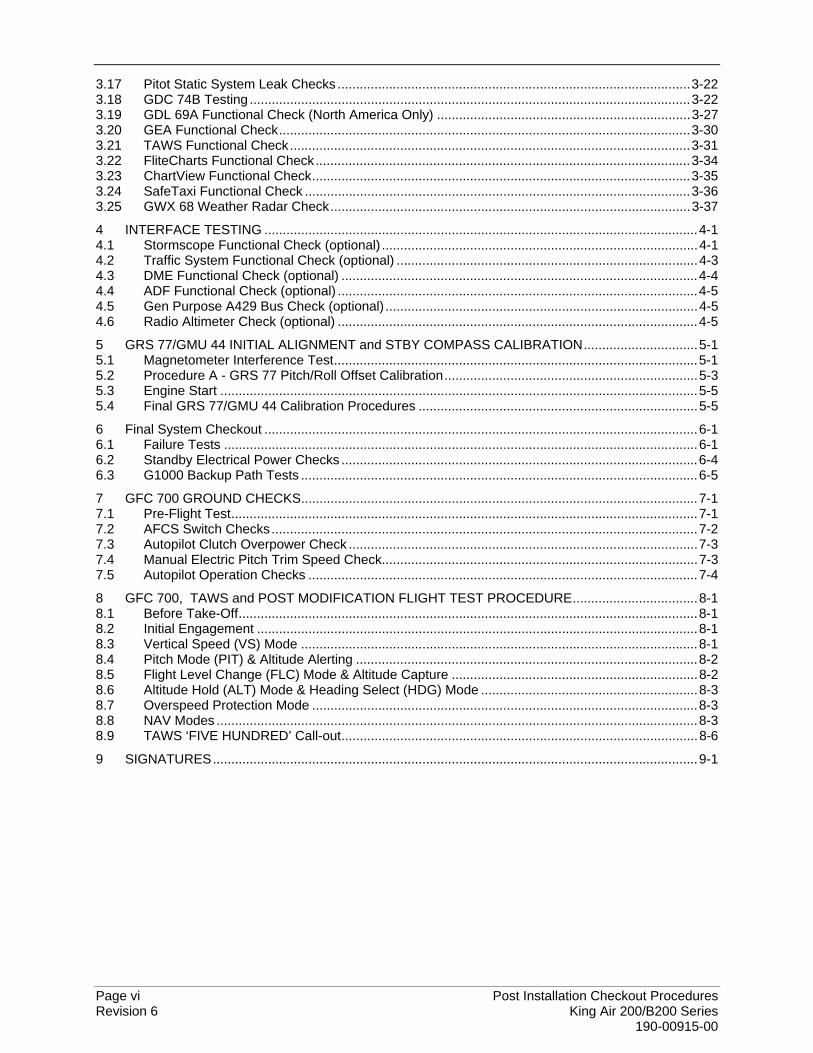
3.17 Pitot Static System Leak Checks ................................................................................................3-22 3.18 GDC 74B Testing ........................................................................................................................3-22 3.19 GDL 69A Functional Check (North America Only) .....................................................................3-27 3.20 GEA Functional Check................................................................................................................3-30 3.21 TAWS Functional Check.............................................................................................................3-31 3.22 FliteCharts Functional Check......................................................................................................3-34 3.23 ChartView Functional Check.......................................................................................................3-35 3.24 SafeTaxi Functional Check .........................................................................................................3-36 3.25 GWX 68 Weather Radar Check..................................................................................................3-37 4 INTERFACE TESTING ......................................................................................................................4-1 4.1 Stormscope Functional Check (optional) ......................................................................................4-1 4.2 Traffic System Functional Check (optional) ..................................................................................4-3 4.3 DME Functional Check (optional) .................................................................................................4-4 4.4 ADF Functional Check (optional) ..................................................................................................4-5 4.5 Gen Purpose A429 Bus Check (optional) .....................................................................................4-5 4.6 Radio Altimeter Check (optional) ..................................................................................................4-5 5 GRS 77/GMU 44 INITIAL ALIGNMENT and STBY COMPASS CALIBRATION...............................5-1 5.1 Magnetometer Interference Test...................................................................................................5-1 5.2 Procedure A - GRS 77 Pitch/Roll Offset Calibration.....................................................................5-3 5.3 Engine Start ..................................................................................................................................5-5 5.4 Final GRS 77/GMU 44 Calibration Procedures ............................................................................5-5 6 Final System Checkout ......................................................................................................................6-1 6.1 Failure Tests .................................................................................................................................6-1 6.2 Standby Electrical Power Checks .................................................................................................6-4 6.3 G1000 Backup Path Tests ............................................................................................................6-5 7 GFC 700 GROUND CHECKS............................................................................................................7-1 7.1 Pre-Flight Test...............................................................................................................................7-1 7.2 AFCS Switch Checks....................................................................................................................7-2 7.3 Autopilot Clutch Overpower Check ...............................................................................................7-3 7.4 Manual Electric Pitch Trim Speed Check......................................................................................7-3 7.5 Autopilot Operation Checks ..........................................................................................................7-4 8 GFC 700, TAWS and POST MODIFICATION FLIGHT TEST PROCEDURE..................................8-1 8.1 Before Take-Off.............................................................................................................................8-1 8.2 Initial Engagement ........................................................................................................................8-1 8.3 Vertical Speed (VS) Mode ............................................................................................................8-1 8.4 Pitch Mode (PIT) & Altitude Alerting .............................................................................................8-2 8.5 Flight Level Change (FLC) Mode & Altitude Capture ...................................................................8-2 8.6 Altitude Hold (ALT) Mode & Heading Select (HDG) Mode ...........................................................8-3 8.7 Overspeed Protection Mode .........................................................................................................8-3 8.8 NAV Modes ...................................................................................................................................8-3 8.9 TAWS ‘FIVE HUNDRED’ Call-out.................................................................................................8-6 9 SIGNATURES....................................................................................................................................9-1
Post Installation Checkout Procedures Page vii King Air 200/B200 Series Revision 6 190-00915-00
LIST OF FIGURES
FIGURE PAGE
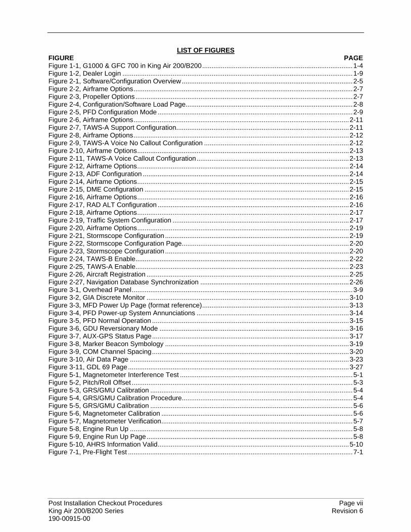
Figure 1-1, G1000 & GFC 700 in King Air 200/B200.................................................................................1-4Figure 1-2, Dealer Login ............................................................................................................................1-9Figure 2-1, Software/Configuration Overview............................................................................................2-5Figure 2-2, Airframe Options......................................................................................................................2-7Figure 2-3, Propeller Options.....................................................................................................................2-7Figure 2-4, Configuration/Software Load Page..........................................................................................2-8Figure 2-5, PFD Configuration Mode .........................................................................................................2-9Figure 2-6, Airframe Options....................................................................................................................2-11Figure 2-7, TAWS-A Support Configuration.............................................................................................2-11Figure 2-8, Airframe Options....................................................................................................................2-12Figure 2-9, TAWS-A Voice No Callout Configuration ..............................................................................2-12Figure 2-10, Airframe Options..................................................................................................................2-13Figure 2-11, TAWS-A Voice Callout Configuration..................................................................................2-13Figure 2-12, Airframe Options..................................................................................................................2-14Figure 2-13, ADF Configuration ...............................................................................................................2-14Figure 2-14, Airframe Options..................................................................................................................2-15Figure 2-15, DME Configuration ..............................................................................................................2-15Figure 2-16, Airframe Options..................................................................................................................2-16Figure 2-17, RAD ALT Configuration .......................................................................................................2-16Figure 2-18, Airframe Options..................................................................................................................2-17Figure 2-19, Traffic System Configuration ...............................................................................................2-17Figure 2-20, Airframe Options..................................................................................................................2-19Figure 2-21, Stormscope Configuration ...................................................................................................2-19Figure 2-22, Stormscope Configuration Page..........................................................................................2-20Figure 2-23, Stormscope Configuration ...................................................................................................2-20Figure 2-24, TAWS-B Enable...................................................................................................................2-22Figure 2-25, TAWS-A Enable...................................................................................................................2-23Figure 2-26, Aircraft Registration .............................................................................................................2-25Figure 2-27, Navigation Database Synchronization ................................................................................2-26Figure 3-1, Overhead Panel.......................................................................................................................3-9Figure 3-2, GIA Discrete Monitor .............................................................................................................3-10Figure 3-3, MFD Power Up Page (format reference)...............................................................................3-13Figure 3-4, PFD Power-up System Annunciations ..................................................................................3-14Figure 3-5, PFD Normal Operation ..........................................................................................................3-15Figure 3-6, GDU Reversionary Mode ......................................................................................................3-16Figure 3-7, AUX-GPS Status Page..........................................................................................................3-17Figure 3-8, Marker Beacon Symbology ...................................................................................................3-19Figure 3-9, COM Channel Spacing..........................................................................................................3-20Figure 3-10, Air Data Page ......................................................................................................................3-23Figure 3-11, GDL 69 Page.......................................................................................................................3-27Figure 5-1, Magnetometer Interference Test .............................................................................................5-1Figure 5-2, Pitch/Roll Offset .......................................................................................................................5-3Figure 5-3, GRS/GMU Calibration .............................................................................................................5-4Figure 5-4, GRS/GMU Calibration Procedure............................................................................................5-4Figure 5-5, GRS/GMU Calibration .............................................................................................................5-6Figure 5-6, Magnetometer Calibration .......................................................................................................5-6Figure 5-7, Magnetometer Verification.......................................................................................................5-7Figure 5-8, Engine Run Up ........................................................................................................................5-8Figure 5-9, Engine Run Up Page...............................................................................................................5-8Figure 5-10, AHRS Information Valid.......................................................................................................5-10Figure 7-1, Pre-Flight Test .........................................................................................................................7-1

Page viii Post Installation Checkout Procedures Revision 6 King Air 200/B200 Series 190-00915-00
LIST OF TABLES
TABLE PAGE
Table 1-1, Effectivity...................................................................................................................................1-1Table 1-2, Referenced Documentation ......................................................................................................1-2Table 2-1, Airframe Power Switches..........................................................................................................2-1Table 2-2, Installed Equipment ..................................................................................................................2-2Table 2-3, Power and Ground Specifications ............................................................................................2-3Table 2-4, Successful Criteria..................................................................................................................2-27Table 2-5, Troubleshooting ......................................................................................................................2-29Table 3-1, Measured DC Electrical Loads .................................................................................................3-7Table 3-2, GIA 1 Discretes.......................................................................................................................3-10Table 3-3, GIA 2 Discretes.......................................................................................................................3-11Table 3-4, Flap/Gear Discretes GIA 1......................................................................................................3-12Table 3-5, Flap/Gear Discretes GIA 2......................................................................................................3-12Table 3-6, Altitude/Airspeed.....................................................................................................................3-25Table 3-7, Vertical Speed.........................................................................................................................3-26Table 5-1, Magnetometer Interference Test Sequence .............................................................................5-2Table 6-1, Failure Tests .............................................................................................................................6-3Table 6-2, Standby Power Tests................................................................................................................6-4
Post Installation Checkout Procedures Page 1-1 King Air 200/B200 Series Revision 6 190-00915-00
1 INTRODUCTION
1.1 Scope
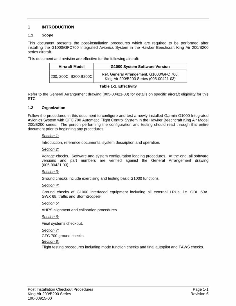
This document presents the post-installation procedures which are required to be performed after installing the G1000/GFC700 Integrated Avionics System in the Hawker Beechcraft King Air 200/B200 series aircraft.
This document and revision are effective for the following aircraft:
Aircraft Model G1000 System Software Version
200, 200C, B200,B200C Ref. General Arrangement, G1000/GFC 700, King Air 200/B200 Series (005-00421-03)
Table 1-1, Effectivity
Refer to the General Arrangement drawing (005-00421-03) for details on specific aircraft eligibility for this STC.
1.2 Organization
Follow the procedures in this document to configure and test a newly-installed Garmin G1000 Integrated Avionics System with GFC 700 Automatic Flight Control System in the Hawker Beechcraft King Air Model 200/B200 series. The person performing the configuration and testing should read through this entire document prior to beginning any procedures.
Section 1:
Introduction, reference documents, system description and operation.
Section 2:
Voltage checks. Software and system configuration loading procedures. At the end, all software versions and part numbers are verified against the General Arrangement drawing (005-00421-03).
Section 3:
Ground checks include exercising and testing basic G1000 functions.
Section 4:
Ground checks of G1000 interfaced equipment including all external LRUs, i.e. GDL 69A, GWX 68, traffic and StormScope®.
Section 5:
AHRS alignment and calibration procedures.
Section 6:
Final systems checkout.
Section 7: GFC 700 ground checks.
Section 8: Flight testing procedures including mode function checks and final autopilot and TAWS checks.
Page 1-2 Post Installation Checkout Procedures Revision 6 King Air 200/B200 Series 190-00915-00
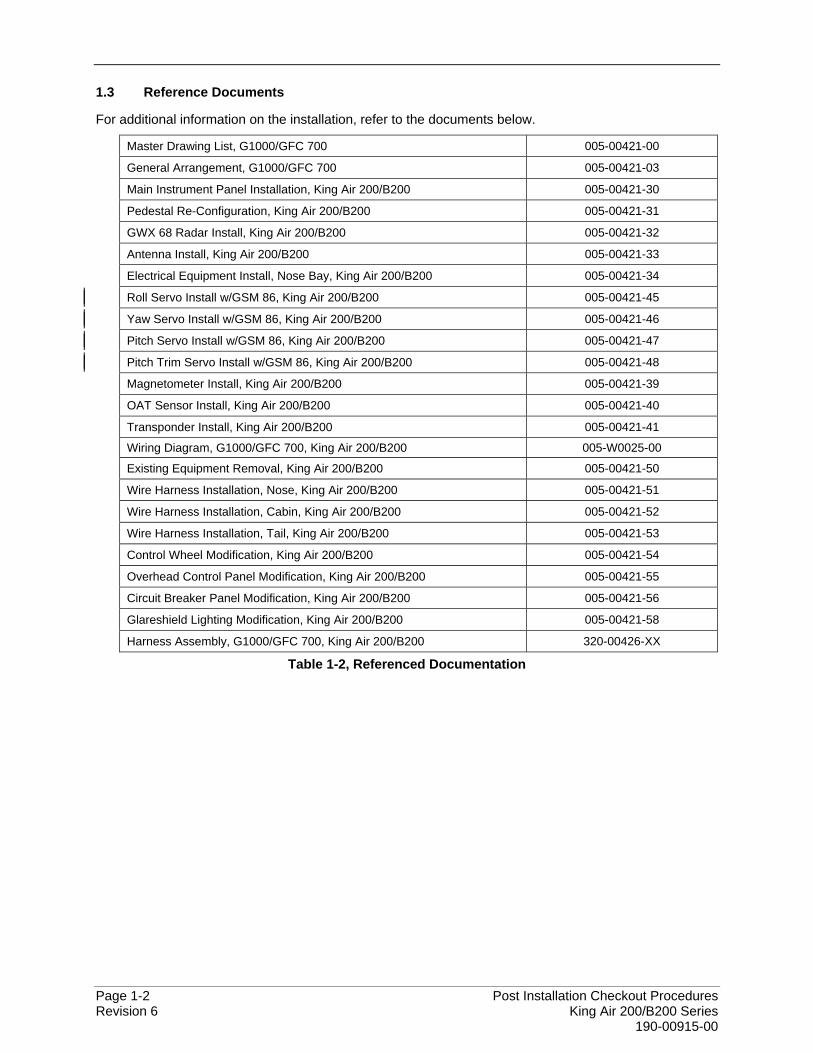
1.3 Reference Documents
For additional information on the installation, refer to the documents below.
Master Drawing List, G1000/GFC 700 005-00421-00
General Arrangement, G1000/GFC 700 005-00421-03
Main Instrument Panel Installation, King Air 200/B200 005-00421-30
Pedestal Re-Configuration, King Air 200/B200 005-00421-31
GWX 68 Radar Install, King Air 200/B200 005-00421-32
Antenna Install, King Air 200/B200 005-00421-33
Electrical Equipment Install, Nose Bay, King Air 200/B200 005-00421-34
Roll Servo Install w/GSM 86, King Air 200/B200 005-00421-45
Yaw Servo Install w/GSM 86, King Air 200/B200 005-00421-46
Pitch Servo Install w/GSM 86, King Air 200/B200 005-00421-47
Pitch Trim Servo Install w/GSM 86, King Air 200/B200 005-00421-48
Magnetometer Install, King Air 200/B200 005-00421-39
OAT Sensor Install, King Air 200/B200 005-00421-40
Transponder Install, King Air 200/B200 005-00421-41
Wiring Diagram, G1000/GFC 700, King Air 200/B200 005-W0025-00
Existing Equipment Removal, King Air 200/B200 005-00421-50
Wire Harness Installation, Nose, King Air 200/B200 005-00421-51
Wire Harness Installation, Cabin, King Air 200/B200 005-00421-52
Wire Harness Installation, Tail, King Air 200/B200 005-00421-53
Control Wheel Modification, King Air 200/B200 005-00421-54
Overhead Control Panel Modification, King Air 200/B200 005-00421-55
Circuit Breaker Panel Modification, King Air 200/B200 005-00421-56
Glareshield Lighting Modification, King Air 200/B200 005-00421-58
Harness Assembly, G1000/GFC 700, King Air 200/B200 320-00426-XX
Table 1-2, Referenced Documentation
Post Installation Checkout Procedures Page 1-3 King Air 200/B200 Series Revision 6 190-00915-00
1.4 System Description
1.4.1 Equipment
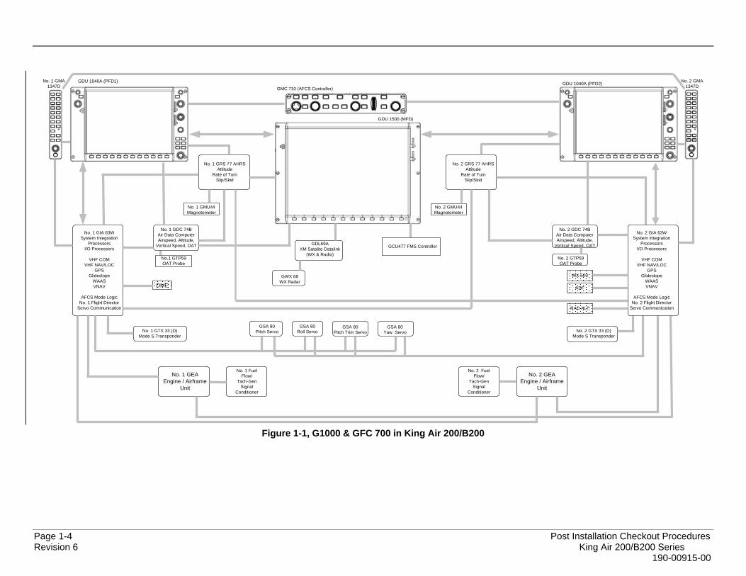
The G1000 and GFC 700 AFCS is comprised of the following equipment:
Control & Display: • Two GDU 1040A PFDs • GDU 1500 MFD • GCU 477 Remote Control Unit
Communication, Navigation, & Surveillance:
• Two GIA 63W Integrated Avionics Units • Two GMA 1347D Audio Panels • Two GTX 33 and/or GTX33D Mode S Transponders • GDL 69A Datalink • GWX 68 Weather Radar
Sensors:
• Two GDC 74B Air Data Computers (ADC) • Two GRS 77 Attitude & Heading Reference Systems (AHRS) • Two GMU 44 Magnetometers • Two GEA 71 Engine/Airframe Units • GEA engine parameter function supported by two Vibro-Meter Fuel Flow and Tach signal
conditioners. Autopilot:
• GMC 710 AFCS Mode Controller • GSA 80 Servos (yaw, pitch, roll) • GSA 80 High-speed servo (pitch trim) • GSM86 Servo Gearboxes
Page 1-4 Post Installation Checkout Procedures Revision 6 King Air 200/B200 Series 190-00915-00
GDU 1040A (PFD1)
GDU 1500 (MFD)
No. 1 GIA 63WSystem Integration
ProcessorsI/O Processors
VHF COMVHF NAV/LOC
GPSGlideslope
WAASVNAV
AFCS Mode Logic No. 1 Flight Director
Servo Communication
No. 1 GDC 74BAir Data Computer Airspeed, Altitude,
Vertical Speed, OAT
No. 1 GEAEngine / Airframe
Unit
GSA 80Roll Servo
GSA 80Pitch Trim Servo
GSA 80Pitch ServoNo. 1 GTX 33 (D)
Mode S Transponder
No. 2 GMA1347D
GDL69AXM Satalite Datalink
(WX & Radio)No.1 GTP59 OAT Probe
GMC 710 (AFCS Controller)
No. 1 GMU44Magnotometer
GSA 80Yaw Servo
DME
WX-500
No. 2 GIA 63WSystem Integration
ProcessorsI/O Processors
VHF COMVHF NAV/LOC
GPSGlideslope
WAASVNAV
AFCS Mode Logic No. 2 Flight Director
Servo Communication
No. 2 GDC 74BAir Data Computer Airspeed, Altitude,
Vertical Speed, OAT
No. 2 GEAEngine / Airframe
Unit
No. 2 GRS 77 AHRSAttitude
Rate of TurnSlip/Skid
No. 1 GRS 77 AHRSAttitude
Rate of TurnSlip/Skid
No. 2 GMU44Magnotometer
No. 2 GTX 33 (D)Mode S Transponder
No. 2 GTP59 OAT Probe
GDU 1040A (PFD2)No. 1 GMA1347D
GWX 68WX Radar
No. 1 Fuel Flow/
Tach-Gen Signal
Conditioner
ADFADF
No. 2 Fuel Flow/
Tach-Gen Signal
Conditioner
ADFRAD ALT
GCU477 FMS Controller
Figure 1-1, G1000 & GFC 700 in King Air 200/B200

Post Installation Checkout Procedures Page 1-5 King Air 200/B200 Series Revision 6 190-00915-00
1.4.2 GFC 700 Operation
The GFC 700 is a fail-passive digital flight control system composed of multiple G1000 LRUs and servos. The following functions are provided by the GFC 700 in this installation:
• Flight Director • Autopilot • Pitch Trim • Yaw Damper
Flight Director:
The Flight Directors operate within the GIA 63Ws and use data from the G1000 system, including air, attitude and flight data, to calculate commands for display to the pilot and for the Autopilot. Flight director command bars and mode annunciations are sent to the PFDs through a high-speed Ethernet connection for display to the pilot and copilot. The flight directors operate independently of the autopilot and allow the pilot to hand-fly the command bars, if desired. The GMC 710 allows the pilot to switch the active director between flight director #1 (GIA1) and flight director #2 (GIA2).
Autopilot:
The autopilot operates within one high-speed GSA 80 servo (pitch trim) and three GSA 80 servos (pitch, roll and yaw). Flight director data is processed within the servos and turned into aircraft flight control surface commands. The autopilot cannot operate unless the flight director is engaged.
Manual Electric Trim: When the autopilot is not engaged, the pitch trim servo may be used to provide a Manual Electric Pitch Trim (MEPT) function. This allows the pilot or co-pilot to adjust pitch trim from the PITCH TRIM switch on the control wheel in lieu of using the elevator trim wheel. Trim speeds are scheduled to provide easier control over a wide speed or configuration range. The PITCH TRIM switch is split into two halves. The left half arms MEPT. The right half controls direction. Both halves must be actuated at the same time to command the pitch trim servo to operate. If only one half of the PITCH TRIM switch is actuated for more than 3 seconds, a red PTRM message will appear on the PFDs.
Yaw Damper: The yaw damper reduces Dutch roll tendencies and coordinates turns. It can operate independently of the autopilot and may be used during normal hand-flight maneuvers.
Page 1-6 Post Installation Checkout Procedures Revision 6 King Air 200/B200 Series 190-00915-00
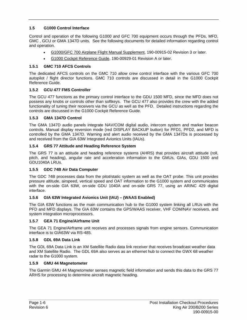
1.5 G1000 Control Interface
Control and operation of the following G1000 and GFC 700 equipment occurs through the PFDs, MFD, GMC , GCU or GMA 1347D units. See the following documents for detailed information regarding control and operation.
• G1000/GFC 700 Airplane Flight Manual Supplement, 190-00915-02 Revision 3 or later. • G1000 Cockpit Reference Guide, 190-00929-01 Revision A or later.
1.5.1 GMC 710 AFCS Controls
The dedicated AFCS controls on the GMC 710 allow crew control interface with the various GFC 700 autopilot / flight director functions. GMC 710 controls are discussed in detail in the G1000 Cockpit Reference Guide.
1.5.2 GCU 477 FMS Controller
The GCU 477 functions as the primary control interface to the GDU 1500 MFD, since the MFD does not possess any knobs or controls other than softkeys. The GCU 477 also provides the crew with the added functionality of tuning their receivers via the GCU as well as the PFD. Detailed instructions regarding the controls are discussed in the G1000 Cockpit Reference Guide.
1.5.3 GMA 1347D Control
The GMA 1347D audio panels integrate NAV/COM digital audio, intercom system and marker beacon controls. Manual display reversion mode (red DISPLAY BACKUP button) for PFD1, PFD2, and MFD is controlled by the GMA 1347D. Warning and alert audio received by the GMA 1347Ds is processed by and received from the GIA 63W Integrated Avionics Units (IAUs).
1.5.4 GRS 77 Attitude and Heading Reference System
The GRS 77 is an attitude and heading reference systems (AHRS) that provides aircraft attitude (roll, pitch, and heading), angular rate and acceleration information to the GMUs, GIAs, GDU 1500 and GDU1040A LRUs.
1.5.5 GDC 74B Air Data Computer
The GDC 74B processes data from the pitot/static system as well as the OAT probe. This unit provides pressure altitude, airspeed, vertical speed and OAT information to the G1000 system and communicates with the on-side GIA 63W, on-side GDU 1040A and on-side GRS 77, using an ARINC 429 digital interface.
1.5.6 GIA 63W Integrated Avionics Unit (IAU) – (WAAS Enabled)
The GIA 63W functions as the main communication hub to the G1000 system linking all LRUs with the PFD and MFD displays. The GIA 63W contains the GPS/WAAS receiver, VHF COM/NAV receivers, and system integration microprocessors.
1.5.7 GEA 71 Engine/Airframe Unit
The GEA 71 Engine/Airframe unit receives and processes signals from engine sensors. Communication interface is to GIA63W via RS-485.
1.5.8 GDL 69A Data Link
The GDL 69A Data Link is an XM Satellite Radio data link receiver that receives broadcast weather data and XM Satellite Radio. The GDL 69A also serves as an ethernet hub to connect the GWX 68 weather radar to the G1000 system.
1.5.9 GMU 44 Magnetometer
The Garmin GMU 44 Magnetometer senses magnetic field information and sends this data to the GRS 77 ARHS for processing to determine aircraft magnetic heading.

Post Installation Checkout Procedures Page 1-7 King Air 200/B200 Series Revision 6 190-00915-00
1.5.10 GTX 33(D) Mode S Transponder
The Garmin GTX 33 (or GTX33D diversity) Mode S Transponder provides Mode A, C, and S capabilities for ATC, and TIS surveillance requirements and extended squitter capability. The GTX 33s interface with the No. 1 and No. 2 GIA63W LRUs via RS-232.
1.5.11 GSA 80 Servo Actuator
The Garmin GSA 80 Servo Actuator is an electromechanical unit that will provide pitch, roll and yaw damp and turn coordination.
1.5.12 GSA 80 High Speed Servo Actuator
The Garmin GSA 80 High Speed Servo Actuator is an electromechanical unit that will provide automatic control of the pitch trim.
1.5.13 GSM 86 Servo Gearbox
The Garmin 86 Servo Gearboxes are attached to a mount bracket and are responsible for transferring the output torque of the GSA 80 servo actuators to the mechanical flight control surface linkage.
1.5.14 GWX 68 Weather Radar
The GWX68 Airborne Weather Radar is a microprocessor-based Line Replaceable Unit that outputs weather radar data to the MFD through the GDL69 via an Ethernet high speed data bus.

Page 1-8 Post Installation Checkout Procedures Revision 6 King Air 200/B200 Series 190-00915-00
1.6 G1000 Software Image
All software and configuration files were certified by Garmin as part of the FAA-approved Type Design data. Approved software and hardware definitions for each STC Configuration are defined on the General Arrangement drawing 005-00421-03.
G1000 software and configuration files are controlled via the approved software image part number listed on the General Arrangement drawing 005-00421-03. This software image is loaded into the G1000 using a software loader card. The installer shall create this software loader card by downloading the approved software image in accordance with Section 1.7.
NOTE Only SanDisk and Toshiba brand SD cards are recommended for use with the G1000 system.
IMPORTANT! To satisfy the G1000/GFC700 STC requirements for the 200 / B200 series aircraft, it is critical that the technician installs the correct software image part number when servicing the G1000 system. Approved software image part numbers are defined on the appropriate General Arrangement drawing (see 005-00421-03).
CAUTION: Be cautious when using software loader cards during maintenance. The G1000 system immediately initializes the card upon power-up. On-screen prompts must be given careful attention in order to avoid potential loss of data. Always read through procedures given in Sections 2.5 to 2.24, before attempting to use the software loader cards.
Post Installation Checkout Procedures Page 1-9 King Air 200/B200 Series Revision 6 190-00915-00
1.7 Software Loader Card Creation
The software image is an executable self-extracting file which builds the correct file structure onto an SD card for use loading software to the G1000 and GFC700. To obtain the current file follow the procedures outlined below.
NOTE In order to create a 200/B200 loader card, the installer completing these procedures must be an authorized King Air 200/B200 service center to gain access to the necessary data via the Garmin website.
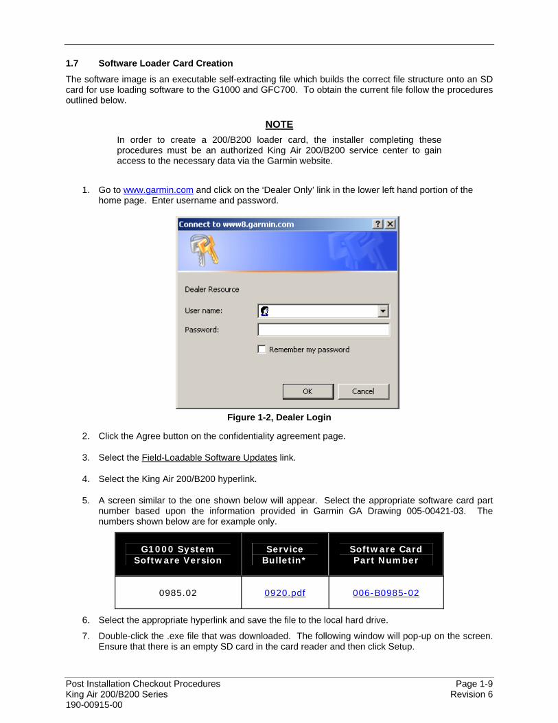
1. Go to www.garmin.com and click on the ‘Dealer Only’ link in the lower left hand portion of the home page. Enter username and password.
Figure 1-2, Dealer Login
2. Click the Agree button on the confidentiality agreement page.
3. Select the Field-Loadable Software Updates link.
4. Select the King Air 200/B200 hyperlink.
5. A screen similar to the one shown below will appear. Select the appropriate software card part number based upon the information provided in Garmin GA Drawing 005-00421-03. The numbers shown below are for example only.
G1000 System Software Version
Service Bulletin*
Software Card Part Number
0985.02 0920.pdf 006-B0985-02
6. Select the appropriate hyperlink and save the file to the local hard drive.
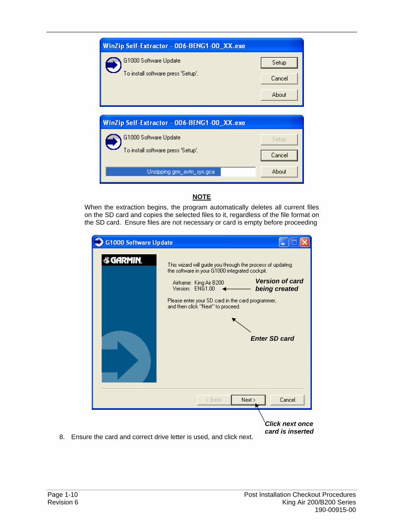
7. Double-click the .exe file that was downloaded. The following window will pop-up on the screen. Ensure that there is an empty SD card in the card reader and then click Setup.
Page 1-10 Post Installation Checkout Procedures Revision 6 King Air 200/B200 Series 190-00915-00
NOTE When the extraction begins, the program automatically deletes all current files on the SD card and copies the selected files to it, regardless of the file format on the SD card. Ensure files are not necessary or card is empty before proceeding
8. Ensure the card and correct drive letter is used, and click next.
Version of card being created
Enter SD card
Click next once card is inserted
Post Installation Checkout Procedures Page 1-11 King Air 200/B200 Series Revision 6 190-00915-00
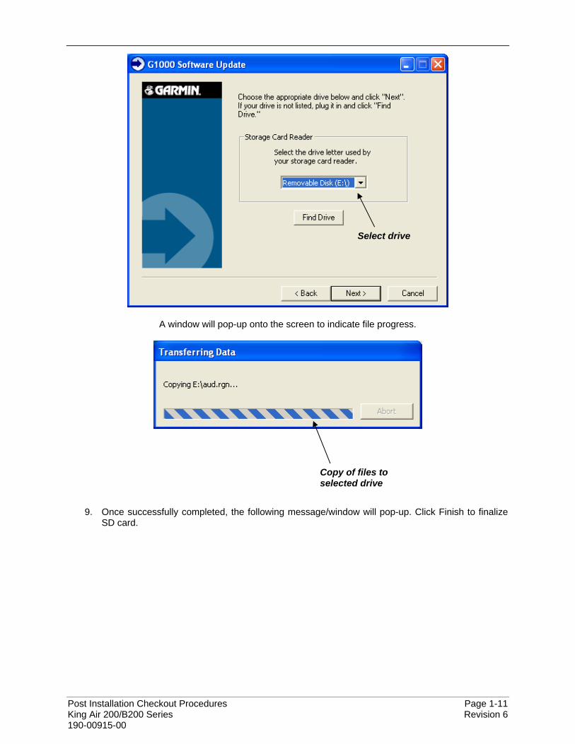
A window will pop-up onto the screen to indicate file progress.
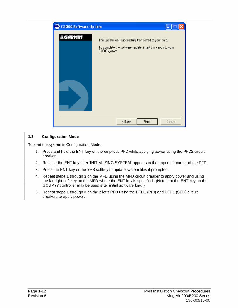
9. Once successfully completed, the following message/window will pop-up. Click Finish to finalize SD card.
Select drive
Copy of files to selected drive
Page 1-12 Post Installation Checkout Procedures Revision 6 King Air 200/B200 Series 190-00915-00
1.8 Configuration Mode
To start the system in Configuration Mode:
1. Press and hold the ENT key on the co-pilot’s PFD while applying power using the PFD2 circuit breaker.
2. Release the ENT key after ‘INITIALIZING SYSTEM’ appears in the upper left corner of the PFD.
3. Press the ENT key or the YES softkey to update system files if prompted.
4. Repeat steps 1 through 3 on the MFD using the MFD circuit breaker to apply power and using the far right soft key on the MFD where the ENT key is specified. (Note that the ENT key on the GCU 477 controller may be used after initial software load.)
5. Repeat steps 1 through 3 on the pilot’s PFD using the PFD1 (PRI) and PFD1 (SEC) circuit breakers to apply power.
Post Installation Checkout Procedures Page 2-1 King Air 200/B200 Series Revision 6 190-00915-00
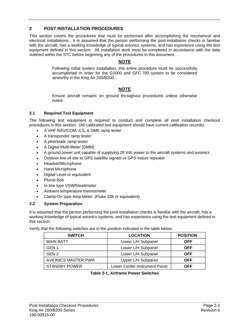
2 POST INSTALLATION PROCEDURES This section covers the procedures that must be performed after accomplishing the mechanical and electrical installations. It is assumed that the person performing the post-installation checks is familiar with the aircraft, has a working knowledge of typical avionics systems, and has experience using the test equipment defined in this section. All installation work must be completed in accordance with the data outlined within the STC before beginning any of the procedures in this document.
NOTE Following initial system installation, this entire procedure must be successfully accomplished in order for the G1000 and GFC 700 system to be considered airworthy in the King Air 200/B200.
NOTE
Ensure aircraft remains on ground throughout procedures unless otherwise noted.
2.1 Required Test Equipment
The following test equipment is required to conduct and complete all post installation checkout procedures in this section: (All calibrated test equipment should have current calibration records)
• A VHF NAV/COM, ILS, & DME ramp tester • A transponder ramp tester • A pitot/static ramp tester • A Digital Multi-Meter (DMM) • A ground power unit capable of supplying 28 Vdc power to the aircraft systems and avionics • Outdoor line-of-site to GPS satellite signals or GPS indoor repeater • Headset/Microphone • Hand Microphone • Digital Level or equivalent • Plumb Bob • In-line type VSWR/wattmeter • Ambient temperature thermometer • Clamp-On type Amp Meter (Fluke 336 or equivalent)
2.2 System Preparation
It is assumed that the person performing the post-installation checks is familiar with the aircraft, has a working knowledge of typical avionics systems, and has experience using the test equipment defined in this section.
Verify that the following switches are in the position indicated in the table below:
SWITCH LOCATION POSITION MAIN BATT Lower L/H Subpanel OFF GEN 1 Lower L/H Subpanel OFF GEN 2 Lower L/H Subpanel OFF AVIONICS MASTER PWR Upper L/H Subpanel OFF STANDBY POWER Lower Center Instrument Panel OFF
Table 2-1, Airframe Power Switches
Page 2-2 Post Installation Checkout Procedures Revision 6 King Air 200/B200 Series 190-00915-00
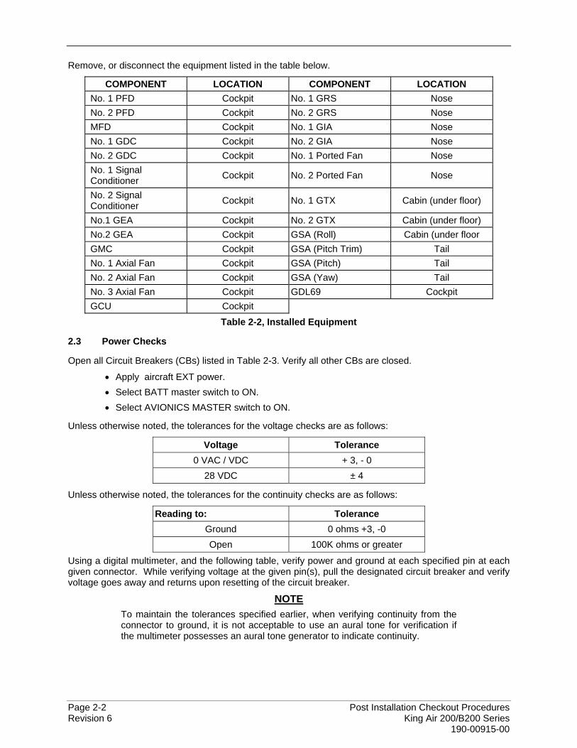
Remove, or disconnect the equipment listed in the table below.
COMPONENT LOCATION COMPONENT LOCATION No. 1 PFD Cockpit No. 1 GRS Nose No. 2 PFD Cockpit No. 2 GRS Nose MFD Cockpit No. 1 GIA Nose No. 1 GDC Cockpit No. 2 GIA Nose No. 2 GDC Cockpit No. 1 Ported Fan Nose No. 1 Signal Conditioner Cockpit No. 2 Ported Fan Nose
No. 2 Signal Conditioner Cockpit No. 1 GTX Cabin (under floor)
No.1 GEA Cockpit No. 2 GTX Cabin (under floor) No.2 GEA Cockpit GSA (Roll) Cabin (under floor GMC Cockpit GSA (Pitch Trim) Tail No. 1 Axial Fan Cockpit GSA (Pitch) Tail No. 2 Axial Fan Cockpit GSA (Yaw) Tail No. 3 Axial Fan Cockpit GDL69 Cockpit GCU Cockpit
Table 2-2, Installed Equipment
2.3 Power Checks
Open all Circuit Breakers (CBs) listed in Table 2-3. Verify all other CBs are closed.
• Apply aircraft EXT power. • Select BATT master switch to ON. • Select AVIONICS MASTER switch to ON.
Unless otherwise noted, the tolerances for the voltage checks are as follows:
Voltage Tolerance 0 VAC / VDC + 3, - 0
28 VDC ± 4
Unless otherwise noted, the tolerances for the continuity checks are as follows:
Reading to: Tolerance Ground 0 ohms +3, -0 Open 100K ohms or greater
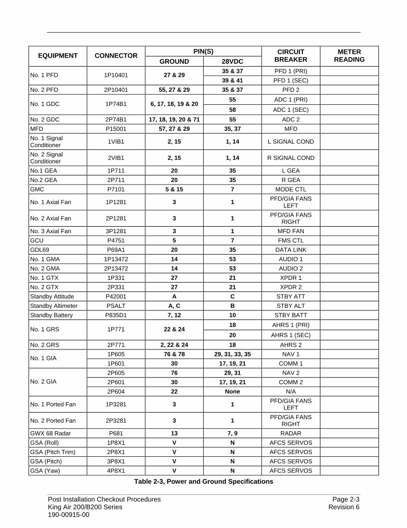
Using a digital multimeter, and the following table, verify power and ground at each specified pin at each given connector. While verifying voltage at the given pin(s), pull the designated circuit breaker and verify voltage goes away and returns upon resetting of the circuit breaker.
NOTE To maintain the tolerances specified earlier, when verifying continuity from the connector to ground, it is not acceptable to use an aural tone for verification if the multimeter possesses an aural tone generator to indicate continuity.
Post Installation Checkout Procedures Page 2-3 King Air 200/B200 Series Revision 6 190-00915-00
PIN(S) EQUIPMENT CONNECTOR
GROUND 28VDC CIRCUIT
BREAKER METER
READING 35 & 37 PFD 1 (PRI) No. 1 PFD 1P10401 27 & 29 39 & 41 PFD 1 (SEC)
No. 2 PFD 2P10401 55, 27 & 29 35 & 37 PFD 2 55 ADC 1 (PRI)
No. 1 GDC 1P74B1 6, 17, 18, 19 & 20 58 ADC 1 (SEC)
No. 2 GDC 2P74B1 17, 18, 19, 20 & 71 55 ADC 2 MFD P15001 57, 27 & 29 35, 37 MFD No. 1 Signal Conditioner 1VIB1 2, 15 1, 14 L SIGNAL COND
No. 2 Signal Conditioner 2VIB1 2, 15 1, 14 R SIGNAL COND
No.1 GEA 1P711 20 35 L GEA No.2 GEA 2P711 20 35 R GEA GMC P7101 5 & 15 7 MODE CTL
No. 1 Axial Fan 1P1281 3 1 PFD/GIA FANS LEFT
No. 2 Axial Fan 2P1281 3 1 PFD/GIA FANS RIGHT
No. 3 Axial Fan 3P1281 3 1 MFD FAN GCU P4751 5 7 FMS CTL GDL69 P69A1 20 35 DATA LINK No. 1 GMA 1P13472 14 53 AUDIO 1 No. 2 GMA 2P13472 14 53 AUDIO 2 No. 1 GTX 1P331 27 21 XPDR 1 No. 2 GTX 2P331 27 21 XPDR 2 Standby Attitude P42001 A C STBY ATT Standby Altimeter PSALT A, C B STBY ALT Standby Battery P835D1 7, 12 10 STBY BATT
18 AHRS 1 (PRI) No. 1 GRS 1P771 22 & 24
20 AHRS 1 (SEC) No. 2 GRS 2P771 2, 22 & 24 18 AHRS 2
1P605 76 & 78 29, 31, 33, 35 NAV 1 No. 1 GIA 1P601 30 17, 19, 21 COMM 1 2P605 76 29, 31 NAV 2 2P601 30 17, 19, 21 COMM 2 No. 2 GIA
2P604 22 None N/A
No. 1 Ported Fan 1P3281 3 1 PFD/GIA FANS LEFT
No. 2 Ported Fan 2P3281 3 1 PFD/GIA FANS RIGHT
GWX 68 Radar P681 13 7, 9 RADAR GSA (Roll) 1P8X1 V N AFCS SERVOS GSA (Pitch Trim) 2P8X1 V N AFCS SERVOS GSA (Pitch) 3P8X1 V N AFCS SERVOS GSA (Yaw) 4P8X1 V N AFCS SERVOS
Table 2-3, Power and Ground Specifications
Page 2-4 Post Installation Checkout Procedures Revision 6 King Air 200/B200 Series 190-00915-00
2.4 Stray Voltage Checks
Close all circuit breakers that remain open from the previous section.
• Apply aircraft EXT power. • Select BATT master switch to ON. • Select AVIONICS MASTER switch to ON.
Using a digital multimeter, conduct a stray voltage check on all connector pins associated with the G1000 and GFC700 system components. A separate check should be run for both AC and DC stray voltages. No voltage should be present.
IMPORTANT! If voltage is detected on a pin or connector other than those specified in Section 2.3, determine source of voltage and correct problem before continuing.
Upon successful completion of the power, ground, and stray voltage checks, pull (open) all circuit breakers listed in Table 2-3 and reinstall/reconnect the equipment specified in Table 2-2 before proceeding to the next section.
2.5 G1000 Hardware/Software Compatibility Check
Before installing hardware, the technician must first ensure that hardware part numbers are compatible with the G1000/200/B200 software image that is to be used. A software loader card is required to install software and configuration settings to a newly installed G1000 system. The part number of the software image used to create the loader card is directly associated with the combination of software file part numbers and version levels that are defined on Garmin drawing 005-00421-03. Should software part numbers or versions change, a new software image part number is issued. The G1000/GFC 700 General Arrangement (GA) drawing, Garmin Part Number 005-00421-03, shows all available combinations of hardware and software images. Using the GA drawing, the technician must verify that all hardware part numbers are compatible with the newly created loader card (See Section 1.7) to be used. The GA drawing allows the technician to correlate each LRU hardware part number to a compatible software image.
IMPORTANT!
After verifying hardware/loader card compatibility, record the software image part number and all LRU hardware part numbers in the appropriate aircraft records before proceeding.
NOTE Throughout the next section of this document, screen shots and examples are used to illustrate the software and configuration loading process. These screen shots are provided as reference only. Always refer to the General Arrangement drawing for the correct software file names, versions and part numbers.
Post Installation Checkout Procedures Page 2-5 King Air 200/B200 Series Revision 6 190-00915-00
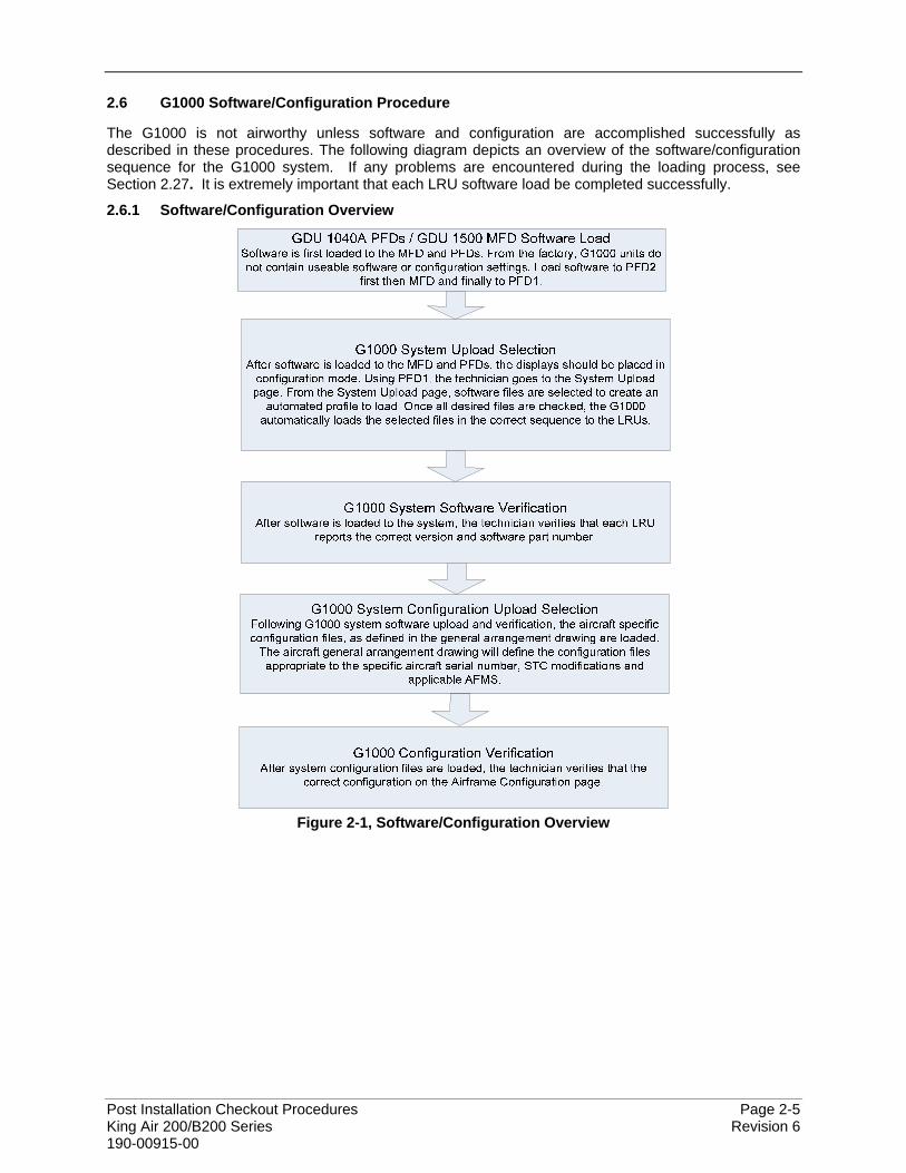
2.6 G1000 Software/Configuration Procedure
The G1000 is not airworthy unless software and configuration are accomplished successfully as described in these procedures. The following diagram depicts an overview of the software/configuration sequence for the G1000 system. If any problems are encountered during the loading process, see Section 2.27. It is extremely important that each LRU software load be completed successfully.
2.6.1 Software/Configuration Overview
Figure 2-1, Software/Configuration Overview
Page 2-6 Post Installation Checkout Procedures Revision 6 King Air 200/B200 Series 190-00915-00
2.7 System Power Up
Apply power to the G1000 by doing the following:
1. Connect a ground power unit to the external power receptacle, and turn on the ground power unit.
2. Set the BAT and AVIONICS MASTER switches to ON.
2.7.1 MFD & PFD Software Load
1. Pull the MFD, PFD1 (PRI), PFD1 (SEC) and PFD2 circuit breakers.
2. Insert the loader card into PFD2 top card slot.
3. While holding the ENT key on PFD2, restore power by closing the PFD2 circuit breaker.
4. When the words appear in the upper left corner of PFD2, release the PFD2 ENT key.
5. Press the PFD2 ENT key to acknowledge the following prompt (NOTE: A softkey labeled ‘YES’ appears in the lower right corner and may be used in lieu of the ENT key):
6. The following screen is displayed.
7. New software is loaded to PFD2. When complete, the PFD starts in configuration mode
displaying the “System Status” page . Do not remove power.
8. Remove the loader card from PFD2 and insert it into the top card slot on the MFD. Repeat Steps 3 through 6 for the MFD, using the far right softkey on the MFD in lieu of the ENT key where called out in Steps 3 through 6.
9. When MFD update is complete, it starts in the configuration mode. Do not remove power. Insert the loader card into PFD1 top card slot and repeat Steps 3 through 6 for PFD1. When complete, all three displays should be in configuration mode, with the Loader Card remaining in the top slot of PFD1.
IMPORTANT! For the rest of the software/configuration procedure, do not operate the MFD or PFD2 while loading software or configuration files unless specifically instructed to do so. A failed or cancelled load may result.
Post Installation Checkout Procedures Page 2-7 King Air 200/B200 Series Revision 6 190-00915-00
2.7.2 Airframe/Engine Configuration
NOTE If the aircraft being modified has incorporated any modifications beyond factory configuration that effect engine or airspeed limitations, your configuration may not be supported at this time. It is the responsibility of the installer to ensure compatibility with existing modifications.
1. Ensure loader card is inserted into top card slot of PFD1. On PFD1, select the “System Upload”
page using the PFD1 small FMS knob.
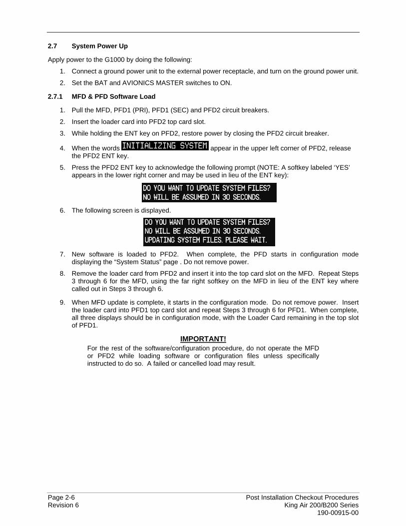
2. Activate the cursor and use the PFD1 small FMS knob to highlight “King Air 200 B200 Series Options” in the AIRFRAME field. Scroll small FMS knob to select the appropriate airframe and engine combination. Press the PFD1 ENT key to select the configuration .
Figure 2-2, Airframe Options
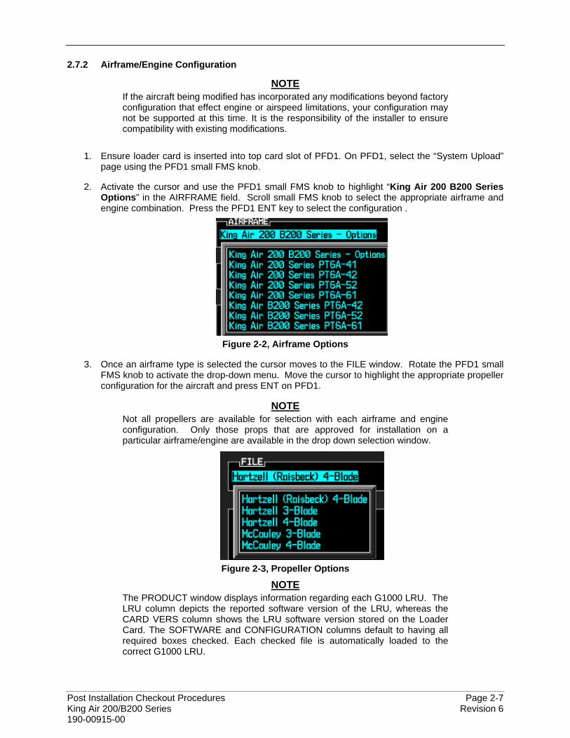
3. Once an airframe type is selected the cursor moves to the FILE window. Rotate the PFD1 small FMS knob to activate the drop-down menu. Move the cursor to highlight the appropriate propeller configuration for the aircraft and press ENT on PFD1.
NOTE Not all propellers are available for selection with each airframe and engine configuration. Only those props that are approved for installation on a particular airframe/engine are available in the drop down selection window.
Figure 2-3, Propeller Options
NOTE The PRODUCT window displays information regarding each G1000 LRU. The LRU column depicts the reported software version of the LRU, whereas the CARD VERS column shows the LRU software version stored on the Loader Card. The SOFTWARE and CONFIGURATION columns default to having all required boxes checked. Each checked file is automatically loaded to the correct G1000 LRU.

Page 2-8 Post Installation Checkout Procedures Revision 6 King Air 200/B200 Series 190-00915-00
Figure 2-4, Configuration/Software Load Page
4. Press the LOAD softkey.
5. Observe software loading progress and verify software load completes without errors as indicated by the following:
• Green “PASS” or White “N/A” in SOFTWARE and CONFIGURATION columns.
• “Upload Complete………….COMPLETE” in the summary box.
6. Press PFD1 ENT key to acknowledge the “Upload Complete” box.
7. Proceed to the next section.
Post Installation Checkout Procedures Page 2-9 King Air 200/B200 Series Revision 6 190-00915-00
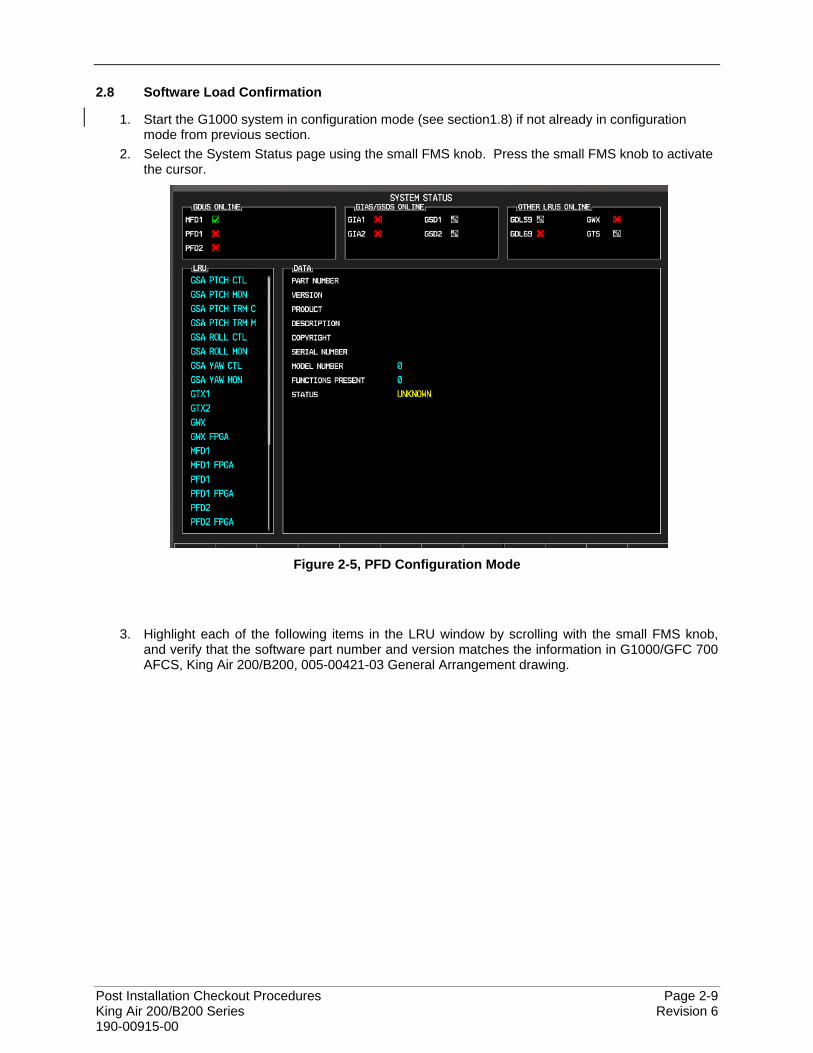
2.8 Software Load Confirmation
1. Start the G1000 system in configuration mode (see section1.8) if not already in configuration mode from previous section.
2. Select the System Status page using the small FMS knob. Press the small FMS knob to activate the cursor.
Figure 2-5, PFD Configuration Mode
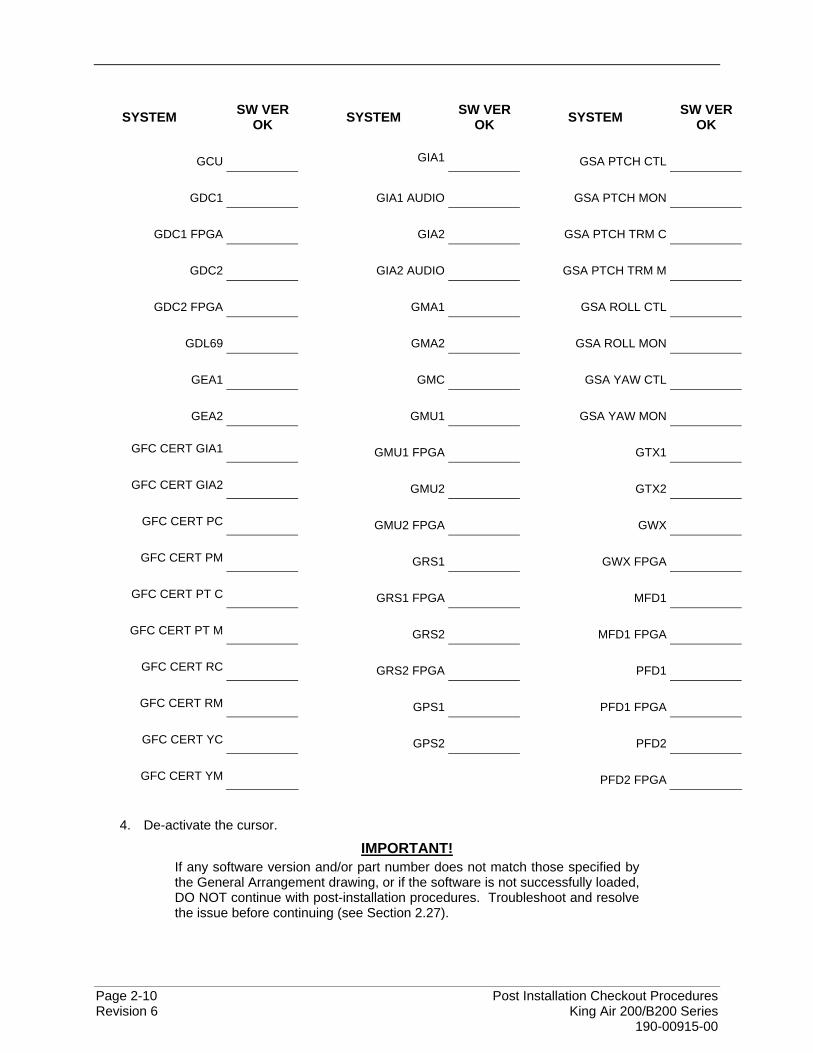
3. Highlight each of the following items in the LRU window by scrolling with the small FMS knob, and verify that the software part number and version matches the information in G1000/GFC 700 AFCS, King Air 200/B200, 005-00421-03 General Arrangement drawing.
Page 2-10 Post Installation Checkout Procedures Revision 6 King Air 200/B200 Series 190-00915-00
SYSTEM SW VER OK SYSTEM SW VER
OK SYSTEM SW VER OK
GCU GIA1 GSA PTCH CTL
GDC1 GIA1 AUDIO GSA PTCH MON
GDC1 FPGA GIA2 GSA PTCH TRM C
GDC2 GIA2 AUDIO GSA PTCH TRM M
GDC2 FPGA GMA1 GSA ROLL CTL
GDL69 GMA2 GSA ROLL MON
GEA1 GMC GSA YAW CTL
GEA2 GMU1 GSA YAW MON
GFC CERT GIA1 GMU1 FPGA GTX1
GFC CERT GIA2 GMU2 GTX2
GFC CERT PC GMU2 FPGA GWX
GFC CERT PM GRS1 GWX FPGA
GFC CERT PT C GRS1 FPGA MFD1
GFC CERT PT M GRS2 MFD1 FPGA
GFC CERT RC GRS2 FPGA PFD1
GFC CERT RM GPS1 PFD1 FPGA
GFC CERT YC GPS2 PFD2
GFC CERT YM PFD2 FPGA
4. De-activate the cursor.
IMPORTANT! If any software version and/or part number does not match those specified by the General Arrangement drawing, or if the software is not successfully loaded, DO NOT continue with post-installation procedures. Troubleshoot and resolve the issue before continuing (see Section 2.27).
Post Installation Checkout Procedures Page 2-11 King Air 200/B200 Series Revision 6 190-00915-00
2.9 TAWS-A Support Configuration
This section applies only to installations with the TAWS-A option. The procedures outlined in this section must be followed to load the necessary configuration files required to enable TAWS-A gear and flap messages.
1. With PFD1 in configuration mode, Select the “SYSTEM UPLOAD” page using PFD1 small FMS knob.
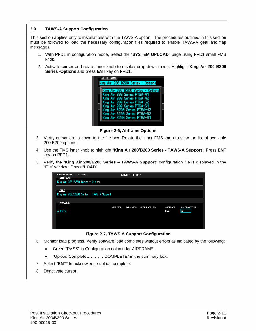
2. Activate cursor and rotate inner knob to display drop down menu. Highlight King Air 200 B200 Series -Options and press ENT key on PFD1.
Figure 2-6, Airframe Options
3. Verify cursor drops down to the file box. Rotate the inner FMS knob to view the list of available 200 B200 options.
4. Use the FMS inner knob to highlight “King Air 200/B200 Series - TAWS-A Support”. Press ENT key on PFD1.
5. Verify the “King Air 200/B200 Series – TAWS-A Support” configuration file is displayed in the “File” window. Press “LOAD”.
Figure 2-7, TAWS-A Support Configuration
6. Monitor load progress. Verify software load completes without errors as indicated by the following:
• Green “PASS” in Configuration column for AIRFRAME.
• “Upload Complete………….COMPLETE” in the summary box.
7. Select “ENT” to acknowledge upload complete.
8. Deactivate cursor.
Page 2-12 Post Installation Checkout Procedures Revision 6 King Air 200/B200 Series 190-00915-00
2.10 TAWS-A Voice No Callout Option Configuration
This section applies only to installations with the TAWS-A option. If TAWS-A voice callouts (400, 300, 200, 100) are not desired, follow the procedures outlined in this section to load the necessary configuration files to disable TAWS-A voice callouts.
1. With PFD1 in configuration mode, Select the “SYSTEM UPLOAD” page using PFD1 small FMS knob.
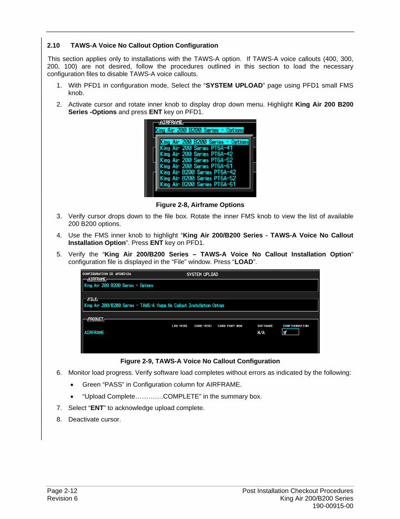
2. Activate cursor and rotate inner knob to display drop down menu. Highlight King Air 200 B200 Series -Options and press ENT key on PFD1.
Figure 2-8, Airframe Options
3. Verify cursor drops down to the file box. Rotate the inner FMS knob to view the list of available 200 B200 options.
4. Use the FMS inner knob to highlight “King Air 200/B200 Series - TAWS-A Voice No Callout Installation Option”. Press ENT key on PFD1.
5. Verify the “King Air 200/B200 Series – TAWS-A Voice No Callout Installation Option” configuration file is displayed in the “File” window. Press “LOAD”.
Figure 2-9, TAWS-A Voice No Callout Configuration
6. Monitor load progress. Verify software load completes without errors as indicated by the following:
• Green “PASS” in Configuration column for AIRFRAME.
• “Upload Complete………….COMPLETE” in the summary box.
7. Select “ENT” to acknowledge upload complete.
8. Deactivate cursor.
Post Installation Checkout Procedures Page 2-13 King Air 200/B200 Series Revision 6 190-00915-00
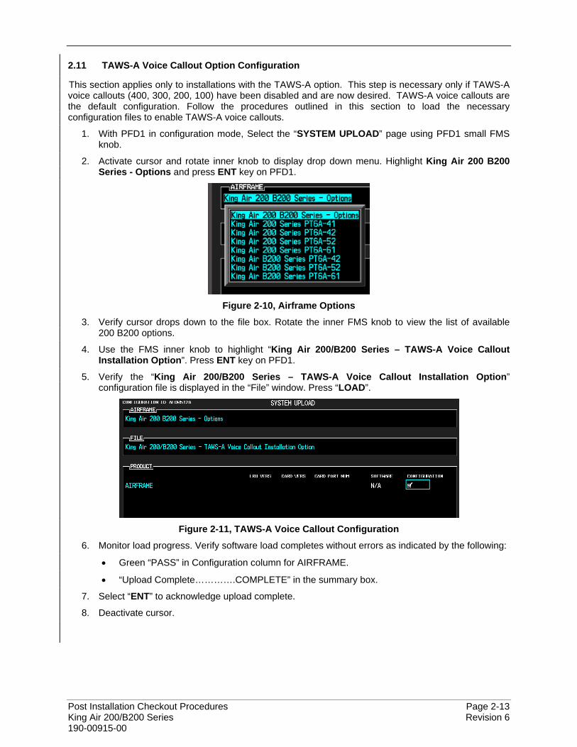
2.11 TAWS-A Voice Callout Option Configuration
This section applies only to installations with the TAWS-A option. This step is necessary only if TAWS-A voice callouts (400, 300, 200, 100) have been disabled and are now desired. TAWS-A voice callouts are the default configuration. Follow the procedures outlined in this section to load the necessary configuration files to enable TAWS-A voice callouts.
1. With PFD1 in configuration mode, Select the “SYSTEM UPLOAD” page using PFD1 small FMS knob.
2. Activate cursor and rotate inner knob to display drop down menu. Highlight King Air 200 B200 Series - Options and press ENT key on PFD1.
Figure 2-10, Airframe Options
3. Verify cursor drops down to the file box. Rotate the inner FMS knob to view the list of available 200 B200 options.
4. Use the FMS inner knob to highlight “King Air 200/B200 Series – TAWS-A Voice Callout Installation Option”. Press ENT key on PFD1.
5. Verify the “King Air 200/B200 Series – TAWS-A Voice Callout Installation Option” configuration file is displayed in the “File” window. Press “LOAD”.
Figure 2-11, TAWS-A Voice Callout Configuration
6. Monitor load progress. Verify software load completes without errors as indicated by the following:
• Green “PASS” in Configuration column for AIRFRAME.
• “Upload Complete………….COMPLETE” in the summary box.
7. Select “ENT” to acknowledge upload complete.
8. Deactivate cursor.
Page 2-14 Post Installation Checkout Procedures Revision 6 King Air 200/B200 Series 190-00915-00
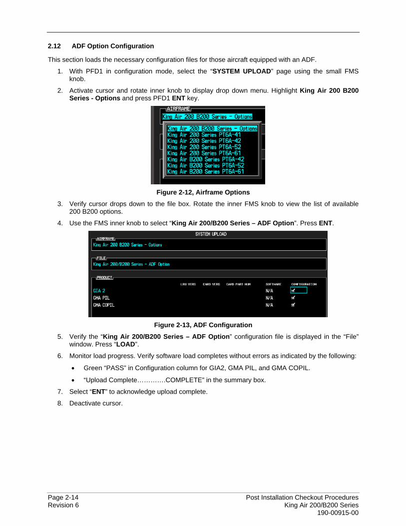
2.12 ADF Option Configuration
This section loads the necessary configuration files for those aircraft equipped with an ADF.
1. With PFD1 in configuration mode, select the “SYSTEM UPLOAD” page using the small FMS knob.
2. Activate cursor and rotate inner knob to display drop down menu. Highlight King Air 200 B200 Series - Options and press PFD1 ENT key.
Figure 2-12, Airframe Options
3. Verify cursor drops down to the file box. Rotate the inner FMS knob to view the list of available 200 B200 options.
4. Use the FMS inner knob to select “King Air 200/B200 Series – ADF Option”. Press ENT.
Figure 2-13, ADF Configuration
5. Verify the “King Air 200/B200 Series – ADF Option” configuration file is displayed in the “File” window. Press “LOAD”.
6. Monitor load progress. Verify software load completes without errors as indicated by the following:
• Green “PASS” in Configuration column for GIA2, GMA PIL, and GMA COPIL.
• “Upload Complete………….COMPLETE” in the summary box.
7. Select “ENT” to acknowledge upload complete.
8. Deactivate cursor.
Post Installation Checkout Procedures Page 2-15 King Air 200/B200 Series Revision 6 190-00915-00
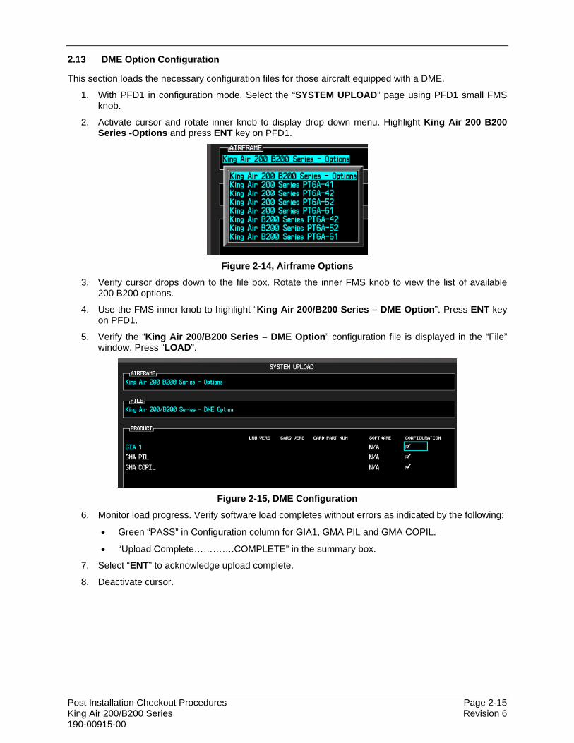
2.13 DME Option Configuration
This section loads the necessary configuration files for those aircraft equipped with a DME.
1. With PFD1 in configuration mode, Select the “SYSTEM UPLOAD” page using PFD1 small FMS knob.
2. Activate cursor and rotate inner knob to display drop down menu. Highlight King Air 200 B200 Series -Options and press ENT key on PFD1.
Figure 2-14, Airframe Options
3. Verify cursor drops down to the file box. Rotate the inner FMS knob to view the list of available 200 B200 options.
4. Use the FMS inner knob to highlight “King Air 200/B200 Series – DME Option”. Press ENT key on PFD1.
5. Verify the “King Air 200/B200 Series – DME Option” configuration file is displayed in the “File” window. Press “LOAD”.
Figure 2-15, DME Configuration
6. Monitor load progress. Verify software load completes without errors as indicated by the following:
• Green “PASS” in Configuration column for GIA1, GMA PIL and GMA COPIL.
• “Upload Complete………….COMPLETE” in the summary box.
7. Select “ENT” to acknowledge upload complete.
8. Deactivate cursor.
Page 2-16 Post Installation Checkout Procedures Revision 6 King Air 200/B200 Series 190-00915-00
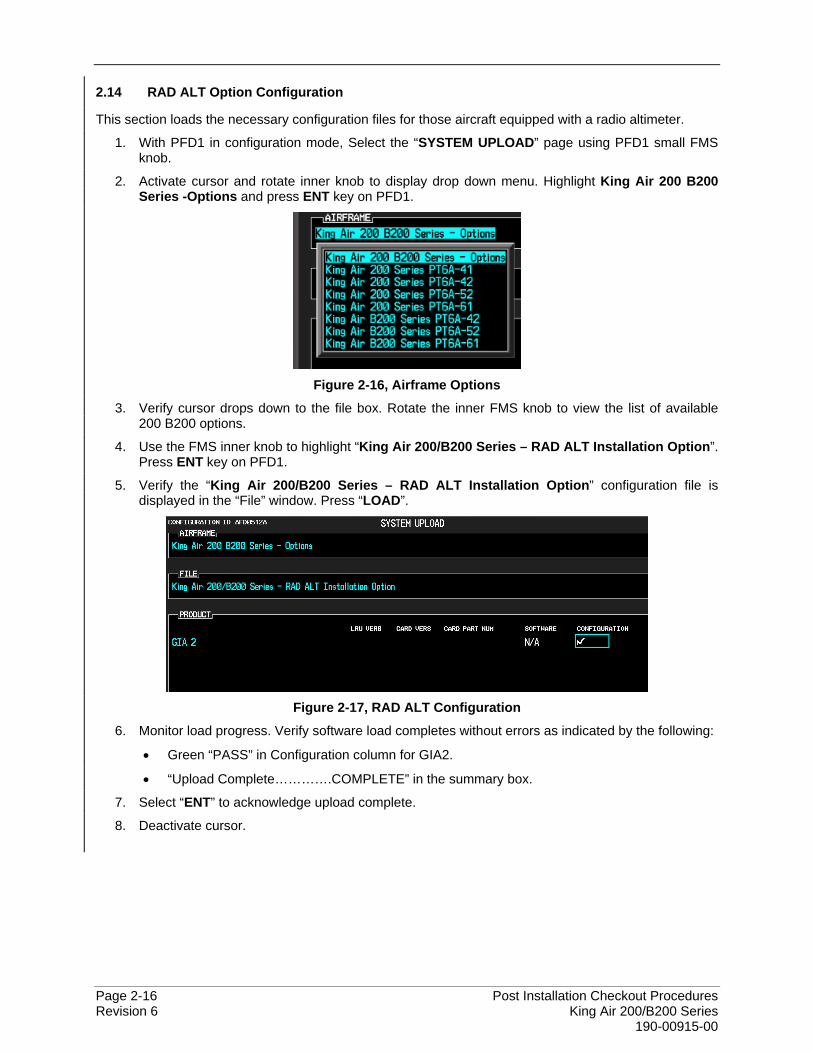
2.14 RAD ALT Option Configuration
This section loads the necessary configuration files for those aircraft equipped with a radio altimeter.
1. With PFD1 in configuration mode, Select the “SYSTEM UPLOAD” page using PFD1 small FMS knob.
2. Activate cursor and rotate inner knob to display drop down menu. Highlight King Air 200 B200 Series -Options and press ENT key on PFD1.
Figure 2-16, Airframe Options
3. Verify cursor drops down to the file box. Rotate the inner FMS knob to view the list of available 200 B200 options.
4. Use the FMS inner knob to highlight “King Air 200/B200 Series – RAD ALT Installation Option”. Press ENT key on PFD1.
5. Verify the “King Air 200/B200 Series – RAD ALT Installation Option” configuration file is displayed in the “File” window. Press “LOAD”.
Figure 2-17, RAD ALT Configuration
6. Monitor load progress. Verify software load completes without errors as indicated by the following:
• Green “PASS” in Configuration column for GIA2.
• “Upload Complete………….COMPLETE” in the summary box.
7. Select “ENT” to acknowledge upload complete.
8. Deactivate cursor.
Post Installation Checkout Procedures Page 2-17 King Air 200/B200 Series Revision 6 190-00915-00
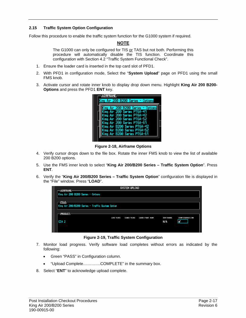
2.15 Traffic System Option Configuration
Follow this procedure to enable the traffic system function for the G1000 system if required.
NOTE The G1000 can only be configured for TIS or TAS but not both. Performing this procedure will automatically disable the TIS function. Coordinate this configuration with Section 4.2 “Traffic System Functional Check”.
1. Ensure the loader card is inserted in the top card slot of PFD1.
2. With PFD1 in configuration mode, Select the “System Upload” page on PFD1 using the small FMS knob.
3. Activate cursor and rotate inner knob to display drop down menu. Highlight King Air 200 B200-Options and press the PFD1 ENT key.
Figure 2-18, Airframe Options
4. Verify cursor drops down to the file box. Rotate the inner FMS knob to view the list of available 200 B200 options.
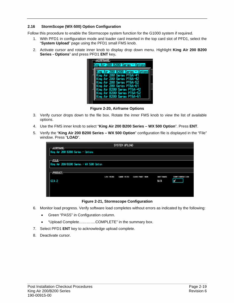
5. Use the FMS inner knob to select “King Air 200/B200 Series – Traffic System Option”. Press ENT.
6. Verify the “King Air 200/B200 Series – Traffic System Option” configuration file is displayed in the “File” window. Press “LOAD”.
Figure 2-19, Traffic System Configuration
7. Monitor load progress. Verify software load completes without errors as indicated by the following:
• Green “PASS” in Configuration column.
• “Upload Complete………….COMPLETE” in the summary box.
8. Select “ENT” to acknowledge upload complete.

Page 2-18 Post Installation Checkout Procedures Revision 6 King Air 200/B200 Series 190-00915-00
2.15.1 Configuration of Navigation Map for Traffic System
1. With the MFD in normal mode, use the GCU FMS knob to select the Navigation Map page then press GCU MENU key to display the PAGE MENU.
2. Turn the small right knob to select or verify selected ‘Map Setup’ and press the ENT key and verify TRAFFIC is selected ON.
3. Verify the flashing cursor highlights the GROUP field.
4. Turn the GCU small FMS knob to select Traffic and press ENT on GCU.
5. If not already selected, use the GCU FMS knob to make the following selections:
• TRAFFIC MODE – ALL TRAFFIC
• TRAFFIC SMBL – 300NM
• TRAFFIC LBL – 300NM
6. Return to the Map Page by pressing the GCU FMS knob or momentarily pressing and holding the CLR key. Deactivate cursor.
Post Installation Checkout Procedures Page 2-19 King Air 200/B200 Series Revision 6 190-00915-00
2.16 StormScope (WX-500) Option Configuration
Follow this procedure to enable the Stormscope system function for the G1000 system if required. 1. With PFD1 in configuration mode and loader card inserted in the top card slot of PFD1, select the
“System Upload” page using the PFD1 small FMS knob.
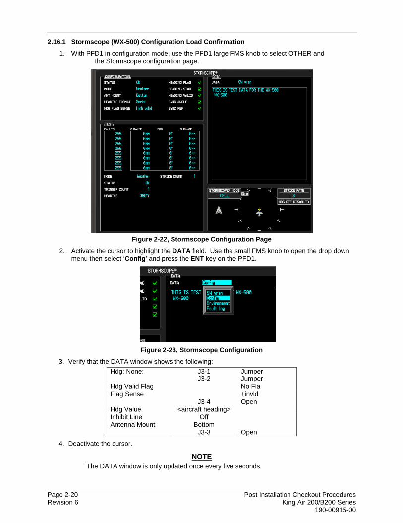
2. Activate cursor and rotate inner knob to display drop down menu. Highlight King Air 200 B200 Series - Options” and press PFD1 ENT key.
Figure 2-20, Airframe Options
3. Verify cursor drops down to the file box. Rotate the inner FMS knob to view the list of available options.
4. Use the FMS inner knob to select “King Air 200 B200 Series – WX 500 Option”. Press ENT.
5. Verify the “King Air 200 B200 Series – WX 500 Option” configuration file is displayed in the “File” window. Press “LOAD”.
Figure 2-21, Stormscope Configuration
6. Monitor load progress. Verify software load completes without errors as indicated by the following:
• Green “PASS” in Configuration column.
• “Upload Complete………….COMPLETE” in the summary box.
7. Select PFD1 ENT key to acknowledge upload complete.
8. Deactivate cursor.
Page 2-20 Post Installation Checkout Procedures Revision 6 King Air 200/B200 Series 190-00915-00
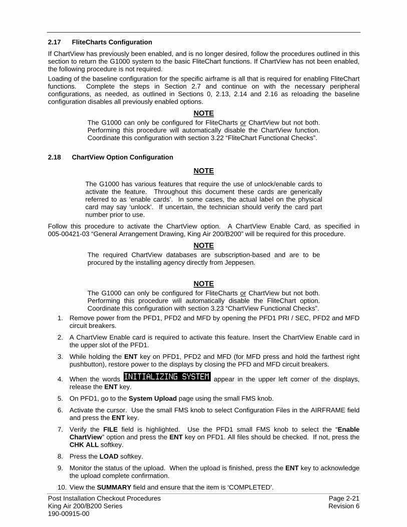
2.16.1 Stormscope (WX-500) Configuration Load Confirmation
1. With PFD1 in configuration mode, use the PFD1 large FMS knob to select OTHER and the Stormscope configuration page.
Figure 2-22, Stormscope Configuration Page
2. Activate the cursor to highlight the DATA field. Use the small FMS knob to open the drop down menu then select ‘Config’ and press the ENT key on the PFD1.
Figure 2-23, Stormscope Configuration
3. Verify that the DATA window shows the following: Hdg: None: J3-1 Jumper J3-2 Jumper Hdg Valid Flag No Fla Flag Sense +invld J3-4 Open Hdg Value <aircraft heading> Inhibit Line Off Antenna Mount Bottom J3-3 Open
4. Deactivate the cursor.
NOTE The DATA window is only updated once every five seconds.
Post Installation Checkout Procedures Page 2-21 King Air 200/B200 Series Revision 6 190-00915-00
2.17 FliteCharts Configuration
If ChartView has previously been enabled, and is no longer desired, follow the procedures outlined in this section to return the G1000 system to the basic FliteChart functions. If ChartView has not been enabled, the following procedure is not required. Loading of the baseline configuration for the specific airframe is all that is required for enabling FliteChart functions. Complete the steps in Section 2.7 and continue on with the necessary peripheral configurations, as needed, as outlined in Sections 0, 2.13, 2.14 and 2.16 as reloading the baseline configuration disables all previously enabled options.
NOTE The G1000 can only be configured for FliteCharts or ChartView but not both. Performing this procedure will automatically disable the ChartView function. Coordinate this configuration with section 3.22 “FliteChart Functional Checks”.
2.18 ChartView Option Configuration
NOTE
The G1000 has various features that require the use of unlock/enable cards to activate the feature. Throughout this document these cards are generically referred to as ‘enable cards’. In some cases, the actual label on the physical card may say ‘unlock’. If uncertain, the technician should verify the card part number prior to use.
Follow this procedure to activate the ChartView option. A ChartView Enable Card, as specified in 005-00421-03 “General Arrangement Drawing, King Air 200/B200” will be required for this procedure.
NOTE The required ChartView databases are subscription-based and are to be procured by the installing agency directly from Jeppesen.
NOTE The G1000 can only be configured for FliteCharts or ChartView but not both. Performing this procedure will automatically disable the FliteChart option. Coordinate this configuration with section 3.23 “ChartView Functional Checks”.
1. Remove power from the PFD1, PFD2 and MFD by opening the PFD1 PRI / SEC, PFD2 and MFD circuit breakers.
2. A ChartView Enable card is required to activate this feature. Insert the ChartView Enable card in the upper slot of the PFD1.
3. While holding the ENT key on PFD1, PFD2 and MFD (for MFD press and hold the farthest right pushbutton), restore power to the displays by closing the PFD and MFD circuit breakers.
4. When the words appear in the upper left corner of the displays, release the ENT key.
5. On PFD1, go to the System Upload page using the small FMS knob.
6. Activate the cursor. Use the small FMS knob to select Configuration Files in the AIRFRAME field and press the ENT key.
7. Verify the FILE field is highlighted. Use the PFD1 small FMS knob to select the “Enable ChartView” option and press the ENT key on PFD1. All files should be checked. If not, press the CHK ALL softkey.
8. Press the LOAD softkey.
9. Monitor the status of the upload. When the upload is finished, press the ENT key to acknowledge the upload complete confirmation.
10. View the SUMMARY field and ensure that the item is ‘COMPLETED’.
Page 2-22 Post Installation Checkout Procedures Revision 6 King Air 200/B200 Series 190-00915-00
11. De-activate the cursor.
12. Power down the system and remove the ChartView Enable card from PFD1.
2.19 TAWS-B Enable
Follow this procedure to enable the TAWS Class B function. A TAWS-B Enable Card, as specified on General Arrangement Drawing 005-00421-03, will be required for this procedure.
NOTE
The G1000 has various features that require the use of unlock/enable cards to activate the feature. Throughout this document these cards are generically referred to as ‘enable cards’. In some cases, the actual label on the physical card may say ‘unlock’. If uncertain, the technician should verify the card part number prior to use.
1. If not applied, apply power to the G1000 system.
2. Remove power from PFD1, PFD2 and MFD by opening the PFD1 PRI/SEC, PFD2 and MFD circuit breakers.
3. Insert the TAWS B Enable Card in the upper slot of PFD1.
4. While holding the ENT key on the PFD1, PFD2 and MFD (for MFD press and hold the farthest right pushbutton), restore power to the displays.
5. When the words appear in the upper left corner of the displays, release the ENT key.
6. On PFD1, go to the System Upload page using the small PFD1 FMS knob.
7. Activate the cursor. Use the small PFD1 FMS knob to select CONFIGURATION FILES in the AIRFRAME field and press the PFD1 ENT key.
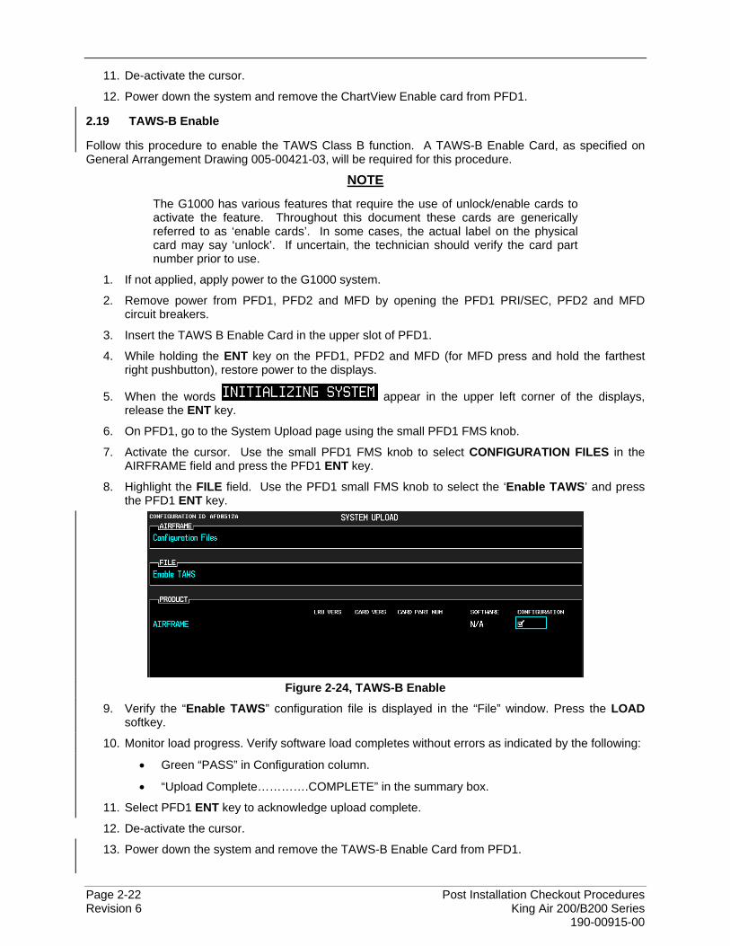
8. Highlight the FILE field. Use the PFD1 small FMS knob to select the ‘Enable TAWS’ and press the PFD1 ENT key.
Figure 2-24, TAWS-B Enable
9. Verify the “Enable TAWS” configuration file is displayed in the “File” window. Press the LOAD softkey.
10. Monitor load progress. Verify software load completes without errors as indicated by the following:
• Green “PASS” in Configuration column.
• “Upload Complete………….COMPLETE” in the summary box.
11. Select PFD1 ENT key to acknowledge upload complete.
12. De-activate the cursor.
13. Power down the system and remove the TAWS-B Enable Card from PFD1.
Post Installation Checkout Procedures Page 2-23 King Air 200/B200 Series Revision 6 190-00915-00
2.20 TAWS-A Enable
Follow this procedure to enable the TAWS Class A function. A TAWS-A Enable Card, as specified on General Arrangement Drawing 005-00421-03, will be required for this procedure.
NOTE
The G1000 has various features that require the use of unlock/enable cards to activate the feature. Throughout this document these cards are generically referred to as ‘enable cards’. In some cases, the actual label on the physical card may say ‘unlock’. If uncertain, the technician should verify the card part number prior to use. Ensure that the TAWS-A Support Configuration has been loaded per Section 2.9. Ensure that the RAD ALT Option Configuration has been loaded per Section 2.14.
1. If not applied, apply power to the G1000 system.
2. Remove power from PFD1, PFD2 and MFD by opening the PFD1 PRI/SEC, PFD2 and MFD circuit breakers.
3. Insert the TAWS-A Enable Card in the upper slot of PFD1.
4. While holding the ENT key on the PFD1, PFD2 and MFD (for MFD press and hold the farthest right pushbutton), restore power to the displays.
5. When the words appear in the upper left corner of the displays, release the ENT key.
6. On PFD1, go to the System Upload page using the small PFD1 FMS knob.
7. Activate the cursor. Use the small PFD1 FMS knob to select CONFIGURATION FILES in the AIRFRAME field and press the PFD1 ENT key.
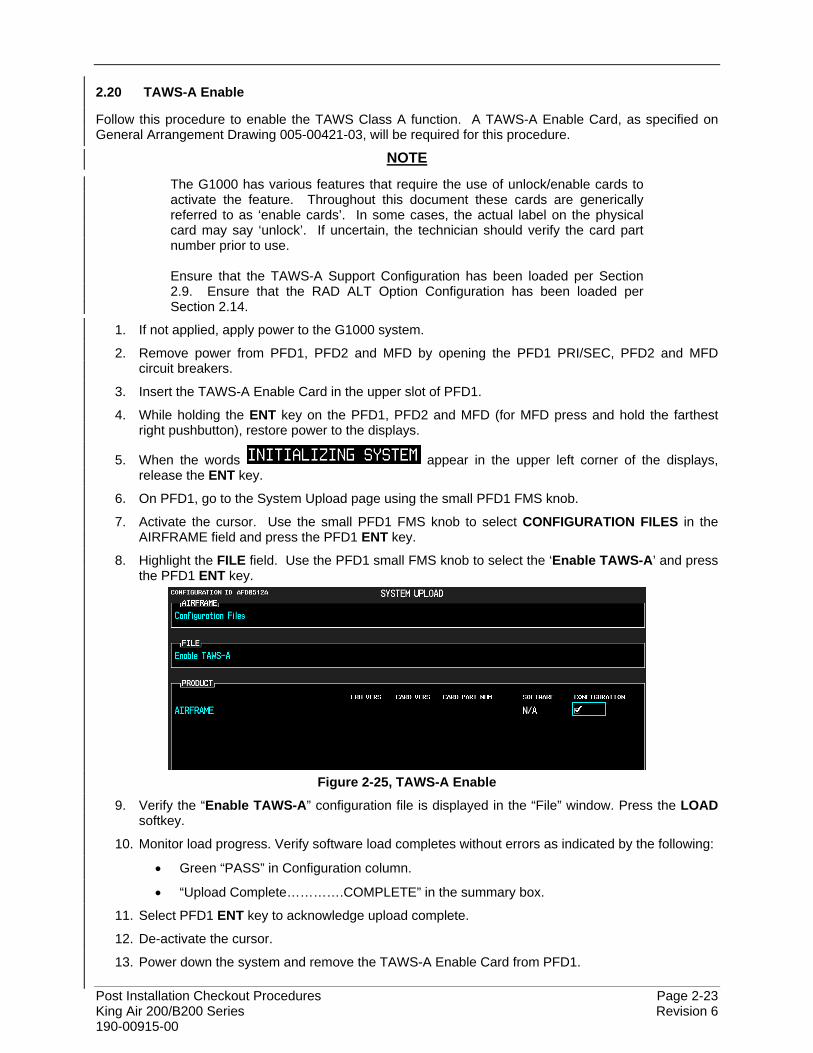
8. Highlight the FILE field. Use the PFD1 small FMS knob to select the ‘Enable TAWS-A’ and press the PFD1 ENT key.
Figure 2-25, TAWS-A Enable
9. Verify the “Enable TAWS-A” configuration file is displayed in the “File” window. Press the LOAD softkey.
10. Monitor load progress. Verify software load completes without errors as indicated by the following:
• Green “PASS” in Configuration column.
• “Upload Complete………….COMPLETE” in the summary box.
11. Select PFD1 ENT key to acknowledge upload complete.
12. De-activate the cursor.
13. Power down the system and remove the TAWS-A Enable Card from PFD1.
Page 2-24 Post Installation Checkout Procedures Revision 6 King Air 200/B200 Series 190-00915-00
2.21 Terrain/Obstacle Database Loading
1. Open PFD1, PFD2 and MFD circuit breakers.
2. Insert an SD card containing current Terrain/Obstacle database cards into the lower slots of PFDs and MFD. Refer to the General Arrangement drawing 005-00421-03 for correct card part numbers.
3. Close PFD1, PFD2 and MFD circuit breakers.
2.22 SVS/Pathways Enable
Follow this procedure to enable the Synthetic Vision option. A GDU1XXX SVS Enable Card, as specified on General Arrangement Drawing 005-00421-03, will be required for this procedure.
NOTE
The G1000 has various features that require the use of unlock/enable cards to activate the feature. Throughout this document these cards are generically referred to as ‘enable cards’. In some cases, the actual label on the physical card may say ‘unlock’. If uncertain, the technician should verify the card part number prior to use.
NOTE The Garmin Synthetic Vision and Pathways feature requires 9 arc-second high resolution terrain databases to function. Each G1000 display must be equipped with the Terrain/Obstacle/SafeTaxi database card installed in the lower slot.
NOTE When the SVS/Pathways option is enabled for the first time the G1000 writes its unique system ID to the physical card and locks the files to this unique ID. This prevents the SVS/Pathways unlock card from ever being used to activate the SVS/Pathway feature in other G1000 systems. The unlock card is tied to the specific aircraft in which it was used for the first time. This card MUST be kept with the aircraft for situations where SVS/Pathways must be re-activated.
1. If not applied, apply power to the G1000 system.
2. Remove power from PFD1, PFD2 and MFD by opening the PFD1 PRI/SEC, PFD2 and MFD circuit breakers.
3. Insert the SVS Enable card in the upper slot of PFD1.
4. While holding the ENT key on the PFD1, PFD2 and MFD (for MFD press and hold the farthest right pushbutton), restore power to the displays.
5. When the words appear in the upper left corner of the displays, release the ENT key.
6. On PFD1, go to the System Upload page using the small PFD1 FMS knob.
7. Activate the cursor. Use the small PFD1 FMS knob to select CONFIGURATION FILES in the AIRFRAME field and press the PFD1 ENT key.
8. Highlight the FILE field. Use the PFD1 small FMS knob to select the ‘Enable SVS Dual PFD’ option and press the PFD1 ENT key. Once the option is selected, the configuration files in the PRODUCT field will be displayed. All files should be checked. If not, press the CHK ALL softkey.
9. Press the LOAD softkey.
10. Monitor the status of the upload. When the upload is finished, press the PFD1 ENT key to acknowledge the upload complete confirmation.
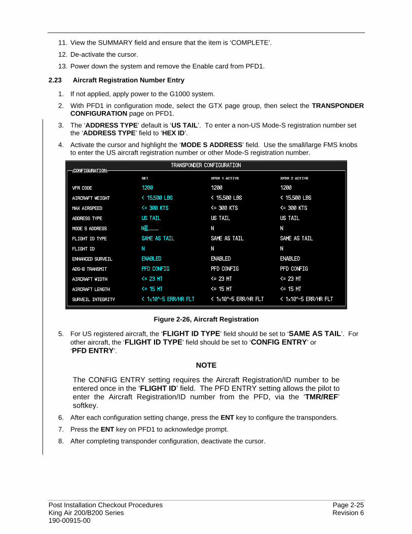
Post Installation Checkout Procedures Page 2-25 King Air 200/B200 Series Revision 6 190-00915-00
11. View the SUMMARY field and ensure that the item is ‘COMPLETE’.
12. De-activate the cursor.
13. Power down the system and remove the Enable card from PFD1.
2.23 Aircraft Registration Number Entry
1. If not applied, apply power to the G1000 system.
2. With PFD1 in configuration mode, select the GTX page group, then select the TRANSPONDER CONFIGURATION page on PFD1.
3. The ‘ADDRESS TYPE’ default is ‘US TAIL’. To enter a non-US Mode-S registration number set the ‘ADDRESS TYPE’ field to ‘HEX ID’.
4. Activate the cursor and highlight the ‘MODE S ADDRESS’ field. Use the small/large FMS knobs to enter the US aircraft registration number or other Mode-S registration number.
Figure 2-26, Aircraft Registration
5. For US registered aircraft, the ‘FLIGHT ID TYPE’ field should be set to ‘SAME AS TAIL’. For other aircraft, the ‘FLIGHT ID TYPE’ field should be set to ‘CONFIG ENTRY’ or ‘PFD ENTRY’.
NOTE
The CONFIG ENTRY setting requires the Aircraft Registration/ID number to be entered once in the ‘FLIGHT ID’ field. The PFD ENTRY setting allows the pilot to enter the Aircraft Registration/ID number from the PFD, via the ‘TMR/REF’ softkey.
6. After each configuration setting change, press the ENT key to configure the transponders.
7. Press the ENT key on PFD1 to acknowledge prompt.
8. After completing transponder configuration, deactivate the cursor.
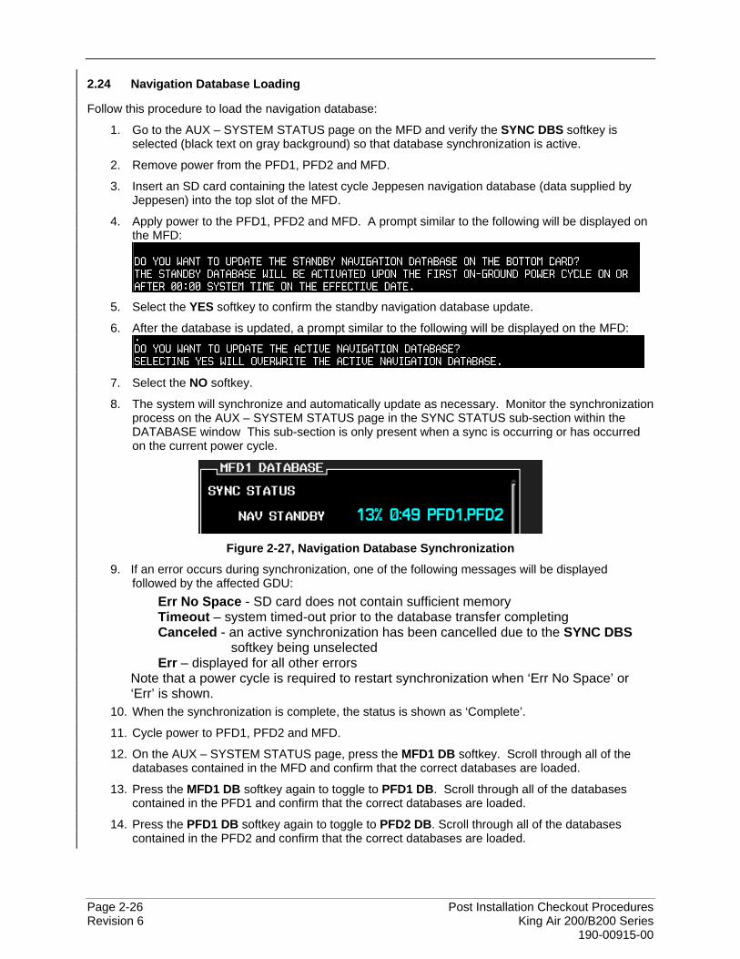
Page 2-26 Post Installation Checkout Procedures Revision 6 King Air 200/B200 Series 190-00915-00
2.24 Navigation Database Loading
Follow this procedure to load the navigation database:
1. Go to the AUX – SYSTEM STATUS page on the MFD and verify the SYNC DBS softkey is selected (black text on gray background) so that database synchronization is active.
2. Remove power from the PFD1, PFD2 and MFD.
3. Insert an SD card containing the latest cycle Jeppesen navigation database (data supplied by Jeppesen) into the top slot of the MFD.
4. Apply power to the PFD1, PFD2 and MFD. A prompt similar to the following will be displayed on the MFD:
5. Select the YES softkey to confirm the standby navigation database update.
6. After the database is updated, a prompt similar to the following will be displayed on the MFD:
7. Select the NO softkey.
8. The system will synchronize and automatically update as necessary. Monitor the synchronization process on the AUX – SYSTEM STATUS page in the SYNC STATUS sub-section within the DATABASE window This sub-section is only present when a sync is occurring or has occurred on the current power cycle.
Figure 2-27, Navigation Database Synchronization
9. If an error occurs during synchronization, one of the following messages will be displayed followed by the affected GDU:
Err No Space - SD card does not contain sufficient memory Timeout – system timed-out prior to the database transfer completing Canceled - an active synchronization has been cancelled due to the SYNC DBS
softkey being unselected Err – displayed for all other errors
Note that a power cycle is required to restart synchronization when ‘Err No Space’ or ‘Err’ is shown.
10. When the synchronization is complete, the status is shown as ‘Complete’.
11. Cycle power to PFD1, PFD2 and MFD.
12. On the AUX – SYSTEM STATUS page, press the MFD1 DB softkey. Scroll through all of the databases contained in the MFD and confirm that the correct databases are loaded.
13. Press the MFD1 DB softkey again to toggle to PFD1 DB. Scroll through all of the databases contained in the PFD1 and confirm that the correct databases are loaded.
14. Press the PFD1 DB softkey again to toggle to PFD2 DB. Scroll through all of the databases contained in the PFD2 and confirm that the correct databases are loaded.
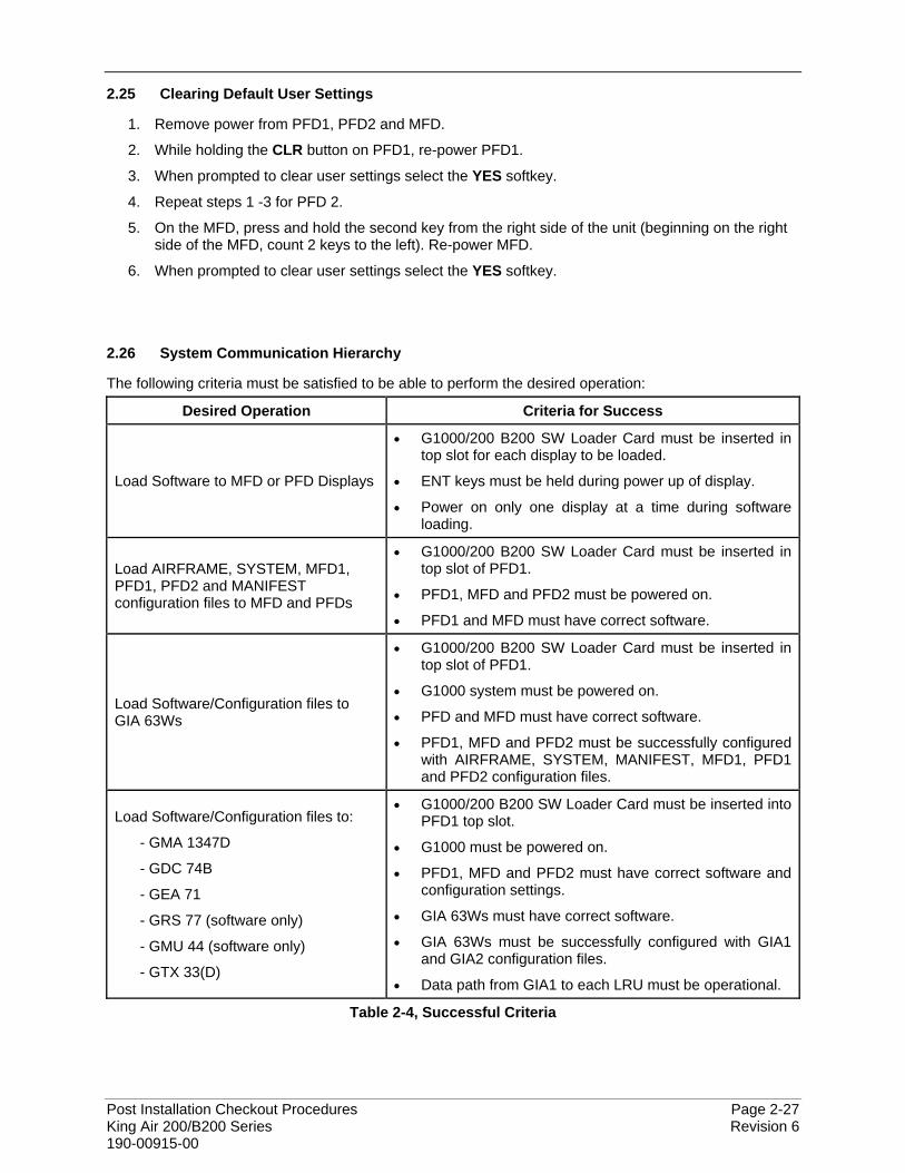
Post Installation Checkout Procedures Page 2-27 King Air 200/B200 Series Revision 6 190-00915-00
2.25 Clearing Default User Settings
1. Remove power from PFD1, PFD2 and MFD.
2. While holding the CLR button on PFD1, re-power PFD1.
3. When prompted to clear user settings select the YES softkey.
4. Repeat steps 1 -3 for PFD 2.
5. On the MFD, press and hold the second key from the right side of the unit (beginning on the right side of the MFD, count 2 keys to the left). Re-power MFD.
6. When prompted to clear user settings select the YES softkey.
2.26 System Communication Hierarchy
The following criteria must be satisfied to be able to perform the desired operation:
Desired Operation Criteria for Success
Load Software to MFD or PFD Displays
• G1000/200 B200 SW Loader Card must be inserted in top slot for each display to be loaded.
• ENT keys must be held during power up of display.
• Power on only one display at a time during software loading.
Load AIRFRAME, SYSTEM, MFD1, PFD1, PFD2 and MANIFEST configuration files to MFD and PFDs
• G1000/200 B200 SW Loader Card must be inserted in top slot of PFD1.
• PFD1, MFD and PFD2 must be powered on.
• PFD1 and MFD must have correct software.
Load Software/Configuration files to GIA 63Ws
• G1000/200 B200 SW Loader Card must be inserted in top slot of PFD1.
• G1000 system must be powered on.
• PFD and MFD must have correct software.
• PFD1, MFD and PFD2 must be successfully configured with AIRFRAME, SYSTEM, MANIFEST, MFD1, PFD1 and PFD2 configuration files.
Load Software/Configuration files to:
- GMA 1347D
- GDC 74B
- GEA 71
- GRS 77 (software only)
- GMU 44 (software only)
- GTX 33(D)
• G1000/200 B200 SW Loader Card must be inserted into PFD1 top slot.
• G1000 must be powered on.
• PFD1, MFD and PFD2 must have correct software and configuration settings.
• GIA 63Ws must have correct software.
• GIA 63Ws must be successfully configured with GIA1 and GIA2 configuration files.
• Data path from GIA1 to each LRU must be operational.
Table 2-4, Successful Criteria
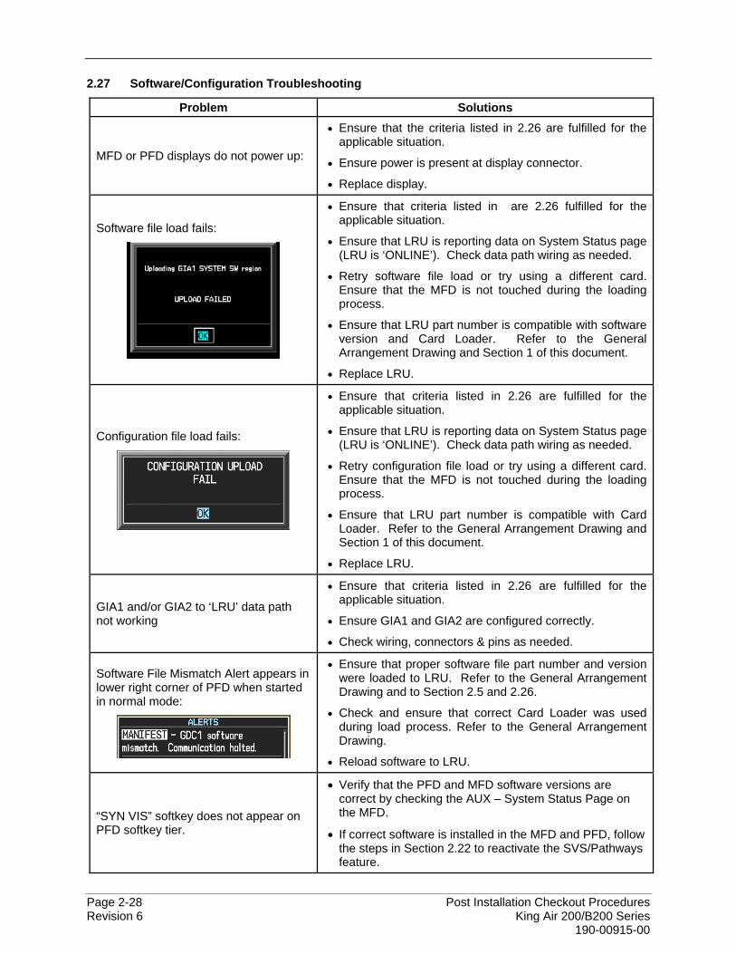
Page 2-28 Post Installation Checkout Procedures Revision 6 King Air 200/B200 Series 190-00915-00
2.27 Software/Configuration Troubleshooting
Problem Solutions
MFD or PFD displays do not power up:
• Ensure that the criteria listed in 2.26 are fulfilled for the applicable situation.
• Ensure power is present at display connector.
• Replace display.
Software file load fails:
• Ensure that criteria listed in are 2.26 fulfilled for the applicable situation.
• Ensure that LRU is reporting data on System Status page (LRU is ‘ONLINE’). Check data path wiring as needed.
• Retry software file load or try using a different card. Ensure that the MFD is not touched during the loading process.
• Ensure that LRU part number is compatible with software version and Card Loader. Refer to the General Arrangement Drawing and Section 1 of this document.
• Replace LRU.
Configuration file load fails:
• Ensure that criteria listed in 2.26 are fulfilled for the applicable situation.
• Ensure that LRU is reporting data on System Status page (LRU is ‘ONLINE’). Check data path wiring as needed.
• Retry configuration file load or try using a different card. Ensure that the MFD is not touched during the loading process.
• Ensure that LRU part number is compatible with Card Loader. Refer to the General Arrangement Drawing and Section 1 of this document.
• Replace LRU.
GIA1 and/or GIA2 to ‘LRU’ data path not working
• Ensure that criteria listed in 2.26 are fulfilled for the applicable situation.
• Ensure GIA1 and GIA2 are configured correctly.
• Check wiring, connectors & pins as needed.
Software File Mismatch Alert appears in lower right corner of PFD when started in normal mode:
• Ensure that proper software file part number and version were loaded to LRU. Refer to the General Arrangement Drawing and to Section 2.5 and 2.26.
• Check and ensure that correct Card Loader was used during load process. Refer to the General Arrangement Drawing.
• Reload software to LRU.
“SYN VIS” softkey does not appear on PFD softkey tier.
• Verify that the PFD and MFD software versions are correct by checking the AUX – System Status Page on the MFD.
• If correct software is installed in the MFD and PFD, follow the steps in Section 2.22 to reactivate the SVS/Pathways feature.

Post Installation Checkout Procedures Page 2-29 King Air 200/B200 Series Revision 6 190-00915-00
Problem Solutions
3D terrain presentation does not appear on PFD.
• Verify that P/N 010-00330-43 terrain datacards are installed in the lower slot of the PFD and MFD.
• Verify that the G1000 AHRS, and heading data are valid on the PFD. Verify that a valid GPS 3D position solution is being received.
• If a terrain database update has just been performed, allow the system time to initialize and verify the data. When the databases have been verified, the current database cycle and version are reported on the MFD AUX – System Status page.
Table 2-5, Troubleshooting

Page 2-30 Post Installation Checkout Procedures Revision 6 King Air 200/B200 Series 190-00915-00
This page intentionally left blank
Post Installation Checkout Procedures Page 3-1 King Air 200/B200 Series Revision 6 190-00915-00
3 G1000 INITIAL SYSTEM TESTING
3.1 Aircraft Systems Checks
This section outlines instructions for testing the various aircraft systems that may have been, or were affected by the G1000/GFC700 system installation. No test set forth in this section should be used in lieu of the maintenance procedures contained within the Beechcraft Super King Air Series 200/B200 maintenance manuals and are to be used in a supplemental manner only.
3.2 Electrical Power Distribution Testing
NOTE Throughout this test, verify only the appropriate system(s) are affected by the circuit breaker (CB) being opened. Between each step, allow enough time for each system to return to normal following CB closure.
1. Apply external power. Turn BATT and AVIONICS MASTER switches to ON position. Verify all circuit breakers are closed. Observe PFD1, PFD2 and MFD displays and verify all displays are powered and in normal format. Select, or verify selected, on-side sensors for PFD1 and PFD2.
2. Open PFD1 PRI CB. Verify PFD1 remains powered and no other changes occur to any G1000 or G1000 interfaced system.
3. Open PFD1 SEC CB. Verify PFD1 goes blank. 4. Close PFD1 PRI CB. Verify PFD1 is powered. Close PFD1 SEC CB. 5. Open PFD2 CB. Verify PFD2 is not powered. 6. Close PFD2 CB. Verify PFD2 is powered 7. Open GIA1 PRI CB. Verify GIA1 remains powered by observing the absence of red Xs or alert
messages and no other changes occur to any G1000 or G1000 interfaced system. 8. Open GIA1 SEC CB. Verify GIA1 is not powered by observing red Xs and/or alert messages. 9. Close GIA 1 PRI CB. Verify GIA1 is powered by observing the absence of red Xs or alert
messages and no other changes occur to any G1000 or G1000 interfaced system. Close GIA 1 SEC CB.
10. Open GIA2 CB. Verify GIA2 is not powered by observing red Xs and/or alert messages. 11. Close GIA 2 CB. Verify GIA2 is powered by observing the absence of red Xs or alert messages
and no other changes occur to any G1000 or G1000 interfaced system. 12. Open AHRS1 PRI CB. Verify AHRS1 remains powered and no other changes occur to any G1000
or G1000 interfaced system. 13. Open AHRS1 SEC CB. Verify AHRS1 is not powered by observing red Xs are displayed for
AHRS1 attitude information. 14. Close AHRS1 PRI CB. Verify AHRS1 is powered by observing valid AHRS1 attitude information.
Close AHRS1 SEC CB. 15. Open AHRS2 CB. Verify AHRS2 is not powered by observing red Xs are displayed for AHRS2
attitude information. 16. Close AHRS2. Verify AHRS2 is powered by observing valid AHRS2 attitude information. 17. Open ADC1 PRI CB. Verify ADC1 remains powered by observing valid ADC1 air data information
absence of red Xs or alert messages and no other changes occur to any G1000 or G1000 interfaced system.
18. Open ADC1 SEC CB. Verify ADC1 is not powered by observing red Xs are displayed for ADC1 air data information.
19. Close ADC1 PRI CB. Verify ADC1 is powered by observing valid ADC1 air data information. Close ADC1 SEC CB.
20. Open ADC2 CB. Verify ADC2 is not powered by observing red Xs are displayed for ADC2 air data information.
21. Close ADC2 CB. Verify ADC2 is powered by observing valid ADC2 air data information
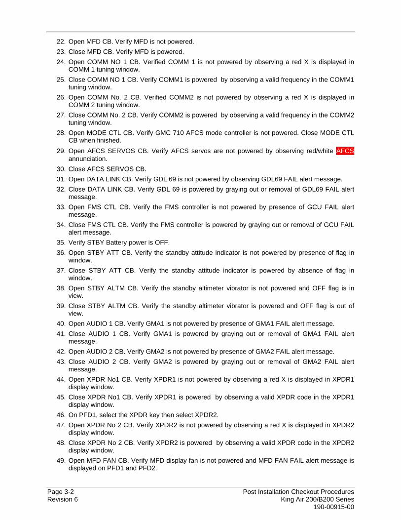
Page 3-2 Post Installation Checkout Procedures Revision 6 King Air 200/B200 Series 190-00915-00
22. Open MFD CB. Verify MFD is not powered. 23. Close MFD CB. Verify MFD is powered. 24. Open COMM NO 1 CB. Verified COMM 1 is not powered by observing a red X is displayed in
COMM 1 tuning window. 25. Close COMM NO 1 CB. Verify COMM1 is powered by observing a valid frequency in the COMM1
tuning window. 26. Open COMM No. 2 CB. Verified COMM2 is not powered by observing a red X is displayed in
COMM 2 tuning window. 27. Close COMM No. 2 CB. Verify COMM2 is powered by observing a valid frequency in the COMM2
tuning window. 28. Open MODE CTL CB. Verify GMC 710 AFCS mode controller is not powered. Close MODE CTL
CB when finished. 29. Open AFCS SERVOS CB. Verify AFCS servos are not powered by observing red/white AFCS
annunciation. 30. Close AFCS SERVOS CB. 31. Open DATA LINK CB. Verify GDL 69 is not powered by observing GDL69 FAIL alert message. 32. Close DATA LINK CB. Verify GDL 69 is powered by graying out or removal of GDL69 FAIL alert
message. 33. Open FMS CTL CB. Verify the FMS controller is not powered by presence of GCU FAIL alert
message. 34. Close FMS CTL CB. Verify the FMS controller is powered by graying out or removal of GCU FAIL
alert message. 35. Verify STBY Battery power is OFF. 36. Open STBY ATT CB. Verify the standby attitude indicator is not powered by presence of flag in
window. 37. Close STBY ATT CB. Verify the standby attitude indicator is powered by absence of flag in
window. 38. Open STBY ALTM CB. Verify the standby altimeter vibrator is not powered and OFF flag is in
view. 39. Close STBY ALTM CB. Verify the standby altimeter vibrator is powered and OFF flag is out of
view. 40. Open AUDIO 1 CB. Verify GMA1 is not powered by presence of GMA1 FAIL alert message. 41. Close AUDIO 1 CB. Verify GMA1 is powered by graying out or removal of GMA1 FAIL alert
message. 42. Open AUDIO 2 CB. Verify GMA2 is not powered by presence of GMA2 FAIL alert message. 43. Close AUDIO 2 CB. Verify GMA2 is powered by graying out or removal of GMA2 FAIL alert
message. 44. Open XPDR No1 CB. Verify XPDR1 is not powered by observing a red X is displayed in XPDR1
display window. 45. Close XPDR No1 CB. Verify XPDR1 is powered by observing a valid XPDR code in the XPDR1
display window. 46. On PFD1, select the XPDR key then select XPDR2. 47. Open XPDR No 2 CB. Verify XPDR2 is not powered by observing a red X is displayed in XPDR2
display window. 48. Close XPDR No 2 CB. Verify XPDR2 is powered by observing a valid XPDR code in the XPDR2
display window. 49. Open MFD FAN CB. Verify MFD display fan is not powered and MFD FAN FAIL alert message is
displayed on PFD1 and PFD2.
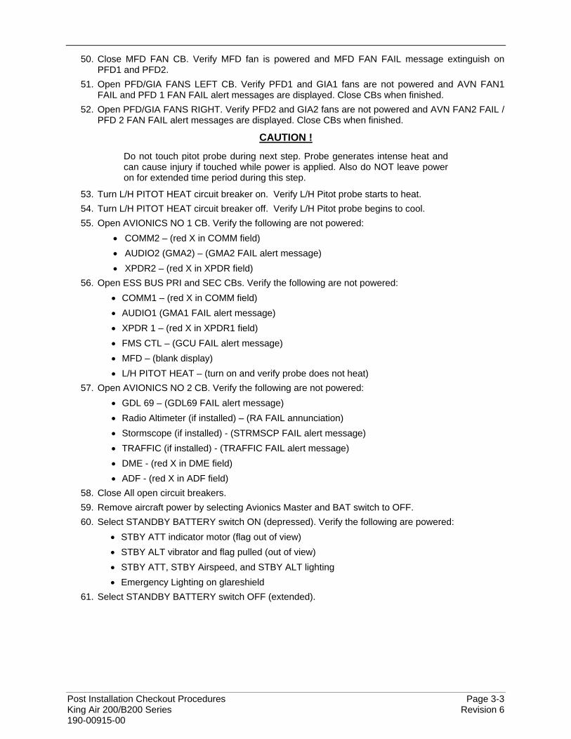
Post Installation Checkout Procedures Page 3-3 King Air 200/B200 Series Revision 6 190-00915-00
50. Close MFD FAN CB. Verify MFD fan is powered and MFD FAN FAIL message extinguish on PFD1 and PFD2.
51. Open PFD/GIA FANS LEFT CB. Verify PFD1 and GIA1 fans are not powered and AVN FAN1 FAIL and PFD 1 FAN FAIL alert messages are displayed. Close CBs when finished.
52. Open PFD/GIA FANS RIGHT. Verify PFD2 and GIA2 fans are not powered and AVN FAN2 FAIL / PFD 2 FAN FAIL alert messages are displayed. Close CBs when finished.
CAUTION !
Do not touch pitot probe during next step. Probe generates intense heat and can cause injury if touched while power is applied. Also do NOT leave power on for extended time period during this step.
53. Turn L/H PITOT HEAT circuit breaker on. Verify L/H Pitot probe starts to heat. 54. Turn L/H PITOT HEAT circuit breaker off. Verify L/H Pitot probe begins to cool. 55. Open AVIONICS NO 1 CB. Verify the following are not powered:
• COMM2 – (red X in COMM field) • AUDIO2 (GMA2) – (GMA2 FAIL alert message) • XPDR2 – (red X in XPDR field)
56. Open ESS BUS PRI and SEC CBs. Verify the following are not powered: • COMM1 – (red X in COMM field) • AUDIO1 (GMA1 FAIL alert message) • XPDR 1 – (red X in XPDR1 field) • FMS CTL – (GCU FAIL alert message) • MFD – (blank display) • L/H PITOT HEAT – (turn on and verify probe does not heat)
57. Open AVIONICS NO 2 CB. Verify the following are not powered: • GDL 69 – (GDL69 FAIL alert message) • Radio Altimeter (if installed) – (RA FAIL annunciation) • Stormscope (if installed) - (STRMSCP FAIL alert message) • TRAFFIC (if installed) - (TRAFFIC FAIL alert message) • DME - (red X in DME field) • ADF - (red X in ADF field)
58. Close All open circuit breakers. 59. Remove aircraft power by selecting Avionics Master and BAT switch to OFF. 60. Select STANDBY BATTERY switch ON (depressed). Verify the following are powered:
• STBY ATT indicator motor (flag out of view) • STBY ALT vibrator and flag pulled (out of view) • STBY ATT, STBY Airspeed, and STBY ALT lighting • Emergency Lighting on glareshield
61. Select STANDBY BATTERY switch OFF (extended).
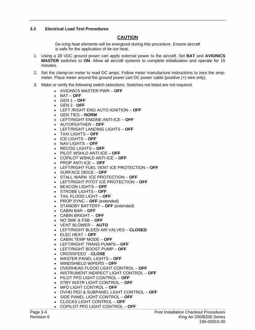
Page 3-4 Post Installation Checkout Procedures Revision 6 King Air 200/B200 Series 190-00915-00
3.3 Electrical Load Test Procedures
CAUTION De-icing heat elements will be energized during this procedure. Ensure aircraft is safe for the application of de-ice heat.
1. Using a 28 VDC ground power cart apply external power to the aircraft. Set BAT and AVIONICS MASTER switches to ON. Allow all aircraft systems to complete initialization and operate for 15 minutes.
2. Set the clamp-on meter to read DC amps. Follow meter manufacture instructions to zero the amp-meter. Place meter around the ground power cart DC power cable (positive (+) wire only).
3. Make or verify the following switch selections: Switches not listed are not required. • AVIONICS MASTER PWR – OFF • BAT – OFF • GEN 1 – OFF • GEN 2 - OFF • LEFT /RIGHT ENG AUTO IGNITION – OFF • GEN TIES – NORM • LEFT/RIGHT ENGINE ANTI-ICE – OFF • AUTOFEATHER – OFF • LEFT/RIGHT LANDING LIGHTS – OFF • TAXI LIGHTS – OFF • ICE LIGHTS – OFF • NAV LIGHTS – OFF • RECOG LIGHTS – OFF • PILOT WSHLD ANTI-ICE – OFF • COPILOT WSHLD ANTI-ICE – OFF • PROP ANTI-ICE – OFF • LEFT/RIGHT FUEL VENT ICE PROTECTION – OFF • SURFACE DEICE – OFF • STALL WARN ICE PROTECTION – OFF • LEFT/RIGHT PITOT ICE PROTECTION – OFF • BEACON LIGHTS – OFF • STROBE LIGHTS – OFF • TAIL FLOOD LIGHT – OFF • PROP SYNC – OFF (extended) • STANDBY BATTERY – OFF (extended) • CABIN BAR – OFF • CABIN BRIGHT – OFF • NO SMK & FSB – OFF • VENT BLOWER – AUTO • LEFT/RIGHT BLEED AIR VALVES – CLOSED • ELEC HEAT – OFF • CABIN TEMP MODE – OFF • LEFT/RIGHT TRANS PUMPS – OFF • LEFT/RIGHT BOOST PUMP – OFF • CROSSFEED - CLOSE • MASTER PANEL LIGHTS – OFF • WINDSHIELD WIPERS – OFF • OVERHEAD FLOOD LIGHT CONTROL – OFF • INSTRUMENT INDIRECT LIGHT CONTROL – OFF • PILOT PFD LIGHT CONTROL – OFF • STBY INSTR LIGHT CONTROL – OFF • MFD LIGHT CONTROL – OFF • OVHD PED & SUBPANEL LIGHT CONTROL – OFF • SIDE PANEL LIGHT CONTROL – OFF • CLOCKS LIGHT CONTROL – OFF • COPILOT PFD LIGHT CONTROL – OFF
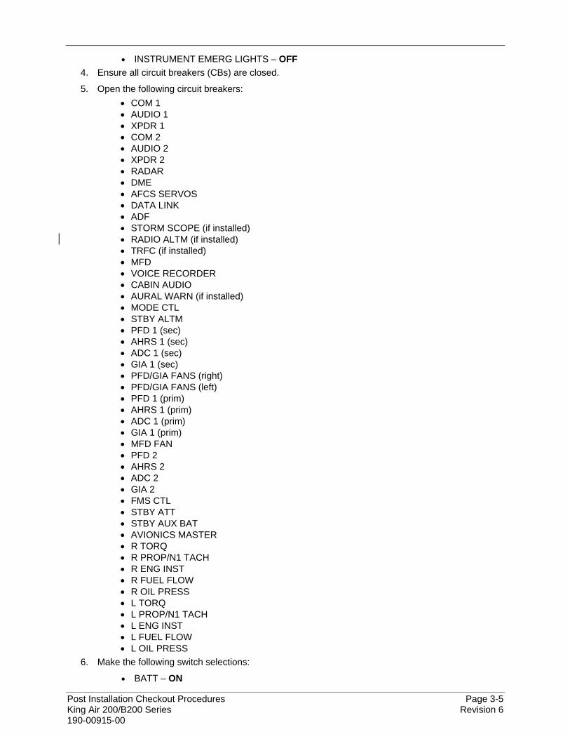
Post Installation Checkout Procedures Page 3-5 King Air 200/B200 Series Revision 6 190-00915-00
• INSTRUMENT EMERG LIGHTS – OFF 4. Ensure all circuit breakers (CBs) are closed.
5. Open the following circuit breakers: • COM 1 • AUDIO 1 • XPDR 1 • COM 2 • AUDIO 2 • XPDR 2 • RADAR • DME • AFCS SERVOS • DATA LINK • ADF • STORM SCOPE (if installed) • RADIO ALTM (if installed) • TRFC (if installed) • MFD • VOICE RECORDER • CABIN AUDIO • AURAL WARN (if installed) • MODE CTL • STBY ALTM • PFD 1 (sec) • AHRS 1 (sec) • ADC 1 (sec) • GIA 1 (sec) • PFD/GIA FANS (right) • PFD/GIA FANS (left) • PFD 1 (prim) • AHRS 1 (prim) • ADC 1 (prim) • GIA 1 (prim) • MFD FAN • PFD 2 • AHRS 2 • ADC 2 • GIA 2 • FMS CTL • STBY ATT • STBY AUX BAT • AVIONICS MASTER • R TORQ • R PROP/N1 TACH • R ENG INST • R FUEL FLOW • R OIL PRESS • L TORQ • L PROP/N1 TACH • L ENG INST • L FUEL FLOW • L OIL PRESS
6. Make the following switch selections:
• BATT – ON
Page 3-6 Post Installation Checkout Procedures Revision 6 King Air 200/B200 Series 190-00915-00
7. Observe the non-switchable DC electrical load (EXT PWR ON) from the amp meter and record in Table 3-1 as DP1. (Note: This load may be extremely low and can be considered negligible if under 1 amp)
8. Verify the aircraft is secure. This test should be limited in duration to minimize risks to the aircraft systems and/or airframe. Activate the following systems:
• ICE LIGHTS switch to ON • NAV LIGHTS switch to ON • BEACON LIGHTS switch to ON • STROBE LIGHTS switch to ON • TAIL FLOOD LIGHT switch to ON • LEFT/RIGHT LANDING LIGHTS switch to ON • TAXI LIGHTS switch to ON • RECOG LIGHTS switch to ON • PILOT WSHLD ANTI-ICE switch to NORMAL • COPILOT WSHLD ANTI-ICE switch to NORMAL • STALL WARN ICE PROTECTION switch to ON • LEFT/RIGHT FUEL VENT ICE PROTECTION switch to ON • LEFT/RIGHT PITOT ICE PROTECTION switch to ON • ELEC HEAT switch to ON • LEFT/RIGHT BLEED AIR VALVES switch to OPEN • LEFT/RIGHT ENGINE ANTI-ICE switch to ON • CABIN TEMP MODE switch to AUTO • PROP SYNC switch to ON (depressed) • BOOST PUMP-LEFT switch to ON • BOOST PUMP-RIGHT switch to ON • SURFACE DEICE switch to SINGLE
9. Observe the DC electrical load (EXT PWR ON, BATT charge, External lights, anti-ice systems) from the amp meter and record in Table 3-1 as DP2.
10. Turn off all switches referenced in Step 8.
11. Ensure that the circuit breakers in Step 5 are closed with the exception of RADAR circuit breaker.
12. Configure the aircraft to measure G1000/GFC700 system loads by making or verifying the following switch selections:
• EXT PWR – ON • AVIONICS MASTER PWR – ON • MASTER PANEL LIGHTS – ON • OVERHEAD FLOOD LIGHT CONTROL – ON and adjusted to max brightness • INSTRUMENT INDIRECT LIGHT CONTROL – ON and adjusted to max brightness • PILOT PFD LIGHT CONTROL – ON and adjusted to max brightness • STBY INST LIGHT CONTROL - ON and adjusted to max brightness • MFD LIGHT CONTROL - ON and adjusted to max brightness • OVHD PED & SUBPANEL LIGHT CONTROL - ON and adjusted to max brightness • SIDE PANEL LIGHT CONTROL - ON and adjusted to max brightness • CLOCKS LIGHT CONTROL - ON and adjusted to max brightness • COPILOT PFD LIGHT CONTROL - ON and adjusted to max brightness • INSTRUMENT EMERG LIGHTS – ON • CABIN BAR – ON • NO SMK & FSB – ON • CABIN FURN – ON
CAUTION NEVER OPERATE THE WINDSHIELD WIPERS ON A DRY WINDSHIELD - Remove the spring tension on the hub end of the wiper arm by inserting a 1/8-inch-diameter pin through the hole in each side of the wiper arm.
• WINDSHIELD WIPERS – SLOW • AUTOPILOT – ENGAGED with pitch, pitch trim, and roll servos running
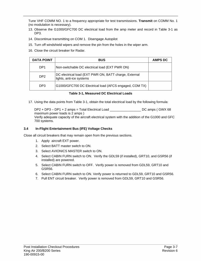
Post Installation Checkout Procedures Page 3-7 King Air 200/B200 Series Revision 6 190-00915-00
Tune VHF COMM NO. 1 to a frequency appropriate for test transmissions. Transmit on COMM No. 1 (no modulation is necessary). 13. Observe the G1000/GFC700 DC electrical load from the amp meter and record in Table 3-1 as
DP3.
14. Discontinue transmitting on COM 1. Disengage Autopilot
15. Turn off windshield wipers and remove the pin from the holes in the wiper arm.
16. Close the circuit breaker for Radar.
DATA POINT BUS AMPS DC
DP1 Non-switchable DC electrical load (EXT PWR ON)
DP2 DC electrical load (EXT PWR ON, BATT charge, External lights, anti-ice systems
DP3 G1000/GFC700 DC Electrical load (AFCS engaged, COM TX)
Table 3-1, Measured DC Electrical Loads
17. Using the data points from Table 3-1, obtain the total electrical load by the following formula: DP2 + DP3 – DP1 + 2 amps = Total Electrical Load _________________ DC amps ( GWX 68 maximum power loads is 2 amps ) Verify adequate capacity of the aircraft electrical system with the addition of the G1000 and GFC 700 systems.
3.4 In-Flight Entertainment Bus (IFE) Voltage Checks
Close all circuit breakers that may remain open from the previous sections. 1. Apply aircraft EXT power. 2. Select BATT master switch to ON. 3. Select AVIONICS MASTER switch to ON. 4. Select CABIN FURN switch to ON. Verify the GDL59 (if installed), GRT10, and GSR56 (if
installed) are powered. 5. Select CABIN FURN switch to OFF. Verify power is removed from GDL59, GRT10 and
GSR56. 6. Select CABIN FURN switch to ON. Verify power is returned to GDL59, GRT10 and GSR56. 7. Pull ENT circuit breaker. Verify power is removed from GDL59, GRT10 and GSR56.
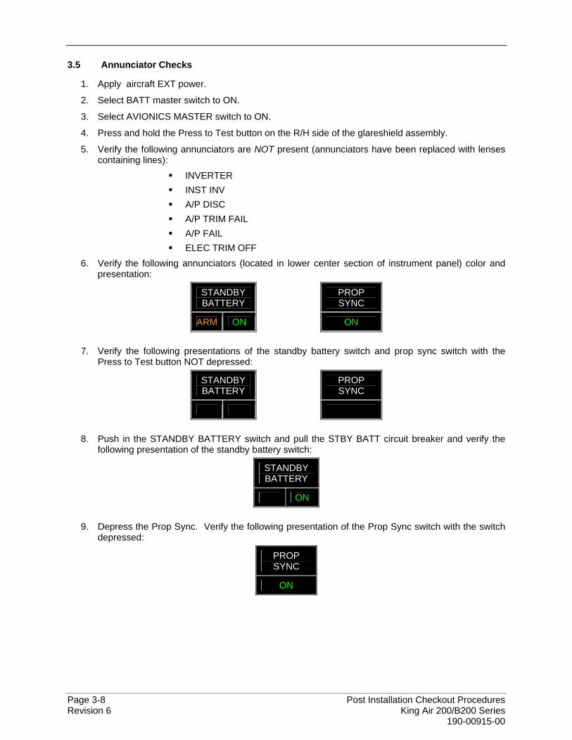
Page 3-8 Post Installation Checkout Procedures Revision 6 King Air 200/B200 Series 190-00915-00
3.5 Annunciator Checks
1. Apply aircraft EXT power.
2. Select BATT master switch to ON.
3. Select AVIONICS MASTER switch to ON.
4. Press and hold the Press to Test button on the R/H side of the glareshield assembly.
5. Verify the following annunciators are NOT present (annunciators have been replaced with lenses containing lines):
INVERTER INST INV A/P DISC A/P TRIM FAIL A/P FAIL ELEC TRIM OFF
6. Verify the following annunciators (located in lower center section of instrument panel) color and presentation:
STANDBY BATTERY
PROP SYNC
ARM ON
ON
7. Verify the following presentations of the standby battery switch and prop sync switch with the Press to Test button NOT depressed:
STANDBY BATTERY
PROP SYNC
8. Push in the STANDBY BATTERY switch and pull the STBY BATT circuit breaker and verify the following presentation of the standby battery switch:
STANDBY BATTERY
ON 9. Depress the Prop Sync. Verify the following presentation of the Prop Sync switch with the switch
depressed:
PROP SYNC
ON
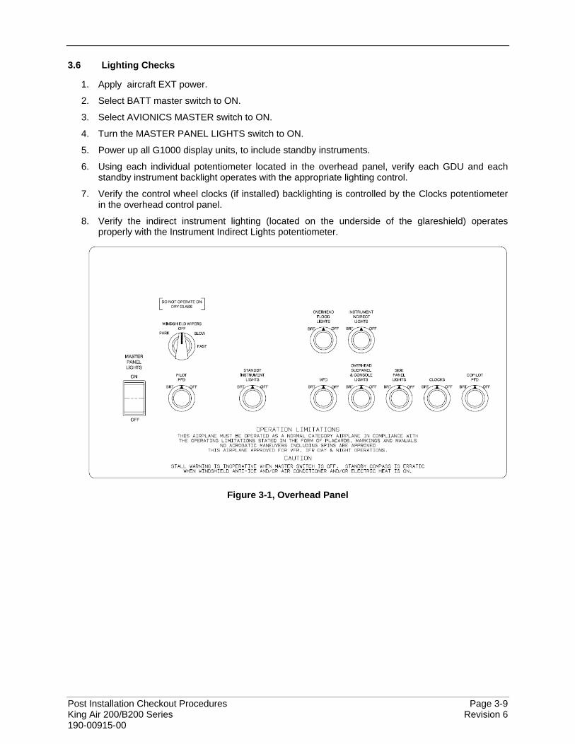
Post Installation Checkout Procedures Page 3-9 King Air 200/B200 Series Revision 6 190-00915-00
3.6 Lighting Checks
1. Apply aircraft EXT power.
2. Select BATT master switch to ON.
3. Select AVIONICS MASTER switch to ON.
4. Turn the MASTER PANEL LIGHTS switch to ON.
5. Power up all G1000 display units, to include standby instruments.
6. Using each individual potentiometer located in the overhead panel, verify each GDU and each standby instrument backlight operates with the appropriate lighting control.
7. Verify the control wheel clocks (if installed) backlighting is controlled by the Clocks potentiometer in the overhead control panel.
8. Verify the indirect instrument lighting (located on the underside of the glareshield) operates properly with the Instrument Indirect Lights potentiometer.
Figure 3-1, Overhead Panel
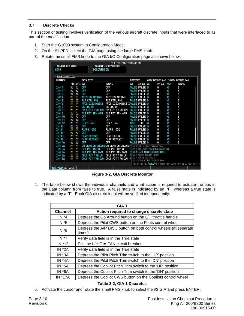
Page 3-10 Post Installation Checkout Procedures Revision 6 King Air 200/B200 Series 190-00915-00
3.7 Discrete Checks
This section of testing involves verification of the various aircraft discrete inputs that were interfaced to as part of the modification
1. Start the G1000 system in Configuration Mode. 2. On the #1 PFD, select the GIA page using the large FMS knob. 3. Rotate the small FMS knob to the GIA I/O Configuration page as shown below.
Figure 3-2, GIA Discrete Monitor
4. The table below shows the individual channels and what action is required to actuate the box in
the Data column from false to true. A false state is indicated by an ‘F’, whereas a true state is indicated by a ‘T’. Each GIA discrete input will be verified independently.
GIA 1
Channel Action required to change discrete state IN *4 Depress the Go Around button on the L/H throttle handle IN *5 Depress the Pilot CWS button on the Pilots control wheel
IN *6 Depress the A/P DISC button on both control wheels (at separate times)
IN *7 Verify data field is in the True state IN *12 Pull the L/H GIA FAN circuit breaker IN *2A Verify data field is in the True state IN *3A Depress the Pilot Pitch Trim switch to the ‘UP’ position IN *4A Depress the Pilot Pitch Trim switch to the ‘DN’ position IN *5A Depress the Copilot Pitch Trim switch to the ‘UP’ position IN *6A Depress the Copilot Pitch Trim switch to the ‘DN’ position
IN *17A Depress the Copilot CWS button on the Copilots control wheel Table 3-2, GIA 1 Discretes
5. Activate the cursor and rotate the small FMS knob to select the #2 GIA and press ENTER.
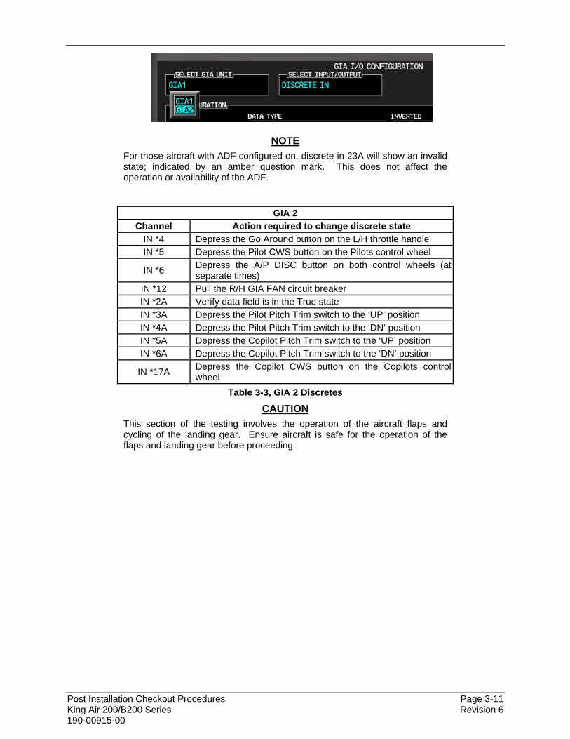
Post Installation Checkout Procedures Page 3-11 King Air 200/B200 Series Revision 6 190-00915-00
NOTE For those aircraft with ADF configured on, discrete in 23A will show an invalid state; indicated by an amber question mark. This does not affect the operation or availability of the ADF.
GIA 2 Channel Action required to change discrete state
IN *4 Depress the Go Around button on the L/H throttle handle IN *5 Depress the Pilot CWS button on the Pilots control wheel
IN *6 Depress the A/P DISC button on both control wheels (at separate times)
IN *12 Pull the R/H GIA FAN circuit breaker IN *2A Verify data field is in the True state IN *3A Depress the Pilot Pitch Trim switch to the ‘UP’ position IN *4A Depress the Pilot Pitch Trim switch to the ‘DN’ position IN *5A Depress the Copilot Pitch Trim switch to the ‘UP’ position IN *6A Depress the Copilot Pitch Trim switch to the ‘DN’ position
IN *17A Depress the Copilot CWS button on the Copilots control wheel
Table 3-3, GIA 2 Discretes
CAUTION This section of the testing involves the operation of the aircraft flaps and cycling of the landing gear. Ensure aircraft is safe for the operation of the flaps and landing gear before proceeding.
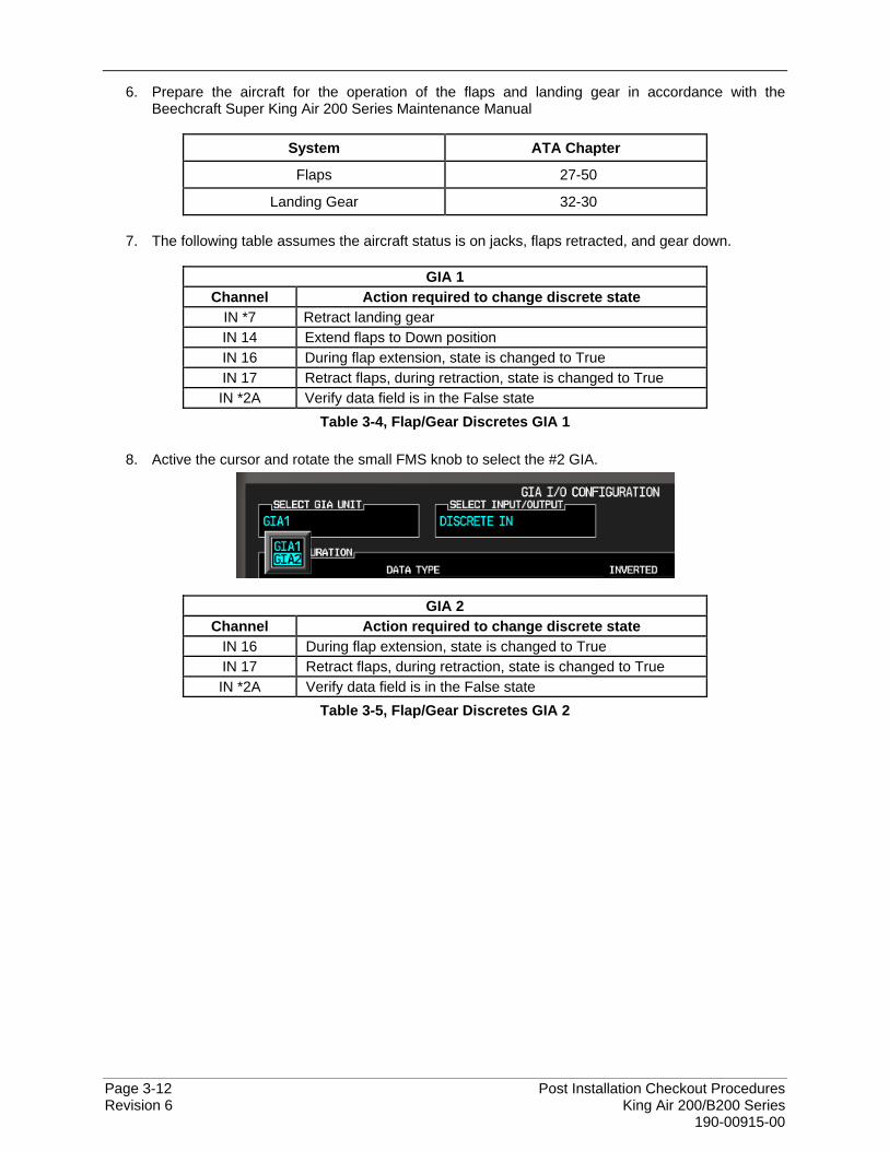
Page 3-12 Post Installation Checkout Procedures Revision 6 King Air 200/B200 Series 190-00915-00
6. Prepare the aircraft for the operation of the flaps and landing gear in accordance with the Beechcraft Super King Air 200 Series Maintenance Manual
System ATA Chapter
Flaps 27-50
Landing Gear 32-30 7. The following table assumes the aircraft status is on jacks, flaps retracted, and gear down.
GIA 1 Channel Action required to change discrete state
IN *7 Retract landing gear IN 14 Extend flaps to Down position IN 16 During flap extension, state is changed to True IN 17 Retract flaps, during retraction, state is changed to True IN *2A Verify data field is in the False state
Table 3-4, Flap/Gear Discretes GIA 1
8. Active the cursor and rotate the small FMS knob to select the #2 GIA.
GIA 2 Channel Action required to change discrete state
IN 16 During flap extension, state is changed to True IN 17 Retract flaps, during retraction, state is changed to True IN *2A Verify data field is in the False state
Table 3-5, Flap/Gear Discretes GIA 2
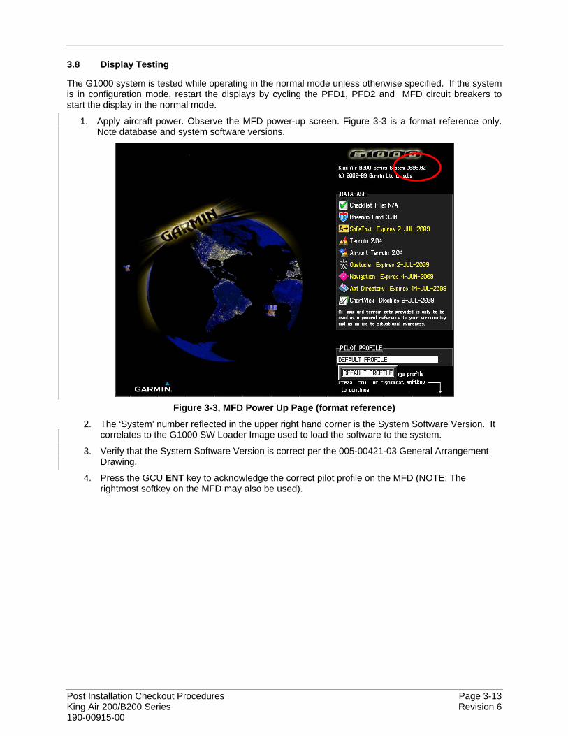
Post Installation Checkout Procedures Page 3-13 King Air 200/B200 Series Revision 6 190-00915-00
3.8 Display Testing
The G1000 system is tested while operating in the normal mode unless otherwise specified. If the system is in configuration mode, restart the displays by cycling the PFD1, PFD2 and MFD circuit breakers to start the display in the normal mode.
1. Apply aircraft power. Observe the MFD power-up screen. Figure 3-3 is a format reference only. Note database and system software versions.
Figure 3-3, MFD Power Up Page (format reference)
2. The ‘System’ number reflected in the upper right hand corner is the System Software Version. It correlates to the G1000 SW Loader Image used to load the software to the system.
3. Verify that the System Software Version is correct per the 005-00421-03 General Arrangement Drawing.
4. Press the GCU ENT key to acknowledge the correct pilot profile on the MFD (NOTE: The rightmost softkey on the MFD may also be used).
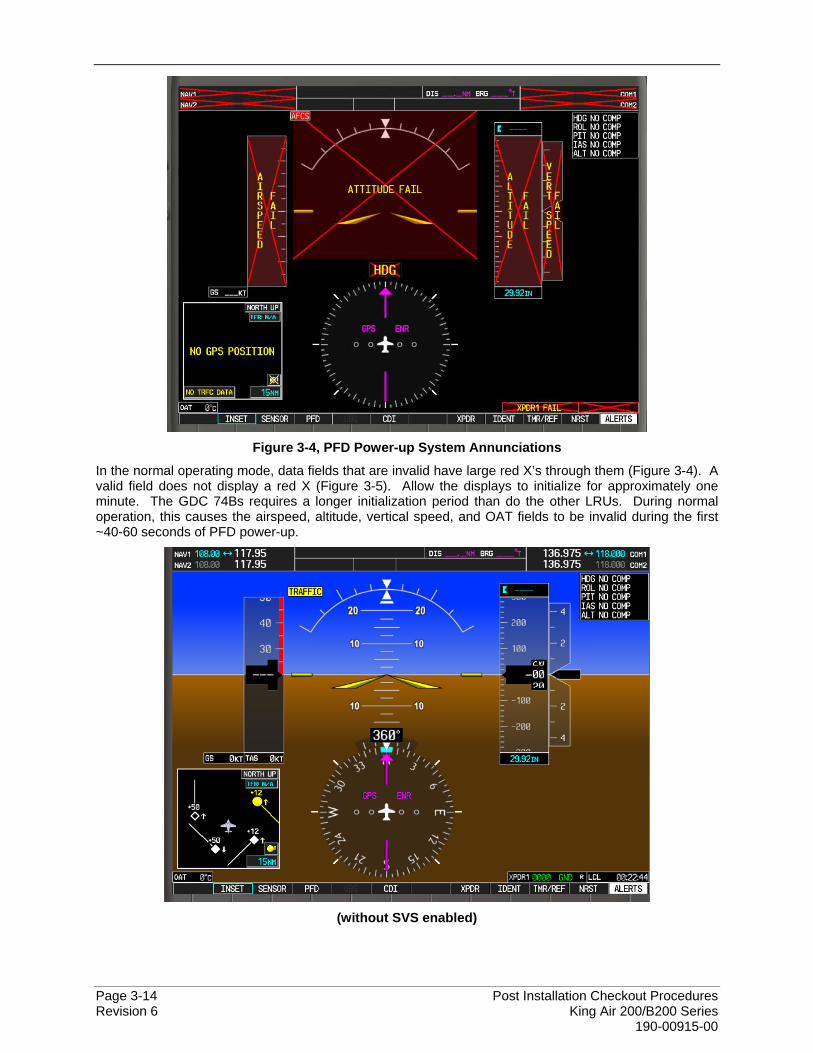
Page 3-14 Post Installation Checkout Procedures Revision 6 King Air 200/B200 Series 190-00915-00
Figure 3-4, PFD Power-up System Annunciations
In the normal operating mode, data fields that are invalid have large red X’s through them (Figure 3-4). A valid field does not display a red X (Figure 3-5). Allow the displays to initialize for approximately one minute. The GDC 74Bs requires a longer initialization period than do the other LRUs. During normal operation, this causes the airspeed, altitude, vertical speed, and OAT fields to be invalid during the first ~40-60 seconds of PFD power-up.
(without SVS enabled)
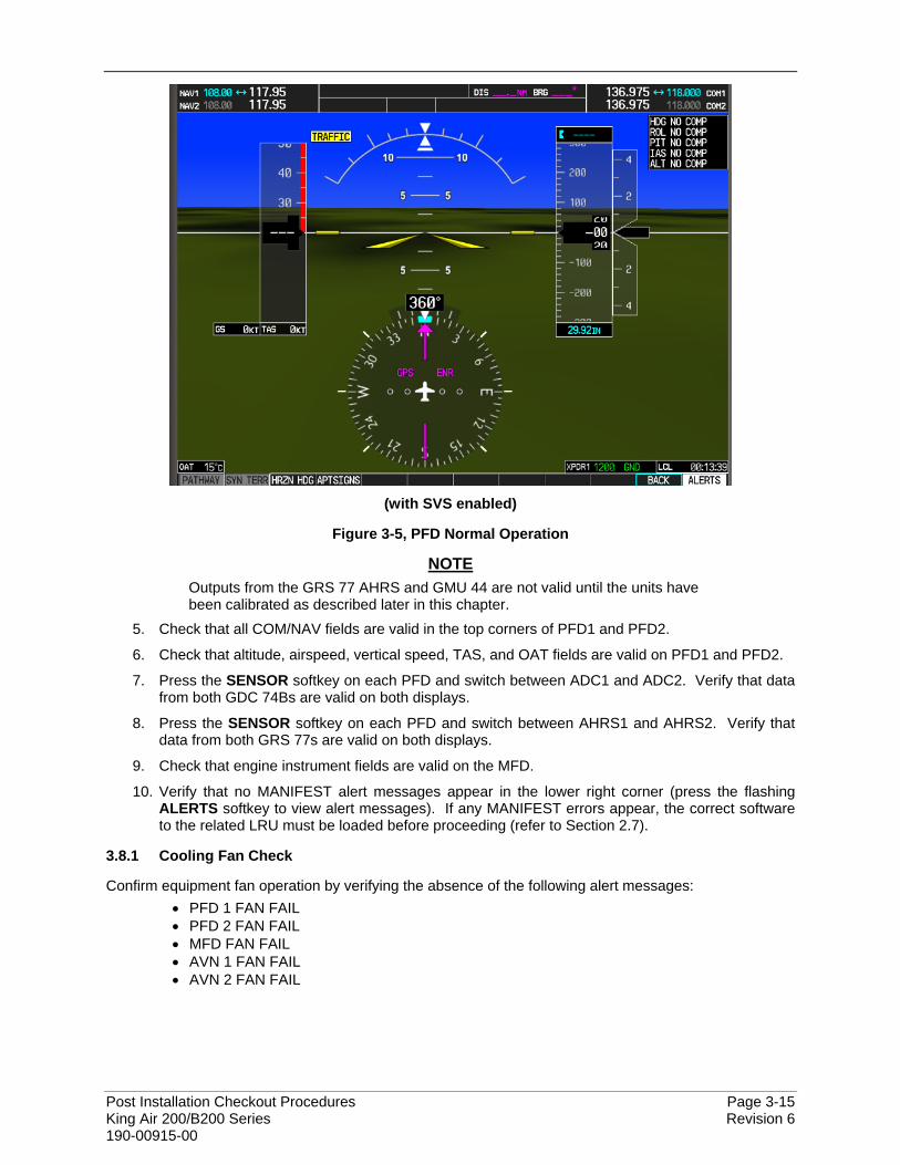
Post Installation Checkout Procedures Page 3-15 King Air 200/B200 Series Revision 6 190-00915-00
(with SVS enabled)
Figure 3-5, PFD Normal Operation
NOTE Outputs from the GRS 77 AHRS and GMU 44 are not valid until the units have been calibrated as described later in this chapter.
5. Check that all COM/NAV fields are valid in the top corners of PFD1 and PFD2.
6. Check that altitude, airspeed, vertical speed, TAS, and OAT fields are valid on PFD1 and PFD2.
7. Press the SENSOR softkey on each PFD and switch between ADC1 and ADC2. Verify that data from both GDC 74Bs are valid on both displays.
8. Press the SENSOR softkey on each PFD and switch between AHRS1 and AHRS2. Verify that data from both GRS 77s are valid on both displays.
9. Check that engine instrument fields are valid on the MFD.
10. Verify that no MANIFEST alert messages appear in the lower right corner (press the flashing ALERTS softkey to view alert messages). If any MANIFEST errors appear, the correct software to the related LRU must be loaded before proceeding (refer to Section 2.7).
3.8.1 Cooling Fan Check
Confirm equipment fan operation by verifying the absence of the following alert messages: • PFD 1 FAN FAIL • PFD 2 FAN FAIL • MFD FAN FAIL • AVN 1 FAN FAIL • AVN 2 FAN FAIL
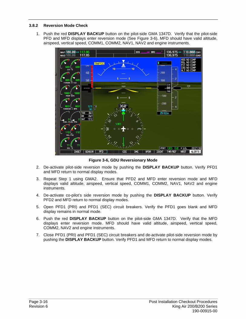
Page 3-16 Post Installation Checkout Procedures Revision 6 King Air 200/B200 Series 190-00915-00
3.8.2 Reversion Mode Check
1. Push the red DISPLAY BACKUP button on the pilot-side GMA 1347D. Verify that the pilot-side PFD and MFD displays enter reversion mode (See Figure 3-6). MFD should have valid altitude, airspeed, vertical speed, COMM1, COMM2, NAV1, NAV2 and engine instruments.
Figure 3-6, GDU Reversionary Mode
2. De-activate pilot-side reversion mode by pushing the DISPLAY BACKUP button. Verify PFD1 and MFD return to normal display modes.
3. Repeat Step 1 using GMA2. Ensure that PFD2 and MFD enter reversion mode and MFD displays valid altitude, airspeed, vertical speed, COMM1, COMM2, NAV1, NAV2 and engine instruments.
4. De-activate co-pilot’s side reversion mode by pushing the DISPLAY BACKUP button. Verify PFD2 and MFD return to normal display modes.
5. Open PFD1 (PRI) and PFD1 (SEC) circuit breakers. Verify the PFD1 goes blank and MFD display remains in normal mode.
6. Push the red DISPLAY BACKUP button on the pilot-side GMA 1347D. Verify that the MFD displays enter reversion mode. MFD should have valid altitude, airspeed, vertical speed, COMM2, NAV2 and engine instruments.
7. Close PFD1 (PRI) and PFD1 (SEC) circuit breakers and de-activate pilot-side reversion mode by pushing the DISPLAY BACKUP button. Verify PFD1 and MFD return to normal display modes.
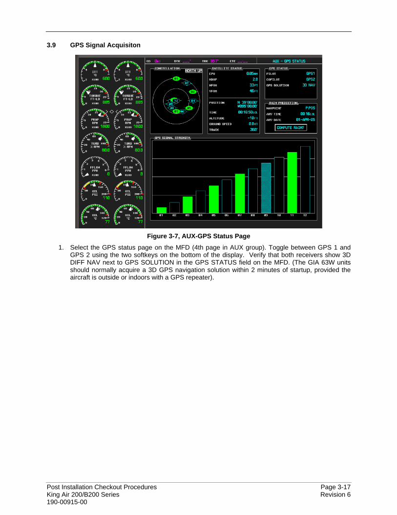
Post Installation Checkout Procedures Page 3-17 King Air 200/B200 Series Revision 6 190-00915-00
3.9 GPS Signal Acquisiton
Figure 3-7, AUX-GPS Status Page
1. Select the GPS status page on the MFD (4th page in AUX group). Toggle between GPS 1 and GPS 2 using the two softkeys on the bottom of the display. Verify that both receivers show 3D DIFF NAV next to GPS SOLUTION in the GPS STATUS field on the MFD. (The GIA 63W units should normally acquire a 3D GPS navigation solution within 2 minutes of startup, provided the aircraft is outside or indoors with a GPS repeater).
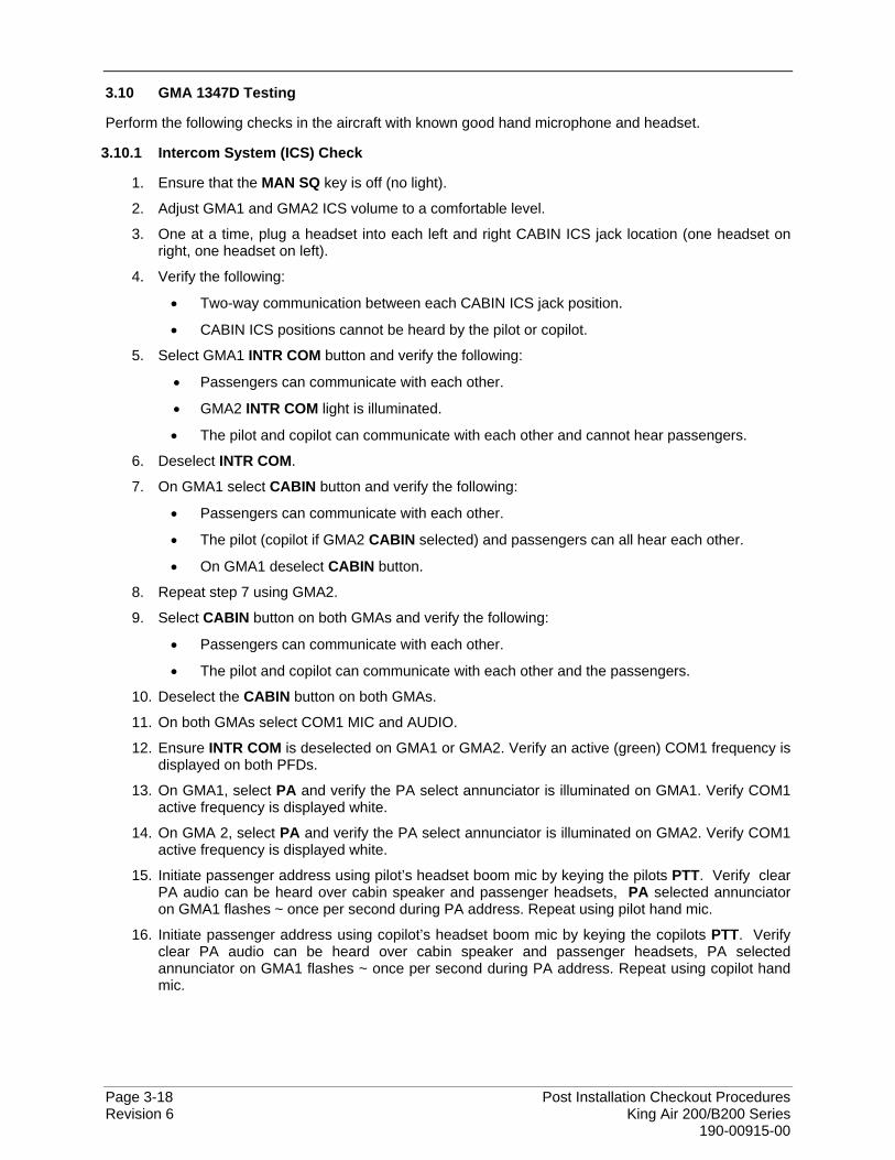
Page 3-18 Post Installation Checkout Procedures Revision 6 King Air 200/B200 Series 190-00915-00
3.10 GMA 1347D Testing
Perform the following checks in the aircraft with known good hand microphone and headset.
3.10.1 Intercom System (ICS) Check
1. Ensure that the MAN SQ key is off (no light).
2. Adjust GMA1 and GMA2 ICS volume to a comfortable level.
3. One at a time, plug a headset into each left and right CABIN ICS jack location (one headset on right, one headset on left).
4. Verify the following:
• Two-way communication between each CABIN ICS jack position.
• CABIN ICS positions cannot be heard by the pilot or copilot.
5. Select GMA1 INTR COM button and verify the following:
• Passengers can communicate with each other.
• GMA2 INTR COM light is illuminated.
• The pilot and copilot can communicate with each other and cannot hear passengers.
6. Deselect INTR COM.
7. On GMA1 select CABIN button and verify the following:
• Passengers can communicate with each other.
• The pilot (copilot if GMA2 CABIN selected) and passengers can all hear each other.
• On GMA1 deselect CABIN button.
8. Repeat step 7 using GMA2.
9. Select CABIN button on both GMAs and verify the following:
• Passengers can communicate with each other.
• The pilot and copilot can communicate with each other and the passengers.
10. Deselect the CABIN button on both GMAs.
11. On both GMAs select COM1 MIC and AUDIO.
12. Ensure INTR COM is deselected on GMA1 or GMA2. Verify an active (green) COM1 frequency is displayed on both PFDs.
13. On GMA1, select PA and verify the PA select annunciator is illuminated on GMA1. Verify COM1 active frequency is displayed white.
14. On GMA 2, select PA and verify the PA select annunciator is illuminated on GMA2. Verify COM1 active frequency is displayed white.
15. Initiate passenger address using pilot’s headset boom mic by keying the pilots PTT. Verify clear PA audio can be heard over cabin speaker and passenger headsets, PA selected annunciator on GMA1 flashes ~ once per second during PA address. Repeat using pilot hand mic.
16. Initiate passenger address using copilot’s headset boom mic by keying the copilots PTT. Verify clear PA audio can be heard over cabin speaker and passenger headsets, PA selected annunciator on GMA1 flashes ~ once per second during PA address. Repeat using copilot hand mic.
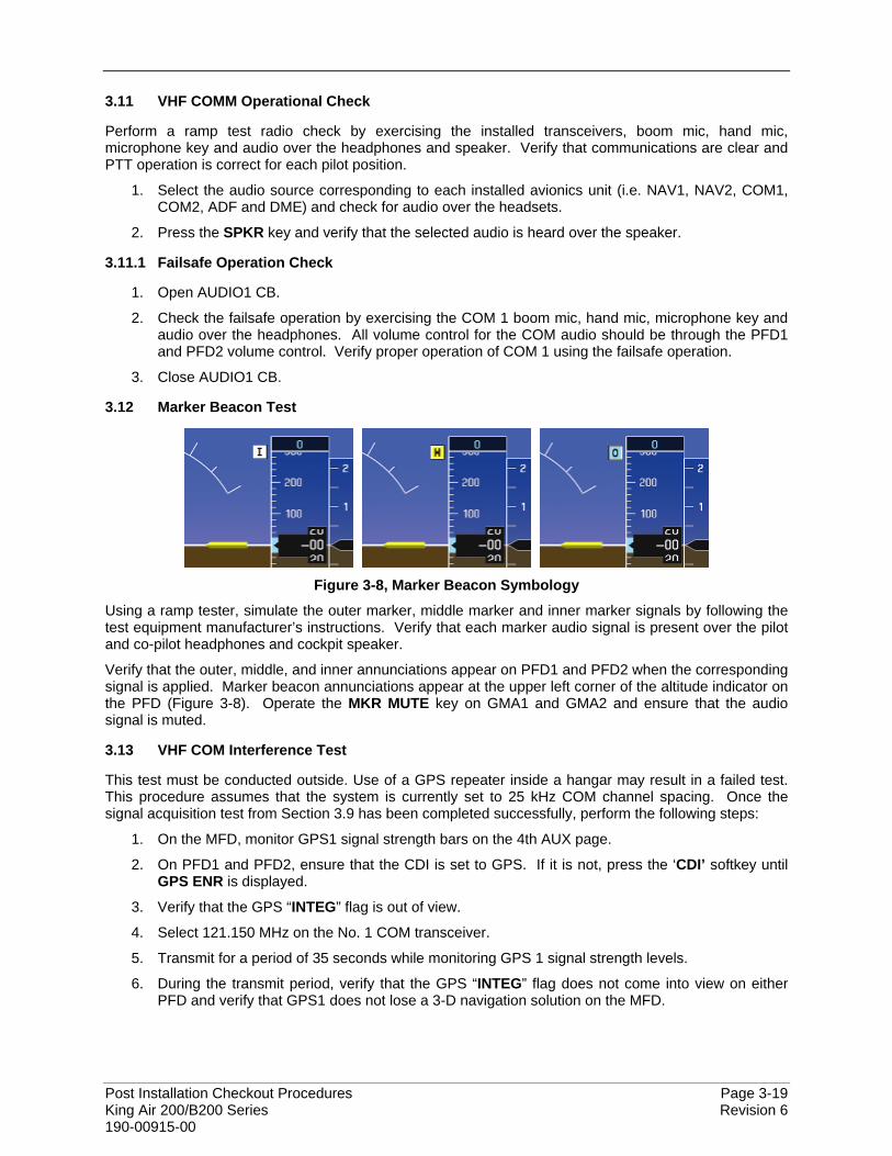
Post Installation Checkout Procedures Page 3-19 King Air 200/B200 Series Revision 6 190-00915-00
3.11 VHF COMM Operational Check
Perform a ramp test radio check by exercising the installed transceivers, boom mic, hand mic, microphone key and audio over the headphones and speaker. Verify that communications are clear and PTT operation is correct for each pilot position.
1. Select the audio source corresponding to each installed avionics unit (i.e. NAV1, NAV2, COM1, COM2, ADF and DME) and check for audio over the headsets.
2. Press the SPKR key and verify that the selected audio is heard over the speaker.
3.11.1 Failsafe Operation Check
1. Open AUDIO1 CB.
2. Check the failsafe operation by exercising the COM 1 boom mic, hand mic, microphone key and audio over the headphones. All volume control for the COM audio should be through the PFD1 and PFD2 volume control. Verify proper operation of COM 1 using the failsafe operation.
3. Close AUDIO1 CB.
3.12 Marker Beacon Test
Figure 3-8, Marker Beacon Symbology
Using a ramp tester, simulate the outer marker, middle marker and inner marker signals by following the test equipment manufacturer’s instructions. Verify that each marker audio signal is present over the pilot and co-pilot headphones and cockpit speaker.
Verify that the outer, middle, and inner annunciations appear on PFD1 and PFD2 when the corresponding signal is applied. Marker beacon annunciations appear at the upper left corner of the altitude indicator on the PFD (Figure 3-8). Operate the MKR MUTE key on GMA1 and GMA2 and ensure that the audio signal is muted.
3.13 VHF COM Interference Test
This test must be conducted outside. Use of a GPS repeater inside a hangar may result in a failed test. This procedure assumes that the system is currently set to 25 kHz COM channel spacing. Once the signal acquisition test from Section 3.9 has been completed successfully, perform the following steps:
1. On the MFD, monitor GPS1 signal strength bars on the 4th AUX page.
2. On PFD1 and PFD2, ensure that the CDI is set to GPS. If it is not, press the ‘CDI’ softkey until GPS ENR is displayed.
3. Verify that the GPS “INTEG” flag is out of view.
4. Select 121.150 MHz on the No. 1 COM transceiver.
5. Transmit for a period of 35 seconds while monitoring GPS 1 signal strength levels.
6. During the transmit period, verify that the GPS “INTEG” flag does not come into view on either PFD and verify that GPS1 does not lose a 3-D navigation solution on the MFD.
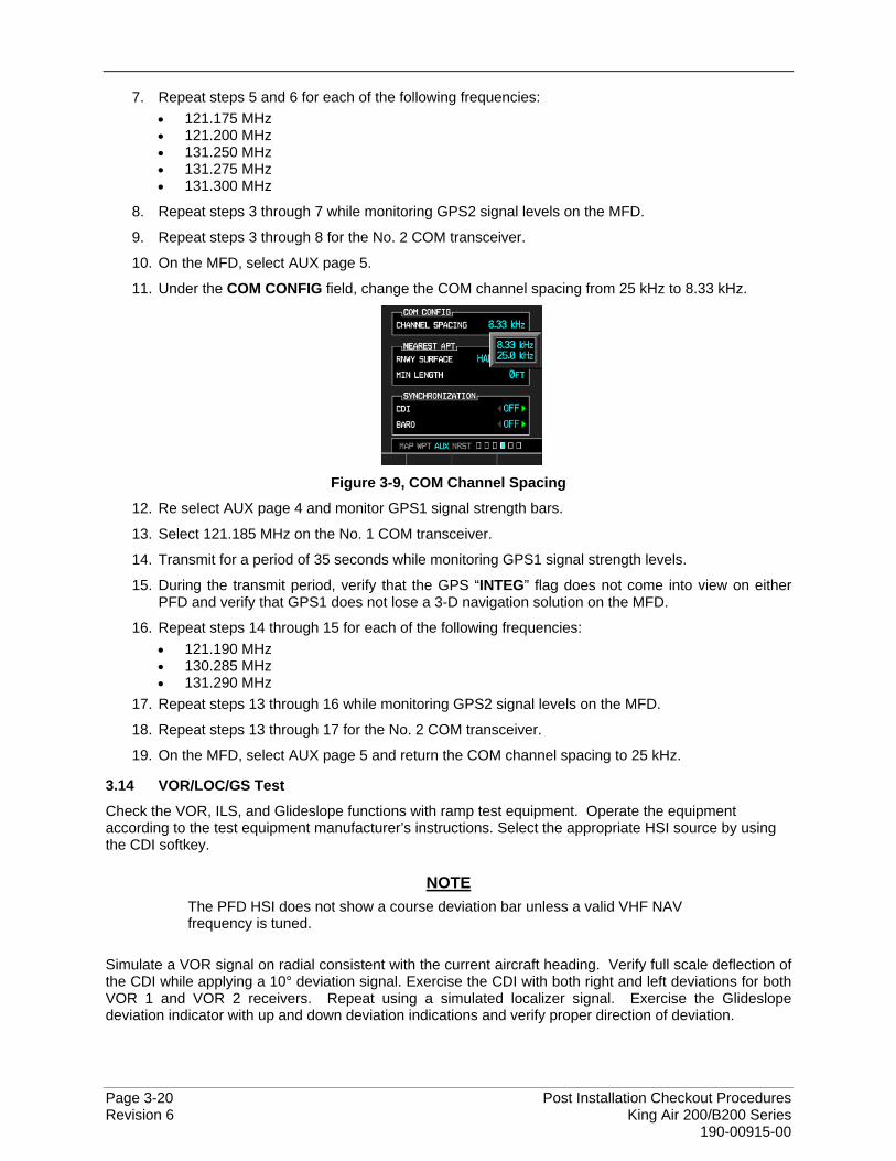
Page 3-20 Post Installation Checkout Procedures Revision 6 King Air 200/B200 Series 190-00915-00
7. Repeat steps 5 and 6 for each of the following frequencies: • 121.175 MHz • 121.200 MHz • 131.250 MHz • 131.275 MHz • 131.300 MHz
8. Repeat steps 3 through 7 while monitoring GPS2 signal levels on the MFD.
9. Repeat steps 3 through 8 for the No. 2 COM transceiver.
10. On the MFD, select AUX page 5.
11. Under the COM CONFIG field, change the COM channel spacing from 25 kHz to 8.33 kHz.
Figure 3-9, COM Channel Spacing
12. Re select AUX page 4 and monitor GPS1 signal strength bars.
13. Select 121.185 MHz on the No. 1 COM transceiver.
14. Transmit for a period of 35 seconds while monitoring GPS1 signal strength levels.
15. During the transmit period, verify that the GPS “INTEG” flag does not come into view on either PFD and verify that GPS1 does not lose a 3-D navigation solution on the MFD.
16. Repeat steps 14 through 15 for each of the following frequencies: • 121.190 MHz • 130.285 MHz • 131.290 MHz
17. Repeat steps 13 through 16 while monitoring GPS2 signal levels on the MFD.
18. Repeat steps 13 through 17 for the No. 2 COM transceiver.
19. On the MFD, select AUX page 5 and return the COM channel spacing to 25 kHz.
3.14 VOR/LOC/GS Test
Check the VOR, ILS, and Glideslope functions with ramp test equipment. Operate the equipment according to the test equipment manufacturer’s instructions. Select the appropriate HSI source by using the CDI softkey.
NOTE The PFD HSI does not show a course deviation bar unless a valid VHF NAV frequency is tuned.
Simulate a VOR signal on radial consistent with the current aircraft heading. Verify full scale deflection of the CDI while applying a 10° deviation signal. Exercise the CDI with both right and left deviations for both VOR 1 and VOR 2 receivers. Repeat using a simulated localizer signal. Exercise the Glideslope deviation indicator with up and down deviation indications and verify proper direction of deviation.

Post Installation Checkout Procedures Page 3-21 King Air 200/B200 Series Revision 6 190-00915-00
3.15 COM Antenna VSWR Checks
Check for insertion loss and VSWR (Voltage Standing Wave Ratio). VSWR should be checked with an in-line type VSWR/wattmeter inserted in the coaxial transmission line between the transceiver and the antenna. The VSWR should be inserted as close to the transceiver as possible. Any problem with the antenna installation is most likely seen as high reflected power. A VSWR of 3:1 may result in up to a 50% loss in transmit power. Ideally, the VSWR should be 2.5:1 or less.
3.16 GTX 33( ) Testing
Operation of the GTX 33 or GTX 33D transponder is accomplished using PFD1, PFD2 or MFD. Refer to G1000 Pilot’s Guide for Hawker Beechcraft 200/B200 King Air Cockpit Reference Guide, Garmin P/N 190-00929-01 for basic operation.
The integrated transponder/altitude reporting system must be verified in accordance with Title 14 of the Code of Federal Regulations (14 CFR) §§ 91.411 and 91.413. These tests require the use of a Mode S ramp generator. Specific instructions for operating the ramp tester are contained in the applicable operator's manual. Refer to 14 CFR Part 43 Appendices E and F for testing criteria.
Note that for GTX 33D units, the aircraft must be put on jacks to simulate an in-air condition in order to test the Mode S diversity transmission channel isolation.

Page 3-22 Post Installation Checkout Procedures Revision 6 King Air 200/B200 Series 190-00915-00
3.17 Pitot Static System Leak Checks
With a pitot-static test set connected to the aircraft perform a leak test of the aircraft static plumbing at an altitude of 30,000 ft and airspeed of 120 knots. When static pressure has stabilized, verify and record the cumulative leak rate is 300ft/minute or less.
ALTITUDE ft/min:
With a pitot-static test set connected to the aircraft perform a leak test of the aircraft pitot plumbing with the static system at ‘ground’ and an airspeed of 200 knots. When pitot pressure has stabilized, verify and record the cumulative leak rate is 1 knot/minute or less.
AIRSPEED kts/min:
3.18 GDC 74B Testing
3.18.1 Preparation for Air Data Validation Test
Verification of the altimeter and airspeed must be performed using an air data test set (ADTS). The pitot / static system and altimeter must be verified in accordance with Title 14 of the Code of Federal Regulations (CFR) § 91.411 and Part 43 Appendix E. PFD1 must be in configuration mode and the MFD must be in Reversionary mode to perform the tests as outlined in Part 43 Appendix E.
To prepare the G1000 System for Part 43 Appendix E testing:
1. Start the G1000 system in normal mode.
2. Remove power to PFD1 by opening the PFD1 (PRI) and PFD1 (SEC) circuit breakers.
3. Start PFD1 in configuration mode.
4. Release the ENT key after “INITIALIZING SYSTEM” appears in the upper left corner of PFD1.
CAUTION Configuration mode contains certain pages and settings that are critical to aircraft operation and safety. These pages are protected and cannot be modified, unless the technician is properly authorized and equipped. However, most protected pages are viewable to allow system awareness for troubleshooting.
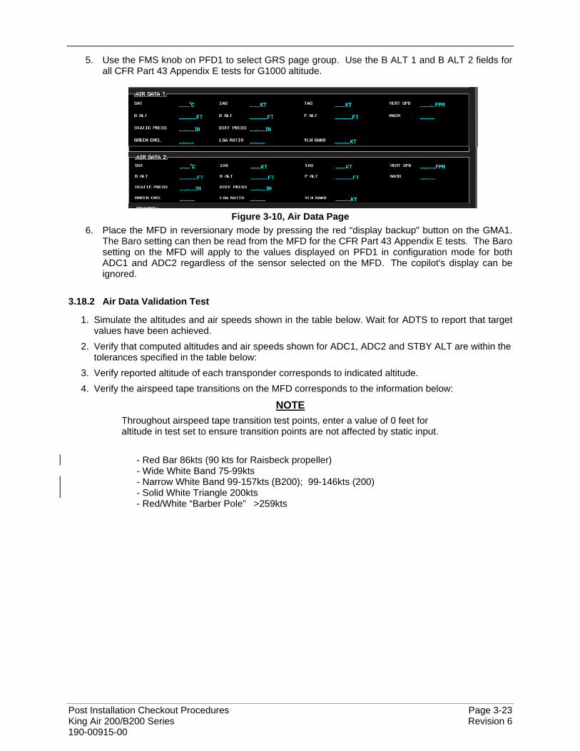
Post Installation Checkout Procedures Page 3-23 King Air 200/B200 Series Revision 6 190-00915-00
5. Use the FMS knob on PFD1 to select GRS page group. Use the B ALT 1 and B ALT 2 fields for all CFR Part 43 Appendix E tests for G1000 altitude.
Figure 3-10, Air Data Page
6. Place the MFD in reversionary mode by pressing the red “display backup” button on the GMA1. The Baro setting can then be read from the MFD for the CFR Part 43 Appendix E tests. The Baro setting on the MFD will apply to the values displayed on PFD1 in configuration mode for both ADC1 and ADC2 regardless of the sensor selected on the MFD. The copilot's display can be ignored.
3.18.2 Air Data Validation Test
1. Simulate the altitudes and air speeds shown in the table below. Wait for ADTS to report that target values have been achieved.
2. Verify that computed altitudes and air speeds shown for ADC1, ADC2 and STBY ALT are within the tolerances specified in the table below:
3. Verify reported altitude of each transponder corresponds to indicated altitude. 4. Verify the airspeed tape transitions on the MFD corresponds to the information below:
NOTE Throughout airspeed tape transition test points, enter a value of 0 feet for altitude in test set to ensure transition points are not affected by static input.
- Red Bar 86kts (90 kts for Raisbeck propeller)
- Wide White Band 75-99kts - Narrow White Band 99-157kts (B200); 99-146kts (200) - Solid White Triangle 200kts
- Red/White “Barber Pole” >259kts
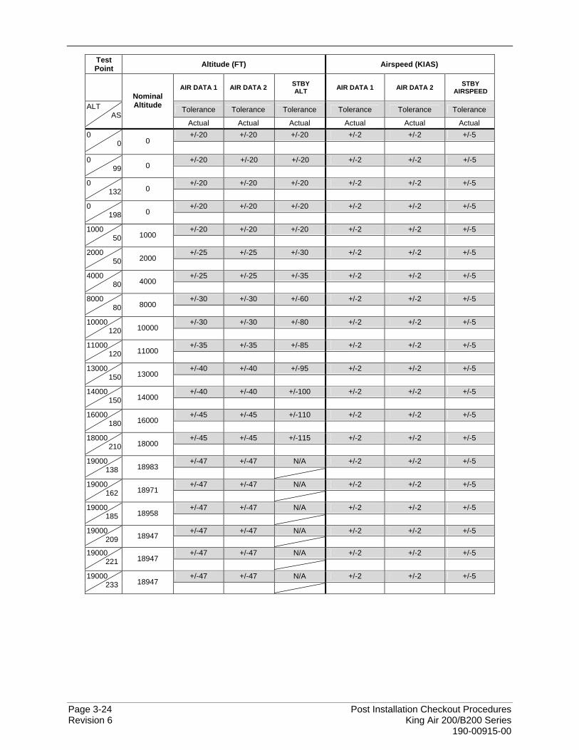
Page 3-24 Post Installation Checkout Procedures Revision 6 King Air 200/B200 Series 190-00915-00
Test Point Altitude (FT) Airspeed (KIAS)
AIR DATA 1 AIR DATA 2 STBY
ALT AIR DATA 1 AIR DATA 2 STBY AIRSPEED
Tolerance Tolerance Tolerance Tolerance Tolerance Tolerance ALT AS
Nominal Altitude
Actual Actual Actual Actual Actual Actual +/-20 +/-20 +/-20 +/-2 +/-2 +/-5 0
0 0
+/-20 +/-20 +/-20 +/-2 +/-2 +/-5 0 99 0
+/-20 +/-20 +/-20 +/-2 +/-2 +/-5 0
132 0
+/-20 +/-20 +/-20 +/-2 +/-2 +/-5 0 198 0
+/-20 +/-20 +/-20 +/-2 +/-2 +/-5 1000
50 1000
+/-25 +/-25 +/-30 +/-2 +/-2 +/-5 2000 50 2000
+/-25 +/-25 +/-35 +/-2 +/-2 +/-5 4000
80 4000
+/-30 +/-30 +/-60 +/-2 +/-2 +/-5 8000 80 8000
+/-30 +/-30 +/-80 +/-2 +/-2 +/-5 10000
120 10000
+/-35 +/-35 +/-85 +/-2 +/-2 +/-5 11000 120 11000
+/-40 +/-40 +/-95 +/-2 +/-2 +/-5 13000
150 13000
+/-40 +/-40 +/-100 +/-2 +/-2 +/-5 14000 150 14000
+/-45 +/-45 +/-110 +/-2 +/-2 +/-5 16000
180 16000
+/-45 +/-45 +/-115 +/-2 +/-2 +/-5 18000 210 18000
+/-47 +/-47 N/A +/-2 +/-2 +/-5 19000
138 18983
+/-47 +/-47 N/A +/-2 +/-2 +/-5 19000 162 18971
+/-47 +/-47 N/A +/-2 +/-2 +/-5 19000
185 18958
+/-47 +/-47 N/A +/-2 +/-2 +/-5 19000 209 18947
+/-47 +/-47 N/A +/-2 +/-2 +/-5 19000
221 18947
+/-47 +/-47 N/A +/-2 +/-2 +/-5 19000 233 18947
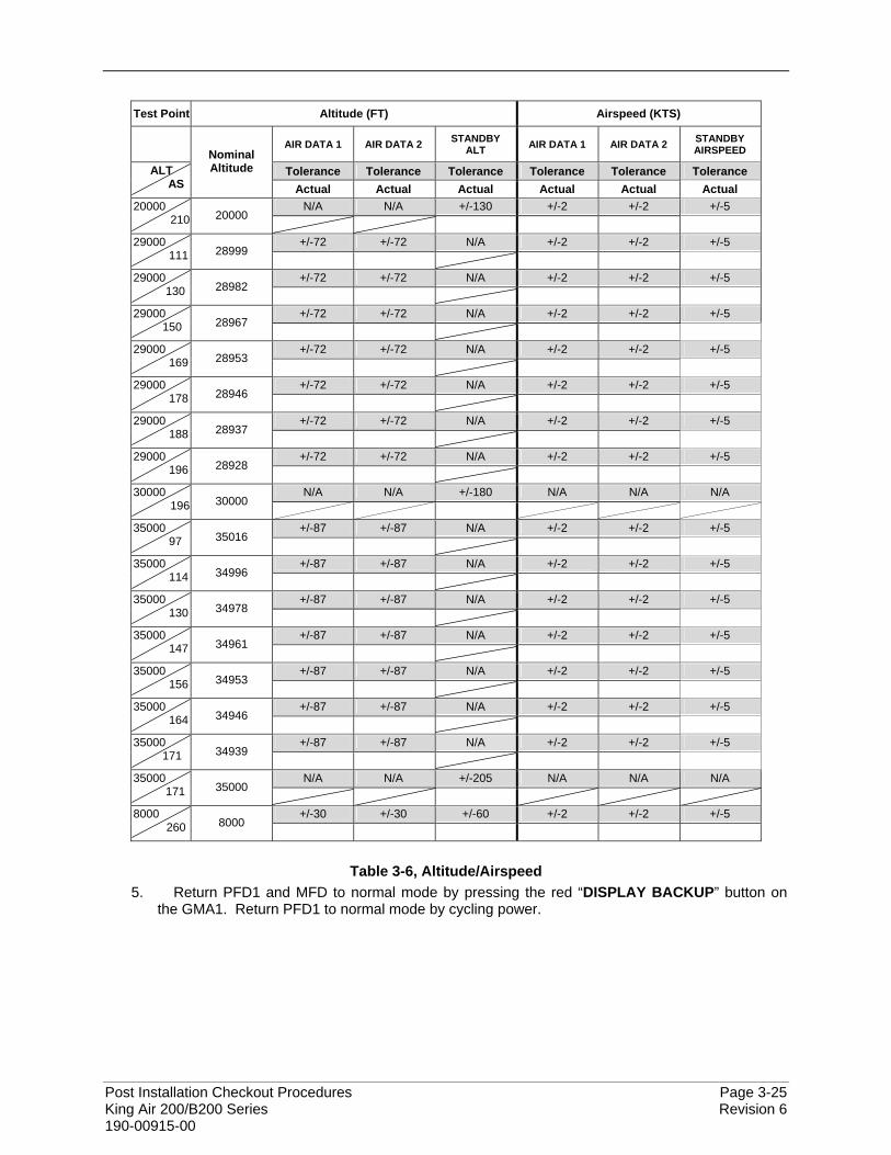
Post Installation Checkout Procedures Page 3-25 King Air 200/B200 Series Revision 6 190-00915-00
Test Point Altitude (FT) Airspeed (KTS)
AIR DATA 1 AIR DATA 2 STANDBY
ALT AIR DATA 1 AIR DATA 2 STANDBY AIRSPEED
Tolerance Tolerance Tolerance Tolerance Tolerance Tolerance ALT AS
Nominal Altitude
Actual Actual Actual Actual Actual Actual N/A N/A +/-130 +/-2 +/-2 +/-5 20000
210 20000
+/-72 +/-72 N/A +/-2 +/-2 +/-5 29000 111 28999
+/-72 +/-72 N/A +/-2 +/-2 +/-5 29000
130 28982
+/-72 +/-72 N/A +/-2 +/-2 +/-5 29000 150 28967
+/-72 +/-72 N/A +/-2 +/-2 +/-5 29000
169 28953
+/-72 +/-72 N/A +/-2 +/-2 +/-5 29000 178 28946
+/-72 +/-72 N/A +/-2 +/-2 +/-5 29000
188 28937
+/-72 +/-72 N/A +/-2 +/-2 +/-5 29000 196 28928
N/A N/A +/-180 N/A N/A N/A 30000
196 30000
+/-87 +/-87 N/A +/-2 +/-2 +/-5 35000 97 35016
+/-87 +/-87 N/A +/-2 +/-2 +/-5 35000
114 34996
+/-87 +/-87 N/A +/-2 +/-2 +/-5 35000 130 34978
+/-87 +/-87 N/A +/-2 +/-2 +/-5 35000
147 34961
+/-87 +/-87 N/A +/-2 +/-2 +/-5 35000 156 34953
+/-87 +/-87 N/A +/-2 +/-2 +/-5 35000
164 34946
+/-87 +/-87 N/A +/-2 +/-2 +/-5 35000 171 34939
N/A N/A +/-205 N/A N/A N/A 35000
171 35000
+/-30 +/-30 +/-60 +/-2 +/-2 +/-5 8000 260 8000
Table 3-6, Altitude/Airspeed
5. Return PFD1 and MFD to normal mode by pressing the red “DISPLAY BACKUP” button on the GMA1. Return PFD1 to normal mode by cycling power.
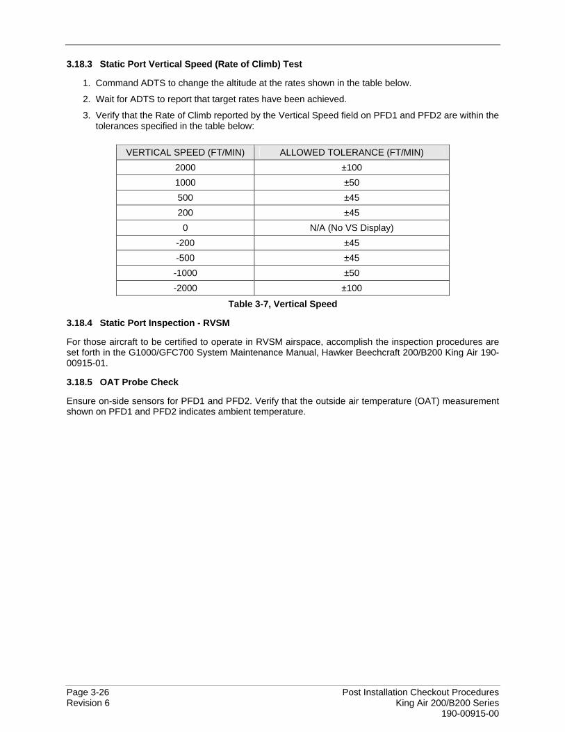
Page 3-26 Post Installation Checkout Procedures Revision 6 King Air 200/B200 Series 190-00915-00
3.18.3 Static Port Vertical Speed (Rate of Climb) Test
1. Command ADTS to change the altitude at the rates shown in the table below.
2. Wait for ADTS to report that target rates have been achieved.
3. Verify that the Rate of Climb reported by the Vertical Speed field on PFD1 and PFD2 are within the tolerances specified in the table below:
VERTICAL SPEED (FT/MIN) ALLOWED TOLERANCE (FT/MIN) 2000 ±100 1000 ±50 500 ±45 200 ±45
0 N/A (No VS Display) -200 ±45 -500 ±45 -1000 ±50 -2000 ±100
Table 3-7, Vertical Speed
3.18.4 Static Port Inspection - RVSM
For those aircraft to be certified to operate in RVSM airspace, accomplish the inspection procedures are set forth in the G1000/GFC700 System Maintenance Manual, Hawker Beechcraft 200/B200 King Air 190-00915-01.
3.18.5 OAT Probe Check
Ensure on-side sensors for PFD1 and PFD2. Verify that the outside air temperature (OAT) measurement shown on PFD1 and PFD2 indicates ambient temperature.
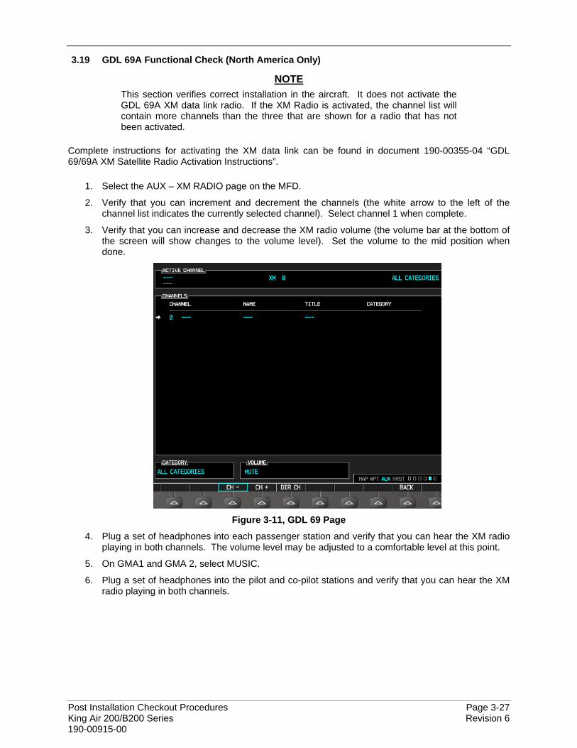
Post Installation Checkout Procedures Page 3-27 King Air 200/B200 Series Revision 6 190-00915-00
3.19 GDL 69A Functional Check (North America Only)
NOTE This section verifies correct installation in the aircraft. It does not activate the GDL 69A XM data link radio. If the XM Radio is activated, the channel list will contain more channels than the three that are shown for a radio that has not been activated.
Complete instructions for activating the XM data link can be found in document 190-00355-04 “GDL 69/69A XM Satellite Radio Activation Instructions”.
1. Select the AUX – XM RADIO page on the MFD.
2. Verify that you can increment and decrement the channels (the white arrow to the left of the channel list indicates the currently selected channel). Select channel 1 when complete.
3. Verify that you can increase and decrease the XM radio volume (the volume bar at the bottom of the screen will show changes to the volume level). Set the volume to the mid position when done.
Figure 3-11, GDL 69 Page
4. Plug a set of headphones into each passenger station and verify that you can hear the XM radio playing in both channels. The volume level may be adjusted to a comfortable level at this point.
5. On GMA1 and GMA 2, select MUSIC.
6. Plug a set of headphones into the pilot and co-pilot stations and verify that you can hear the XM radio playing in both channels.
Page 3-28 Post Installation Checkout Procedures Revision 6 King Air 200/B200 Series 190-00915-00
3.19.1 XM Audio Muting Check – (Aircraft Equipped with a Tone Generator)
NOTE This procedure is only applicable to aircraft serial numbers equipped with a tone generator as part of the aircraft audio system. Refer to the appropriate aircraft wiring diagrams to determine if a tone generator is installed.
1. Select the AUX – XM RADIO page on the MFD.
2. Plug a set of headphones into the pilot and co-pilot stations and verify that you can hear the XM radio playing in both channels.
3. Restart PFD1 in configuration mode.
4. Select page 4, Audio Alert Configuration, from the Systems menu by rotating the small FMS knob.
5. Select PLAY for the following audio and verify XM audio is temporarily muted while alert audio is being played.
• GEAR • STALL
6. Verify XM audio is temporarily muted while alert audio is being played.
7. Restart PFD1 in normal mode.
WARNING! The following step requires moving the stall warning vane. Use caution when handling the stall warning vane.
8. While monitoring pilot and copilot XM audio, actuate the stall warn transducer on the left wing leading edge in an up position (for those aircraft equipped with a Safeflight computer, actuate in the aft position), verify the following:
• Stall warning tone is active.
• Pilot and copilot XM audio is muted.
9. Release the stall warning transducer in the left wing leading edge, verify the following:
• Stall warning tone is silenced.
10. Verify XM audio returns.
Post Installation Checkout Procedures Page 3-29 King Air 200/B200 Series Revision 6 190-00915-00
3.19.2 XM Audio Muting Check – (Aircraft Not Equipped with a Tone Generator)
GDL69 discrete inputs from stall warning and landing gear control systems as detailed in 005-W0025-00 “Wiring Diagram, G1000 / GFC 700 King Air 200 B200” are required for aircraft not equipped with a tone generator.
NOTE This procedure is only applicable to aircraft serial numbers that do not employ a tone generator as part of the aircraft audio system. Refer to the appropriate aircraft wiring diagrams to determine if a tone generator is installed.
WARNING! THE FOLLOWING PROCEDURES REQUIRES OPERATION OF THE AIRCRAFT LANDING GEAR. OBSERVE ALL APPLICABLE SAFETY PRECAUTIONS. BEFORE WORKING IN ANY LANDING GEAR WHEEL WELL, ENSURE THAT ALL LANDING GEAR AND GEAR DOOR SAFETY DEVICES ARE INSTALLED. EXERCISE EXTREME CAUTION WHILE WORKING AROUND LANDING GEAR OR IN LANDING GEAR WHEEL WELLS.
Gear warning discrete
1. Reference Hawker Beechcraft aircraft maintenance manual (101-590010-19) and jack aircraft to allow operation of landing gear.
2. Select the AUX – XM RADIO page on the MFD. 3. Plug a set of headphones into the pilot and co-pilot stations and verify that you can hear the XM
radio playing in both channels. Adjust volume to a comfortable level. 4. Ensure both left and right throttles are at IDLE position. 5. Retract landing gear to the full up and locked position. 6. Verify the landing gear warning horn is active. 7. Verify XM audio is muted in the pilot and co-pilot stations. 8. Increase both left and right throttles forward of IDLE position (towards takeoff position). 9. Verify landing gear warning horn is silenced and XM audio remains muted. 10. On the MFD deselect mute softkey or adjust XM volume. Verify XM audio returns. 11. Extend landing gear to the full down and locked position and return both throttles to idle position. 12. Aircraft may be removed from jacks to accommodate other activities as required.
Stall warning discrete
1. Select the AUX – XM RADIO page on the MFD. 2. Plug a set of headphones into the pilot and co-pilot stations and verify that you can hear the XM
radio playing in both channels. 3. Ensure STALL WARNING circuit breaker is closed. 4. While monitoring pilot and copilot XM audio, actuate the stall warn transducer on the left wing
leading edge in an up position, verify the following: • Stall warning tone is active and annunciation is illuminated. • Pilot and copilot XM audio is muted.
5. Release the stall warning transducer in the left wing leading edge, verify the following: • Stall warning tone is silenced and annunciation extinguishes. • Pilot and copilot XM audio remains muted.
6. On the MFD deselect mute softkey or adjust XM volume. Verify XM audio returns.
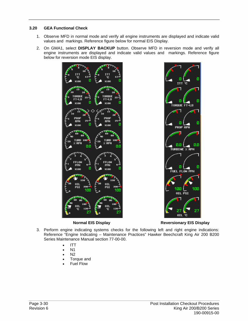
Page 3-30 Post Installation Checkout Procedures Revision 6 King Air 200/B200 Series 190-00915-00
3.20 GEA Functional Check
1. Observe MFD in normal mode and verify all engine instruments are displayed and indicate valid values and markings. Reference figure below for normal EIS Display.
2. On GMA1, select DISPLAY BACKUP button. Observe MFD in reversion mode and verify all engine instruments are displayed and indicate valid values and markings. Reference figure below for reversion mode EIS display.
Normal EIS Display Reversionary EIS Display
3. Perform engine indicating systems checks for the following left and right engine indications: Reference “Engine Indicating – Maintenance Practices” Hawker Beechcraft King Air 200 B200 Series Maintenance Manual section 77-00-00.
• ITT • N1 • N2 • Torque and • Fuel Flow
Post Installation Checkout Procedures Page 3-31 King Air 200/B200 Series Revision 6 190-00915-00
3.21 TAWS Functional Check
3.21.1 Functional Check for TAWS-B
1. From the MAP group, select the TAWS page on the MFD.
2. Verify that the title at the top of the page reads “MAP – TAWS-B”.
NOTE If TAWS has not been enabled, the title will read “MAP – TERRAIN PROXIMITY” or “MAP – TERRAIN”. Refer to 2.19 for TAWS-B enabling procedures.
3. Press the GCU MENU button and select “Test TAWS” from the pop-up menu.
4. After the TAWS test has completed, verify that “TAWS System Test Okay” is heard over the cockpit speaker.
5. Press the GCU MENU button again and select “Inhibit TAWS” from the pop-up menu and press ENT on the GCU. Verify “TAWS INHB “ is displayed on PFD1, PFD2 and MFD.
6. Press the GCU MENU button again and select “Enable TAWS” from the prop-up menu and press ENT on the GCU. Verify the “TAWS INHB” annunciation on the PFDs and MFD has extinguished.
7. With a GPS position acquired, shield or disconnect the GPS antennas to remove the GPS signal. Verify “No GPS Position” shows on the MFD and the “TAWS N/A” and “LOI” annunciations show on the PFDs.
8. Reconnect or remove the shield from the GPS antennas, and verify the MFD indication and PFD annunciations are removed once the GPS satellites are acquired.
9. Pull PFD1 PRI and PFD1 SEC circuit breakers. Re-power PFD1 in configuration mode, and use the PFD1 FMS knob to select the Audio Alert Configuration page.
10. Ensure cockpit speaker is selected ON. Use the PFD1 FMS knob to highlight each of the following messages then select PLAY. Verify each of the following audio messages are played:
Caution, Obstacle (2x) Terrain Ahead, Pull-Up (2x) Caution, Terrain (2x) Terrain Ahead (2x) Don’t Sink Too Low, Terrain Obstacle Ahead (2x) Terrain (2x); Pull-Up (2x) Obstacle Ahead, Pull-Up (2x) Sink Rate Obstacle (x2); Pull-Up (2x) Five Hundred Pull-Up
11. Pull the PFD1 PRI and PFD1 SEC circuit breakers, and re-power PFD1 in normal operating
mode.
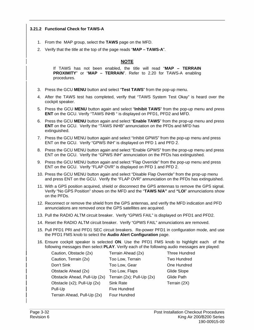
Page 3-32 Post Installation Checkout Procedures Revision 6 King Air 200/B200 Series 190-00915-00
3.21.2 Functional Check for TAWS-A
1. From the MAP group, select the TAWS page on the MFD.
2. Verify that the title at the top of the page reads “MAP – TAWS-A”.
NOTE If TAWS has not been enabled, the title will read “MAP – TERRAIN PROXIMITY” or “MAP – TERRAIN”. Refer to 2.20 for TAWS-A enabling procedures.
3. Press the GCU MENU button and select “Test TAWS” from the pop-up menu.
4. After the TAWS test has completed, verify that “TAWS System Test Okay” is heard over the cockpit speaker.
5. Press the GCU MENU button again and select “Inhibit TAWS” from the pop-up menu and press ENT on the GCU. Verify “TAWS INHB “ is displayed on PFD1, PFD2 and MFD.
6. Press the GCU MENU button again and select “Enable TAWS” from the prop-up menu and press ENT on the GCU. Verify the “TAWS INHB” annunciation on the PFDs and MFD has extinguished.
7. Press the GCU MENU button again and select “Inhibit GPWS” from the pop-up menu and press ENT on the GCU. Verify “GPWS INH” is displayed on PFD 1 and PFD 2.
8. Press the GCU MENU button again and select “Enable GPWS” from the prop-up menu and press ENT on the GCU. Verify the “GPWS INH” annunciation on the PFDs has extinguished.
9. Press the GCU MENU button again and select “Flap Override” from the pop-up menu and press ENT on the GCU. Verify “FLAP OVR” is displayed on PFD 1 and PFD 2.
10. Press the GCU MENU button again and select “Disable Flap Override” from the prop-up menu and press ENT on the GCU. Verify the “FLAP OVR” annunciation on the PFDs has extinguished.
11. With a GPS position acquired, shield or disconnect the GPS antennas to remove the GPS signal. Verify “No GPS Position” shows on the MFD and the “TAWS N/A” and “LOI” annunciations show on the PFDs.
12. Reconnect or remove the shield from the GPS antennas, and verify the MFD indication and PFD annunciations are removed once the GPS satellites are acquired.
13. Pull the RADIO ALTM circuit breaker. Verify “GPWS FAIL” is displayed on PFD1 and PFD2.
14. Reset the RADIO ALTM circuit breaker. Verify “GPWS FAIL” annunciations are removed.
15. Pull PFD1 PRI and PFD1 SEC circuit breakers. Re-power PFD1 in configuration mode, and use the PFD1 FMS knob to select the Audio Alert Configuration page.
16. Ensure cockpit speaker is selected ON. Use the PFD1 FMS knob to highlight each of the following messages then select PLAY. Verify each of the following audio messages are played:
Caution, Obstacle (2x) Terrain Ahead (2x) Three Hundred Caution, Terrain (2x) Too Low, Terrain Two Hundred Don’t Sink Too Low, Gear One Hundred Obstacle Ahead (2x) Too Low, Flaps Glide Slope Obstacle Ahead, Pull-Up (2x) Terrain (2x); Pull-Up (2x) Glide Path Obstacle (x2); Pull-Up (2x) Sink Rate Terrain (2X) Pull-Up Five Hundred Terrain Ahead, Pull-Up (2x) Four Hundred

Post Installation Checkout Procedures Page 3-33 King Air 200/B200 Series Revision 6 190-00915-00
17. Pull the PFD1 PRI and PFD1 SEC circuit breakers, and re-power PFD1 in normal operating mode.
NOTE The following steps require the movement of the flaps and landing gear. Ensure aircraft is safe for the operation of the flaps and landing gear before proceeding.
18. Place the airplane on jacks (Ref. Maintenance Manual Chapter 7-00-00) with the wheels clear of the ground.
19. Ensure all equipment and personnel are clear of the flaps and landing gear. Place the flaps and landing gear in the full down positions.
20. Using an air data test set connected to the pilot side pitot/static system, set an airspeed of at least 190 kts as displayed on PFD1.
21. After an alert advisory appears, press the softkey directly below the flashing ADVISORY.
22. Verify the “TAWS FLAP FAULT – Flaps detected in the LDG position” and “TAWS GEAR FAULT – Landing Gear detected in the DOWN position” messages are present.
23. Press the ALERTS softkey to close the alerts window.
24. Place the flaps and landing gear in the full up positions.
25. Press the ALERTS softkey again to open the alerts window.
26. Verify the “TAWS FLAP FAULT – Flaps detected in the LDG position” and “TAWS GEAR FAULT – Landing Gear detected in the DOWN position” messages not present.
27. Return air data test set to GROUND.
28. Place the landing gear in the down position and remove the aircraft from the jacks.

Page 3-34 Post Installation Checkout Procedures Revision 6 King Air 200/B200 Series 190-00915-00
3.22 FliteCharts Functional Check
NOTE This test is not required if ChartView is enabled.
1. On the MFD, select “AUX – System Status” page then select DBASE softkey. 2. Use the small FMS knob to scroll to CHART. 3. Verify “FliteCharts” is displayed in blue text adjacent to “CHART”. 4. Verify the FliteCharts database ‘REGION’, ‘CYCLE’ number, ‘EFFECTIVE’, ‘EXPIRES’, and
‘DISABLES’ dates of the subscription appear in blue text.
5. Deactivate the cursor and use the GCU large FMS knob to select the Navigation Map Page then press the SHW CHRT softkey.
6. Verify Terminal Chart is displayed and softkey selection advances to the following: • CHRT OPT • CHRT • INFO • DP • STAR • APR • WX • GO BACK
7. Press the CHRT OPT softkey and verify Terminal Chart is displayed and the softkeys advance to the following:
• ALL • FIT WDTH • FULL SCN • BACK
Post Installation Checkout Procedures Page 3-35 King Air 200/B200 Series Revision 6 190-00915-00
3.23 ChartView Functional Check
ChartView must be enabled using a ChartView Enable Card, as specified in 005-00421-03 “General Arrangement Drawing, King Air 200 B200” and a current ChartView database. Reference section 2.18 “ChartView Configuration” for enabling procedures.
NOTE The required ChartView databases are subscription-based and are to be procured by the aircraft owner directly from Jeppesen.
1. Select ‘AUX – System Status’ page for display and verify ChartView database cycle number is
displayed in blue text and ChartView database is current.
2. From the Navigation Map page, press the SHW CHRT softkey and verify airport chart is displayed and the following softkeys are displayed:
• CHRT OPT • CHRT • INFO • DP • STAR • APR • WX • NOTAM (grayed out) • GO BACK
3. Press CHRT OPT softkey and verify softkeys advance to the following level of softkeys: • ALL • HEADER (grayed out) • PLAN • PROFILE (grayed out) • MINIMUMS (grayed out) • FIT WDTH • FULL SCN • BACK
4. Return to the Navigation Map Page.
5. Press the GCU MENU key to display the PAGE MENU. Turn the GCU large FMS knob to scroll through the OPTIONS Menu to ‘Show Chart’. Press the GCU ENT key to display the chart and verify airport diagram is being displayed.
6. Press the GCU FMS knob to activate the cursor. Turn the GCU large FMS Knob to select the Airport Identifier Box.
7. Turn the GCU small and large FMS knob to enter the airport identifier for New Century airport (KIXD) then press the GCU ENT key to complete the airport selection.
8. Select the APR softkey. Turn the GCU large FMS Knob to select the Approach Box then turn the small FMS Knob to show the approach chart selection choices.
9. Turn either GCU FMS knob to scroll through the available charts and select a chart for viewing by pressing the GCU ENT key to complete the chart selection and verify the appropriate ChartView chart is displayed.
Page 3-36 Post Installation Checkout Procedures Revision 6 King Air 200/B200 Series 190-00915-00
3.24 SafeTaxi Functional Check
The maximum map ranges for enhanced detail are configurable by the flight crew. When zoomed in close enough to show the airport detail, the map reveals runways with numbers, taxiways with identifying letters/numbers, and airport landmarks including ramps, buildings, control towers, and other prominent features. Resolution is greater at lower map ranges. When the aircraft location is within the screen boundary, including within SafeTaxi ranges, an airplane symbol is shown on any of the navigation map views for enhanced position awareness. Any map page that displays the navigation view can also show the SafeTaxi airport layout within the maximum configured range. The following is a list of pages where the SafeTaxi feature can be seen:
• Navigation Map Page • Inset map • Weather Datalink Page • Airport Information Page • Intersection Information Page • NDB Information Page • VOR Information Page • User Waypoint Information Page • Trip Planning Page • Nearest Pages
1. Select the AUX – System Status page and verify current revision levels are displayed for the following:
• REGION • VERSION • CYCLE • EFFECTIVE • EXPIRES
2. Select Navigation Map page.
3. On the GCU, press MENU. With Map Setup highlighted, press ENT on the GCU. Rotate the small GCU FMS knob to select the Aviation group and press the ENT key on GCU.
4. Turn the GCU large FMS Knob to scroll through the Aviation Group options to ‘SAFETAXI’.
5. Turn the GCU small FMS Knob to display the range of distances.
6. Turn either GCU FMS Knob to select 5000ft as the distance for maximum SafeTaxi display range then press the GCU ENT key to complete the selection.
7. Using the GCU range knob, select a range of 5000ft or less. Verify SafeTaxi display represents the current aircraft location and the airport layout.
Post Installation Checkout Procedures Page 3-37 King Air 200/B200 Series Revision 6 190-00915-00
3.25 GWX 68 Weather Radar Check
CAUTION! Before energizing the equipment, be sure microwave radiation safety precautions including both fuel and personnel safety considerations have been observed. These include clearing all personnel to an area beyond the maximum permissible exposure level (MPEL) boundary. The MPEL for the GWX 68 is 11 feet.
1. On the GCU, turn the large FMS knob to select the Map Page Group then turn the small FMS
knob to select the Weather Radar page.
2. Select the MODE Softkey.
3. Select the STANDBY softkey to initiate the one minute warm-up period. Verify, the radar enters the standby mode after the warm-up is complete.
4. Press the GCU FMS knob to activate the cursor in the TILT field then turn the small FMS knob to select the desired antenna tilt angle. Press the GCU ENT key. Press the GCU FMS knob to remove the cursor.
5. Select the WEATHER softkey. After reading the CAUTION, press YES to continue. Select vertical profile mode.
6. Select the TILT softkey to activate the cursor in the TILT field and display the Tilt Line. (If the Tilt Line is not displayed, press the GCU MENU key and turn the large FMS knob to select ‘Show Tilt Line’). Press the ENT key.
7. On the GCU, turn the small FMS Knob to adjust the antenna tilt angle then select the GAIN Softkey to activate the cursor in the ‘GAIN’ field.
8. On the GCU, turn the small FMS Knob to adjust the gain for the desirable level. Verify the gain setting is visible in the gain field as a movable horizontal bar in a flashing box and the line pointer is a reference depicting the calibrated position. Press the FMS Knob to remove the cursor.
9. On the GCU, select the GAIN Softkey again to recalibrate the gain. Verify ‘CALIBRATED’ is displayed in the ‘GAIN’ field.
10. Select the STAB ON Softkey to activate antenna stabilization or select the STAB OFF softkey to deactivate. Verify the current stabilization condition is shown in the upper right of the weather radar display.

Page 3-38 Post Installation Checkout Procedures Revision 6 King Air 200/B200 Series 190-00915-00
This page intentionally left blank
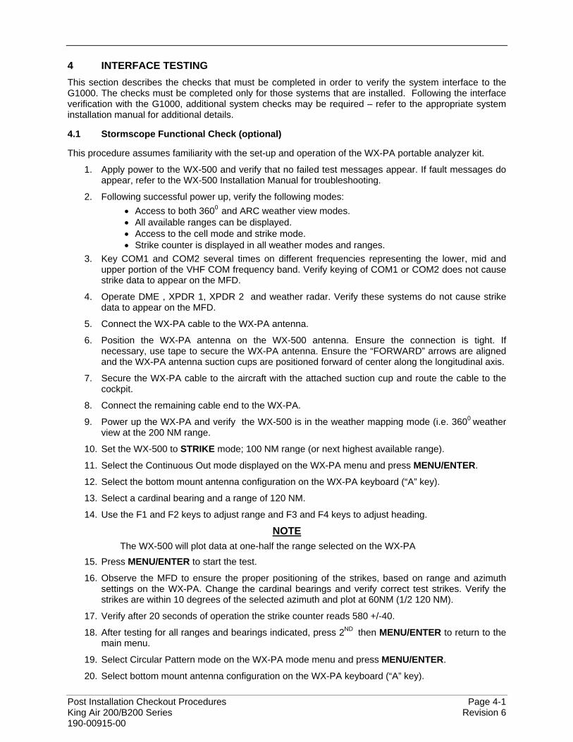
Post Installation Checkout Procedures Page 4-1 King Air 200/B200 Series Revision 6 190-00915-00
4 INTERFACE TESTING This section describes the checks that must be completed in order to verify the system interface to the G1000. The checks must be completed only for those systems that are installed. Following the interface verification with the G1000, additional system checks may be required – refer to the appropriate system installation manual for additional details.
4.1 Stormscope Functional Check (optional)
This procedure assumes familiarity with the set-up and operation of the WX-PA portable analyzer kit.
1. Apply power to the WX-500 and verify that no failed test messages appear. If fault messages do appear, refer to the WX-500 Installation Manual for troubleshooting.
2. Following successful power up, verify the following modes: • Access to both 3600 and ARC weather view modes. • All available ranges can be displayed. • Access to the cell mode and strike mode. • Strike counter is displayed in all weather modes and ranges.
3. Key COM1 and COM2 several times on different frequencies representing the lower, mid and upper portion of the VHF COM frequency band. Verify keying of COM1 or COM2 does not cause strike data to appear on the MFD.
4. Operate DME , XPDR 1, XPDR 2 and weather radar. Verify these systems do not cause strike data to appear on the MFD.
5. Connect the WX-PA cable to the WX-PA antenna.
6. Position the WX-PA antenna on the WX-500 antenna. Ensure the connection is tight. If necessary, use tape to secure the WX-PA antenna. Ensure the “FORWARD” arrows are aligned and the WX-PA antenna suction cups are positioned forward of center along the longitudinal axis.
7. Secure the WX-PA cable to the aircraft with the attached suction cup and route the cable to the cockpit.
8. Connect the remaining cable end to the WX-PA.
9. Power up the WX-PA and verify the WX-500 is in the weather mapping mode (i.e. 3600 weather view at the 200 NM range.
10. Set the WX-500 to STRIKE mode; 100 NM range (or next highest available range).
11. Select the Continuous Out mode displayed on the WX-PA menu and press MENU/ENTER.
12. Select the bottom mount antenna configuration on the WX-PA keyboard (“A” key).
13. Select a cardinal bearing and a range of 120 NM.
14. Use the F1 and F2 keys to adjust range and F3 and F4 keys to adjust heading.
NOTE The WX-500 will plot data at one-half the range selected on the WX-PA
15. Press MENU/ENTER to start the test.
16. Observe the MFD to ensure the proper positioning of the strikes, based on range and azimuth settings on the WX-PA. Change the cardinal bearings and verify correct test strikes. Verify the strikes are within 10 degrees of the selected azimuth and plot at 60NM (1/2 120 NM).
17. Verify after 20 seconds of operation the strike counter reads 580 +/-40.
18. After testing for all ranges and bearings indicated, press 2ND then MENU/ENTER to return to the main menu.
19. Select Circular Pattern mode on the WX-PA mode menu and press MENU/ENTER.
20. Select bottom mount antenna configuration on the WX-PA keyboard (“A” key).
Page 4-2 Post Installation Checkout Procedures Revision 6 King Air 200/B200 Series 190-00915-00
NOTE The MFD should be set at 100 NM (or next highest available range) on the 360 degree weather screen and in strike mode.
21. Use the F1 and F2 keys to select 120 NM range and press MENU/ENTER to start the test. Verify the WX-500 plots discharge points at approximately 60 NM.
22. Observe the MFD to ensure the proper positioning of the test strikes. Verify the strikes are within 10 degrees of the 30 degree azimuth increment and within 12 NM of 60 NM,
23. When complete, set WX-PA for 55 NM, set the MFD for 50 NM (or the next highest available range) and repeat test.
24. On the MFD, verify the sensor plots points just outside of 25 NM and the strikes are within 10 degrees of the 30 degree azimuth and within 5 NM of 27.5 NM.
25. Repeat above setting the MFD for 25 NM (or the next highest available range) and the WX-PA for 15 NM.
26. On the MFD, verify the positioning of test strikes within are within 10 degrees of azimuth and within 2 NM of 7.5 NM.

Post Installation Checkout Procedures Page 4-3 King Air 200/B200 Series Revision 6 190-00915-00
4.2 Traffic System Functional Check (optional)
1. Select the TRAFFIC MAP page on the MFD.
2. Verify that the STANDBY, OPERATE, TEST and ALT MODE softkeys are available on the bottom of the display. Verify that an operating mode; STANDBY, OPERATE, or TEST (not FAIL) is displayed in the upper left corner of the traffic map. Verify that NO DATA is not displayed in yellow in the center of the display over the aircraft symbol.
NOTE If the ALT MODE softkey is not displayed, the G1000 has not been properly configured for the traffic system. Reference section 2.14 “Traffic System Configuration Option to enable the traffic system.
3. Press the OPERATE softkey and verify that OPERATING is displayed in the upper left corner of
the traffic map.
4. Press the STANDBY softkey and verify that STANDBY is displayed in the upper left corner of the traffic map.
5. Press the TEST softkey and verify that TEST is displayed in the upper left corner of the traffic map and a traffic test pattern is displayed. Upon completion of the test, verify that “TAS SYSTEM TEST OK” is heard over the cockpit speaker.
NOTE This annunciated traffic system test message may be different from the traffic system installed on subject aircraft.
6. Open the TRAFFIC circuit breaker on the copilot circuit breaker panel. On the MFD, verify that
NO DATA is displayed in yellow after several seconds.
7. Close the TRAFFIC ALERT circuit breaker on the avionics circuit breaker panel and verify that NO DATA is removed after several seconds.
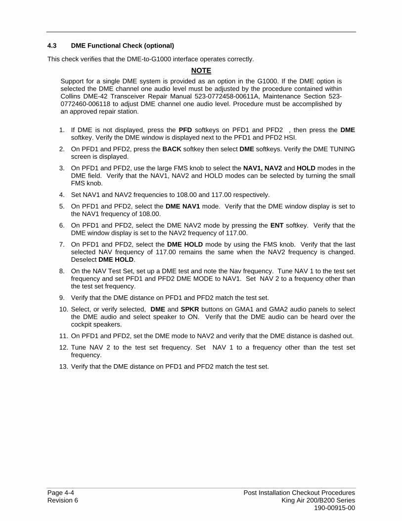
Page 4-4 Post Installation Checkout Procedures Revision 6 King Air 200/B200 Series 190-00915-00
4.3 DME Functional Check (optional)
This check verifies that the DME-to-G1000 interface operates correctly.
NOTE Support for a single DME system is provided as an option in the G1000. If the DME option is selected the DME channel one audio level must be adjusted by the procedure contained within Collins DME-42 Transceiver Repair Manual 523-0772458-00611A, Maintenance Section 523-0772460-006118 to adjust DME channel one audio level. Procedure must be accomplished by an approved repair station.
1. If DME is not displayed, press the PFD softkeys on PFD1 and PFD2 , then press the DME
softkey. Verify the DME window is displayed next to the PFD1 and PFD2 HSI.
2. On PFD1 and PFD2, press the BACK softkey then select DME softkeys. Verify the DME TUNING screen is displayed.
3. On PFD1 and PFD2, use the large FMS knob to select the NAV1, NAV2 and HOLD modes in the DME field. Verify that the NAV1, NAV2 and HOLD modes can be selected by turning the small FMS knob.
4. Set NAV1 and NAV2 frequencies to 108.00 and 117.00 respectively.
5. On PFD1 and PFD2, select the DME NAV1 mode. Verify that the DME window display is set to the NAV1 frequency of 108.00.
6. On PFD1 and PFD2, select the DME NAV2 mode by pressing the ENT softkey. Verify that the DME window display is set to the NAV2 frequency of 117.00.
7. On PFD1 and PFD2, select the DME HOLD mode by using the FMS knob. Verify that the last selected NAV frequency of 117.00 remains the same when the NAV2 frequency is changed. Deselect DME HOLD.
8. On the NAV Test Set, set up a DME test and note the Nav frequency. Tune NAV 1 to the test set frequency and set PFD1 and PFD2 DME MODE to NAV1. Set NAV 2 to a frequency other than the test set frequency.
9. Verify that the DME distance on PFD1 and PFD2 match the test set.
10. Select, or verify selected, DME and SPKR buttons on GMA1 and GMA2 audio panels to select the DME audio and select speaker to ON. Verify that the DME audio can be heard over the cockpit speakers.
11. On PFD1 and PFD2, set the DME mode to NAV2 and verify that the DME distance is dashed out.
12. Tune NAV 2 to the test set frequency. Set NAV 1 to a frequency other than the test set frequency.
13. Verify that the DME distance on PFD1 and PFD2 match the test set.
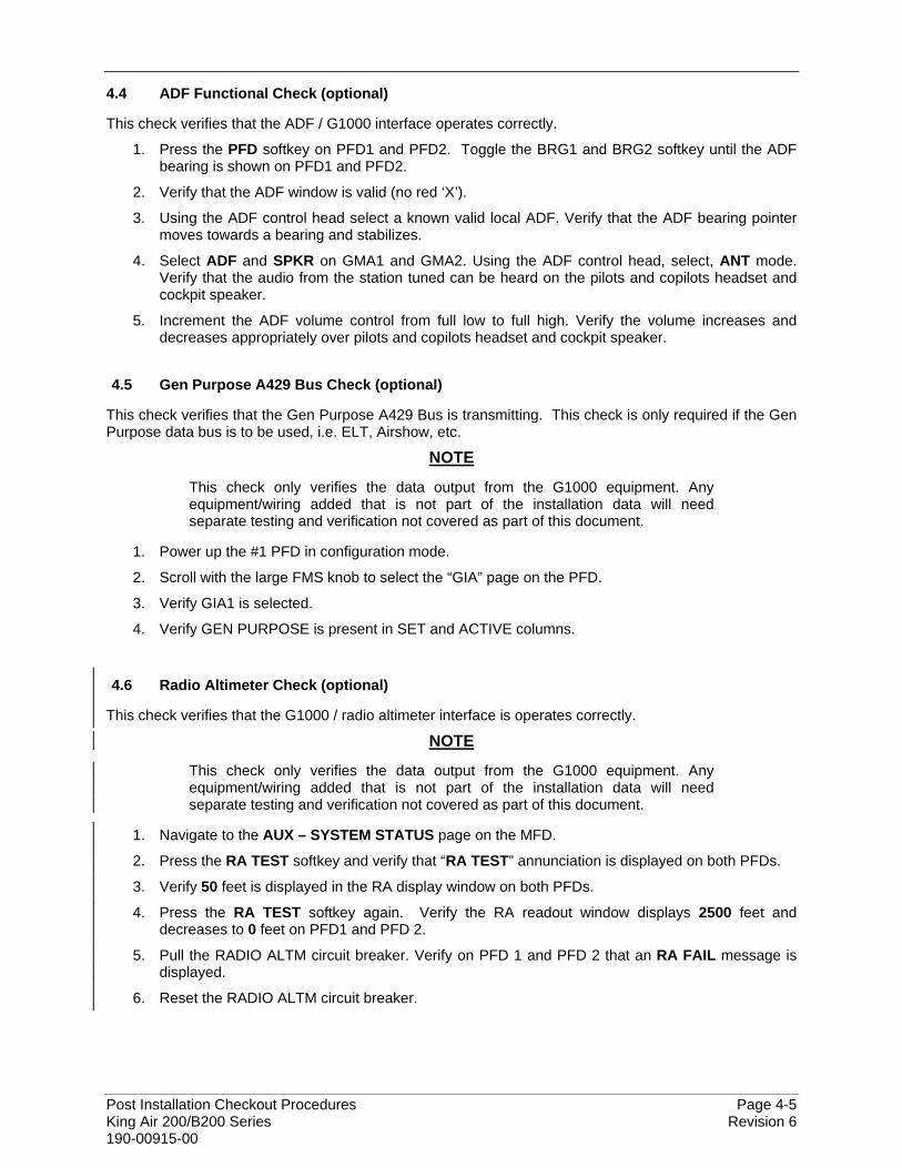
Post Installation Checkout Procedures Page 4-5 King Air 200/B200 Series Revision 6 190-00915-00
4.4 ADF Functional Check (optional)
This check verifies that the ADF / G1000 interface operates correctly.
1. Press the PFD softkey on PFD1 and PFD2. Toggle the BRG1 and BRG2 softkey until the ADF bearing is shown on PFD1 and PFD2.
2. Verify that the ADF window is valid (no red ‘X’).
3. Using the ADF control head select a known valid local ADF. Verify that the ADF bearing pointer moves towards a bearing and stabilizes.
4. Select ADF and SPKR on GMA1 and GMA2. Using the ADF control head, select, ANT mode. Verify that the audio from the station tuned can be heard on the pilots and copilots headset and cockpit speaker.
5. Increment the ADF volume control from full low to full high. Verify the volume increases and decreases appropriately over pilots and copilots headset and cockpit speaker.
4.5 Gen Purpose A429 Bus Check (optional)
This check verifies that the Gen Purpose A429 Bus is transmitting. This check is only required if the Gen Purpose data bus is to be used, i.e. ELT, Airshow, etc.
NOTE
This check only verifies the data output from the G1000 equipment. Any equipment/wiring added that is not part of the installation data will need separate testing and verification not covered as part of this document.
1. Power up the #1 PFD in configuration mode.
2. Scroll with the large FMS knob to select the “GIA” page on the PFD.
3. Verify GIA1 is selected.
4. Verify GEN PURPOSE is present in SET and ACTIVE columns.
4.6 Radio Altimeter Check (optional)
This check verifies that the G1000 / radio altimeter interface is operates correctly.
NOTE
This check only verifies the data output from the G1000 equipment. Any equipment/wiring added that is not part of the installation data will need separate testing and verification not covered as part of this document.
1. Navigate to the AUX – SYSTEM STATUS page on the MFD.
2. Press the RA TEST softkey and verify that “RA TEST” annunciation is displayed on both PFDs.
3. Verify 50 feet is displayed in the RA display window on both PFDs.
4. Press the RA TEST softkey again. Verify the RA readout window displays 2500 feet and decreases to 0 feet on PFD1 and PFD 2.
5. Pull the RADIO ALTM circuit breaker. Verify on PFD 1 and PFD 2 that an RA FAIL message is displayed.
6. Reset the RADIO ALTM circuit breaker.

Page 4-6 Post Installation Checkout Procedures Revision 6 King Air 200/B200 Series 190-00915-00
This page intentionally left blank
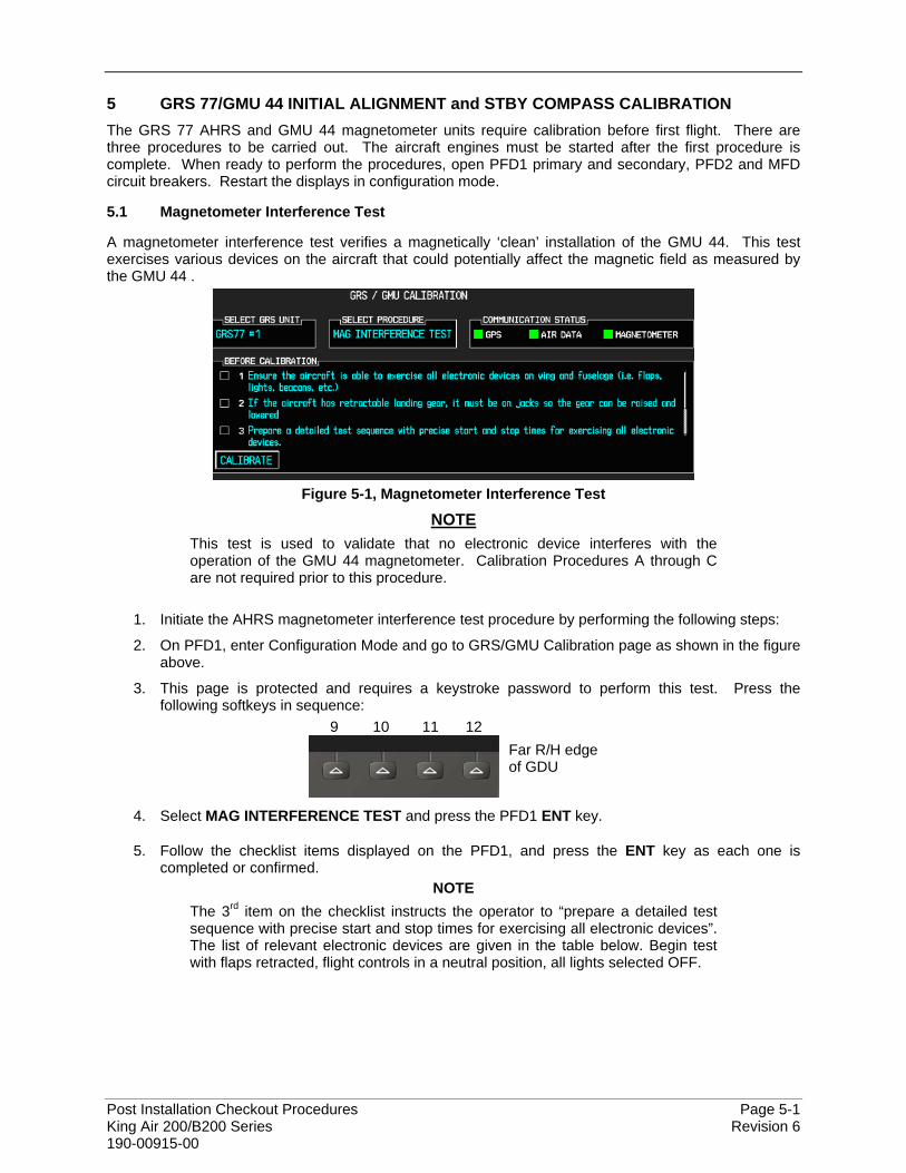
Post Installation Checkout Procedures Page 5-1 King Air 200/B200 Series Revision 6 190-00915-00
5 GRS 77/GMU 44 INITIAL ALIGNMENT and STBY COMPASS CALIBRATION The GRS 77 AHRS and GMU 44 magnetometer units require calibration before first flight. There are three procedures to be carried out. The aircraft engines must be started after the first procedure is complete. When ready to perform the procedures, open PFD1 primary and secondary, PFD2 and MFD circuit breakers. Restart the displays in configuration mode.
5.1 Magnetometer Interference Test
A magnetometer interference test verifies a magnetically ‘clean’ installation of the GMU 44. This test exercises various devices on the aircraft that could potentially affect the magnetic field as measured by the GMU 44 .
Figure 5-1, Magnetometer Interference Test
NOTE This test is used to validate that no electronic device interferes with the operation of the GMU 44 magnetometer. Calibration Procedures A through C are not required prior to this procedure.
1. Initiate the AHRS magnetometer interference test procedure by performing the following steps:
2. On PFD1, enter Configuration Mode and go to GRS/GMU Calibration page as shown in the figure above.
3. This page is protected and requires a keystroke password to perform this test. Press the following softkeys in sequence:
9 10 11 12 Far R/H edge of GDU
4. Select MAG INTERFERENCE TEST and press the PFD1 ENT key.
5. Follow the checklist items displayed on the PFD1, and press the ENT key as each one is completed or confirmed.
NOTE The 3rd item on the checklist instructs the operator to “prepare a detailed test sequence with precise start and stop times for exercising all electronic devices”. The list of relevant electronic devices are given in the table below. Begin test with flaps retracted, flight controls in a neutral position, all lights selected OFF.
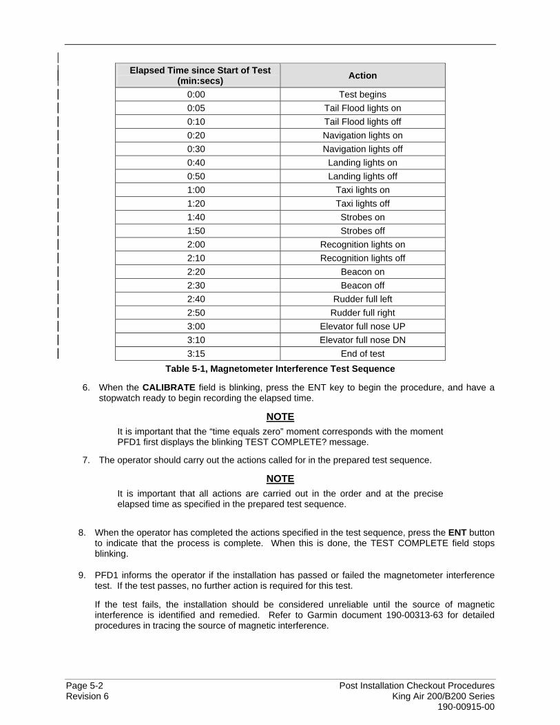
Page 5-2 Post Installation Checkout Procedures Revision 6 King Air 200/B200 Series 190-00915-00
Elapsed Time since Start of Test
(min:secs) Action
0:00 Test begins 0:05 Tail Flood lights on 0:10 Tail Flood lights off 0:20 Navigation lights on 0:30 Navigation lights off 0:40 Landing lights on 0:50 Landing lights off 1:00 Taxi lights on 1:20 Taxi lights off 1:40 Strobes on 1:50 Strobes off 2:00 Recognition lights on 2:10 Recognition lights off 2:20 Beacon on 2:30 Beacon off 2:40 Rudder full left 2:50 Rudder full right 3:00 Elevator full nose UP 3:10 Elevator full nose DN 3:15 End of test
Table 5-1, Magnetometer Interference Test Sequence
6. When the CALIBRATE field is blinking, press the ENT key to begin the procedure, and have a stopwatch ready to begin recording the elapsed time.
NOTE It is important that the “time equals zero” moment corresponds with the moment PFD1 first displays the blinking TEST COMPLETE? message.
7. The operator should carry out the actions called for in the prepared test sequence.
NOTE It is important that all actions are carried out in the order and at the precise elapsed time as specified in the prepared test sequence.
8. When the operator has completed the actions specified in the test sequence, press the ENT button to indicate that the process is complete. When this is done, the TEST COMPLETE field stops blinking.
9. PFD1 informs the operator if the installation has passed or failed the magnetometer interference test. If the test passes, no further action is required for this test.
If the test fails, the installation should be considered unreliable until the source of magnetic interference is identified and remedied. Refer to Garmin document 190-00313-63 for detailed procedures in tracing the source of magnetic interference.
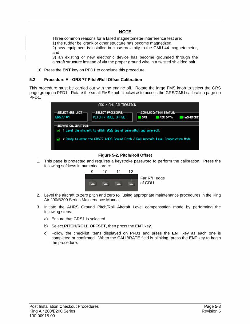
Post Installation Checkout Procedures Page 5-3 King Air 200/B200 Series Revision 6 190-00915-00
NOTE
Three common reasons for a failed magnetometer interference test are: 1) the rudder bellcrank or other structure has become magnetized, 2) new equipment is installed in close proximity to the GMU 44 magnetometer, and 3) an existing or new electronic device has become grounded through the aircraft structure instead of via the proper ground wire in a twisted shielded pair.
10. Press the ENT key on PFD1 to conclude this procedure.
5.2 Procedure A - GRS 77 Pitch/Roll Offset Calibration
This procedure must be carried out with the engine off. Rotate the large FMS knob to select the GRS page group on PFD1. Rotate the small FMS knob clockwise to access the GRS/GMU calibration page on PFD1.
Figure 5-2, Pitch/Roll Offset
1. This page is protected and requires a keystroke password to perform the calibration. Press the following softkeys in numerical order:
9 10 11 12 Far R/H edge of GDU
2. Level the aircraft to zero pitch and zero roll using appropriate maintenance procedures in the King Air 200/B200 Series Maintenance Manual.
3. Initiate the AHRS Ground Pitch/Roll Aircraft Level compensation mode by performing the following steps:
a) Ensure that GRS1 is selected.
b) Select PITCH/ROLL OFFSET, then press the ENT key.
c) Follow the checklist items displayed on PFD1 and press the ENT key as each one is completed or confirmed. When the CALIBRATE field is blinking, press the ENT key to begin the procedure.
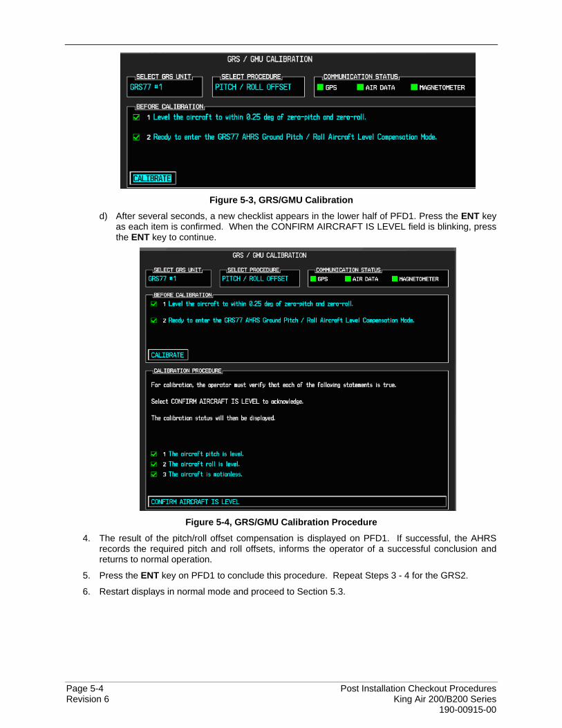
Page 5-4 Post Installation Checkout Procedures Revision 6 King Air 200/B200 Series 190-00915-00
Figure 5-3, GRS/GMU Calibration
d) After several seconds, a new checklist appears in the lower half of PFD1. Press the ENT key as each item is confirmed. When the CONFIRM AIRCRAFT IS LEVEL field is blinking, press the ENT key to continue.
Figure 5-4, GRS/GMU Calibration Procedure
4. The result of the pitch/roll offset compensation is displayed on PFD1. If successful, the AHRS records the required pitch and roll offsets, informs the operator of a successful conclusion and returns to normal operation.
5. Press the ENT key on PFD1 to conclude this procedure. Repeat Steps 3 - 4 for the GRS2.
6. Restart displays in normal mode and proceed to Section 5.3.
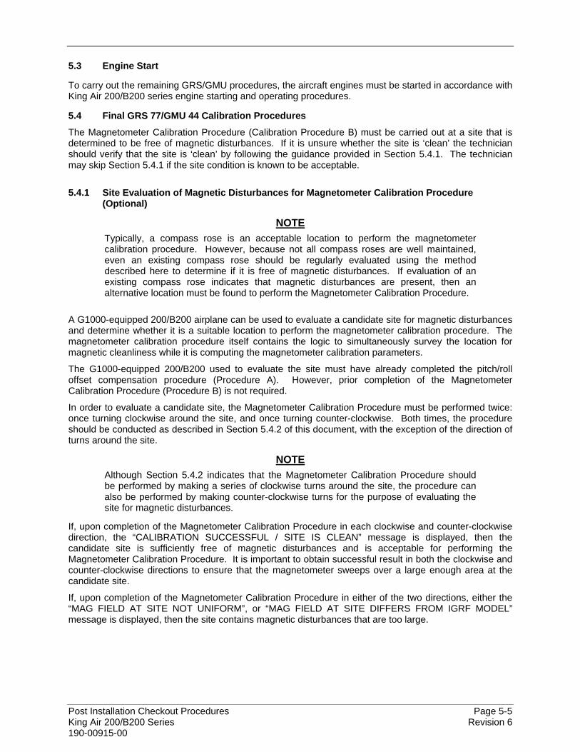
Post Installation Checkout Procedures Page 5-5 King Air 200/B200 Series Revision 6 190-00915-00
5.3 Engine Start
To carry out the remaining GRS/GMU procedures, the aircraft engines must be started in accordance with King Air 200/B200 series engine starting and operating procedures.
5.4 Final GRS 77/GMU 44 Calibration Procedures
The Magnetometer Calibration Procedure (Calibration Procedure B) must be carried out at a site that is determined to be free of magnetic disturbances. If it is unsure whether the site is ‘clean’ the technician should verify that the site is ‘clean’ by following the guidance provided in Section 5.4.1. The technician may skip Section 5.4.1 if the site condition is known to be acceptable.
5.4.1 Site Evaluation of Magnetic Disturbances for Magnetometer Calibration Procedure (Optional)
NOTE Typically, a compass rose is an acceptable location to perform the magnetometer calibration procedure. However, because not all compass roses are well maintained, even an existing compass rose should be regularly evaluated using the method described here to determine if it is free of magnetic disturbances. If evaluation of an existing compass rose indicates that magnetic disturbances are present, then an alternative location must be found to perform the Magnetometer Calibration Procedure.
A G1000-equipped 200/B200 airplane can be used to evaluate a candidate site for magnetic disturbances and determine whether it is a suitable location to perform the magnetometer calibration procedure. The magnetometer calibration procedure itself contains the logic to simultaneously survey the location for magnetic cleanliness while it is computing the magnetometer calibration parameters.
The G1000-equipped 200/B200 used to evaluate the site must have already completed the pitch/roll offset compensation procedure (Procedure A). However, prior completion of the Magnetometer Calibration Procedure (Procedure B) is not required.
In order to evaluate a candidate site, the Magnetometer Calibration Procedure must be performed twice: once turning clockwise around the site, and once turning counter-clockwise. Both times, the procedure should be conducted as described in Section 5.4.2 of this document, with the exception of the direction of turns around the site.
NOTE Although Section 5.4.2 indicates that the Magnetometer Calibration Procedure should be performed by making a series of clockwise turns around the site, the procedure can also be performed by making counter-clockwise turns for the purpose of evaluating the site for magnetic disturbances.
If, upon completion of the Magnetometer Calibration Procedure in each clockwise and counter-clockwise direction, the “CALIBRATION SUCCESSFUL / SITE IS CLEAN” message is displayed, then the candidate site is sufficiently free of magnetic disturbances and is acceptable for performing the Magnetometer Calibration Procedure. It is important to obtain successful result in both the clockwise and counter-clockwise directions to ensure that the magnetometer sweeps over a large enough area at the candidate site.
If, upon completion of the Magnetometer Calibration Procedure in either of the two directions, either the “MAG FIELD AT SITE NOT UNIFORM”, or “MAG FIELD AT SITE DIFFERS FROM IGRF MODEL” message is displayed, then the site contains magnetic disturbances that are too large.
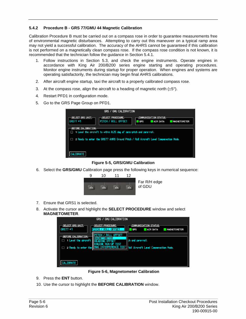
Page 5-6 Post Installation Checkout Procedures Revision 6 King Air 200/B200 Series 190-00915-00
5.4.2 Procedure B - GRS 77/GMU 44 Magnetic Calibration
Calibration Procedure B must be carried out on a compass rose in order to guarantee measurements free of environmental magnetic disturbances. Attempting to carry out this maneuver on a typical ramp area may not yield a successful calibration. The accuracy of the AHRS cannot be guaranteed if this calibration is not performed on a magnetically clean compass rose. If the compass rose condition is not known, it is recommended that the technician follow the guidance in Section 5.4.1.
1. Follow instructions in Section 5.3, and check the engine instruments. Operate engines in accordance with King Air 200/B200 series engine starting and operating procedures. Monitor engine instruments during startup for proper operation. When engines and systems are operating satisfactorily, the technician may begin final AHRS calibrations.
2. After aircraft engine startup, taxi the aircraft to a properly calibrated compass rose.
3. At the compass rose, align the aircraft to a heading of magnetic north (±5°).
4. Restart PFD1 in configuration mode.
5. Go to the GRS Page Group on PFD1.
Figure 5-5, GRS/GMU Calibration
6. Select the GRS/GMU Calibration page press the following keys in numerical sequence: 9 10 11 12
Far R/H edge of GDU
7. Ensure that GRS1 is selected. 8. Activate the cursor and highlight the SELECT PROCEDURE window and select
MAGNETOMETER.
Figure 5-6, Magnetometer Calibration
9. Press the ENT button. 10. Use the cursor to highlight the BEFORE CALIBRATION window.
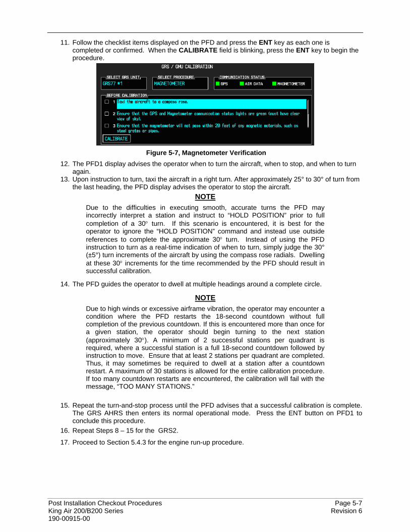
Post Installation Checkout Procedures Page 5-7 King Air 200/B200 Series Revision 6 190-00915-00
11. Follow the checklist items displayed on the PFD and press the ENT key as each one is completed or confirmed. When the CALIBRATE field is blinking, press the ENT key to begin the procedure.
Figure 5-7, Magnetometer Verification
12. The PFD1 display advises the operator when to turn the aircraft, when to stop, and when to turn again.
13. Upon instruction to turn, taxi the aircraft in a right turn. After approximately 25° to 30° of turn from the last heading, the PFD display advises the operator to stop the aircraft.
NOTE Due to the difficulties in executing smooth, accurate turns the PFD may incorrectly interpret a station and instruct to “HOLD POSITION” prior to full completion of a 30° turn. If this scenario is encountered, it is best for the operator to ignore the “HOLD POSITION” command and instead use outside references to complete the approximate 30° turn. Instead of using the PFD instruction to turn as a real-time indication of when to turn, simply judge the 30° (±5°) turn increments of the aircraft by using the compass rose radials. Dwelling at these 30° increments for the time recommended by the PFD should result in successful calibration.
14. The PFD guides the operator to dwell at multiple headings around a complete circle.
NOTE Due to high winds or excessive airframe vibration, the operator may encounter a condition where the PFD restarts the 18-second countdown without full completion of the previous countdown. If this is encountered more than once for a given station, the operator should begin turning to the next station (approximately 30°). A minimum of 2 successful stations per quadrant is required, where a successful station is a full 18-second countdown followed by instruction to move. Ensure that at least 2 stations per quadrant are completed. Thus, it may sometimes be required to dwell at a station after a countdown restart. A maximum of 30 stations is allowed for the entire calibration procedure. If too many countdown restarts are encountered, the calibration will fail with the message, “TOO MANY STATIONS.”
15. Repeat the turn-and-stop process until the PFD advises that a successful calibration is complete.
The GRS AHRS then enters its normal operational mode. Press the ENT button on PFD1 to conclude this procedure.
16. Repeat Steps 8 – 15 for the GRS2.
17. Proceed to Section 5.4.3 for the engine run-up procedure.
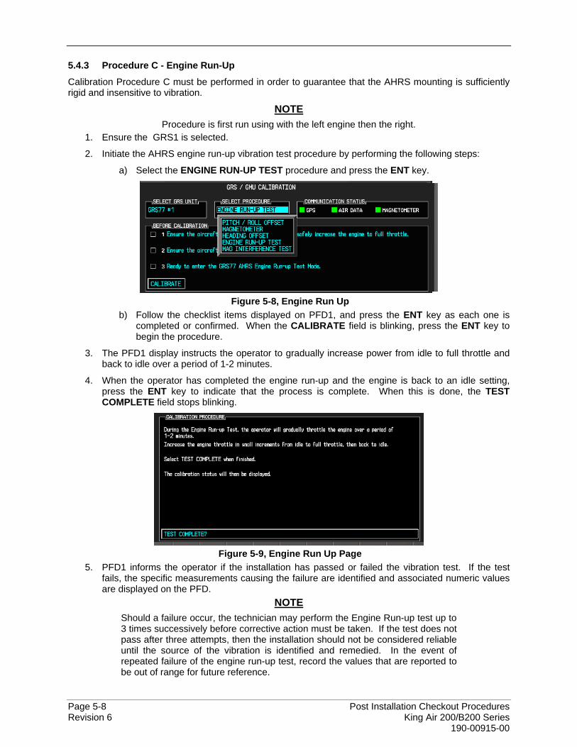
Page 5-8 Post Installation Checkout Procedures Revision 6 King Air 200/B200 Series 190-00915-00
5.4.3 Procedure C - Engine Run-Up
Calibration Procedure C must be performed in order to guarantee that the AHRS mounting is sufficiently rigid and insensitive to vibration.
NOTE Procedure is first run using with the left engine then the right.
1. Ensure the GRS1 is selected.
2. Initiate the AHRS engine run-up vibration test procedure by performing the following steps:
a) Select the ENGINE RUN-UP TEST procedure and press the ENT key.
Figure 5-8, Engine Run Up
b) Follow the checklist items displayed on PFD1, and press the ENT key as each one is completed or confirmed. When the CALIBRATE field is blinking, press the ENT key to begin the procedure.
3. The PFD1 display instructs the operator to gradually increase power from idle to full throttle and back to idle over a period of 1-2 minutes.
4. When the operator has completed the engine run-up and the engine is back to an idle setting, press the ENT key to indicate that the process is complete. When this is done, the TEST COMPLETE field stops blinking.
Figure 5-9, Engine Run Up Page
5. PFD1 informs the operator if the installation has passed or failed the vibration test. If the test fails, the specific measurements causing the failure are identified and associated numeric values are displayed on the PFD.
NOTE Should a failure occur, the technician may perform the Engine Run-up test up to 3 times successively before corrective action must be taken. If the test does not pass after three attempts, then the installation should not be considered reliable until the source of the vibration is identified and remedied. In the event of repeated failure of the engine run-up test, record the values that are reported to be out of range for future reference.

Post Installation Checkout Procedures Page 5-9 King Air 200/B200 Series Revision 6 190-00915-00
The following are potential causes for failure of the engine run-up test: • Vibration motion of GRS77 and/or GMU44 caused by neighboring equipment and/or
supports. • Mounting screws and other hardware for GRS77 and/or GMU44 not firmly attached. • GRS77 connector not firmly attached to unit. • Cabling leading to GRS77 or GMU44 not firmly secured to supporting structure. • An engine / propeller that is significantly out of balance.
6. Press the ENT key on PFD1 to conclude this procedure.
7. Repeat Steps 2 – 7 for GRS2.
8. Proceed to Section 5.4.4.
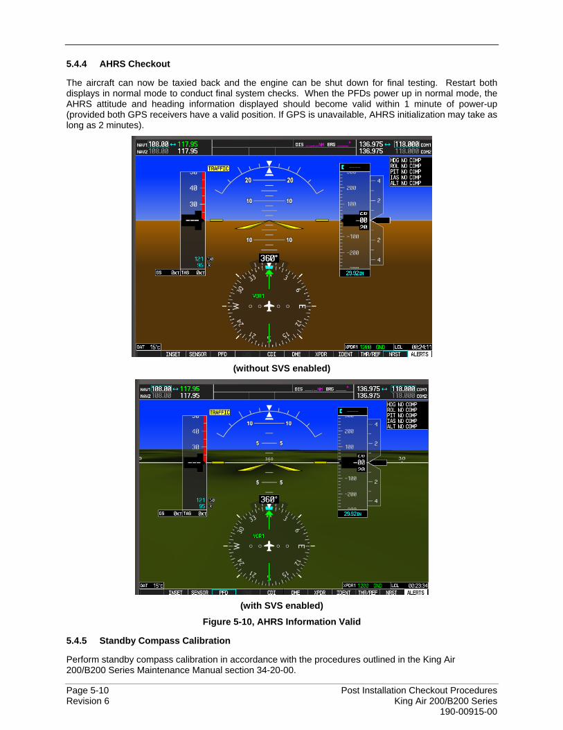
Page 5-10 Post Installation Checkout Procedures Revision 6 King Air 200/B200 Series 190-00915-00
5.4.4 AHRS Checkout
The aircraft can now be taxied back and the engine can be shut down for final testing. Restart both displays in normal mode to conduct final system checks. When the PFDs power up in normal mode, the AHRS attitude and heading information displayed should become valid within 1 minute of power-up (provided both GPS receivers have a valid position. If GPS is unavailable, AHRS initialization may take as long as 2 minutes).
(without SVS enabled)
(with SVS enabled)
Figure 5-10, AHRS Information Valid
5.4.5 Standby Compass Calibration
Perform standby compass calibration in accordance with the procedures outlined in the King Air 200/B200 Series Maintenance Manual section 34-20-00.
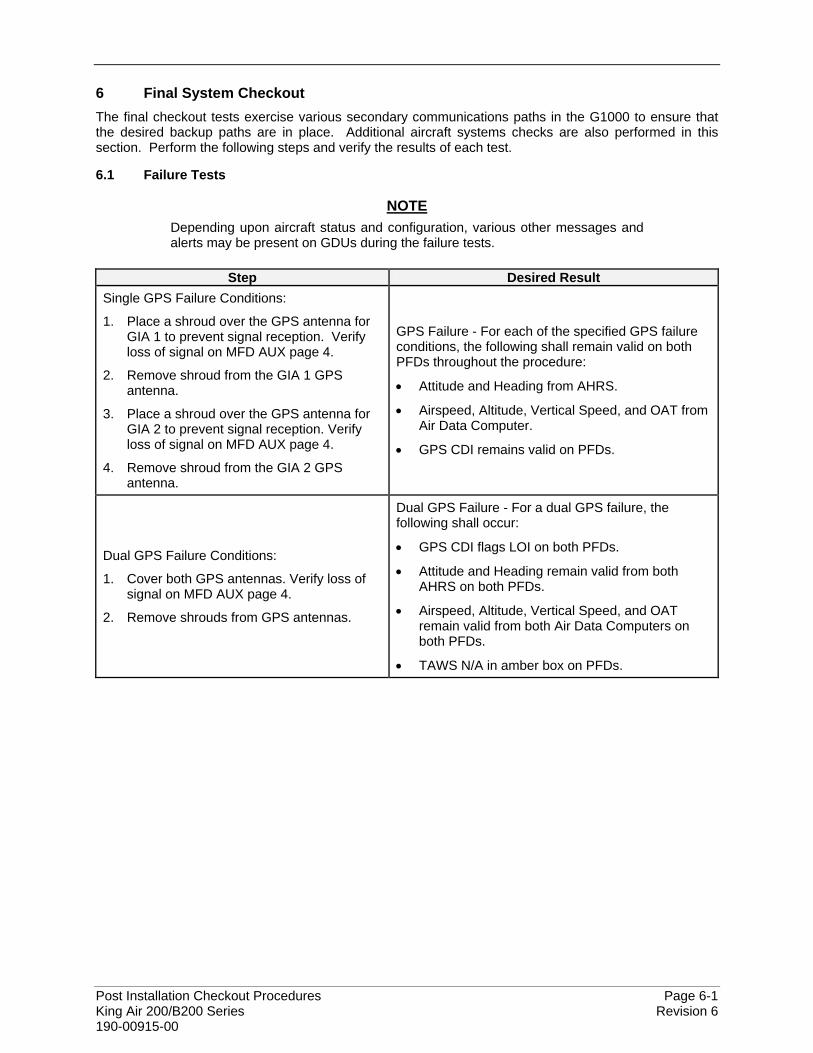
Post Installation Checkout Procedures Page 6-1 King Air 200/B200 Series Revision 6 190-00915-00
6 Final System Checkout The final checkout tests exercise various secondary communications paths in the G1000 to ensure that the desired backup paths are in place. Additional aircraft systems checks are also performed in this section. Perform the following steps and verify the results of each test.
6.1 Failure Tests
NOTE Depending upon aircraft status and configuration, various other messages and alerts may be present on GDUs during the failure tests.
Step Desired Result
Single GPS Failure Conditions:
1. Place a shroud over the GPS antenna for GIA 1 to prevent signal reception. Verify loss of signal on MFD AUX page 4.
2. Remove shroud from the GIA 1 GPS antenna.
3. Place a shroud over the GPS antenna for GIA 2 to prevent signal reception. Verify loss of signal on MFD AUX page 4.
4. Remove shroud from the GIA 2 GPS antenna.
GPS Failure - For each of the specified GPS failure conditions, the following shall remain valid on both PFDs throughout the procedure:
• Attitude and Heading from AHRS.
• Airspeed, Altitude, Vertical Speed, and OAT from Air Data Computer.
• GPS CDI remains valid on PFDs.
Dual GPS Failure Conditions:
1. Cover both GPS antennas. Verify loss of signal on MFD AUX page 4.
2. Remove shrouds from GPS antennas.
Dual GPS Failure - For a dual GPS failure, the following shall occur:
• GPS CDI flags LOI on both PFDs.
• Attitude and Heading remain valid from both AHRS on both PFDs.
• Airspeed, Altitude, Vertical Speed, and OAT remain valid from both Air Data Computers on both PFDs.
• TAWS N/A in amber box on PFDs.
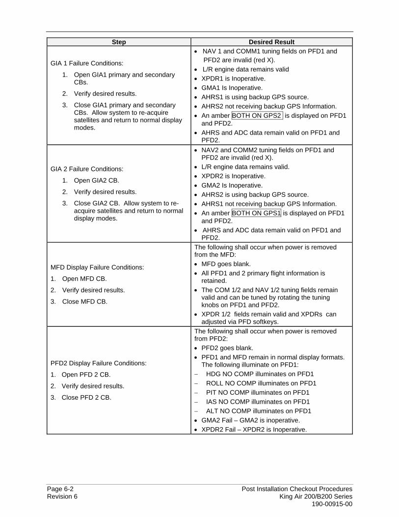
Page 6-2 Post Installation Checkout Procedures Revision 6 King Air 200/B200 Series 190-00915-00
Step Desired Result
GIA 1 Failure Conditions:
1. Open GIA1 primary and secondary CBs.
2. Verify desired results.
3. Close GIA1 primary and secondary CBs. Allow system to re-acquire satellites and return to normal display modes.
• NAV 1 and COMM1 tuning fields on PFD1 and PFD2 are invalid (red X). • L/R engine data remains valid • XPDR1 is Inoperative. • GMA1 Is Inoperative. • AHRS1 is using backup GPS source. • AHRS2 not receiving backup GPS Information. • An amber BOTH ON GPS2 is displayed on PFD1
and PFD2. • AHRS and ADC data remain valid on PFD1 and
PFD2.
GIA 2 Failure Conditions:
1. Open GIA2 CB.
2. Verify desired results.
3. Close GIA2 CB. Allow system to re-acquire satellites and return to normal display modes.
• NAV2 and COMM2 tuning fields on PFD1 and PFD2 are invalid (red X).
• L/R engine data remains valid. • XPDR2 is Inoperative. • GMA2 Is Inoperative. • AHRS2 is using backup GPS source. • AHRS1 not receiving backup GPS Information. • An amber BOTH ON GPS1 is displayed on PFD1
and PFD2. • AHRS and ADC data remain valid on PFD1 and
PFD2.
MFD Display Failure Conditions:
1. Open MFD CB.
2. Verify desired results.
3. Close MFD CB.
The following shall occur when power is removed from the MFD: • MFD goes blank. • All PFD1 and 2 primary flight information is
retained. • The COM 1/2 and NAV 1/2 tuning fields remain
valid and can be tuned by rotating the tuning knobs on PFD1 and PFD2.
• XPDR 1/2 fields remain valid and XPDRs can adjusted via PFD softkeys.
PFD2 Display Failure Conditions:
1. Open PFD 2 CB.
2. Verify desired results.
3. Close PFD 2 CB.
The following shall occur when power is removed from PFD2: • PFD2 goes blank. • PFD1 and MFD remain in normal display formats.
The following illuminate on PFD1: − HDG NO COMP illuminates on PFD1 − ROLL NO COMP illuminates on PFD1 − PIT NO COMP illuminates on PFD1 − IAS NO COMP illuminates on PFD1 − ALT NO COMP illuminates on PFD1 • GMA2 Fail – GMA2 is inoperative. • XPDR2 Fail – XPDR2 is Inoperative.
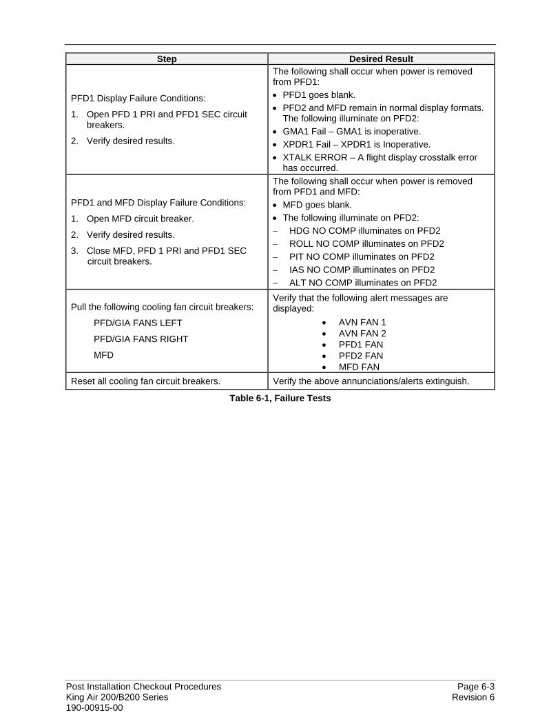
Post Installation Checkout Procedures Page 6-3 King Air 200/B200 Series Revision 6 190-00915-00
Step Desired Result
PFD1 Display Failure Conditions:
1. Open PFD 1 PRI and PFD1 SEC circuit breakers.
2. Verify desired results.
The following shall occur when power is removed from PFD1: • PFD1 goes blank. • PFD2 and MFD remain in normal display formats.
The following illuminate on PFD2: • GMA1 Fail – GMA1 is inoperative. • XPDR1 Fail – XPDR1 is Inoperative. • XTALK ERROR – A flight display crosstalk error
has occurred.
PFD1 and MFD Display Failure Conditions:
1. Open MFD circuit breaker.
2. Verify desired results.
3. Close MFD, PFD 1 PRI and PFD1 SEC circuit breakers.
The following shall occur when power is removed from PFD1 and MFD: • MFD goes blank. • The following illuminate on PFD2: − HDG NO COMP illuminates on PFD2 − ROLL NO COMP illuminates on PFD2 − PIT NO COMP illuminates on PFD2 − IAS NO COMP illuminates on PFD2 − ALT NO COMP illuminates on PFD2
Pull the following cooling fan circuit breakers:
PFD/GIA FANS LEFT
PFD/GIA FANS RIGHT
MFD
Verify that the following alert messages are displayed:
• AVN FAN 1 • AVN FAN 2 • PFD1 FAN • PFD2 FAN • MFD FAN
Reset all cooling fan circuit breakers. Verify the above annunciations/alerts extinguish.
Table 6-1, Failure Tests
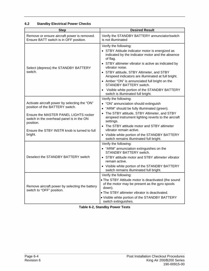
Page 6-4 Post Installation Checkout Procedures Revision 6 King Air 200/B200 Series 190-00915-00
6.2 Standby Electrical Power Checks
Step Desired Result Remove or ensure aircraft power is removed. Ensure BATT switch is in OFF position.
Verify the STANDBY BATTERY annunciator/switch is not illuminated
Select (depress) the STANDBY BATTERY switch.
Verify the following: • STBY Attitude indicator motor is energized as
indicated by the indicator motor and the absence of flag.
• STBY altimeter vibrator is active as indicated by vibrator noise.
• STBY attitude, STBY Altimeter, and STBY Airspeed indicators are illuminated at full bright.
• Amber “ON” is annunciated full bright on the STANDBY BATTERY switch.
• Visible white portion of the STANDBY BATTERY switch is illuminated full bright.
Activate aircraft power by selecting the “ON” position of the BATTERY switch. Ensure the MASTER PANEL LIGHTS rocker switch in the overhead panel is in the ON position. Ensure the STBY INSTR knob is turned to full bright.
Verify the following: • “ON” annunciation should extinguish • “ARM” should be fully illuminated (green). • The STBY attitude, STBY Altimeter, and STBY
airspeed instrument lighting reverts to the aircraft settings.
• The STBY attitude motor and STBY altimeter vibrator remain active.
• Visible white portion of the STANDBY BATTERY switch remains illuminated full bright.
Deselect the STANDBY BATTERY switch
Verify the following: • “ARM” annunciation extinguishes on the
STANDBY BATTERY switch. • STBY attitude motor and STBY altimeter vibrator
remain active. • Visible white portion of the STANDBY BATTERY
switch remains illuminated full bright.
Remove aircraft power by selecting the battery switch to “OFF” position.
Verify the following: • The STBY Attitude motor is deactivated (the sound
of the motor may be present as the gyro spools down).
• The STBY altimeter vibrator is deactivated. • Visible white portion of the STANDBY BATTERY
switch extinguishes. Table 6-2, Standby Power Tests
Post Installation Checkout Procedures Page 6-5 King Air 200/B200 Series Revision 6 190-00915-00
6.3 G1000 Backup Path Tests
Before performing these tests, remove power from the displays by pulling the following circuit breakers: • PFD1 primary • PFD1 secondary • PFD2 • MFD
1. Reboot PFD1, PFD2 and MFD while holding the ENT key on each display (far right key on MFD) until the words INITIALIZING SYSTEM appear.
2. In configuration mode, go to the GDU Page Group on PFD1.
3. On PFD1, activate the cursor and select PFD1 in the SELECT UNIT field and press ENT.
4. Observe the GRS77 and GDC74 DATA indicators in the ARINC 429 window.
5. Verify a green checkmark is present ( ), indicating the channels are receiving data.
6. On PFD1, activate the cursor and select PFD2 in the SELECT UNIT field and press the ENT key.
7. Repeat Steps 4 and 5.
8. On PFD1, activate the cursor and select MFD1 in the SELECT UNIT field and press the ENT key.
9. Repeat Steps 4 and 5.
10. On PFD1, go to the GIA Page Group. Go to the RS-232 / ARINC 429 CONFIG page.
11. Verify that GIA1 is selected in the SELECT UNIT field.
12. Observe the DATA indicators for all configured RS-232 and ARINC 429 channels (except GIA DEBUG), including the GRS 77 and GDC 74 ARINC 429 channels.
13. Verify all DATA indicators have a GREEN checkmark ( ) for those channels that are actively configured.
14. Activate the cursor and select GIA2 in the SELECT UNIT field, then press the ENT key.
15. Repeat steps 12 and 13.
16. On PFD1, go to the RS-485 CONFIGURATION page in the GIA Page Group.
17. Verify that GIA1 is selected in the SELECT UNIT field.
18. Observe the data indicators for all configured RS-485 channels.
19. Verify all DATA indicators have a GREEN checkmark ( ) for those channels that are actively configured.
20. Activate the cursor and select GIA2 in the SELECT UNIT field, then press the ENT key.
21. Repeat Steps 18 and 19.

Page 6-6 Post Installation Checkout Procedures Revision 6 King Air 200/B200 Series 190-00915-00
This page intentionally left blank
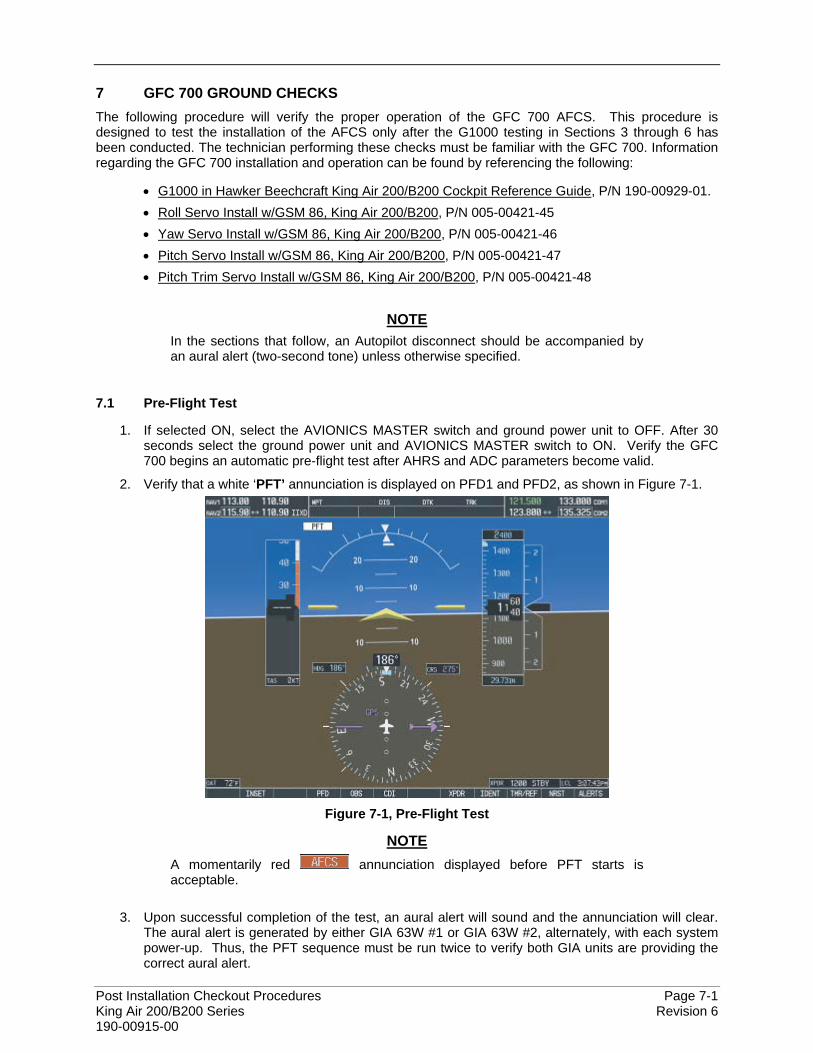
Post Installation Checkout Procedures Page 7-1 King Air 200/B200 Series Revision 6 190-00915-00
7 GFC 700 GROUND CHECKS The following procedure will verify the proper operation of the GFC 700 AFCS. This procedure is designed to test the installation of the AFCS only after the G1000 testing in Sections 3 through 6 has been conducted. The technician performing these checks must be familiar with the GFC 700. Information regarding the GFC 700 installation and operation can be found by referencing the following:
• G1000 in Hawker Beechcraft King Air 200/B200 Cockpit Reference Guide, P/N 190-00929-01. • Roll Servo Install w/GSM 86, King Air 200/B200, P/N 005-00421-45 • Yaw Servo Install w/GSM 86, King Air 200/B200, P/N 005-00421-46 • Pitch Servo Install w/GSM 86, King Air 200/B200, P/N 005-00421-47 • Pitch Trim Servo Install w/GSM 86, King Air 200/B200, P/N 005-00421-48
NOTE
In the sections that follow, an Autopilot disconnect should be accompanied by an aural alert (two-second tone) unless otherwise specified.
7.1 Pre-Flight Test
1. If selected ON, select the AVIONICS MASTER switch and ground power unit to OFF. After 30 seconds select the ground power unit and AVIONICS MASTER switch to ON. Verify the GFC 700 begins an automatic pre-flight test after AHRS and ADC parameters become valid.
2. Verify that a white ‘PFT’ annunciation is displayed on PFD1 and PFD2, as shown in Figure 7-1.
Figure 7-1, Pre-Flight Test
NOTE A momentarily red annunciation displayed before PFT starts is acceptable.
3. Upon successful completion of the test, an aural alert will sound and the annunciation will clear.
The aural alert is generated by either GIA 63W #1 or GIA 63W #2, alternately, with each system power-up. Thus, the PFT sequence must be run twice to verify both GIA units are providing the correct aural alert.
Page 7-2 Post Installation Checkout Procedures Revision 6 King Air 200/B200 Series 190-00915-00
NOTE If the ‘PFT’ annunciation turns red, the test has failed. Refer to the System Maintenance Manual for troubleshooting.
4. Repeat Steps 1 - 3 to test the PFT aural alert for the other GIA 63W.
5. Continue to Section 7.2.
7.2 AFCS Switch Checks
Verify that the AFCS system buttons and switches are operating correctly by performing the following:
1. Actuate both sections of the PITCH TRIM (NOSE UP/NOSE DN) switch to activate Manual Electric Pitch Trim (MEPT). Verify the trim clutch engages and the trim wheel drives in the requested direction. Check operation in both the up and down direction.
2. Press the AP/YD DISC TRIM INTRPT switch and hold while actuating the manual electric trim switch. Verify trim does not run and the trim wheel rotates freely when moved manually. Release the AP/YD DISC TRIM INTRPT button and PITCH TRIM switch.
3. Engage the autopilot by pressing the AP key on AFCS mode controller. Press and hold the left section of the manual electric trim switch. Verify the Autopilot disengages normally with an aural alert and the trim wheel rotates freely when moved manually.
4. Engage the autopilot again by pressing the AP key on the AFCS mode controller. Verify the pitch and roll clutches engage and resist movement of the control wheel. Press and hold the CWS switch and verify the control wheel moves freely when moved manually. Verify the green ‘AP’ at the top of PFD1 and PFD2 is replaced by a white ‘CWS’.
5. Release the CWS switch and press the ‘XFR’ key on the AFCS mode controller. Verify the clutches are engaged and resist movement of the control wheel. Press and hold the CWS switch and verify the control wheel moves freely when moved manually. Verify the green ‘AP’ at the top of PFD1 and PFD2 is replaced by a white ‘CWS’.
6. Release the CWS switch and press the AP/YD DISC TRIM INTRPT switch on the pilots control wheel. Verify the autopilot disengages with a flashing amber ‘AP’ annunciation on PFD1 and PFD2, accompanied by an aural alert. Verify that the control wheel is free in pitch and roll axes.
7. Engage the autopilot again by pressing the ‘AP’ key on the AFCS mode controller. Open AFCS SERVOS circuit breaker. Verify the autopilot disconnects and the abnormal disconnect is provided, consisting of a continuous aural alert and a flashing red/white ‘AP’ annunciation. Verify no AFCS annunciations (e.g. AFCS, PFT, Mistrim) remain on PFD1 or PFD2. Press the AP/YD DISC TRIM INTRPT switch to cancel the abnormal alert. Close the AFCS SERVOS circuit breaker to restore power to the system and wait for completion of the pre-flight test sequence.
8. Engage the autopilot again by pressing the ‘AP’ key on the AFCS mode controller. Ensure the autopilot is coupled to GIA1 by verifying the arrowhead next to the ‘XFR’ key on the AFCS mode controller is pointing to the pilot’s side. If the arrowhead points to the copilot’s side, press the ‘XFR’ key. Open GIA1 primary and secondary circuit breakers. Verify the autopilot disconnects with a continuous aural alert and a flashing red/white ‘AP’ annunciation. Press the AP/YD DISC TRIM INTRPT switch to cancel the alert and annunciation. Close the GIA1 primary and secondary circuit breakers and wait for completion of the pre-flight test sequence.
9. Press the ‘XFR’ key on the AFCS mode controller and engage the autopilot by pressing the ‘AP’ key on the AFCS Mode Controller. Press the AP/YD DISC TRIM INTRPT switch on the pilot side to disconnect the autopilot; verify the flashing amber ‘AP’ alert is displayed on PFD1 & 2.
10. Press the GO AROUND button on the left throttle. Verify ‘TO’ is annunciated on PFD1 and PFD2 for both PITCH and ROLL modes and the command bars should be at 8 degrees nose up and wings-level.
11. Press the Flight Director (FD) key on the AFCS mode controller to deactivate the GA mode. Press the AP key to engage the autopilot. Press the CWS button for a minimum of 5 seconds and release; verifying there is no residual force on the control stick for the pitch axis.

Post Installation Checkout Procedures Page 7-3 King Air 200/B200 Series Revision 6 190-00915-00
12. Disengage the autopilot by pressing the AP/YD DISC TRIM INTRPT switch on the co-pilot’s control wheel. Engage VS mode by pressing the VS key on the AFCS mode controller. Verify PFD1 and PFD2 display ‘VS’ in green and indicates a pitch reference of ‘0 FPM’.
13. Rotate the ALT SEL knob on the AFCS mode controller to enter a preselect altitude of 100 feet. 14. Press the FLC key on the AFCS mode controller and verify that ‘FLC’ is annunciated on PFD1
and PFD2 in green with a reference of 100 KTS. 15. Press the ALT key on the AFCS mode controller and verify that the ‘ALT’ annunciation is
displayed in green on PFD1 and PFD2 with an altitude reference equal to the aircraft altitude (within the nearest 20 feet).
16. Press the FD key and verify that the mode annunciations and command bars are removed from the display.
7.3 Autopilot Clutch Overpower Check
NOTE The GFC 700 uses electronic torque limiting as well as mechanical slip clutches to limit the maximum servo effort. When the system is on the ground, the electronic torque limiting is removed, allowing manual checks of the slip-clutch settings.
1. Engage the Autopilot by pressing the AP key on the AFCS mode controller.
2. Manually overpower the autopilot clutches in pitch, roll and yaw. If the Autopilot clutches cannot be overpowered, check the GSM 86 clutch cartridges. Refer to the servo installation drawing as applicable.
3. Actuate and hold PITCH TRIM switch in either the NOSE UP or NOSE DOWN direction to disconnect the autopilot. While the trim is running, restrain the aircraft pitch trim wheel and verify that the trim clutch can be overpowered. If it cannot be overpowered, check the GSM 86 clutch cartridge. Refer to the pitch trim servo installation drawing.
4. Engage the autopilot by pressing the AP key on the AFCS mode controller. Actuate and hold the manual electric trim switch in either the up or down direction to disconnect the autopilot. Verify that the trim wheel moves smoothly in both directions throughout the entire trim range during manual electric trim operation. If the trim wheel hesitates, this may indicate that the pitch trim clutch is slipping and proper clutch cartridge and cable tension should be verified. Refer to the System Maintenance Manual. If both clutch cartridge and cable tension are within tolerance, check the aircraft pitch trim system for excessive friction. Refer to the appropriate Hawker Beechcraft 200/B200 Series Maintenance Manual.
7.4 Manual Electric Pitch Trim Speed Check
1. Run MANUAL ELECTRIC PITCH TRIM in one direction until it runs against the mechanical stop.
2. Run the trim in the opposite direction, and using a stop watch or equivalent device, time the trim speed to the opposite mechanical stop. Verify the elapsed time for full travel measures 13 ± 3 seconds.
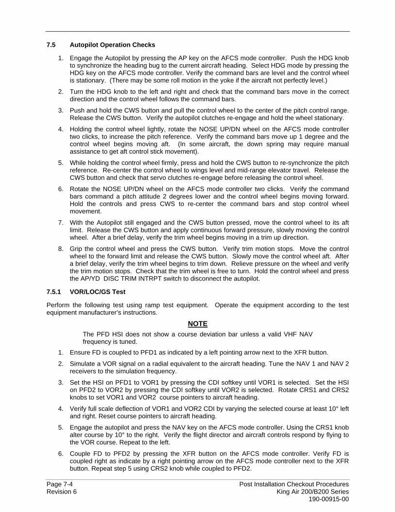
Page 7-4 Post Installation Checkout Procedures Revision 6 King Air 200/B200 Series 190-00915-00
7.5 Autopilot Operation Checks
1. Engage the Autopilot by pressing the AP key on the AFCS mode controller. Push the HDG knob to synchronize the heading bug to the current aircraft heading. Select HDG mode by pressing the HDG key on the AFCS mode controller. Verify the command bars are level and the control wheel is stationary. (There may be some roll motion in the yoke if the aircraft not perfectly level.)
2. Turn the HDG knob to the left and right and check that the command bars move in the correct direction and the control wheel follows the command bars.
3. Push and hold the CWS button and pull the control wheel to the center of the pitch control range. Release the CWS button. Verify the autopilot clutches re-engage and hold the wheel stationary.
4. Holding the control wheel lightly, rotate the NOSE UP/DN wheel on the AFCS mode controller two clicks, to increase the pitch reference. Verify the command bars move up 1 degree and the control wheel begins moving aft. (In some aircraft, the down spring may require manual assistance to get aft control stick movement).
5. While holding the control wheel firmly, press and hold the CWS button to re-synchronize the pitch reference. Re-center the control wheel to wings level and mid-range elevator travel. Release the CWS button and check that servo clutches re-engage before releasing the control wheel.
6. Rotate the NOSE UP/DN wheel on the AFCS mode controller two clicks. Verify the command bars command a pitch attitude 2 degrees lower and the control wheel begins moving forward. Hold the controls and press CWS to re-center the command bars and stop control wheel movement.
7. With the Autopilot still engaged and the CWS button pressed, move the control wheel to its aft limit. Release the CWS button and apply continuous forward pressure, slowly moving the control wheel. After a brief delay, verify the trim wheel begins moving in a trim up direction.
8. Grip the control wheel and press the CWS button. Verify trim motion stops. Move the control wheel to the forward limit and release the CWS button. Slowly move the control wheel aft. After a brief delay, verify the trim wheel begins to trim down. Relieve pressure on the wheel and verify the trim motion stops. Check that the trim wheel is free to turn. Hold the control wheel and press the AP/YD DISC TRIM INTRPT switch to disconnect the autopilot.
7.5.1 VOR/LOC/GS Test
Perform the following test using ramp test equipment. Operate the equipment according to the test equipment manufacturer’s instructions.
NOTE The PFD HSI does not show a course deviation bar unless a valid VHF NAV frequency is tuned.
1. Ensure FD is coupled to PFD1 as indicated by a left pointing arrow next to the XFR button.
2. Simulate a VOR signal on a radial equivalent to the aircraft heading. Tune the NAV 1 and NAV 2 receivers to the simulation frequency.
3. Set the HSI on PFD1 to VOR1 by pressing the CDI softkey until VOR1 is selected. Set the HSI on PFD2 to VOR2 by pressing the CDI softkey until VOR2 is selected. Rotate CRS1 and CRS2 knobs to set VOR1 and VOR2 course pointers to aircraft heading.
4. Verify full scale deflection of VOR1 and VOR2 CDI by varying the selected course at least 10° left and right. Reset course pointers to aircraft heading.
5. Engage the autopilot and press the NAV key on the AFCS mode controller. Using the CRS1 knob alter course by 10° to the right. Verify the flight director and aircraft controls respond by flying to the VOR course. Repeat to the left.
6. Couple FD to PFD2 by pressing the XFR button on the AFCS mode controller. Verify FD is coupled right as indicate by a right pointing arrow on the AFCS mode controller next to the XFR button. Repeat step 5 using CRS2 knob while coupled to PFD2.

Post Installation Checkout Procedures Page 7-5 King Air 200/B200 Series Revision 6 190-00915-00
7. Set CRS1 and CRS2 course pointers to aircraft heading.
8. Simulate a Localizer/Glideslope signal. Tune this signal on NAV 1 and NAV 2 receiver. Set the PFD1 HSI to LOC1 and PFD2 HSI to LOC2 by pressing CDI softkey until LOC1 and LOC2 is selected. Use the test equipment to center the deviation bars (localizer and glideslope) on PFD1 and PFD2.
9. Press the APR key on the AFCS mode controller. Verify that the LOC and GS annunciations are green on PFD1 and PFD2. Apply right/left and up/down localizer/glideslope signals using the test equipment. Verify that the Flight Director and flight controls respond appropriately.
10. Couple FD to PFD1 by pressing the XFR button on the AFCS mode controller. Verify FD is coupled to PFD1 as indicate by a left pointing arrow on the AFCS mode controller next to the XFR button.
11. Repeat step 10 using while coupled to PFD2.

Page 7-6 Post Installation Checkout Procedures Revision 6 King Air 200/B200 Series 190-00915-00
This page intentionally left blank
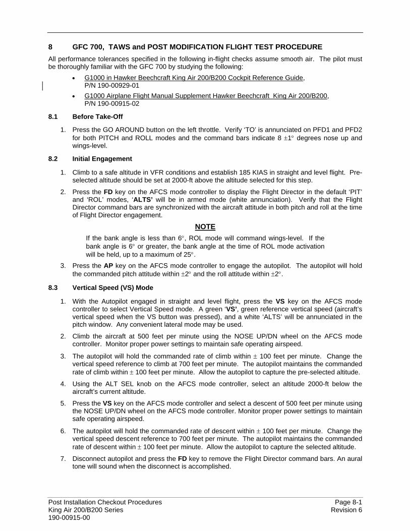
Post Installation Checkout Procedures Page 8-1 King Air 200/B200 Series Revision 6 190-00915-00
8 GFC 700, TAWS and POST MODIFICATION FLIGHT TEST PROCEDURE All performance tolerances specified in the following in-flight checks assume smooth air. The pilot must be thoroughly familiar with the GFC 700 by studying the following:
• G1000 in Hawker Beechcraft King Air 200/B200 Cockpit Reference Guide, P/N 190-00929-01
• G1000 Airplane Flight Manual Supplement Hawker Beechcraft King Air 200/B200, P/N 190-00915-02
8.1 Before Take-Off
1. Press the GO AROUND button on the left throttle. Verify ‘TO’ is annunciated on PFD1 and PFD2 for both PITCH and ROLL modes and the command bars indicate 8 ±1° degrees nose up and wings-level.
8.2 Initial Engagement
1. Climb to a safe altitude in VFR conditions and establish 185 KIAS in straight and level flight. Pre-selected altitude should be set at 2000-ft above the altitude selected for this step.
2. Press the FD key on the AFCS mode controller to display the Flight Director in the default ‘PIT’ and ‘ROL’ modes, ‘ALTS’ will be in armed mode (white annunciation). Verify that the Flight Director command bars are synchronized with the aircraft attitude in both pitch and roll at the time of Flight Director engagement.
NOTE If the bank angle is less than 6°, ROL mode will command wings-level. If the bank angle is 6° or greater, the bank angle at the time of ROL mode activation will be held, up to a maximum of 25°.
3. Press the AP key on the AFCS mode controller to engage the autopilot. The autopilot will hold the commanded pitch attitude within ±2° and the roll attitude within ±2°.
8.3 Vertical Speed (VS) Mode
1. With the Autopilot engaged in straight and level flight, press the VS key on the AFCS mode controller to select Vertical Speed mode. A green ‘VS’, green reference vertical speed (aircraft’s vertical speed when the VS button was pressed), and a white ‘ALTS’ will be annunciated in the pitch window. Any convenient lateral mode may be used.
2. Climb the aircraft at 500 feet per minute using the NOSE UP/DN wheel on the AFCS mode controller. Monitor proper power settings to maintain safe operating airspeed.
3. The autopilot will hold the commanded rate of climb within ± 100 feet per minute. Change the vertical speed reference to climb at 700 feet per minute. The autopilot maintains the commanded rate of climb within ± 100 feet per minute. Allow the autopilot to capture the pre-selected altitude.
4. Using the ALT SEL knob on the AFCS mode controller, select an altitude 2000-ft below the aircraft’s current altitude.
5. Press the VS key on the AFCS mode controller and select a descent of 500 feet per minute using the NOSE UP/DN wheel on the AFCS mode controller. Monitor proper power settings to maintain safe operating airspeed.
6. The autopilot will hold the commanded rate of descent within ± 100 feet per minute. Change the vertical speed descent reference to 700 feet per minute. The autopilot maintains the commanded rate of descent within ± 100 feet per minute. Allow the autopilot to capture the selected altitude.
7. Disconnect autopilot and press the FD key to remove the Flight Director command bars. An aural tone will sound when the disconnect is accomplished.
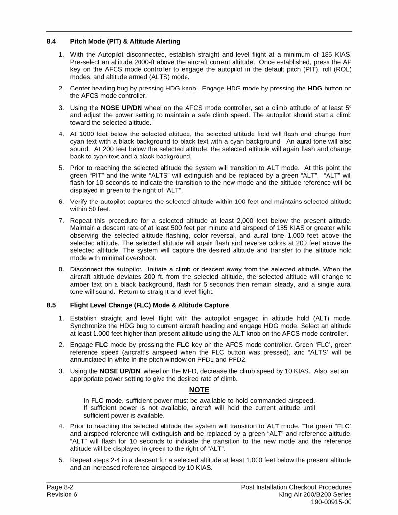
Page 8-2 Post Installation Checkout Procedures Revision 6 King Air 200/B200 Series 190-00915-00
8.4 Pitch Mode (PIT) & Altitude Alerting
1. With the Autopilot disconnected, establish straight and level flight at a minimum of 185 KIAS. Pre-select an altitude 2000-ft above the aircraft current altitude. Once established, press the AP key on the AFCS mode controller to engage the autopilot in the default pitch (PIT), roll (ROL) modes, and altitude armed (ALTS) mode.
2. Center heading bug by pressing HDG knob. Engage HDG mode by pressing the HDG button on the AFCS mode controller.
3. Using the NOSE UP/DN wheel on the AFCS mode controller, set a climb attitude of at least 5° and adjust the power setting to maintain a safe climb speed. The autopilot should start a climb toward the selected altitude.
4. At 1000 feet below the selected altitude, the selected altitude field will flash and change from cyan text with a black background to black text with a cyan background. An aural tone will also sound. At 200 feet below the selected altitude, the selected altitude will again flash and change back to cyan text and a black background.
5. Prior to reaching the selected altitude the system will transition to ALT mode. At this point the green “PIT” and the white “ALTS” will extinguish and be replaced by a green “ALT”. “ALT” will flash for 10 seconds to indicate the transition to the new mode and the altitude reference will be displayed in green to the right of “ALT”.
6. Verify the autopilot captures the selected altitude within 100 feet and maintains selected altitude within 50 feet.
7. Repeat this procedure for a selected altitude at least 2,000 feet below the present altitude. Maintain a descent rate of at least 500 feet per minute and airspeed of 185 KIAS or greater while observing the selected altitude flashing, color reversal, and aural tone 1,000 feet above the selected altitude. The selected altitude will again flash and reverse colors at 200 feet above the selected altitude. The system will capture the desired altitude and transfer to the altitude hold mode with minimal overshoot.
8. Disconnect the autopilot. Initiate a climb or descent away from the selected altitude. When the aircraft altitude deviates 200 ft. from the selected altitude, the selected altitude will change to amber text on a black background, flash for 5 seconds then remain steady, and a single aural tone will sound. Return to straight and level flight.
8.5 Flight Level Change (FLC) Mode & Altitude Capture
1. Establish straight and level flight with the autopilot engaged in altitude hold (ALT) mode. Synchronize the HDG bug to current aircraft heading and engage HDG mode. Select an altitude at least 1,000 feet higher than present altitude using the ALT knob on the AFCS mode controller.
2. Engage FLC mode by pressing the FLC key on the AFCS mode controller. Green ‘FLC’, green reference speed (aircraft’s airspeed when the FLC button was pressed), and “ALTS” will be annunciated in white in the pitch window on PFD1 and PFD2.
3. Using the NOSE UP/DN wheel on the MFD, decrease the climb speed by 10 KIAS. Also, set an appropriate power setting to give the desired rate of climb.
NOTE In FLC mode, sufficient power must be available to hold commanded airspeed. If sufficient power is not available, aircraft will hold the current altitude until sufficient power is available.
4. Prior to reaching the selected altitude the system will transition to ALT mode. The green “FLC” and airspeed reference will extinguish and be replaced by a green “ALT” and reference altitude. “ALT” will flash for 10 seconds to indicate the transition to the new mode and the reference altitude will be displayed in green to the right of “ALT”.
5. Repeat steps 2-4 in a descent for a selected altitude at least 1,000 feet below the present altitude and an increased reference airspeed by 10 KIAS.
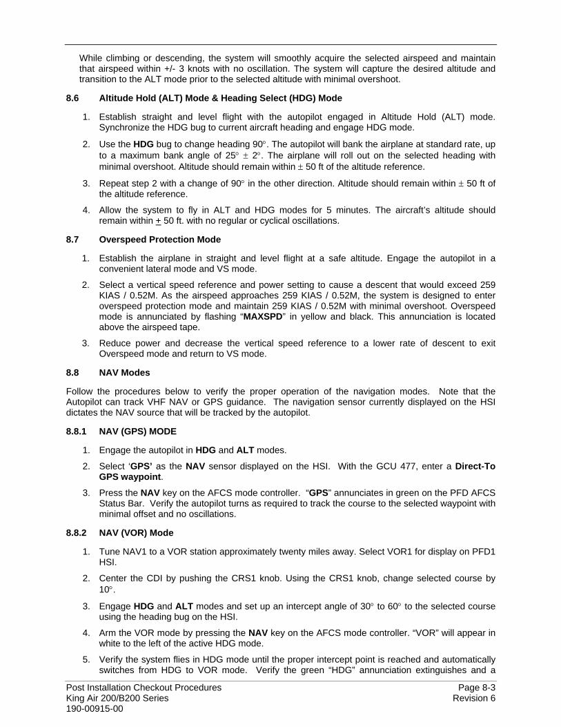
Post Installation Checkout Procedures Page 8-3 King Air 200/B200 Series Revision 6 190-00915-00
While climbing or descending, the system will smoothly acquire the selected airspeed and maintain that airspeed within +/- 3 knots with no oscillation. The system will capture the desired altitude and transition to the ALT mode prior to the selected altitude with minimal overshoot.
8.6 Altitude Hold (ALT) Mode & Heading Select (HDG) Mode
1. Establish straight and level flight with the autopilot engaged in Altitude Hold (ALT) mode. Synchronize the HDG bug to current aircraft heading and engage HDG mode.
2. Use the HDG bug to change heading 90°. The autopilot will bank the airplane at standard rate, up to a maximum bank angle of 25° ± 2°. The airplane will roll out on the selected heading with minimal overshoot. Altitude should remain within ± 50 ft of the altitude reference.
3. Repeat step 2 with a change of 90° in the other direction. Altitude should remain within ± 50 ft of the altitude reference.
4. Allow the system to fly in ALT and HDG modes for 5 minutes. The aircraft’s altitude should remain within + 50 ft. with no regular or cyclical oscillations.
8.7 Overspeed Protection Mode
1. Establish the airplane in straight and level flight at a safe altitude. Engage the autopilot in a convenient lateral mode and VS mode.
2. Select a vertical speed reference and power setting to cause a descent that would exceed 259 KIAS / 0.52M. As the airspeed approaches 259 KIAS / 0.52M, the system is designed to enter overspeed protection mode and maintain 259 KIAS / 0.52M with minimal overshoot. Overspeed mode is annunciated by flashing “MAXSPD” in yellow and black. This annunciation is located above the airspeed tape.
3. Reduce power and decrease the vertical speed reference to a lower rate of descent to exit Overspeed mode and return to VS mode.
8.8 NAV Modes
Follow the procedures below to verify the proper operation of the navigation modes. Note that the Autopilot can track VHF NAV or GPS guidance. The navigation sensor currently displayed on the HSI dictates the NAV source that will be tracked by the autopilot.
8.8.1 NAV (GPS) MODE
1. Engage the autopilot in HDG and ALT modes.
2. Select ‘GPS’ as the NAV sensor displayed on the HSI. With the GCU 477, enter a Direct-To GPS waypoint.
3. Press the NAV key on the AFCS mode controller. “GPS” annunciates in green on the PFD AFCS Status Bar. Verify the autopilot turns as required to track the course to the selected waypoint with minimal offset and no oscillations.
8.8.2 NAV (VOR) Mode
1. Tune NAV1 to a VOR station approximately twenty miles away. Select VOR1 for display on PFD1 HSI.
2. Center the CDI by pushing the CRS1 knob. Using the CRS1 knob, change selected course by 10°.
3. Engage HDG and ALT modes and set up an intercept angle of 30° to 60° to the selected course using the heading bug on the HSI.
4. Arm the VOR mode by pressing the NAV key on the AFCS mode controller. “VOR” will appear in white to the left of the active HDG mode.
5. Verify the system flies in HDG mode until the proper intercept point is reached and automatically switches from HDG to VOR mode. Verify the green “HDG” annunciation extinguishes and a
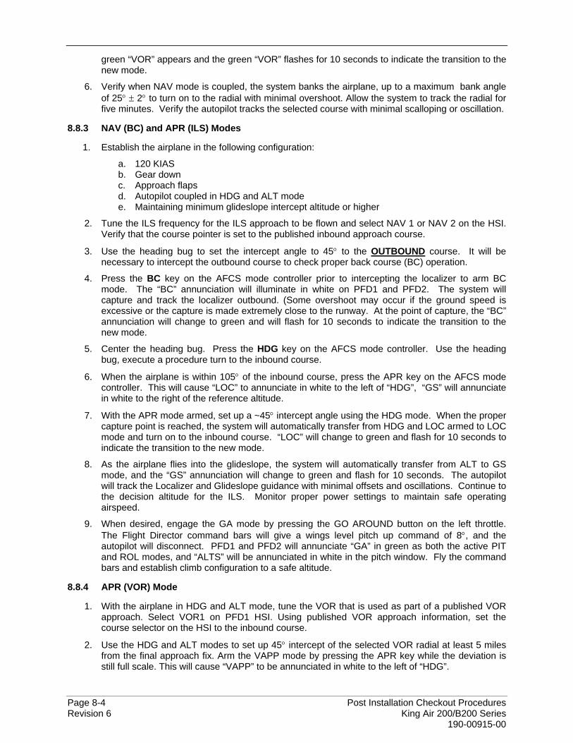
Page 8-4 Post Installation Checkout Procedures Revision 6 King Air 200/B200 Series 190-00915-00
green “VOR” appears and the green “VOR” flashes for 10 seconds to indicate the transition to the new mode.
6. Verify when NAV mode is coupled, the system banks the airplane, up to a maximum bank angle of 25° ± 2° to turn on to the radial with minimal overshoot. Allow the system to track the radial for five minutes. Verify the autopilot tracks the selected course with minimal scalloping or oscillation.
8.8.3 NAV (BC) and APR (ILS) Modes
1. Establish the airplane in the following configuration:
a. 120 KIAS b. Gear down c. Approach flaps d. Autopilot coupled in HDG and ALT mode e. Maintaining minimum glideslope intercept altitude or higher
2. Tune the ILS frequency for the ILS approach to be flown and select NAV 1 or NAV 2 on the HSI. Verify that the course pointer is set to the published inbound approach course.
3. Use the heading bug to set the intercept angle to 45° to the OUTBOUND course. It will be necessary to intercept the outbound course to check proper back course (BC) operation.
4. Press the BC key on the AFCS mode controller prior to intercepting the localizer to arm BC mode. The “BC” annunciation will illuminate in white on PFD1 and PFD2. The system will capture and track the localizer outbound. (Some overshoot may occur if the ground speed is excessive or the capture is made extremely close to the runway. At the point of capture, the “BC” annunciation will change to green and will flash for 10 seconds to indicate the transition to the new mode.
5. Center the heading bug. Press the HDG key on the AFCS mode controller. Use the heading bug, execute a procedure turn to the inbound course.
6. When the airplane is within 105° of the inbound course, press the APR key on the AFCS mode controller. This will cause “LOC” to annunciate in white to the left of “HDG”, “GS” will annunciate in white to the right of the reference altitude.
7. With the APR mode armed, set up a ~45° intercept angle using the HDG mode. When the proper capture point is reached, the system will automatically transfer from HDG and LOC armed to LOC mode and turn on to the inbound course. “LOC” will change to green and flash for 10 seconds to indicate the transition to the new mode.
8. As the airplane flies into the glideslope, the system will automatically transfer from ALT to GS mode, and the “GS” annunciation will change to green and flash for 10 seconds. The autopilot will track the Localizer and Glideslope guidance with minimal offsets and oscillations. Continue to the decision altitude for the ILS. Monitor proper power settings to maintain safe operating airspeed.
9. When desired, engage the GA mode by pressing the GO AROUND button on the left throttle. The Flight Director command bars will give a wings level pitch up command of 8°, and the autopilot will disconnect. PFD1 and PFD2 will annunciate “GA” in green as both the active PIT and ROL modes, and “ALTS” will be annunciated in white in the pitch window. Fly the command bars and establish climb configuration to a safe altitude.
8.8.4 APR (VOR) Mode
1. With the airplane in HDG and ALT mode, tune the VOR that is used as part of a published VOR approach. Select VOR1 on PFD1 HSI. Using published VOR approach information, set the course selector on the HSI to the inbound course.
2. Use the HDG and ALT modes to set up 45° intercept of the selected VOR radial at least 5 miles from the final approach fix. Arm the VAPP mode by pressing the APR key while the deviation is still full scale. This will cause “VAPP” to be annunciated in white to the left of “HDG”.
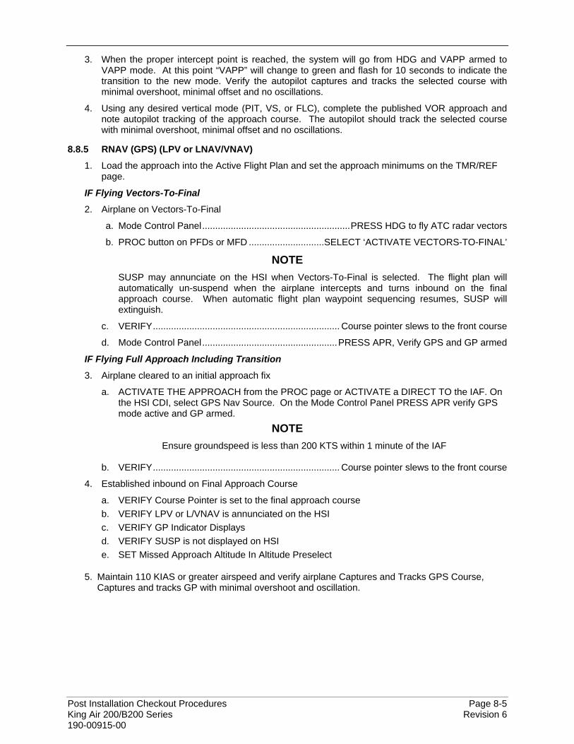
Post Installation Checkout Procedures Page 8-5 King Air 200/B200 Series Revision 6 190-00915-00
3. When the proper intercept point is reached, the system will go from HDG and VAPP armed to VAPP mode. At this point “VAPP” will change to green and flash for 10 seconds to indicate the transition to the new mode. Verify the autopilot captures and tracks the selected course with minimal overshoot, minimal offset and no oscillations.
4. Using any desired vertical mode (PIT, VS, or FLC), complete the published VOR approach and note autopilot tracking of the approach course. The autopilot should track the selected course with minimal overshoot, minimal offset and no oscillations.
8.8.5 RNAV (GPS) (LPV or LNAV/VNAV)
1. Load the approach into the Active Flight Plan and set the approach minimums on the TMR/REF page.
IF Flying Vectors-To-Final
2. Airplane on Vectors-To-Final
a. Mode Control Panel.........................................................PRESS HDG to fly ATC radar vectors
b. PROC button on PFDs or MFD .............................SELECT ‘ACTIVATE VECTORS-TO-FINAL’
NOTE SUSP may annunciate on the HSI when Vectors-To-Final is selected. The flight plan will automatically un-suspend when the airplane intercepts and turns inbound on the final approach course. When automatic flight plan waypoint sequencing resumes, SUSP will extinguish.
c. VERIFY........................................................................ Course pointer slews to the front course
d. Mode Control Panel....................................................PRESS APR, Verify GPS and GP armed
IF Flying Full Approach Including Transition
3. Airplane cleared to an initial approach fix
a. ACTIVATE THE APPROACH from the PROC page or ACTIVATE a DIRECT TO the IAF. On the HSI CDI, select GPS Nav Source. On the Mode Control Panel PRESS APR verify GPS mode active and GP armed.
NOTE Ensure groundspeed is less than 200 KTS within 1 minute of the IAF
b. VERIFY........................................................................ Course pointer slews to the front course
4. Established inbound on Final Approach Course
a. VERIFY Course Pointer is set to the final approach course b. VERIFY LPV or L/VNAV is annunciated on the HSI c. VERIFY GP Indicator Displays d. VERIFY SUSP is not displayed on HSI e. SET Missed Approach Altitude In Altitude Preselect
5. Maintain 110 KIAS or greater airspeed and verify airplane Captures and Tracks GPS Course, Captures and tracks GP with minimal overshoot and oscillation.

Page 8-6 Post Installation Checkout Procedures Revision 6 King Air 200/B200 Series 190-00915-00
8.8.6 Yaw Damper
1. With AP and YD engaged in ROL and PIT attitude hold mode and wings level, overpower left rudder 5-10° and release.
2. Verify the YD returns the airplane to the original attitude with no continuous oscillations or offsets.
3. Overpower right rudder 5-10° and release.
4. Verify the YD returns the airplane to the original attitude with no continuous oscillations or offsets.
5. Disengage the AP and YD.
6. Perform a rudder doublet and engage the YD.
7. Verify the YD returns the airplane to the original attitude with no continuous oscillations or offsets
8.9 TAWS ‘FIVE HUNDRED’ Call-out
1. During approach, verify that the ‘FIVE HUNDRED’ voice call-out is issued at approximately 500’ AGL (GPS altitude).
2. For installations configured for TAWS-A voice call-outs, verify additional voice call-outs are issued at approximately 400’, 300’, 200’ and 100’ AGL (GPS altitude.)

Post Installation Checkout Procedures Page 9-1 King Air 200/B200 Series Revision 6 190-00915-00
9 SIGNATURES
Complete the information below. A copy of this procedure should be kept with the aircraft records. Testing Completed By (Print):
Signature:
Date: