g1000 system flightsim developers pilot handbook.pdf · g1000 system flightsim developers - 3 -...
TRANSCRIPT

G1000 System FlightSim Developers
- 1 -
EULA
All rights reserved per the terms of the End User License Agreement. No part of this manual
may be scanned, reproduced, copied, transmitted, distributed, downloaded or used for any purpose
without the express written consent of FSD International.
Information contained herein is subject to change without notice.
GPS Basics
The altitude calculated by the G1000 is geometric height above mean sea level and could vary
significantly from altitude displayed by pressure altimeters in aircraft. GPS accuracy may be
degraded by the U.S. Department of Defense-imposed Selective Availability (SA) programs.
GPS receivers operate by receiving and decoding very low power radio signals broadcast by
satellites. It is possible that in some situations other radio equipment or electronic equipment used
in close proximity to a GPS receiver may create electromagnetic interference (EM/) which may
affect the ability of the GPS receiver to receive and decode the satellite signals. In such event, the
interference may be reduced or eliminated by switching off the source of interference or moving
the GPS receiver away from it.
About This Manual
The Getting Started section describes and illustrates the General Operation of the unit in the form
of step by step instructions. The General Operation Section goes into more descriptive detail on the
basic features of the GPS, moving map, COM, NAV and Transponder radios.
Getting Started
This guide describes the operation of the G1000 system. The G1000 provides a new, higher level of
accuracy integrity, integration, flight planning capability, and convenience for the pilot.
The G1000 combines a large number of easily accessible controls to use the high-resolution color
multi-function display, NAV and COM transceivers, GPS/WMS navigator, and transponder controller
all in a single unit.
The Getting Started section of this Pilot's Guide covers the details, so you can get the most out of
your G1000 quickly. This section and the Quick Reference Guide, when used with the simulator for
practice, will prepare you to get the most out your equipment.

G1000 System FlightSim Developers
- 2 -
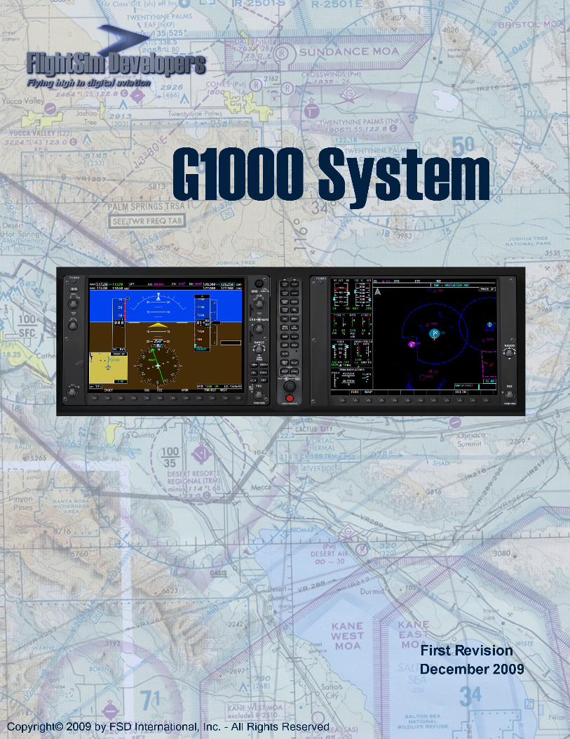
The G1000 System consists of two glass cockpit displays: the Primary Flight Display (PFD) and the
Multi Function Display (MFD. This display system is designed to increase your situational awareness
at all times, providing information on the aircraft's attitude, performance, and position. Each of
these displays will be described in more detail in the General Operation Section.
PFD MFD
Softkeys
Softkeys are keys that can be reconfigured via software to do different things in different
situations. One button can serve multiple purposes. Softkeys along the bottom of both the PFD and
MFD provide you with access to numerous functions and pages in the G1000. If there is text above
a softkey button, then it is an active softkey, and pressing the button will have an effect.
Other controls, for the radios, HSI, autopilot and display functions are controlled by
conventional rotary knobs. Many of these knobs have an outer ring and an inner
knob, each controlling different functions. For example, a radio knob’s outer ring
would control the decimal frequency values, while the inner knob will control the
whole numbers of the radio frequency.
In the case of radio knobs, pressing the inner knob via right mouse click will switch
control between frequency 1 and frequency 2.

G1000 System FlightSim Developers
- 3 -
General Operation
Power Control
The knob at the top left corner of each of the G1000 units controls power on/off. When you depress
the power button the system will go through a few different display screens while the system
initializes.
Note:
If you load your aircraft when the master power and master avionics switches are on the displays
will already be on and ready to operate.
THE PRIMARY FLIGHT DISPLAY
The Primary Flight Display (PFD) provides all the information displayed on a traditional airspeed
indicator, attitude indicator, altimeter, vertical speed indicator, horizontal situation indicator, and
turn coordinator in a modern, easy-to-scan format featuring a large horizon that's easy to see. The
PFD also displays communication and navigational radio information, flight plan data, an inset
moving map, outside air temperature, transponder status, and time of day.

G1000 System FlightSim Developers
- 4 -
NAV/COM Radio Operation
1. Frequency Window
2. Inner and outer control knobs
3. Frequency swap key
The NAV radios are on the upper left corner of the PFD. The COM radios are in the upper right
corner. The radio frequency window (1) displays active and standby frequencies for dual receivers
for both NAV and COM, as well as the identifier of a valid, identified navigation aid. The active
frequency of each radio is on the right and the standby frequency is on the left. The cyan-colored
tuning box indicates which standby frequency will be set using the NAV knob.
To swap the standby frequency and the active frequency, press the Frequency swap key (3):
To tune the standby frequencies for the NAV receivers, rotate the NAV Frequency Selector knobs
(2). The inner knob tunes whole MHz values and the outer ring tunes decimal values.
To toggle the cyan-colored indicator box, and control between
transceivers 1 and 2, push the inner knob in using a right mouse click.
Navigation Status Bar The Navigation Status Bar displays flight plan information when flying a
route created using the Flight Planner or the G1000 Direct-to function:
• Next waypoint
• Distance to the next waypoint (DIS)
• Desired track to the next waypoint (DTK)
• Current track (TRK)
• Navigation annunciations
G1000 System FlightSim Developers
- 5 -
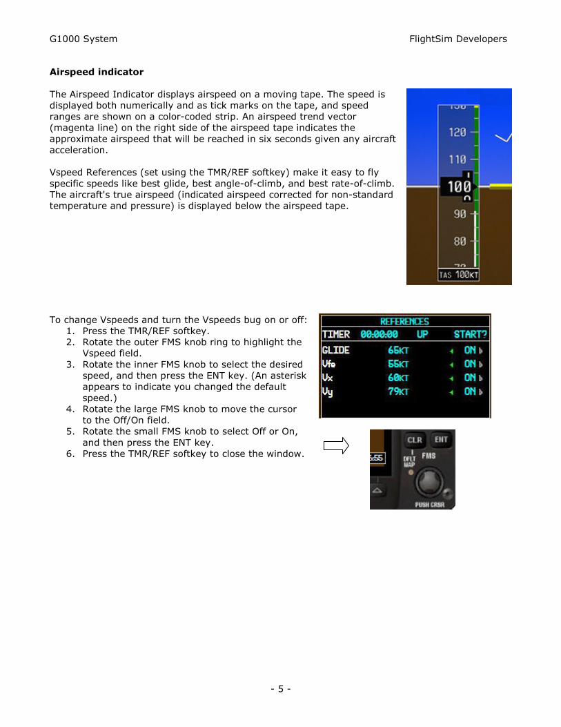
Airspeed indicator
The Airspeed Indicator displays airspeed on a moving tape. The speed is
displayed both numerically and as tick marks on the tape, and speed
ranges are shown on a color-coded strip. An airspeed trend vector
(magenta line) on the right side of the airspeed tape indicates the
approximate airspeed that will be reached in six seconds given any aircraft
acceleration.
Vspeed References (set using the TMR/REF softkey) make it easy to fly
specific speeds like best glide, best angle-of-climb, and best rate-of-climb.
The aircraft's true airspeed (indicated airspeed corrected for non-standard
temperature and pressure) is displayed below the airspeed tape.
To change Vspeeds and turn the Vspeeds bug on or off:
1. Press the TMR/REF softkey.
2. Rotate the outer FMS knob ring to highlight the
Vspeed field.
3. Rotate the inner FMS knob to select the desired
speed, and then press the ENT key. (An asterisk
appears to indicate you changed the default
speed.)
4. Rotate the large FMS knob to move the cursor
to the Off/On field.
5. Rotate the small FMS knob to select Off or On,
and then press the ENT key.
6. Press the TMR/REF softkey to close the window.

G1000 System FlightSim Developers
- 6 -
Attitude Indicator
The aircraft's attitude relative to the horizon is
displayed via the large blue sky, brown ground, and
white horizon line that extends the width of the PFD.
The Attitude Indicator indicates degrees of pitch and
degrees of roll.
The Slip/Skid Indicator is the small bar under the Roll
Pointer. It moves away from the Roll Pointer to
indicate slip or skid, just like the ball on a traditional
Turn Coordinator.
Altimeter
The Altimeter displays barometric altitude in feet on a moving tape. The altitude
is displayed both numerically and as tick marks on the tape. An altitude trend
vector (magenta line) on the left side of the altitude tape indicates the
approximate altitude that will be reached in six seconds given the current
vertical speed. A reference altitude can be set in the box above the altitude
tape, and a bug on the altitude tape indicates the reference altitude. The
selected barometric pressure is displayed below the altitude tape.
To set the Altitude Reference bug rotate the ALT
knob. The large knob sets thousands of feet and
small ALT knob sets hundreds of feet.
To set the altimeter barometric pressure, rotate the
outer ring of the CRS/BARO knob.
When an ILS is tuned in the active NAV radio, a
Vertical Deviation/Glideslope Indicator appears on the
left side of the altimeter. A green diamond indicates
vertical deviation (like a glideslope needle). Marker
beacon annunciations are displayed to the left of the
altitude reference box. Vertical Speed Indicator The
Vertical Speed Indicator is to the right of the altitude
tape. A pointer indicates the aircraft's vertical speed in
hundreds of feet.

G1000 System FlightSim Developers
- 7 -
Horizontal Situation Indicator
The Horizontal Situation Indicator (HSI) displays a rotating
compass card with the aircraft's current heading at the top.
A heading bug on the compass rose can be set to a desired
heading, and the selected heading appears in a box to the left of
the HSI.
To set the Heading bug, rotate the Heading
Selector knob or press the Heading Selector
knob to synchronize with the aircraft's current
heading.
Desired navigational course is indicated by a course pointer arrow
just like a traditional HSI, and the selected course appears to the
right of the HSI. The Course Deviation Indicator (CDI) moves to
the left or right of the course pointer to indicate the aircraft's
position relative to the course.
To set a course (NAV1 & NAV2 modes only), rotate the inner
CRS/BARO knob to the desired course.
To change navigation sources, press the CDI
softkey to toggle between GPS, NAV1, NAV2,
LOC1, and LOC2 (if a valid frequency is tuned).
Turn Rate Indicator
The Turn Rate Indicator is located above the rotating compass card on
the HSI. A magenta trend vector indicates the heading predicted in six
seconds given the current turn rate. Tick marks indicate standard and
half-standard rate turns.
G1000 System FlightSim Developers
- 8 -
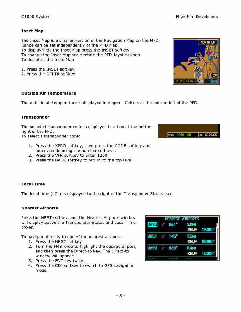
Inset Map
The Inset Map is a smaller version of the Navigation Map on the MFD.
Range can be set independently of the MFD Map.
To display/hide the Inset Map press the INSET softkey.
To change the Inset Map scale rotate the PFD Joystick knob.
To declutter the Inset Map
1. Press the INSET softkey
2. Press the DCLTR softkey
Outside Air Temperature
The outside air temperature is displayed in degrees Celsius at the bottom left of the PFD.
Transponder
The selected transponder code is displayed in a box at the bottom
right of the PFD.
To select a transponder code:
1. Press the XPDR softkey, then press the CODE softkey and
enter a code using the number softkeys.
2. Press the VFR softkey to enter 1200.
3. Press the BACK softkey to return to the top level.
Local Time
The local time (LCL) is displayed to the right of the Transponder Status box.
Nearest Airports
Press the NRST softkey, and the Nearest Airports window
will display above the Transponder Status and Local Time
boxes.
To navigate directly to one of the nearest airports:
1. Press the NRST softkey
2. Turn the FMS knob to highlight the desired airport,
and then press the Direct-to key. The Direct-to
window will appear.
3. Press the ENT key twice.
4. Press the CDI softkey to switch to GPS navigation
mode.

G1000 System FlightSim Developers
- 9 -
GPS System
The GPS/Navigation information that appears on the PFD is presented on pages, and you can only
view one page at a time. Some pages are organized into groups of related pages, called page
groups. Think of page groups as chapters in a book, and pages as the pages within each chapter.
There are three page groups modeled in the Flight Simulator G1000. The Map (MAP) page group
includes:
Navigation Map page
Waypoint page group includes:
H Airport Information page
H Intersection Information page
H NDB Information page
H VOR Information page
The Nearest page group includes:
H Nearest Airports page
H Nearest Intersections page
H Nearest NDB page
H Nearest VOR page
Navigating the Pages
To move through the pages of the MFD you'll use the FMS knobs.
To select a page group, rotate the outer FMS knob to select a page group
(MAP, WPT, or NRST).
To select a page within a page group, rotate the inner FMS knob.
The bottom right corner of each page provides a graphical indication of which page group and page
within that group is selected:
Additionally, the selected page group and page are displayed at the top of the MFD:
You'll also use the following keys as you work with the MFD pages:
Key Function
Clear - Press to erase information or cancel an entry. Press and
hold to return to the Navigation Map page at any time.
Enter - Press to accept a menu selection or data entry.
Menu - Press to display context-sensitive options.
Cursor - Press (small FMS knob) to access and enter data.

G1000 System FlightSim Developers
- 10 -
THE MULTI FUNCTION DISPLAY
The G1000's Multi Function Display (MFD) combines engine information with a full-featured GPS
and moving map display. To display the MFD, press SHIFT+3.
Engine Indication System (EIS) The G1000 Engine Indication System is displayed on the left side of
the MFD and includes gauges, bar graphs, and numeric readouts of engine parameters.
The EIS displays all critical engine, fuel, and electrical indications.