gas monitoring in rpc by means of non-invasive - iopscience
TRANSCRIPT

Journal of Instrumentation
Gas monitoring in RPC by means of non-invasiveplasma coated POF sensorsTo cite this article S Grassini et al 2012 JINST 7 P12006
View the article online for updates and enhancements
You may also likeGamma ray background radiation for glasselectrode RPCs in the CMSLHCenvironment estimation approach withGEANT4 Monte Carlo simulationpackagesJ T Rhee Christopher Chun M Jamil et al
-
The Resistive Plate Chambers of theATLAS experiment performance studiesGiordano Cattani and the RPC group
-
Effects of the vortex line shape on thecritical current density in high Tcsuperconducting film with nanorod pinningcentersY Jung K Kwak W Lee et al
-
Recent citationsAlessio Gullino et al-
Design and Deployment of Low-CostPlastic Optical Fiber Sensors for GasMonitoringSabrina Grassini et al
-
The critical influence of surfacetopography on nanoindentationmeasurements of a-SiCH filmsVladimir Cech et al
-
This content was downloaded from IP address 17511313528 on 18122021 at 1827
2012 JINST 7 P12006
PUBLISHED BY IOP PUBLISHING FOR SISSA MEDIALAB
RECEIVED July 30 2012ACCEPTED October 30 2012
PUBLISHED December 7 2012
SPECIAL ISSUE ON RESISTIVE PLATE CHAMBERS AND RELATED DETECTORS RPC2012
Gas monitoring in RPC by means of non-invasiveplasma coated POF sensors
S Grassinia1 M Ishtaiwib M Parvisb L Benussic S Biancoc S Colafranceschic
and D Piccoloc
aDipartimento di Scienza Applicata e Tecnologia Politecnico di TorinoCorso Duca degli Abruzzi 24 Torino Italy
bDipartimento di Elettronica e Telecomunicazioni Politecnico di TorinoCorso Duca degli Abruzzi 24 Torino Italy
cLaboratori Nazionali di Frascati dellrsquoINFNv E Fermi 40 Frascati 00044 Italy
E-mail sabrinagrassinipolitoit
ABSTRACT Resistive Plate Counters (RPC) are employed as muon detectors in many high-ratehigh-energy physics experiments such as the Compact Muon Solenoid (CMS) experiment cur-rently under way in the Large Hadron Collider (LHC) accelerator at the European Center for Nu-clear Research (CERN) A gas mixture containing C2H2F4 iminusC4H10 and SF6 is recirculated insidethe RPCs during their use and subjected to degradation due tothe production of fluoride ions whichlimits the sensitivity of the RPCs This paper describes a new sensor that is able to detect low con-centrations of fluoride ions in gas mixtures The sensor is made of a plastic optic fiber (POF) whichis made sensitive to Fminus gaseous ions by means of a thin layer of a glass-like material depositedvia plasma onto the fiber core The Fminus ions attack the glass-like film and alter the transmissioncapability of the fiber so that the detection simply requiresa LED and a photodiode The sensorexploits a cumulative response which makes it suitable for direct estimation of the total exposureto the Fminus ions thus providing a tool that can be used to tune the maintenance of the gas filters Theglass-like film is deposited by means of plasma enhanced chemical vapor deposition (PECVD) oforganosilicons monomers which allows the deposition to beperformed a low temperature in orderto avoid damaging the fiber core
KEYWORDS Gaseous detectors Gas systems and purification Resistive-plate chambers
1Corresponding author
ccopy 2012 IOP Publishing Ltd and Sissa Medialab srl doi1010881748-0221712P12006
2012 JINST 7 P12006
Contents
1 Introduction 1
2 Sensor design 2
3 Experimental results 531 Radiation effect 532 Fiber coating 533 Exposure to HF 7
4 Conclusions 9
1 Introduction
Resistive Plate Counter (RPC) [1] detectors are widely used in nuclear and particle physics forthe detection and timing of muon particles The adoption of an F-based gas mixture as an activemedium in RPCs makes it necessary to understand what damage it can have on RPC materials whatcontaminants are produced in the recirculation systems which are the effects effects connected totheir use in high-radiation areas The results of a study on optical sensors for fluorine contaminantsare reported hereafter The study to establish a possible application of such optical sensors in theRPC muon detector [2] of the Compact Muon Solenoid (CMS) experiment [3] in the Large HadronCollider (LHC) at the European Center for Nuclear Research (CERN) in Geneva (Switzerland)The RPCs which are employed in the CMS are composed of two bakelite plates kept 2 mm apartby means of spacers The plates are maintained at a voltage difference of about 9 kV in order toobtain an electric field of about 45 kVmm between the plates The space between the plates isfilled with an insulating gas whose ionization connected tothe passage of a charged particle isused for particle detection The gas is a mixture of 962 of C2H2F4 35 of iminusC4H10 and 03SF6 and is maintained at a fixed relative humidity of 45 A closed-loop recirculation system isused because of the large volume and cost of the gas being used During RPC operation the gasmixture may be polluted by contaminants that increase the RPC dark current One of the identifiedcontaminants which is critical for its reactivity and difficult to detect is hydrogen fluoride (HF)
The average HF production of one CMS RPC chamber has been estimated to be about25 micromolh which corresponds to concentrations in the absence of filters of some parts per mil-lion [4 5] For this reason 90 of the gas mixture is recirculated andpurified by 3 gas filters while10-20 of fresh gas is injected into the loop thus reducingthe HF concentration to 01 micromolh
The concentration of contaminants is monitored by means of electrochemical Fminus sensors andgas chromatography Gas sampling points are located beforeand after each filter The samplingpoints make it possible to perform chemical samplings in a lithium hydroxide solution whosecomposition is determined at fixed intervals by means of chemical analyses
ndash 1 ndash
2012 JINST 7 P12006
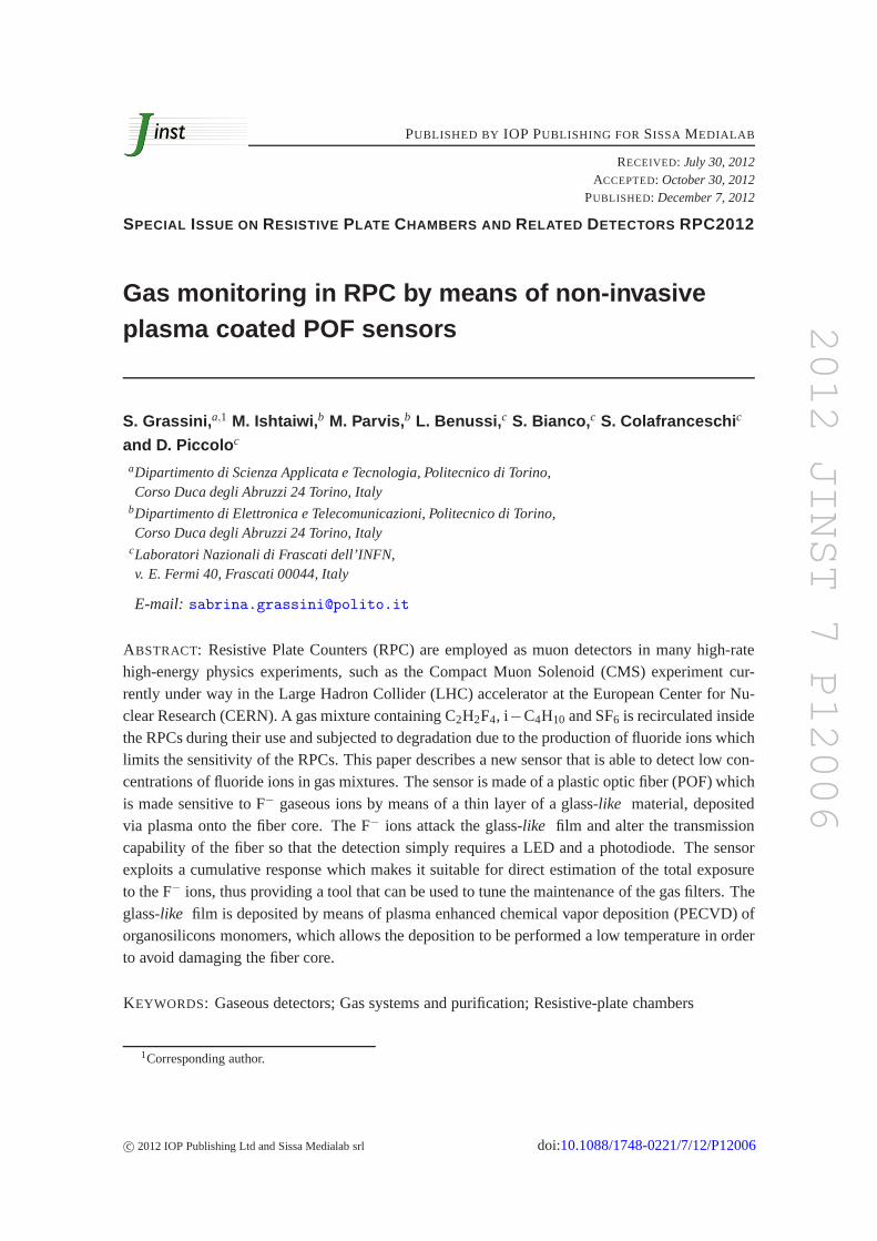
Figure 1 Sensor assembly with LED fiber and PD
Commercially available sensors for fluoride ion detection (eg galvanic-type sensors that arebased on MnO2 gas-diffusion electrodes [6]) have a measuring range of 10minus20 ppm which is toohigh for this kind of measurement These commercial Hydrogen Fluoride sensors (eg from CEAInstruments Inc GasDetectors USA) are designed for personal safety and have costs in excess of500$ per unit so that their massive use for a complete RPC monitoring is not feasible
More sensitive sensors such as tin dioxide and Al-doped graphene based devices [7ndash9] havebeen proposed to detect hydrogen fluoride traces at part-per-billion concentration but they all havea higher cost
Intrinsic sensors based on Plastic Optical Fibers (POFs) made of poly-methyl-methacrylate(PMMA) [10 11] could be an interesting alternative provided they can be made sensitive tofluoride ions The use of POFs for sensing applications is rapidly growing [12ndash14] because ofthe cost-effectiveness of the POFs and the easiness of use connected to their large diameters(025 mmminus1 mm) which permit simple and cheap plastic connectors to beused while still main-taining a good optical coupling [15] Fiber optics can be used to develop intrinsic sensors thanksto several different principles (fiber grating scintillation light attenuation changes due to pollutantabsorbtion in the core light losses due to fiber bending etc [16 17]) However POFs offer theadvantage of having a remarkable evanescent field which extends outside the core and which canbe used to develop sensors based on the propagation loss change that occurs due to the interactionof the evanescent field with the surrounding media
2 Sensor design
A fiber based sensor that exploits the interaction of the evanescent field with the surrounding envi-ronment can easily be arranged with a structure composed of alight emitting diode an optic fiberand a photodiode as shown in figure1
The fiber has a length of about 10 cm The used LED (Kingbright L-53SRD-G) emits in thevisible red region (wavelength 635 nmndash680 nm) and has been selected since PMMA has a stableattenuation value in the red region [22] when exposed to radiations A wide band photodiode(Osram SFH 213) is also employed
Both LED and PD cupolas are drilled with 1 mm holes the fiber isinserted into the holes andbonded to the components using liquid PMMA The fiber is then cured in an oven at 60C for threedays to ensure complete polymerization of the liquid PMMA Finally the assembly is bonded to aPVC support so that the fiber is retained in a fixed position
ndash 2 ndash
2012 JINST 7 P12006
In order to exploit the use of the evanescent field the POF cladding must be removed and thecore exposed so that the sensitive film can directly interactwith the evanescent field
Commercially available fibers commonly used for telecommunication purposes costing about1$ per meter can be employed to develop the sensor These fibers are step-index highlymulti-mode POFs with a 098 mm diameter PMMA core surrounded by a 001 mm fluoropoly-mer cladding
The cladding can be removed either by means of a mechanical process or by means of a chem-ical process The mechanical approach is difficult to carry out without damaging the core which iscomposed of PMMA that is a relatively soft material on the other hand a pure chemical approachis not feasible since the long exposure to the solvent that isnecessary to obtain the complete dis-solution of the fluoropolymer would damage the core For thisreasonthe authors have employeda mixed chemico-mechanical approach Initially the fiber is dipped into ethylacetate for 40 s sothat the fluoropolymer is attacked then the cladding is stripped using a soft paper towel which isable to remove the fluoropolymer without damaging the core
Once the cladding has been removed the sensitive film must bedeposited using a low temper-ature process since the PMMA core is damaged at temperaturehigher than 80C A good solutionwhich also allows a precise control of the layer structure tobe obtained is the use of low pressureplasma treatments or rsquocold plasmasrsquo Plasma Enhanced Chemical Vapor Deposition (PECVD) canbe used to develop very sensitive sensors [18] PECVD modifies the fiber surface properties eitherby grafting different functional groups or by depositing thin films whose physico-chemical andoptical properties can be changed over a broad range simply by making a proper selection of theexperimental parameters
The critical aspect in the design of a POF sensor that exploits the evanescent field and itsinteraction with the surrounding media in order to achieve sensitivity to the quantity of interestconcerns the selection of the sensitive film The film that hasto be deposited on the fiber coremust be capable of reacting with the sensed quantity of interest with a reaction which alters thecapability of the fiber of transmitting the light In addition to achieve the required selectivitythe film must have a minimal reacting capability with respectto other quantities present in thesurrounding environment which could also affect the lighttransmission
This selectivity can easily been obtained in the case of fluoride ions by employing a glass-like thin film Glass has a higher refractive index than the PMMA and thus affects light transmis-sion to a great extent It is attacked by the Fminus ions and is almost unaffected by other quantitiesTwo problems arise first the direct deposition of glass ontothe fiber is impossible since the melt-ing temperature of glass is much higher than the melting temperature of PMMA second a carefulcontrol of the glass thickness is fundamental to obtain goodinteraction with the evanescent fieldIt is important to note that the reaction between glass and fluoride ions is not reversible and leadsto the formation of silicon tetrafluoride (SiF4)
SiO2+4HFrArr SiF4 +2H2O (21)
The developed sensor shows intrinsic cumulative behaviorie the sensor output is propor-tional to the integral of the exposure to the HF vapors When coupled to conventional sensors forthe detection of other contaminants such as O2 N2 H2O the sensor will provide a direct measure-ment of the residual purifier lifetime The cumulative mode of operation requires that the sensorshould be discarded after use thus dictating the need for a cheap product
ndash 3 ndash
2012 JINST 7 P12006
The fiber can therefore be coated with an SiOx film which has a very similar composition andamorphous structure to glass SiOx thin films with thicknesses of up to a few hundred nanome-ters can easily be deposited on the POF surface by means of PECVD starting from organosili-con monomers
The plastic fibers were therefore treated in a plasma fed withtetraethoxysilane (TEOS) O2and Ar in different ratios The plasma discharge was performed at a pressure of 5 Pa and with aninput power of 50 W The thickness of the deposited SiOx film can be changed simply by varyingthe deposition time
The PECVD reactor employed in this study consists of a stainless steel vacuum chamber con-nected to a turbomolecular pump backed up by a rotary pump A 1kW 1356 MHz RF powergenerator connected through an impedance matching unit is used to ignite the discharge A throt-tle valve and a pressure gauge permit the chamber pressure tobe controlled Four injection linesequipped with mass flow controllers permit quaternary discharge gas mixtures to be used A sepa-rate controller is used for the injection of the film precursor vapor
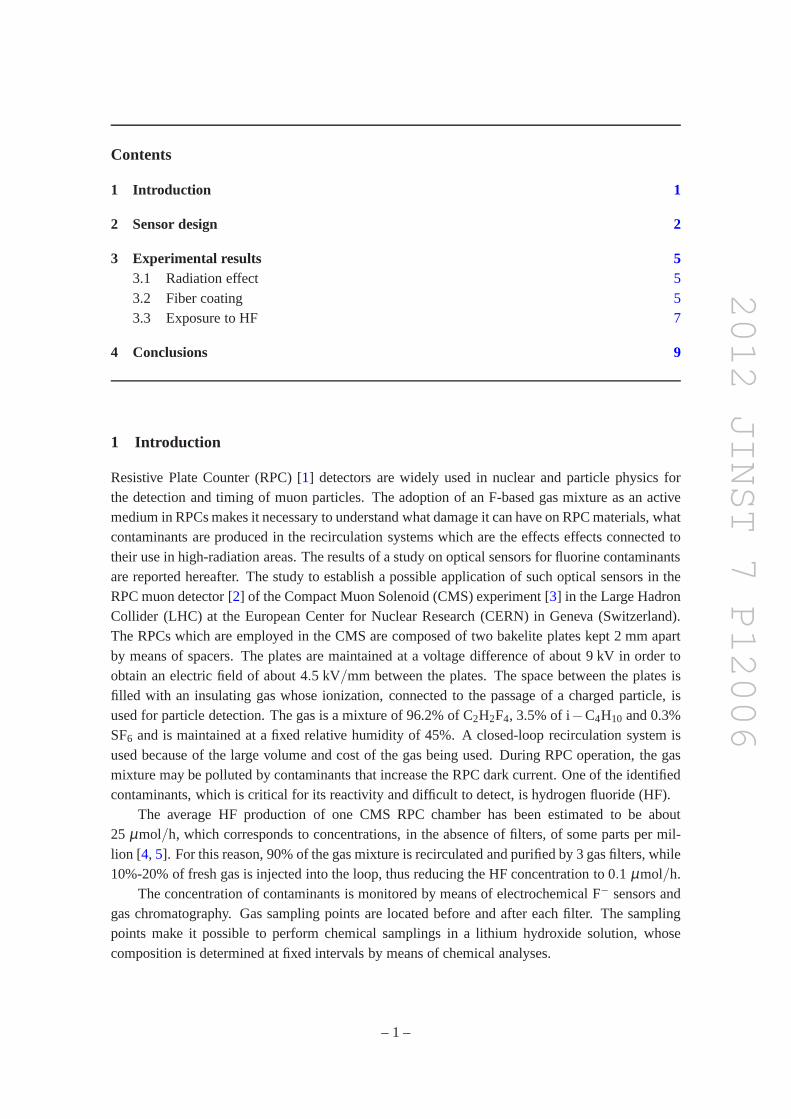
The fibers were processed onto the ground electrode at the floating temperature reached bythe plasma which was kept below 70C in order to avoid damaging the PMMA core Thanks tothe high conformability of the plasma discharge the entire surface exposed to the plasma can becoated except for the point in contact with the ground electrode The depositions were performedtherefore in two steps reversing the fiber half way to cover the entire surface thus obtaining auniform thickness In order to assess the conformability ofthe plasma discharge some deposi-tion experiments were performed onto Si patterned wafer specimens which demonstrated the goodhomogeneity of the coating thickness (see figure2) As an example figure2 shows a Field Emis-sion Scanning Electron Microscope (FESEM) image of a deposited film which has a structure thatclosely resembles the amorphous structure of glass The figure shows how the thickness of a filmwith average thickness of 145 nm has a variability of no more than 20 nm between horizontal andvertical surfaces
Finally the LED PD and the connections were painted with a black HF resistant paint to avoidproblems due to the effect of environmental light andor of the light which could travel from LEDto the PD outside the fiber
The described procedure allows one to obtain rather cheap assemblies but has two main draw-backs First the initial transmission capability is closely connected to the position of the LEDPDholes with respect to the cupola centers and is also affected to a great extent by the polishing ofthe fiber ends These problems could lead to rather differentPD currents even in the presenceof a fixed LED current and therefore the PD conditioning circuit should have a variable gain tocompensate for this variability However if all the measurements are scaled to the initial transmit-tance the mounting effect can be rendered unimportant Thesecond more important drawback isconnected to the different expansion ratios of the fiber and the fiber support This results in fiberstretching andor bending which can have an effect on the transmission capability of about 5 fortemperature changes of 5C This is not a problem in the RPC use since the temperature is con-trolled and the temperature changes are usually lower than 1C however a new setup is currentlybeing designed in which a different bonding solution is employed in order to reduce the effect ofthe changes in temperature
ndash 4 ndash
2012 JINST 7 P12006
Figure 2 FESEM image of the cross-section of the SiOx film deposited onto a Si patterned wafer The coat-ing thickness is quite homegeneous in the range of 124 nm to 164 nm demonstrating the good conformabilityof the plasma discharge
3 Experimental results
31 Radiation effect
Since the sensors are designed to be employed in the presenceof high-energy radiations it isimportant to assess the behavior of the plastic fiber the LED and the PD when exposed to suchradiations Studies are in fact available regarding the behavior of glass fibers in the presence ofradiation [19ndash21] but few results are available regarding plastic fibers [22] In general high energyradiations can produce fiber depolymerization that could reduce the transparency of the fiber thusimpairing the performance of the sensor According to the results described in [22] the expectedchange is of about 1 dBm for a PMMA fiber excited with a red wavelength and subjected to adose of 100 Gy This corresponds to an amplitude change of theorder of 5 on a 10 cm longfiber in the same conditions while negligible changes should be recorded for doses of the order of1 Gy which are the values expected in the fiber installation position for several months of CMSoperation To test this effect two sensor assemblies one using a bare fiber and one with a fibercoated with a silver thin film were installed and left in place for about six months in the GammaIrradiation Facility (GIF) at CERN The silver layer was chosen because it can easily be depositedvia plasma it can react with fluoride vapors and it can lead to the formation silver fluoride (AgF)which due to its yellow color can alter the light transmittance of the fiber This kind of coatingwas not used in the final sensors since it is sensitive to many other pollutants and provides limitedsensitivity [14]
After this period which corresponds to a dose of about 2 Gy no changes in the transmissionratio were recorded on the bare fiber while a small transmission reduction of the order of 5 wasobserved for the silver coated fiber probably because of a slight tarnishing caused by the reactionbetween the silver film and the atmosphere
32 Fiber coating
ndash 5 ndash
2012 JINST 7 P12006
Figure 3 Example of dark field pictures of a fiber coated with a thick layer of SiOx (400 nm) Top imageuncoated fiber middle image the SiOx coated fiber bottom image SiOx coated fiber after exposure toHF vapors
When the fiber is coated according to the procedure describedin the previous section two pa-rameters must be considered the gas composition and the deposition time The gas compositiondetermines the nature of the coating ie the organicinorganic nature of the SiOx layer Since theobjective is to obtain a layer with a high refractive index aglass-like film is desired and this re-sults in the deposition in an oxygen rich plasma in order to reduce the organic fraction of the filmThe authors therefore employed a TEOS O2 Ar = 1 20 20 sccm mixture which allows one toobtain a mostly inorganic SiOx film as confirmed by the FTIR
The deposition time determines the coating thickness a toothin layer leads to an insufficientdispersive effect while a too thick layer can reduce the received light to a very low value andproduce a sensor with extremely low sensitivity since the fluoride attack cannot completely destroythe film
An Si specimen was inserted into the plasma reactor along with the fiber to allow easy mea-surement of the film thickness by means of an FESEM Figure3 shows as an example dark fieldpictures of a fiber coated with a 400 nm thick SiOx film obtained after a deposition time of 30 minThe top image shows the fiber core The light dispersion is minimal and is due to the roughnessof the fiber as a consequence of the cladding removal The middle picture shows the same fiberafter the SiOx film deposition the layer which is quite thick makes the fiber highly dispersive sothat the light barely reaches the photodiode The bottom image shows the fiber after exposure toHF vapors as described in the following section In the latter case the fiber is less dispersive butstill barely any light reaches the photodiode as the thick SiOx is only partially attacked by the acidvapors Figure4 instead shows dark field pictures of a fiber coated with a 200 nmthick SiOx filmobtained after a deposition time of 15 min
The top picture shows the bare fiber with a small slight dispersion and is similar to the resultof figure3 The middle image shows the dispersion increase due to the 200 nm film although lesschange can be observed than in the case of figure3 since the layer is thinner A small amount oflight is still able to reach the end of the fiber The bottom picture taken after exposure to the HFvapors shows degradation of the glass-like 200 nm film which results in a reduced dispersionso that the light at the end of the fiber significantly increases compared to the coated unexposedfiber For these reasons the POF sensor prototypes developed in this study have been coated witha 200 nm thick SiOx film
ndash 6 ndash
2012 JINST 7 P12006
Figure 4 Example of dark field pictures of a fiber coated with a thin SiOx film (200 nm) Top imageuncoated fiber middle image fiber after coating bottom image coated fiber after exposure to HF vapors
Figure 5 Block diagram of the measurement setup which comprises thesensor assembly a T sensor ((RSPlatinum Thin Film class APt100) a DMM-scanner and a PC connected to the scanner via IEEE488 in-terface The reaction chamber is made of polytetrafluoroethylene (PTFE) which is HF-resistant The HFvapors are generated by inserting a small PTFE bowl containing a calibrated solution of HF into the reac-tion chamber
33 Exposure to HF
The effect of HF on the SiOx coated POF sensor has been investigated by employing the measuringsetup shown in figure5 The sensor assembly is enclosed in a polytetrafluoroethylene (PTFE)chamber which can be sealed completely A T sensor (RS Platinum Thin Film class APt100) is alsoinserted into the chamber and used to monitor the temperature HF vapor generation is obtained byusing a small PFTE bowl containing a few milliliters of HF solutions with different concentrationsThis way it is possible to create HF vapors with different partial pressure by simply changingthe concentration of the HF solution The partial pressure can be computed using the Antoineequation [23] and the coefficients can be found either on the NIST web site [24] or computed frompartial pressure experimental measurements [25]
The exposure tests were performed by employing a 40 in volume HF certified solution Thesolution was diluted to 20 in volume which corresponds to apartial pressure of about 700 Pa ata temperature of about 25C All the tests were performed leaving the fiber in the bowl for somehours in clean air and then inserting the PTFE bowl with the HFsolution into the chamber andleaving the measurement running until the fiber output reached a plateau
ndash 7 ndash
2012 JINST 7 P12006
Figure 6 Coated fiber response to HF exposure From top Temperatureduring the test measured with theT sensor HF vapor concentration computed according to the Antoine equation exposure computed as theintegral of the vapor concentration fiber transmittance ratio normalized to its initial value The test whichlasted more than two days was conducted in a uncontrolled environment in which the temperature duringthe test changes in the range of 22C to 27C only the first 30 hours are shown as the transmission ratioreaches a plateau after about 25 hours The fiber has an outputthat follows the exposure until saturationwhich appears when the transmission ratio increases about 3times
Figure6 shows as an example the result of an exposure test The figure shows the temperaturemeasured by the T sensor the HF vapor concentration computed using the Antoine equation afterthe HF bowl had been inserted into the chamber after about fivehours during which the fiber signalreached stability The two lower traces show the exposure computed as the integral of the vaporconcentration and the fiber transmittance ratio normalizedto its initial value The test which lastedabout two days was conducted in an uncontrolled environment in which the temperature during thetest changed in the range of 22C to 27C The picture shows the first 30 hours during which thefiber has an output that follows the exposure until saturation which appears when the transmissionratio increases about 3 times After about 25 hours the transmission ratio reaches a plateau
An FESEM analysis of the SiOx film (figure7) shows the film morphology after the HF attackThe SiOx coated fiber surface can be observed on the left before HF exposurewhile the imagestaken after exposure at different magnification levels canbe seen in the center and on the rightBefore exposure the SiOx film appears smooth and homogeneous while it is extensivelycorrodedafter exposure to the aggressive atmosphere and thus loosespart of its dispersing capability
Finally figure8 shows the exposure estimated from the fiber output using the equation
E = kf (Rminus1) (31)
whereR is the fiber transmittance normalized to its initial value and kf is the transmittance sensi-tivity identified on the basis of experimental data which has a value of about 7000(ppmmiddothour)minus1
ndash 8 ndash
2012 JINST 7 P12006
Figure 7 FESEM images of the coated fiber before (left) and after (center and right) exposure to theHF vapors
Figure 8 Exposure estimated on the basis of the sensor output and difference with respect to the expectedvalue The difference remains within 400 ppmmiddothour until the sensor reaches the end of life after exposureof about 10000 ppmmiddothour
The blue line in the figure is the ideal expected response while the red line is the measuredresponse the difference between the estimated and expected exposure can be observed at the bot-ton The difference remains within 400 ppmmiddothour until the sensor reaches the end of the life afterexposure of about 10000 ppmmiddothour
4 Conclusions
A new cumulative sensor prototype which can be used to monitor the presence of HF in gas mix-tures employed in RPCs has been designed The sensor which can be obtained by coating a plasticoptical fiber with a thin SiOx layer deposited by means of PECVD shows a high selectivity withrespect to the fluoride ions and has a cost of the sensitive part of few dollars The experimentsdescribed in this paper have shown that the light transmitted by the fiber changes as soon as theSiOx is attacked by HF vapors in particular changes of 3 times after exposition of 15000 ppm
ndash 9 ndash
2012 JINST 7 P12006
per hour have been observed The sensor has also been testedfor operability in the presence ofhigh-energy radiations and no changes have been observed when the sensor was exposed to a doseof about 2 Gy This makes it possible to conclude that it couldbe employed in the RPC for longerperiods than six months without any radiation-induced degradation The sensor could be equippedeither with a wireless battery-operated controller to avoid wire connections or with a standard ac-quisition system if electromagnetic interferences have tobe avoided The sensors are still sensitiveto environmental conditions which limits their accuracy and this is mainly due to the procedureadopted to mount the assembly A new mounting structure is currently being designed in order toreduce this problem however the low cost of this sensor andits ability to work in the presenceof high energy radiations make it a promising solution for large-scale continuous monitoring forexperiments employing a large number of RPCs such as in the CMS site
References
[1] R Santonico and R CardarelliDevelopment of resistive plate countersNucl Instrum Meth187 (1981) 377
[2] A Colaleo et alFirst measurements of the performance of the barrel RPC system in CMSNucl Instrum MethA 609 (2009) 114
[3] CMS collabroation S Chatrchyan et alThe CMS experiment at the CERN LHC2006JINST3 S08004
[4] M Abbrescia et alResults about HF production and bakelite analysis for the CMS resistive platechambers Nucl Instrum Meth594 (2008) 140
[5] L Benussi et alStudy of gas purifiers for the CMS RPC detectorNucl Instrum Meth661 (2011) 241[arXiv10125511]
[6] VP Chviruk OV Linuycheva and EM ZaverachGalvanic-type electrochemical sensor fordetermining the content of hydrohalogens in the air Sensors ActuatorB 92 (2003) 60
[7] F Bergera JB Sancheza and O HeintzbDetection of hydrogen fluoride using SnO2-based gassensors understanding of the reactional mechanism Sensors ActuatorB 143 (2009) 152
[8] S Kaciulis et alInvestigation of thin films of mixed oxides for gas-sensing applicationsSurf Interface Anal34 (2002) 672
[9] Y Suna L Chena F Zhangb D Li H Pana and J YecFirst-principles studies of HF moleculeadsorption on intrinsic graphene and Al-doped graphene Solid State Commun150 (2010) 1906
[10] JA BuckFundamentals of optical fibers 2nd edition Wiley and Sons Inc New York USA(2004)
[11] J Zubia and J ArruePlastic optical fibers an introduction to their technological processes andapplication Opt Fiber Technol7 (2001) 101
[12] U SteigerSensor properties and applications of POFs in proceedings of 7th InternationalConference on Plastic Optical Fibres and Applications (POF98) October 5ndash8 Berlin Germany(1998)
[13] G Durana et alUse of a novel fiber optical strain sensor for monitoring the vertical deflection of anaircraft flap IEEE Sensors J9 (2009) 1219
ndash 10 ndash
2012 JINST 7 P12006
[14] S Corbellini et alModified POF sensor for gaseous hydrogen fluoride monitoringin the presence ofionizing radiations IEEE Trans Instrum Meas61 (2012) 1201
[15] O Ziemann et alPOF Handbook mdash Optical short range transmission systems 2nd edition SpringerUSA (2008)
[16] B Ruchti et alDevelopment of new scintillating fiber detectors for high energy physics applicationsIEEE Trans Nucl Sci36 (1989) 146
[17] G Perrone and A VallanA low-cost optical sensor for non contact vibration measurementsIEEE Trans Instrum Meas58 (2009) 1650
[18] E Angelini et alPlastic optic fiber sensor for cumulative measurementsin the proceeding of theInternational Conference on Instrumentation and Measurements (I2MTC2009) May 5ndash7 Singapore(2009)
[19] RH West and S DowlingMeasurement of long term radiation induced losses in fibre optics usingoptical time domain reflectometry IEEE Trans Nucl Sci39 (1992) 418
[20] H Liu DW Miller and J TalnagiGamma radiation resistant Fabry-Perot fiber optic sensorsRev Sci Instrum73 (2002) 3112
[21] WH Hardwick and AH KalmaEffects of low-dose-rate radiation on opto-electronic componentsand the consequences upon fiber optic data link performance IEEE Trans Nucl Sci26 (1979) 4808
[22] B ChironThe behaviour of POF under nuclear radiation applicationsfor nuclear detectorscintillators data transmission amp illumination IEE Colloq Plast Mater Opt Trans5 (1989) 1
[23] C AntoineTensions des vapeurs nouvelle relation entre les tensionset les tempe Compt RendAcad Sci107 (1888)
[24] httpwebbooknistgovchemistry (Sept 2011)
[25] Hydrofluoric acid properties available athttphoneywellcom (Sept 2011)
[26] M Tomozawa and T TakamorizRelation of surface structure of glass to HF acid attack and stressstate J Amer Ceram Soc62 (1979) 370
ndash 11 ndash
- Introduction
- Sensor design
- Experimental results
-
- Radiation effect
- Fiber coating
- Exposure to HF
-
- Conclusions
-
2012 JINST 7 P12006
PUBLISHED BY IOP PUBLISHING FOR SISSA MEDIALAB
RECEIVED July 30 2012ACCEPTED October 30 2012
PUBLISHED December 7 2012
SPECIAL ISSUE ON RESISTIVE PLATE CHAMBERS AND RELATED DETECTORS RPC2012
Gas monitoring in RPC by means of non-invasiveplasma coated POF sensors
S Grassinia1 M Ishtaiwib M Parvisb L Benussic S Biancoc S Colafranceschic
and D Piccoloc
aDipartimento di Scienza Applicata e Tecnologia Politecnico di TorinoCorso Duca degli Abruzzi 24 Torino Italy
bDipartimento di Elettronica e Telecomunicazioni Politecnico di TorinoCorso Duca degli Abruzzi 24 Torino Italy
cLaboratori Nazionali di Frascati dellrsquoINFNv E Fermi 40 Frascati 00044 Italy
E-mail sabrinagrassinipolitoit
ABSTRACT Resistive Plate Counters (RPC) are employed as muon detectors in many high-ratehigh-energy physics experiments such as the Compact Muon Solenoid (CMS) experiment cur-rently under way in the Large Hadron Collider (LHC) accelerator at the European Center for Nu-clear Research (CERN) A gas mixture containing C2H2F4 iminusC4H10 and SF6 is recirculated insidethe RPCs during their use and subjected to degradation due tothe production of fluoride ions whichlimits the sensitivity of the RPCs This paper describes a new sensor that is able to detect low con-centrations of fluoride ions in gas mixtures The sensor is made of a plastic optic fiber (POF) whichis made sensitive to Fminus gaseous ions by means of a thin layer of a glass-like material depositedvia plasma onto the fiber core The Fminus ions attack the glass-like film and alter the transmissioncapability of the fiber so that the detection simply requiresa LED and a photodiode The sensorexploits a cumulative response which makes it suitable for direct estimation of the total exposureto the Fminus ions thus providing a tool that can be used to tune the maintenance of the gas filters Theglass-like film is deposited by means of plasma enhanced chemical vapor deposition (PECVD) oforganosilicons monomers which allows the deposition to beperformed a low temperature in orderto avoid damaging the fiber core
KEYWORDS Gaseous detectors Gas systems and purification Resistive-plate chambers
1Corresponding author
ccopy 2012 IOP Publishing Ltd and Sissa Medialab srl doi1010881748-0221712P12006
2012 JINST 7 P12006
Contents
1 Introduction 1
2 Sensor design 2
3 Experimental results 531 Radiation effect 532 Fiber coating 533 Exposure to HF 7
4 Conclusions 9
1 Introduction
Resistive Plate Counter (RPC) [1] detectors are widely used in nuclear and particle physics forthe detection and timing of muon particles The adoption of an F-based gas mixture as an activemedium in RPCs makes it necessary to understand what damage it can have on RPC materials whatcontaminants are produced in the recirculation systems which are the effects effects connected totheir use in high-radiation areas The results of a study on optical sensors for fluorine contaminantsare reported hereafter The study to establish a possible application of such optical sensors in theRPC muon detector [2] of the Compact Muon Solenoid (CMS) experiment [3] in the Large HadronCollider (LHC) at the European Center for Nuclear Research (CERN) in Geneva (Switzerland)The RPCs which are employed in the CMS are composed of two bakelite plates kept 2 mm apartby means of spacers The plates are maintained at a voltage difference of about 9 kV in order toobtain an electric field of about 45 kVmm between the plates The space between the plates isfilled with an insulating gas whose ionization connected tothe passage of a charged particle isused for particle detection The gas is a mixture of 962 of C2H2F4 35 of iminusC4H10 and 03SF6 and is maintained at a fixed relative humidity of 45 A closed-loop recirculation system isused because of the large volume and cost of the gas being used During RPC operation the gasmixture may be polluted by contaminants that increase the RPC dark current One of the identifiedcontaminants which is critical for its reactivity and difficult to detect is hydrogen fluoride (HF)
The average HF production of one CMS RPC chamber has been estimated to be about25 micromolh which corresponds to concentrations in the absence of filters of some parts per mil-lion [4 5] For this reason 90 of the gas mixture is recirculated andpurified by 3 gas filters while10-20 of fresh gas is injected into the loop thus reducingthe HF concentration to 01 micromolh
The concentration of contaminants is monitored by means of electrochemical Fminus sensors andgas chromatography Gas sampling points are located beforeand after each filter The samplingpoints make it possible to perform chemical samplings in a lithium hydroxide solution whosecomposition is determined at fixed intervals by means of chemical analyses
ndash 1 ndash
2012 JINST 7 P12006
Figure 1 Sensor assembly with LED fiber and PD
Commercially available sensors for fluoride ion detection (eg galvanic-type sensors that arebased on MnO2 gas-diffusion electrodes [6]) have a measuring range of 10minus20 ppm which is toohigh for this kind of measurement These commercial Hydrogen Fluoride sensors (eg from CEAInstruments Inc GasDetectors USA) are designed for personal safety and have costs in excess of500$ per unit so that their massive use for a complete RPC monitoring is not feasible
More sensitive sensors such as tin dioxide and Al-doped graphene based devices [7ndash9] havebeen proposed to detect hydrogen fluoride traces at part-per-billion concentration but they all havea higher cost
Intrinsic sensors based on Plastic Optical Fibers (POFs) made of poly-methyl-methacrylate(PMMA) [10 11] could be an interesting alternative provided they can be made sensitive tofluoride ions The use of POFs for sensing applications is rapidly growing [12ndash14] because ofthe cost-effectiveness of the POFs and the easiness of use connected to their large diameters(025 mmminus1 mm) which permit simple and cheap plastic connectors to beused while still main-taining a good optical coupling [15] Fiber optics can be used to develop intrinsic sensors thanksto several different principles (fiber grating scintillation light attenuation changes due to pollutantabsorbtion in the core light losses due to fiber bending etc [16 17]) However POFs offer theadvantage of having a remarkable evanescent field which extends outside the core and which canbe used to develop sensors based on the propagation loss change that occurs due to the interactionof the evanescent field with the surrounding media
2 Sensor design
A fiber based sensor that exploits the interaction of the evanescent field with the surrounding envi-ronment can easily be arranged with a structure composed of alight emitting diode an optic fiberand a photodiode as shown in figure1
The fiber has a length of about 10 cm The used LED (Kingbright L-53SRD-G) emits in thevisible red region (wavelength 635 nmndash680 nm) and has been selected since PMMA has a stableattenuation value in the red region [22] when exposed to radiations A wide band photodiode(Osram SFH 213) is also employed
Both LED and PD cupolas are drilled with 1 mm holes the fiber isinserted into the holes andbonded to the components using liquid PMMA The fiber is then cured in an oven at 60C for threedays to ensure complete polymerization of the liquid PMMA Finally the assembly is bonded to aPVC support so that the fiber is retained in a fixed position
ndash 2 ndash
2012 JINST 7 P12006
In order to exploit the use of the evanescent field the POF cladding must be removed and thecore exposed so that the sensitive film can directly interactwith the evanescent field
Commercially available fibers commonly used for telecommunication purposes costing about1$ per meter can be employed to develop the sensor These fibers are step-index highlymulti-mode POFs with a 098 mm diameter PMMA core surrounded by a 001 mm fluoropoly-mer cladding
The cladding can be removed either by means of a mechanical process or by means of a chem-ical process The mechanical approach is difficult to carry out without damaging the core which iscomposed of PMMA that is a relatively soft material on the other hand a pure chemical approachis not feasible since the long exposure to the solvent that isnecessary to obtain the complete dis-solution of the fluoropolymer would damage the core For thisreasonthe authors have employeda mixed chemico-mechanical approach Initially the fiber is dipped into ethylacetate for 40 s sothat the fluoropolymer is attacked then the cladding is stripped using a soft paper towel which isable to remove the fluoropolymer without damaging the core
Once the cladding has been removed the sensitive film must bedeposited using a low temper-ature process since the PMMA core is damaged at temperaturehigher than 80C A good solutionwhich also allows a precise control of the layer structure tobe obtained is the use of low pressureplasma treatments or rsquocold plasmasrsquo Plasma Enhanced Chemical Vapor Deposition (PECVD) canbe used to develop very sensitive sensors [18] PECVD modifies the fiber surface properties eitherby grafting different functional groups or by depositing thin films whose physico-chemical andoptical properties can be changed over a broad range simply by making a proper selection of theexperimental parameters
The critical aspect in the design of a POF sensor that exploits the evanescent field and itsinteraction with the surrounding media in order to achieve sensitivity to the quantity of interestconcerns the selection of the sensitive film The film that hasto be deposited on the fiber coremust be capable of reacting with the sensed quantity of interest with a reaction which alters thecapability of the fiber of transmitting the light In addition to achieve the required selectivitythe film must have a minimal reacting capability with respectto other quantities present in thesurrounding environment which could also affect the lighttransmission
This selectivity can easily been obtained in the case of fluoride ions by employing a glass-like thin film Glass has a higher refractive index than the PMMA and thus affects light transmis-sion to a great extent It is attacked by the Fminus ions and is almost unaffected by other quantitiesTwo problems arise first the direct deposition of glass ontothe fiber is impossible since the melt-ing temperature of glass is much higher than the melting temperature of PMMA second a carefulcontrol of the glass thickness is fundamental to obtain goodinteraction with the evanescent fieldIt is important to note that the reaction between glass and fluoride ions is not reversible and leadsto the formation of silicon tetrafluoride (SiF4)
SiO2+4HFrArr SiF4 +2H2O (21)
The developed sensor shows intrinsic cumulative behaviorie the sensor output is propor-tional to the integral of the exposure to the HF vapors When coupled to conventional sensors forthe detection of other contaminants such as O2 N2 H2O the sensor will provide a direct measure-ment of the residual purifier lifetime The cumulative mode of operation requires that the sensorshould be discarded after use thus dictating the need for a cheap product
ndash 3 ndash
2012 JINST 7 P12006
The fiber can therefore be coated with an SiOx film which has a very similar composition andamorphous structure to glass SiOx thin films with thicknesses of up to a few hundred nanome-ters can easily be deposited on the POF surface by means of PECVD starting from organosili-con monomers
The plastic fibers were therefore treated in a plasma fed withtetraethoxysilane (TEOS) O2and Ar in different ratios The plasma discharge was performed at a pressure of 5 Pa and with aninput power of 50 W The thickness of the deposited SiOx film can be changed simply by varyingthe deposition time
The PECVD reactor employed in this study consists of a stainless steel vacuum chamber con-nected to a turbomolecular pump backed up by a rotary pump A 1kW 1356 MHz RF powergenerator connected through an impedance matching unit is used to ignite the discharge A throt-tle valve and a pressure gauge permit the chamber pressure tobe controlled Four injection linesequipped with mass flow controllers permit quaternary discharge gas mixtures to be used A sepa-rate controller is used for the injection of the film precursor vapor
The fibers were processed onto the ground electrode at the floating temperature reached bythe plasma which was kept below 70C in order to avoid damaging the PMMA core Thanks tothe high conformability of the plasma discharge the entire surface exposed to the plasma can becoated except for the point in contact with the ground electrode The depositions were performedtherefore in two steps reversing the fiber half way to cover the entire surface thus obtaining auniform thickness In order to assess the conformability ofthe plasma discharge some deposi-tion experiments were performed onto Si patterned wafer specimens which demonstrated the goodhomogeneity of the coating thickness (see figure2) As an example figure2 shows a Field Emis-sion Scanning Electron Microscope (FESEM) image of a deposited film which has a structure thatclosely resembles the amorphous structure of glass The figure shows how the thickness of a filmwith average thickness of 145 nm has a variability of no more than 20 nm between horizontal andvertical surfaces
Finally the LED PD and the connections were painted with a black HF resistant paint to avoidproblems due to the effect of environmental light andor of the light which could travel from LEDto the PD outside the fiber
The described procedure allows one to obtain rather cheap assemblies but has two main draw-backs First the initial transmission capability is closely connected to the position of the LEDPDholes with respect to the cupola centers and is also affected to a great extent by the polishing ofthe fiber ends These problems could lead to rather differentPD currents even in the presenceof a fixed LED current and therefore the PD conditioning circuit should have a variable gain tocompensate for this variability However if all the measurements are scaled to the initial transmit-tance the mounting effect can be rendered unimportant Thesecond more important drawback isconnected to the different expansion ratios of the fiber and the fiber support This results in fiberstretching andor bending which can have an effect on the transmission capability of about 5 fortemperature changes of 5C This is not a problem in the RPC use since the temperature is con-trolled and the temperature changes are usually lower than 1C however a new setup is currentlybeing designed in which a different bonding solution is employed in order to reduce the effect ofthe changes in temperature
ndash 4 ndash
2012 JINST 7 P12006
Figure 2 FESEM image of the cross-section of the SiOx film deposited onto a Si patterned wafer The coat-ing thickness is quite homegeneous in the range of 124 nm to 164 nm demonstrating the good conformabilityof the plasma discharge
3 Experimental results
31 Radiation effect
Since the sensors are designed to be employed in the presenceof high-energy radiations it isimportant to assess the behavior of the plastic fiber the LED and the PD when exposed to suchradiations Studies are in fact available regarding the behavior of glass fibers in the presence ofradiation [19ndash21] but few results are available regarding plastic fibers [22] In general high energyradiations can produce fiber depolymerization that could reduce the transparency of the fiber thusimpairing the performance of the sensor According to the results described in [22] the expectedchange is of about 1 dBm for a PMMA fiber excited with a red wavelength and subjected to adose of 100 Gy This corresponds to an amplitude change of theorder of 5 on a 10 cm longfiber in the same conditions while negligible changes should be recorded for doses of the order of1 Gy which are the values expected in the fiber installation position for several months of CMSoperation To test this effect two sensor assemblies one using a bare fiber and one with a fibercoated with a silver thin film were installed and left in place for about six months in the GammaIrradiation Facility (GIF) at CERN The silver layer was chosen because it can easily be depositedvia plasma it can react with fluoride vapors and it can lead to the formation silver fluoride (AgF)which due to its yellow color can alter the light transmittance of the fiber This kind of coatingwas not used in the final sensors since it is sensitive to many other pollutants and provides limitedsensitivity [14]
After this period which corresponds to a dose of about 2 Gy no changes in the transmissionratio were recorded on the bare fiber while a small transmission reduction of the order of 5 wasobserved for the silver coated fiber probably because of a slight tarnishing caused by the reactionbetween the silver film and the atmosphere
32 Fiber coating
ndash 5 ndash
2012 JINST 7 P12006
Figure 3 Example of dark field pictures of a fiber coated with a thick layer of SiOx (400 nm) Top imageuncoated fiber middle image the SiOx coated fiber bottom image SiOx coated fiber after exposure toHF vapors
When the fiber is coated according to the procedure describedin the previous section two pa-rameters must be considered the gas composition and the deposition time The gas compositiondetermines the nature of the coating ie the organicinorganic nature of the SiOx layer Since theobjective is to obtain a layer with a high refractive index aglass-like film is desired and this re-sults in the deposition in an oxygen rich plasma in order to reduce the organic fraction of the filmThe authors therefore employed a TEOS O2 Ar = 1 20 20 sccm mixture which allows one toobtain a mostly inorganic SiOx film as confirmed by the FTIR
The deposition time determines the coating thickness a toothin layer leads to an insufficientdispersive effect while a too thick layer can reduce the received light to a very low value andproduce a sensor with extremely low sensitivity since the fluoride attack cannot completely destroythe film
An Si specimen was inserted into the plasma reactor along with the fiber to allow easy mea-surement of the film thickness by means of an FESEM Figure3 shows as an example dark fieldpictures of a fiber coated with a 400 nm thick SiOx film obtained after a deposition time of 30 minThe top image shows the fiber core The light dispersion is minimal and is due to the roughnessof the fiber as a consequence of the cladding removal The middle picture shows the same fiberafter the SiOx film deposition the layer which is quite thick makes the fiber highly dispersive sothat the light barely reaches the photodiode The bottom image shows the fiber after exposure toHF vapors as described in the following section In the latter case the fiber is less dispersive butstill barely any light reaches the photodiode as the thick SiOx is only partially attacked by the acidvapors Figure4 instead shows dark field pictures of a fiber coated with a 200 nmthick SiOx filmobtained after a deposition time of 15 min
The top picture shows the bare fiber with a small slight dispersion and is similar to the resultof figure3 The middle image shows the dispersion increase due to the 200 nm film although lesschange can be observed than in the case of figure3 since the layer is thinner A small amount oflight is still able to reach the end of the fiber The bottom picture taken after exposure to the HFvapors shows degradation of the glass-like 200 nm film which results in a reduced dispersionso that the light at the end of the fiber significantly increases compared to the coated unexposedfiber For these reasons the POF sensor prototypes developed in this study have been coated witha 200 nm thick SiOx film
ndash 6 ndash
2012 JINST 7 P12006
Figure 4 Example of dark field pictures of a fiber coated with a thin SiOx film (200 nm) Top imageuncoated fiber middle image fiber after coating bottom image coated fiber after exposure to HF vapors
Figure 5 Block diagram of the measurement setup which comprises thesensor assembly a T sensor ((RSPlatinum Thin Film class APt100) a DMM-scanner and a PC connected to the scanner via IEEE488 in-terface The reaction chamber is made of polytetrafluoroethylene (PTFE) which is HF-resistant The HFvapors are generated by inserting a small PTFE bowl containing a calibrated solution of HF into the reac-tion chamber
33 Exposure to HF
The effect of HF on the SiOx coated POF sensor has been investigated by employing the measuringsetup shown in figure5 The sensor assembly is enclosed in a polytetrafluoroethylene (PTFE)chamber which can be sealed completely A T sensor (RS Platinum Thin Film class APt100) is alsoinserted into the chamber and used to monitor the temperature HF vapor generation is obtained byusing a small PFTE bowl containing a few milliliters of HF solutions with different concentrationsThis way it is possible to create HF vapors with different partial pressure by simply changingthe concentration of the HF solution The partial pressure can be computed using the Antoineequation [23] and the coefficients can be found either on the NIST web site [24] or computed frompartial pressure experimental measurements [25]
The exposure tests were performed by employing a 40 in volume HF certified solution Thesolution was diluted to 20 in volume which corresponds to apartial pressure of about 700 Pa ata temperature of about 25C All the tests were performed leaving the fiber in the bowl for somehours in clean air and then inserting the PTFE bowl with the HFsolution into the chamber andleaving the measurement running until the fiber output reached a plateau
ndash 7 ndash
2012 JINST 7 P12006
Figure 6 Coated fiber response to HF exposure From top Temperatureduring the test measured with theT sensor HF vapor concentration computed according to the Antoine equation exposure computed as theintegral of the vapor concentration fiber transmittance ratio normalized to its initial value The test whichlasted more than two days was conducted in a uncontrolled environment in which the temperature duringthe test changes in the range of 22C to 27C only the first 30 hours are shown as the transmission ratioreaches a plateau after about 25 hours The fiber has an outputthat follows the exposure until saturationwhich appears when the transmission ratio increases about 3times
Figure6 shows as an example the result of an exposure test The figure shows the temperaturemeasured by the T sensor the HF vapor concentration computed using the Antoine equation afterthe HF bowl had been inserted into the chamber after about fivehours during which the fiber signalreached stability The two lower traces show the exposure computed as the integral of the vaporconcentration and the fiber transmittance ratio normalizedto its initial value The test which lastedabout two days was conducted in an uncontrolled environment in which the temperature during thetest changed in the range of 22C to 27C The picture shows the first 30 hours during which thefiber has an output that follows the exposure until saturation which appears when the transmissionratio increases about 3 times After about 25 hours the transmission ratio reaches a plateau
An FESEM analysis of the SiOx film (figure7) shows the film morphology after the HF attackThe SiOx coated fiber surface can be observed on the left before HF exposurewhile the imagestaken after exposure at different magnification levels canbe seen in the center and on the rightBefore exposure the SiOx film appears smooth and homogeneous while it is extensivelycorrodedafter exposure to the aggressive atmosphere and thus loosespart of its dispersing capability
Finally figure8 shows the exposure estimated from the fiber output using the equation
E = kf (Rminus1) (31)
whereR is the fiber transmittance normalized to its initial value and kf is the transmittance sensi-tivity identified on the basis of experimental data which has a value of about 7000(ppmmiddothour)minus1
ndash 8 ndash
2012 JINST 7 P12006
Figure 7 FESEM images of the coated fiber before (left) and after (center and right) exposure to theHF vapors
Figure 8 Exposure estimated on the basis of the sensor output and difference with respect to the expectedvalue The difference remains within 400 ppmmiddothour until the sensor reaches the end of life after exposureof about 10000 ppmmiddothour
The blue line in the figure is the ideal expected response while the red line is the measuredresponse the difference between the estimated and expected exposure can be observed at the bot-ton The difference remains within 400 ppmmiddothour until the sensor reaches the end of the life afterexposure of about 10000 ppmmiddothour
4 Conclusions
A new cumulative sensor prototype which can be used to monitor the presence of HF in gas mix-tures employed in RPCs has been designed The sensor which can be obtained by coating a plasticoptical fiber with a thin SiOx layer deposited by means of PECVD shows a high selectivity withrespect to the fluoride ions and has a cost of the sensitive part of few dollars The experimentsdescribed in this paper have shown that the light transmitted by the fiber changes as soon as theSiOx is attacked by HF vapors in particular changes of 3 times after exposition of 15000 ppm
ndash 9 ndash
2012 JINST 7 P12006
per hour have been observed The sensor has also been testedfor operability in the presence ofhigh-energy radiations and no changes have been observed when the sensor was exposed to a doseof about 2 Gy This makes it possible to conclude that it couldbe employed in the RPC for longerperiods than six months without any radiation-induced degradation The sensor could be equippedeither with a wireless battery-operated controller to avoid wire connections or with a standard ac-quisition system if electromagnetic interferences have tobe avoided The sensors are still sensitiveto environmental conditions which limits their accuracy and this is mainly due to the procedureadopted to mount the assembly A new mounting structure is currently being designed in order toreduce this problem however the low cost of this sensor andits ability to work in the presenceof high energy radiations make it a promising solution for large-scale continuous monitoring forexperiments employing a large number of RPCs such as in the CMS site
References
[1] R Santonico and R CardarelliDevelopment of resistive plate countersNucl Instrum Meth187 (1981) 377
[2] A Colaleo et alFirst measurements of the performance of the barrel RPC system in CMSNucl Instrum MethA 609 (2009) 114
[3] CMS collabroation S Chatrchyan et alThe CMS experiment at the CERN LHC2006JINST3 S08004
[4] M Abbrescia et alResults about HF production and bakelite analysis for the CMS resistive platechambers Nucl Instrum Meth594 (2008) 140
[5] L Benussi et alStudy of gas purifiers for the CMS RPC detectorNucl Instrum Meth661 (2011) 241[arXiv10125511]
[6] VP Chviruk OV Linuycheva and EM ZaverachGalvanic-type electrochemical sensor fordetermining the content of hydrohalogens in the air Sensors ActuatorB 92 (2003) 60
[7] F Bergera JB Sancheza and O HeintzbDetection of hydrogen fluoride using SnO2-based gassensors understanding of the reactional mechanism Sensors ActuatorB 143 (2009) 152
[8] S Kaciulis et alInvestigation of thin films of mixed oxides for gas-sensing applicationsSurf Interface Anal34 (2002) 672
[9] Y Suna L Chena F Zhangb D Li H Pana and J YecFirst-principles studies of HF moleculeadsorption on intrinsic graphene and Al-doped graphene Solid State Commun150 (2010) 1906
[10] JA BuckFundamentals of optical fibers 2nd edition Wiley and Sons Inc New York USA(2004)
[11] J Zubia and J ArruePlastic optical fibers an introduction to their technological processes andapplication Opt Fiber Technol7 (2001) 101
[12] U SteigerSensor properties and applications of POFs in proceedings of 7th InternationalConference on Plastic Optical Fibres and Applications (POF98) October 5ndash8 Berlin Germany(1998)
[13] G Durana et alUse of a novel fiber optical strain sensor for monitoring the vertical deflection of anaircraft flap IEEE Sensors J9 (2009) 1219
ndash 10 ndash
2012 JINST 7 P12006
[14] S Corbellini et alModified POF sensor for gaseous hydrogen fluoride monitoringin the presence ofionizing radiations IEEE Trans Instrum Meas61 (2012) 1201
[15] O Ziemann et alPOF Handbook mdash Optical short range transmission systems 2nd edition SpringerUSA (2008)
[16] B Ruchti et alDevelopment of new scintillating fiber detectors for high energy physics applicationsIEEE Trans Nucl Sci36 (1989) 146
[17] G Perrone and A VallanA low-cost optical sensor for non contact vibration measurementsIEEE Trans Instrum Meas58 (2009) 1650
[18] E Angelini et alPlastic optic fiber sensor for cumulative measurementsin the proceeding of theInternational Conference on Instrumentation and Measurements (I2MTC2009) May 5ndash7 Singapore(2009)
[19] RH West and S DowlingMeasurement of long term radiation induced losses in fibre optics usingoptical time domain reflectometry IEEE Trans Nucl Sci39 (1992) 418
[20] H Liu DW Miller and J TalnagiGamma radiation resistant Fabry-Perot fiber optic sensorsRev Sci Instrum73 (2002) 3112
[21] WH Hardwick and AH KalmaEffects of low-dose-rate radiation on opto-electronic componentsand the consequences upon fiber optic data link performance IEEE Trans Nucl Sci26 (1979) 4808
[22] B ChironThe behaviour of POF under nuclear radiation applicationsfor nuclear detectorscintillators data transmission amp illumination IEE Colloq Plast Mater Opt Trans5 (1989) 1
[23] C AntoineTensions des vapeurs nouvelle relation entre les tensionset les tempe Compt RendAcad Sci107 (1888)
[24] httpwebbooknistgovchemistry (Sept 2011)
[25] Hydrofluoric acid properties available athttphoneywellcom (Sept 2011)
[26] M Tomozawa and T TakamorizRelation of surface structure of glass to HF acid attack and stressstate J Amer Ceram Soc62 (1979) 370
ndash 11 ndash
- Introduction
- Sensor design
- Experimental results
-
- Radiation effect
- Fiber coating
- Exposure to HF
-
- Conclusions
-
2012 JINST 7 P12006
Contents
1 Introduction 1
2 Sensor design 2
3 Experimental results 531 Radiation effect 532 Fiber coating 533 Exposure to HF 7
4 Conclusions 9
1 Introduction
Resistive Plate Counter (RPC) [1] detectors are widely used in nuclear and particle physics forthe detection and timing of muon particles The adoption of an F-based gas mixture as an activemedium in RPCs makes it necessary to understand what damage it can have on RPC materials whatcontaminants are produced in the recirculation systems which are the effects effects connected totheir use in high-radiation areas The results of a study on optical sensors for fluorine contaminantsare reported hereafter The study to establish a possible application of such optical sensors in theRPC muon detector [2] of the Compact Muon Solenoid (CMS) experiment [3] in the Large HadronCollider (LHC) at the European Center for Nuclear Research (CERN) in Geneva (Switzerland)The RPCs which are employed in the CMS are composed of two bakelite plates kept 2 mm apartby means of spacers The plates are maintained at a voltage difference of about 9 kV in order toobtain an electric field of about 45 kVmm between the plates The space between the plates isfilled with an insulating gas whose ionization connected tothe passage of a charged particle isused for particle detection The gas is a mixture of 962 of C2H2F4 35 of iminusC4H10 and 03SF6 and is maintained at a fixed relative humidity of 45 A closed-loop recirculation system isused because of the large volume and cost of the gas being used During RPC operation the gasmixture may be polluted by contaminants that increase the RPC dark current One of the identifiedcontaminants which is critical for its reactivity and difficult to detect is hydrogen fluoride (HF)
The average HF production of one CMS RPC chamber has been estimated to be about25 micromolh which corresponds to concentrations in the absence of filters of some parts per mil-lion [4 5] For this reason 90 of the gas mixture is recirculated andpurified by 3 gas filters while10-20 of fresh gas is injected into the loop thus reducingthe HF concentration to 01 micromolh
The concentration of contaminants is monitored by means of electrochemical Fminus sensors andgas chromatography Gas sampling points are located beforeand after each filter The samplingpoints make it possible to perform chemical samplings in a lithium hydroxide solution whosecomposition is determined at fixed intervals by means of chemical analyses
ndash 1 ndash
2012 JINST 7 P12006
Figure 1 Sensor assembly with LED fiber and PD
Commercially available sensors for fluoride ion detection (eg galvanic-type sensors that arebased on MnO2 gas-diffusion electrodes [6]) have a measuring range of 10minus20 ppm which is toohigh for this kind of measurement These commercial Hydrogen Fluoride sensors (eg from CEAInstruments Inc GasDetectors USA) are designed for personal safety and have costs in excess of500$ per unit so that their massive use for a complete RPC monitoring is not feasible
More sensitive sensors such as tin dioxide and Al-doped graphene based devices [7ndash9] havebeen proposed to detect hydrogen fluoride traces at part-per-billion concentration but they all havea higher cost
Intrinsic sensors based on Plastic Optical Fibers (POFs) made of poly-methyl-methacrylate(PMMA) [10 11] could be an interesting alternative provided they can be made sensitive tofluoride ions The use of POFs for sensing applications is rapidly growing [12ndash14] because ofthe cost-effectiveness of the POFs and the easiness of use connected to their large diameters(025 mmminus1 mm) which permit simple and cheap plastic connectors to beused while still main-taining a good optical coupling [15] Fiber optics can be used to develop intrinsic sensors thanksto several different principles (fiber grating scintillation light attenuation changes due to pollutantabsorbtion in the core light losses due to fiber bending etc [16 17]) However POFs offer theadvantage of having a remarkable evanescent field which extends outside the core and which canbe used to develop sensors based on the propagation loss change that occurs due to the interactionof the evanescent field with the surrounding media
2 Sensor design
A fiber based sensor that exploits the interaction of the evanescent field with the surrounding envi-ronment can easily be arranged with a structure composed of alight emitting diode an optic fiberand a photodiode as shown in figure1
The fiber has a length of about 10 cm The used LED (Kingbright L-53SRD-G) emits in thevisible red region (wavelength 635 nmndash680 nm) and has been selected since PMMA has a stableattenuation value in the red region [22] when exposed to radiations A wide band photodiode(Osram SFH 213) is also employed
Both LED and PD cupolas are drilled with 1 mm holes the fiber isinserted into the holes andbonded to the components using liquid PMMA The fiber is then cured in an oven at 60C for threedays to ensure complete polymerization of the liquid PMMA Finally the assembly is bonded to aPVC support so that the fiber is retained in a fixed position
ndash 2 ndash
2012 JINST 7 P12006
In order to exploit the use of the evanescent field the POF cladding must be removed and thecore exposed so that the sensitive film can directly interactwith the evanescent field
Commercially available fibers commonly used for telecommunication purposes costing about1$ per meter can be employed to develop the sensor These fibers are step-index highlymulti-mode POFs with a 098 mm diameter PMMA core surrounded by a 001 mm fluoropoly-mer cladding
The cladding can be removed either by means of a mechanical process or by means of a chem-ical process The mechanical approach is difficult to carry out without damaging the core which iscomposed of PMMA that is a relatively soft material on the other hand a pure chemical approachis not feasible since the long exposure to the solvent that isnecessary to obtain the complete dis-solution of the fluoropolymer would damage the core For thisreasonthe authors have employeda mixed chemico-mechanical approach Initially the fiber is dipped into ethylacetate for 40 s sothat the fluoropolymer is attacked then the cladding is stripped using a soft paper towel which isable to remove the fluoropolymer without damaging the core
Once the cladding has been removed the sensitive film must bedeposited using a low temper-ature process since the PMMA core is damaged at temperaturehigher than 80C A good solutionwhich also allows a precise control of the layer structure tobe obtained is the use of low pressureplasma treatments or rsquocold plasmasrsquo Plasma Enhanced Chemical Vapor Deposition (PECVD) canbe used to develop very sensitive sensors [18] PECVD modifies the fiber surface properties eitherby grafting different functional groups or by depositing thin films whose physico-chemical andoptical properties can be changed over a broad range simply by making a proper selection of theexperimental parameters
The critical aspect in the design of a POF sensor that exploits the evanescent field and itsinteraction with the surrounding media in order to achieve sensitivity to the quantity of interestconcerns the selection of the sensitive film The film that hasto be deposited on the fiber coremust be capable of reacting with the sensed quantity of interest with a reaction which alters thecapability of the fiber of transmitting the light In addition to achieve the required selectivitythe film must have a minimal reacting capability with respectto other quantities present in thesurrounding environment which could also affect the lighttransmission
This selectivity can easily been obtained in the case of fluoride ions by employing a glass-like thin film Glass has a higher refractive index than the PMMA and thus affects light transmis-sion to a great extent It is attacked by the Fminus ions and is almost unaffected by other quantitiesTwo problems arise first the direct deposition of glass ontothe fiber is impossible since the melt-ing temperature of glass is much higher than the melting temperature of PMMA second a carefulcontrol of the glass thickness is fundamental to obtain goodinteraction with the evanescent fieldIt is important to note that the reaction between glass and fluoride ions is not reversible and leadsto the formation of silicon tetrafluoride (SiF4)
SiO2+4HFrArr SiF4 +2H2O (21)
The developed sensor shows intrinsic cumulative behaviorie the sensor output is propor-tional to the integral of the exposure to the HF vapors When coupled to conventional sensors forthe detection of other contaminants such as O2 N2 H2O the sensor will provide a direct measure-ment of the residual purifier lifetime The cumulative mode of operation requires that the sensorshould be discarded after use thus dictating the need for a cheap product
ndash 3 ndash
2012 JINST 7 P12006
The fiber can therefore be coated with an SiOx film which has a very similar composition andamorphous structure to glass SiOx thin films with thicknesses of up to a few hundred nanome-ters can easily be deposited on the POF surface by means of PECVD starting from organosili-con monomers
The plastic fibers were therefore treated in a plasma fed withtetraethoxysilane (TEOS) O2and Ar in different ratios The plasma discharge was performed at a pressure of 5 Pa and with aninput power of 50 W The thickness of the deposited SiOx film can be changed simply by varyingthe deposition time
The PECVD reactor employed in this study consists of a stainless steel vacuum chamber con-nected to a turbomolecular pump backed up by a rotary pump A 1kW 1356 MHz RF powergenerator connected through an impedance matching unit is used to ignite the discharge A throt-tle valve and a pressure gauge permit the chamber pressure tobe controlled Four injection linesequipped with mass flow controllers permit quaternary discharge gas mixtures to be used A sepa-rate controller is used for the injection of the film precursor vapor
The fibers were processed onto the ground electrode at the floating temperature reached bythe plasma which was kept below 70C in order to avoid damaging the PMMA core Thanks tothe high conformability of the plasma discharge the entire surface exposed to the plasma can becoated except for the point in contact with the ground electrode The depositions were performedtherefore in two steps reversing the fiber half way to cover the entire surface thus obtaining auniform thickness In order to assess the conformability ofthe plasma discharge some deposi-tion experiments were performed onto Si patterned wafer specimens which demonstrated the goodhomogeneity of the coating thickness (see figure2) As an example figure2 shows a Field Emis-sion Scanning Electron Microscope (FESEM) image of a deposited film which has a structure thatclosely resembles the amorphous structure of glass The figure shows how the thickness of a filmwith average thickness of 145 nm has a variability of no more than 20 nm between horizontal andvertical surfaces
Finally the LED PD and the connections were painted with a black HF resistant paint to avoidproblems due to the effect of environmental light andor of the light which could travel from LEDto the PD outside the fiber
The described procedure allows one to obtain rather cheap assemblies but has two main draw-backs First the initial transmission capability is closely connected to the position of the LEDPDholes with respect to the cupola centers and is also affected to a great extent by the polishing ofthe fiber ends These problems could lead to rather differentPD currents even in the presenceof a fixed LED current and therefore the PD conditioning circuit should have a variable gain tocompensate for this variability However if all the measurements are scaled to the initial transmit-tance the mounting effect can be rendered unimportant Thesecond more important drawback isconnected to the different expansion ratios of the fiber and the fiber support This results in fiberstretching andor bending which can have an effect on the transmission capability of about 5 fortemperature changes of 5C This is not a problem in the RPC use since the temperature is con-trolled and the temperature changes are usually lower than 1C however a new setup is currentlybeing designed in which a different bonding solution is employed in order to reduce the effect ofthe changes in temperature
ndash 4 ndash
2012 JINST 7 P12006
Figure 2 FESEM image of the cross-section of the SiOx film deposited onto a Si patterned wafer The coat-ing thickness is quite homegeneous in the range of 124 nm to 164 nm demonstrating the good conformabilityof the plasma discharge
3 Experimental results
31 Radiation effect
Since the sensors are designed to be employed in the presenceof high-energy radiations it isimportant to assess the behavior of the plastic fiber the LED and the PD when exposed to suchradiations Studies are in fact available regarding the behavior of glass fibers in the presence ofradiation [19ndash21] but few results are available regarding plastic fibers [22] In general high energyradiations can produce fiber depolymerization that could reduce the transparency of the fiber thusimpairing the performance of the sensor According to the results described in [22] the expectedchange is of about 1 dBm for a PMMA fiber excited with a red wavelength and subjected to adose of 100 Gy This corresponds to an amplitude change of theorder of 5 on a 10 cm longfiber in the same conditions while negligible changes should be recorded for doses of the order of1 Gy which are the values expected in the fiber installation position for several months of CMSoperation To test this effect two sensor assemblies one using a bare fiber and one with a fibercoated with a silver thin film were installed and left in place for about six months in the GammaIrradiation Facility (GIF) at CERN The silver layer was chosen because it can easily be depositedvia plasma it can react with fluoride vapors and it can lead to the formation silver fluoride (AgF)which due to its yellow color can alter the light transmittance of the fiber This kind of coatingwas not used in the final sensors since it is sensitive to many other pollutants and provides limitedsensitivity [14]
After this period which corresponds to a dose of about 2 Gy no changes in the transmissionratio were recorded on the bare fiber while a small transmission reduction of the order of 5 wasobserved for the silver coated fiber probably because of a slight tarnishing caused by the reactionbetween the silver film and the atmosphere
32 Fiber coating
ndash 5 ndash
2012 JINST 7 P12006
Figure 3 Example of dark field pictures of a fiber coated with a thick layer of SiOx (400 nm) Top imageuncoated fiber middle image the SiOx coated fiber bottom image SiOx coated fiber after exposure toHF vapors
When the fiber is coated according to the procedure describedin the previous section two pa-rameters must be considered the gas composition and the deposition time The gas compositiondetermines the nature of the coating ie the organicinorganic nature of the SiOx layer Since theobjective is to obtain a layer with a high refractive index aglass-like film is desired and this re-sults in the deposition in an oxygen rich plasma in order to reduce the organic fraction of the filmThe authors therefore employed a TEOS O2 Ar = 1 20 20 sccm mixture which allows one toobtain a mostly inorganic SiOx film as confirmed by the FTIR
The deposition time determines the coating thickness a toothin layer leads to an insufficientdispersive effect while a too thick layer can reduce the received light to a very low value andproduce a sensor with extremely low sensitivity since the fluoride attack cannot completely destroythe film
An Si specimen was inserted into the plasma reactor along with the fiber to allow easy mea-surement of the film thickness by means of an FESEM Figure3 shows as an example dark fieldpictures of a fiber coated with a 400 nm thick SiOx film obtained after a deposition time of 30 minThe top image shows the fiber core The light dispersion is minimal and is due to the roughnessof the fiber as a consequence of the cladding removal The middle picture shows the same fiberafter the SiOx film deposition the layer which is quite thick makes the fiber highly dispersive sothat the light barely reaches the photodiode The bottom image shows the fiber after exposure toHF vapors as described in the following section In the latter case the fiber is less dispersive butstill barely any light reaches the photodiode as the thick SiOx is only partially attacked by the acidvapors Figure4 instead shows dark field pictures of a fiber coated with a 200 nmthick SiOx filmobtained after a deposition time of 15 min
The top picture shows the bare fiber with a small slight dispersion and is similar to the resultof figure3 The middle image shows the dispersion increase due to the 200 nm film although lesschange can be observed than in the case of figure3 since the layer is thinner A small amount oflight is still able to reach the end of the fiber The bottom picture taken after exposure to the HFvapors shows degradation of the glass-like 200 nm film which results in a reduced dispersionso that the light at the end of the fiber significantly increases compared to the coated unexposedfiber For these reasons the POF sensor prototypes developed in this study have been coated witha 200 nm thick SiOx film
ndash 6 ndash
2012 JINST 7 P12006
Figure 4 Example of dark field pictures of a fiber coated with a thin SiOx film (200 nm) Top imageuncoated fiber middle image fiber after coating bottom image coated fiber after exposure to HF vapors
Figure 5 Block diagram of the measurement setup which comprises thesensor assembly a T sensor ((RSPlatinum Thin Film class APt100) a DMM-scanner and a PC connected to the scanner via IEEE488 in-terface The reaction chamber is made of polytetrafluoroethylene (PTFE) which is HF-resistant The HFvapors are generated by inserting a small PTFE bowl containing a calibrated solution of HF into the reac-tion chamber
33 Exposure to HF
The effect of HF on the SiOx coated POF sensor has been investigated by employing the measuringsetup shown in figure5 The sensor assembly is enclosed in a polytetrafluoroethylene (PTFE)chamber which can be sealed completely A T sensor (RS Platinum Thin Film class APt100) is alsoinserted into the chamber and used to monitor the temperature HF vapor generation is obtained byusing a small PFTE bowl containing a few milliliters of HF solutions with different concentrationsThis way it is possible to create HF vapors with different partial pressure by simply changingthe concentration of the HF solution The partial pressure can be computed using the Antoineequation [23] and the coefficients can be found either on the NIST web site [24] or computed frompartial pressure experimental measurements [25]
The exposure tests were performed by employing a 40 in volume HF certified solution Thesolution was diluted to 20 in volume which corresponds to apartial pressure of about 700 Pa ata temperature of about 25C All the tests were performed leaving the fiber in the bowl for somehours in clean air and then inserting the PTFE bowl with the HFsolution into the chamber andleaving the measurement running until the fiber output reached a plateau
ndash 7 ndash
2012 JINST 7 P12006
Figure 6 Coated fiber response to HF exposure From top Temperatureduring the test measured with theT sensor HF vapor concentration computed according to the Antoine equation exposure computed as theintegral of the vapor concentration fiber transmittance ratio normalized to its initial value The test whichlasted more than two days was conducted in a uncontrolled environment in which the temperature duringthe test changes in the range of 22C to 27C only the first 30 hours are shown as the transmission ratioreaches a plateau after about 25 hours The fiber has an outputthat follows the exposure until saturationwhich appears when the transmission ratio increases about 3times
Figure6 shows as an example the result of an exposure test The figure shows the temperaturemeasured by the T sensor the HF vapor concentration computed using the Antoine equation afterthe HF bowl had been inserted into the chamber after about fivehours during which the fiber signalreached stability The two lower traces show the exposure computed as the integral of the vaporconcentration and the fiber transmittance ratio normalizedto its initial value The test which lastedabout two days was conducted in an uncontrolled environment in which the temperature during thetest changed in the range of 22C to 27C The picture shows the first 30 hours during which thefiber has an output that follows the exposure until saturation which appears when the transmissionratio increases about 3 times After about 25 hours the transmission ratio reaches a plateau
An FESEM analysis of the SiOx film (figure7) shows the film morphology after the HF attackThe SiOx coated fiber surface can be observed on the left before HF exposurewhile the imagestaken after exposure at different magnification levels canbe seen in the center and on the rightBefore exposure the SiOx film appears smooth and homogeneous while it is extensivelycorrodedafter exposure to the aggressive atmosphere and thus loosespart of its dispersing capability
Finally figure8 shows the exposure estimated from the fiber output using the equation
E = kf (Rminus1) (31)
whereR is the fiber transmittance normalized to its initial value and kf is the transmittance sensi-tivity identified on the basis of experimental data which has a value of about 7000(ppmmiddothour)minus1
ndash 8 ndash
2012 JINST 7 P12006
Figure 7 FESEM images of the coated fiber before (left) and after (center and right) exposure to theHF vapors
Figure 8 Exposure estimated on the basis of the sensor output and difference with respect to the expectedvalue The difference remains within 400 ppmmiddothour until the sensor reaches the end of life after exposureof about 10000 ppmmiddothour
The blue line in the figure is the ideal expected response while the red line is the measuredresponse the difference between the estimated and expected exposure can be observed at the bot-ton The difference remains within 400 ppmmiddothour until the sensor reaches the end of the life afterexposure of about 10000 ppmmiddothour
4 Conclusions
A new cumulative sensor prototype which can be used to monitor the presence of HF in gas mix-tures employed in RPCs has been designed The sensor which can be obtained by coating a plasticoptical fiber with a thin SiOx layer deposited by means of PECVD shows a high selectivity withrespect to the fluoride ions and has a cost of the sensitive part of few dollars The experimentsdescribed in this paper have shown that the light transmitted by the fiber changes as soon as theSiOx is attacked by HF vapors in particular changes of 3 times after exposition of 15000 ppm
ndash 9 ndash
2012 JINST 7 P12006
per hour have been observed The sensor has also been testedfor operability in the presence ofhigh-energy radiations and no changes have been observed when the sensor was exposed to a doseof about 2 Gy This makes it possible to conclude that it couldbe employed in the RPC for longerperiods than six months without any radiation-induced degradation The sensor could be equippedeither with a wireless battery-operated controller to avoid wire connections or with a standard ac-quisition system if electromagnetic interferences have tobe avoided The sensors are still sensitiveto environmental conditions which limits their accuracy and this is mainly due to the procedureadopted to mount the assembly A new mounting structure is currently being designed in order toreduce this problem however the low cost of this sensor andits ability to work in the presenceof high energy radiations make it a promising solution for large-scale continuous monitoring forexperiments employing a large number of RPCs such as in the CMS site
References
[1] R Santonico and R CardarelliDevelopment of resistive plate countersNucl Instrum Meth187 (1981) 377
[2] A Colaleo et alFirst measurements of the performance of the barrel RPC system in CMSNucl Instrum MethA 609 (2009) 114
[3] CMS collabroation S Chatrchyan et alThe CMS experiment at the CERN LHC2006JINST3 S08004
[4] M Abbrescia et alResults about HF production and bakelite analysis for the CMS resistive platechambers Nucl Instrum Meth594 (2008) 140
[5] L Benussi et alStudy of gas purifiers for the CMS RPC detectorNucl Instrum Meth661 (2011) 241[arXiv10125511]
[6] VP Chviruk OV Linuycheva and EM ZaverachGalvanic-type electrochemical sensor fordetermining the content of hydrohalogens in the air Sensors ActuatorB 92 (2003) 60
[7] F Bergera JB Sancheza and O HeintzbDetection of hydrogen fluoride using SnO2-based gassensors understanding of the reactional mechanism Sensors ActuatorB 143 (2009) 152
[8] S Kaciulis et alInvestigation of thin films of mixed oxides for gas-sensing applicationsSurf Interface Anal34 (2002) 672
[9] Y Suna L Chena F Zhangb D Li H Pana and J YecFirst-principles studies of HF moleculeadsorption on intrinsic graphene and Al-doped graphene Solid State Commun150 (2010) 1906
[10] JA BuckFundamentals of optical fibers 2nd edition Wiley and Sons Inc New York USA(2004)
[11] J Zubia and J ArruePlastic optical fibers an introduction to their technological processes andapplication Opt Fiber Technol7 (2001) 101
[12] U SteigerSensor properties and applications of POFs in proceedings of 7th InternationalConference on Plastic Optical Fibres and Applications (POF98) October 5ndash8 Berlin Germany(1998)
[13] G Durana et alUse of a novel fiber optical strain sensor for monitoring the vertical deflection of anaircraft flap IEEE Sensors J9 (2009) 1219
ndash 10 ndash
2012 JINST 7 P12006
[14] S Corbellini et alModified POF sensor for gaseous hydrogen fluoride monitoringin the presence ofionizing radiations IEEE Trans Instrum Meas61 (2012) 1201
[15] O Ziemann et alPOF Handbook mdash Optical short range transmission systems 2nd edition SpringerUSA (2008)
[16] B Ruchti et alDevelopment of new scintillating fiber detectors for high energy physics applicationsIEEE Trans Nucl Sci36 (1989) 146
[17] G Perrone and A VallanA low-cost optical sensor for non contact vibration measurementsIEEE Trans Instrum Meas58 (2009) 1650
[18] E Angelini et alPlastic optic fiber sensor for cumulative measurementsin the proceeding of theInternational Conference on Instrumentation and Measurements (I2MTC2009) May 5ndash7 Singapore(2009)
[19] RH West and S DowlingMeasurement of long term radiation induced losses in fibre optics usingoptical time domain reflectometry IEEE Trans Nucl Sci39 (1992) 418
[20] H Liu DW Miller and J TalnagiGamma radiation resistant Fabry-Perot fiber optic sensorsRev Sci Instrum73 (2002) 3112
[21] WH Hardwick and AH KalmaEffects of low-dose-rate radiation on opto-electronic componentsand the consequences upon fiber optic data link performance IEEE Trans Nucl Sci26 (1979) 4808
[22] B ChironThe behaviour of POF under nuclear radiation applicationsfor nuclear detectorscintillators data transmission amp illumination IEE Colloq Plast Mater Opt Trans5 (1989) 1
[23] C AntoineTensions des vapeurs nouvelle relation entre les tensionset les tempe Compt RendAcad Sci107 (1888)
[24] httpwebbooknistgovchemistry (Sept 2011)
[25] Hydrofluoric acid properties available athttphoneywellcom (Sept 2011)
[26] M Tomozawa and T TakamorizRelation of surface structure of glass to HF acid attack and stressstate J Amer Ceram Soc62 (1979) 370
ndash 11 ndash
- Introduction
- Sensor design
- Experimental results
-
- Radiation effect
- Fiber coating
- Exposure to HF
-
- Conclusions
-

2012 JINST 7 P12006
[14] S Corbellini et alModified POF sensor for gaseous hydrogen fluoride monitoringin the presence ofionizing radiations IEEE Trans Instrum Meas61 (2012) 1201
[15] O Ziemann et alPOF Handbook mdash Optical short range transmission systems 2nd edition SpringerUSA (2008)
[16] B Ruchti et alDevelopment of new scintillating fiber detectors for high energy physics applicationsIEEE Trans Nucl Sci36 (1989) 146
[17] G Perrone and A VallanA low-cost optical sensor for non contact vibration measurementsIEEE Trans Instrum Meas58 (2009) 1650
[18] E Angelini et alPlastic optic fiber sensor for cumulative measurementsin the proceeding of theInternational Conference on Instrumentation and Measurements (I2MTC2009) May 5ndash7 Singapore(2009)
[19] RH West and S DowlingMeasurement of long term radiation induced losses in fibre optics usingoptical time domain reflectometry IEEE Trans Nucl Sci39 (1992) 418
[20] H Liu DW Miller and J TalnagiGamma radiation resistant Fabry-Perot fiber optic sensorsRev Sci Instrum73 (2002) 3112
[21] WH Hardwick and AH KalmaEffects of low-dose-rate radiation on opto-electronic componentsand the consequences upon fiber optic data link performance IEEE Trans Nucl Sci26 (1979) 4808
[22] B ChironThe behaviour of POF under nuclear radiation applicationsfor nuclear detectorscintillators data transmission amp illumination IEE Colloq Plast Mater Opt Trans5 (1989) 1
[23] C AntoineTensions des vapeurs nouvelle relation entre les tensionset les tempe Compt RendAcad Sci107 (1888)
[24] httpwebbooknistgovchemistry (Sept 2011)
[25] Hydrofluoric acid properties available athttphoneywellcom (Sept 2011)
[26] M Tomozawa and T TakamorizRelation of surface structure of glass to HF acid attack and stressstate J Amer Ceram Soc62 (1979) 370
ndash 11 ndash
- Introduction
- Sensor design
- Experimental results
-
- Radiation effect
- Fiber coating
- Exposure to HF
-
- Conclusions
-