gas p100/mce-lx - gas p150/mce-lx · gas burners low nox two stages progressive or modulating...
TRANSCRIPT

GAS BURNERS LOW NOX TWO STAGES PROGRESSIVEOR MODULATING
SK073040_C_en
GAS P100/MCE-LX - GAS P150/MCE-LX
GAS BURNERS LOW NOX TWO STAGES PROGRESSIVE OR MODULATING
GAS P100/MCE-LX - GAS P150/MCE-LXBurners for gas two stages progressive (hi-low flame) or modulating (PID fully modulating) if equipped with additionof optional modulation kit and probe.They are composed by: die-cast aluminum body, fan at high pressurisation and combustion head with adjustment athigh efficiency and high flame stability.Compact overall dimensions and disposition rationalized of the components with accessibility facilitated for theoperations of setting and maintenance.Gas train completely assembled and tested; complete of working valve with flow adjustment, safety valve, minimumgas pressure switch and gas filter.Complete of flange and gasket for installation on generator.
Fig. 1 GAS P100/MCE-LX
Fig. 2 GAS P100/MCE-LX
Fig. 3 GAS P100/MCE-LX

GAS BURNERS LOW NOX TWO STAGES PROGRESSIVEOR MODULATING
SK073040_C_en
GAS P100/MCE-LX - GAS P150/MCE-LX
TECHNICAL DATA GAS P100/MCE-LX - GAS P150/MCE-LX
* Conditions of reference: Environment temperature 20°C - barometric pressure 1013 mbars - Altitude 0 m o.s.l.** To obtain this low Nox emission like in the declaration, it's necessary to couple the burner to the proper boiler for this application: boilers with 3turns for the exhaust gas, condensing boilers and any generator with direct exhaust outlet and the thermal load isn't higher then 1,1 MW/m³.*** Pressure of feeding of the gas to the ramp to get the maximum power of the burner considering against pressure in chamber of value combustion0 (zero).**** Measured sonorous pressure in the combustion laboratory , with functional burner on beta boiler to 1m of distance. (UNI EN ISO 3746).***** For burner with long head, add 3 kg to the weight.
OPERATING RANGE DIAGRAM
The firing rates has been obtained based on test boilers in accordance with EN267 standards and are indicative of matching the burner to the boiler.For the correct operation of the burner, combustion chamber dimensions must be in accordance with current regulation. In case of non-compliance,contact the manufacturer.
MODEL GAS P100/MCE-LX GAS P150/MCE-LX
Thermal power min. 1°st. / min. 2°st. - max. 2°st. * [Mcal/h] 133/400-851 230/700-1300
Thermal power min. 1°st. / min. 2°st. - max. 2°st. * [kW] 155/465-990 267/814-1511
Gas flow G20 (NATURAL GAS) min. 1°st. / min. 2°st. - max. 2°st. * [Nm³/h] 15.5/46.7-99.4 26.8/82-152
Fuel: NATURAL GAS (second family)
Fuel category: I2R,I2H,I2L,I2E,I2E+,I2Er,I2ELL,I2E(R)
NOx ** [mg/kWh] < 80: class 3 (EN 676)
Intermitted working operation (min. 1 stop every 24 hours) two stages progressive or modulating
Environmental conditions operation / storage: -15...+40°C / -20...+70°C, rel. humidity max. 80%
Max. temperature combustion air [°C] 60 60
Min. pressure gas train D1"1/2 - S NATURAL GAS *** [mbar] 41 -
Min. pressure gas train D2" - S NATURAL GAS *** [mbar] 36 56
Min. pressure gas train DN65-FS65 NATURAL GAS *** [mbar] 27 40
Min. pressure gas train DN80-FS80 NATURAL GAS *** [mbar] 25 32
Max. pressure at the entry of valves (Pe. max) [mbar] 360 360
Nominal electric power [kW] 2.7 3.4
Fan motor [kW] 2.2 3
Nominal motor current absorption [A] 5.4 6.4
Nominal auxiliary absorption [A] 0.5 0.6
Power supply: 3~400V, 1N~230V - 50Hz
Electric protection degree: IP 40 IP 40
Noisiness **** min. - max. [dB(A)] 81-82 83-84
Burner weight ***** [kg] 71 87
Fig. 4 X = Thermal power Y = Pression in the combustion chamber
GAS BURNERS LOW NOX TWO STAGES PROGRESSIVEOR MODULATING
SK073040_C_en
GAS P100/MCE-LX - GAS P150/MCE-LX
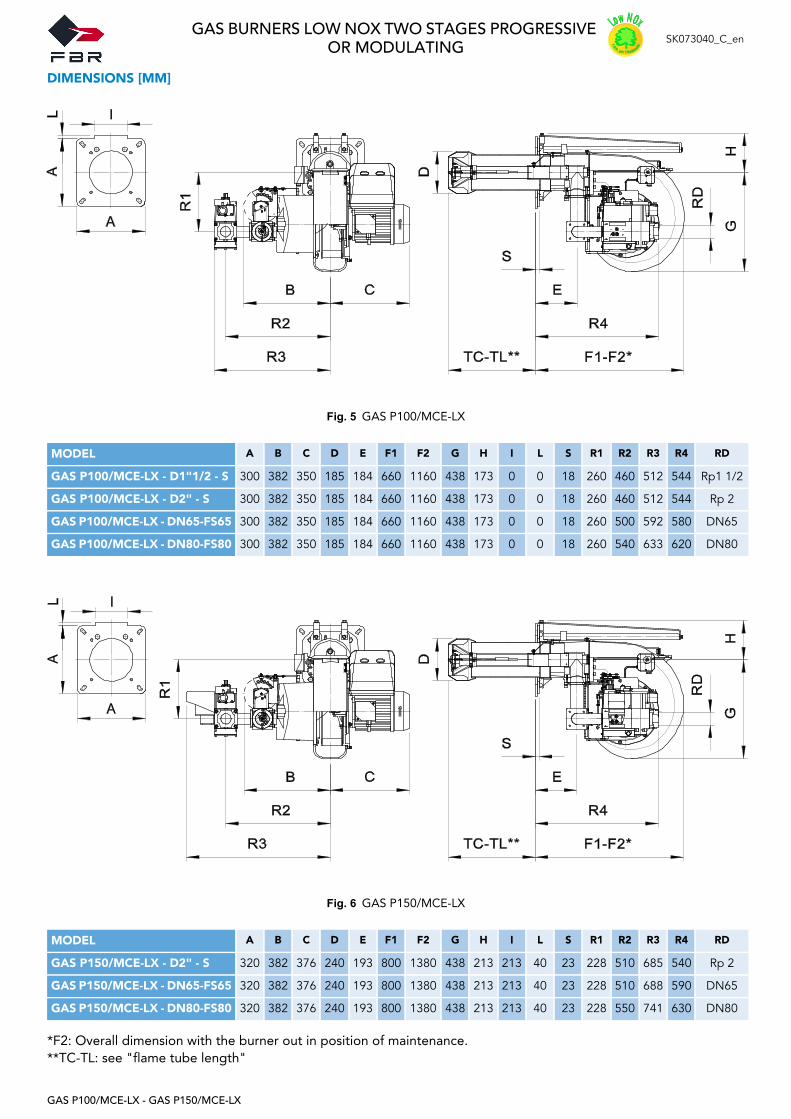
DIMENSIONS [MM]
*F2: Overall dimension with the burner out in position of maintenance.**TC-TL: see "flame tube length"
Fig. 5 GAS P100/MCE-LX
MODEL A B C D E F1 F2 G H I L S R1 R2 R3 R4 RD
GAS P100/MCE-LX - D1"1/2 - S 300 382 350 185 184 660 1160 438 173 0 0 18 260 460 512 544 Rp1 1/2
GAS P100/MCE-LX - D2" - S 300 382 350 185 184 660 1160 438 173 0 0 18 260 460 512 544 Rp 2
GAS P100/MCE-LX - DN65-FS65 300 382 350 185 184 660 1160 438 173 0 0 18 260 500 592 580 DN65
GAS P100/MCE-LX - DN80-FS80 300 382 350 185 184 660 1160 438 173 0 0 18 260 540 633 620 DN80
Fig. 6 GAS P150/MCE-LX
MODEL A B C D E F1 F2 G H I L S R1 R2 R3 R4 RD
GAS P150/MCE-LX - D2" - S 320 382 376 240 193 800 1380 438 213 213 40 23 228 510 685 540 Rp 2
GAS P150/MCE-LX - DN65-FS65 320 382 376 240 193 800 1380 438 213 213 40 23 228 510 688 590 DN65
GAS P150/MCE-LX - DN80-FS80 320 382 376 240 193 800 1380 438 213 213 40 23 228 550 741 630 DN80

GAS BURNERS LOW NOX TWO STAGES PROGRESSIVEOR MODULATING
SK073040_C_en
GAS P100/MCE-LX - GAS P150/MCE-LX
BOILER PLATE
FLAME TUBE LENGTH
Flame tube length must be selected based on the specifications supplied by boiler manufacturer and, in any case, itmust be greater than the thickness of the boiler door included its insulation.In case of boilers with flame inversion or front flue combustion chambers, it is necessary to insulate the area betweenthe flame tube and front door with refractory material. This protection material must not impede flame tube extraction.
** For different flame lengths, please contact our Technical-Sales Department.
Fig. 7 Boiler plate
MODEL P min P max M N min N max
GAS P100/MCE-LX mm 195 250 M12 340 368
GAS P150/MCE-LX mm 250 250 M14 340 368
MODEL TC TL **
GAS P100/MCE-LX mm 250 385
GAS P150/MCE-LX mm 280 400

GAS BURNERS LOW NOX TWO STAGES PROGRESSIVEOR MODULATING
SK073040_C_en
GAS P100/MCE-LX - GAS P150/MCE-LX
BURNER SIGNAL DESCRIPTION
In the picture below there are indicated all the signalation present on the burner:
* In the gas train DN65-FS65 and DN80-FS80 there are 2 lamps.
Fig. 8 Burner signal description
LEGEND
1) ON/OFF button
2) Reset from lockout button + status lamp
3) GAS valve lamp *
The multicolor signal lamp in the lockout reset button (pos.2) is the key indicating element for visual diagnosticsand interface diagnostics.In normal operation, the different operating states are indicated in the form of color codes; please refer toelectrical device handbook supplied with the present instructions.
After a non-alterable lockout, the red signal lamp in the lockout reset button (pos.2) lights up.By pressing the lockout reset button (pos.2) for more than 3 seconds, the visual diagnostics of the cause of faultcan be activated; please refer to electrical device handbook supplied with the present instructions.
For close the diagnostics mode and for switch on the burner again, it is necessary to reset the burner control.Press the lockout reset button (pos.2) for about 1 second (<3 seconds).
After a non-alterable lockout, the red signal lamp in the lockout reset button (pos.2) lights up.For reset the control box press the lockout reset button (pos.2) for about 1 second (<3 seconds).
12
3
GAS BURNERS LOW NOX TWO STAGES PROGRESSIVEOR MODULATING
SK073040_C_en
GAS P100/MCE-LX - GAS P150/MCE-LX
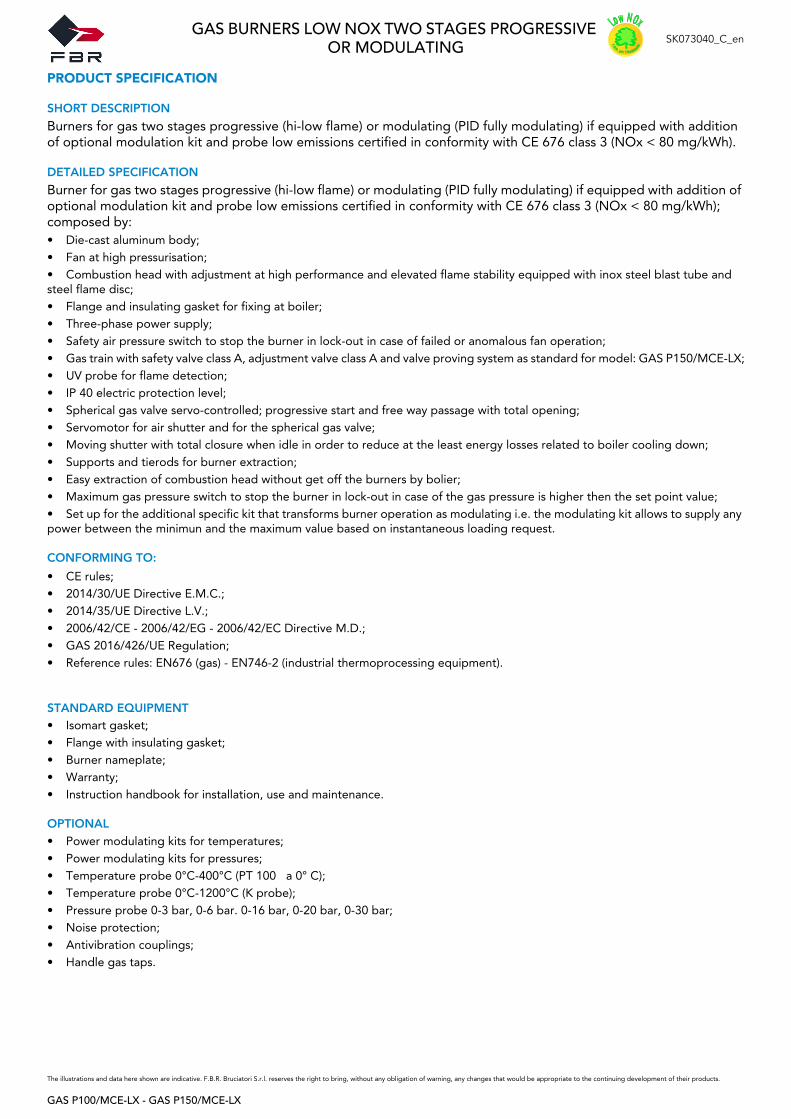
PRODUCT SPECIFICATION
SHORT DESCRIPTION
Burners for gas two stages progressive (hi-low flame) or modulating (PID fully modulating) if equipped with additionof optional modulation kit and probe low emissions certified in conformity with CE 676 class 3 (NOx < 80 mg/kWh).
DETAILED SPECIFICATION
Burner for gas two stages progressive (hi-low flame) or modulating (PID fully modulating) if equipped with addition ofoptional modulation kit and probe low emissions certified in conformity with CE 676 class 3 (NOx < 80 mg/kWh);composed by:• Die-cast aluminum body;• Fan at high pressurisation;• Combustion head with adjustment at high performance and elevated flame stability equipped with inox steel blast tube andsteel flame disc;• Flange and insulating gasket for fixing at boiler;• Three-phase power supply;• Safety air pressure switch to stop the burner in lock-out in case of failed or anomalous fan operation;• Gas train with safety valve class A, adjustment valve class A and valve proving system as standard for model: GAS P150/MCE-LX;• UV probe for flame detection;• IP 40 electric protection level;• Spherical gas valve servo-controlled; progressive start and free way passage with total opening;• Servomotor for air shutter and for the spherical gas valve;• Moving shutter with total closure when idle in order to reduce at the least energy losses related to boiler cooling down;• Supports and tierods for burner extraction;• Easy extraction of combustion head without get off the burners by bolier;• Maximum gas pressure switch to stop the burner in lock-out in case of the gas pressure is higher then the set point value;• Set up for the additional specific kit that transforms burner operation as modulating i.e. the modulating kit allows to supply anypower between the minimun and the maximum value based on instantaneous loading request.
CONFORMING TO:
STANDARD EQUIPMENT• Isomart gasket;• Flange with insulating gasket;• Burner nameplate;• Warranty;• Instruction handbook for installation, use and maintenance.
OPTIONAL• Power modulating kits for temperatures;• Power modulating kits for pressures;• Temperature probe 0°C-400°C (PT 100 a 0° C);• Temperature probe 0°C-1200°C (K probe);• Pressure probe 0-3 bar, 0-6 bar. 0-16 bar, 0-20 bar, 0-30 bar;• Noise protection;• Antivibration couplings;• Handle gas taps.
The illustrations and data here shown are indicative. F.B.R. Bruciatori S.r.l. reserves the right to bring, without any obligation of warning, any changes that would be appropriate to the continuing development of their products.
• CE rules;• 2014/30/UE Directive E.M.C.;• 2014/35/UE Directive L.V.;• 2006/42/CE - 2006/42/EG - 2006/42/EC Directive M.D.;• GAS 2016/426/UE Regulation;• Reference rules: EN676 (gas) - EN746-2 (industrial thermoprocessing equipment).