gateway energy centre
TRANSCRIPT
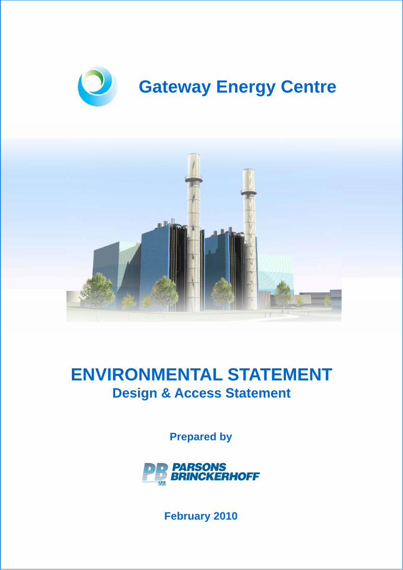
Gateway Energy Centre
ENVIRONMENTAL STATEMENTENVIRONMENTAL STATEMENTDesign & Access Statement
Prepared by
February 2010


Gateway Energy Centre – Design and Access Statement February 2010
CONTENTS Page
LIST OF ABBREVIATIONS
SECTION 1 1
DESIGN AND ACCESS STATEMENT 1 1.1 Introduction 3 1.2 The Reason for the Design and Access Statement 3
SECTION 2 7
THE PROJECT AND CONSULTATION 7 2.1 Overview 9 2.2 Physical Context 15 2.3 Social Context 15 2.4 Planning Policy Context 16
SECTION 3 17
DESIGN SOLUTION DEVELOPMENT 17 3.1 Site Layout and Massing 19 3.2 Architectural Design 22 3.3 Design Solution Development Stage 1 23 3.4 Design Solution Development Stage 2 28 3.5 Design Solution Development Stage 3 32 3.6 Sustainability 40 3.7 Conclusions 41
SECTION 4 43
DESIGN 43 4.1 Introduction 45 4.2 Amount 45 4.3 Use 46 4.4 Layout 46 4.5 Scale 49 4.6 Landscaping 53 4.7 Appearance 53 4.8 Lighting 53
SECTION 5 55
ACCESS 55 5.1 Introduction 57 5.2 Access during Construction 57 5.3 Access during Operation 58 5.4 Inclusive Access 59

Gateway Energy Centre – Design and Access Statement February 2010
LIST OF ABBREVIATIONS ACC Air Cooled Condenser CCGT Combined Cycle Gas Turbine CCR Carbon Capture Ready CABE Commission for Architecture and the Built Environment CECL Coryton Energy Centre Limited CEMP Construction Environmental Management Plan CHP Combined Heat and Power CO2 Carbon Dioxide DAS Design and Access Statement DECC Department of Energy and Climate Change DFO distillate fuel oil DP Dubai Ports EA Environment Agency EIA Environmental Impact Assessment ES Environmental Statement GECL Gateway Energy Centre Limited HGV Heavy Goods Vehicles HRSG heat recovery steam generators ILE Institution of Lighting Engineers km kilometre LCV lower calorific value LG London Gateway m metre m2 Metres squared MWe megawatts electric NOx Nitrogen Oxides NTaS National Grid National Transmission System OS Ordnance Survey PB Parsons Brinckerhoff Limited RSPB Royal Society for the Protection of Birds SUDS Sustainable Urban Drainage System TMP Transport Management Plan TTGDC Thurrock Thames Gateway Development Corporation


SECTION 1
DESIGN AND ACCESS STATEMENT


SECTION 1 DESIGN AND ACCESS STATEMENT
Gateway Energy Centre – Design and Access Statement February 2010 Page 3
1 DESIGN AND ACCESS STATEMENT
1.1 Introduction
1.1.1 This Design and Access Statement (DAS) has been prepared by Parsons Brinckerhoff Limited (PB) and Studio E Architects (Section 3 – Design Solution Development) on behalf of Gateway Energy Centre Limited (GECL) to support the Consent application for the proposed Gateway Energy Centre Combined Cycle Gas Turbine (CCGT) Power Plant to be known as Gateway Energy Centre or GEC.
1.1.2 The Consent application for GEC will comprise an application under Section 36 of the Electricity Act 1989 to the Department of Energy and Climate Change (DECC) to construct and operate a power station of greater than 50 MWe together with deemed planning permission under Section 90 of the Town and Country Planning Act 1990.
1.1.3 GEC will be located on land within the London Gateway Port / London Gateway Logistics and Business Park development, collectively called LG Development. The GEC site location is shown on Figure 1. The LG Development, promoted by DP World, is currently in the early stages of construction.
1.1.4 Once operational GEC will provide up to 900 megawatts electric (MWe) of electrical generation capacity. This will include the provision of up to 150 MWe to the LG Development, which is expected to meet its long term requirements.
1.2 The Reason for the Design and Access Statement
1.2.1 To ensure that the development of GEC has taken into consideration the potential environmental and social issues, GECL commissioned PB to provide technical and environmental support, including the undertaking of an Environmental Impact Assessment (EIA) and preparation of an Environmental Statement (ES), to support the Consent application for GEC.
1.2.2 This DAS has been prepared to accompany the Consent application for GEC, to demonstrate that GECL has fully considered the design and access issues associated with the development of GEC in accordance with Government Circular ‘Guidance on Changes to the Development Control System’.
1.2.3 The Circular advises that the DAS submitted should cover the following:
The Design Element
To show the process undertaken to explain the scheme in terms of it’s:
Amount – how much is to be built on the site;
Use – what the buildings and spaces will be used for;
Layout – how the buildings and public and private spaces will be arranged and how they interact with the site;
Scale – how large the buildings and spaces will be (their height, width and length);
Landscaping – how open spaces will be treated to enhance and protect the character of the area; and
Appearance – what the building and spaces will look like, for example, building materials and architectural details.
The Access Element
This should include an explanation of:

SECTION 1 DESIGN AND ACCESS STATEMENT
Gateway Energy Centre – Design and Access Statement February 2010 Page 4
Vehicular and Transport Links – why the access points and routes have been chosen, and how the site responds to road layout and public transport provision; and,
Inclusive Access – how everyone can get to and move through the place on equal terms regardless of age, disability, ethnicity or social grouping.
1.2.4 Based on the Circular referred to above, the Commission for Architecture and the Built Environment (CABE) has issued Guidance which states that the design process should explain how the physical characteristics of the development have been informed by assessment, involvement, evaluation and design.

NO
TES
TITL
E
CLI
EN
T/PR
OJE
CT
AN
D S
HO
ULD
ON
NO
AC
CO
UN
T B
E A
ME
ND
ED
BY
HA
ND
THIS
DR
AW
ING
WA
S P
RO
DU
CED
USI
NG
AU
TOC
AD


SECTION 2
THE PROJECT AND CONSULTATION


SECTION 2 THE PROJECT AND CONSULTATION
Gateway Energy Centre – Design and Access Statement February 2010 Page 9
2 THE PROJECT AND CONSULTATION
2.1 Overview
2.1.1 GEC will provide up to 900 MWe of power generation capacity. This will include the provision of up to 150 MWe to the LG Development, which is expected to meet its long-term electricity requirements.
2.1.2 The electricity generated at GEC will be dispatched to the High Voltage National Grid system. The electricity generated at GEC will most likely be dispatched to the High Voltage (HV) National Grid system via either a HV underground cable or a new overhead line, or a combination of both to a new substation to be constructed by National Grid most likely at Mucking Flats. A separate Consent application will be submitted for the HV cable / over head line connection in due course.
2.1.3 GEC will burn natural gas only. The natural gas used as fuel will most likely be taken from a new underground pipeline to be constructed from the National Grid National Transmission System (NTaS) Number 5 Feeder pipeline. A separate Consent application will be submitted for the gas pipeline in due course.
2.1.4 The natural gas will be burnt in the combustion chamber of each gas turbine from where the hot gases will expand through the gas turbine to generate electricity. The hot exhaust gases are then used in the heat recovery steam generator (HRSG) to generate steam, which in turn is used to generate electricity via the steam turbine equipment. The use of a combined gas and steam cycle increases the overall efficiency of the power plant.
2.1.5 GEC will be capable of generation in combined cycle mode with an overall electrical generation efficiency of approximately 55 per cent based on the lower calorific value (LCV) of the fuel. This efficiency rating does not take into account the potential for added fuel utilisation if it proves technically and economically feasible to supply waste heat.
2.1.6 The spent steam leaving the steam turbine equipment will pass to an Air Cooled Condenser (ACC) where it will be condensed. The resultant condensate will be returned to the HRSGs for reuse. The use of ACCs has the potential to eliminate environmental impacts associated with other cooling systems.
2.1.7 It is proposed that the gas turbines chosen for GEC will be equipped with standard proven pollution control technology, known as Dry Low NOx combustion, which will limit the production of NOx to the level required by the Environment Agency (EA).
2.1.8 Natural gas is a clean fuel and does not produce the particulate or sulphur emissions associated with burning coal. Consequently flue gas cleaning equipment is not required.
2.1.9 The flue gases will be discharged via two 75 m stacks. 2.1.10 As the detailed design of GEC will not be completed until a construction contract is in
place, it should be noted that the exact details of the siting, design, external appearance and dimensions of the buildings / structures, including colour, materials and surface finishes, cannot be identified and therefore a degree of flexibility of these dimensions is required. The exact dimensions will be agreed with Thurrock Thames Gateway Development Corporation (TTGDC) prior to the commencement of construction.
2.1.11 However, indicative details of site layouts and approximate sizes of buildings / structures have been used for modelling purposes and the EIA process, and are shown in Figure 2 (single-shaft layout) and Figure 3 (multi-shaft layout).


NO
TES
C
Cop
yrig
ht P
arso
ns B
rinck
erho
ff
TITL
E
CLI
EN
T/PR
OJE
CT


NO
TES
C
Cop
yrig
ht P
arso
ns B
rinck
erho
ff
TITL
E
CLI
EN
T/PR
OJE
CT

SECTION 2 THE PROJECT AND CONSULTATION
Gateway Energy Centre – Design and Access Statement February 2010 Page 15
2.1.12 GEC has a confirmed connection date for 2014. This would see construction commencing in around 2012, connection and commissioning commencing in around 2014, and full operation commencing in around 2015.
2.1.13 The GEC will be capable of operating throughout the year and will be designed to have an expected operational life in the order of 35 years.
2.2 Physical Context
2.2.1 Whilst the application site boundary for GEC incorporates areas to the north and west which may be used for temporary laydown during construction, the GEC site, is approximately 11.3 hectares (28.0 acres) in size.
2.2.2 The GEC site is situated on the north bank of the Thames Estuary and lies approximately 6 km east of the A13 Road. The A1014 dual carriageway (The Manorway) lies approximately 0.5 km to the north of the site and runs east to west to provide a link with the A13, which in turn links in with the M25 at Junction 30.
2.2.3 The nearest residential settlements are at Corringham and Fobbing which lie approximately 4 km to the west, Canvey Island which lies approximately 5 km to the east and Basildon approximately 7 km to the north.
2.2.4 The Ordnance Survey (OS) Grid Reference of the centre of the site is approximately 573209, 182165. The site location is shown in Figure 1.
2.2.5 To the east of the GEC site lies the existing 800 MWe CCGT Power Station owned and operated by Coryton Energy Company Limited (CECL), a subsidiary of the InterGen group, (700 m east) and the existing Coryton Oil Refinery (950 m east) owned and operated by Petroplus.
2.2.6 GEC will be located on land within the LG Development. The LG Development, promoted by DP World, is currently in the early stages of construction
2.2.7 The LG Development will involve the redevelopment of the former Shell Oil Refinery site at Shell Haven near Corringham and Stanford-le-Hope (Essex) together with associated transport connections, reclamation of part of the foreshore of the River Thames Estuary, and dredging of higher parts of the navigation channel within the Estuary to accommodate the passage of container vessels.
2.2.8 Once complete the LG Development is expected to become the most advanced deep-sea container Port in the UK, capable of handling approximately three and a half million cargo containers annually. The logistics and business park will serve the port and offer some nine million square feet of advanced business space for distribution and manufacturing companies.
2.3 Social Context
2.3.1 GECL and InterGen has endeavoured to maintain an appropriate level of discussion with stakeholders throughout the development process including in respect of design and access issues. Consultation has been undertaken, via a series of meetings and exchanges of correspondence, with a variety of groups, including:
Statutory Consultees such as DECC, the East of England Regional Assembly (EERA), the Environment Agency (EA), TTGDC, and Natural England (NE);
Non-Statutory Consultees such as Essex Wildlife Trust (EWT); and,
The local community.
2.3.2 This consultation will be ongoing throughout the development process to ensure design and access issues are addressed.
2.3.3 The feedback from this consultation has been used to shape the design of GEC, for example, it’s visual appearance.
2.3.4 A stakeholder and community consultation strategy has been developed to ensure that there is effective consultation as the Project advances through the various

SECTION 2 THE PROJECT AND CONSULTATION
Gateway Energy Centre – Design and Access Statement February 2010 Page 16
regulatory approval and consent procedures. This has included initial consultation on the design and access of GEC. The consultation undertaken is summarised in the Statement of Community Involvement which accompanies the Section 36 Consent application for GEC. Consultation will continue to feed into the detailed design process as the Project advances.
2.4 Planning Policy Context
2.4.1 The following planning policies are considered of particular relevance in the context of the DAS for GEC.
2.4.2 Policy ENV71 (Quality in the Built Environment) requires high quality design of all new development, coupled to “high standards of environmental performance”. New development should: provide buildings of an appropriate scale, founded on clear site analysis and urban design principles; make efficient use of land; address crime prevention, community safety and public health; promote resource efficiency and sustainable construction; reduce pollution, including emissions, noise and light; and, maximise physical, economic and community regeneration.
2.4.3 Thurrock Council recently approved the ‘Thurrock Core Strategy and Policies for Management of Development – Proposed Submission Draft Development Plan Document (DPD)’. This is to be submitted to the Planning Inspectorate and the Secretary of State.
2.4.4 Policy CSTP33 (Thurrock Design) of the draft DPD closely reflects the East of England Plan Policy ENV7 in seeking to deliver high quality design to achieve Thurrock’s environmental, economic and social objectives. It seeks to do this through supporting a robust design process, with the use of skilled designers, to provide:
Development with can demonstrate respect for the distinct characteristics of areas;
New designs of high architectural quality in appropriate locations;
The use of sustainable, renewable resources of energy and low-emissions technology; and
Developments which address the particular sensitivities and capacity of the places within which they occur, including the mitigation of any adverse impacts.
1 Taken from the East of England Plan

SECTION 3
DESIGN SOLUTION DEVELOPMENT


SECTION 3 DESIGN SOLUTION DEVELOPMENT
Gateway Energy Centre – Design and Access Statement February 2010 Page 19
3 DESIGN SOLUTION DEVELOPMENT
3.1 Site Layout and Massing
3.1.1 This Section has been prepared by Studio E Architects2 on behalf of GECL. This Section assumes that GEC is built as per Figure 3 (the multi-shaft layout) and that is it located within the built LG Development.
3.1.2 The locations of the principal buildings making up the proposed GEC are generally defined by the key process flow requirements of producing electricity. The proposed layouts generate a dynamic form and massing for the development which responds positively to the site’s context. Whilst the length and height of all the buildings and structures are defined by process requirements, the proposed development offers a dramatic visual improvement to those structures, which currently border the eastern boundary of the site, particularly when viewed from within the proposed LG Logistics and Business Park. They also conform in principle to the indicative LG Design Guidelines which are informing the design of the LG Development.
3.1.3 The layout of GEC has been developed in consideration of the key elements of the LG Logistics and Business Park, which is yet to be built, as indicated on the LG Conceptual Masterplan to reflect current LG Logistics and Business Park proposals. However, it should be noted that the existing Planning Permission for the LG Logistics and Business Park is outline, with matters of layout, scale, appearance and landscaping reserved for future consideration. Therefore, the LG Site Masterplan is conceptual and subject to variation with the submission and approval of future reserved matters applications.
3.1.4 As shown on the indicative site layout in Figure 3 (the multi-shaft layout), the principle building of GEC is located centrally on the site and is the physical and process heart of the facility. Its overall size and scale allows it to visually screen the outdoor switch yards and ACC from the LG Development, as indicated within the LG Logistics and Business Park Conceptual Masterplan. Extending from the western face of this principle building are two HRSG and stacks, which form the centrepiece of the development. These structures also visually terminate at the eastern end of the east / west road within the LG Development, as indicated within the LG Logistics and Business Park Conceptual Masterplan. In considering their architectural treatment these structures offer an exciting opportunity to develop a dramatic response to the facility’s principle frontages to the site’s northern and western boundaries as indicated within the LG Logistics and Business Park Conceptual Masterplan. In further response to this western frontage, two of the development’s lower height buildings are located along this boundary and visually reduce the scale of the overall facility along this section of the north / south access road and visually screen a range of other independent freestanding structures and outdoor process equipment within the site from the LG Development users.
3.1.5 The site’s southern river frontage will be screened for the most part by the LG Port development. However, the site layout and massing also present a unified visual aesthetic to views from the River Thames. In addition, it offers the opportunity to develop an architectural treatment, which responds positively to it’s riverside setting and further enhance the visual cohesion of the development.
3.1.6 Whilst it is clear that site constraints and process flows have been key drivers in the disposition and massing of the proposed GEC, the resulting overall site layout and massing also offer:
A development which is dynamic in form; A positive response to the context of the site and its surroundings;
2 http://www.studioe.co.uk/

SECTION 3 DESIGN SOLUTION DEVELOPMENT
Gateway Energy Centre – Design and Access Statement February 2010 Page 20
A dramatic visual improvement to that which currently forms the eastern backdrop to the site; and
A range of exciting architectural design solutions.
3.1.7 The site massing drawings shown in Insert 3.1 illustrate how the current proposal offers a unified development of the site and a potentially dramatic interface with the LG Development.

SECTION 3 DESIGN SOLUTION DEVELOPMENT
Gateway Energy Centre – Design and Access Statement February 2010 Page 21
INSERT 3.1 – GATEWAY ENERGY CENTRE SITE MASSING DRAWINGS3
3 The building heights shown in the LG Logistics Park are shown as three uniform heights in the massing drawings, however in practice these may be a mixture of heights when the LG Logistics Park is fully developed.

SECTION 3 DESIGN SOLUTION DEVELOPMENT
Gateway Energy Centre – Design and Access Statement February 2010 Page 22
3.2 Architectural Design
3.2.1 Given that the proposed GEC indicative layout and the principle massing of the GEC Development respond positively to the site’s context and do not restrict the range of alternative architectural approaches available, a series of design studies have been developed to consider how the proposed GEC’s architectural design might develop from this basis.
3.2.2 In determining which design approaches might be appropriate for the development, an early decision to reject those options which stray beyond those required to efficiently house the process equipment has been taken.
3.2.3 For example, the option to develop a more dynamic architectural roof form has been considered but rejected in favour of a roof form that follows the technology equipment contained within. This approach offers several benefits:
The overall height of the buildings is maintained as low as possible thereby minimising the visual impact of the development and associated structures from key distant views;
The flat roof form is more in keeping with the aesthetic of the predominantly ‘flat’ roof buildings which will make up the LG Develoment;
A consistent flat roof form reflects the linearity of the landscape within which it sits;
It ensures that the overall building height does not compromise the process efficiency of adjacent structures and equipment making up the GEC development such that a corresponding potential increase in stack height is not required; and
It is a more efficient and sustainable approach.
3.2.4 Similarly, the use of a ‘sculpted’ design approach, which would lead to ‘moulding’ the wall cladding of the buildings beyond that required for enclosing the process equipment has not been selected. In the context of the GEC development this offers several benefits:
The overall scale of the development is minimised; The physical footprint of the development is minimised; and Taking the envelope of the buildings beyond that required to efficiently house
the process would negatively impact upon the overall site layout (raising issues related to health and safety, access, egress and maintainability) and would lead to a sub-optimal design solution for GEC.
3.2.5 It is, therefore, concluded that the development of a range of architectural options based upon a ‘form follows function’ design approach is the most appropriate for the proposed GEC development.
3.2.6 What follows is a summary of the options developed and reviewed for GEC in order to suggest how the design could evolve. In developing the architectural studies a range of key objectives were identified as follows:
Cohesive Design Statement; Develop ‘a family of buildings’
Scale; Consider the relationship between buildings / structures on and off the site
Proximity; Recognise relationship and impact on the adjoining LG Development
Considerate of LG Design; Incorporate LG Design Guidelines where appropriate

SECTION 3 DESIGN SOLUTION DEVELOPMENT
Gateway Energy Centre – Design and Access Statement February 2010 Page 23
Materials and Textures; and Explore opportunities and consider contrast
Contemporary Aesthetic. To reflect the new age, hi-tech energy facility
3.2.7 As part of the design brief, each Design Solution was developed and reviewed against the above objectives, leading to the conclusion that each of the following Design Concepts embraces and successfully integrates these criteria.
3.3 Design Solution Development Stage 1
3.3.1 The approach in Design Solution Development Stage 1 was to celebrate the massing of the development and horizontally stratify the buildings by applying visual ‘wraps’ to the principal buildings. The ‘wraps’, with darker colour bands at the bottom and lighter colour bands at the top of key buildings, is in keeping with the LG Design Guidelines for development within the LG Development.
3.3.2 This balances the vertical scale of the two stacks but also further emphasises the horizontal aspect of the main building and links it proportionally to the ACC enclosure.
3.3.3 In the most extreme case, a cladding concept was developed as differentiated ‘ribbons’ wrapped around the buildings. However, whilst this concept was considered visually dynamic, this ‘sculpted’ approach, shown in Insert 3.2, was rejected for the reasons detailed above in the Sub-Section ‘Architectural Design.’

SECTION 3 DESIGN SOLUTION DEVELOPMENT
Gateway Energy Centre – Design and Access Statement February 2010 Page 24
INSERT 3.2 – REJECTED RIBBONS CONCEPT
(a) Massing Model
(b) Ribbon Cladding
(c) Stratified Ribbons

SECTION 3 DESIGN SOLUTION DEVELOPMENT
Gateway Energy Centre – Design and Access Statement February 2010 Page 25
3.3.4 After identifying that the preferred approach was to apply visual wraps to horizontally stratify the buildings in the form of varying colours and textures, it was decided to test this approach using three alternative design options to consider how the building form might be developed.
3.3.5 Each approach offered the opportunity to add significant visual interest to the site’s key elevations and has helped to reduce the overall massing of the main structures. In addition, this approach allowed each option to be tested against two keys views from the LG Development. These were: the southernmost east / west road; and, easternmost north / south road as indicated within the LG Logistics and Business Park Conceptual Masterplan. The building form options and their associated views are shown in Insert 3.3.

SECTION 3 DESIGN SOLUTION DEVELOPMENT
Gateway Energy Centre – Design and Access Statement February 2010 Page 26
INSERT 3.3 – BUILDING FORM OPTIONS AND ASSOCIATED VIEWS
Option 01 – ‘Planar’
Option 02 – ‘Cubist’
Option 03 – ‘Volumetric’
SECTION 3 DESIGN SOLUTION DEVELOPMENT
Gateway Energy Centre – Design and Access Statement February 2010 Page 27
3.3.6 The three Options shown in Insert 3.3 are discussed further here.
Option 01 – Planar
3.3.7 The ‘Planar’ Option 01 treats the development as a refined architectural form with the external envelope being emphasised in a series of wall planes which rise to varying heights to visually shield all of the process equipment including that which is roof mounted.
3.3.8 This approach is particularly dynamic where the wall plates clad the sides of each of the HRSGs and stop to frame the stacks. This leaves the space between the side walls open to offer views of the HRSG casing contained within. The coloured bands which have been applied to the walls are appropriately scaled to reflect the massing of the overall facility. The overall height has been visually tempered by employing lighter cladding at the top of the key buildings.
Option 02 – Cubist
3.3.9 The ‘Cubist’ Option 2 is in many ways similar to that developed for the ‘Planar’ Option 01, but differs in that it maintains a more consistent height between the HRSG and turbine hall to generate a more unified simpler cubist form for the overall development.
3.3.10 This approach continues the horizontal bands of colour around the HRSGs but as it is roofless (to promote ease of maintenance) exposes the top, pulling the mass of the building closer to ground.
Option 03 – Volumetric
3.3.11 The approach behind the ‘Volumetric’ Option 03 was to blend the two approaches together but allow the external envelope to partly enclose the base of the stacks with the result that the building volume is visually increased at lower level.
3.3.12 On review it was considered that this approach was inappropriate due to the increase in scale of the building and the visual fracturing of the principle elevation when viewed from the southernmost east / west road in the LG Development as indicated within the LG Logistics and Business Park Conceptual Masterplan.
Interim Conclusion
3.3.13 The interim conclusion was that further studies would be required to explore the ‘Planar’ Option 01 and ‘Cubist’ Option 02 approaches, but that the ‘Volumetric’ Option 03 would not be pursued further for the reasons stated above.
TTGDC Workshop Review 4 February 2010
3.3.14 As part of the Design Solution Development Stage 1 process, a meeting with TTGDC was held on 4 February 2010. The purpose of this meeting was to present the progress of this stage of the architectural design development, including an analysis of the existing site and its context, and the presentation of the range of design concept options that had been thus far considered. It was agreed that the decision to develop a refined approach to the design rather than to develop a sculpted volumetric form for the building was an appropriate design approach.
3.3.15 Whilst there was generally a positive response to the presentation and the architectural design approaches being developed, TTGDC raised a number of issues which would need to be considered as part of the ongoing design development work, namely:
It was suggested that the opportunity to centralise the twin stacks on the centreline of southernmost east / west road within the LG Development should be explored further;

SECTION 3 DESIGN SOLUTION DEVELOPMENT
Gateway Energy Centre – Design and Access Statement February 2010 Page 28
Consideration should be given to reviewing opportunities to reveal parts of the process equipment as part of the overall design approach (for example the heat recovery steam generator behind the stacks); and
External lighting of the development should be explored and opportunities for the internal operational lighting to highlight parts of the facility at night should also be included within this review.
3.3.16 TTGDC agreed with the team’s conclusion that the ‘Volumetric’ Option 03 approach be rejected in favour of developing further studies to explore the ‘Planar’ Option 01 and ‘Cubist’ Option 02 approaches. The scope of these studies would include both the building form and the potential colour palettes.
3.3.17 The issues highlighted by TTGDC noted above have informed Stage 2 of design development.
3.4 Design Solution Development Stage 2 3.4.1 At the start of this stage of design, the matters raised during the Design Solution
Development Stage 1 process were considered with LG. On balance it was considered that centralising the stacks on the road was not optimal as many of the building forms in the LG Development are not symmetrical and there are many examples where buildings are offset to each other to create visual interest within the master plan. Furthermore, a symmetrical approach with the centralised stacks and east / west road, as indicated within the LG Logistics and Business Park Conceptual Masterplan, may appear to seem too artificial.
3.4.2 Given this feedback Design Solution Development Stage 2 designs were developed with off centre stacks to the centre line of the southernmost east / west road on the LG Development as indicated within the LG Logistics and Business Park Conceptual Masterplan.
3.4.3 Accordingly, Stage 2 of the Design Solution Development explored opportunities to develop the architectural form against the ‘‘Planar’ Option 01 and ‘Cubist’ Option 02 design concepts. Option 01A – ‘Planar’ Approach
3.4.4 The design option illustrated in Insert 3.4 shows how a ‘Planar’ approach to treating the architectural envelope might be developed. It builds on the ‘Planar’ Option 01 design covered in the Design Solution Development Stage 1 and the relationship between the side faces of the HRSGs and their interface with the turbine hall building.
3.4.5 In this case these plates visually slice in to and engage with the volume of the turbine hall, and are left open behind the stack revealing the process equipment contained within. Option 01B – ‘Planar’ Approach
3.4.6 This is a variant on Option 01A in that it visually breaks the side walls of the HRSG units away from the turbine hall building leaving a gap between which can either reveal the equipment within or be treated in contrasting cladding and colour to emphasise the break. This also allows for more flexibility in considering the colour and texture of each which is explored later in this DAS. Option 02C – ‘Cubist’ Approach
3.4.7 In contrast to the ‘Planar’ Option 01 approach the ‘Cubist’ Option 02 approach tests the impact that full enclosure of the HRSG and turbine halls might have upon the overall appearance of the development.
3.4.8 This option shown in Insert 3.4 considers this approach and how proportionally the mass of the turbine hall and the HRSG might relate.

SECTION 3 DESIGN SOLUTION DEVELOPMENT
Gateway Energy Centre – Design and Access Statement February 2010 Page 29
Option 02D – ‘Cubist’ Approach
This option attempts to break down the mass of the boiler hall evident in Option 02C by opening up the sides of the enclosure to expose the process equipment.

SECTION 3 DESIGN SOLUTION DEVELOPMENT
Gateway Energy Centre – Design and Access Statement February 2010 Page 30
INSERT 3.4 – DESIGN SOLUTION DEVELOPMENT STAGE 2
Option 01A – Planar Approach
Option 01B – Planar Approach

SECTION 3 DESIGN SOLUTION DEVELOPMENT
Gateway Energy Centre – Design and Access Statement February 2010 Page 31
Option 02C – Cubist Approach
Option 02D – Cubist Approach

SECTION 3 DESIGN SOLUTION DEVELOPMENT
Gateway Energy Centre – Design and Access Statement February 2010
Interim Conclusions
3.4.9 After a review of Options 01A, 01B, 02C and 02D (including an assessment of such criteria as: massing; scale; proportion; and, materiality) it was concluded that Option 01B ‘Planar Approach,’ with the break between the HRSG and turbine hall, was the preferred Option.
3.4.10 Option 01B ‘Planar Approach’ responds positively to the TTGDC request to review where the building might offer opportunity to expose the internal process equipment as part of the visual palette of the design by adding a break in the cladding between turbine hall and HRSG interface and by removing the west facing end walls of the HRSGs behind the stacks offering additional visual interest from the frontage facing LG Development. This approach also provides the opportunity to develop the colour and texture palette of the HRSG side wall cladding and turbine hall cladding independently of each other.
3.4.11 Therefore, it is this Option which has been selected to develop further in the Stage 3 Design Solution Development. During Stage 3, alternative colour studies for GEC are discussed.
3.5 Design Solution Development Stage 3
3.5.1 The following range of images and views, shown in Insert 3.5 to Insert 3.7, test a number of colour options when applied to the ‘Planar’ Option 01B design with the break between the turbine hall and HRSGs.

SECTION 3 DESIGN SOLUTION DEVELOPMENT
Gateway Energy Centre – Design and Access Statement February 2010 Page 33
INSERT 3.5 – COLOUR SCHEME 01

SECTION 3 DESIGN SOLUTION DEVELOPMENT
Gateway Energy Centre – Design and Access Statement February 2010 Page 34

SECTION 3 DESIGN SOLUTION DEVELOPMENT
Gateway Energy Centre – Design and Access Statement February 2010 Page 35
INSERT 3.6 – COLOUR SCHEME 02

SECTION 3 DESIGN SOLUTION DEVELOPMENT
Gateway Energy Centre – Design and Access Statement February 2010 Page 36

SECTION 3 DESIGN SOLUTION DEVELOPMENT
Gateway Energy Centre – Design and Access Statement February 2010 Page 37
INSERT 3.7 – COLOUR SCHEME 03

SECTION 3 DESIGN SOLUTION DEVELOPMENT
Gateway Energy Centre – Design and Access Statement February 2010 Page 38

SECTION 3 DESIGN SOLUTION DEVELOPMENT
Gateway Energy Centre – Design and Access Statement February 2010 Page 39
Colour Studies - Overall Strategy
3.5.2 In all three Options, colour is carefully used to focus attention to particular elements of the scheme. The two HRSG units adjacent the turbine hall provide the main frontage to the scheme as viewed from the main southern east / west road on the LG Development as indicated within the LG Logistics and Business Park Conceptual Masterplan. Previous studies in the earlier design development phases focused on these units, so it is important that the colour strategy compliments the decisions made earlier in the process. Therefore it proposed that single colour, vertically orientated cladding would best highlight the boilers.
3.5.3 The administration building which marks the entrance to the site is also an element that can be distinguished in the scheme. Linking this building visually to the main turbine hall gives the impression of a ‘Gatehouse’ and further highlights the function of the building as a control point to the site.
3.5.4 In general all of the colour options create a composition that helps the scheme link together as a whole.
Colour Scheme 01
3.5.5 Colour Scheme 01 uses the blue coloured cladding to emphasize the HRSG units, the administration building and the ACC. The elements are highlighted by the colour of the main turbine hall which creates a subtle, less obvious backdrop to the units by using a horizontal tonal banding of three tones of grey / silver. The cladding scheme creates a gradient which lightens towards the sky. The banding of colour complements LG’s potential strategy to treat the other units within the park.
Colour Scheme 02
3.5.6 Similar to Colour Scheme 01, Colour Scheme 02 uses blue to highlight the HRSG units, the administration building and the ACC, but treats the turbine hall differently. The turbine hall is clad at low level with a band of blue vertically profiled material. The top two thirds of the turbine hall are then clad with a single grey / silver coloured horizontally profiled material to give the impression that it sits on a blue plinth. This approach grounds the mass of the turbine hall by reducing the impression of its height.
Colour Scheme 03
3.5.7 In Colour Scheme 03 it is the HRSG units alone which are highlighted by applying a contrasting colour (orange) to the flanking walls. This separates the volume of the HRSG units completely from the rest of the scheme. This Scheme adopts a similar strategy to Colour Scheme 01 in its treatment of the turbine hall, except that it uses a gradient of blue tones to band the mass. The administration building and the ACC also follow suit in this banding; with the datums for colour change dictated by those on the turbine hall. The ACC is therefore in the lightest shade of the blue and the administration building has a stripe of the mid tone blue added to the top of its four façades.
Design Solution Development Stage 3 Summary
3.5.8 After reviewing the three Colour Schemes, it is proposed that two out the three Schemes offered positive contributions towards the design. The low level blue band in Colour Scheme 02, works well in uniting the two HRSG units with the overall architecture of the main turbine hall building. However, the blue gradient banding in Colour Scheme 03 which runs throughout works better in helping the scheme read well as a whole. The lighter shade of blue for the high level ACC also reduces the impact within the photomontage. The orange treatment to the HRSG units in this Colour Scheme 03, works well to contrast with the blue, but fails to join the HRSG units architecturally to the turbine hall building of which they are a part. For this reason Colour Scheme 01 was also disregarded.

SECTION 3 DESIGN SOLUTION DEVELOPMENT
Gateway Energy Centre – Design and Access Statement February 2010 Page 40
3.5.9 On this basis it is thought that a fourth Colour Scheme would be feasible, this being a hybrid of Colour Scheme 02 and 03, in which the blue tonal banding of Colour Scheme 03 is adopted but the walls to the HRSG units are clad in a single blue tone to match the lower band of the turbine hall. This creates the same benefits enjoyed by Colour Scheme 02 which unite the HRSG units to the turbine hall and also lets the scheme read as a whole through the tonal banding.
INSERT 3.7 – COLOUR SCHEME 04 – HYBRID OPTION
3.5.10 This hybrid Colour Scheme 04, which is based on Colour Schemes 02 and 03, was then taken forward for visual impact assessment based on a series of photomontages.
3.6 Sustainability
3.6.1 There is waste heat potential for steam for refrigeration stores and a district heating scheme on the LG Development. At present, this is subject to further feasibility studies and is dependent on the type of tenants that will be eventually occupy the LG Development.
3.6.2 Other on-site uses of waste heat may be feasible and may include utilisation of waste heat to supply central heating and hot water to administrative areas including offices, mess rooms and wash rooms. Both these opportunities will be investigated further, subject to granting of Section 36 Consent and as detailed designs progress.
3.6.3 In addition, the following features serve to emphasise the sustainability credentials of the Project:
The re-use of previously developed land;

SECTION 3 DESIGN SOLUTION DEVELOPMENT
Gateway Energy Centre – Design and Access Statement February 2010 Page 41
Increased employment opportunities for local people, helping to promote social inclusion and well-being;
Day lighting and natural ventilation of the various occupied buildings will be maximised where appropriate (administration office only as remaining buildings house process equipment only);
The administration facility may include a ‘brown’ roof which is one of the on-site ecological mitigation and enhancement measures for the development;
The implementation of rainwater harvesting, where feasible, will reduce the demand for mains water supply and will be considered further;
The environmental performance of the materials to be specified for the construction of the facility will be taken into account during procurement activities and will be selected as far as possible to achieve a BRE Green Guide ‘A’ Rating where appropriate (administration office only as remaining buildings house process equipment only);
Construction contracts will encourage the re-use and recycling of materials where practicable. A Construction Environmental Management Plan (CEMP) will include sustainability and environmental issues and be linked to a design and construction sustainability register to ensure that the Project delivers sustainability objectives; and
Site waste management plans will be required from the contractors to demonstrate that waste is being minimised and sustainable practices are being followed in construction.
3.7 Conclusions
3.7.1 Stage 1 of the Design Solution Development work for GEC included consultation with LG and the TTGDC Design Officer to highlight the way in which the design options could be developed.
3.7.2 The outcome of these discussions steered Stage 2 of the Design Solution Development work such that the design of GEC has been evolved to incorporate the matters highlighted during the process, clearly demonstrating:
That the site layout design and the massing of GEC is appropriate for its site and its context;
That a range of exciting and dynamic architectural design solutions can be developed from the these; and
That a range of alternative colour palettes are available to add further visual interest and break down the massing of the facility whilst also celebrating its scale and function.
3.7.3 In parallel to the Colour Studies being developed, a review of the potential materials that might complement the development of the architectural design and colour options is being undertaken. In further development of the architectural concepts presented within this document, GECL will seek to explore materials which satisfy the following characteristics:
Offer a high visual quality which is in keeping with the developed design concepts;
Offer a range of textures and colours to enable contrast between different building / structures to be developed as appropriate;
Be low maintenance and/or naturally weathering; and Be environmentally responsible as appropriate.
3.7.4 It should be noted that, at this stage no single architectural treatment is being proposed. Rather a range of opportunities that could be pursued and developed in

SECTION 3 DESIGN SOLUTION DEVELOPMENT
Gateway Energy Centre – Design and Access Statement February 2010 Page 42
further detail are discussed, should Section 36 Consent be granted. The details of materials are not included as part of this submission, but will be developed alongside the architectural design and the requirements in a planning condition to submit all design details for approval to TTGDC.

SECTION 4
DESIGN


SECTION 4 DESIGN
Gateway Energy Centre – Design and Access Statement February 2010 Page 45
4 DESIGN
4.1 Introduction
4.1.1 Further to the discussion provided in Section 3 (Design Solution Development), this Section describes the process undertaken during the design of the GEC. It also highlights that the design process for the GEC was carried out in a structured and rigorous manner.
4.1.2 The design of the GEC reflects the overall objective which is to provide an efficient, controlled, working environment within which the high efficiency CCGT technology will be operated by experienced personnel.
4.1.3 A full EIA has been undertaken for the GEC and this has been used to inform the design and layout of the development. The EIA can be broken down in to three basic process components:
1. Collection of baseline data against which the impacts are considered;
2. Assessment of the impacts; and
3. Development of mitigation measures and monitoring programmes to minimise any identified impacts, and ensure that the project is environmentally and socially acceptable.
4.1.4 These components are discussed in detail in the ES, which also includes discussion on how the EIA process has shaped the design and layout of GEC.
4.1.5 Additionally, the site layout and composition has been refined during the EIA process to incorporate the views of the Statutory and Non-Statutory Consultees wherever possible.
4.1.6 Throughout the design of the GEC, GECL has sought to minimise the impact of the Project. In particular, additional care has been taken in minimising impacts of noise, air, water quality and visual appearance, which are typically the main environmental impacts associated with power plants. This has been achieved through listening to the concerns of interested parties including Statutory and Non-Statutory Consultees, as well as members of the general public.
4.1.7 In addition, careful consideration has been given to all relevant Planning Policies in the refinement of the plant design.
4.2 Amount
4.2.1 The GEC site is 11.3 ha in total. The land within the proposed GEC site will be used as follows:
6.6 ha of land lying centrally within the GEC site. The main buildings and structures of the GEC will be constructed within this area; and
4.7 ha of land lying in the north of the GEC site. This area has been set aside for the installation of Carbon Capture equipment should this be required in the future.
4.2.2 The layout of the GEC showing the above land areas can be found on illustrative layouts provided Figure 2 (single-shaft layout) and Figure 3 (multi-shaft layout).
4.2.3 The amount of development is appropriate because this is the area required for all the plant associated with GEC. Table 1 (later in this Section) details the main equipment boundary sizes.

SECTION 4 DESIGN
Gateway Energy Centre – Design and Access Statement February 2010 Page 46
4.3 Use
4.3.1 The proposed use of the GEC is power generation and the supply of waste heat subject to technical and commercial feasibility.
4.3.2 GEC will provide up to 900 MWe of power generation capacity at site rated conditions and will burn natural gas only. Up to 150 MWe of power will be provided to the LG Development.
4.3.3 The Consent application follows an in-depth site selection process and a number of feasibility studies to establish that the site is a suitable location for a gas-fired CCGT power station.
4.3.4 The reasons for selection of the proposed site are discussed in depth within Section 6 of the ES. In summary, they include:
The close proximity of the national electricity transmission system; The close proximity of the national gas transmission system; Availability of industrial sites with sufficient land area; Economic benefits of proximity to the national electricity and gas networks; Compatibility with planning polices and local development plan; Environmental considerations (such as conservation designations and the
presence of protected species); Likely suitability for carbon capture equipment if required in the future; and Opportunities to link beneficially with local industry.
4.3.5 In addition, the location of the existing InterGen Power Generation is an important consideration in the site selection process. Constructing a new plant near to an existing power station is standard industry practice as it allows power generators to take advantage of economies of scale and utilise existing infrastructure wherever possible.
4.3.6 The Project is supported by National Energy Policy. The Planning Statement submitted to support the Section 36 Consent application demonstrates that the Project is consistent with all relevant planning policies.
4.4 Layout
4.4.1 The main items of plant listed below, which comprise GEC, are described in Section 4 of the ES. These are also shown in the illustrative site layouts shown in Figure 2 (single-shaft layout) and Figure 3 (multi-shaft layout).
4.4.2 As the detailed design of the GEC will not be completed before a construction contract is in place, final design details will be submitted to LG and TTGDC for approval before the main development of GEC can commence. All aspects of the proposed GEC have therefore been considered on a “worst case basis”. For example, the stack heights for purposes of visual assessment have been assumed to be 75 m.
4.4.3 The main process plant to be situated on the 11.3 ha site, will include:
2 x Gas Turbines;
2 x HRSGs;
Space for side walls on adjacent sides of the HRSGs to mitigate noise;
Full penetration HRSG tube to helder welds;
1 or more Steam Turbines;
2 Stacks;

SECTION 4 DESIGN
Gateway Energy Centre – Design and Access Statement February 2010 Page 47
Air Cooled Condensers (ACC) and Ancillary Cooling;
2 or more Transformers;
Space for a stand-alone Control Room (if not combined with the Administration Building);
Gas Reception Facility;
Space for water bath heaters to pre-heat the incoming natural gas if required;
Water Treatment Plant, including space for a sufficiently over-sized Water Treatment Plant in case of a significant open loop CHP scheme (no return water);
3 Water Tanks (for demineralised water; raw water; and, fire water);
Space for Water Tanks for a significant CHP regime;
Space for 3 Auxiliary Boilers in the case of a requirement for significant CHP regime / secure steam supply;
Full steam turbine bypass;
Vacuum raising equipment;
Space for 2 x 100 per cent compressors;
Space for duct firing;
Space for maintenance lay down;
Space for Carbon Capture equipment to the north of the CCGT site;
Space for exhaust flue ducting from the CCGT to the Carbon Capture equipment area, and all associated Carbon Capture interconnections with the CCGT; and
Space for easements for gas, grid, carbon dioxide (CO2), steam and minor services.
4.4.4 The layout and design of the proposed GEC gives consideration to environmental impacts, in particular: noise; emissions; and, visual appearance. Many of the same technologies used within the existing CECL Power Station will be employed and the power stations will be of a similar size. All equipment used in the GEC development will be modern and proven in the power generation industry. A full description of the Project is included in Section 4 of the ES, which includes detailed discussion of the layout, and all on site processes.
4.4.5 The design of the proposed GEC will aim to incorporate a number of sustainable design and specification measures. This may include: low energy building design; rainwater harvesting; and Sustainable Urban Drainage Systems (SUDS) Pond(s).
4.4.6 The layout of the proposed GEC will take the following factors into consideration:
The presence and form of the existing CECL Power Station, LG Development and wider Industrial Complex, including potential for interconnections and shared services, including; The orientation of the LG Development buildings with respect to airflow; Consideration of the vistas from the main east / west road in the LG
Development (as indicated within the LG Logistics and Business Park Conceptual Masterplan or successor documents or similar);
Potential to build up the landscaping by the main entrance to the GEC site;

SECTION 4 DESIGN
Gateway Energy Centre – Design and Access Statement February 2010 Page 48
The availability of land; Access arrangements; Technical requirements; Reduction of environmental impacts, including:
Noise; Emissions; Visual impacts; Water use and protection of the water environment;
Opportunities for ecological enhancement; Government Guidance and Regulatory Requirements; Requirement for Carbon Capture Readiness (CCR); Infrastructure connections (i.e. gas pipeline and overhead transmission line); Implementation of a CHP scheme or schemes; Design feedback from the EIA and stakeholder consultation process; and Financial considerations.
4.4.7 The main gas turbines and steam turbine(s) will be located in the central part of the GEC site and enclosed within the main power building. Whilst the HRSGs will be situated outwith the turbine hall, they will be enclosed within side walls to provide noise attenuation, as appropriate.
4.4.8 The stacks for the flue gases will be situated close to each gas turbine unit and will be 75 m in height.
4.4.9 The ACC will be located close to the steam turbines to allow for an appropriate air flow to the condenser intakes.
4.4.10 Export of electricity from the GEC will be achieved via switch yard equipment most likely to be located in the north eastern area of the proposed GEC site.
4.4.11 New on-site roads and paved areas will be provided as required. The primary site access for staff and visitors during operation of GEC will be via the security controlled northern entrance to the GEC site. Access is discussed further in Section 5 of this DAS.
4.4.12 Lubricating oils will be stored on site within bunded areas large enough to contain 110 per cent of the contents of each tank. This is in line with the Oil Storage Regulations 2001. Used lubricating oils will also be stored on site for re-use or will be disposed of off-site by an approved and licensed contractor. Storage facilities will also be provided for the small quantities of chemicals used in boiler water dosing. All such chemicals will be retained in suitable containment areas. A demineralised water storage tank will be provided on the GEC site. The demineralised water for this tank will be supplied from a demineralisation plant. Miscellaneous materials such as oils, greases, cleaning substances and materials, laboratory chemicals etc, will be stored in suitable storage conditions or containers on site.
4.4.13 The layout of the GEC site has been designed with its servicing in mind and sufficient space has been provided for a large refuse vehicle to enter and leave the site in a forward gear. Visits of service vehicles such as these are expected to be very infrequent and will access the GEC site via the security controlled northern entrance to the GEC site by prior arrangement.
4.4.14 A steel palisade fence will be constructed around the GEC site for security reasons, and the GEC site will be fitted with closed circuit television (CCTV).

SECTION 4 DESIGN
Gateway Energy Centre – Design and Access Statement February 2010 Page 49
4.4.15 Included within the application boundary is an area of land to be used temporarily for car parking and storage of materials and equipment during the construction phase of GEC.
4.4.16 In addition, there is an area of land to be set aside for the installation of the carbon capture equipment if required in the future.
4.5 Scale
4.5.1 The estimated main structure / plant items areas and heights for the GEC are shown in Table 1. These areas are also shown in Figure 4. The exact dimensions cannot be identified until the detailed design process is completed and a contractor is selected.
TABLE 1 – ESTIMATED MAIN STRUCTURE / PLANT ITEM AREAS/HEIGHTS
Structure / Plant Item Height (Up To)
(m)
Area (m2)
Gas Receiving Facility (Orange Area) Gas Receiving Facility
14 6 080
Water Storage Tanks (Brown Area) Demineralised Water Storage Tank Raw / Firewater Tank Water Treatment Plant
23 11 600
Administration Block (Pink Area) Warehouse, Maintenance, Admin and Control
Building Car Parking
17 6 870
Main CCGT Plant (Blue Area) Gas Turbine Area Heat Recovery Steam Generator Steam Turbine Area Transformers Air Cooled Condensers
42 41 600
Stacks (Black stripped Area within the Blue Area) 75 Within Main CCGT Plant
CCS Area (Green Area) - 47 100
4.5.2 The building / plant give a site cover ratio of about 50 per cent. The remaining hard areas comprise mainly roads / footpaths / surface yards and car parking.
4.5.3 Again it should be noted that full details of the Project are included in Section 4 of the ES.


NO
TES
C
Cop
yrig
ht P
arso
ns B
rinck
erho
ff
TITL
E
CLI
EN
T/PR
OJE
CT


SECTION 4 DESIGN
Gateway Energy Centre – Design and Access Statement February 2010 Page 53
4.6 Landscaping
4.6.1 GEC will be located on land within the LG Development. Due to its location, the type of landscaping on the GEC site will conform visually with that of its surroundings.
4.7 Appearance
4.7.1 GEC has been designed to avoid, reduce and remediate impacts on the visual resource as follows (using the indicative LG Logistics and Business Park Conceptual Masterplan:
The GEC site location situated on land within the south east corner of the LG Development to minimise visual impact;
The Administration Building; Warehouses and Water Treatment Plant are located on the western GEC site boundary. Any buildings on the western site boundary will form a more prominent view from the main southern most east / west road in the LG Development. As such, the shape and form of these buildings are more likely to immediately blend with the appearance of the LG Development and are therefore located in this area; and
The orientations of the centre lines of the key buildings are in the same direction as those on the LG Site Masterplan to achieve a level of visual consistency.
4.7.2 The external surfaces of the buildings will be designed such that there will be minimal material deterioration in the appearance of GEC over its 35 year operational lifetime. In addition, it is likely that a limited combination of materials will be used in the construction of the external structures to give a cohesive appearance to GEC.
4.8 Lighting
4.8.1 Subject to feedback from LG and TTGDC, it is proposed that the external lighting for GEC will be designed in compliance with Guidance published by the Institution of Lighting Engineers (ILE)4. The objectives of this Guidance are to limit:
The average upward light ratio of luminaries to restrict sky glow; The illuminance at the windows of nearby sensitive properties; The intensity of each light source in potentially obtrusive directions; and The average illuminance of a building, where it is floodlit.
4.8.2 Lighting will be directed to where it is needed and measures will be taken to avoid light spillage. This will be achieved by the design of the luminaire and by using accessories such as hoods, cowls, louvres and shields to direct the light to the intended area only.
4.8.3 The GEC will be operational 24 hours per day. However, between the hours of 2300 and 0700 the external safety and security lighting levels will reduce to lower levels of lighting, as recommended by the ILE.
4.8.4 The plant lighting will mainly be provided for the main access areas as required. The main access areas are considered to be the HRSG staircase and platforms and the outer access platform and staircase of the ACC. The lighting provided is expected to be inward facing.
4.8.5 Lighting will generally take into account the lighting used in the surrounding area.
4 Institution of Lighting Engineers (ILE) (2005) Guidance Notes for the Reduction of Obtrusive Light


SECTION 5
ACCESS


SECTION 5 ACCESS
Gateway Energy Centre – Design and Access Statement February 2010 Page 57
5 ACCESS
5.1 Introduction
5.1.1 Currently there are three main accesses to the LG Development, Gates 1, 2 and 3. Initially it is expected that the access to the GEC site from the A1014 (The Manorway) will be from the north of the GEC site at Gate 3. This access to the GEC site will continue to be used until such a time when the main LG Development road infrastructure has been built. At this time it is expected that the access to the GEC site will be on the main east / west road within the LG Development, passing through the main entrance to the west of the LG Development as indicated within the LG Logistics and Business Park Conceptual Masterplan.
5.1.2 Access to the proposed GEC site will ultimately be through the LG Development, through new road infrastructure to be built, to the west of the LG Development.
5.1.3 The on-site road infrastructure of the LG Development will connect the GEC site entrances (on the west boundary of the GEC site) to the A1014 (The Manorway) and, via the A13, to the M25.
5.1.4 There are no bus stops directly serving the A1014 (The Manorway). The nearest stop is approximately 1.1 km north west of the existing LG Development site entrance, which is approximately 4 km from the GEC site. According to the Office of National Statistics less than 3 per cent of the working population of Thurrock area travel to work using public transport5. The consequence of this limited provision and use is that private vehicle ownership is high. Furthermore, the Office of National Statistics states that approximately 34 per cent of the Corringham and Fobbing households have two or more cars / vans. This is a high percentage when compared with those of the East of England and Great Britain which stand at 28 per cent and 24 per cent respectively.
5.1.5 As a result, the majority of people (85 per cent) travel to work by private transport over an average distance of around 12 km.
5.1.6 The nearest railway station to the GEC site is Stanford-le-Hope, approximately 6.3 km east of the proposed GEC site. The railway line that passes through Stanford-le-Hope is a passenger line that runs from Southend Central to London Fenchurch Street with services in both directions approximately twice every hour (four per hour during peak times).
5.1.7 Further to this, the GEC site is remote in terms of neighbouring residential areas and, as such, it would appear that there is limited scope for walking or cycling to work. However, the ‘Planning Policy Guidance Note 13: Transport’ provides Guidance in relation to reasonable walking or cycling distances. The Guidance Note states that there is the potential to replace short car journeys by walking (within a catchment distance of up to 2 km) or cycling (within a catchment distance of up to 5 km).
5.1.8 Accordingly, whilst the walking catchment area falls within the LG Development, the cycling catchment area encompasses parts of Stanford-le-Hope and Corringham. While these settlements are relatively small, they do have potential to provide / house suitably skilled staff for the development during both construction and operation, especially given the existing industry in the area.
5.2 Access during Construction
5.2.1 The construction of GEC is expected to take between 28 and 36 months, during which time the workforce is expected to peak at approximately 600 personnel per day, with an average of around 220 personnel per day over the entire construction phase.
5 https://www.nomisweb.co.uk/default.asp

SECTION 5 ACCESS
Gateway Energy Centre – Design and Access Statement February 2010 Page 58
5.2.2 During construction, a Transport Management Plan (TMP) will be agreed with Thurrock Council (the Local Highways Authority) prior to the commencement of construction. This will help mitigate any potential impacts of the proposed construction works to local and regional traffic and infrastructure.
5.2.3 As part of the TMP, GECL will seek to implement sustainable transport mode-share targets for construction personnel to reduce the number of vehicles anticipated to visit the site. This will include additional use of public transport were possible and car sharing will be encouraged.
5.2.4 In addition to transport movements due to the construction workforce, the construction traffic will consist of civil works traffic, mechanical works traffic and a small number of abnormal loads for components such as the Gas Turbines and Steam Turbine(s).
5.2.5 An average of approximately 75 Heavy Goods Vehicles (HGVs) per day over the construction period are expected, with a peak of approximately 150 per day. Vehicles delivering to the GEC site are likely to be spread throughout the day.
5.2.6 The exact number of abnormal loads delivering to the GEC site will depend upon the final configuration of GEC which will only be finalised once the construction contract is in place. However, it is anticipated that the number of abnormal loads will be of the order of 10 to 15 over the entire construction phase. The transport of abnormal loads, which may lead to delays and cause inconvenience to other road users, would be timed following consultation with the Relevant Authorities to minimise any potential disruption.
5.2.7 A more detailed description of the traffic movements associated with the construction of GEC is provided in Section 15 of the ES.
5.3 Access during Operation
5.3.1 Operation of the proposed plant will naturally result in fewer traffic movements than those associated with construction.
5.3.2 The operational workforce would be of the order of 15 to 25 personnel if GEC is operated in conjunction with the existing CECL Power Station, or up to 40 personnel if operated on a stand-alone basis. There will also be additional indirect jobs for contracted engineering staff during maintenance shutdowns. Experience at the existing CECL Power Station suggests there could be of the order of 10 to 15 additional indirect jobs at the site. As a worst case, the assessment within the ES assumed that GEC will operate on a stand-alone basis.
5.3.3 It is anticipated that approximately 10 direct staff will work day shift hours (0800 - 16.15). The balance of staff will work either 0700 - 1900 or 1900 - 0700, with a security staff member working either 0500 - 1700 or 1700 - 0500. These employees will access and exit the GEC site via the security controlled northern entrance to the GEC site.
5.3.4 Operational traffic generated by GEC is assessed as negligible, during normal operations with a maximum increase in traffic of less than 3 per cent on the single-carriageway part of the A1014 (The Manorway). This increases to a temporary peak of a 10 per cent increase in traffic on the A1014 when taking account of the peak maintenance situation. However the impact remains negligible.
5.3.5 GECL will offer a voluntary Travel Plan in their commitment to encourage staff to travel to the site by the most sustainable mode practical. The Travel Plan will include measures to promote modes of transport other than the private car, such as: walking; cycling; the use of public transport; and, car sharing. As such, the Travel Plan endeavours to achieve mode shift targets.

SECTION 5 ACCESS
Gateway Energy Centre – Design and Access Statement February 2010 Page 59
5.3.6 The Travel Plan will primarily be aimed at staff, although information will be made available to visitors such that the opportunities / advantages to travel to the site by modes other than the private car are maximised.
5.4 Inclusive Access
5.4.1 The development will not be open to the general public and will be maintained by a team of dedicated engineers and site management personnel.
5.4.2 Provisions for disabled access for any disabled workers and / or visitors to administration and control room facilities will be accommodated in the design.
5.4.3 Given that the detailed design of GEC cannot be identified until a contractor is appointed, the design specifics of GEC in this regard will be considered at a later date.