geotechnical engineering report for
TRANSCRIPT
GEOTECHNICAL ENGINEERING REPORT for
Hilltop Senior Living Cottages Project Truckee, California
Prepared for: FNC Communities
1755 East Plumb Lane, Suite 160 Reno, Nevada 89502
Prepared by: Holdrege & Kull 10775 Pioneer Trail Suite 213 Truckee, California 96161
Project No. 41370-01 December 8, 2009
Holdrege & Kull Nevada City · Chico · Oakdale · Truckee www.HandK.net


TABLE OF CONTENTS 1. INTRODUCTION.................................................................................................................1
1.1 Purpose............................................................................................................................1 1.2 Scope of Services ............................................................................................................1 1.3 Site Description................................................................................................................2 1.4 Proposed Improvements..................................................................................................2
2. LITERATURE REVIEW.......................................................................................................3 2.1 Site Geology ....................................................................................................................3 2.2 Regional Faulting.............................................................................................................4 2.3 Secondary Seismic Hazards............................................................................................5
3. SUBSURFACE EXPLORATION .........................................................................................5 3.1 Field Exploration ..............................................................................................................5 3.2 Subsurface Soil Conditions..............................................................................................6 3.3 Groundwater Conditions ..................................................................................................6
4. LABORATORY TESTING ...................................................................................................7 Table 4.1 – Summary of Laboratory Test Results ................................................. 7
5. CONCLUSIONS..................................................................................................................8 6. RECOMMENDATIONS.....................................................................................................10
6.1 Grading ..........................................................................................................................10 6.1.1 Clearing and Grubbing ............................................................................................10 6.1.2 Preparation for Fill Placement .................................................................................11 6.1.3 Fill Placement..........................................................................................................11 6.1.4 Cut/Fill Slope Grading .............................................................................................12 6.1.5 Temporary Unconfined Excavations .......................................................................13 6.1.6 Best Management Practices and Erosion Control...................................................14 6.1.7 Underground Utility Trenches..................................................................................15 6.1.8 Construction Dewatering .........................................................................................16 6.1.9 Surface Water Drainage..........................................................................................16 6.1.10 Plan Review and Construction Monitoring ...........................................................17
6.2 Structural Improvement Design Criteria.........................................................................18 6.2.1 Foundations.............................................................................................................18 6.2.2 Seismic Design Criteria ...........................................................................................19 6.2.3 Slab-on-Grade Construction....................................................................................19 6.2.4 Retaining Wall Design Criteria ................................................................................21
Table 6.2.4.1 – Equivalent Fluid Unit Weights* ............................................................21 6.2.5 Pavement Design ....................................................................................................23
7. LIMITATIONS....................................................................................................................24 FIGURES Figure 1 – Site Vicinity Map Figure 2 – Test Pit Location Plan APPENDICES Appendix A Proposal Appendix B Important Information About Your Geotechnical Engineering Report Appendix C Test Pit Logs Appendix D Laboratory Test Results

Project No. 41370-01 Geotechnical Engineering Report for Hilltop Senior Living Cottages Project December 8, 2009 Page 1
Holdrege & Kull
1. INTRODUCTION This report presents the results of our geotechnical engineering investigation for the proposed Cottages Project to be located at the Hilltop Senior Living facility in Truckee, California. We performed our investigation in general accordance with our October 15, 2009 (Revised October 20, 2009) proposal for the project. A copy of the proposal is included as Appendix A of this report. For your review, Appendix B contains a document prepared by ASFE entitled Important Information About Your Geotechnical Engineering Report. This document summarizes the general limitations, responsibilities, and use of geotechnical engineering reports. 1.1 Purpose The purpose of our investigation was to explore and evaluate the subsurface conditions at the project site, and to provide our geotechnical engineering recommendations for project design and construction. Our findings are based on our subsurface exploration, laboratory test results, and our experience in the project area. We recommend retaining our firm to provide construction monitoring services during earthwork and foundation excavation to observe subsurface conditions encountered with respect to our recommendations. 1.2 Scope of Services To prepare this report we performed the following scope of services:
We performed a site reconnaissance, literature review, and subsurface exploration involving backhoe-excavated test pits.
We logged the subsurface conditions encountered and collected bulk soil
samples for classification and laboratory testing.
We performed laboratory tests on selected soil samples obtained during our subsurface investigation to evaluate material properties.
Based on our subsurface exploration and the results of our laboratory testing, we
performed engineering analyses to develop geotechnical engineering recommendations for project design and construction.
Project No. 41370-01 Geotechnical Engineering Report for Hilltop Senior Living Cottages Project December 8, 2009 Page 2
Holdrege & Kull
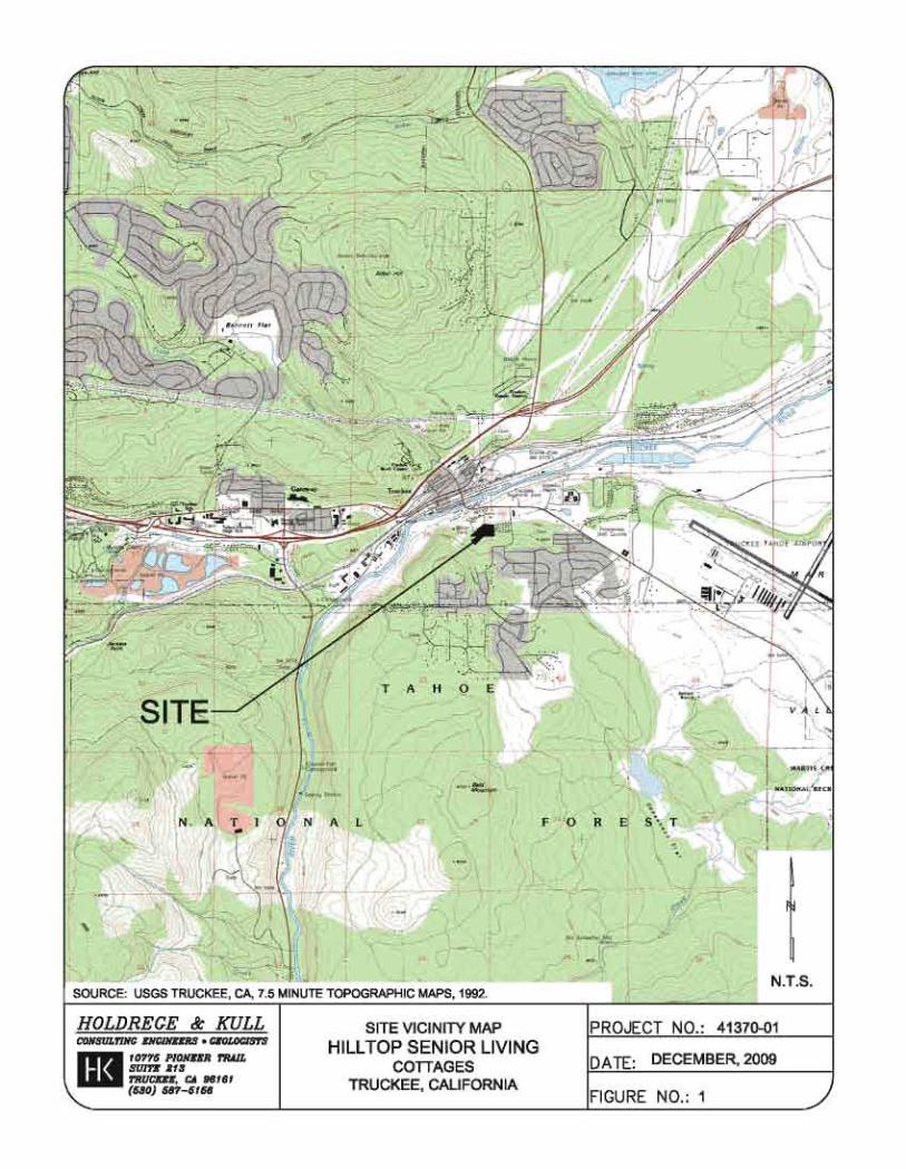
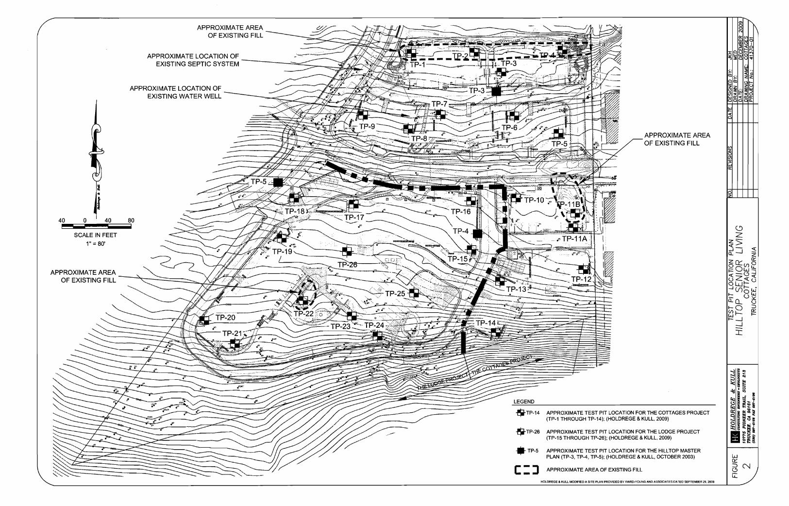
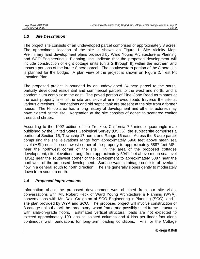
1.3 Site Description The project site consists of an undeveloped parcel comprised of approximately 8 acres. The approximate location of the site is shown on Figure 1, Site Vicinity Map. Preliminary land development plans provided by Ward Young Architecture & Planning and SCO Engineering + Planning, Inc. indicate that the proposed development will include construction of eight cottage units (units 2 through 9) within the northern and eastern portions of the larger 8-acre parcel. The southwestern portion of the 8-acre site is planned for the Lodge. A plan view of the project is shown on Figure 2, Test Pit Location Plan. The proposed project is bounded by an undeveloped 24 acre parcel to the south, partially developed residential and commercial parcels to the west and north, and a condominium complex to the east. The paved portion of Pine Cone Road terminates at the east property line of the site and several unimproved roads traverse the site at various directions. Foundations and old septic tank are present at the site from a former house. The Hilltop area has a long history of development and other structures may have existed at the site. Vegetation at the site consists of dense to scattered conifer trees and shrubs. According to the 1992 edition of the Truckee, California 7.5-minute quadrangle map published by the United States Geological Survey (USGS); the subject site comprises a portion of Section 15, Township 17 north, and Range 16 east. Across the 8-acre parcel comprising the site, elevations range from approximately 5960 feet above mean sea level (MSL) near the southwest corner of the property to approximately 5887 feet MSL near the northwest corner of the site. In the area of the proposed cottages development, site elevations range from approximately 5941 feet above mean sea level (MSL) near the southwest corner of the development to approximately 5887 near the northwest of the proposed development. Surface water drainage consists of overland flow in a general south to north direction. The site generally slopes gently to moderately down from south to north. 1.4 Proposed Improvements Information about the proposed development was obtained from our site visits, conversations with Mr. Robert Heck of Ward Young Architecture & Planning (WYA), conversations with Mr. Dale Creighton of SCO Engineering + Planning (SCO), and a site plan provided by WYA and SCO. The proposed project will involve construction of 8 cottage units that will be three-story, wood-frame and possibly steel-frame structures with slab-on-grade floors. Estimated vertical structural loads are not expected to exceed approximately 100 kips at isolated columns and 4 kips per linear foot along continuous wall foundations for long-term loading conditions. Fills for the Cottage

Project No. 41370-01 Geotechnical Engineering Report for Hilltop Senior Living Cottages Project December 8, 2009 Page 3
Holdrege & Kull
building pads are anticipated to be on the order of 9 to 10 feet. Cuts are generally anticipated to be on the order of 5 to 7 feet and are not expected to exceed 15 feet in the southernmost corner of Unit 4. Appurtenant construction for the cottages project will likely include asphalt concrete paved driveways, paving stone patios and walkways, landscaping, and underground utilities. 2. LITERATURE REVIEW We reviewed available geologic and soil literature in our files to help evaluate geologic and anticipated subsurface conditions at the project site. 2.1 Site Geology We reviewed the Geologic Map of the Lake Tahoe Basin, California and Nevada, by George .J. Saucedo, California Geological Survey, 2005. The geologic map indicates that the south portion of the 8-acre site is underlain by Prosser Creek alluvium of Quaternary age (approximately 1.6 million years before the present). The north portion of the 8-acre site is shown to be underlain by glacial outwash deposits also of Quaternary age. In addition we reviewed a geologic map and report titled Pleistocene History of the Truckee Area, North of Lake Tahoe, California, by Peter W. Birkeland, Stanford University Ph.D. Thesis, 1962. The geologic map indicates that most of the 8-acre site is underlain by Prosser Creek alluvium. The south and southwest portions of the 8-acre site are underlain by volcanic rocks of the Bald Mountain olivine latite formation (Quaternary age) and the northernmost portion of the 8-acre site to be underlain by Quaternary Sherwin glacial till deposits. Based on field reconnaissance performed by our geotechnical engineer, it appears that three separate geologic units underlie the 8-acre site (volcanic rock, Prosser Creek alluvium, and glacial outwash). Most of the cottages project area (Units 2, and 5 to 9) is underlain by glacial outwash deposits that contain a significant amount of boulders. The boulders appear to be approximately 4 to 6 feet in diameter and may be as large as 12 feet in diameter. The southeast corner of the Cottages project area (Units 3 and 4) is underlain by Prosser Creek alluvium. Volcanic rock is exposed at the ground surface above a topographic break near the south property line, adjacent to Unit 4.
Project No. 41370-01 Geotechnical Engineering Report for Hilltop Senior Living Cottages Project December 8, 2009 Page 4
Holdrege & Kull
2.2 Regional Faulting The project is located in a potentially active seismic area. To evaluate the location of mapped faults relative to the project site, we reviewed the following maps:
• Fault Activity Map of California and Adjacent Areas; by Charles W. Jennings, California Department of Conservation, Division of Mines and Geology, 1994.
• Geologic Map of the Chico Quadrangle, California, by G.J. Saucedo and D.L.
Wagner, California Division of Mines and Geology, 1992.
• Pleistocene History of the Truckee Area, North of Lake Tahoe, California, by Peter W. Birkeland, Stanford University Ph.D. Thesis, 1962.
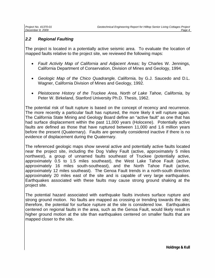
The potential risk of fault rupture is based on the concept of recency and recurrence. The more recently a particular fault has ruptured, the more likely it will rupture again. The California State Mining and Geology Board define an “active fault” as one that has had surface displacement within the past 11,000 years (Holocene). Potentially active faults are defined as those that have ruptured between 11,000 and 1.6 million years before the present (Quaternary). Faults are generally considered inactive if there is no evidence of displacement during the Quaternary. The referenced geologic maps show several active and potentially active faults located near the project site, including the Dog Valley Fault (active, approximately 5 miles northwest), a group of unnamed faults southeast of Truckee (potentially active, approximately 0.5 to 1.5 miles southeast), the West Lake Tahoe Fault (active, approximately 16 miles south-southeast), and the North Tahoe Fault (active, approximately 12 miles southeast). The Genoa Fault trends in a north-south direction approximately 20 miles east of the site and is capable of very large earthquakes. Earthquakes associated with these faults may cause strong ground shaking at the project site. The potential hazard associated with earthquake faults involves surface rupture and strong ground motion. No faults are mapped as crossing or trending towards the site; therefore, the potential for surface rupture at the site is considered low. Earthquakes centered on regional faults in the area, such as the Genoa Fault, would likely result in higher ground motion at the site than earthquakes centered on smaller faults that are mapped closer to the site.
Project No. 41370-01 Geotechnical Engineering Report for Hilltop Senior Living Cottages Project December 8, 2009 Page 5
Holdrege & Kull
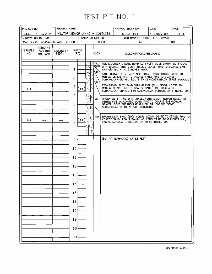
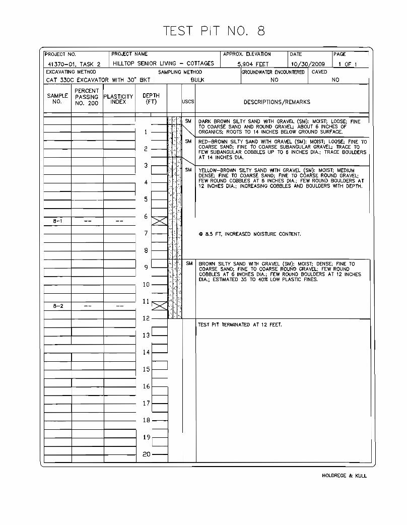
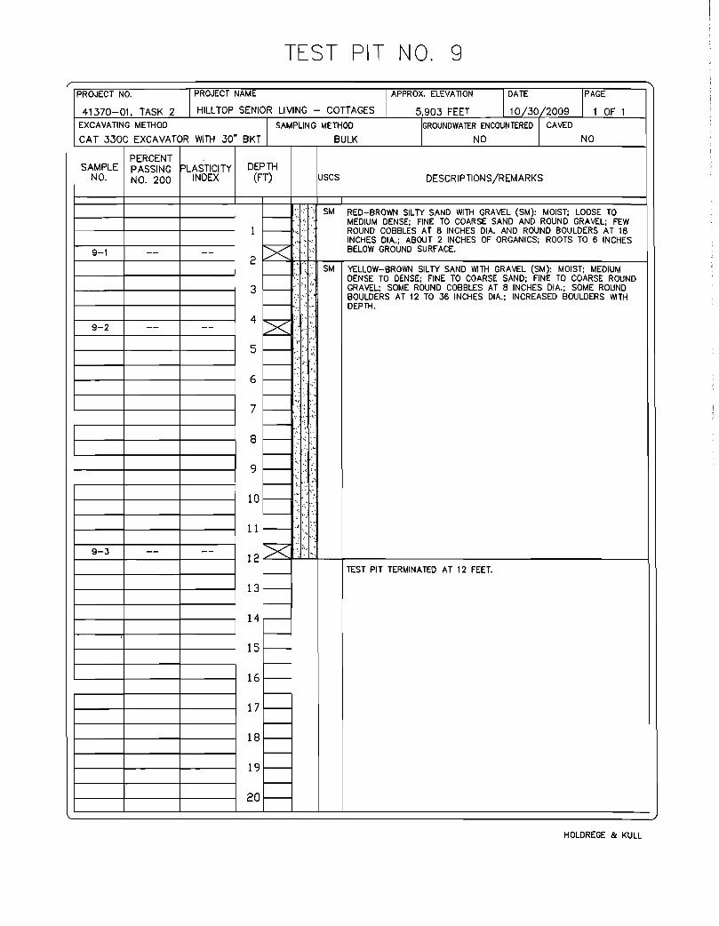
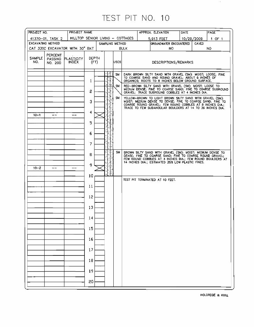
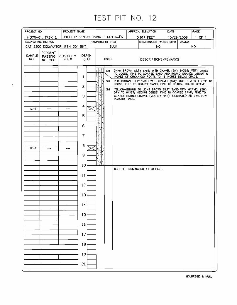
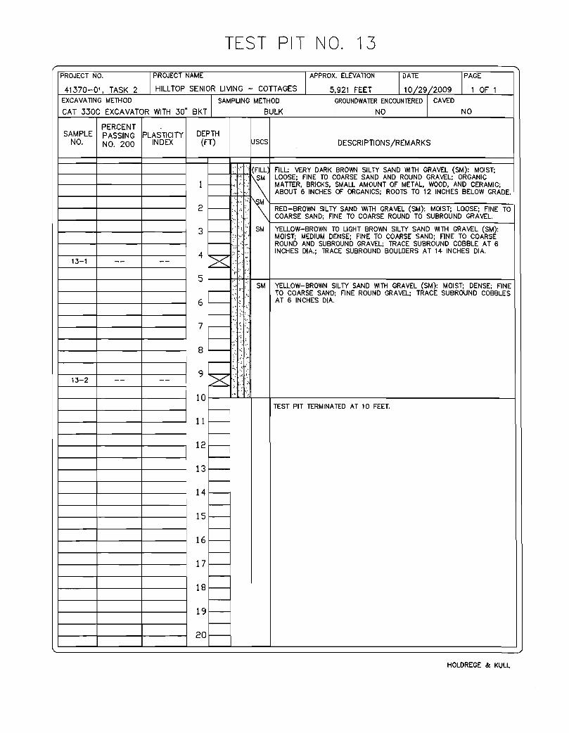
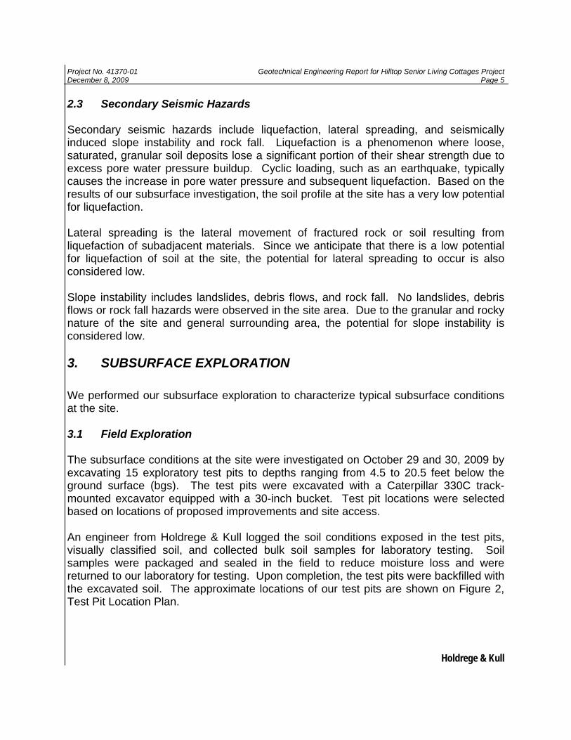
2.3 Secondary Seismic Hazards Secondary seismic hazards include liquefaction, lateral spreading, and seismically induced slope instability and rock fall. Liquefaction is a phenomenon where loose, saturated, granular soil deposits lose a significant portion of their shear strength due to excess pore water pressure buildup. Cyclic loading, such as an earthquake, typically causes the increase in pore water pressure and subsequent liquefaction. Based on the results of our subsurface investigation, the soil profile at the site has a very low potential for liquefaction. Lateral spreading is the lateral movement of fractured rock or soil resulting from liquefaction of subadjacent materials. Since we anticipate that there is a low potential for liquefaction of soil at the site, the potential for lateral spreading to occur is also considered low. Slope instability includes landslides, debris flows, and rock fall. No landslides, debris flows or rock fall hazards were observed in the site area. Due to the granular and rocky nature of the site and general surrounding area, the potential for slope instability is considered low. 3. SUBSURFACE EXPLORATION We performed our subsurface exploration to characterize typical subsurface conditions at the site. 3.1 Field Exploration The subsurface conditions at the site were investigated on October 29 and 30, 2009 by excavating 15 exploratory test pits to depths ranging from 4.5 to 20.5 feet below the ground surface (bgs). The test pits were excavated with a Caterpillar 330C track-mounted excavator equipped with a 30-inch bucket. Test pit locations were selected based on locations of proposed improvements and site access. An engineer from Holdrege & Kull logged the soil conditions exposed in the test pits, visually classified soil, and collected bulk soil samples for laboratory testing. Soil samples were packaged and sealed in the field to reduce moisture loss and were returned to our laboratory for testing. Upon completion, the test pits were backfilled with the excavated soil. The approximate locations of our test pits are shown on Figure 2, Test Pit Location Plan.

Project No. 41370-01 Geotechnical Engineering Report for Hilltop Senior Living Cottages Project December 8, 2009 Page 6
Holdrege & Kull
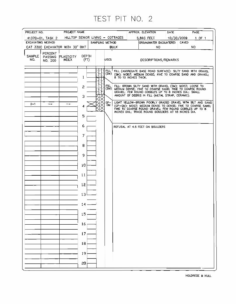
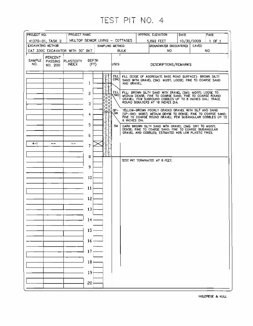
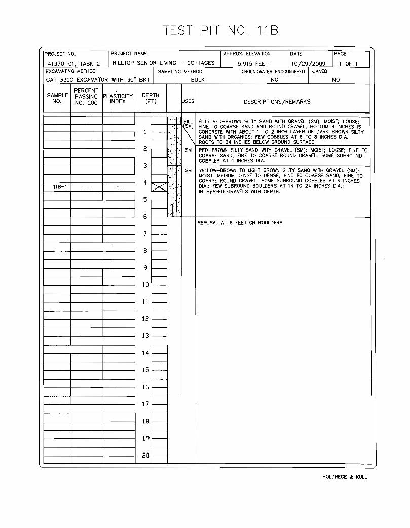
3.2 Subsurface Soil Conditions Near-surface soil encountered in our test pits consisted of 6 to 12 inches of loose silty sand (SM) containing organic material (topsoil) over the majority of the site of the proposed Cottages project. Underlying the silty sand soil, our test pits generally encountered medium dense to dense silty to clayey sand with gravel, cobbles, and boulders to the maximum depth explored of 20.5 feet bgs. Test Pits TP-2, TP-3, TP-11A, and TP-11B met refusal on boulders at 4.5, 8.5, 5 and 6 feet bgs, respectively. Test Pits TP-1, TP-2, TP-3 and TP-4 encountered about 6 to 36 inches of loose to medium dense fill soil along the existing dirt road at the northwestern portion of the proposed Cottages site. A thin layer of fill was also encountered in Test Pit TP-11B located near the east central property line of the Cottages project. More detailed descriptions of the subsurface conditions observed are presented in our Test Pit Logs in Appendix C. 3.3 Groundwater Conditions We did not observe groundwater during our subsurface exploration. However, fluctuations in soil moisture content and groundwater levels should be anticipated depending on precipitation, irrigation, runoff conditions and other factors. Based on our experience in the project area, seasonal saturation of near-surface soil should be anticipated, especially during and immediately after seasonal snowmelt. Refusal on boulders was encountered in Test Pits TP-2, TP-3, TP-11A and TP-11B at depths ranging from approximately 4.5 to 8.5 feet below existing grades. In addition, friable, volcanic rock was encountered in Test Pit TP-14 at a depth of approximately 14 feet below grade. Depending on rainfall, runoff conditions, and other factors, perched groundwater could develop above onsite boulders and volcanic rock. Given the steep topography in the southern portion of the site, seasonal saturation of near surface soil and perched groundwater on near-surface rock may result in significant groundwater flow through the face of cuts made for retaining walls or site grading. Perched groundwater may cause moisture migration through concrete slab-on-grade floors, degradation of asphalt concrete pavements, and other adverse conditions. Mitigation measures such as gravel underdrains, elevated building pads, trench drains, or other methods may be required to intercept shallow groundwater or reduce potential adverse effects on project features. We recommend the project civil engineer in conjunction with the project geotechnical engineer review the subsurface information available within this report and revealed during site preparation in order to develop appropriate measures consistent with design considerations beyond the current scope of this study.
Project No. 41370-01 Geotechnical Engineering Report for Hilltop Senior Living Cottages Project December 8, 2009 Page 7
Holdrege & Kull
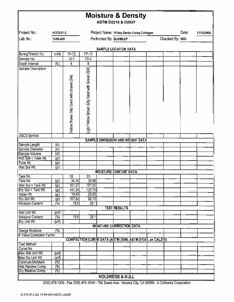
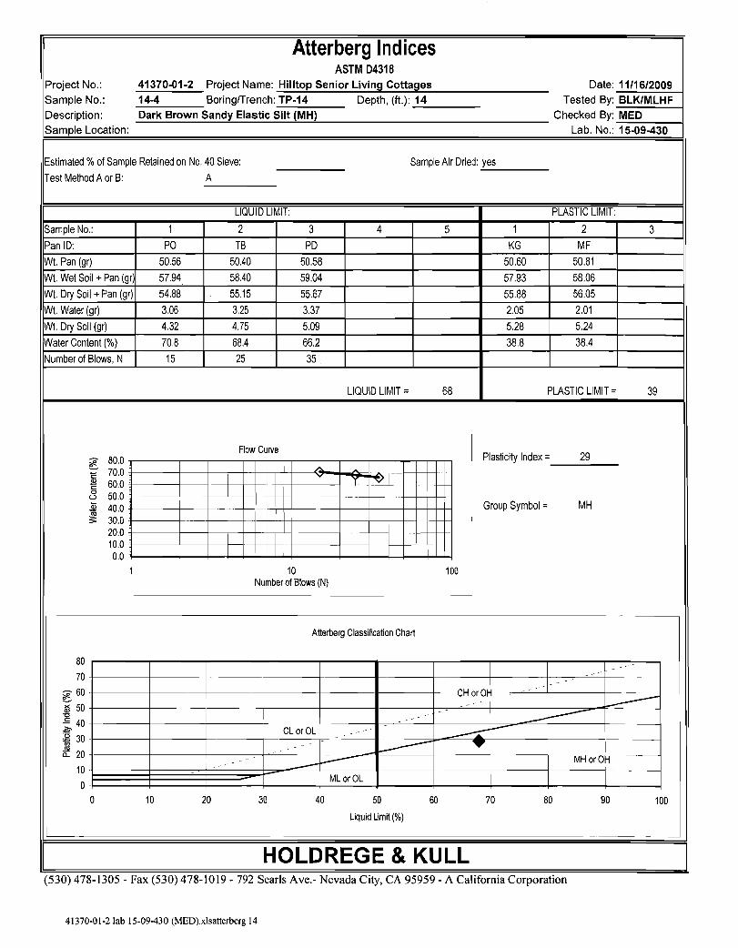
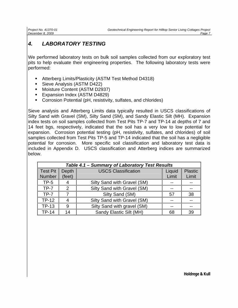
4. LABORATORY TESTING We performed laboratory tests on bulk soil samples collected from our exploratory test pits to help evaluate their engineering properties. The following laboratory tests were performed:
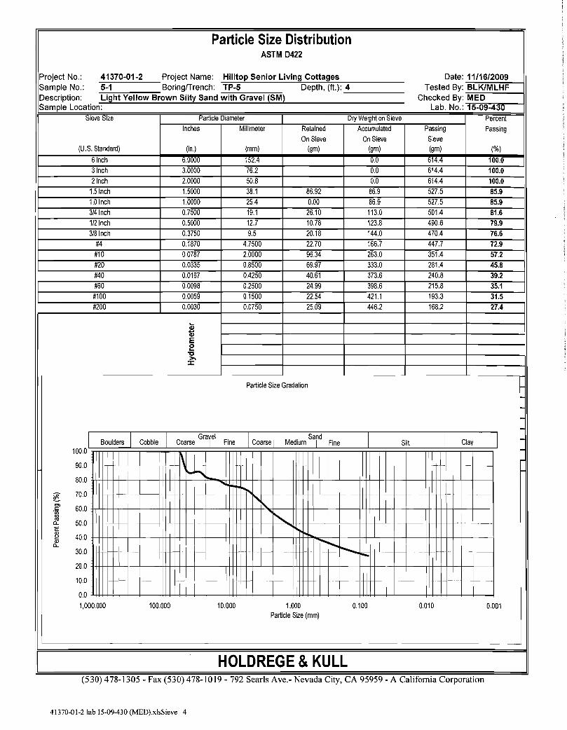
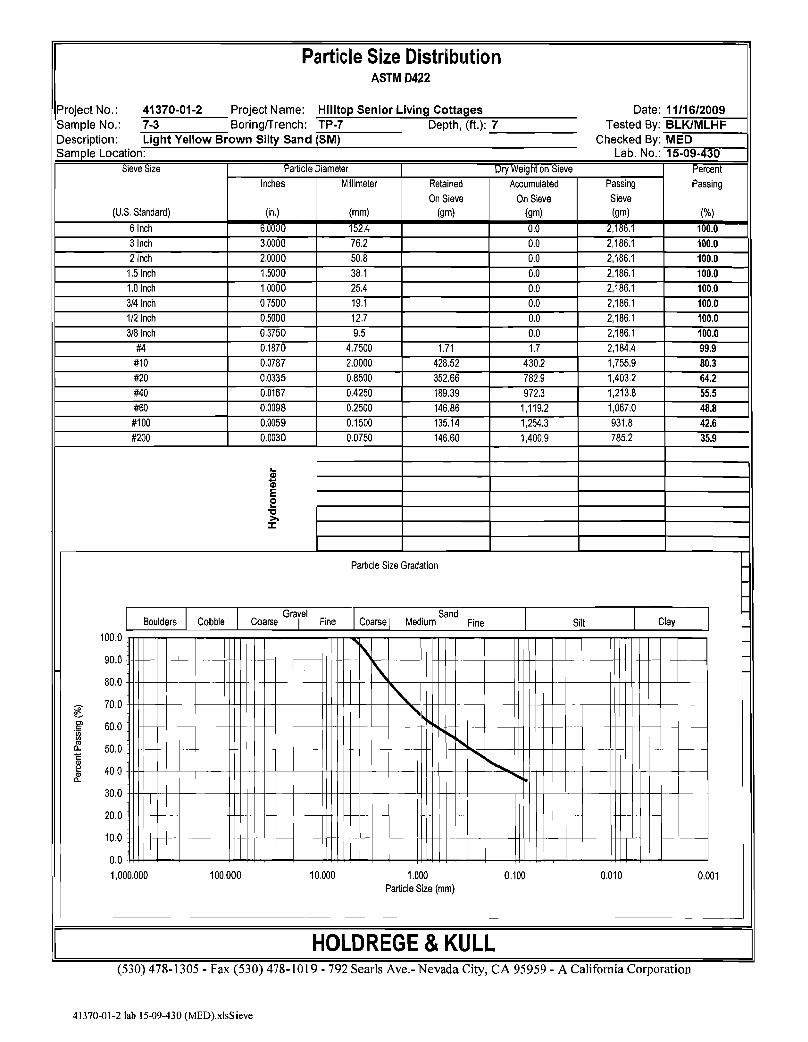
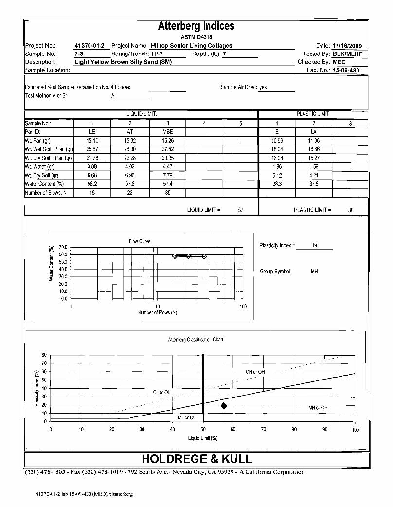
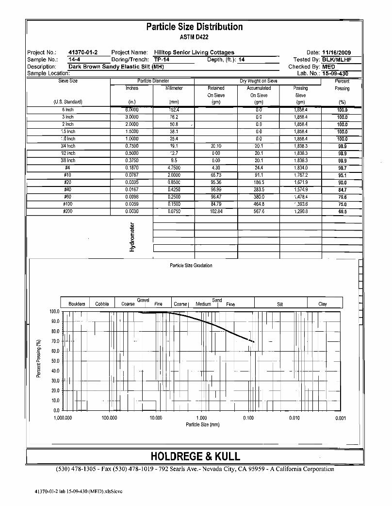
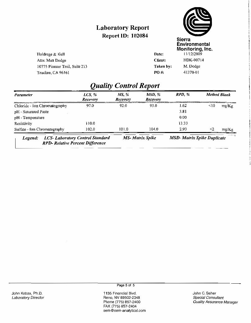
Atterberg Limits/Plasticity (ASTM Test Method D4318) Sieve Analysis (ASTM D422) Moisture Content (ASTM D2937) Expansion Index (ASTM D4829) Corrosion Potential (pH, resistivity, sulfates, and chlorides)
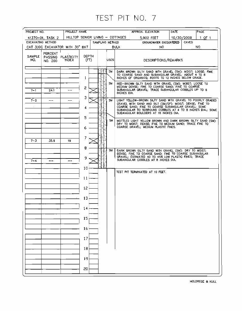
Sieve analysis and Atterberg Limits data typically resulted in USCS classifications of Silty Sand with Gravel (SM), Silty Sand (SM), and Sandy Elastic Silt (MH). Expansion index tests on soil samples collected from Test Pits TP-7 and TP-14 at depths of 7 and 14 feet bgs, respectively, indicated that the soil has a very low to low potential for expansion. Corrosion potential testing (pH, resistivity, sulfates, and chlorides) of soil samples collected from Test Pits TP-5 and TP-14 indicated that the soil has a negligible potential for corrosion. More specific soil classification and laboratory test data is included in Appendix D. USCS classification and Atterberg indices are summarized below.
Table 4.1 – Summary of Laboratory Test Results Test Pit Number
Depth (feet)
USCS Classification Liquid Limit
Plastic Limit
TP-5 4 Silty Sand with Gravel (SM) -- -- TP-7 2 Silty Sand with Gravel (SM) -- -- TP-7 7 Silty Sand (SM) 57 38
TP-12 4 Silty Sand with Gravel (SM) -- -- TP-13 9 Silty Sand with gravel (SM) -- -- TP-14 14 Sandy Elastic Silt (MH) 68 39

Project No. 41370-01 Geotechnical Engineering Report for Hilltop Senior Living Cottages Project December 8, 2009 Page 8
Holdrege & Kull
5. CONCLUSIONS The following conclusions are based on our field observations, laboratory test results, and our experience in the project area.
1. Soil conditions encountered in our field investigation generally consisted of medium dense to dense granular to very stiff to hard fine-grained soil types of low plasticity that should provide suitable foundation support for the proposed structures on conventional shallow spread foundations. No highly plastic, compressible, or potentially expansive soil was encountered.
2. Small areas of fill are located near the north and east property lines. Along the
northern property line (Units 8 and 9), the fill ranges from approximately 0.5 to 2.75 feet thick. A small stockpile of fill (approximately 60 feet long by 35 feet wide by 4 feet high) is located near the east central property line. Test Pit TP- 11B, excavated adjacent to the fill stockpile encountered fill to a depth of approximately 0.5 feet below grade. Due to the partially developed nature of the site, it is possible that other areas of fill may be present at locations out side our test pits. In addition, small, scattered stockpiles of construction debris and other miscellaneous garbage were observed on the ground surface throughout the site. Due to the potential for excess settlement, the existing fill will not be suitable for support of structures. We have provided recommendations in the “Grading” section below for removing and if necessary replacing the existing fill soil with compacted structural fill.
3. We observed an abandoned septic tank and leach field near the northwest
corner of the site. In addition, a small wooden shack containing an electrical panel and possible well pump is located approximately 100 feet southwest of the septic tank and may be affiliated with a water well. These items should be removed and disposed of off-site; existing wells should be abandoned in accordance with applicable regulatory requirements. Existing utility pipelines which extend beyond the limits of the proposed construction that will be abandoned in-place should be plugged with cement grout to prevent migration of soil and/or water. All excavations resulting from removal activities should be cleaned of loose or disturbed material (including all previously-placed backfill) and dish-shaped to permit access for compaction equipment.
4. The Caterpillar 330C excavator used for our field exploration encountered refusal
on boulders in the north, northeast, and east central portions of the site. Depth to refusal varied from 4.5 feet in the vicinity of proposed Unit 8 (Test Pit TP-2), 5 to 6 feet in the vicinity of Unit 2 (Test Pits TP-11A and 11B), and 8.5 feet in the vicinity of Unit 9 (Test Pit TP-3). Boulders were observed across the ground

Project No. 41370-01 Geotechnical Engineering Report for Hilltop Senior Living Cottages Project December 8, 2009 Page 9
Holdrege & Kull
surface in the north and east central portions of the site. Confined excavations for footings and under ground utilities that extend into boulders will likely be difficult. A significant amount of boulders and over-sized material should be anticipated in on site excavations. A large track-mounted excavator equipped with a ripper tooth or hydraulic hammer may be required in these areas, a “thumb” attachment may ease boulder removal at the site. With the exception of the organic surface soil, site soil is generally suitable for reuse as structural fill; however, processing to remove oversized material will likely be necessary.
5. Groundwater was not encountered during our subsurface exploration to the
maximum depth explored. However, depending on final site grades, rainfall, and/or irrigation practices, perched groundwater could develop above onsite rock and boulders and cause moisture intrusion through concrete slabs-on-grade, degradation of asphalt concrete pavements, and other adverse conditions. Consequently, positive surface water drainage will be important across the site to reduce the potential for near-surface water causing moisture migration through concrete slabs-on-grade, degradation of asphalt concrete pavements, and contributing to frost heave and other adverse conditions. We have provided recommendations to reduce the potential for these adverse effects in the “Recommendations” section of this report.
6. Site soil should provide adequate pavement support. However, seasonal
saturation of near-surface soil should be considered in the design of pavement areas. Subdrain construction under pavement areas should be considered to reduce saturation.
7. Numerous tree roots should be anticipated in near-surface site soil located in
wooded areas. Raking or hand picking to remove tree roots in fill, road and foundation areas may be necessary.
Project No. 41370-01 Geotechnical Engineering Report for Hilltop Senior Living Cottages Project December 8, 2009 Page 10
Holdrege & Kull
6. RECOMMENDATIONS The following geotechnical engineering recommendations are based on our understanding of the project as currently proposed, our field observations, the results of our laboratory tests, engineering analysis, and our experience in the project area. 6.1 GRADING The following sections present our recommendations for site clearing and grubbing, preparation for and placement of fill material, temporary excavation and cut/fill slope grading, erosion control measures, utility trench construction, construction dewatering, surface water drainage, plan review, and construction monitoring.
6.1.1 Clearing and Grubbing Areas proposed for fill placement, road and driveway construction, parking lot, and building areas should be cleared and grubbed of vegetation and other deleterious materials. Existing vegetation, organic topsoil, and any debris should be stripped and hauled offsite or stockpiled outside the construction limits. Based on our subsurface exploration, we expect that 6 inches may be used as a reasonable estimate for average depth of stripping. Organic surface soil may be stockpiled for future use in landscape areas, but is not suitable for use as structural fill. We anticipate that the actual depth of stripping will vary across the site and may be greater in wooded areas. Man-made debris, existing fill, and backfill soil in our exploratory test pits or any other onsite excavations should be overexcavated to underlying, competent material and replaced with compacted structural fill. Grubbing may be required where concentrations of organic soil or tree roots are encountered during site grading. All existing fill should be removed in areas that will support foundation elements, earth retention structures, concrete slabs-on-grade, and pavement sections. Based on our field observations the depth of existing fill ranges from 0.5 to 2.75 feet across in the east and north areas of the site, respectively. An approximately 300 cubic yard, 4 foot high, stockpile of fill is present near the east central property line at the site. The existing fill should either be replaced with compacted structural fill or improvements may be founded directly on properly prepared underlying native soil. The existing fill material will be suitable for re-use as engineered fill material provided any debris exceeding 8 inches maximum dimension and all organic or deleterious material are removed and disposed off-site. Preparation of the subgrade exposed by overexcavation and requirements for engineered fill should be in accordance with recommendations provided below.
Project No. 41370-01 Geotechnical Engineering Report for Hilltop Senior Living Cottages Project December 8, 2009 Page 11
Holdrege & Kull
All rocks greater than 8 inches in greatest dimension (oversized rock) should be removed from the top 12 inches of soil, if encountered. Oversized rock may be used in landscape areas, rock faced slopes, or removed from the site. Oversized rock should not be placed in fill without prior approval by the project geotechnical engineer.
6.1.2 Preparation for Fill Placement Prior to fill placement, all areas of existing fill material, man-made debris, or backfill soil should be removed to expose non-expansive native soil as discussed in the previous section. Where fill placement is planned, the near-surface soil should be scarified to a depth of about 12 inches below existing ground surface or to competent material and then uniformly moisture conditioned to within 2 percent of the ASTM D1557 optimum moisture content. Areas to receive fill should be compacted with appropriate compaction equipment to at least 90 percent of the maximum dry density per ASTM D1557, and proof rolled with a loaded, tandem-axle truck under the observation of a representative of Holdrege & Kull. Any areas that exhibit pumping or rutting should be overexcavated and replaced with compacted fill placed according to the recommendations below.
6.1.3 Fill Placement Material used for fill construction should consist of uncontaminated, predominantly granular, non-expansive native soil or approved import soil. Engineered fill should consist of granular material, nearly free of organic debris, with liquid limit of less than 40, a plasticity index less than 15, 100 percent passing the 8-inch sieve, and less than 40 percent passing the No. 200 sieve. In general, near-surface, on-site soil types similar to those encountered in our test pits may be used in a fill provided all oversized material is removed prior to placement and compaction. Rock used in fill should be broken into fragments no larger than 8 inches in diameter. Rocks larger than 8 inches are considered oversized material and should be stockpiled for offhaul, later use in rock faced slopes, or placement in landscape areas. Imported fill material should be predominantly granular, non-expansive, and free of deleterious or organic material. Import material that is proposed for use onsite should be submitted to Holdrege & Kull for approval and laboratory analysis at least 72 hours prior to import. If site grading is performed during periods of wet weather, near-surface site soil may be significantly above optimum moisture content. Soil at greater depths may be above optimum moisture content at all times of the year. These conditions could hamper
Project No. 41370-01 Geotechnical Engineering Report for Hilltop Senior Living Cottages Project December 8, 2009 Page 12
Holdrege & Kull
equipment maneuverability and efforts to compact fill materials to the recommended compaction criteria. Fill material may require drying to facilitate placement and compaction, particularly during or following the wet season or spring snowmelt. Suitable compaction results may be difficult to obtain without processing the soil (e.g., discing during favorable weather, covering stockpiles during periods of precipitation, etc.). Fill should be uniformly moisture conditioned to within 2 percent of optimum moisture content and placed in maximum 8-inch thick, loose lifts (layers) prior to compacting. Fill should be compacted to at least of 90 percent of the maximum dry density per ASTM D1557. The upper 8 inches of fill in paved areas should be compacted to at least 95 percent of the maximum dry density per ASTM D1557. Moisture content, dry density, and relative compaction of fill should be evaluated by our firm at regular intervals during fill placement. The earthwork contractor should assist our representative by preparing test pads with the onsite earth moving equipment. Fill material with more than 30 percent rock larger than ¾-inch is not testable using conventional compaction testing equipment. We recommend that a procedural approach, or method specification, be used for quality assurance during rock fill placement rather than a specified relative compaction. The procedural requirements will depend on the equipment used, as well as the nature of the fill material, and will need to be determined by the geotechnical engineer on site. Based on our experience in the area, we anticipate that the procedural specification will require a minimum of six passes with a Cat 563 or similar, self-propelled vibratory compactor to compact a maximum 8-inch thick loose lift. Processing or screening of the fill may be required to remove rocks larger than 8-inches in maximum dimension. Continuous observation by a representative of Holdrege & Kull will be required during fill placement to confirm that procedural specifications have been met. Differential fill depths beneath the structures should not exceed 5 feet. For example, if the maximum fill depth is 8 feet across a building pad, the minimum fill depth beneath that pad should not be less than 3 feet. If a cut-fill building pad were used in this example, the cut portion would need to be overexcavated 3 feet and rebuilt with compacted fill.
6.1.4 Cut/Fill Slope Grading Site soil is generally anticipated to be granular material. Permanent cut and fill slopes at the subject site should be stable at inclinations of 2H:1V or flatter. Steeper slopes may be possible at the site provided slopes are protected from excessive erosion. Recommendations for cut/fill slopes steeper than 2H:1V may be provided by request.
Project No. 41370-01 Geotechnical Engineering Report for Hilltop Senior Living Cottages Project December 8, 2009 Page 13
Holdrege & Kull
Fill should be placed in horizontal lifts to the lines and grades shown on the project plans. Slopes should be constructed by overbuilding the slope face and then cutting it back to the design slope gradient. Fill slopes should not be constructed or extended horizontally by placing soil on an existing slope face and/or compacted by track walking. Equipment width keyways and benches should be provided where fill is placed on side-slopes with gradients steeper than 5H:1V. Benching must extend through loose surface soil into suitable material, and be performed at intervals such that no loose soil is left beneath the fill. Holdrege & Kull should observe keyways and benches prior to fill placement. The upper two to five feet of cut slopes should be rounded into the existing terrain above the slope to remove loose material and produce a contoured transition from cut face to natural ground. Scaling to remove unstable cobbles and boulders may be necessary. Fill slopes should be compacted as recommended for the placement of engineered fill. The upper 4 to 8 inches may be scarified to help promote revegetation.
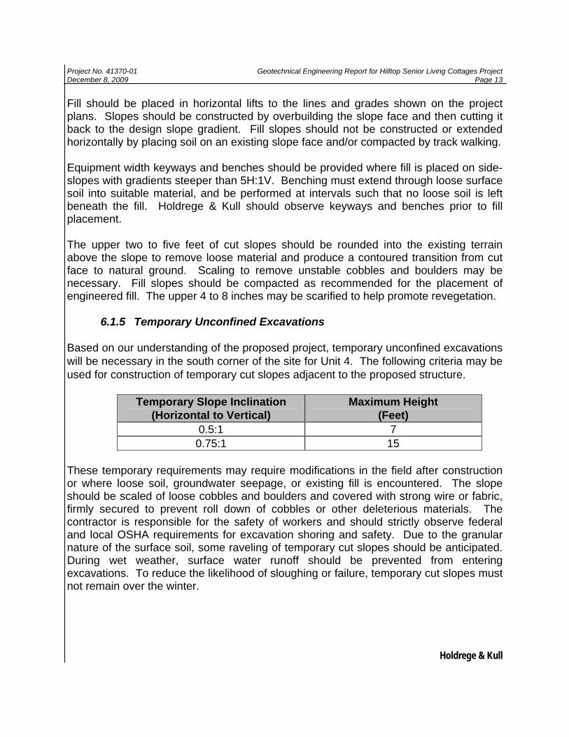
6.1.5 Temporary Unconfined Excavations Based on our understanding of the proposed project, temporary unconfined excavations will be necessary in the south corner of the site for Unit 4. The following criteria may be used for construction of temporary cut slopes adjacent to the proposed structure.
Temporary Slope Inclination (Horizontal to Vertical)
Maximum Height (Feet)
0.5:1 7 0.75:1 15
These temporary requirements may require modifications in the field after construction or where loose soil, groundwater seepage, or existing fill is encountered. The slope should be scaled of loose cobbles and boulders and covered with strong wire or fabric, firmly secured to prevent roll down of cobbles or other deleterious materials. The contractor is responsible for the safety of workers and should strictly observe federal and local OSHA requirements for excavation shoring and safety. Due to the granular nature of the surface soil, some raveling of temporary cut slopes should be anticipated. During wet weather, surface water runoff should be prevented from entering excavations. To reduce the likelihood of sloughing or failure, temporary cut slopes must not remain over the winter.
Project No. 41370-01 Geotechnical Engineering Report for Hilltop Senior Living Cottages Project December 8, 2009 Page 14
Holdrege & Kull
6.1.6 Best Management Practices and Erosion Control Based on our site observations and experience in the area, site soil will be moderately to highly susceptible to erosion, particularly on steep, unprotected slopes. Best management practices (BMPs) should be incorporated into the design and construction of this project. A reference regarding appropriate BMPs is the “Erosion and Sediment Control Guidelines for Developing Areas of the Sierra Foothills and Mountains”, prepared by the High Sierra Resource Conversation and Development Council, 1991. The California Regional Water Quality Control Board, Lahontan Region, Best Management Practices Plan is anther source of BMPs. Erosion and sediment control measures can be categorized as temporary or permanent. Temporary measures should be installed to provide short-term protection until the permanent measures are installed and effective. Temporary erosion control structures are designed to slow runoff velocity and intercept suspended sediment to prevent sediment discharge from the construction area while allowing runoff to continue down gradient. Typical temporary measures include properly installed silt fences, straw bales, sediment logs, water bars, detention basins, covering of exposed soil, channel linings, and inlet protection. Following completion of construction and planting/seeding, temporary erosion control measures may be left in place, possibly for a complete growing season. Temporary erosion control measures require regular inspection and maintenance. The selection and sizing of a sediment barrier is dependent on slope angle, slope length, and soil type. Sediment barriers should be installed down gradient and at the edges of all disturbed areas and around topsoil and spoil piles where and when necessary. Sediment barriers should be placed as needed on slope contours, within small drainages, and in gently sloping swales. Berms, waterbars and ditches should be used to divert or channel storm water runoff away from sensitive, disturbed or construction areas. Waterbars are intended to slow water traveling down a disturbed slope and divert water off disturbed soil into adjacent stable often well-vegetated areas. Where possible, interceptor ditches and waterbars should take advantage of existing terrain and vegetation to divert runoff before it reaches slopes and disturbed areas. Waterbars should be constructed above and within disturbed areas. The spacing for temporary waterbars should be as needed to divert water off the disturbed areas. Waterbars should be located adjacent to non-erodible (vegetated or rocky) receiving areas. If stable receiving areas are not present, flow energy dissipaters or “J-hook” shaped silt fences should be positioned at the waterbar outlet. In highly erodible soils, waterbar ditches should be protected by temporary lining or by decreasing waterbar spacing and length of flow line slopes.

Project No. 41370-01 Geotechnical Engineering Report for Hilltop Senior Living Cottages Project December 8, 2009 Page 15
Holdrege & Kull
Permanent erosion and sediment control measures may include rock slope protection (RSP), rock lined ditches and inlet/outlet protection, rock energy dissipaters, infiltration/detention basins, and vegetation. We recommend Low Impact Development (LID) methods for the BMPs. LID is a storm water management and land development strategy applied at the parcel and subdivision scale that emphasizes conservation and use of on-site natural features integrated with engineered, small scale hydrologic controls to more closely mimic natural hydrologic functions. The additional storm water runoff created by construction of impervious areas such as driveways and roofs should be retained or detained on site. Common methods of retention and detention include drywells, infiltration trenches, bioretention gardens, porous pavement, grassed swales, infiltration basins, gravel mulch and water spreading. Integrating these methods throughout the project will help protect water quality and reduce storm water runoff. All areas disturbed by construction should be revegetated, and existing vegetation should be protected and undisturbed where possible. Revegetation should consist of native brush and grass species. Slope faces should be temporarily protected against erosion resulting from direct rain impact and melting snow using the methods described above until permanent vegetation can be established.
6.1.7 Underground Utility Trenches We anticipate that the contractor will be able to excavate underground utility trenches using conventional earthmoving equipment across the majority of the site. However, trenches in the north and west portions of the site will likely encounter large boulders. In addition, moderately strong volcanic rock should be anticipated in the south portion of the site in the area of proposed Unit 4. The Caterpillar 330C excavator used in our field exploration encountered refusal on boulders at depths of 4.5 to 8 feet below existing grade in the northwest part of the site, and at depths of 5 to 6 feet in the east central portion of the site. Based on the excavation conditions encountered in our test pits, we anticipate that a track mounted excavator equipped with a ripper or hydraulic hammer will be required below about four feet in the northwest portion of the site. An excavator with a “thumb” attachment may increase ease of boulder removal at the site.
Due to the granular nature of the onsite soil, we expect that some caving and sloughing of utility trench sidewalls will occur. The California Occupational Safety and Health Administration (OSHA) requires all utility trenches deeper than 5 feet bgs be shored with bracing equipment or sloped back prior to entry.
Although we did not observe groundwater in our exploratory test pits, shallow subsurface seepage may be encountered in trench excavations, particularly if utility trenches are excavated during the spring or early summer. The earthwork contractor
Project No. 41370-01 Geotechnical Engineering Report for Hilltop Senior Living Cottages Project December 8, 2009 Page 16
Holdrege & Kull
may need to employ dewatering methods as discussed in the Construction Dewatering section below to excavate, place and compact trench backfill materials.
Soil used as trench backfill should not contain rocks greater than 3 inches in maximum dimension. Trench backfill should consist of uniformly moisture conditioned soil and be placed in maximum 8-inch thick loose lifts prior to compacting. Unless otherwise specified by the applicable local utility district, pipe bedding and trench backfill should be compacted to at least 90 percent of the maximum dry density per ASTM D1557. Trench backfill placed within 8 inches of subgrade in building, road and parking areas should be compacted to a minimum relative compaction of 95 percent of the maximum dry density per ASTM D1557. The moisture content, density and relative compaction of fill should be tested by Holdrege & Kull at regular intervals during fill placement.
6.1.8 Construction Dewatering During our subsurface exploration, we did not encounter groundwater seepage in our exploratory test pits. If grading is performed during or immediately following the wet season or spring snowmelt, seepage may be encountered during grading. We should observe those conditions and provide site specific subsurface drainage recommendations. The following recommendations are preliminary and are not based on a groundwater flow analysis. We anticipate that dewatering of excavations can be performed by gravity or by constructing sumps to depths below the excavation and removing water with pumps. To maintain stability of the excavation when placing and compacting the trench backfill, groundwater levels should be drawn down a minimum of 2 feet below the lowest point of the excavation.
If seepage is encountered during trench excavation, it may be necessary to remove underlying saturated soil and replace it with free draining, open-graded crushed rock. Soil backfill may be placed after backfilling with drain rock to an elevation higher than encountered groundwater.
6.1.9 Surface Water Drainage Based on our observations and past experience with geotechnical investigations in the project vicinity, there is a relatively high potential for seasonal saturation of near-surface soil and groundwater seepage into the foundation areas. In addition, at the time of our field investigation, weathered volcanic rock (sandy elastic silt) was encountered near the south corner of site (Unit 4) at a depth of approximately 14 feet below grade. Depending on final site grades, rainfall, irrigation practices, and other factors beyond the scope of this study, perched groundwater could develop above onsite volcanic rock.
Project No. 41370-01 Geotechnical Engineering Report for Hilltop Senior Living Cottages Project December 8, 2009 Page 17
Holdrege & Kull
Near-surface and perched groundwater may result in moisture intrusion through concrete floor slabs, degradation of asphalt concrete pavements, increased frost heave and other adverse conditions. Final elevations at the site should be planned so that drainage is directed away from all foundations and pavements. Ponding of surface water should not be allowed near pavements or structures. Final grade in structural areas should be sloped such that surface water drains away from buildings at a minimum 5 percent slope for a minimum horizontal distance of 10 feet. If physical obstructions or lot lines prohibit 10 feet of horizontal distance, a 5 percent slope should be constructed towards a drainage swale or other conveyance system that diverts water away from the foundation. Infiltration of roof or pavement runoff should not be allowed within 10 feet of structures. Paved areas should be sloped away from structures a minimum of 2 percent and drainage gradients should be maintained to carry all surface water to a properly designed infiltration or detention basin. Drains should be constructed on the upslope side of exterior foundations. Drains should extend to a properly designed infiltration gallery. Recommended subsurface drain locations can be provided at the time of construction and when foundation elevations are known. All foundation and slab-on-grade concrete should have a water to cement ratio of 0.45 or less. Underslab or blanket drains should be considered in floor pavement areas to reduce moisture transmission through the floor and help maintain subgrade support. If open-graded gravel or other permeable material is used for underground utilities, the trench should slope away from the structure or the potential flow path should be plugged with a less permeable material at the exterior of the foundation. All utility pipes should have sealed joints. Roof drip-lines should be protected from erosion with a gravel layer and riprap. Roof downspouts should be directed to a closed collector pipe that discharges flow to positive drainage. Backfill soil placed adjacent to building foundations should be placed and compacted such that water is not allowed to pond or infiltrate. Backfill should be free of deleterious material and placed and compacted in accordance with the above earthwork recommendations.
6.1.10 Plan Review and Construction Monitoring Construction monitoring includes review of plans and specifications and observation of onsite activities during construction as described below. We should review final grading and foundation plans prior to construction to evaluate whether our recommendations
Project No. 41370-01 Geotechnical Engineering Report for Hilltop Senior Living Cottages Project December 8, 2009 Page 18
Holdrege & Kull
have been implemented and to provide additional and/or modified recommendations, if necessary. We also recommend that our firm be retained to provide construction monitoring and testing services during site grading, foundation, retaining wall, underground utility and road construction to observe subsurface conditions with respect to our engineering recommendations. 6.2 Structural Improvement Design Criteria The following sections provide design criteria for foundations, seismic design, slabs-on-grade, retaining walls, and pavement sections.
6.2.1 Foundations Our opinion is that shallow spread foundations are suitable for support of the proposed structures. The following paragraphs discuss foundation design parameters and construction recommendations. Exterior foundations should be embedded a minimum of 18 inches below the lowest adjacent exterior finish grade for frost protection and confinement. The bottom of interior footings should be at least 12 inches below lowest adjacent finish grade for confinement. Reinforcing steel requirements for foundations should be determined by the project structural engineer.
Foundations founded in competent, undisturbed native soil or compacted fill may be designed using an allowable bearing capacity of 3,500 psf for dead plus live loads. An additional increase of 500 psf per foot of additional embedment (beyond the minimum 18 inches) may also be used, up to a limiting value of 5,000 psf. Allowable bearing pressures may be increased by 33 percent for transient loading such as wind or seismic loads.
Resistance to lateral loads (including transient loads) may be provided by frictional resistance between the bottom of concrete foundations and the underlying soil, and by passive soil pressure against the sides of foundations. Due to potential variability of soil consistency at finish grade, potential surface soil desiccation and disturbance, we recommend the upper 6 inches of soil be neglected when estimating lateral resistance. Lateral resistance derived from passive earth pressure can be modeled as a triangular pressure distribution ranging from 0 psf at six-inches below the ground surface to a maximum of 330d psf, where d equals the depth of the foundation in feet. A coefficient of friction of 0.35 may be used between poured-in-place concrete foundations and the underlying native soil.
Project No. 41370-01 Geotechnical Engineering Report for Hilltop Senior Living Cottages Project December 8, 2009 Page 19
Holdrege & Kull
Total settlement of individual foundations will vary depending on the plan dimensions of the foundation and actual structural loading. Based on anticipated foundation dimensions and loads, we estimate that total post-construction settlement of footings designed and constructed in accordance with our recommendations will be on the order of ½-inch. Differential settlement between similarly loaded, adjacent footings is expected to be less than ¼ -inch, provided footings are founded on similar materials (e.g., all on engineered fill, native soil, or rock). Differential settlement between adjacent footings founded on dissimilar materials (e.g., one footing on soil and an adjacent footing on rock) may approach the maximum anticipated total settlement. Settlement of foundations is expected to occur rapidly and should be essentially complete shortly after initial application of loads.
Loose material remaining in footing excavations should be removed to expose firm, unyielding material or compacted to at least 90 percent relative compaction. Footing excavations should be moistened prior to placing concrete to reduce risk of problems caused by wicking of moisture from curing concrete. Holdrege & Kull should observe footing excavations prior to reinforcing steel and concrete placement.
6.2.2 Seismic Design Criteria
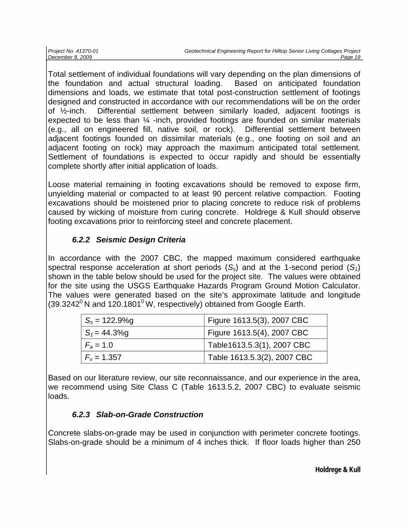
In accordance with the 2007 CBC, the mapped maximum considered earthquake spectral response acceleration at short periods (Ss) and at the 1-second period (S1) shown in the table below should be used for the project site. The values were obtained for the site using the USGS Earthquake Hazards Program Ground Motion Calculator. The values were generated based on the site’s approximate latitude and longitude (39.32420 N and 120.18010 W, respectively) obtained from Google Earth. Based on our literature review, our site reconnaissance, and our experience in the area, we recommend using Site Class C (Table 1613.5.2, 2007 CBC) to evaluate seismic loads.
6.2.3 Slab-on-Grade Construction Concrete slabs-on-grade may be used in conjunction with perimeter concrete footings. Slabs-on-grade should be a minimum of 4 inches thick. If floor loads higher than 250
Ss = 122.9%g Figure 1613.5(3), 2007 CBC S1 = 44.3%g Figure 1613.5(4), 2007 CBC Fa = 1.0 Table1613.5.3(1), 2007 CBC Fv = 1.357 Table 1613.5.3(2), 2007 CBC
Project No. 41370-01 Geotechnical Engineering Report for Hilltop Senior Living Cottages Project December 8, 2009 Page 20
Holdrege & Kull
psf, intermittent live loads, or vehicle loads are anticipated, the project structural engineer should provide slab thickness and steel reinforcing requirements.
Prior to constructing concrete slabs, the upper 8 inches of slab subgrade should be scarified, uniformly moisture conditioned to within 2 percent of optimum moisture content and compacted to at least 90 percent of the maximum dry density per ASTM D1557. Scarification and recompaction may not be required if floor slabs are placed directly on undisturbed compacted structural fill. Due to the potential for seasonal saturation of near-surface soil and to reduce the potential for moisture intrusion, the project architect and/or owner should consider constructing a drain beneath concrete slabs-on-grade that will enclose livable space. Subdrains should consist of a minimum of 4-inches of clean crushed gravel placed over native subgrade with a 4-inch diameter perforated drain pipe. The drain pipe should be placed perforations face down and sloped to drain water from beneath the slab to a properly constructed infiltration gallery or detention basin. A minimum of one pipe should be installed in each area of the slab surrounded by continuous perimeter foundation elements. Slabs should be underlain by at least 4 inches of Class 2 aggregate base placed over the prepared subgrade or subdrain to provide uniform support. The aggregate base should be compacted to a minimum of 95 percent of the maximum dry density per ASTM D1557. If groundwater is encountered in slab areas, subsurface drains should be constructed.
In slab-on-grade areas where moisture sensitive floor coverings are proposed, an impermeable membrane (e.g. 10 mil thick polyethylene) should be placed over the base course to reduce the migration of moisture vapor through the concrete slab. The American Concrete Institute (ACI), recommends placing concrete directly on the vapor barrier; therefore, we do not recommend placing sand between the vapor barrier and the slab. All slab concrete should have a water-cement ratio of 0.45 or less. Regardless of the type of vapor barrier used, moisture can wick up through a concrete slab. Excessive moisture transmission through a slab can cause adhesion loss, warping, and peeling of resilient floor coverings, deterioration of adhesive, seam separation, formation of air pockets, mineral deposition beneath flooring, odor, and fungi growth. Slabs can be tested for water transmissivity in areas that are moisture sensitive. Commercial sealants, moisture retarding admixtures, fly ash, and a reduced water-to-cement ratio can be incorporated into the concrete to reduce slab permeability. To further reduce the chance of moisture transmission, a waterproofing consultant should be contacted.

Project No. 41370-01 Geotechnical Engineering Report for Hilltop Senior Living Cottages Project December 8, 2009 Page 21
Holdrege & Kull
Exterior slabs-on-grade such as sidewalks may be placed directly on compacted fill or scarified and recompacted native soil without the use of an aggregate baserock section. Deleterious material should be removed from floor slab subgrades prior to concrete placement. For exterior slabs, the native soil should be ripped, moisture conditioned and recompacted to an 8-inch depth. Concrete slabs impart a relatively small load on the subgrade (approximately 50 psf). Therefore, some vertical movement should be anticipated from possible expansion, freeze-thaw cycles, or differential loading.
6.2.4 Retaining Wall Design Criteria Retaining walls should be designed to resist lateral earth pressures exerted by retained, compacted backfill plus additional lateral forces (i.e. surcharge loads) that will be applied to walls. The following active and passive pressures are for well drained walls retaining native soil. If import soil is used for fill or backfill, we should review our recommendations. Pressures exerted against retaining walls may be calculated by modeling soil as an equivalent fluid with unit weights presented in the following table.
Table 6.2.4.1 – Equivalent Fluid Unit Weights*
Loading Condition Retained Cut or Compacted Fill (Level Backfill)
Retained Cut or Compacted Fill
(Backfill Slopes up to 2:1, H:V)
Active Pressure (pcf) 35 50 Passive Pressure (pcf) 330 330 At-Rest Pressure (pcf) 45 60 Coefficient of Friction 0.35 0.35
* Equivalent fluid unit weights presented are ultimate values and do not include a factor of safety.
Passive pressures provided assume footings are founded in competent native soil or compacted and tested fill.
The values presented in Table 6.2.4.1 assume that the retained soil will not exceed approximately 15 feet in height and that no surcharge loads (e.g., footings, vehicles) are anticipated within a horizontal distance of approximately 10 feet from the face of the wall. If additional surcharge loads are anticipated, we should review the proposed loading configuration to provide loading-specific design criteria. In addition, we can provide retaining wall and rockery wall design criteria for specific loading and backfill configurations, if requested.
Project No. 41370-01 Geotechnical Engineering Report for Hilltop Senior Living Cottages Project December 8, 2009 Page 22
Holdrege & Kull
The use of the tabulated active pressure unit weight requires that the wall design accommodate sufficient deflection for mobilization of the retained soil to occur. Typically, a wall yield of less than 0.1 percent of the wall height is sufficient to mobilize active conditions in granular soil. If the walls are rigid or restrained to prevent rotation, at-rest conditions should be used for design. Additional lateral loading on retaining structures due to seismic accelerations may be considered at the designer’s option. For this site, we recommend using a design ground acceleration (Kh) of 0.33g with the Mononobe-Okabe/Seed Whitman procedure to evaluate seismic loading on retaining walls. Heavy compaction equipment should not be used directly adjacent to retaining walls unless the wall is designed or braced to resist the additional lateral forces. If surface loads are closer to the top of the retaining wall than one-half of its height, Holdrege & Kull should review the loads and loading configuration. We should also review details and plans for any proposed wall over 15 feet in height.
Retaining wall design criteria presented in Table 6.2.4.1 assume that retaining walls are well drained to reduce hydrostatic pressures. Drainage blankets consisting of graded rock drains and geosynthetic blankets should be installed to reduce hydrostatic pressures. Rock drains should consist of a minimum 18 inches of open-graded crushed rock, and placed directly behind the wall, wrapped in non-woven geotextile filter fabric such as Mirafi 140N or approved equivalent. Drains should have a minimum 4-inch diameter, perforated drain pipe placed at the base of the wall, inside the drain rock, with perforations placed down. The pipe should be sloped so that water is directed away from the wall by gravity. A geosynthetic drainage blanket such as EnkadrainTM or equivalent should be placed above the gravel drain against the back of the wall. Backfill must be compacted carefully so that equipment or soil does not tear or crush the drainage blanket. We recommend that subsurface walls be treated to resist moisture migration. Moisture retarding material should consist of sheet membrane rubberized asphalt, polymer-modified asphalt, butyl rubber, or other approved material capable of bridging nonstructural cracks, applied in accordance with the manufacturers recommendations. Extra attention should be paid to concrete cold joints between walls and footings. A manufactured water-stop or key should be placed at all cold joints. The project architect or contractor may wish to consult with a waterproofing expert regarding additional options for reducing moisture migration into living areas.

Project No. 41370-01 Geotechnical Engineering Report for Hilltop Senior Living Cottages Project December 8, 2009 Page 23
Holdrege & Kull
6.2.5 Pavement Design Based on our experience in the Tahoe-Truckee area, environmental factors, such as freeze-thaw cycles and thermal cracking will usually govern the life of asphalt concrete (AC) pavements. Thermal cracking of asphalt pavement allows more water to enter the pavement section, which promotes deterioration and increases maintenance costs. In addition, snow removal activities on site will result in heavy traffic loads. For these reasons, we recommend a minimum driveway/parking area pavement section of 3 inches of AC on 6 inches of aggregate base (AB). We recommend that paving stones in non-traffic areas be supported by a minimum of 4-inches of Caltrans Class 2 aggregate base (AB). For light traffic areas, the AB section should be increased to at least 6 inches. An underlying concrete slab is not necessary for light traffic and non-traffic areas. Prior to placing aggregate base, the subgrade should be prepared in accordance with the recommendations provided below. Due to seasonal saturation of the underlying AB and freeze-thaw cycles, some vertical movement of paving stones over time should be anticipated. This movement can likely be reduced by constructing a drainage layer beneath paving stone pavements. The drainage layer should consist of a minimum of 4 inches of compacted clean angular gravel. The gravel layer should contain a minimum 4-inch diameter perforated pipe, sloped to drain water from beneath the pavement towards an infiltration gallery. A minimum 4-ounce non-woven filter fabric such as Mirafi 140N or approved equivalent should be placed between the compacted gravel subdrain and aggregate base layer. The upper 6 inches of native soil should be compacted to at least of 95 percent of the maximum dry density per ASTM D1557 prior to placing aggregate baserock. Aggregate baserock should also be compacted to a minimum of 95 percent. Subgrade and AB dry density should be evaluated by Holdrege & Kull. In addition to field density tests, subgrade should be proof rolled under the observation of Holdrege & Kull prior to baserock placement. To reduce the adverse affect of near-surface groundwater, gravel subdrains may be constructed beneath asphalt concrete pavement areas. Subdrains should consist of a minimum of 4-inches of clean, crushed, compacted, ¾-inch gravel. Subgrade should be graded and prepared such that water drains from beneath pavement section and to a properly designed infiltration or detention basin. In addition, we recommend installing cut-off curbs where paved areas abut landscaped areas to reduce migration of irrigation water into subgrade soil or baserock, promoting asphalt failure. Cut-off curbs should be a minimum of 4-inches wide, and extend through the aggregate baserock a minimum of 4 inches into subgrade soil.
Project No. 41370-01 Geotechnical Engineering Report for Hilltop Senior Living Cottages Project December 8, 2009 Page 24
Holdrege & Kull
7. LIMITATIONS Our professional services were performed consistent with the generally accepted geotechnical engineering principles and practices employed in the site area at the time the report was prepared. No warranty is expressed or implied. Our services were performed consistent with our agreement with our client. We are not responsible for the impacts of changes in environmental standards, practices or regulations subsequent to performance of our services. We do not warrant the accuracy of information supplied by others, or the use of segregated portions of this report. This report is solely for the use of our client. Reliance on this report by a third party is at the risk of that party. If changes are made to the nature or design of the project as described in this report, then our conclusions and recommendations presented in the report should be reviewed by Holdrege & Kull to review our conclusions and recommendations. Additional field work and laboratory tests may be required to revise our recommendations. Costs to review project changes, perform additional field work and laboratory testing necessary to modify our recommendations are beyond the scope of services provided for this report. Additional work will be performed only after receipt of an approved scope of services, budget, and written authorization to proceed. Analyses, conclusions and recommendations presented in this report are based on site conditions as they existed at the time we performed our subsurface exploration. We assumed that subsurface soil conditions encountered at the location of our exploratory test pits are generally representative of subsurface conditions across the project site. Actual subsurface conditions at locations between and beyond our exploratory test pits may differ. If subsurface conditions encountered during construction are different than those described in this report, we should be notified so that we can review and modify our recommendations as needed. The elevation or depth to groundwater and soil moisture conditions underlying the project site may differ with time and location. The project site map shows approximate exploratory test pit locations as determined by pacing distances from identifiable site features. Therefore, test pit locations should not be relied upon as being exact.
Our scope of services did not include evaluating the project site for the presence of hazardous materials or petroleum products. Although we did not observe evidence of hazardous materials or petroleum products at the time of our field investigation, project personnel should take necessary precautions should hazardous materials be encountered during construction.

Project No. 41370-01 Geotechnical Engineering Report for Hilltop Senior Living Cottages Project December 8, 2009 Page 25
Holdrege & Kull
The findings of this report are valid as of the present date. Changes in the conditions of the property can occur with the passage of time. These changes may be due to natural processes or works of man, at the project site or adjacent properties. In addition, changes in applicable or appropriate standards can occur, whether they result from legislation or broadening of knowledge. Therefore, the recommendations presented in this report should not be relied upon after a period of two years from the issue date without our review.

FIGURES
Figure 1 Site Vicinity Map Figure 2 Test Pit Location Plan