geotechnical manual i n d o t office of geotechnical services
TRANSCRIPT

Geotechnical Manual I N D O T
Office of Geotechnical Services
(Revised) 2012 Edition

2012 Geotechnical Manual
ii
Transmitted herewith is the new Indiana Department of Transportation (INDOT) Geotechnical Manual. This Manual is developed to provide guidance to all geotechnical personnel involved in design, construction and maintenance of highway earthwork, highway structures and highway pavements. It replaces all previous manuals related to geotechnical design. Any questions regarding this submittal should be directed, as appropriate, to Dr. Kulanand Jha in the Geotechnical Section at (317) 610-7251 ext. 222,or to Mr. Nayyar Zia Siddiki at (317) 610-7251 ext. 228. Athar Khan Manager, Office of Geotechnical Services Indiana Department of Transportation
Engineering Services and Design Support

2012 Geotechnical Manual
iii
Table of Contents Page Number
Chapter 1 Introduction
1.0 Introduction ................................................................................................................................................ 2 1.1 Purpose....................................................................................................................................................... 2 1.2 Scope .......................................................................................................................................................... 2 1.3 Responsibility ............................................................................................................................................ 2 1.4 Review and Revision ................................................................................................................................. 2
Chapter 2 Geology and Pedology
2.0 Introduction ................................................................................................................................................ 3 2.1 A Brief Overview ....................................................................................................................................... 3 2.2 Quaternary Geology ................................................................................................................................... 4 2.3 Pleistocene Surface Features...................................................................................................................... 4 2.4 Glacial Erosional Features ......................................................................................................................... 5 2.5 Glacial Depositional Features .................................................................................................................... 5 2.6 Wind-Blown Deposits ................................................................................................................................ 7
2.6.1 Loess ............................................................................................................................................... 8 2.6.2 Dune Sands… ................................................................................................................................. 8
2.7 Driftless Area ............................................................................................................................................. 8 2.8 Holocene (Recent) Surface Features .......................................................................................................... 8
2.8.1 Alluvial ........................................................................................................................................... 9 2.8.2 Lacustrine ....................................................................................................................................... 9 2.8.3 Peat and Muck ................................................................................................................................ 9 2.8.4 Marl .............................................................................................................................................. 10 2.8.5 Residual Soil ................................................................................................................................. 10 2.8.6 Colluvium ..................................................................................................................................... 10
2.9 Bedrock Geology-General ...................................................................................................................... 11 2.10 Indiana Karst .......................................................................................................................................... 11 2.11 Structural Geology ................................................................................................................................. 12 2.12 General Structure of Indiana Bedrock .................................................................................................... 13 2.13 Physiographic Units ............................................................................................................................... 13 2.14 Faults ...................................................................................................................................................... 13 2.15 Joints and Bedding Planes ..................................................................................................................... 15 2.16 Hydrogeology ......................................................................................................................................... 15 2.17 Engineering Hydrogeology .................................................................................................................... 15 2.18 Groundwater Occurrence ....................................................................................................................... 15 2.19 Groundwater Survey .............................................................................................................................. 16 2.20 Soil Profile and Horizons ....................................................................................................................... 16
2.20.1 "O" Horizon .................................................................................................................................. 16 2.20.2 "A" Horizon .................................................................................................................................. 16 2.20.3 "B" Horizon .................................................................................................................................. 17 2.20.4 "C" Horizon .................................................................................................................................. 17 2.20.5 "D" Horizon .................................................................................................................................. 17
2.21 Bedrock Description ............................................................................................................................... 17 2.21.1 Color ............................................................................................................................................. 18 2.21.2Texture ............................................................................................................................................. 18 2.21.3 Voids…........................................................................................................................................... 18

2012 Geotechnical Manual
iv
2.22 Lithology ................................................................................................................................................... 18 2.22 Weathering ................................................................................................................................................ 21 2.23 Rock Mass Characteristics ........................................................................................................................ 24 2.23.1 Geologic Discontinuities ................................................................................................................. 24 2.24 Relative Rock Hardness ............................................................................................................................ 27 2.25 Strength Tests ............................................................................................................................................ 27 2.26 Sample Description ................................................................................................................................... 27
Chapter 3 Geotechnical Investigation and Sampling 3.0 General .................................................................................................................................................... 31 3.1 Geotechnical Survey ..................................................................................................................................... 31 3.2 Purpose of Geotechnical Survey .................................................................................................................. 31 3.3 Available Information and Types of Surveys ............................................................................................... 31
3.3.1 Review of Available Information .................................................................................................... 31 3.3.2 Office Studies .................................................................................................................................. 32 3.3.3 Preliminary Plans ............................................................................................................................ 32 3.3.4 Maps ................................................................................................................................................ 32 3.3.5 Previous Work ................................................................................................................................. 32 3.3.6 Aerial Photography.......................................................................................................................... 33 3.3.7 Pedological Maps ............................................................................................................................ 33 3.3.8 Geological Maps ............................................................................................................................. 33 3.3.9 Maintenance Input ........................................................................................................................... 33 3.3.10 Environmental Concerns ................................................................................................................. 33 3.3.11 Field Reconnaissance ...................................................................................................................... 34
3.4 Performance of Field Work on Private Property ..................................................................................... 34 3.4.1 Entry Permission ............................................................................................................................. 34 3.4.2 Crop Damage Claims Incurred On Private Property ....................................................................... 35
3.5 Equipment ................................................................................................................................................. 35 3.6 Utilities .................................................................................................................................................... 36 3.7 Drilling Safety Recommendations ............................................................................................................ 37
3.7.1 Training ........................................................................................................................................... 37 3.7.2 Personal Safety Gear ....................................................................................................................... 37 3.7.3 Site Maintenance ............................................................................................................................. 38
3.8 Traffic Control .......................................................................................................................................... 38 3.9 Natural and Manmade Hazards ................................................................................................................. 38
3.9.2 Rivers and Streams .............................................................................................................................. 38 3.9.3 Utility Lines ........................................................................................................................................ 38 39.4 Toxic or Hazardous Areas .................................................................................................................... 39 3.9.5 Natural Gas Pockets ............................................................................................................................ 39
3.10 Geotechnical Sampling Requirements ...................................................................................................... 39 3.11 Standard Sampling-Disturbed ................................................................................................................... 40
3.11.1 Split Spoon Samples ...................................................................................................................... 40 3.11.2 Bag Samples .................................................................................................................................. 40 3.11.3 Pits ................................................................................................................................................. 41 3.11.4 Hand Augers .................................................................................................................................. 41
3.12 Undisturbed Samples-Shelby Tubes ......................................................................................................... 42 3.13 Rock Cores ................................................................................................................................................ 42 3.14 Pavement Cores/Subbase ......................................................................................................................... 42 3.15 Locations and Depths of Borings .............................................................................................................. 43 3.16 Bridge Structures ....................................................................................................................................... 43

2012 Geotechnical Manual
v
3.16.1 Location of Borings ......................................................................................................................... 43 3.16.2 Depth of Borings.............................................................................................................................. 43 3.16.3 Borings in Soil ................................................................................................................................. 44 3.16.4 Borings Through Rock .................................................................................................................... 44 3.16.5 Borings Over Water ......................................................................................................................... 45
3.17 Sewers, Pipes and Culverts ......................................................................................................................... 45 3.17.0 Trenchless Pipe Installation ............................................................................................................. 45 3.17.1 Storm Sewers ................................................................................................................................... 45 3.17.2 Small Culverts (Less Than 4 Feet) .................................................................................................. 46 3.17.3 Large Culverts (4 Feet or Larger) .................................................................................................... 46 3.17.4 Plate Arches On Footings ................................................................................................................ 47 3.17.5 Culverts On Footings ....................................................................................................................... 47
3.18 Retaining Structures .................................................................................................................................... 47 3.19 Roadway Improvement ............................................................................................................................... 48
3.19.1 Cut Sections ..................................................................................................................................... 48 3.19.2 Fill Sections ..................................................................................................................................... 48 3.19.3 Augering Through Subbase Material ............................................................................................... 49 3.19.4 Subgrade Sampling .......................................................................................................................... 49 3.19.5 Bag and CBR Samples ..................................................................................................................... 49
3.20 Pavement Rehabilitation .......................................................................................................................... 50 3.21 Pavement Rubbilization ............................................................................................................................. 50 3.22 Special Cases ............................................................................................................................................. 51
3.22.1 Peat or Organic Deposits ................................................................................................................. 51 3.22.2 Landslides ........................................................................................................................................ 52 3.22.3 Mine Subsidence .............................................................................................................................. 53 3.22.4 Karst/Sinkholes ................................................................................................................................ 54 3.22.5 Landfills ........................................................................................................................................... 55 3.22.6 Buildings .......................................................................................................................................... 55 3.22.7 High Mast Tower Lights .................................................................................................................. 55 3.22.8 Wetlands and Detention Pond ......................................................................................................... 57
Chapter 4 Testing
4.0 Introduction ................................................................................................................................................... 59
Field Testing 4.1 Field Identification and In-Situ Testing ........................................................................................................ 59
4.1.1 Colors ............................................................................................................................................... 61 4.2 In-Situ Testing .............................................................................................................................................. 62
4.2.1 Hand Augers (HA) ........................................................................................................................... 62 4.2.2 Pocket Penetrometer (PP) ................................................................................................................ 62 4.2.3 Cone Penetrometer Test (CPT) ........................................................................................................ 62 4.2.4 Dynamic Cone Penetrometer Test (DCP) ..................................................................................... 62 4.2.5 Standard Penetration Test (SPT) ..................................................................................................... .63 4.2.6 Light Weight Deflectometer (LWD) ............................................................................................... 63 4.2.7 Pressure Meter (PM) ........................................................................................................................ 64
4.3 Driller's Field Logs ....................................................................................................................................... 64 4.3.1 Auger Refusal .................................................................................................................................. 65 4.3.2 Abbreviations on Logs ..................................................................................................................... 65
4.4 Soil Strengths, Textures and General Terminology ...................................................................................... 66 4.5 Groundwater Elevations ............................................................................................................................... 67 4.6 Groundwater and Backfilling........................................................................................................................ 68

2012 Geotechnical Manual
vi
4.7 Field Identification of Rock ...................................................................................................................... 69 Laboratory Testing 4.8 General: Weight-Volume Relationships ..................................................................................................... 70 4.9 Moisture Content ........................................................................................................................................ 73 4.10 Specific Gravity Test .................................................................................................................................. 74 4.11 Classification Tests ..................................................................................................................................... 74
4.11.1 Grain Size Analysis ....................................................................................................................... 74 4.11.2 Atterberg Limits and Plasticity Index (PI) ..................................................................................... 74
4.12 pH Test .................................................................................................................................................... 80 4.13 Loss of Ignition ........................................................................................................................................... 80 4.14 Unit Weight Determination ........................................................................................................................ 80 4.15 Standard Moisture Density Relations ......................................................................................................... 80 4.16 One Dimensional Consolidation Test ......................................................................................................... 81 4.17 Unconfined Compressive Strength Test ..................................................................................................... 81 4.18 Hydraulic Conductivity............................................................................................................................... 82 4.19 Triaxial Compression Test .......................................................................................................................... 83 4.20 California Bearing Ratio (CBR) ................................................................................................................. 84 4.21 Resilient Modulus (Mr) .............................................................................................................................. 85
Chapter 5 Geotechnical Analyses
5.0 Introduction ................................................................................................................................................. 86 5.1 Settlement Analysis ..................................................................................................................................... 86 5.2 Stability of Pavement Subgrade .................................................................................................................. 89 5.3 Stability of Slopes ....................................................................................................................................... 89
5.3.1 Types of Failure ................................................................................................................................ 89 5.3.2 Reason of Failures ............................................................................................................................. 90 5.3.3 Discussion ......................................................................................................................................... 91
5.4 Bridge Foundation Analysis ........................................................................................................................ 92 Soils with Frictional Strength
5.4.1 Skin Resistance in Granular Soils ..................................................................................................... 95 5.4.2 End Bearing Capacity in Granular Soils ........................................................................................... 97 5.4.3 Nominal Pile Capacity in Granular Soils .......................................................................................... 97 5.4.4 Skin Friction Resistance in Cohesive Soils ..................................................................................... 102 5.4.5 End Bearing Capacity in Cohesive Soils ......................................................................................... 106 5.4.6 Nominal Pile Capacity in Cohesive Soils ........................................................................................ 107 5.4.7 Load & Resistance Factor Design Policy for Foundations…………………………… .................. 108
5.5 Piles in Till Material ................................................................................................................................ 109 5.6 Additional Considerations ....................................................................................................................... 109 5.7 Piles on Rock ........................................................................................................................................... 110 5.8 Scour Depth ............................................................................................................................................. 111 5.9 Pile Group Capacity ................................................................................................................................ 111 5.10 Pile Group Capacity in Cohesionless Soils ............................................................................................. 114 5.11 Pile Group Capacity in Cohesive Soil ..................................................................................................... 114 5.12 Nominal Resistance Against Block Failure of Pile Group in Cohesive Soil ........................................... 115 5.13 Settlement of Pile Groups ........................................................................................................................ 116
5.13.1 Settlement Caused by Elastic Compression of Pile Material Due to Imposed Axial Load ..................................................................................................................................... 116 5.13.2 Immediate Settlements of Pile Groups in Cohesionless Soils ....................................................... 116 5.13.3 Settlement of Pile Groups in Cohesive Soils ................................................................................. 117
5.14 Negative Skin Friction .............................................................................................................................. 121

2012 Geotechnical Manual
vii
5.15 Lateral Squeeze of Foundation Soil ........................................................................................................ 122 5.15.1 Determining Lateral Squeeze....................................................................................................... 122 5.15.2 Magnitude of Horizontal Movement ........................................................................................... 122 5.15.3 Solutions to Prevent Tilting ......................................................................................................... 122
5.16 Pile Lateral Loading .............................................................................................................................. 122 5.17 Design Methods for Laterally Loaded Piles .......................................................................................... 124
5.17.1 Lateral Load Test ......................................................................................................................... 124 5.17.2 Arbitrary (Prescription) Values ................................................................................................... 125 5.17.3 Analytical Methods ...................................................................................................................... 126
5.18 Seismic Considerations ......................................................................................................................... 135 5.18.1 Liquefaction Susceptibility Assessment Procedure .................................................................... 135 5.18.2 Geotechnical Seismic Uplift Design Criteria ............................................................................... 136 5.18.3 Seismic Slope Stability of Embankment ..................................................................................... 137
5.19 Retaining Structures .............................................................................................................................. 138 5.20 Seepage Analysis and Drainage Filter Requirements ............................................................................ 140 5.21 Geosynthetic Reinforcement ................................................................................................................. 141
Chapter 6 Design Recommendations
6.0 Introduction ........................................................................................................................................... 143 6.1 Pavement Subgrade ............................................................................................................................... 143 6.2 Unsuitable Soils ..................................................................................................................................... 144 6.3 Embankments ........................................................................................................................................ 145
6.3.1 Embankment Over Peat/Marl ........................................................................................................ 145 6.3.2 Embankment Stability over Soft Soils .......................................................................................... 147 6.3.3 Embankment Settlement................................................................................................................ 148
6.4 Embankment Reinforcement ................................................................................................................. 149 6.5 Cut Slopes .............................................................................................................................................. 149 6.6 Bridge and Retaining Structures ............................................................................................................ 150 6.7 Special Problems ................................................................................................................................... 151
Chapter 7 Geotechnical Report
7.0 General .................................................................................................................................................. 152 7.1 Contents of Report ................................................................................................................................. 152
References ....................................................................................................................................................... 155 Appendices ....................................................................................................................................................... 158 1. Application Guidelines for Geotechnical Consultants .............................................................................. 159 2. Department Policy for Approval of Geotechnical Consultants ................................................................ 161 3. Boring Log Example ................................................................................................................................. 162 4. Grain Size Example .................................................................................................................................. 163 5. Consolidation Test Example (Specimen Data) ......................................................................................... 164 6. Consolidation Test (Time-Consolidation Data) ........................................................................................ 165 7. E Log P Curve Consolidation Test ........................................................................................................... 166 8. Strain Percentage Worksheet .................................................................................................................... 167 9. Falling Head, Raising Tail (Per ASTM) worksheet.................................................................................. 168 10. Triaxial Compression Test (Specimen Data) ............................................................................................ 169 11. Triaxial Compression (Q) and Test Axial Loading Data ......................................................................... 170

2012 Geotechnical Manual
viii
12. CBR Test Data Sheet ................................................................................................................................ 171 13. CBR/Dry Density Test .............................................................................................................................. 172 14 Resilient Modulus Test Data Sheet OMC ................................................................................................. 173 15 Resilient Modulus Test Data Sheet OMC + 2 .......................................................................................... 174 16 Subgrade Evaluation Example .................................................................................................................. 175 17 Peat Unit Weight (example) ..................................................................................................................... 176 18 Services to be Furnished by Consultant (Appendix A) ............................................................................ 177 19 Compensation for Consultant (Appendix D) ............................................................................................ 209 20 List of FHWA Publications ......................................................................................................... 221 21 Listing of AASHTO Test ............................................................................................................ 223 22 Listing of ITM (Indiana Test Method) ........................................................................................ 225 23 Aquifer Protection Guidelines ..................................................................................................... 226

2012 Geotechnical Manual
Listing of Tables Page
Number 2.1 General Stratigraphic Column for Paleozoic Rocks in Indiana ........................................................ 14 2.2 Description of Void Sizes ................................................................................................................. 18 2.3 Weathering Nomenclature For Rocks ............................................................................................... 22 2.4 Weathering Criteria (Shale) .............................................................................................................. 23 2.5 Sandstone "N" Values ....................................................................................................................... 24 2.6 Description of Attitude ...................................................................................................................... 25 2.7 Description of Spacing ...................................................................................................................... 25 2.8 Description of RQD .......................................................................................................................... 26 2.9 Field Identification of Soil ................................................................................................................ 27 2.10 Rock Unit Names .............................................................................................................................. 29 3.1 Color Code Identification .................................................................................................................. 37 4.1 Visual Grain Size Identification (Size Limits) .................................................................................. 60 4.2 Visual Grain Size Identification (Ribbon Length) ............................................................................ 61 4.3 Abbreviations To Be Used In Boring Logs ....................................................................................... 65 4.4 Classification of Soil and Soil-Aggregate Mixtures from AASHTO M-145 .................................... 77 5.1 Correlation’s for Compression Index Cc* ........................................................................................ 87 5.2 Engineering Classification For In-Situ Rock Quality Using The (RQD)………………………….110 5.3 Prescription Values For Allowable Lateral Loads On Vertical Piles .............................................. 125 5.4 Values of Coefficients n1 and n2 For Cohesive Soils. ...................................................................... 127 5.5 Values of Kh For Cohesionless Soils ............................................................................................... 127 5.6 Recommended Factor Of Safety (FOS) for Geotechnical Analysis ................................................ 142 5.7 External Stability Resistance Factors for MSE Walls ..................................................................... 142 6.1 Unstable Soil Problems/Solutions ................................................................................................... 145

2012 Geotechnical Manual
x
Listing of Figures
Page Number
2.1 Map of Indiana showing regional physiographic units based on present topography. .................. 12 2.2 Time Scale Formation of Various Kinds of Rocks ........................................................................ 30 3.1 Boring Locations to Determine the Extent Of Organic Deposits ................................................... 52 3.2 Indiana Landslide Locations .......................................................................................................... 53 3.3 Map of Southwestern Indiana Coal Mine Locations ...................................................................... 56 3.4 Map of Southwestern Indiana Main Karst Areas ........................................................................... 57 4.1 Weight-Volume Relationships ....................................................................................................... 60 4.2 Soil/Water Scale Showing Atterberg Limits .................................................................................. 75 4.3 Typical Curve Showing the Relationship Between Moisture Content and Dry Density ............... 81 4.4 UCS Loading .................................................................................................................................. 82 4.5 Triaxial Tests, Steps I and II .......................................................................................................... 83 4.6 Triaxial Test, Final Step ................................................................................................................. 83 5.1 Chart For Correction Of N-Values In Sand For Influence Of Overburden Pressure ..................... 87 5.2 Suggested End Areas for Driven H and Pipe Piles Where Plug Will Form ................................... 98 5.3 Suggested End Area for Driven H-Pile Where Plug Will Not Form ............................................. 98 5.4 Relation of δ/Ø and Pile Displacement .......................................................................................... 99 5.5 Design Curves for Evaluating Kδ for Piles when Ø = 25o .............................................................. 99 5.6 Design Curves for Evaluating Kδ for Piles when Ø = 30o ............................................................ 100 5.7 Design Curves for Evaluating Kδ for Piles when Ø = 35o ............................................................ 100 5.8 Design Curves for Evaluating Kδ for Piles when Ø = 40o ........................................................... 101 5.9 Correction Factor for Kδ when ≠ Ø ............................................................................................. 101 5.10 Determination of ∝ Coefficient and Variation of Bearing Capacity Factors with ∅ ................... 103 5.11 Relationship Between Maximum Unit Pile Point Resistance and Friction Angle for Cohesionless Soils ........................................................................................................................ 104 5.12 Adhesion Factors for Driven Piles In Clay--The Method ............................................................ 105 5.13 Bearing Capacity Factors For Shallow And Deep Square Or Cylindrical Foundations .............. 106 5.14 Relationship Between Undrained Shear Strength (c) and Penetration Resistance (N) ................ 107 5.15 Stressed Zone Under End Bearing Single Pile ............................................................................. 111 5.16 Stressed Zone Under End Bearing Pile Group ............................................................................. 112 5.17 Overlapping Stressed Soil Areas For A Pile Group ..................................................................... 113 5.18 Pile Group in Cohesive Soil ......................................................................................................... 115 5.19 Stress Distribution Beneath Pile Group In Clay Using Theoretical Footing Concept ................. 118 5.20 The e-log p Relationship .............................................................................................................. 119 5.21 Negative Skin Friction Situations ................................................................................................ 121 5.22 Abutment Tilting Due To Lateral Squeeze .................................................................................. 123 5.23 Group Effects As Determined By Pile Spacing Z In The Direction Of Load .............................. 131 5.24 Nominal Lateral Load Capacity of Short Pile in Cohesive Soils ................................................. 131 5.25 Nominal Lateral Load Capacity of Long Piles In Cohesive Soils ............................................... 132 5.26 Nominal Lateral Load Capacity of Short Cohesionless Soils ...................................................... 132 5.27 Nominal Lateral Load Capacity of Long Piles In Cohesionless Soils ......................................... 133 5.28 Relationship Between Load And Deflection ................................................................................ 133 5.29 Lateral Deflections, At Ground Surface of Piles In Cohesive Soils ............................................ 134 5.30 Lateral Deflections, at Ground Surface. of Piles on Cohesionless Soils ...................................... 134 6.1 Width of Removal And Replacement in Peat Bogs ..................................................................... 146
2012 Geotechnical Manual
Page 2 of 232
CHAPTER ONE
1.0 INTRODUCTION This manual has been prepared to serve as a guide and source of materials for individuals involved in various Geotechnical investigations for INDOT or INDOT related projects.
1.1 PURPOSE The purpose of this manual is to provide guidance to geotechnical engineers for consistent design of highway structures such as subgrades, embankments, culverts, bridge foundations, etc.
1.2 SCOPE
This manual provides background information in geotechnical engineering and design. It also includes guidance for performing geotechnical investigations, preparation of design recommendations, and submittal of the Geotechnical Report. It is based on past Indiana Department of Transportation (referred to herein as “INDOT” or “the Department”) experience, the experience of other groups and agencies with similar requirements, and the current state of the practice in geotechnical engineering.
The intent is that this manual will stand on its own; however, to avoid unnecessary duplication, reference is often made to other available manuals and publications of the Department, as well as other references which are readily available. Additionally, since it is impractical to be totally encompassing, and since the state of the practice is continually evolving, some documents are simply referenced as needed.
1.3 RESPONSIBILITY Generally, the Engineer will apply the presented information under the guidance and supervision of the Manager, Office of Geotechnical Engineering. Monitoring of this manual’s use will be through the review of Design Recommendations and Reports by the Geotechnical Section, as they are routinely submitted during the design of projects, and by the performance of completed projects following construction. In this respect, the Manager, Office of Geotechnical Services of the Division of Engineering Services and Design Support will be responsible to ensure the compliance of the manual for the report prepared by consultants or in-house.
1.4 REVIEW AND REVISION
Comments and/or recommendations, which may ultimately lead to revision of this manual, should be submitted in writing to the Manager, Office of Geotechnical Services. The comments and/or recommendations will be reviewed by the Geotechnical Section. It is anticipated that updates will be developed and distributed by the Geotechnical Section through memoranda as required; more complete reviews will be performed and revisions issued approximately every 3 to 5 years. This manual covers subject areas such as: 1) Geotechnical Investigation, and Preliminary Survey 2) Geology and Pedology 3) Laboratory and Field Testing 4) Geotechnical Analysis 5) Design Recommendations 6) Geotechnical Reports 7) Geotechnical Engineering for Construction

2012 Geotechnical Manual
Page 3 of 232
CHAPTER TWO
GEOLOGY AND PEDOLOGY
2.0 INTRODUCTION
The close relationship between geology, pedology, and engineering should be recognized by all dedicated personnel who are concerned with the design, construction, and maintenance of highways. This association is especially valid in the case of highway engineering where highways are built on, through, above, and of earth materials. Unfortunately, most engineers receive little more than a superficial introduction to pedology and geology. Geology is the scientific study of the origin, history and structure of the earth. It provides the basis for differentiating the materials comprising the earth’s crust and interpreting the earth’s history. In highway engineering, the importance of geology is in the interpretation of landforms; their history, the processes that shaped them, and the materials that comprise or underlie their surfaces. While pedology deals primarily with the product of surficial weathering, geology is concerned with the underlying material’s character, distribution, and origin. Engineering geology studies help to outline areas of potential slope instability, buried zones of compressible materials, areas of possible surface subsidence, and areas of undesirable bedrock conditions. Pedology is the scientific study of the origins, characteristics and uses of soils comprising the zone 3 to 6 ft. (1 to 2 m) thick, immediately underlying the earth’s surface. An important branch of soil science, pedology is concerned solely with the earth’s surficial materials. Applications of geological and pedological knowledge provide the ground work for delineating types of earth materials and potential problem zones. Then various sampling methods and tests, from the art of soil mechanics, supply the necessary quantitative data for incorporation into design criteria. Some of the basic objectives of geotechnical investigations are to define the nature, characteristics, properties, thickness, and lateral extent of bedrock and overlying soils as well as ground water conditions within a given project area. An understanding of some of the basic geologic processes and how they combined to create the varied landscapes in our state, give us a base line of information from which to begin more detailed studies of the subsurface.
2.1 A BRIEF OVERVIEW
The geology of Indiana is both complex and diverse. The geologic history includes periods of deposition and subsequent erosion, subsidence and faulting, submersion by epi-continental seas with subsequent deposition of thousands of feet of material to form sedimentary rocks. All of these events took place prior to the start of the Quaternary Period, which began about two million years ago. The bedrock that was created over time is buried in most of the northern 2/3 of the state by more recent, unconsolidated Quaternary deposits. Most of the present land surface in Indiana was developed during the Quaternary Period, which includes the Pleistocene (Glacial) and Holocene (Recent) Epochs. In light of this, much of the emphasis of this chapter will be on Quaternary geology, including glacial soils and landforms, recent soil types, and hydrogeology. The bedrock geology will be discussed only in generalities because it is too complex and diverse to cover within the scope of this manual. All of the topics presented in Chapter 2 fall under the sphere of geology, and questions or problems in characterizing soils or bedrock or ground water conditions should ultimately be directed to the Field Unit of the Geotechnical Section.

2012 Geotechnical Manual
Page 4 of 232
2.2 QUATERNARY GEOLOGY
The start of the Quaternary Period was marked by cyclic variations in the climate, which resulted in successive advances and recessions of glacial ice sheets across Indiana. This time period, referred to as the Pleistocene Epoch, or the “Great Ice Age”, has been subdivided into four major glaciations, with interglacial periods. These are from youngest to oldest:
Present interglaciation Wisconsin glaciation
Sangamon interglaciation Illinoian glaciation
Yarmouth interglaciation Kansan glaciation
Aftonian interglaciation Nebraskan glaciation
A succession of glacial advances and intervening episodes of soil formation during the Wisconsin, Illinoian, and older glaciations are recognized by various glacial sediment sequences, including glacial till and granular materials. Interglacial periods are recognized by evidence of soil development; fossils and pollen, and from sediments which indicate warmer climate, such as lake deposits, beach ridges, and peats. During the Pleistocene Epoch, the movement of ice and ice-bound debris was a strong abrasive force, and most of Indiana bears the scars of this force. The final glaciation, the Wisconsin, lasted from about 75,000 to 12,000 years before the present time and was responsible for the majority of the landforms seen in Indiana today. Glacial activity during the Wisconsin glaciation eroded or buried earlier glacial deposits from the Nebraskan, Kansan, and most of Illinoian glaciations, largely obscuring evidence of these earlier deposits. The Wisconsin glaciation is characterized by advances and retreats of ice lobes that protruded from the main ice sheet that covered most of Canada. The movement of the ice lobes across Indiana was controlled by major bedrock topography of the area over which the ice moved. In general, the ice lobes followed lowlands that were developed on the softer sedimentary rocks that flank the rim of the Michigan Basin Regional Structure.
The Wisconsin Age of glaciation brought three main lobes of glacial ice (and “unconsolidated” materials) into Indiana. In Northwestern Indiana, the Lake Michigan Lobe of ice flowed south into the west central part of Indiana as it carved out Lake Michigan and deposited layers of till and other glacial drift. Similarly, in Northeastern Indiana the Huron-Saginaw Lobe flowed southwesterly into Indiana from the Saginaw Bay area of Lake Huron in Northeastern Michigan. Thirdly, the Ontario-Erie Lobe came from the Northeast and East and crossed most of the northern half of Indiana. Each of these 3 lobes brought unique combinations of minerals and rock fragments in the soil material that they deposited as glacial drift.
2.3 PLEISTOCENE SURFACE FEATURES
Most of the surface features created during the Pleistocene Epoch are the result of either direct contact with glacial ice or from the action of glacial meltwater. Glacial erosional features were created by the gouging and/or scraping of the underlying bedrock or older glacial deposits, or by glacial meltwater. These topographic erosional features include striations, and tunnel valleys.

2012 Geotechnical Manual
Page 5 of 232
Glacial depositional features are more common and are the result of material dumped by the ice as it rode over the land surface or left behind as the ice melted or retreated. All material deposited by glacial action, whether it be directly from the ice or indirectly from meltwater, is classified as Drift. Drift deposited directly by glacial ice with no sorting action, include erratics and till. Materials that are deposited by waters associated with the glacial ice include; glaciofluvial, which are deposited by a stream or river originating from glacial meltwater, and glaciolacustrine, which are sediments deposited in lakes bordering and/or supplied by the glacier. Deposits from meltwater exhibit some degree of sorting and are often stratified. Also associated with glacial and post-glacial activity are wind-blown or Eolian deposits. Topographic depositional features include moraines, drumlins, kames, eskers, kettle lakes, lake plains, outwash plains and till plains. The terms, “outwash” and “till” have been used in the literature to describe both topographic landforms and soil types. However, they both possess very unique and easily identifiable soil types, and as such, it has been useful to apply them as an adjective to the basic soil type description. To avoid confusion, the term “plain” will be added to the description when a topographic landform is being described in this manual, such as outwash plain or till plain. Many topographic features (landforms) are associated with narrow ranges of soil types: e.g. peat bogs with organic soil, lake plains with clay to silty clay, eskers with sand and gravel, and moraines with sandy loam to clay loam. Most landforms visible in Indiana today are the result of the Wisconsin glaciation - the final advance of glacial ice to blanket the state. Many of the landforms and associated glacial sediments, discussed in the following sections, and their major areas of occurrence in the state, can be seen in the 1989 map entitled: “Quaternary Geological Map of Indiana” by Henry H. Gray produced by the Indiana Geologic Survey.
2.4 GLACIAL EROSIONAL FEATURES
Bedrock outcrops that have survived the abrasive forces of glaciers display distinctive scars. Striations occur as parallel linear scratches on the bedrock, caused by movement over the bedrock surface of individual rock fragments embedded in the base of the ice. Quarrying, or plucking, is glacial erosion on a much larger scale. Bedrock weakened by fractures is pulled away by the overriding ice and removed by the glacier. This process occurs most frequently on the lee side of the bedrock feature. Tunnel valleys are trenches cut in drift or bedrock by large quantities of flowing subglacial meltwater. They may be many meters deep, over a kilometer in width, and extend for many miles. Typically they are developed in pre-existing glacial drift. Tunnel valleys could also be discussed under topographic depositional features, because many erosional valleys are subsequently filled by younger drift. Occasionally, when the quantity of meltwater lessens and the subglacial tunnel chokes with sediments, eskers will develop within the course of the tunnel valley.
2.5 GLACIAL DEPOSITIONAL FEATURES
In considering glacial depositional features, care must be taken to discriminate between glacial deposits (soils) and topographic landforms. The general term that describes glacial deposits is drift. Drift includes all the material ever handled by the ice even if it is subsequently affected by wind or water. Abundant glacial drift deposits, some more than 400 feet thick, cover most of the Northern two-thirds of Indiana. Drift from glacial advances older than the Illinoian and Wisconsin glaciations are largely obscured, either by erosion or by burial beneath younger deposits. Even the earliest deposits of the Wisconsin glaciation are difficult to identify because of subsequent advances and retreats of the ice lobes. A map showing the Southern limits of the Illinoian and Wisconsin glaciation is shown on the “Physiographic Map of Indiana” by Clyde A. Malott. Also attached is “Map of Indiana Showing Thickness of Unconsolidated

2012 Geotechnical Manual
Page 6 of 232
Deposits” by Henry H. Gray, 1983, and a “Map of Indiana Showing Topography of the Bedrock Surface” by Henry H. Gray, 1982. 1) Unsorted Deposits
Till is unstratified and unsorted debris deposited directly from glacial ice without subsequent movement by wind or water. It consists mainly of mechanically broken fragments of bedrock, as well as any soils or earlier glacial deposits that were overridden by the glacier and commonly displays a mixture of a few large rock fragments within a matrix of fine sand, silt and clay. Gray, slightly moist, hard, clay loam, with a trace of gravel, is the most commonly described till in Indiana. Individual boulder - sized rock fragments deposited far from their bedrock sources are called erratics.
2) Sorted Deposits
Glaciofluvial deposits form when meltwater generated along the margins of melting glaciers picks up sediment and redeposits it as sorted beds of sand and gravel. These granular deposits are referred to as outwash. Outwash deposits are typically good sources of sand and gravel. The high permeability of outwash materials makes them excellent ground water sources. Sediments derived from glacial ice, deposited in fresh water lakes, are known as glaciolacustrine. As the glacial ice melts, meltwater runoff is dammed behind morainal deposits and other glacial features creating extensive lakes. During the Pleistocene, such glacial lakes were generally short lived, however, they had a lasting effect on the land surface. Lake sediment deposits are also common in tributary valleys of the Ohio River, Wabash River and White River in Indiana, south of the Wisconsin and Illinoian glacial boundaries. These tributary valley lakes filled with silt and soft clays, because, as the main river valleys filled with outwash sand and gravel, water levels rose in the tributary valleys and formed lakes. Lake sediments are also quite commonly found under peat deposits in Northern and Central Indiana. These types of deposits are often found in depressional areas called kettle-lakes, formed as large stranded blocks of glacial ice were buried in till and later melted. These kettle lakes often have a predictable sequence of deposits on a base of hard “loaded ice” ground moraine till: First, a layer of “normally loaded” lake bottom till, usually medium stiff; then often a thin layer of sand; then soft lacustrine clay; then marl, usually very soft; then peat, usually very soft, at the top. Lake sediments are characteristically well-bedded silts and clays with occasional fine pebble to boulder size erratics (dropstones) interspersed. These sediments are commonly varved, consisting of pairs of light/dark layers corresponding to summer/winter annual cycles. Wind-driven waves created beach ridges or strand lines at the edges of many of the glacial lakes. These old beaches remain visible in many places in the north portion of the state, and mark former shorelines. Often elevated above the present topography of lake sediments, lake beaches are visible as linear ridges, 3 to 10 meters in height, 100 meters or more in width, and extending up to tens of miles. These beach deposits consist primarily of sand and/or gravel, with characteristic cross bedding. Some of the more prominent lake beaches (shorelines) are shown on the Quaternary Geologic Map of Indiana,.

2012 Geotechnical Manual
Page 7 of 232
3) Topographic Features
Distinctive depositional landforms are constructed of sediments deposited by glacial ice and/or its meltwater. Soil and rock debris entrained within the glacial ice can be deposited during an advance or retreat of the glacier. Till dropped during the advance of a glacier or deposited by a retreating glacier as a thin blanket marked by low hills and swales is called ground moraine or a till plain. The margins of glacial ice are especially active sites for the accumulation of debris, because there, melting is most intense. As a result this melting of the glacier and continued conveyance of the debris toward the margin, considerable volumes of sediments build up to form terminal moraines. These long, relatively high ridges of till mark the farthest advance of the ice sheet. Recessional moraines form at locations where the glacier “pauses” temporarily, during its final retreat, (where it was melting at about the same rate of advance). The term end moraine is more general and includes both terminal and recessional moraines. When large blocks of ice are entombed in glacial drift (left by a receding glacier), they eventually melt and the overlying material collapses leaving large conical depressions known as kettles. Kettles with steeper banks and irregular outlines suggest that the parent ice block was subject to shallow or incomplete burial. These small depressions usually become filled with water and are referred to as kettle lakes. Kames are formed when a cavity within or on stagnant ice, fills with soil and rock debris. When the glacier melts, this collection of material is left behind as a mound or irregularly shaped hill of crudely stratified sand and gravel. Kames often occur in groups with kettles resulting in a hummocky topography with variable soil and water conditions. Eskers originate from stream flow through tunnels within or below the glacial ice. As the melting glacial ice sheets thinned and hydrostatic pressure decreased, water velocity in the tunnel was no longer sufficient to transport all of the sediment supplied to the stream. Coarser sand and gravel were deposited with crude bedding, and finer materials were carried beyond the front of the glacier and deposited in lower energy lakes or streams. Subsequent melting of the ice sheet exposed these irregularly stratified and sorted sand and gravel deposits, which often extend for tens of miles. Due to their coarse-grained nature and length, eskers may provide an excellent source of granular materials. Meltwater streams carried sediment out from the toe of the glacial front in large alluvial fans called outwash plains. Large systems of braided streams often carried material in thin sinuous ribbons distances of many miles from the ice front. The resulting, sorted, granular deposits are mixed sands and gravel with crude bedding and many scour-and-fill structures. Many large areas of Northern Indiana are outwash plains, such as the Kankakee outwash plain and the areas around the St. Joseph River and other rivers. Because of their great aerial extent, outwash plains can be sources of abundant water.
2.6 WIND BLOWN DEPOSITS
Wind – blown deposits, also known as eolian deposits, typically are of two categories, loess, comprised of silt particles and fine sand and dune sand, comprised of the larger sand particles.
2.6.1 LOESS
2012 Geotechnical Manual
Page 8 of 232
Loess deposits in the middle regions of the United States are a result of the thousands of years of the winds blowing the soils of the desolate, vegetation poor, wastelands caused by the retreat of the great Illinoian and Wisconsin Ice Ages. Massive sheets of ice scoured the hilly terrain and left extensive flat beach-like areas, with no plant life. Fast moving northwesterly winds had nothing to slow them, and the lighter soils (silts) were picked up by the winds and scattered all over the central United States, covering the landscapes with a mantle of silt in varing depths. Most of the thicker deposits have been associated with the Illinoian Stage Glaciation and the subsequent erosion and deposition of the fine particles found between till layers. The Wisconsin Stages, deposited second, are a less thick deposit, but is also widely spread. In Indiana, a think mantle of loess deposits are evident throughout most of the state, but are far greater in the southwestern geographical quarter where there may be silt deposits as thick as 40 ft. in some locations. The counties of Vigo, Sullivan, Knox, Davis, Gibson, Pike, Posey and Vanderburg are where the deepest deposits of wind-blown silt occur. Indiana Geological Survey has an excellent map, Quaternary Geologic Map of Indiana, by Henry Gray, 1989, which illustrates where these deposits are located. Loess, from an engineering standpoint, is very interesting soil and can be a challenge for road construction. Loess material is able to stand in a vertical, or near vertical position, in cut sections with few stability problems for long periods, but is subject to rapid erosion when exposed to water or wind in the absence of a protective vegetation cover. Loess may also be subject to settlement problems and the bearing capacity may be affected, by the presence of percolating water. The resulting instability could result in a collapse of vertical soil walls if care is not taken.
2.6.2 DUNE SANDS
Sand dunes, along with dune formations, both ancient and modern, can be found throughout Indiana. Most are easily recognized by the clean, well sorted, frosted, fine grain sized particles and cross-bedding of the layers. These particularly fine, well sorted, sands are easily recognizable from the highly variable, mixture of sands deposited by water.
2.7 DRIFTLESS AREA
The majority of Indiana experienced periodic overriding by coalescing glacial ice lobes. However, south central Indiana has escaped modification by glacial ice. This region includes most of the Crawford Upland, the Mitchell Plain, and Norman Upland physiographic units, and much of the southern part of the Wabash Lowland physiographic unit. While not extensively modified by ice, the driftless area has experienced enhanced topographic development as a result of glacial meltwaters and modern rivers and streams. Surface materials in this area consist predominantly of loess-covered residual soils on bedrock, as well as colluvium and bedrock outcrops.
2.8 HOLOCENE (RECENT) SURFACE FEATURES
Holocene surface features are the result of reworking/deposition of soil materials which have taken place since the last glaciation, hence - recent. A short discussion of these soil types and their general characteristics and uses follows.

2012 Geotechnical Manual
Page 9 of 232
2.8.1 ALLUVIAL
An important feature from prehistoric times is the preglacial Teays River which flowed through north central Indiana and was the major source of Indiana’s deep deposits of alluvial sediments, which includes extensive boulder and cobble beds, in the now buried Teays Valley. The deep valley extends out of Ohio at a point in southern Adams Counties, where it continues west into Miami and Cass. At that juncture, the ancient valley tracks almost due west along the Warren and Benton County line, and exits Indiana into Illinois. For several miles starting in Wabash County through Tippecanoe County, the valley roughly parallels the present Wabash River.
2.8.2 LACUSTRINE
Lacustrine Sediments are fine-grained sediments which are deposited in fresh water lakes. These lakes may or may not still be in existence. Wave action in lakes carries the finer grained silt and clay sized particles in suspension towards deeper water. As the water calms, these particles settle out and accumulate in the lake bed to form what is known as lacustrine soil. (As mentioned earlier, many lacustrine sediments were formed in glacial lakes.) Old lake plains are frequently evidenced by a very flat topography. Remnants of lacustrine terraces are common in southern Indiana valleys that were tributaries to larger rivers that carried outwash sediment.
2.8.3 PEAT AND MUCK
Peat is formed when organic material is deposited in a predominantly cool and oxygen-deficient environment. These conditions lead to preservation of the plant matter, with leaf and stem materials often remaining identifiable. Peat bogs are dominated by sphagnum moss with stands of black spruce and tamarack, and contain highly acidic waters. Fens are dominated by grasses, sedges, and reeds, with waters rich in minerals and less acidic than that of bog waters. These organic sediments typically form as vegetation encroaches into and then totally fills shallow lakes.
Peat is found commonly in the Northern Lake Moraine Physiographic Region in the Northern 1/3 of the state and occasionally in the central 1/3 of the state. Organic soils contain well-decomposed organic matter with or without some plant fibers of different decomposed states; e.g., “organic soil” has 19 to 30 percent organic matter. Peat is considered to be greater than 30 percent organic matter.
Peat (more than 30 percent organic content) can be further subdivided as follows:
• Spongy Peat is a well-decomposed organic soil that has been subjected to certain
consolidation conditions that cause it to appear and feel spongy. It varies in its mineral soil content, and there is little or no fiber content visible.
• Well-Decomposed Peat is an organic soil whose organic content has been subjected to a
thorough decay process in which most fibers are invisible to the naked eye and which varies in its mineral content.
• Partially Decomposed Peat is a short-fibered organic soil that may be fairly well decomposed
and may contain mineral soil. Most of the fibers are less than approximately 3 mm in length.

2012 Geotechnical Manual
Page 10 of 232
• Semi-fibrous Peat is an organic soil whose plant fibers range from approximately one-eighth to one inch in length and are partially decomposed. These fibers may be mixed with some fairly well-decomposed organic matter and have a varied mineral soil content.
• Fibrous Peat is an organic soil whose plant fibers are mostly one inch or more in length and
are partially decomposed. These fibers may be mixed with some fairly well-decomposed organic matter and a small amount of mineral soil. The term “woody” is sometimes used for very coarse organic deposits.
2.8.4 MARL
Carbonate-rich, light gray to almost white layers of silts and clays formed by the precipitation of calcite in the bottom of lakes or swampy areas are known as marls. The carbonate generally found in marl comes from two sources, high calcium-carbonate groundwater and carbonate –fixing aquatic organisms such as diatoms (one-celled alga) and snails. Identification can be easily made if there are still shells or fragments of shells observed in the samples, otherwise, because of the high carbonate content of the material, the use of dilute hydrochloric acid may be required to test it. This easy field test of a few acid drops will cause marl soils to effervesce when applied, and help differentiate it from the fine gray sands which can also be found in swamp bottoms.
2.8.5 RESIDUAL SOILS
Residual soils are the product of weathered and/ or decomposed shale, limestone and sandstone bedrock and are common in the southern 1/5th of Indiana, in the unglaciated physiographic areas. The principal products of bedrock’s in-place weathering are the clay minerals, such as kaolinite and chlorite and often contain remnant minerals of the pre-existing rock structure.. Residual clays are known for their brightly colored hues of green, brown, blue-gray, purple, and red, such as in the well known “Terra-Rosa” (red earth) clays weathered from the limestone bedrock in the Mitchell Plains and the Crawford Uplands Physiographic Regions near Bloomington and Bedford. The “Terra Rosa” clays are among the purest clay found in the State of Indiana.
2.8.6 COLLUVIUM
Unsorted, rock fragments and soil materials produced by gravity or mass wasting are called colluvium. Landslides, mud slides, and talus are all colluvial deposits. These heterogeneous deposits are generally identifiable in the field and typically lie in a slump at the base of a hill or rock outcrop. The presence of such material usually indicates an unstable area subject to debris flow, slides, slumps, or down-slope creep. Highly variable soil conditions should be expected. Variable subsurface conditions or possible boulders may give misleading information as to soil type conditions or possible boulders may give misleading information as to soil type and depth to bedrock.
2012 Geotechnical Manual
Page 11 of 232
BEDROCK GEOLOGY
2.9 GENERAL
The bedrock in Indiana is sedimentary rock. There is no igneous or metamorphic bedrock known to be encountered in Indiana without first going through at least a half-mile thick sequence of sedimentary bedrock before encountering the Precambrian “basement” igneous rocks. This sedimentary bedrock is all of the Paleozoic Era. There are no Mezozic or Cenozoic bedrock deposits found in Indiana. Much of the bedrock in the northern two-thirds of the state is covered by thick “unconsolidated” deposits (up to 400 feet) of glacial drift, but the southern one-third of the state has relatively thinner soil deposits. The southeast part of the state has generally thin, older glacial and residual soils on shale and fossiliferous limestone bedrock of the Ordovician, Silurian, and Devonian systems. The south-central, unglaciated part of the state has generally thin residual clay soil on bedrock of Mississippian siltstone and limestone, and Pennsylvanian shale, sandstone, and limestone. The bedrock in the southwest part of the state is mostly shale, sandstone, limestone and coal of the Pennsylvanian System, which is covered in most areas by older glacial soils and residual soils, with some large lakebed clay deposits, and almost all of the southwest part of the state has a surface layer of silty wind-blown loess.
2.10 INDIANA KARST Carbonate rock, which is chiefly limestone, can yield freely to the solvent action of water when the water is charged with carbon dioxide (CO2), such as from rainfall or organic soils. This weakly acidic (carbonic acid) water reacts with the limestone and slowly dissolves: widening fissures and joints, weakening the rock. As these joints and fissures grow to cavity size the roof can become unstable and collapse, in near surface areas this results in sink holes. The Mitchell Plain Topographic Region (See Fig. 2.1) is the Indiana Karst region with some overlapping into the Crawford Upland Region. Throughout the Mitchell Plain, carbonate rocks such as the predominate limestone and dolomites, have developed into an extensive system of solution cavities which is expressed topographically as sinkholes, sinking streams and caves.

2012 Geotechnical Manual
Page 13 of 232
2.12 GENERAL STRUCTURE OF INDIANA BEDROCK
Structural Geology describes the tectonic influence on the rock, such as folding, tilting, cracking, bending and faulting of the strata. The general attitude of strike and dip of bedrock strata in Indiana is governed by three major regional structural elements, the Illinois Basin, the Cincinnati Arch, and the Michigan Basin.
2.13 PHYSIOGRAPHIC UNITS
The Illinois Basin and the Michigan Basin are “Structural Low” areas, towards which the sedimentary bedrock strata are dipping. In Indiana, the Cincinnati Arch is the relative “Structural High” area that is left after the subsidence that occurred which formed the Illinois Basin and the Michigan Basins. Bedrock strata are generally level along the Axial plane of the Cincinnati Arch which runs from southeastern to northwestern Indiana. Bedding planes of the rock strata then dips generally at an increasingly steeper rate as the Illinoian Basin is approached in the southwest direction, towards south-central Illinois, and as the Michigan Basin is approached towards the northeast direction, towards central Michigan. Locally there are broad, open syncline, anticline, and monocline structures superimposed on the regional structure that have more effect on the local dip of strata.
2.14 FAULTS
Displacement along these faults occurred millions of years ago. None show any ground surface differential displacement today and most do not show any surface expression for displacement of any sort. A few places show some surface expression where distinctive soil types form due to different weathering characteristics of the individual bedrock types outcropping along a fault, such as along the Mount Carmel Fault in Northern Lawrence County, where, limestone weathers to residual red clay on one side of the fault and shaley siltstone weathers to yellow silty clay on the other side of the fault. The Mount Carmel Fault is about 50 miles long and has a vertical displacement of around 200 feet. It runs from northern Washington County, northward through Lawrence County and Monroe County and into southern Morgan County. One of the few places in Indiana where an actual fault surface, and displacement in a bedrock exposure, can be seen, is at an accessory or branch fault of the Mount Carmel Fault on S.R. 446 in Lawrence County at about 21/2 miles south of the Monroe-Lawrence County line. It’s near the north end of a long bedrock cut section on the east side of S.R. 446. Shaley siltstone is on the north side of the fault and limestone is on the south side at this exposure. The Fortville Fault is about 50 miles long and has a vertical displacement up to 60 feet. It runs from southeastern Marion County in a northeasterly direction across corners of Hancock County and Hamilton County and diagonally through Madison County and slightly into Grant County. It is covered by thick glacial drift deposits for most of its length. Some exposures may become apparent in future limestone and dolomite quarries for crushed stone aggregate mining in Madison County. The Royal Center Fault is about 35 miles long and has about 100 feet of vertical displacement. It runs from northeastern White County in a northeasterly direction and crosses part of Cass County and runs diagonally through Fulton County. It is covered by thick deposits of glacial drift. No exposures are known.

2012 Geotechnical Manual
Page 14 of 232
Table 2.1 General Stratigraphic +Column for Paleozoic Rocks in Indiana
The New Harmony Fault is about 30 miles long and has more than 400 feet of vertical displacement. It runs through parts of western Posey County and Gibson County in Indiana and into parts of Illinois, trending

2012 Geotechnical Manual
Page 15 of 232
generally about 20 degrees east of north. It is a zone of overlapping parallel faults. There are many other more or less parallel faults in Posey County and Gibson County which are known in much greater detail due to exploratory drill holes for oil, gas and coal. These Posey and Gibson County faults are in an area of seismic activity associated with the New Madrid Seismic Region. Because of this, there is a higher degree of seismic risk in southwestern Indiana. Other smaller faults are: Deer Creek Fault in southern Perry County and some possible faults in southern Spencer County and western Floyd County. All of the faults in Indiana are “Normal” type faults, with vertical displacement, rather than “strike-slip” type faults with horizontal displacement. Many of them have anticline structures associated with them usually on the “down-thrown” side. Exposures are scarce or non-existent and most of these faults are known only from drill-hole correlation.
2.15 JOINTS AND BEDDING PLANES
Joints and bedding planes are the most obvious bedrock structural elements seen in samples and outcrop exposures. Bedding planes, sedimentary depositional features are the horizontal planes of separation of the bedrock strata. They are often points of weakness along which the rock is most easily broken, and are especially obvious in core samples of shale. Joints are usually medium to high-angle fracture planes (cracks) in bedrock that are commonly seen as angular surfaces in rock cut back slopes along roadways, and as high-angle separations in rock core samples. They are the resultant stress fractures from bending of rock strata. Joints can be so closely spaced that they severely lower the strength of the rock mass and limit it’s capabilities with regards to foundations and cut slopes. They also become the main pathways for ground water flow through bedrock. These pathways often appear as brown weathered zones in otherwise unweathered rock. These zones of accelerated weathering can grow to become large cavities, especially in limestone.
2.16 HYDROGEOLOGY
Hydrogeology is the study of groundwater; its occurrence, movement, and relationship with the geologic media in which it resides and passes through.
2.17 ENGINEERING HYDROGEOLOGY Engineering hydrogeology is the study of groundwater and surface water with emphasis given to the application of the laws of occurrence and movement. It studies the fundamentals of groundwater flow using the principles of dispersion and diffusion in porous soils and rocks.
Indiana Department of Transportation has a hydraulics section within the Design Division.
2.18 GROUNDWATER OCCURRENCE 1) Non-indurated Sediment: This refers to the unconsolidated deposits of alluvium, tills, ice-contact
deposits, loess, dune sand, marine sands and clays, colluvial deposits, and lacustrine clays and sands. It also includes residual soils, which have hydrogeologic characteristics in common with colluvium and alluvium. In these soils, permeability coefficients tend to be quite high and close approximations of permeability can be made if the origin of the sediment is known.

2012 Geotechnical Manual
Page 16 of 232
2) Sedimentary Rock: Sedimentary rocks in Indiana are predominantly shales, siltstones, sandstones,
limestones, and coal. These rock types are bedded in a wide range of thicknesses that often vary greatly within a single unit. In addition to variable bed thicknesses these rock types often grade into other facies. Facies changes within a rock body can create stratagraphic controls on porosity and permeability, the rocks hydrologic properties. Also affecting groundwater movement are the joints and fractures contained within and between strata, they can provide conduits for rapid fluid flow and have the potential for large storage capacities.
Because of the number of variables influencing permeability, including but not limited to, cementation, grain size, compaction, fracturing, and joint placement, it is almost impossible to predict the permeability rate based on porosity alone. In more dense rock (i.e., limestone) fractures and void openings are the main determinate in groundwater quantities and movement.
a) Igneous Rock: These are buried in Indiana beneath hundreds of feet of unconsolidated
deposits and sedimentary rock. Because they are so deep, they are inconsequential to our Geotechnical requirements at the Indiana Department of Transportation.
2.19 GROUNDWATER SURVEY
Generally, elevations of the water table are determined in bore holes or wells. The depths at which water is apparent is taken three times, 1). During drilling,2). When the boring is complete, and, 3). 24 hours later, and occasionally additional readings may be taken. Other subsurface conditions such as artesian flow, perched water table or sand-heave conditions should be noted on the boring logs since these can be considered unfavorable to the stability of engineered structures, slopes or subgrades. During the initial field survey, any springs in the project area should be noted since this indicates a location where the groundwater table intersects the ground surface, and unusual conditions such as swamps, bogs, gravel pits or lakes which could affect the groundwater should be noted also.
2.20 SOIL PROFILE AND HORIZONS The soil profile is the result of weathering of the original parent material, which may be unconsolidated materials deposited by glacial, wind, or fluvial processes, or bedrock. The soil profile is divided into horizons based on the degree of chemical and physical weathering of the parent material. At any one location, these horizons would always occur, from the surface downward, in the order described below; however, not all of these horizons may be present at any one location.
2.20.1 “O” HORIZON
The “O” Horizon is not really a “soil” at all, but merely undecomposed organic debris and black humus (a relatively stable residuum of decomposed organic matter). Naturally, this unit is present only in well-vegetated areas.
2.20.2 “A” HORIZON
The “A” Horizon, the uppermost portion of the soil profile, is a mixture of mineral material and partially degraded organic debris. Soils in this horizon crumble easily due to their lack of consolidation. Usually, water percolating through this horizon winnows out the finer silts and clays leaving a sandier lighter textured material. Dark colors are common, due to a high organic content. The mineral assemblage is quite variable.

2012 Geotechnical Manual
Page 17 of 232
These materials are generally undesirable for engineering purposes, due to their high degree of compressibility, variability, and high organic content. An increased organic content often makes both the “O” and “A” horizon soils suitable for use as topsoil.
2.20.3 “B” HORIZON
The “B” Horizon is often referred to as the zone of accumulation. Here, materials weathered out of the “A” horizon – such as clay, iron and aluminum minerals – are deposited. This results in a fairly uniform, lighter colored, denser soil which may have a blocky structure and may be more brownish or reddish in color than its overlying counterpart.
2.20.4 “C” HORIZON
The “C” Horizon represents the parent material of the soil profile – either glacial drift or weathered parent rock (saprolite). “C” horizon materials are generally lighter in color than both the “A” and “B” horizons and remain in essentially the same form as when originally deposited. This material retains its original structure but is leached of more mobile elements, such as calcium or magnesium. Where “A” and “B” soil horizons are thin, the “C” horizon may be encountered during exploration or construction.
2.20.5 “D” HORIZON
The “D” Horizon may also be referred to as the “R” Horizon. It indicates consolidated unweathered bedrock which is not the parent material for the soil, but which may influence the overlying soils by controlling drainage or surface morphology. For the purpose of a geotechnical survey, the “D” horizon is of interest only when there are outcrops or when borings indicated that bedrock will be encountered within the roadway section.
2.21 BEDROCK DESCRIPTION
Rocks are highly variable in composition and much practical experience must go into detailed and accurate geologic descriptions of rock materials. An accurate, detailed, geologic description can, in most cases, be made only by a qualified geologist. However, field personnel can produce a usable description of bedrock materials encountered in the field using a basic rock classification system. This will facilitate correlation between borings and outcrops and may provide insight into engineering properties and rock material behavior which is necessary for the design and construction of projects that encounter bedrock. In addition to describing the rock, the extent of its occurrence relative to the project must also be documented. To be useful to both engineers and contractors, geologic data and descriptions must be presented in a form useful to each. Rock classification for geotechnical purposes consists of two basic assessments: 1) Sample characteristics, consisting of classification of the intact rock specimen or core; as to its
formation and constituent minerals; and its texture, color and degree of weathering, and
2) Rock mass characteristics, consisting of classification of the in-place rock mass, which includes description of structural or lithological discontinuities, such as bedding, joints, faults, and formational contacts.
An important facet of rock classification is the determination of what constitutes rock, as opposed to extremely weathered material which approaches soil in its character and engineering properties. Geologists and geotechnical engineers determine the degree of weathering in rock and determine whether its properties have

2012 Geotechnical Manual
Page 18 of 232
become “soil-like” and will thus be referred to as residual soil. The contact between residual soil and rock is labeled the “top of bedrock” and should be noted on boring logs, profiles, and cross sections. For small projects, or during the early stages of large projects, rocks are initially classified by visual means.
2.21.1 COLOR
When describing color, only common colors, such as brown, black, gray or white etc., or simple prefixes representing density of the color, e.g. light or dark, and other colors to represent shading, e.g., reddish or grayish, should be used.
2.21.2 TEXTURE
Texture describes the size, shape, surface characteristics, and arrangement of individual grains or crystals in a rock. A significant and readily identifiable texture of grain size, such as fine, medium, or coarse grained is suggested.
2.21.3 VOIDS
Voids are open spaces in the subsurface rock that are generally due to the removal of rock materials by chemical dissolution or the action of running water. Voids can be related either to intact properties or to rock mass properties, depending on their size, as described in the following table.
Table 2.2 Description Of Void Sizes
Description Of Void Sizes.
Term Description Size of Voids Pit Pitted Hard to see unaided, up to 0.25 inches (6 mm) in diameter
Vug Vuggy 0.25 in. (6 mm) to 2 in. (50 mm) in diameter Cavity with Cavities 2 in. (50 mm) to 24 in. (600 mm) in diameter. Cave with Caverns Larger than 24 in. (600 mm) in diameter
2.22 LITHOLOGY
Rocks are divided into three general categories according to their origin: igneous, sedimentary and metamorphic. Igneous rocks are formed by the cooling of molten rock magma, sedimentary rocks by the breakdown through weathering of an existing rock mass, then deposition as a sediment, followed by lithification; and metamorphic rocks are formed by alteration of existing rocks under conditions of high temperature and/or pressure. In Indiana, sedimentary rocks are the only bedrock encountered in INDOT’s work for Highways. The only igneous or metamorphic rocks encountered would be glacial erratics as boulders, cobbles, and gravel. 1) Sedimentary: Sedimentary rocks are classified on the basis of their depositional mode, grain size,
mineralogy, mode and extent of lithification and relationship between grains. Sedimentary rocks are separated into two major categories, clastic or chemical, depending on their depositional mode. The basic classification system for sedimentary rocks is shown in the table for classification and identification of sedimentary rocks.
A) Clastic. Clastic sedimentary rocks are composed of rounded or angular fragments of
previous rocks, and are classified by their particle size, ranging from gravel to clay.

2012 Geotechnical Manual
Page 19 of 232
i) Conglomerate and Breccia. These are sedimentary rocks in which clastic sediments contain obvious portions of gravel size or larger. The term conglomerate is usually applied to rocks in which the coarse fragments are sub-angular or more completely rounded, whereas the term breccia is used if the grains are angular. The individual fragments that make up a conglomerate or breccia may be of any lithology.
ii) Sandstone. Sandstones are usually composed predominantly of quartz grains,
cemented with silica, carbonate, clays, or iron. They are typically described by their grain size, mineral constituents, and degree of cementation (friability). A well sorted sandstone that contains more than 95% quartz grains is given the name quartzose sandstone. Other special terminologies for sandstones include arkose - rich in feldspar, or graywacke - a mixture of quartz, feldspar, and fragments of other rock in a fine-grained matrix. Arkose and graywacke are not common in Indiana, so we would normally encounter only quartzose sandstone in Indiana. Sandstones may make excellent aquifers, carrying amounts of water which may cause drainage or erosional problems in deep excavations or cuts. Sandstones are also generally competent for loading of structural footings when confined, but are susceptible to erosion or scour when exposed to the elements. Sandstones are most common in the Pennsylvanian System in the South and West part of the state. Table for Classification and Identification of Sedimentary Rocks (Modified from “Petrology of Sedimentary Rocks”, R. L. Folk, 1980.)
Table A: COARSE-GRAINED CLASTIC SEDIMENTARY ROCKS Composition Comments Rock Classification
Gravelly Rounded grains CONGLOMERATE
Angular grains BRECCIA Sand Mostly quartz grains Quartzose or Sandstone
Table B: FINE-GRAINED CLASTIC SEDIMENTARY ROCKS PREDOMINANT
GRAIN SIZE BREAKING CHARACTERISTIC
Massive (Non-Fissile) Flaggy, Flakey or Fissile
GRAIN SIZE PROPORTIONS Ψ UNKNOWN MUDSTONE SHALE
(Commonly used term)
SILT > CLAY: SILTSTONE (Common in Borden Group) SILTY SHALE
CLAY > SILT: CLAYSTONE CLAYEY SHALE
Table C: CHEMICAL SEDIMENTARY ROCKS Composition Comments Rock Classification

2012 Geotechnical Manual
Page 20 of 232
Crystals formed as precipitates LIMESTONE C A R B O N A T E
Mainly Calcite (Calcium Carbonate)
CaCO3
Spherical grains with Concentric laminations Oolitic LIMESTONE
Abundant fossils Fossiliferous LIMESTONE
Mainly Dolomite CaMg (CO3)2 Commonly altered from limestone DOLOSTONE
Quartz - SiO2 Layers, lenses, & nodules CHERT Gypsum - CaSO4 .2H2O Crystals formed as precipitates GYPSUM
iii) Siltstone and Shale. This group of sedimentary rock includes all those in which
the grains are mostly smaller than sand size (Silt and Clay). Siltstone is a term applied to fine grained rocks that are composed of more silt, than clay, and lack the fissility of shale. In practical terms, silt and clay sizes are too small to be visible to the unaided eye, but silts can be detected by their gritty nature between the teeth. In contrast, clay sizes behave as a paste between the teeth. The term shale is often used to describe the remaining rocks in this group, although technically, the term shale should be applied only to those rocks which show bedding-plane fissility or lamination. Table “B” shows the less often used terms of mudstone and claystone which can be applied to silt and clay sized massively nonfissile sedimentary rocks.
Siltstones are often misclassified as shale, (if fissile), or as sandstone (if massive).
The most common occurrence of siltstone is the Borden Group’s Muldraugh Formation, and the Carwood and Locust Point Formations, in Indiana.
Shales are typically platy and have thin zones or beds that are typically more sandy or more silty, fossiliferous, or contains sedimentary features. Erosion, and landslides and expansion are potential problems in shales. Special criteria are specified for use of shale as fill material. Shale requires special moisture and density and compaction control and testing to meet specifications.
iv) Coal: Coal is a readily combustible rock containing more than 50 percent by weight and 70 percent by volume of carbonaceous material, formed from the compaction or indurations of variously altered plant remains similar to those of peaty deposits. (Boggs 1995). Coal in Indiana is found primarily in the Mississippian and Pennsylvanian rocks of the southwestern portion of the state and comprises an important economic resource. Coal also presents several geotechnical issues that are addressed later in this publication.
B) Chemical. Chemical sedimentary rocks include all those rocks that precipitate from
solution, such as carbonates (limestone and dolostone) and chert.
i) Carbonates. Calcium carbonate (calcite) is precipitated out of water by chemical or biologic means, or it collects as a mass of shell material. Subsequent lithification and chemical alteration produces crystalline limestone. Chemical substitution of magnesium carbonate (dolomite) for some calcite yields dolostone or dolomite bedrock. This circumstance usually obscures primary structures, such
2012 Geotechnical Manual
Page 21 of 232
as bedding or fossils. Limestone will effervesce freely in dilute hydrochloric acid. Dolostone will react with acid only after powdering, which is a good way for differentiating limestone from dolomitic limestone and dolostones. Carbonates situated near the water table-either present day or ancient – may have undergone dissolution by slightly acidic ground water, creating enlarged joints, cavities, or caves. There may be more than one horizon of caves or dissolution due to changes in ground water level through time. Surface depressions, known as sinkholes, are the result of loss of soil into these solution cavities, or of roof collapse, of near-surface caves. The topography produced by the progressive dissolution and ultimate collapse is known as karst. Areas of karst topography or known caves may have poor foundation conditions due to past collapses and continued dissolution of the bedrock. The majority of Indiana’s karst topography is located in the south central part of the state, and is common in Monroe, Lawrence, Orange, Washington, Crawford and Harrison counties, in the Regional Physiographic Unit called the Mitchell Plain.
ii) Chert. Chert is a microcrystalline rock, composed of minute quartz crystals with submicroscopic pores, having a conchoidal to splintery fracture. Chert is hard, typically white to light gray, and weathers to a soft, dull white, chalky crust, often around an unchanged chert core. Appreciable quantities of chert may occur as nodules in limestones or shales and may cause difficulty in drilling borings, shafts, or piers due to its hardness and toughness. Chert nodules are common in the Harrodsburg Limestone Formation in Indiana.
iii) Evaporites. Evaporites and rocks composed of minerals that precipitated from
saline solutions concentrated by evaporation. Anhydritre and Gypsum are the most important evaporates in Indiana and they are mined in Lawrence and Martin Counties.
2) Igneous and Metamorphic Igneous and Metamorphic bedrock in Indiana is buried under thousands of feet of thick sedimentary rock and is thus, seldom encountered. Igneous rock boulders are common in Glacial drift, as irratics.
2.22 WEATHERING
Weathering and chemical alteration are important aspects of rock classification that can affect both intact rock and rock mass properties. In its earliest stages, weathering causes the discoloration of intact rock and only slight changes in rock hardness, strength, and compressibility occur. In later stages of weathering, the rock mass is altered until the rock is eventually reduced to soil. Shale weathers faster than other rocks. This can lead to highly weathered shale strata next to slightly weathered limestone, for example in the Dearborn Upland physiographic Region of Indiana. Chemical alteration may occur at depths far below that of normal rock weathering.
Table 2.3 “Weathering Nomenclature For Rocks” (Modified from: MN/DOT August 1991).
Degree of Weathering Description

2012 Geotechnical Manual
Page 22 of 232
Fresh Rock fresh, crystals bright, few joints may show staining. Rock rings under hammer if crystalline.
Generally Fresh With Slight Weathering
Rock generally fresh, joints stained, some joints may show thin, clay coatings. Crystals in broken face shine brightly. Engineering characteristics are essentially the same or very slightly reduced from those of fresh rock.
Slightly Weathered
Rock slightly weathered, joints stained with discoloration extending into rock up to one inch. Joints may contain clay coatings. Engineering characteristics slightly reduced from those of fresh rock.
Weathered
Rock moderately weathered, significant portions of rock show discoloration and weathering effects. Crystals are dull and show visible chemical alteration. Rock has a dull sound under a hammer and shows a significant loss of strength compared to fresh rock.
Highly Weathered
Rock is highly weathered, all rock except quartz is discolored. In granitoid rocks, all feldspars are dull, discolored and the majority show kaolinisation. Rock shows a severe loss of strength and can be excavated with a geologist’s pick. Rock goes “clunk” when struck.
Severely Weathered
Rock is severely weathered, all rock except quartz is discolored or stained. Rock “fabric” is clear and evident, but reduced in strength to a strong soil. Some fragments of strong rock usually remaining.
Very Severely Weathered
Rock is very severely weathered, all rock except quartz is discolored or stained. Rock “fabric” is discernible, but the mass is effectively reduced to “soil” with only fragments of strong rock remaining.
Residual Soil Rock reduced to “soil”. Rock “fabric” not discernible or is discernible only in small scattered locations. Quartz and chert may be present as nodules.
The following table relates shale classification to its Standard Penetration Test (SPT) value. It applies principally to the thick shale units, without thin beds of Limestone or Sandstone.

2012 Geotechnical Manual
Page 23 of 232
Table 2.4 Weathering Criteria (Shale)
TYPE OF SHALE TYPICAL SPT (bpf) OR “N”
WEA
THER
ED
a. Greater than 50% Mixed, (not in-place); - clayey shale with foreign material inter-mixed. (For < 50% shale, use soil description with indication of presence of weathered shale).
<30
b. Disturbed (not in-place)
(1) Disturbed clayey shale*, -fragments or bedding plane remnants that are not horizontally oriented. Bedding plane remnants are frequently difficult to see.
<30
(2) Disturbed fractured shale,** fragments or small pieces of relatively firm to hard fresh shale with bedding planes that are not horizontally oriented.
30-70
WEA
THER
ED c. In-place (top of weathered bedrock)
(1) In-place clayey shale; -has not been moved. Bedding plane remnants are horizontal
<30
(2) In-place fractured shale; -fragments or small pieces of relatively fresh horizontally oriented shale. Essentially similar to fresh shale below, except for blow count
30-70
FRESH SHALE
(Top of Bedrock)
Dense, fractured, somewhat brittle. Bedding planes are horizontal. >50/0.7
Notes: Transitional forms between categories are likely to be encountered.
* Shale colored material which is generally quite plastic, uniform in texture, and has physical properties similar to clay.
** When a sample is broken open, small cubic or rectangular pieces of rather firm shale are evident. The pieces bounded by fracture planes are relatively unweathered, thus less plastic and more firm in contrast to clayey shale.
The empirical weathering criteria given in the following Table 2.4 is applicable to quartzose sandstones that are predominantly free of finer grained (silt or clay) materials. The primary determining factor is the number of blows per foot obtained from the Standard Penetration Test.

2012 Geotechnical Manual
Page 24 of 232
Table 2.5 Sandstone "N" Values
TERM DESCRIPTION TYPICAL SPT, OR “N” (bpf)
Sandstone Sand (Sandy Soil from
Sandstone)
Sand, generally, uniform of size and color, composed predominantly of rounded quartz grains; may contain up to 50% foreign glacial type sand or fine gravel
30 to 50
Sandstone, weathered
Typical sandstone without foreign material. If present, such material is designated as the “Top of Bedrock “ *(Note: Three tenths of a foot penetration is borderline or transitional into fresh Sandstone.)
50/0.7’ to 50/0.3
Sandstone, fresh Dense, typical quartzose sandstone. Frequently, no samples are recovered.
50/0.3’ to 50/0
2.23 ROCK MASS CHARACTERISTICS
Structural elements of the rock mass should be assessed in an attempt to define the overall engineering characteristics of the mass. Discontinuities are major elements of rock mass classification. These features should be described in terms of frequency, spacing, roughness, bonding quality, and general continuity.
2.23.1 GEOLOGIC DISCONTINUITIES
1) Definitions. Geologic discontinuities are those breaks or visible planes of weakness in the rock mass that separate it into discrete units. They include structural features, such as joints and faults; and depositional features, such as bedding planes. Fractures include all breaks in a rock body or core sample, regardless of origin. Fractures may be of geological origin or they may be man-made. Bedding Planes in Indiana are usually nearly horizontal, while joints are usually at a high angle, usually near vertical.
a) Joints. A Joint is a surface of fracture or parting in a rock, along which there has
been no visible movement parallel to the joint surface. Movement may occur at right angles to the joint surface causing the joints to separate or “open up”. Joint surfaces are usually planar, and often occur with parallel joints to form a “joint set.” Two or more joint sets that intersect define a joint system. Joints may range from perpendicular to parallel in orientation with respect to bedding, but are most commonly perpendicular, in Indiana.
b) Bedding Planes. A bedding plane is a planar, or nearly planar, usually nearly
horizontal surface that visibly separates each successive layer of stratified rock (of the same or different lithology) from the preceding or following layer. It may or may not be physically separated (appearing as a fracture). Cross-bedding, as in many sandstone formations, may give the erroneous impression of post-deposition tilting, especially in core samples.
c) Faults. A fault is a major fracture along which there has been appreciable
displacement. The presence of gouge (pulverized rock), bedding offset, and/or slick-sided surfaces (commonly with mineral or clay coating) may be indicators of fault movement.
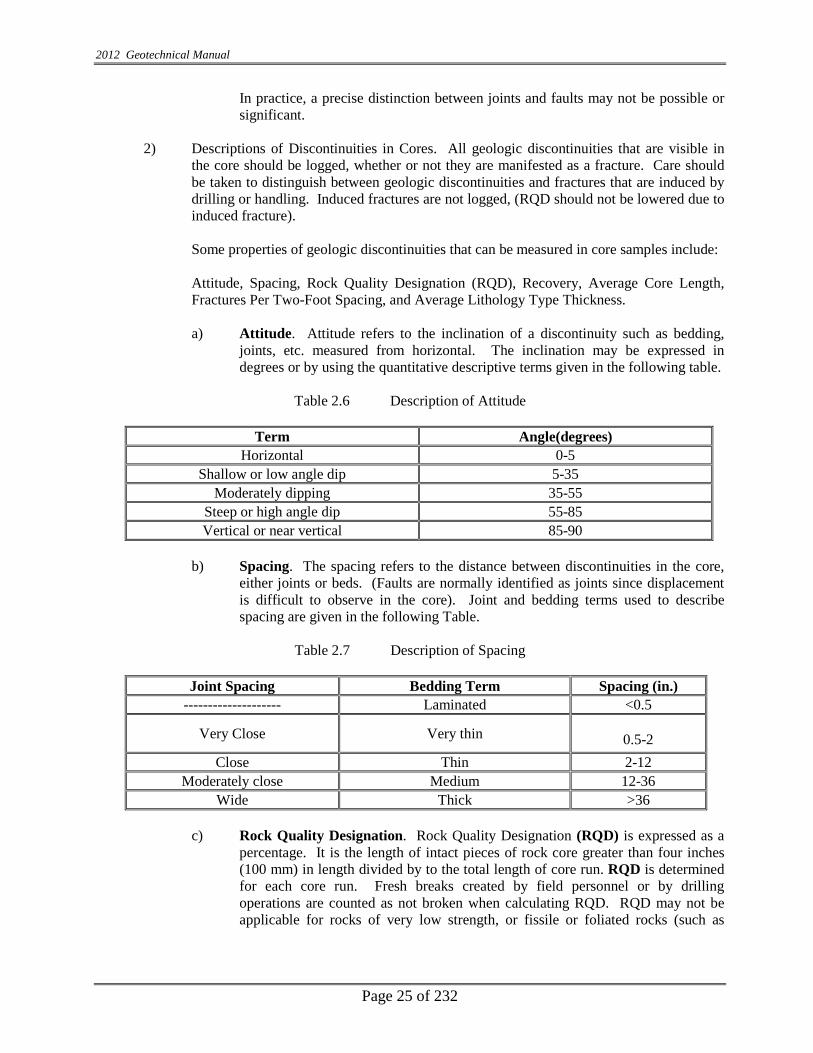
2012 Geotechnical Manual
Page 25 of 232
In practice, a precise distinction between joints and faults may not be possible or significant.
2) Descriptions of Discontinuities in Cores. All geologic discontinuities that are visible in the core should be logged, whether or not they are manifested as a fracture. Care should be taken to distinguish between geologic discontinuities and fractures that are induced by drilling or handling. Induced fractures are not logged, (RQD should not be lowered due to induced fracture). Some properties of geologic discontinuities that can be measured in core samples include: Attitude, Spacing, Rock Quality Designation (RQD), Recovery, Average Core Length, Fractures Per Two-Foot Spacing, and Average Lithology Type Thickness.
a) Attitude. Attitude refers to the inclination of a discontinuity such as bedding,
joints, etc. measured from horizontal. The inclination may be expressed in degrees or by using the quantitative descriptive terms given in the following table.
Table 2.6 Description of Attitude
Term Angle(degrees)
Horizontal 0-5 Shallow or low angle dip 5-35
Moderately dipping 35-55 Steep or high angle dip 55-85 Vertical or near vertical 85-90
b) Spacing. The spacing refers to the distance between discontinuities in the core,
either joints or beds. (Faults are normally identified as joints since displacement is difficult to observe in the core). Joint and bedding terms used to describe spacing are given in the following Table.
Table 2.7 Description of Spacing
Joint Spacing Bedding Term Spacing (in.)
-------------------- Laminated <0.5
Very Close Very thin 0.5-2 Close Thin 2-12
Moderately close Medium 12-36 Wide Thick >36
c) Rock Quality Designation. Rock Quality Designation (RQD) is expressed as a
percentage. It is the length of intact pieces of rock core greater than four inches (100 mm) in length divided by to the total length of core run. RQD is determined for each core run. Fresh breaks created by field personnel or by drilling operations are counted as not broken when calculating RQD. RQD may not be applicable for rocks of very low strength, or fissile or foliated rocks (such as

2012 Geotechnical Manual
Page 26 of 232
shales), as they may break apart easily making identification of natural verses mechanical breaks nearly impossible.
RQD=Run CoreRock ofLength Total
GreaterOr )(4" 100mm Pieces ofLength Total
RQD has been related to the overall engineering quality of the rock with higher RQD values indicating more intact and better performing rock as shown in the following Table.
d) Relationship between RQD (Rock Quality Designation) and Rock Quality (from
Deere, 1969).
Table 2.8 Description of RQD
RQD% Rock Quality 0 - 25% Very Poor 25-50% Poor 50-75% Fair 75-90% Good 90-100% Excellent
e) Core recovery, (REC) is expressed in a percentage. It is the length of rock core
retrieved from the core hole divided by the total length of the core run, expressed as a percentage. This is often an indicator of rock quality, with higher percentages suggesting a more intact rock mass.
f) Average Core Piece Length. Average Core Piece (>100 mm) Length (ACPL) is
the average measurement of the length of core segments that are greater than four inches (100 mm) long. This value (expressed in mm) is a further indication of the relative spacing of the discontinuities, and calculated for any specified interval.
g) Fractures Per Two-Foot Interval. Fractures per two-foot interval refer to the
total number of fractures, excluding those induced by drilling or handling, which occur in a two-foot interval of core. Intervals with more than ten discontinuities are recorded as >10. Zones within a two-foot interval that have more fractures than can be readily measured are designated as “rubble”.
h) Average Lithology Type Thickness (ALTT) is useful in describing rock core samples with alternating thin beds of differing lithology, such as Limestone and Shale, as in the Ordovician in Southeastern Indiana. The thicknesses of similar rock type units are averaged over any specified chosen interval. A note describing maximum length of a one-piece length of core for each type of rock can also be descriptive of strength.

2012 Geotechnical Manual
Page 27 of 232
3) Descriptions of Discontinuities in Outcrops. In some cases it may be desirable to further investigate the rock mass characteristics of a rock body. This will normally be accomplished by geologists from the Geotechnical Section. Additional descriptions might include orientation of discontinuities (strike and dip) and continuity (lateral extent of a discontinuity). These types of assessments are important when designing items such as the angle of rock backslope, tunnel support, bearing capacity near rock cuts, or excavation methods.
2.24 RELATIVE ROCK HARDNESS
Rock hardness is a measure of rock strength, and is controlled by many factors including degree of induration, cementation, crystal bonding, and/or degree of weathering. Rock hardness may be estimated through manual tests on core samples or outcrops to yield a “field” identification (described in the following Table) which can be refined through further laboratory testing. The relative hardness of rock should be determined for each rock core sample or outcrop. Multiple designations would be required for variable rock conditions, such as lithological changes or weathering.
Table 2.9 Field Identification of Rock
Term Field Identification
Extremely Soft Loose sand to soft core, crumbles or falls apart (very friable) upon removal from core barrel/split tube, or under slight pressure; (Un-cemented Sandstone).
Very Soft Can be indented by thumbnail. May be moldable or friable with finger pressure. In outcrop, can be excavated readily with point of geology pick. Sandstone can be deformed or crushed with fingers.
Soft
Can be scratched with fingernail. Can be peeled with a pocket knife. Crumbles under firm blows with geology hammer/pick. Sandstone cannot be deformed with finger, but grains can be rubbed from surface and small pieces can be crushed between fingers with some difficulty.
Hard Can be scratched by knife or geology pick only with difficulty. Several hard hammer blows required to fracture specimen.
Very Hard Cannot be scratched by knife or geology pick. Specimen requires many blows of hammer to fracture or chip. Hammer rebounds after impact.
2.25 STRENGTH TESTS
When quantitative values for rock strength are desired, strength tests, such as Unconfined Compressive Strength, Schmidt Hammer, or Point Load Tests can be performed. See the Geotech Lab Unit for assistance.
2.26 SAMPLE DESCRIPTION
It is important to give as complete a description as soon as possible of the appearance and occurrence of rock materials in the field, for use in preliminary engineering and design. The following is a recommended list for the description of rock as viewed in an outcrop in the field, or in the lab as core samples:

2012 Geotechnical Manual
Page 28 of 232
Lithology (with modifying mineral description, if possible); Weathering; Discontinuities (frequency and orientation of joint faults and beds); Color; Grain Size and/or texture; Formation, member, or unit name; and Occurrence (extent of outcrop or depth below surface).
An example of description of a rock outcrop would be: Limestone, microcrystalline, with fossils, slightly weathered, thin to medium bedded, many high-angle and low-angle joints. Joint spacing averages 300 mm apart. Gray todark gray (St. Louis Formation). Outcrops between Station 150 to Station 160, approximately 10 feet above shoulder. Habitual use of such a list will help in ensuring completeness and consistency of rock description and aid in comparability of descriptions prepared by different field personnel.

2012 Geotechnical Manual
Page 29 of 232
Table 2.10 Rock Unit Names
ERA, PERIOD, SYSTEM, EPOCH, AND SERIES NAMES USED IN INDIANA
Era Period and System Epoch and Series
CENOZOIC
Quaternary Pleistocene
Tertiary Pliocene Oligocene* Miocene Eocene*
Paleocene*
MEZOZOIC
Cretaceous*
Jurassic*
Triassic*
PALE
OZO
IC
Permian*
Pennsylvanian Monogahelan* Conemaughian
Alleghenian Pottsvillian
Missississippian Chesterian
Valmeyeran Kinderhookian
Devonian Senecan and Chautauquan
Erian
Ulsterian Helderbergian*
Silurian Cayugan Niagran
Alexandrian
Ordovician Cincinnatian
Champlainian Canadian
Cambrian St. Croixan Albertan* Taconian*
PRECAMABRIAN *No deposits known in Indiana revised 5/7/98

2012 Geotechnical Manual
Page 30 of 232
Fig. 2.2 Time Scale of Formation of Various Kinds of Rocks

2012 Geotechnical Manual
Page 31 of 232
CHAPTER THREE
GEOTECHNICAL INVESTIGATION AND SAMPLING
3.0 GENERAL All Geotechnical work performed by an approved consultant for the State of Indiana or Local Agencies, such as any Indiana local municipalities and/or county government involving the use of State or Federal funds, shall meet the requirements as described herein. All the dimensions of the equipment shall meet the requirements of AASHTO, ASTM and/or Indiana Test Methods (ITM) s unless otherwise specified herein. All work performed by the licensed Geotechnical Engineer for state and local agencies under these requirements shall consist of making a complete foundation investigation for the adequate design and construction of bridges, roadways and any other associated structures. A complete foundation investigation shall consist of an adequate program of field sampling, laboratory testing and engineering analysis and evaluation, with the results presented in report form. The investigation shall be performed in compliance with the procedures outlined in this document and generally accepted principles of sound engineering practice. The investigation shall be under the general supervision and subject to the approval of the Manager, Office of Geotechnical Services of the Indiana Department of Transportation. Unless otherwise subsequently noted, later references to as approved or directed will imply as approved or directed by the INDOT Manager Office of Geotechnical Engineering.
3.1 GEOTECHNICAL SURVEY The geotechnical survey is defined as the investigation of subsurface conditions along new or existing highway alignments, as required for the adequate design and construction of bridges, roads and other necessary structures. This investigation may be preliminary such as a corridor study or it may be more specific such as the more frequently performed geotechnical surveys of roads, bridges, retaining structures, landslides, etc. The survey details will depend upon the requirements of the individual project, except for resurfacing existing pavement and minor maintenance; a Geotechnical Survey will be performed on all projects.
3.2 PURPOSE OF GEOTECHNICAL SURVEY The purpose of the geotechnical survey is to identify the existing conditions of the in-situ soils, rock types and ground water in respect to the project requirements. It will also include the chemical and physical properties of the soils and rock so as to better enable the engineers to design the most uniform, stable and cost-effective road or bridge foundations. The survey will also be used to locate construction material for building embankments along roadways.
3.3 AVAILABLE INFORMATION AND TYPES OF SURVEYS
3.3.1 REVIEW OF AVAILABLE INFORMATION
Indiana is exceptionally fortunate to have State organizations which have published geological, agricultural, and water surveys for many years. These publications provide a wealth of information for nearly every part of the State. Therefore, prior to initiating the field work for any project, a review of this literature, as well as previous studies done for and by INDOT, should be undertaken. This literature survey should be followed by an examination of any available boring logs and well drilling records, as well as any other available information.
2012 Geotechnical Manual
Page 32 of 232
Also, this information gathering could include a review of aerial photography; USDA/SCS reports; topographic, pedologic, bedrock surface, geologic, INDOT Data Bank, and quaternary deposits maps; and other pertinent studies which have been completed for and near the project site.
3.3.2 OFFICE STUDIES
The initial steps for conducting a geotechnical survey are done in the office, prior to going into the field. First, the project is classified e.g. as an overlay, rubbilization, reconstruction, new construction, bridge rehabilitation, bridge replacement, or landslide, etc. This will provide an indication of the extent and complexity of the required geotechnical report. A review of currently available information needs to be performed.
3.3.3 PRELIMINARY PLANS
The proposed route and grade are a part of the preliminary plans. By review of these plans and the available literature, a Geotechnical Engineer can identify many of the conditions that could potentially cause problems. These may include the extent of fill, cut, peat/marl deposits, landslides, sinkholes, and abandoned mines, etc.
3.3.4 MAPS
Any available maps will be useful in determining the extent to which construction will influence or be influenced by the physical site conditions. Listed below are types of maps that may prove useful.
1. Quaternary Geologic Map of Indiana. 2. 1o x 2o Regional Geologic Maps. 3. 7 1/2 Minute Topo Quadrangle Maps. 4. Topograph of the Bedrock Surface. 5. Thickness of Unconsolidated Deposits. 6. Soil Conservative Service County Soil Survey Map. 7. JTRP A-P Soil Survey. 8. Map for Seismic Design Specification. 9. Area Maps For Mines
These maps can be used as guides in planning the Geotechnical Investigation and defining areas of concern for the site reconnaissance. Additional maps of different types are available through the Geological Survey in Bloomington, Indiana.
3.3.5 PREVIOUS WORK
Studies and construction plans completed for the existing or nearby projects can be useful in identifying the problem areas. In particular, previous investigations and construction records that give a history of the roadway and bridge are useful in planning the investigation.
The INDOT Geotechnical Section maintains many geotechnical reports from previous projects. This includes preliminary plans, boring logs, test results, field observations, and correspondence relating to the project. Because of limited space, occasionally older files are eliminated, so not all projects are available.

2012 Geotechnical Manual
Page 33 of 232
Proper use of previous geotechnical data can sometimes reduce or even eliminate geotechnical work in some project areas. It can help define soil types and pinpoint the areas of typical geotechnical problems even before the first on-site field investigation.
3.3.6 AERIAL PHOTOGRAPHY
The first step in any site investigation should be an examination of the area geography. Easy and quick resources for investigating are the various interactive map sites on the internet. Some examples include, but not limited to the following sites: http://maps.google.com; http://maps.yahoo.com; http://earth.goggle.com/ and so on. Internet maps are more current than the photographs provided by the USD/SCS in their county soil maps, and the internet maps are set up to be maneuverable to more closely observe features of the site which are pertinent to the geotechnical investigation.
3.3.7 PEDOLOGICAL MAPS County agricultural reports contain maps showing the location and extent of the various soil types that occur in that county. The engineering characteristics of individual soil types are described in summary form in many of these reports. These maps generally only extend to a maximum depth of 6 ft. (2 m).
3.3.8 GEOLOGICAL MAPS
A variety of maps and reports on the geology of most of the State are available from the Indiana State Geological Survey. A thorough search of the site’s geologic data may provide an idea of the variety of deposits which may be encountered during the boring program. In addition, a review of the oil and gas maps, strip mine area maps, and coal reserve maps may also give an indication of additional areas of concern.
3.3.9 MAINTENANCE INPUT
It is important to get past performance, history, frequency and type of rehabilitation from the maintenance engineer. This information can be found during the preliminary field check. Sometimes it is noteworthy to ask questions about the maintenance history from the local INDOT or county transportation workers to obtain more details about past problems.
3.3.10 ENVIRONMENTAL CONCERNS
Any available environmental information which could impact the Geotechnical design, should be reviewed. The Pre-Engineering and Environment Division of INDOT performs environmental assessment reports on all state projects. Included is the possible presence of old underground storage tanks, hazardous or toxic spills, etc.

2012 Geotechnical Manual
Page 34 of 232
3.3.11 FIELD RECONNAISSANCE The Geotechnical Engineer shall attend the preliminary field check and establish the boring locations, rig type requirements/accessibility and record any existing problems such as pavement distresses, slope failures or any other problems within the project limits. During the field check, the Engineer should inquire about any details related to bridges, culverts, retaining structures and time restraints as well as local ordinances about any construction activities. Environmental concerns should be reviewed at this time also. In field checks, the individual should prepare a memorandum consisting of the scope of the work and minutes of meetings and should be submitted to the INDOT Geotechnical Section.
3.4 PERFORMANCE OF FIELD WORK ON PRIVATE PROPERTY
3.4.1 ENTRY PERMISSION
When the State of Indiana’s employees and representatives must enter and work on private property, they are required to follow Indiana Code 8-23-7-26-,27,28, which took effect on July 1st, 2008. The usual information about the project and its impact on the property owner/tenant should start the letter, along with an explanation of the type work, a timetable to expect entry and an estimate how many days the work will take should be given, but a notice of survey (NOS) letter is required by law to include the following:
1. Include both the occupant and the recorded owner of the property in the notification process.
2. A description of the aggrieved party’s right to compensation for damages. 3. The procedure the aggrieved party must follow to obtain the compensation. 4. The name, address and telephone number of an individual or office where property owners
may direct questions about the investigation. (This would be the geotechnical consultant’s information.)
5. The name, address and telephone number of an individual or office where property owners questions about the rights and procedures for damage compensation may be directed. (This would be the project area’s INDOT District Office, to the attention of the district’s Real Estate Manager.)
6. A copy of the Indiana Code 8-23-7-26, 27, 28 should be included with the letter. This will assist property owners with immediate answers to many of their questions.
After the field work is finished, Form IC-662 is to be immediately completed for crop damages. (Property damages are handled by the district in a different manner and are not claimed on Form IC-662.) All Form IC-662 claims are to be promptly directed to the appropriate District Real Estate Manager since a timetable of sixty (60) days for reimbursement of an agreed upon compensation is established in the code.
2012 Geotechnical Manual
Page 35 of 232
3.4.2 CROP DAMAGE CLAIMS INCURRED ON PRIVATE PROPERTY Crop damage claims are to e reported on Indiana Form IC 662. The forms should be filled out completely and accurately, with a sketch (length and width) of the damaged crop areas, the location where the damages occurred on the property in reference to a known point, and type crop planted. Acreage can be easily converted once the square footage of damages is determined by using the following website: http://www.metric-conversions.org/area/square-feet-to-acres.htm After the forms are filled out, send immediately to the project location’s District Real Estate Manager for review and payment. An example of a completed form as well as a blank IC 662 is in the Appendix.
It is also the sole responsibility of INDOT and the Consultant Geotechnical Engineer, acting as a representative of the Indiana Department of Transportation or Local Public Agency, to compensate the property owners for any damage incurred to their property because of the Geotechnical Investigation. Damage compensation including crop damage should be handled as outlined in the aforementioned Indiana Code, by completing Indiana form I. C. 662 as accurately as possible then transmitting the information to the INDOT District Development office of the project area. Compensation of the damages will be handled by the district personnel. If the property owner is not satisfied with the compensation as determined by INDOT, the County Agricultural Agent will be asked to assist. (Appendix 3.1, I.C. 662.) Compensation for the damages of local agency projects will be handled by the Design consultant and local government.
3.5 EQUIPMENT
The equipment used shall be hand or power operated drilling, and/or driving equipment or other tools considered suitable or necessary for determination of the limit and conditions of the various soil strata and for obtaining samples for field examination and classification, and lab analysis. All drilling rigs which take splitspoon samples must now be equipped with yearly calibrated automatic hammers, and calibration records for each rig’s hammer must be available for INDOT inspection when requested. Catheads used for sample taking are no longer an INDOT option due to the inaccuracy of the method. Pile driving analyzers are the method commonly used for calibration of drill hammers. Only approved equipment shall be mobilized to the project sites as determined by a pre-drilling field check. If it is deemed necessary to change or add rigs during the process of drilling the project due to unforeseen circumstances at the site, the mobilization of the additional rig must be approved by the Office of Geotechnical Engineering prior to the move if additional payment for Mobilization is to be requested. Power rigs are of the following four (4) types are generally used;

2012 Geotechnical Manual
Page 36 of 232
1) Truck-Mounted Rig: This is a drill rig mounted on a truck chassis. Unless the truck is four-wheel drive, the rig is usually limited to flat, dry, open areas where mobility is easier. Less labor intensive than a skid rig, the truck mounted rig usually has leveling jacks and hydraulic cables on the rig body to assist the drillers with the physical lifting associated with drilling operations.
2) Skid Rig: This is a power rig mounted on runners, like a sled. It is used in rough terrain where space is limited and where it is difficult, if not next to impossible, to access the site with a carrier-mounted rig. The rig is advanced across the terrain and through obstacles by means of a winch and cable system, which is used to pull the rig from one area to another. This rig has less hydraulics and is more labor intensive for drillers.
3) Swamp Buggy-ATV: This is a drill mounted on a rubber tired carrier or track carrier, which can be driven off-road in areas where a truck rig cannot go and a small skid is not required or is inadequate. The versatility of the “ATV” rig is undeniable since they can access almost all sites. The only drawback is that an ATV requires a trailer to transport it from project site to project site. Unlike a truck, it cannot be driven on public roads.
4) CPT Rig: The equipment may be mounted on a conventional drilling rig or it may be a dedicated CPT truck with Penetrometer Cone, drill rods, electrical cable and data acquisition system.
3.6 UTILITIES
Buried utilities must be located prior to the start of all geotechnical investigations. Most Indiana companies subscribe to the “Holey-Moley” network at 1-800-382-5544. Companies which are not members, in most cases municipal utilities, need to be contacted individually. Failure to contact these companies could result in injury or death to geotechnical drill crew members and the public and/or a loss of utility services. Before contacting the utility companies to locate their buried lines, it is helpful if all soil test boring locations are marked in a distinctive manner (laths, flags, paint, etc.) in order to expedite the process. If the roadwork involves extensive roadwork over several blocks or miles, it is recommended that a meeting be planned, onsite, with the utilities locators so that no boring locations are missed. If a meeting is not feasible, maps of the project with the soil test locations clearly marked (to be given to the locators) are an excellent alternative. Overhead utilities, although in plain sight, are sometimes forgotten. Drilling crews with high mast rigs should work within the guidelines established by the affected utilities and it is recommended that “insulators” or “boots” be placed on the wires to protect the workers. If it is imperative that data be obtained from directly under power lines, then an alternative to drilling with a high mast rig must be used such as a tripod, hand auger, pit, etc. Consider all overhead lines to be alive and dangerous. Older, urbanized areas can have abandoned utility lines or tanks, which could be encountered during drilling. Getting information about these lines prior to drilling from the utilities and street departments could help prevent “anxious” moments if one is accidentally hit. All utility hits should be treated as active lines, and follow the safety guidelines set down for such an emergency, until the utility company can confirm the abandoned line as such.

2012 Geotechnical Manual
Page 37 of 232
The American Right-of-Way Association has established color codes to surface mark buried utilities. These color codes are in compliance with the Occupational Safety and Health Acts (OSHA) standards.
Table 3.1 Color Code Identification
Orange Telephone Red Electric
Yellow Gas Blue Water
Green Sanitary Sewer White New Construction
INDOT commonly uses pink and/or white markers for locations where geotechnical drilling is to be done.
3.7 DRILLING SAFETY
3.7.1 TRAINING
Drilling safety begins with an introductory safety course for all new drillers, inspectors, engineers and others who are in the field with the drill rig operators. The “Drilling Safety Guide” published by the International Drilling Federation and the “Drilling Safety” film produced by Mobile Drill Co., and ATC Associates (formerly ATEC) are good examples of the industry safety guidelines.
The drill rig operator is the designated safety supervisor and is expected to enforce safety rules at all times around the drilling site. His duties include the enforcement of the use of proper personal protection equipment, proper maintenance of tools and general housekeeping on the site and in the vehicles. Also, he is to perform an inspection of the rig for structural flaws, damaged gauges, fluid leaks, properly working warning devices and shut-down switches on a regular basis. He is to maintain a properly working fire extinguisher and first-aid kit in each vehicle with all crew members trained to use them.
3.7.2 PERSONAL SAFETY GEAR
Every person around the drilling operations is required to use personal protection equipment, which includes, but is not necessarily limited to, a safety hardhat, safety shoes and hearing protection. Those working in close proximity to the augers are required to have no loose-fitting clothing with straps, drawstrings, belts, loose ends or otherwise which might become entangles in the rotating augers. Rings and other types of jewelry should not be worn at any time and long, loose hair should be pulled back and secured.

2012 Geotechnical Manual
Page 38 of 232
In cases where there is known contamination i.e., (chemical, biological and radioactive) and special protection is required, it becomes the responsibility of each consultant to provide their drilling crew with the appropriate equipment and clothing for the project.
3.7.3 SITE MAINTENANCE
The drilling supervisor is responsible for “good housekeeping” on the drill rig and around the drilling site. There must be suitable storage for all tools, materials and supplies to avoid placing them in areas where they cannot be safely handled or secured. Heavy rods, pipe, casings, augers, cables and other drilling tools should be stored in an orderly fashion to prevent movement when not in use. Work areas should be free of debris and obstructions and hazardous substances such as grease, oil or ice which could cause surfaces to become slick and hazardous.
When leaving the testing site, it is everyone’s responsibility to make sure all holes have been backfilled properly, dirt mounds scattered and sod replaced if necessary. All debris should be removed and the drill site returned to the condition it that was in before drilling operations began. If possible, a follow-up inspection to inspect and correct any settlement of the test holes should be done.
3.8 TRAFFIC CONTROL
This work shall consist of providing traffic control services in accordance with the INDOT Worksite Traffic Control Manual, when traffic flow must be restricted in order to conduct drilling or coring operations.
3.9 NATURAL AND MANMADE HAZARDS
3.9.2 RIVERS AND STREAMS Drilling on a river requires a barge set-up if it is not possible to access through the existing bridge deck. The drilling needs to be done at a time when flash floods are not likely and should never be done in flood conditions. Drillers should be equipped with life vests or personal floatation devices while working on the water and, because icy conditions could develop quickly, it is not advisable to work on a barge in the winter cold.
Barge set-up is a payable item and consultants are expected to provide a safe working environment for their crew by having dependable floatation devices for them.
3.9.3 UTILITY LINES
Always have buried utility lines located before drilling at the “Holey Moley” number 1-800-382-5544. See section 3.7 for more information.

2012 Geotechnical Manual
Page 39 of 232
3.9.4 TOXIC OR HAZARDOUS AREAS
Most projects have an environmental assessment prior to any geotechnical survey which identifies hazardous areas. site previously thought to be “clean” is found to be hazardous, then it
3.9.5 NATURAL GAS POCKETS In Indiana, naturally occurring gas pockets have been opened up several times by standard geotechnical drilling methods over the years. Due to the volatility of the trapped gas, which can escape at high pressures, immediate action must be taken to make the situation as safe as possible for all involved at the drill site as well as the public safety concerns. Actions to be taken if a trapped natural gas pocket (not piped gas) is opened during drilling operations:
1. Immediately shutdown of all equipment being used on order to prevent electrical
sparks from igniting the gas and all on-site workers move away from the equipment.
2. All traffic must be stopped and or rerouted away from the scene by the local sub-district personnel traffic control crew. They should also call their Sub-District Manager to contact local emergency personnel about the situation.
3. From a safe distance, call the Geotechnical Drilling Manager and/or Engineer (317-610-7251) about the situation.
4. The Geotechnical Drilling Manager and/or Engineer will contact the Indiana Department of Natural Resources Division of Oil and Gas Assistant Director (office: 317-232-4055, directly: 317-232-6961) and IDNR will then contact their field personnel about the situation and send someone to the site to assist.
5. As per directions from the IDNR personnel on site, observe the pressure and amount of gas being expelled and determine when the situation is safe enough to close up and abandon the hole.
3.10 GEOTECHNICAL SAMPLING REQUIREMENTS For geotechnical analysis in fill or cut areas, Shelby tube samples and split-spoon samples should be taken, depending on the soil type. Generally, in sandy soils, split-spoon samples are preferred. In cohesive silty and clayey soils, the Shelby tube samples are more reliable. Other relatively undisturbed sampling systems, may also be used at the discretion of the MOGE, (Manager Office of Geotechnical Engineering). If these systems are used, the wall thickness of the tubes should result in an area ratio (Ar) which does not exceed 30%. The area ratio is defined as the ratio of the volume of soil displacement, to the volume of the collected sample, and it is expressed as:

2012 Geotechnical Manual
Page 40 of 232
100(%) 2
022
×−
=I
Ir
DDDA
Where: Ar = Area ratio D0= Outside diameter of tube DI = Inside diameter of cutting edge An area ratio of 100% means that the in situ soil was displaced by a volume equal to that of the collected sample. Well-designed tubes have an Ar less than 10%.
3.11 STANDARD SAMPLING - DISTURBED
3.11.1 SPLIT SPOON SAMPLES
Generally, all borings requiring samples will be taken with a split-spoon sampler to obtain the data for the Standard Penetration Test, or SPT. The samples are taken at 2.5 feet (0.75 m) intervals for the upper 10 feet (3.0 m) and a 5 feet (1.5 m) interval thereafter unless otherwise requested.
The sampler shall be the standard 2 inch (51 mm) O.D. and 1 ½ inch (38 mm) I.D., driven with a 140 lb. (63.5 kg) hammer, dropped 30 inch (760 mm). The number of “blows” required of the hammer to drive the split spoon 1 ½ feet (450 mm), in 6 inch (150 mm) intervals, shall be recorded. The penetration resistance, called the N-value, shall be defined in AASHTO T-206 Standards and shall be the total of the last two intervals, or 1 foot (300 mm), of the 1 ½ feet (450 mm) drive.
Two jar samples, each approximately 6 inch (150 mm) long shall be obtained from each split spoon sample for laboratory examination and/or testing. Keeping the samples as intact as possible, they are to be seated in clean glass jars to prevent loss of moisture, properly marked with the project number, boring number, sample number, blow count and field identification number. As soon as possible after drilling, the samples should be delivered to the laboratory for tests.
3.11.2 BAG SAMPLES
1) CBR (California Bearing Ratio)/Mr (Resilient Modulus)
A CBR/Mr bag sample shall be obtained for each project, usually from the most critical soil found during the drilling. The critical soil will be determined from the predominant soil source, but if the critical soil does not exist in sufficient quantities to obtain the amount required for a minimum bag sample, 250 lbs, then engineering judgment shall be used to select another critical soil.
2012 Geotechnical Manual
Page 41 of 232
Additional CBR /Mr tests should be performed for relatively large projects where significant differences in soil types occurs for proposed subgrade. Engineering judgment should be used here also. It is easy to obtain the CBR/Mr sample from auger cuttings or shoveled from a pit. Care should be taken to remove any topsoil, grass, rocks or plant debris from the sample before placing in the bag. Two (2) jar samples shall be included in the sample to be tested for in-situ moisture. All bags shall be properly tagged, inside and out, with tags showing the project number, road, sample number, station and offset, date, and field identification number and delivered to the lab in a timely manner. Soil classification tests are also assigned for each CBR bag sample.
2) Moisture and Density Test
A small bag sample, 24 lbs (11.0kg), is required of all cohesive type soils found during a subgrade investigation. The sample shall be taken from directly under the pavement/subbase strata, from the auger cuttings. A jar sample for moisture testing is not necessary if a splitspoon sample was taken.
All bags should be properly tagged on the outside as with the normal size CBR sample and delivered to the lab in a timely manner.
3.11.3 PITS
In areas such as gullies, ravines or in streambeds, where it is not feasible to place a drill rig and information from a hand auger is inadequate, pits are dug to establish bedrock elevations and overburden depths. Usually, a series of 10 sq. feet (1 m2) pits, in an acceptable pattern as per the requirements of the project, is dug by hand to confirm expected data. This method of data collection is limited to sites where shallow bedrock is known or expected, usually within a 3 feet (1 m) depth. Usually, no samples are taken although a CBR sample could be obtained; however, profile jar for grain size analysis and moisture tests as needed.
3.11.4 HAND AUGERS
Hand Augers are limited to soft soils and soils with cohesion and are preformed in areas where standard penetration tests are not possible or unnecessary. They are used to obtain a profile of the existing strata, sometimes with samples.
There are five types of hand augers; 1) the sample hand auger is a minimum of 1 ½ inch (38 mm) diameter, 2) the 1 inch (25 mm) retraction piston sampler, 3) a peat sampler, 4) hand guide power hand auger and 5) a 3 inch (76 mm) diameter post hole type auger. Hand augers shall not exceed 6 inch (150 mm) per increment of advancement, and are performed in accordance with AASHTO T-203. If samples are obtained, they shall be placed in jars, sealed and labeled appropriately.
2012 Geotechnical Manual
Page 42 of 232
3.12 UNDISTURBED SAMPLES – SHELBY TUBES Undisturbed samples, if required by the engineer, shall be obtained by pressing a thin-walled tube into the soil with a slow, continuous push. The Shelby Tube shall measure 2 to 3 inches O.D. and the length shall be as recommended in Table 1 of AASHTO T-207 or longer to avoid overfilling of the tube during sampling. The standard lengths for INDOT are: 30 to 36 inches. A recovery of 50% or greater is required or 9 inch unless otherwise approved by the Manager, Office of Geotechnical Services. Immediately upon retrieval, the tubes are to be trimmed and cleaned of excess soil on the ends, sealed with approved air-tight expanders and/or sealing wax on both ends. A suitable filler shall be added to the void at the top of the Shelby Tube to prevent movement of the sample within the tube. Both ends shall be covered with plastic caps, then tape should be applied in such a manner as to seal the open boltholes and the lip of the cap. Samples shall be kept in a vertical position with the top up during transporting and storage. Samples shall not be jarred or shaken, and shall always be protected from temperature extremes, especially freezing. Each tube shall be properly tagged inside and out with all the pertinent information; project and designation number, road, boring, station and offset, line, depths, recovery percentage and date. It shall be delivered promptly to the laboratory for testing.
3.13 ROCK CORES This involves using a drill rig to core through hard rock, which cannot be augured through. Core barrels, double or triple-tucked, with diamond core bits, of "NX", "NWG", or "NWPAM" (2 inch) sizes are suggested to obtain an approximate core size of 2 inches. The core barrel shall be 5 feet long with an inside diameter of 2 inches to obtain the minimum size core, unless otherwise approved by the Chief Geotechnical Engineer. Longer barrels can be used, but the maximum allowable run is 5 feet. If shale or any other non-durable sedimentary rocks are encountered, the core samples shall be wrapped tightly in a moisture-proof wrapping such as aluminum foil or plastic wrap to prevent drying of samples.
3.14 PAVEMENT CORES/SUBBASE
Pavement cores shall be obtained from existing pavement when an analysis or test of the core is requested by the Pavement Design Engineer. This core shall be 8 inches (200 mm) to 9 inches (250 mm) in size and properly labeled and taken to the lab. If testing of the core is not required, then other methods of drilling through the pavement is acceptable. A detailed log with full description of type material and thicknesses should be written out for each pavement core.
Subbase sampling usually follows the pavement core. Once the pavement core has been extracted, the boring shall be extended through the subbase to the subgrade and all information about the strata are logged, however no sample will be taken for testing.

2012 Geotechnical Manual
Page 43 of 232
3.15 LOCATIONS AND DEPTHS OF BORINGS Locations and depths of soil borings are very important for the Geotechnical investigation of the proposed structure. It should provide the maximum possible information about the subsurface conditions for the design of the structure. The location and the depths of soil borings depend upon the existing topography, type of the structure as well as shape, size and anticipated loads of the structure. The following are the guidelines for soil boring locations and depths for various kinds of structures. For detailed guidelines AASHTO section10.4.2 as well as current FHWA and NHI manuals should be considered.
3.16 BRIDGE STRUCTURES
3.16.1 LOCATION OF BORINGS
The INDOT Division of Design or the Design consultant shall furnish plans of structure for which borings are to be made. Generally, the plans shall consist of road plan and profile sheets, a situation plan showing the location of substructure elements cross-sections of the structures approaches. The plan and profile sheet will have included on them the maximum high water elevation and the stream bed elevation. In general, there shall be a boring made near one end of each pier and end bent with the borings alternating right and left of the center line of the structures. Twin structures shall be considered as separate structures. Additional borings shall be required as described in the following sections, or as directed by the Engineer. In the case of skewed structures, the borings should be located at the extreme end of the end bents to better determine any subsurface variation at the maximum end limits of such proposed structure.
3.16.2 DEPTH OF BORINGS
The following general guidelines have been established for a working load up to 70 tons on a single pile. The first boring performed should be the one for an interior pier and shall be drilled to a minimum depth of 90 feet below ground elevation, unless bedrock is encountered at a shallower depth. The remaining borings shall generally penetrate to an approximate depth of 70 feet below the ground elevation. However, if higher loading piles are proposed, deeper borings shall be performed. To determine the depths, Engineering judgment shall be used based on the loading condition. The deeper boring shall always be drilled first at each structure, and should be located so as to get the most information, such as at the lowest elevation, or in flow line.
In the case of stream crossings, the boring depth shall penetrate a minimum of 15 feet below the maximum actual scour depth or to a depth below the maximum actual scour depth sufficient to carry the pile loads with the scourable overburden materials removed, which ever is greater. The latter depth shall extend 5 feet below the anticipated pile tip elevations. Engineering judgment shall be required to establish the pile tip elevations required to carry the pile loads and should be handled on an individual basis for each structure. Specific guidelines for the final depth of boring in soil and in bedrock are outlined below.

2012 Geotechnical Manual
Page 44 of 232
3.16.3 BORINGS IN SOIL
Borings in any soil shall penetrate a minimum of 20 feet continuous into material having a standard penetration value of fifteen (15) or greater. If this minimum penetration of fifteen (15) or more material has not been obtained at proposed boring depth, the boring shall be extended until this requirement is met. Borings shall be extended such that the soils encountered within the borings will be capable of supporting the anticipated loads. The depth of the boring shall extend a minimum of 5 feet below the anticipated tip elevation. When ground water is encountered, water should be added to the hole to maintain the water level in the hole at, or above, the ground water level, to aid in avoiding a quick condition when granular soils are encountered. This precaution will keep the sand from coming up in to the casing. For loose to medium dense sand below the water table, the bore hole may need to be stabilized with drilling fluid to prevent heave of the sand up into the casing. The ball check valve in the split-spoon sampler should not be removed, and washing through the spoon will not be permitted.
3.16.4 BORING THRUOGH ROCK
When rock is encountered in the boring, rock coring will be required in each boring. Rock coring should not begin until auger refusal is obtained. Auger refusal shall be defined as no auger penetration under 900 psi of auger-feed down pressure for a period not less than 4 minutes. Rock coring should not begin or end in weathered shale, weathered limestone, etc., unless absolutely necessary and coring and sampling shall not be terminated in coal seams or voids. Recovery and RQD (Rock Quality Designation) shall be calculated and recorded before transporting the core sample from the boring locations. The criteria for minimum RQD might be lowered for some areas, such as in the Dearborn upland Physiographic Region, or fissile shale formations in which recovery rates greater than 90% are achieved. The following series of guidelines are presented to enable the geologist, geotechnical engineer or others to prepare a subsurface drilling and coring program. However engineering judgment should also be used to determine the subsurface profile based on known or mapped geology, and regional geotechnical experience which could include the knowledge of karst areas, mines, rock elevation extremes and boulder rich glacial sluice ways to name a few. If rock is encountered in the course of conducting borings for a structure a minimum core of 10 feet into rock will be required at each substructure of the structure with a minimum recovery of 75% and minimum RQD of 50%. If these values are not achieved an additional 5 feet of coring shall be completed. If the project is in an area in which it is known that a geologic conditions will not allow these criteria to be met engineering judgment must be applied. A sounding shall be performed at the opposite end from the boring made for each pier and/or each bent. These soundings shall be terminated in the
2012 Geotechnical Manual
Page 45 of 232
sound rock after achieving “auger refusal” . If there are layers of soft materials or voids in the cored rock, or due to geological uncertainties, a minimum 10 feet of rock core shall be taken at each boring and sounding at all end bent and piers of the proposed structure. The boring and soundings program for dual structures and widening shall be prepared in light of aforementioned guidelines and engineering judgment. Rock strata shall also be evaluated by other means such as pressuremeter testing, etc. for drilled shaft foundations in addition to rock coring. Every endeavor shall be made to reduce the incidence of changed conditions claims during construction, by providing adequate foundation information. The above recommendations will simplify our current requirements are in accordance with the recommendations found in FHWA-NHI 01-031 Manual. For future details, FHWA-NH1-031 manual should be consulted.
3.16.5 BORINGS OVER WATER
Water borings shall generally be defined as those where the depth of the water in a stream or lake is of sufficient depths as to make it not feasible to drill with equipment resting in the streambed or an earth ramp. A drill rig, usually a skid rig, is mounted on a floatation device such as barge, raft, boat or platform of sufficient size to properly and safely support the rig, equipment and crew.
3.17 SEWERS, PIPES AND CULVERTS
The depth of boring in general should be to at least twice the drainage structure width below the invert elevation or twice the fill height or in to firm material whichever is deeper. In case rock is encountered within the required boring depths engineering judgment should be made or project engineer should be contacted.
TRENCHLESS PIPE INSTALLATION
The depth of the boring shall be a minimum of 5 feet or twice the pipe diameter below the invert elevation whichever is deeper. A minimum of one boring per 150 ft of trenchless pipe shall be obtained. Where groundwater is encountered, consideration shall be given to installing an observation well. Where rock is encountered within the required boring depths a rock core shall be obtained to the required boring depth.
3.17.1 STORM SEWERS
Locate borings over proposed sewer at points of maximum invert depths. A minimum of one split spoon sample shall penetrate below the invert elevation or other boring termination guidelines shall be used for ending the boring. Spacing of borings should be in coordination with the roadway borings.
3.17.2 SMALL CULVERTS (LESS THAN 4 FEET)

2012 Geotechnical Manual
Page 46 of 232
A minimum of one sounding should be made at each end of the pipe within the existing ditch, creek or steam channel to determine the depth of any soft soils to be removed. The depth of soundings shall extend a minimum of one pipe diameter below the proposed flow line, or into firm material.
3.17.3 LARGE CULVERTS (4 FEET OR LARGER)
For all drainage structures 4 feet or wider, the minimum number of borings and soundings required depends on the pipe length as summarized below.
1) For drainage structures under a divided highway with a median, a minimum of one
boring shall be made near each outside shoulder at the proposed maximum fill height. The depth of the borings should be a minimum of twice the drainage structure width below the invert elevation or twice the fill height or into firm material whichever is deeper. For multiple drainage structures, borings shall be staggered to cover each drainage structure.
2) Drainage structures less than 150 feet long will require a minimum of one (1)
boring near the maximum proposed fill height. The depth of the borings should be a minimum of twice the structure width below the invert elevation or twice the fill height or into firm material, whichever is deeper.
3) Drainage structures greater than or equal to 150 feet long will require one (1)
boring near each outside shoulder at the proposed maximum fill height. The depth of the boring shall be in accordance with part 1 as described above.
4) Where a drainage structure crosses an existing ditch, creek, or stream channel, the
boring criteria above should be followed in addition to locating the required boring in existing channel. If the boring criteria above cannot be met by locating the boring in the existing channel, then a minimum of one (1) additional boring may be required where the drainage crosses the channel to provide the necessary subsurface information. Soundings should be performed between borings and at the ends of the drainage structure. The depth of borings shall be in accordance with the criteria described above. The depth of soundings shall extend a minimum one pipe diameter below the proposed flow line, or into firm material, whichever is deeper. If the boring in the existing channel is inaccessible to the truck, then a skid rig or tripod equipment should be used to obtain the samples.
3.17.4 PLATE ARCHES ON FOOTINGS Often times large structures are proposed which are not considered to be bridges by the INDOT Division of Design. An example of these structures are structural plates arches on footings (bottomless). In general, borings should be placed under the footings along the entire length of the structures, including wing walls, at intervals of approximately 100

2012 Geotechnical Manual
Page 47 of 232
feet or at the ends. Where the proposed footing crosses an existing stream bed, soundings should be performed between the boring or at the ends within the existing steam bed. The depth of boring and soundings shall be in accordance with the guidelines described in part 3.18.3, sections 1 and 2.
If the existing channel is relocated and part of the footing lies within the existing channel, borings should be located under the footing within the existing channel along the entire length of the structures, at intervals not exceeding 100 feet and at the ends. The borings should alternate from one side to the other. Soundings should be performed between the borings and at the ends within the existing and the proposed channel. As mentioned earlier, if the borings in the existing channels are inaccessible by truck, than a skid rig or tripod equipment should be used to obtain the samples.
3.17.5 CULVERTS ON FOOTINGS Box culverts on footings (bottomless) are another example of large structures not considered to be bridges. For box culverts wider than 10 feet, the minimum depth of the boring shall be 30 feet and shall be drilled below the invert of proposed foundation. The last 20 feet of a boring should have a blow count of 15 or more. In case soil does not meet the criteria mentioned above, engineering judgment should be made or the project engineer should be contacted.
3.18 RETAINING STRUCTURES
Wall type, location and limits is often not delineated well enough at the early stage of planning and development of the project. Therefore, preliminary engineering report, plans, visual inspection and discussions with designers should be employed to develop a scope of subsurface investigation for retaining structures. The general guidelines are as follows:
1) Boring should be located along the proposed alignment of retaining structures as close as
possible. Additional borings should be taken behind the wall with right of way limits or other areas as determined by the Geotechnical engineer at a sufficient distance to define the subsurface profile in the transverse direction to the wall.
2) Perform a minimum of two borings per wall. 3) For walls less than 20 feet in height, use a maximum boring spacing of 90 feet. 4) For walls greater than 20 feet, space the boring at a maximum distance of 50 feet.
In the case of a soil nailed type wall, location and limits are often not delineated well enough at the early stage of plan development of a project. Therefore, preliminary engineering report, plans, visual inspection and discussion with designers should be employed to develop a scope of subsurface information for retaining structures. The location of the borings should cover the width of the proposed soil nailed wall. The depth of boring should be approximately half of the height of the wall.

2012 Geotechnical Manual
Page 48 of 232
5) In general, for retaining structures, the depths of borings shall be twice the height of the wall or extending into firm material (to continuous SPT blows of 10). In case of rock, borings may be terminated after achieving auger refusal and competent rock profile should be developed to determine competent rock profile.
3.19 ROADWAY IMPROVEMENT In general, borings for roadway shall be dictated by the topography, geological conditions, visible soil conditions, and other design considerations. Borings should be located at maximum cut or fill along the cross sections. The borings should be spaced 450 feet to 600 feet intervals and a minimum depth of 7.5 feet should be drilled except the section of roadway where deeper subsurface investigation is warranted. Sufficient borings in the widening area should be planned to cover proportionately the total widening area with respect to total project length/area.
3.19.1 CUT SECTIONS
Generally borings in cut sections shall penetrate to a depth of 7.5 feet below the proposed grade line. Borings shall not stop in soft, very loose or questionable soils but should be extended 3 feet minimum into firm material, unless otherwise approved. If the top of rock is encountered below subgrade elevation, the core borings on the centerline shall extend at least 5 feet into the rock. Cut section borings made in the ditch line shall extend 2 feet below flow line or 7.5 feet below grade line, whichever is deeper. Core borings made in the rock backslopes shall be to a depth as approved previously. Soundings made to determine the limits of rock shall be discontinued at the rock surface four feet below proposed grade line, whichever depth is encountered first, or as otherwise approved. Borings at slopes should be deeper for stability analysis.
3.19.2 FILL SECTIONS
Generally roadway borings in fill sections shall penetrate to a depth of 7.5 feet or 1.5 times of the height of proposed embankment, whichever is greater, or as previously approved. Where fills cross stream flood plains, old lake beds, ponds, or other areas of suspected compressible or low-strength foundation soils, the borings shall penetrate to a minimum depth equal to the fill height into the firm ground, or as previously approved. Borings shall not be terminated in soft, very loose or questionable soils but should be extended to a suitable depth into firm material with the last two blows (SPT) of a minimum of 10. If rock is encountered in fill sections, the borings shall be discontinued at auger refusal or the proposed depth as determined above (whichever is shallower). One core boring shall be made 5 feet into the rock to establish its quality.
3.19.3 AUGERING THROUGH SUBBASE MATERIAL
2012 Geotechnical Manual
Page 49 of 232
Pavement coring should be done as described in Section 3.15. Once the pavement has been removed and logged, the boring shall be extended by augering with hollow stem augers to the bottom of the subbase material and logged accordingly. The subbase material shall be removed from the hole. Subbase sample may be taken, if required.
3.19.4 SUBGRADE SAMPLING
When the top of the subgrade soil is reached, the split spoon sample shall be taken and logged. Borings shall evaluate the upper four feet of the proposed subgrade. If the N value is 10 blows or less, and the soil is cohesive, a 2 feet long and 3 inch diameter Shelby tube sample shall be taken beside the split spoon sample within the same pavement core hole. If the N value is eleven or greater, no Shelby tube sample shall be required and the boring shall be extended to the bottom of the first split spoon depth and the procedure repeated. If a Shelby tube sample is required, it shall have a minimum recovery of fifty percent. If this is not obtained from the first tube, a second tube will be required as described previously depending on the soil encountered, so that a combined total of not less than a 16 inch undisturbed sample is obtained. Once the first step of a sample has been completed as described above the boring shall be extended to the bottom of the first sample depth and the procedure described above shall be repeated for the second time. If the N value on the second split spoon is six or greater the boring is to be terminated at this point. If the N value is less than six and if the soil is cohesive a second Shelby tube sample is required at the corresponding depth, if directed. Again, a fifty-percent minimum recovery is required. In case of unsuitable soils, the Geotechnical Section should be contacted.
3.19.5 BAG AND CBR SAMPLES
It shall be noted that every soil type (cohesive) that is encountered (upper four feet of the proposed subgrade) on a given project shall have a 25 pound disturbed bag sample taken from subgrade soils. Resilient Modulus (Mr.) of subgrade soil is required for a roadway project. Sample collection and routine geotechnical tests prior to conduct Mr. Test should be conducted as per the recommendation of the Office of Geotechnical services. In case of CBR test sample of 250 pounds minimum is required. This sample is to be taken under the paved shoulder from the most predominant cohesive soil type that is encountered on the project site.
3.20 PAVEMENT REHABILITATION

2012 Geotechnical Manual
Page 50 of 232
Subgrade testing is becoming more commonplace with the aging Indiana roads and necessary for new construction.
1) Location of Borings: on pavement reconstruction, borings should be placed at
approximately 600 foot intervals, alternate from left to right lanes and in the case of divided highways, in the driving lanes alternating left to right sides.
2) Depth of Borings: these boring should extend to a minimum depth of 4 feet below the
proposed subgrade material, or two split spoon samples into medium stiff/medium dense sub-soils, whichever comes first. In the event of softer, (N < 6), organic or unsuitable soils, the INDOT Geotechnical section should be contacted for additional instruction.
3.21 PAVEMENT RUBBLIZATION Rubbilization is the process of breaking Portland Cement Concrete (PCC) pavements into small pieces. The small pieces range from 9 to 12 inches. The pavement in effect becomes a high quality, free draining aggregate base. Rubbilization differs from new construction because the subgrade cannot be modified or improved. Generally if the PCC pavement were less than 6 inches thick over a weak subgrade, rubbilization would cause the loss of the entire pavement. This will result in an expensive reconstruction project, instead of the original overlay project. Therefore, a careful geotechnical investigation is necessary to obtain information, which determines the feasibility of rubbilization. The necessary information is as follows: 1) The existing pavements cross-section, including overlays and subbase. 2) The pavement rubbilization and subgrade stability, for supporting construction activities. 3) The pavement shoulder and subgrade stability, to support traffic for construction staging. 4) The subgrade-bearing ratio, CBR, based on field lab test or other available data. 5) The locations where undercuts or alternative rehabilitation should be used. 6) The ground water elevation. The Chief Geotechnical Engineer will determine the type and extent of geotechnical investigation needed, for rubbilization project. As a minimum, an investigation consists of the following two phases. 1) Preliminary Investigation: In this phase, the project should be reviewed for available
geotechnical reports, plans and cross sections for the existing pavement, and the USDA/SCS county soil survey reports. Based on the available data, the pavement and subgrade conditions should be analyzed. This step is screening process intended to eliminate sections which most likely fail the subsurface investigation phase, due to weak subgrade.
2) Subsurface investigation: Should be based on the cross-section of the proposed project.
Every effort should be made to prepare subsurface profile, which provides the mechanical properties of pavement subbase and subgrade soils underneath the pavement. The

2012 Geotechnical Manual
Page 51 of 232
subgrade soils to a depth of 4 feet should be characterized with respect to the percentage of compaction, moisture content, and bearing capacity. Water table elevations or any unsuitable soil should be delineated in the subsurface investigation. If needed, problems should be discussed with INDOT Geotechnical section.
3.22 SPECIAL CASES
3.22.1 PEAT OR ORGANIC DEPOSITS
Natural peat bogs often consist of a layer of peat or a combination of organic and mineral deposits overlying stable soils. While the upper layers may vary markedly in composition and exhibit a range in physical properties, they are entirely unsuitable as subgrade for highways. These materials must be dealt with in such a manner that they do not cause detrimental settlement or perhaps failure of the embankments or roads built upon them. Careful attention must be taken when determining the extent of organic deposits. To limit the amount of borings to the least possible, start with 1 on the side of the road in the presumed middle of the bog to determine the depth and the strata of organic deposits. From there, complete one boring at each end in the areas presumed to be out of organized deposits of the peat. Then move in toward the center of the bog just inside the assumed edge and drill to confirm any deposit (3). If no peat is encountered, move again and test again (4A) or if peat is encountered, move out away from the center (4B). If this pattern is followed on each side and in the ditch lines, then it will minimize the number of borings required establishing the limit of the peat. Be sure to repeat the pattern on the opposite side of the road and to include all areas within the construction limits. Borings with continuous sampling should extend a minimum of 5 feet into stiff material, which does not exhibit organic properties. If organic deposits extend further in either a longitudinal or in a lateral direction or in both, engineering judgment should be made as to any additional investigation that should be performed or the Project Engineer should be informed.

2012 Geotechnical Manual
Page 52 of 232
℄
3.22.2 LANDSLIDES Landslides are most prevalent in the southern unglaciated half of Indiana. Causes vary, but most are caused by weak soil and rock in the upper strata and variability in groundwater conditions. Ground movements are monitored through the use of slope inclinometers and the results are analyzed, sometimes over a period of several years by geologists in the INDOT OGE. When sufficient data is obtained recommendations to correct the problem shall be made. Landslides should not be confused with simple fill failures (which are easier to repair) or with embankment erosion problems which result in sloughing of fill materials. Landslides are “gravity transported” downward sliding or falling of soil (and rock) mixtures which have become loosened or detached, with movement being along a plane. The landslide area will have obvious scarps and toe bulges and if the slide has been a slow, continuous movement, trees growing in the slide will be bent to compensate for the movement of their base. Quick movement can occur and is obvious by the destruction caused by the falling materials.
Boring Layout
2 4B 3 4A 1 4A 3 4B 2 2 4B 3 4A 1 4A 3 4B 2
2 4B 3 4A #1 4A 3 4B 2
Profile


2012 Geotechnical Manual
Page 54 of 232
Underground mining occurs mainly in western and southwestern Indiana and has a long tradition. There are many undocumented individual sites mined out prior to remediation where subsidence may occur. The presence of underground mines is reflected in local areas of depression or settlement of the ground surface which can occur gradually or in a very short period of time.
The Indiana Department of Natural Resources (IDNR) and the Indiana Geological Survey (IGS), working with the state’s mining industry, have developed maps of the known surface and underground mine locations. Mine locations are always to be considered during the planning phase of any new construction. Undocumented mine locations and possible mine subsidence represent a definite risk. Mine subsidence issues are handled on an individual basis because of the site specific conditions affecting each mine Because they are familiar with their own areas, it is up to the INDOT district personnel to inform the necessary contact person with the OGE and IDNR when any subsidence problems are observed.
The scope of investigation should be determined on a case by case basis, and the boring layout should be similar to the peat investigation pattern to help minimize the number of borings to draw the required profile. Locations of known surface and underground mines in Indiana are shown in Fig. 3.3.
3.22.4 KARST/SINKHOLES Indiana’s Karst Topography is found primarily in the Mitchell Plain Physiographic Region. In this region, a system of solution cavities and caverns have developed as a result of ground water moving through carbonate rocks such as limestone or dolomite As the cavities increase in size, the roof of the cavity is unable to maintain its integrity, a collapse will then occur, and sinkholes develop. Like mine subsidence, sinkholes can be insidious. They can appear suddenly or develop slowly. Sometimes pavement, especially concrete, can hide a developing sinkhole until the road surface breaks from lack of subsurface support and a major problem can develop very rapidly. Unfortunately, there are no maps of developing sinkholes except for old topographic maps, which may show depressional areas, or known sinkholes which were plugged and covered up prior to construction. As with potential mine subsidence locations, karst areas should always be considered during the planning phase of any new construction. A careful site investigation must be conducted in karst areas to spot any potential settlement areas followed by a Geotechnical investigation. The Geotechnical investigation should establish the depth to bedrock, the extent of the cavity and the drainage pattern of the subsurface water. The scope of Geotechnical investigation should be determined on a case by case basis, and the boring layout should be similar to the peat or mire subsidence investigation patterns. Geophysical techniques can be very helpful in targeting and refining the boring program proposed to investigate karst areas. Locations of the main karst areas in Indiana are shown in Figure 3.4.

2012 Geotechnical Manual
Page 55 of 232
3.22.5 LANDFILLS
A landfill is a man-made feature which generally provides unsuitable material for the roadway substructure. INDOT policy is to suspend all geotechnical drilling and report the condition to INDOT Office of Environmental Services. All applicable OSHAA safety precautions and procedures should be followed in the completion of the geotechnical investigation. The limits and depth of the landfill shall be determined to facilitate remediation recommendations.
3.22.6 BUILDINGS Each project is drilled on an individual basis depending upon the areas architectural design. Commonly (but not limited to) Geotechnical soil borings are placed at eras of maximum stress and extend a minimum of 15 feet into stiff soil.
3.22.7 HIGH MAST TOWER LIGHTS High mast tower lights require a soil investigation at each location. These boring shall be drilled to a minimum depth of 25 feet with an “N” value of fifteen (15) blows or greater for the last 15 feet of the boring. If this criteria is not met drilling must continue until 15 continuous feet of greater than 15 blow material has been encountered. In case soil is not encountered as mentioned above or rock is encountered within the required depth the project geotechnical engineer should be contacted and engineering judgment will be made as to the extent of additional drilling.

2012 Geotechnical Manual
Page 56 of 232
Figure 3.3 Map of Southwestern Indiana Showing Locations of Surface and
Underground Coal Mines, Scale 1:1,3000,000

2012 Geotechnical Manual
Page 57 of 232
3.22.8 WETLANDS AND DETENTION PONDS Wetlands and swampy areas usually fall under the peat/organic category although not all wetlands contain peat, they could have a sand or silt bottom. The boring pattern should be based on a case by case basis. The boring should be extended to a minimum of 15 feet below the apparent swamp bottom to provide adequate evidence against a “false bottom”. Supplemental information can be obtained with soundings to record the elevation where resistance, the assumed bottom, is felt.
Fig. 3.4 Map of Southwestern Indiana Showing Locations of Surface and Underground Coal Mines, Scale 1:1,3000,000

2012 Geotechnical Manual
Page 58 of 232
Wetlands are protected under established federal guidelines. Before any investigation is started, all appropriate permits and a list of all work restrictions must be obtained from the Indiana Department of Natural Resources through INDOT’s Office of Environmental Services. In General studies required for detention ponds and wetlands are site specific. Therefore, it is difficult to generalize requirements for investigation of such sites. For very preliminary studies, the best sources are USDA/SCS soil survey publications. Locations and depths of soil borings are very important for the Geotechnical investigation of the proposed structure. It should provide the maximum possible information about the subsurface conditions for the design of the structure. The location and the depths of soil borings depend upon the existing topography, type, shape, size and anticipated loads of the proposed structure.

2012 Geotechnical Manual
Page 59 of 232
CHAPTER 4
TESTING
4.0 INTRODUCTION
This section considers the various laboratory and in-situ tests which are performed to determine the physical and engineering properties of soils. Several of the tests are performed as a part of the field operation. It is realized, that many lab and field geotechnical testing techniques have been developed during the last two decades. The focus in this chapter, however, will only be on conventional laboratory and field tests that are routinely carried out within INDOT to meet, or exceed the minimum requirements of this manual, as well as the Standard Specifications. Extreme care in selecting a representative sample should be taken, so that the test values truly characterize the in-situ mass of soil. All laboratory tests will be performed in accordance with AASHTO and/or ASTM Standard Methods of Testing as listed herein, except as described below. Tests for which standard or tentative procedures have not been adopted by the above societies shall be governed by Standard Indiana Test Methods, or by other procedures previously approved. When AASHTO or ASTM Specifications govern, the most current Standard or Interim Specification shall be used for reference.
FIELD TESTING
4.1 FIELD IDENTIFICATION AND IN-SITU TESTING
Identification of soil types in the field, which is typically limited to defining the color and estimating the basic characteristics of texture and plasticity, is normally done without the benefit of major equipment, supplies, or time. It is necessary to do general assessment of sites during field reconnaissance activities and during the initial phases of more detailed work, such as the investigation of an emergency remediation or a planned geotechnical or pavement survey. It may, in some instances, be the only effort ever expanded towards classifying the encountered soils, but in most cases it will serve as an aid in assigning more detailed or elaborate laboratory tests. 1) Texture. The following methods may be used in the field to estimate the soil’s texture,
which is defined as the relative size and distribution of the individual soil particles or grains.
a) Visual Examination. By carefully looking at the soil, it can be divided into at least
its gravel, sand, and fines (silt and clay combined) components. Since the naked eye can only distinguish particle sizes down to about 0.05 millimeters, silt and clay sized particles cannot be separated without further magnification.

2012 Geotechnical Manual
Page 60 of 232
The examination is done by drying a sample, spreading it on a flat surface, and then simply segregating it into its various components and estimating the relative percentage of each. The percentage refers to the dry weight of each soil fraction, as compared to the dry weight of the original sample. Table 4.1 provides the defined particle sizes for each component and a common reference to aid in identifying the various particle sizes.
b) Sedimentation/Dispersion. This test is done by shaking a portion of the sample
into a jar of water and allowing the material to settle. The material will settle in layers. The gravel and coarse sand will settle almost immediately, the fine sand within about a minute, the silt requiring as much as about an hour, and the clay remaining in suspension indefinitely. The percentage of each component is estimated by comparing the relative thickness of each of the layers in the bottom of the jar, keeping in mind that the larger sized particles will typically settle into a dense mass than the fines.
Table 4.1 Visual Grain Size Identification
Approximate Size Limits
Classification Measured Sieve Comparison Example Boulder and Cobbles Over 3 in. > 3 in. Grapefruit size Gravel
Coarse 3 in – 1 in 3 in to 1 in Lemon Medium 1 in to 3/8 in 1 in to 3/8 in Diameter of penny
Fine 3/8 in to 2.0 mm 3/8 in to 2.0 mm Pencil diameter to pea or rock salt
Sand Coarse 2.0 mm – 0.42 mm No. 10 – No. 40 Broom Straw diameter to
sugar or table salt Fine 0.42 mm – 0.075
mm No.<40 – No. 200 Human hair diameter to
powdered sugar Silt -.075 mm to 0.002
mm < No. 200 Cannot be discerned with
the naked eye Clay < 0.002 mm < No. 200 Cannot be discerned with
the naked eye 2) Plasticity. The ability to be molded within a certain range of moisture contents is termed
plasticity. It is dependent upon the percentage and type of clay component, and it therefore requires differentiation between silt (non-plastic fines) and clay (plastic fines). The following methods can be used in the field for this differentiation.
a) Ribbon/Thread. In the ribbon/thread test, a roll of soil moist enough to have
workability, approximately one-half to three-quarters inch in diameter and about three to five inches long, is pressed between the thumb and index finger into a ribbon and about one-eighth inch thick. The longer the ribbon can be formed before the soil breaks under its own weight, the high the soil’s plasticity. Highly plastic clays can be ribboned to perhaps four inches longer than their original cast.
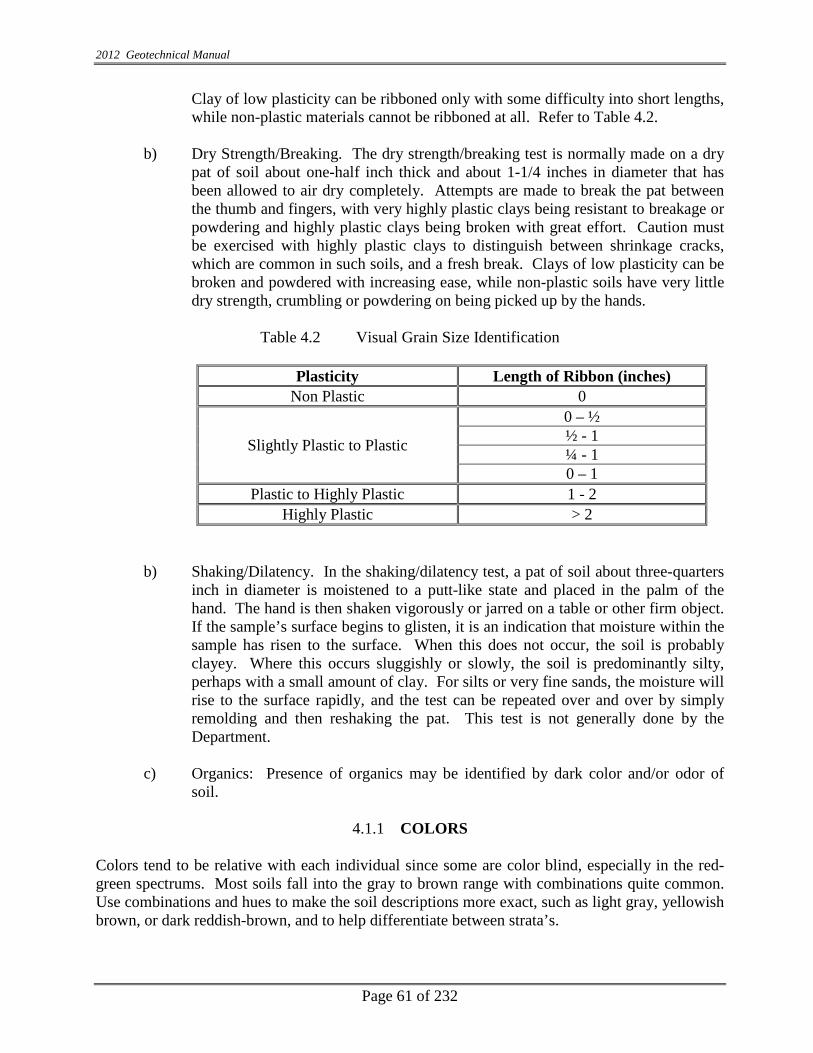
2012 Geotechnical Manual
Page 61 of 232
Clay of low plasticity can be ribboned only with some difficulty into short lengths, while non-plastic materials cannot be ribboned at all. Refer to Table 4.2.
b) Dry Strength/Breaking. The dry strength/breaking test is normally made on a dry
pat of soil about one-half inch thick and about 1-1/4 inches in diameter that has been allowed to air dry completely. Attempts are made to break the pat between the thumb and fingers, with very highly plastic clays being resistant to breakage or powdering and highly plastic clays being broken with great effort. Caution must be exercised with highly plastic clays to distinguish between shrinkage cracks, which are common in such soils, and a fresh break. Clays of low plasticity can be broken and powdered with increasing ease, while non-plastic soils have very little dry strength, crumbling or powdering on being picked up by the hands.
Table 4.2 Visual Grain Size Identification
Plasticity Length of Ribbon (inches)
Non Plastic 0
Slightly Plastic to Plastic
0 – ½ ½ - 1 ¼ - 1 0 – 1
Plastic to Highly Plastic 1 - 2 Highly Plastic > 2
b) Shaking/Dilatency. In the shaking/dilatency test, a pat of soil about three-quarters inch in diameter is moistened to a putt-like state and placed in the palm of the hand. The hand is then shaken vigorously or jarred on a table or other firm object. If the sample’s surface begins to glisten, it is an indication that moisture within the sample has risen to the surface. When this does not occur, the soil is probably clayey. Where this occurs sluggishly or slowly, the soil is predominantly silty, perhaps with a small amount of clay. For silts or very fine sands, the moisture will rise to the surface rapidly, and the test can be repeated over and over by simply remolding and then reshaking the pat. This test is not generally done by the Department.
c) Organics: Presence of organics may be identified by dark color and/or odor of
soil.
4.1.1 COLORS
Colors tend to be relative with each individual since some are color blind, especially in the red-green spectrums. Most soils fall into the gray to brown range with combinations quite common. Use combinations and hues to make the soil descriptions more exact, such as light gray, yellowish brown, or dark reddish-brown, and to help differentiate between strata’s.
2012 Geotechnical Manual
Page 62 of 232
Colors can be important. The changes in colors can help determine the changes in mineral content of the soils, or indicate fluctuations in groundwater. Dark soils can indicate organics such as peat, while light-greenish colors can indicate marly soils.
4.2 IN-SITU TESTING
4.2.1 HAND AUGERS
As described in Section 3.12.4 hand augers maybe used to determine the relative consistency of soil to a shallow depth.
4.2.2 POCKET PENETROMETER (PP)
The pocket penetrometer is a hand held calibrated penetration device and is commonly used to obtain an approximation of the unconfined compression test. It has a calibrated spring and 0.25 in. (6.4 mm) diameter piston encased inside a metal casing. The test is performed in the field on splitspoon samples and (although rarely) on auger cuttings. Occasionally, the penetrometer has been used on the ends of Shelby Tube samples for a quick field strength determination. When the piston is forced, by hand, to penetrate into the soil sample a distance of 0.25 in. (6.4 mm), at a constant rate, the calibrated spring is compressed into the penetrometer which gives an unconfined compression strength or Qu reading on the scale of the penetrometer. The use of the PP is valuable only as a guide or supplement to more precise strength determinations. They should not be used for design recommendations, stability or settlement analysis. Engineering judgment should be used with PP tests.
4.2.3 CONE PENETROMETER TEST (CPT)
1. Cone Penetrometer Testing is a modern, expedient and cost-effective approach to soil exploration. It involves pushing an instrumented electronic probe into the soil while continuously recording multiple measurements at the depth pushed. Results are immediately available for soil types and delineation, tip resistance, sleeve friction and pore water pressure and in some cones, shear wave or seismic wave testing. It’s quicker too because a large amount of high quality, in-situ data can be obtained without the extended time required for lab testing samples.
2. The CPT system has five components; an electrical Penetrometer, a hydraulic pushing
system which includes rods, a cable transmission device, depth recorder and a data acquisition unit. A dedicated operator of the data system to keep up with new and improved software and a driller to handle the rods is all that is required once a hole has been opened through the pavement to push through.
3. Data received from the cone is transmitted to a depth logger and computer for storage and
then downloaded into the INDOT Geotechnical Section’s information database (gINT)to be used in the engineering analysis and implementation into the geotechnical report.
2012 Geotechnical Manual
Page 63 of 232
The CPT, used in combination with SPT, is sometimes the best approach to any deep and difficult project and is rapidly becoming a normal testing procedure for many geotechnical investigators.
4.2.4 DYNAMIC CONE PENETROMETER TEST (DCPT) Dynamic Cone Penetrometer Testing is a test which provides a measure of a material’s in-situ resistance to penetration. The test is performed by driving a metal cone into the ground by repeated striking of a 17.6 lb. hammer from a distance of 2.26’. The penetration of the cone is measured and recorded after each drop with a penetration of up to 5’ below the ground surface. Results of the DCP tests can be correlated to California Bearing Ratios (CBR), in-situ density, resilient modulus, and bearing capacity of the soils. An advantage is that compared to other types of soil testing equipment, the DCP apparatus is relatively inexpensive for portable, hand operated devices. (More expensive, automated rigs can be purchased which must be towed.) Another advantage is that dependant upon the test apparatus, depth of testing and the condition of the subgrade, it requires only about 5 to 10 minutes to perform the test and only 1 or 2 people to conduct it efficiently. INDOT is implementing the use of the DCP tests in pre-construction locations for road widening and intersections and during construction for new sub-grades.
4.2.5 STANDARD PENETRATION TEST (SPT) The SPT test is described in section 3.12. The SPT is performed for two, primary, purposes: 1) to obtain a representative sample of the subsoil strata for purposes of identification, classification, unconfined compression testing, moisture and density tests; and 2) to obtain a measure of the relative density and/or consistency of the soils. It is the only simple, widely used test, presently available, to determine design data for cohesionless soils. The results of the SPT test can usually be correlated, in a general way, with the relative density of granular cohesionless soils; and, in a less reliable way, with the consistency or compressive strength of fine-grained cohesive soils, as described in this section.
4.2.6 LIGHT WEIGHT DEFLECTOMETER (LWD) A Light Weight Deflectometer is a very portable apparatus which is used to determine the stiffness of unconsolidated materials during construction by measuring the deflection under an applied load, or in simple terms, to insure that the in place foundation materials are compacted enough to provide a stable foundation for the pavement. The device is hand operated and takes measurements of the deflection of the compacted soils impacted by a falling weight. It measures deflection and estimates a modulus value based on the force required to generate a given deflection for that soil type.
4.2.7 PRESSURE METER (PM)
2012 Geotechnical Manual
Page 64 of 232
A pressure-meter test is an in-situ, stress-strain test, performed by inserting a cylindrical probe into an open borehole, supporting it at the test depth, and then inflating a flexible membrane in the lateral direction to a radial strain of as much as 40% depending on the probe design. To obtain viable test results, the hole must be pre-drilled and there must be knowledge of the type of soil or rock which will be tested. It can be conveniently used with drilling equipment or pushed in with direct push equipment. While tests can be done in soft clay or loose sands, the test is best used in dense sands, hard clays and weathered rock which cannot be tested with push equipment. An extensive database of load test results allows the geotechnical engineer to accurately design for shallow foundations and for lateral and vertical capacity of deep foundations.
4.3 DRILLER’S FIELD LOGS
Soil types are directly related to the parent materials of the area whether it be glacial, alluvial, loess, residual or combinations. However, it changes in urban areas, constructed areas, and where surface mining has changed the landscape. In these locations, the soils are unpredictable from inconsistent fills or strata. Until the soils can actually be tested in the lab, the drillers’ field log is the prime source of information for the geotechnical engineer or geologist in the office, so it is a requirement that logs be filled out in a consistent format with the most accurate information possible. Indiana Department of Transportation has formatted a log, which satisfies the requirements of the engineers of the Geotechnical Section. This log shows the following information: a). project designation numbers and locations; b). boring number; c) drilled location by reference to station, offset, survey line; d). method of boring, type of sampling, and type of drill; e). date of boring and weather conditions; f). ground elevation measured by utilizing a transit or level instrument in reference to a known benchmark, or taken from the contours of cross-sections plotted on the project’s plans; measured thickness and depth of various strata, in English Standard (metric) below ground surface or by elevation; h). a complete description of each strata which must include, but is not necessarily limited to, the color, moisture, consistency or density and visual grain size classification; i). The depth of free water encountered during drilling, at the completion of drilling and 24 hours later; j). the number of blows per 6 inch (15 mm) increments of drive of the splitspoon sampler, sample number and the top and bottom depth of the sample; k). percent (%) recovery on splitspoons, shelby tubes and rock cores; l). county; m). driller and inspector; n). field identification number, o). backfilling method (including materials used) and cave-in depth; p). any other pertinent information related to the boring should be added under the “office” heading. An example of the INDOT field Boring Log is Appendix 3 (4.1). q). Geographic location and datum as determined by a gps devise with a minimum accuracy of +3m.
Fill or embankment material should also be tested and classified with the depths of the strata included on the logs. Also, when drilling through a bridge deck, and into water, all thicknesses of the deck, space to water, and water depth is to be recorded. The actual depths of the strata should be included on the logs. The actual depth the boring starts shall be that point at which a sample can be obtained and shall be considered as sample number one. It’s important to record all the information since it is used in determining pay quantities for consultants drilling.

2012 Geotechnical Manual
Page 65 of 232
When taking rock cores, the boring logs require the same information, but a more complete description of the core sample is necessary. See Section 4.7 for more information. All completed driller’s field logs are entered into the gINT Soil Data System. The gINT data program will generate computerized logs and charts based on the splitspoon sample data from the field logs and tested lab samples. Cone Penetrometer Test log information is digital upon retrieval from the boring and accompanying software allows the data to be converted to charts and graphs for easy interpretation. This CPT data is also compatible to the gINT Soil Data Retrieval System.
4.3.1 AUGER REFUSAL
Auger refusal is a relative term and engineers should discuss the need with the Chief Geotechnical Engineer for various foundation options. Auger refusal may be considered when the penetration rate of the hollow stem auger (HSA) is less than 6 in. for 10- minutes, at a down pressure of 500 psi. The penetration rate of the HSA into shale or soft rock shall be attempted with various down pressures such as 300 psi, 400 psi, and 500 psi and a record of the down pressure and penetration rate shall be noted on the boring logs.
4.3.2 ABBREVIATIONS ON LOGS
For consistency in log writing and interpretation, abbreviations for commonly used terms are listed below. Terms which are not on the chart are probably not common so should be spelled out for clarity.
Table 4.3 Abbreviations to Be Used On Boring Logs
Abbreviations of Geotechnical Terms Abbreviation Description Abbreviation Description
agg Aggregate fm Formation amt Amount fos Fossiliferous & And frag Fragments
approx Approximate Gvl Gravel AR Auger Refusal gry Gray asph Asphalt > Greater than or Greater @ At grn Green
B-F Backfilled HA Hand Auger bdd Bedded hd Hard blk Black HSA Hollow Stem Auger blu Blue I Interstate br Brown JS Jar Sample
BTH Bottom of Test Hole km Kilometer Ca/mg Ca/mg < Less than or Less CBR California Bearing Ratio lt Light
ch Chert lo Loam CI Centerline m Meter

2012 Geotechnical Manual
Page 66 of 232
Abbreviation Description Abbreviation Description CL Clay LS Limestone
compl Completion mat’l Material CFA Continuous Flight Auger marl Marl Dk Dark med Medium den Dense mi Mile diff Different mm Millimeter Dis Disintegrated mo Moist DC Dry at Completion mot Mottled D24 Dry after 24 hours N North
E East org Organic elev Elevation Pt Peat % Percent S-5 Sample Number 5 etc.
PHA Power Hand Auger SS Split Spoon PT Push Tube SR State Route RC Rock Core st Stiff
RQD Rock Quality Designation tr Trace R. Bit Roller Bit US United States Road (Route)
Sa Sand, Sandy USC & GS U.S. Coastal & Geologic Survey Sh Shale V Very Si Silt, Silty wthrd Weathered Sl Slightly W West so Soft w/ With
4.4 SOIL STRENGTHS, TEXTURES AND GENERAL TERMINOLOGY
The Standard Penetration Test (SPT) is used for in-situ testing of soils and, in most cases, fifty (50) hammer blows is maximum taken for 6 in. penetration before termination in ground, this will be extended to complete a 6 in (152 mm) increments or in extremely hard soils or soft rock, to obtain a minimum sample length for visual classification. Cohesive Soils (Clay and Plastic Combinations)
Blows per foot Consistency 0 – 3 Very Soft 4 – 5 Soft 6 – 10 Medium Stiff 11 – 15 Stiff 16 – 30 Very Stiff Over 30 Hard

2012 Geotechnical Manual
Page 67 of 232
1) None Cohesive Soils (Sands, Silts and Non-plastic combinations)
Blows per foot Consistency 0 – 5 Very Loose 6 – 10 Loose 11 – 30 Medium Dense 31 – 50 Dense Over 50 Very Dense
3) Percentage Modifiers
Modifiers should be added to classifications to further help identify materials contained in the soils. These materials could be gravel, rock fragments or various man-made items and can be described as given below based on the percentage amount.
With a Trace of 0 to 10%
With Little 11% to 20% With Some 21% to 35%
And 36% to 50%
Organics or marl contents have a different range of percentages See Section 4.11.2 for this information.
4.5 GROUNDWATER ELEVATIONS All groundwater information is important and any observations should be recorded on the drilling logs to verify or establish the water table at the boring locations. These observations should be recorded at these intervals: 1) During Sampling: Note water on the rods, split spoon or Shelby Tube samples at the time
of extraction from the test hole. If the boring was drilled without the use of water, the groundwater elevation is related to the permeable strata but it may also represent a temporary or perched water table. Permeability is increased by fissures and blocky or crumbly soil structures with these structures being a direct result of frequent wetting and drying, commonly near the surface. Thus, the groundwater elevation in the bore hole may be a function of the piezometric conditions in the more permeable strata. Uniform deposits of fine grained, especially cohesive, soils are practically impermeable and groundwater flow through such strata is negligible.
2) If water has been used during drilling, it should be noted on the drillers’ field log. 3) At the Time of Completion of the Soil Boring: Carefully measure the elevations of the
water, after the augers are removed and also measure the cave-in depth (if any). Again, if

2012 Geotechnical Manual
Page 68 of 232
water has been used during drilling, it should be noted on the drillers’ field log. It may be necessary to pump or bail out the bore hole to observe the groundwater elevation changes.
4) 24 Hour Water Reading: Twenty-four hours is the accepted minimum time required for
the groundwater in most soil borings to reach equilibrium. Unless a granular layer is encountered, a subsequent groundwater elevation should not be made before the 24 hours has elapsed and if the field personnel determine this equilibrium has not yet been established, then additional readings may be necessary.
Twenty-four hour readings are so important that on projects where it is impossible to leave open borings because of public safety, we ask that a sounding of equal depth be performed in a safe area, close to the original boring. Sand heave, a condition which occurs when an exceptionally permeable layer (usually medium to fine grained sands) is saturated with groundwater creating a high pressure area. It should be noted that on the drillers’ and finished logs, “Heaving Sand” is a driller’s nightmare and can also be a contractor’s headache when not warned about it before construction begins. In Indiana, failure to note heaving sand on the logs has resulted in major cost overruns on projects when coffer dams had to be constructed to control the water-filled sand layer.
4.6 GROUNDWATER AND BACKFILLING Note and record depth to ground water encountered during drilling. When water is added during drilling to keep the hole open, the depth should also be noted on the boring log. After measuring the ground water level at completion of the borings, the bore holes shall be suitably covered so that there will be no hazard to people, animals or equipment. It may be necessary to use a PVC casing in order to keep the hole open to record twenty-four (24) hour readings. After the twenty-four (24) hour ground water level has been measured as well as the depth to which the hole remained open, (or cave-in to) and all other observations, records and information have been obtained, the holes shall be backfilled in strict compliance with the current Indiana Department of Transportation’s “Aquifer Protection Guidelines” dated 9 December 1985 and revised 30 October 1996 (including in appendix). Borings drilled through existing pavement should be suitably patched. Computation of final ground level may be done using Hvorslev’s method by measuring the rise and fall for two or more equal intervals. Methods of computing ground water levels are given below: (Next Page) .

2012 Geotechnical Manual
Page 69 of 232
GL
Figure showing computation of final groundwater
D = Dw + Ho
= Dw + H1 + ℎ1 + ℎ2 = Dw + H2 + ℎ1 + ℎ2 + ℎ3
∆T1 = ∆T2 = ∆T3 = ∆T
4.7 FIELD IDENTIFICATION OF ROCK In rock mechanics, it is necessary to distinguish between rock mass and a rock sample. A rock sample is the material between any structural discontinuity in a rock mass. Rock mass is the aggregate of regular or irregular blocks of rock material. The blocks are separated by structural features such as bedding planes, joints, fissures, cavities and other discontinuities. The loss of water during drilling process may indicate discontinuities in rock mass. The loss of water during drilling process may indicate discontinuities in the rock mass.
▼Final groundwater
D
Dw
Ho
H1 H2
ℎ3 ∆T3
ℎ2 ∆T2
ℎ1 ∆T1 Water level at t=0 after boring
21
12
hhhHo−
=
21
21
2
hhhH−
=
32
32
2
hhhH−
=

2012 Geotechnical Manual
Page 70 of 232
When rock cores are obtained, it is important to measure the core recovery and the RQD. The core recovery ratio is the length of rock core recovered from a core run, divided by the total length of the core run. This ratio gives indications regarding the presence of weathered zones, plugging during drilling, loss of fluid, and recut or rolled pieces of core. The RQD, expressed in percent, is the sum of the lengths of all pieces of sound core over 4 in. (100 mm) long, recovered from a core run, divided by the length of the core run. For example, if the core length is 40 in. (1000 mm) and there are 10 rock pieces, 7 of which with lengths less than 4 in. (100 mm) and 3 pieces with lengths of 4 in. (100 mm), 5 in. (125 mm.) and 6 in. (150 mm), respectively, the RQD for this core is 37.5%. The piece length is an average length which should be measured at the midpoints on each end. There are correlation’s between the RQD and the average quality and strength of a rock mass. A correlation between the RQD and the rock quality is given below.
RQD % Rock Quality 90 – 100 Excellent 75 – 90 Good 50 – 75 Fair 25 – 50 Poor 0 - 25 Very Poor
LABORATORY TESTING
4.8 GENERAL: WEIGHT VOLUME RELATIONSHIP
In nature, soils are three-phase systems consisting of solid soil particles, water, and air (or gas). To develop the weight-volume relationships for a soil, the three phases can be separated as shown in Figure 3.1a. Based on this separation, the volume relationships can be defined in the following manner. Void ratio, e, is the ratio of the volume of voids to the volume of soil solids in a given soil mass, or
Equation (4.1) where Vv = volume of voids Vs = volume of soil solids Porosity, η, is the ratio of the volume of voids to the volume of the soil or,
Equation (4.2) where V = total volume of soil Moreover,
Equation (4.3)
VsVv
=e
VVv
=η
100(%) xrun core Total
more or in. 4 minimum of sampleRockRQD ∑=
ee
VsVv
VsVs
VsVv
VvVsVv
VVv
+=
+=
+==
1η

2012 Geotechnical Manual
Page 71 of 232
Degree of saturation, S, is the ratio of the volume of water in the void spaces to the volume of voids, generally expressed as a percentage, or S = Vw/Vv, S (%) = Vw / Vv X 100 Weight Volume Relationship
Total Weight = W W = Wa + Ws + WW = Ww + Ws (Wa~0) Wa = weight of air Ww = weight of water Ws = weight of solid Total Volume = V V = Va + Vw + Vs
Va, Vw, and Vs are volumes of air, water and solids in the soil.
Specific Gravity of solid (G = Gs)
γs and γw are unit weights of solid and water.
Weight of solid Ws Ws = γs x Vs = (G yw) x Vs = G yw (when Vs = 1)
(a) Components of Soils
Figure 4.1 Weight Volume Relationship
Wa
Ww
Ws
V
Vs
Va
Vw W
Volume Weight Volume Weight
Solid
Water
Air
Soil
w
sGγγ
=

2012 Geotechnical Manual
Page 72 of 232
(Note: Vw = w Gs=se, when Vs = 1) (b) Unsaturated soil; Vs = 1, three phase diagram
Vw = Vv = e
(c) Saturated soil; Vs=1
Figure 4.1 (Con’t.) Weight-volume relationships, two phase diagram
Equation (4.4) Where Vw = volume of water Note that, for saturated soils, the degree of saturation is 100%. The weight relationships are moisture content, moist unit weight, dry unit weight, and saturated unit weight. They can be defined as follows: (i). Moisture or water content (%) =w=
Equation (4.5)
100) xVvVwS(% =
Ww=e yw=G Yw
Ws=Gsγw (Vs=1)
Volume Weight
Solid
Water
Ws = Gγw x Vs = Gγw (Vs = 1)
Vv = e
Ww =Vw x Yw
Wa = 0
Water
Air
Solid Vs = 1
100)(
)(×
s
w
WsoildryofWeightWwaterofWeight
Vv = Va + Vw Va
Vs
Vw=wGs=e
Vs=1

2012 Geotechnical Manual
Page 73 of 232
)1()(Gw
sate
e++
=γγ
(ii). Moist (Natural or Bulk) density (lb/cu ft)
Equation (4.6) (iii). Dry unit weight Y dry (lb/cu ft).
Equation (4.7) (iv). Saturated unit weight (lb/cu ft)
Equation (4.8) (v). Submerged unit weight (lb/cu ft)
Equation (4.9) Where G = Gs = specific gravity of solids of soils
γ w = Unit weight of water (62.4 lb/cu ft)
4.9 MOISTURE CONTENT This test shall consist of determination of moisture content in accordance with AASHTO T-265, on all fine grained soil samples. It is important to note that the moisture content (w) is expressed in percent as expressed in equation 4.5. This test shall not be performed on soils with passing #200 Sieve (0.075 mm) less than 35% without prior approval.
ew
++
==1
)1(YG wsbulk γγ
ew
+=
11)-(G - wsat
γγγ
eG w
w +=
+=
11 dry
γγγ

2012 Geotechnical Manual
Page 74 of 232
4.10 SPECIFIC GRAVITY TEST This test shall be performed in accordance with AASHTO T-100. Most Indiana soils shall have specific gravities ranging between 2.60 to 2.75. Soils with organic content or porous particles such as slag or coal combustion by-products may have specific gravities which are much lower.
4.11 CLASSIFICATION TESTS
4.11.1 GRAIN SIZE ANALYSIS
These tests shall be performed on samples that were obtained for verification of the field classification of the major soil types encountered during the investigation. The number of tests shall be limited to reasonably establish the stratification without duplication, unless approved otherwise. A minor soil type, if not critical, may be given a visual classification, instead of performing classification tests for reference.
1) Sieve Analysis: A sieve is quantitative determination, of the distribution of particle
sizes present in the soil sample. The testing will be accompanied by means of sieve and hydrometer analyses. This test consists of determining gradation of a sample in accordance with AASHTO T-88 and Indiana Department of Transportation’s triangular classification chart as given in this section. All the soils shall be classified in accordance with AASHTO M-145.
Sieves shall be U.S. sieve sizes, seventy-five (75) millimeter, fifty (50) millimeter, twenty-five (25) millimeter, 9.5 millimeter and U.S. 4.75 millimeter, 2 millimeter, 0.425 millimeter, 0.075 millimeter, decanted over the 0.075 millimeter.
2) Hydrometer Analysis: This work shall consist of the Hydrometer Analysis in
accordance with AASHTO T-88, and includes a Specific Gravity Determination performed in accordance with AASHTO T-100. If twenty percent (20%) or more passes the Sieve 0.075 millimeter a Hydrometer Analysis shall be performed. A grain-size distribution curve shall be provided and should include the combined results of the Sieve Analysis.
4.11.2 ATTERBERG LIMITS AND PLASTICITY INDEX (PI)
The Liquid Limit (LL) is determined according to AASHTO T-89 method. The Plastic Limit (PL) and Plasticity Index (PI) are determined according to AASHTO T-90. A fine grained soil can exist in any of several states of consistency. The state of consistency, and the behavior of any particular soil depends primarily upon the amount of water present in the soil-water system. In 1911, A. Atterberg defined the boundaries of four (4) states of consistency, in terms of limits. These limits and the zones between the limits are illustrated in Figure 4.2.
Each limit represents a moisture content, beyond which the soil changes from one state to another. The PI (Plasticity Index) represents the range of moisture contents, through

2012 Geotechnical Manual
Page 75 of 232
which the soil is in the plastic state. The PI is simply the moisture content at the LL, minus the moisture content at the PL. The limits are useful for soil classification and correlation with the soil behavior; such as, compressibility, permeability, shrink/swell and strength. The SL can be useful in predicting the maximum loss of volume, which an embankment material may undergo when removed from a wet borrow, and subsequently dried and rolled into a fill. As soil dries to the SL, there is a loss of volume and water. Further drying removes water only, without corresponding volume loss.
Liquid State LIQUID LIMIT (LL) Plastic State PLASTIC LIMIT (PL) Semisolid State SHRINKAGE LIMIT (SL) Solid State DRY
Figure 4.2 Soil Water Scale Showing Atterberg Limits And Corresponding Physical States Of Soil In The Remolded Condition
The LL, PL and SL are arbitrary boundaries, but the procedures for obtaining these values have been standardized. The LL is determined in the lab by measuring the moisture content at which a standard groove of soil, placed in a standard brass cup, will close when the cup is dropped 25 times from a 0.394 in. (10 mm) height. The PL is determined by measuring the moisture content at which a thread of soil begins to crumble, when rolled into a 1/8 in. (3 mm) diameter. The SL is determined by drying a saturated soil, and measuring the limiting moisture content at which no further volume changes occur with loss of water.0
Plasticity index of A-7-5 subgroup is equal to or less than Liquid Limit minus 30. Plasticity Index of A-7-6 subgroup is greater than Liquid Limit minus 30. Note: Additional parameters of group index (GI) are determined to classify fine soils.
Group Index (GI) Group Index shall be calculated after performing the classification and Atterberg Limit and is reported along with the Classification Test. Group Index indicated the plastic nature of the portion of the material passing No. 200 sieve. Calculation of the group index is the final part of the AASHTO Classification. Generally, the higher the value of the group index for a given classification, the poorer the performance of the soil.

2012 Geotechnical Manual
Page 76 of 232
The formula used to calculate the group index is as follows. GI = Group Index. Reported as a positive whole number or zero. F = Percentage passing the No. 200 sieve. LL = Liquid Limit. PI = Plasticity Index.
)10)(15(01.0)]40)(005.02.0)[(35( −−+−+−= PIFLLFGI

2012 Geotechnical Manual
Page 77 of 232
Table 4.4 Classification of Soil and Soil-Aggregate Mixtures from AASHTO M-145
General Class.
Granular Materials (35% Or Less Passing No. 200)
Silt-Clay Materials (More than 35% Passing No. 200)
Group Class.s
A-1 A-3
A-2 A-4
A-5
A-6
A-7
A-1-a A-1-b A-2-4 A-2-5 A-2-6 A-2-7 A-7-5 A-7-6
Sieve Analysis, %
Passing
No. 10 No. 40 No. 200
50 max. 30 max. 15 max.
_____ 50 max. 25 max.
______ 51 min. 10 max.
______ ______ 35 max.
_____ _____
35 max.
______ ______ 35 max.
______ ______ 35 max.
______ ______ 36 min.
______ ______ 36 min.
______ ______ 36 min.
______ ______ 36 min.
Charac.'s of Fraction
passing No. 40
Liquid Limit Plasticity
Index
______ 6 max.
______ N.P.
40 max. 10 max.
41 min. 10 max.
40 max. 11 min.
41 min. 11 min.
40 max. 10 max.
41 min. 10 max.
40 max. 11 min.
41 min. 11 min.
Usual types of
Significant Constituent Materials
Stone Fragments, Gravel and Sand Fine Sand Silty or Clayey Gravel and Sand Silty Soils Clayey Soils
General Rating as Subgrade
Excellent to Good Fair to Poor

2012 Geotechnical Manual
Page 78 of 232
INDOT Soil Classification
INDOT Textural Soil Classification
Definitions:
Boulder over 10“
Cobbles 10” to 3”
Gravel 3” to #10 Sieve
Coarse Sand #10 to #40 Sieve
Fine Sand #40 to #200 Sieve (0.075 mm.)
Silt 0.075 to 0.002 mm.
Clay Smaller than 0.002 mm.
Colloids Smaller than 0.001 mm Any Soil with organic content (as determined in accordance with AASHTO T-267), 3% or less is considered mineral soil.

2012 Geotechnical Manual
Page 79 of 232
a) Soils having 0 to 19% Retained on #10 sieve (Chart below may be used)
Classification % Sand & Gravel % Silt % Clay Sand 80-100 0-20 0-20
Sandy Loam 50-80 up to 50 up to 20 Loam 30-50 30-50 Up to 20
Silty Loam Up to 50 50-80 0-20 Silt 0-20 80-100 0-20
Sandy Clay Loam 50-80 0-30 20-30 Clay Loam 20-50 20-50 20-30
Silty Clay Loam Up to 30 50-80 20-30 Sandy Clay 50-70 0-20 30-50 Silty Clay 0-20 50-70 30-50
Clay 0-50 0-50 30-100
b) Soils having 20% or more retained on #10 sieve and more than 20% passing 200 sieve (Silt and Clay).
Classify in accordance with Paragraph A, followed by term describing relative amount of gravel according to the following:
20% to 35% gravel – “With some gravel” 36% to 50% gravel – “and gravel”
Examples: Clay Loam with some gravel Sandy Loam and gravel
c) Soils having 20% or more retained on #10 sieve less than 20% passing #200 sieve.
Classification % Gravel % Sand % Silt % Clay
Gravel 85-100 0-15 0-15 0-15 Sandy Gravel 40-85 15-40 0-20 0-20 Gravelly Sand 20-40 40-80 0-20 0-20 Sand and Gravel 20-50 20-50 0-20 0-20
Note: When the gradation of a given sample does not meet the requirements for any classification exactly, it shall be placed in the classification to which it comes the closest.
d) Organic Soils. The following classification system shall be used for organic
soils in accordance with AASHTO T-267.
Classification Percentage With Some Organic Matter 4<oc*<15
Organic Soil (A-8) 16<oc<30 Peat (A-8) More than 30
• Organic Content in Percentage

2012 Geotechnical Manual
Page 80 of 232
e) Marly Soils. The following classification system shall be used for marly soils
with calcium and magnesium carbonate content.
With Trace Marl 1% TO 9% With Little Marl 10% to 17% With Some Marl 18% to 25%
Marly Soil (A-8) No group index 26% to 40%
Marl (A-8) No group index More than 40%
4.12 pH TEST This test shall consist of performing the pH test in accordance with ASTM D-2976 using only distilled water. The test should be performed on all classification test samples, and others as necessary. When the test is performed on moderate to non-organic material, sample size should be 0.04 lbs (20.0 grams) of material passing the sieve size 4.75 millimeter. The samples shall be prepared in accordance with AASHTO T-87.
4.13 LOSS OF IGNITION This test shall consist of determination of the Loss on Ignition (Organic Content) in accordance with AASHTO T-267. This method will provide a quantitative estimation of oxidized organic matter in the soil mass. Organic matter present in soil shall be reported as a percentage in full number (not in fraction).
4.14 UNIT WEIGHT DETERMINATION
This test shall consist of the determination of the Unit Weight by measurement of the length and diameter of sample. The procedure to determine unit weight is also described in EM-1110-2-1906 App. II of the Corps of Engineers.
4.15 STANDARD MOISTURE-DENSITY RELATIONS
This work shall consist of performing the Standard Moisture-Density Relations in accordance with AASHTO T-99 Method D. A minimum of four (4) points on the curve with at least two (2) points on each side of optimum shall be performed in conjunction with all CBR test samples, and shall be prepared and tested in accordance with AASHTO T-193 except the sample shall be mixed and then cured for forty-eight (48) hours prior to molding the specimens. AASHTO T-99 Method D shall be used in conjunction with all CBR tests.

2012 Geotechnical Manual
Page 81 of 232
Figure 4.3 Typical Curve Showing the Relationship Between Moisture Content and Dry Density. Zero Air Voids Curve Represents 100% Saturation.
4.16 ONE DIMENSIONAL CONSOLIDATION TEST This work shall consist of performing the consolidation test in accordance with AASHTO T-216 except the load increments shall be 0.06, 0.12, 0.25, 0.50, 1, 2, 4, 8, and 16 T/Sq.Ft. This test also includes Specific Gravity, Initial and Final moisture Content tests, Initial and Final Degrees of Saturation and Unit Weights (density). Time curves for all load increments and e-log-p curve shall also be furnished. Laboratory data, sheets and e-log-p graph sheets are included in Appendices 5 (4.3) to 7 (4.5).
4.17 UNCONFINED COMPRESSIVE STRENGTH TEST
This test is commonly referred to as the Qu Test, and shall consist of performing the Unconfined Compressive Strength Test in accordance with AASHTO T-208. This test includes determination of initial and final moisture contents, unit weight determination, visual descriptions of the soil, average rate of strain to failure and strain at failure. The sample shall be undisturbed and have a minimum diameter of 1.3 inches (33 millimeters) unless other types are approved in advance for the specific project. The test is a special case of Triaxial Compression Test in which the confining pressure, (σ3) is zero as shown in Figure 4.4. It is performed by loading a soil specimen at a constant rate, to the failure load. It may be expressed in tsf, or kPa, or in terms of any force per unit area. It is important to note that the angle of internal friction, φ is assumed to be zero in case of clay. Cohesion or shearing strength as denoted as c or s is equal to one-half qu for pure clay. This test is not suitable for granular soils. Failure load is the load at which sample fails or the load corresponding to 15% strain whichever occurs first. The data sheet to represent stress and strain during these tests is presented in Appendix 8 (4.6). When a rock core is obtained for trenchless pipe installation, the uni-axial compressive strength of the sample shall be determined in accordance with AASHTO XXXX.
Zero Air Voids Curve
Dry Density
(MDD)
Optimum Moisture Content

2012 Geotechnical Manual
Page 82 of 232
σ1
σ3 = 0 σ3 = 0
4.18 HYDRAULIC CONDUCTIVITY
This test is conducted to determine the rate of flow of water through the soil mass. Hydraulic conductivity is determined to know the drainage property of subgrade and base materials. It is determined as the following:
σ1
Figure 4.4 UCS Loading
1) Rigid Wall Method
a) Constant Head. A constant head test, as described in detail in AASHTO T-215 (ASTM 2434), is generally used to determine the hydraulic conductivity of granular materials. The sample for testing is selected and compacted into the mold. (The compactive efforts affect the hydraulic conductivity.) It is then saturated under vacuum to assure that there is no air in the sample. Water is then allowed to flow through the sample from the constant head tank to a collector tank. Water is continually added to the constant head tank to maintain the water level.
b) Falling head. A falling head test can be used to determine the hydraulic
conductivity of fine-grained soils. The sample should be compacted and saturated as above for the constant head test. The constant head tank from the previous test is replaced with a burette. The difference in water level from the burette to the collector tank is measured and recorded as h1. Water is then allowed to flow out of the burette and into the collector tank. Once a predetermined change has occurred, the head is measured again and recorded as h2. The time required for the change in head and the temperature of the test water should also be recorded.
2) Flexible Wall Method

2012 Geotechnical Manual
Page 83 of 232
Hydraulic conductivity test simulated to various confining pressure and pressure differential may be conducted using flexible wall parameters as per ASTM D-5084. This method is preferred for less pervious soils. It is recommended to use flexible wall per parameter (ASTM D-5084) for relatively less permeable soils (K < 1 x 10 –3 cm/sec) and rigid wall method (AASHTO T-215) for soils with higher permeability (k > 1 x 10 –3 cm/sec).
4.19 TRIAXIAL COMPRESSION TEST
This test shall consist of performing the Triaxial Compression to determine the shear strength parameters. Each test shall consist of at least three (3) points for plotting a Mohr Failure Envelope and determining the strength parameters. This test shall include initial and final Moisture Content tests, specific gravity, Atterberg Limits, initial and final void ratio initial and final degrees of saturation, Unit Weight (density), visual Textural description, plot of Mohr circles and envelope and sketch of failure.
TRIAXIAL TEST
Figure 4.5 Triaxial Tests, Step I and Step II
σ1 Fig 4.6 Triaxial Test-Final Step
The test may be one of the following types.
+
σ3
σ3
σ3
σ3
σ1-σ3
σ1-σ3
σ3
σ3
σ3
σ1
σ3

2012 Geotechnical Manual
Page 84 of 232
(1) Unconsolidated – Undrained (UU) test, quick test. (2) Consolidated – Undrained (CU) test. (3) Consolidated – Drained (CD) test, slow test.
The UU test is the most common test method. In which no drainage from the sample is permitted, either during the application of the confining pressure, or during the axial loading to failure. This is referred to as Total Stress Analysis. The CU is a test method in which drainage of a sample is allowed during confining pressure, however, no drainage is allowed during axial loading. This is referred to as Effective Stress Analysis. The UU and CU Triaxial tests are to be conducted in accordance with AASHTO T-296 and AASHTO T-297 test methods, respectively. These tests may be performed on all the soils ranging from Cohesive to Completely Cohesionless. Consolidated drain test or Slow Test (CD) is generally conducted for earthen embankment or landfill construction. Consolidated drained (CD) or slow test is the method in which drainage from the sample is permitted in both conditions during confining pressure as well as during axial loading. The calculation for the triaxial tests is done according to the data sheet as presented in Appendices 10 (4.8) and 11 (4.9).
4.20 CALIFORNIA BEARING RATIO (CBR)
This work shall consist of the determination of California Bearing Ratio values in accordance with AASHTO T-193 with the following exceptions.
1. Three (3) specimens shall be molded at optimum moisture content, one at approximately
ninety (90) percent, one at ninety-five (95) percent, and one at one hundred (100) percent, of the maximum dry unit weight, respectively.
2. The samples shall be molded between –0.8 percentage to +0.8 percentage of optimum moisture content.
3. A minimum surcharge weight of 22, 26, and 30 lbs. shall be applied based on the volume of estimated traffic. However, 25 to 30 lbs. has been found acceptable.
4. California Bearing Ratio tests shall be performed on the soil which has a maximum unit weight of at least one hundred (100) pcf.
5. A dry unit weight (abscissa) versus CBR (ordinate) curve shall be plotted and furnished for each sample tested, or the graph as shown in Appendix 12 (4.10). other data for CBR tests should be presented on the data sheet as shown in Appendix 13 (4.11).
Note: CBR test shall not be performed on the granular soil without prior approval.

2012 Geotechnical Manual
Page 85 of 232
4.21 RESILIENT MODULUS (Mr) Resilient modulus of subgrade soil should be determined as per AASHTO T-307 or other procedures as specified by INDOT. For rubbilization resilient modulus of subgrade soil should be conducted on a sample molded at in-situ density. Results of Resilient Modulus Test should be presented as described in item 49(b) in Appendix 16, Services to Be Furnished by Consultant, (Appendix A). A sample of laboratory test data is presented in Appendix 13a, (4.21).

2012 Geotechnical Manual
Page 86 of 232
CHAPTER 5
GEOTECHNICAL ANALYSES
5.0 INTRODUCTION As soon as the soils exploration program is complete and the data is available, the geotechnical engineer should be ready to start the geotechnical analyses. Good geotechnical analyses begin with a good understanding of the soil data, profile, and parameters. The intent of this chapter is to provide general guidance to identify the soil and foundation concerns that needs to be evaluated, and the current requirements that the analysis should satisfy. It is presumed the engineer is familiar with all aspects of geotechnical engineering, as they relate to the behavior of highway structures and roadways. The term, “analyses” in this section does not, necessarily, include all the mathematics needed to analyze a certain situation. The design analyses contained in the Geotechnical Report should be in compliance with current requirements given in this INDOT Geotechnical Manual and Guidelines. The current FHWA and NHI manuals should be consulted for more detailed guidelines. For any other specific requirement not covered in this manual prior approval of the Chief Geotechnical Engineer should be obtained. NOTE: All geotechnical designs for shallow and deep foundation (footings, bridges) and other retaining structures will be done by LRFD method in accordance with the guide lines given in the following documents: 1. AASHTO LRFD Bridge Design Specification 2007 17th ed, and any latest addition. 2. LRFD for highway structures: FHWA-NHI 05-094 and FHWA –NHI -06-098 3. INDOT Spec-2011.
5.1 SETTLEMENT ANALYSIS This section addresses only the consolidation settlement in the natural ground, under the embankments. Normal construction practices are usually adequate to preclude excessive post construction consolidation within the embankment. Consolidation settlement takes place when the weight of the embankment exceeds the previous stress history of the underlying strata. In this case, the soil particles are pressed more closely together. The amount of settlement is a direct measurement of the reduction in the soil voids space. Soil settlement consists of primary and secondary consolidation. Primary consolidation is the portion of the consolidation curve in which the reduction in void ratio is associated with the dissipation of excess pore water pressure. The pore pressure depends on soil permeability, which is a function of the particle size. Granular materials are sufficiently permeable to dissipate excess

2012 Geotechnical Manual
Page 87 of 232
pore water pressure as quickly as the embankment load is applied. At the other extreme, thick deposits of wet, high clay content soil may not achieve equilibrium pore water pressure for decades. Secondary consolidation occurs after full dissipation of excess pore water pressure. Secondary consolidation is a problem with high organic deposits, such as peat. For peat, the total secondary consolidation could be twice as much as the primary consolidation. With mineral soils, the secondary consolidation is not commonly considered a problem. The consolidation characteristics of fine-grained soils are evaluated in the laboratory, on specimens taken from undisturbed soil samples. If consolidation test data is not available, the primary settlement(s) can be estimated using geotechnical parameters obtained from empirical relationships following are empirical formulas suggested by various researchers to calculate compression index (Cc) values.
Table 5.1 Correlation’s for Compression Index Cc*
Equation Reference Region of applicability Cc = 0.007(LL -7) Skempton Remolded clays Cc = 0.01wn Chicago clays Cc = 1.15(eo – 0.27) Nishida All clays Cc = 0.30(eo – 0.27) Hough Inorganic cohesive soil: silt, silty clay, clay Cc = 0.0115 wn Organic soils, peat’s, organic silt, and clay Cc = 0.0046(LL – 9) Brazilian clays Cc = 0.75(eo – 0.5) Soils with low plasticity Cc = 0.208eo + 0.0083 Chicago clays Cc = 0.156eo + 0.0107 All Clays
*After Rendon-Herrero (1980) Note: eo = in situ void ratio; wn = in situ water content Swell Index (Cs) The swell index is appreciably smaller in magnitude than the compression index and can generally be determined from laboratory tests. In most cases,
Equation (5.1) Calculation of settlement: For normally consolidated soils
Ρ∆+Ρ
+=
oo
eCHS
o
c P10log1

2012 Geotechnical Manual
Page 88 of 232
oo log e1 P
PPo
CcHS ∆++
=
Where Po is the existing pressure on the compressible layer due to soil strata above this layer (lb/ft 2). ∆P = Increase in pressure on the compressible layer due to construction at top (lb/ft2). eo = initial void ratio Normally consolidated soil is the soil which has not been subjected to higher pressure than existing total pressure (total pressure at present including any additional pressure due to construction at the surface) any time in the past. Pc = pre-consolidation pressure is the maximum pressure the compressible layer has been subjected to in the past (lb/ft2). For over consolidated soil the settlement may be calculated as given below: If (Po + ∆P) < Pc
Ρ∆Ρ+
+=
oPo
eCcrHS 10log
1 0
Equation (5.2)
If (Po +∆ P) > Pc
Equation (5.3) Cc = Compression index Ccr =Recompression index H = Thickness of compressible layer (ft.) eo = Initial void ratio For very soft to soft clays (Qu between 0.25 to 0.50 tsf), the settlements computed by this method are likely to be reasonably accurate. For medium and stiff clays (Qu between 0.5 and 2.0 tsf), the actual settlements are likely to range between one-fourth and one-tenth of the computed values.

2012 Geotechnical Manual
Page 89 of 232
The analysis of a proposed wick drain should include: design spacing at a specific embankment section based on consolidation test results. The consultant geotechnical engineer shall furnish an estimated coefficient of horizontal consolidation, a plot of percent total estimated settlement vs. time using the optimum wick drain design, the limits from station to station and offset to offset where the proposed wick drains should be installed with any other information needed.
5.2 STABILITY OF PAVEMENT SUBGRADE Subgrade stability must consider the short-term and long-term behavior of the subgrade. The subgrade should adequately support the heavy equipment during construction, with minimum rutting. The subgrade should also support the roadway during its design life. In addition to the subgrade requirements in the Standard Specification, there are field conditions, which must be considered during the life of the pavement structure. The stress level at the subgrade, under repeated peak axle load repetitions, must be maintained within the range of elastic response of the subgrade soil. Failure to do so will result in the yielding of the subgrade, resulting in loss of pavement support and pavement failure. Internal drainage of the pavement system and the subgrade can exert a profound influence on the pavement performance. As the ground water rises toward the subgrade, and particularly within the upper 6 inches of a fine grained soil subgrade, the soil is essentially saturated. The result is load support reduction.
5.3 STABILITY OF SLOPES Slopes of roadway embankments in fill and cut areas should be stable for efficient functioning of roadways. This section describes types and reasons of slope failure including the methodology to check the stability of slopes.
5.3.1 TYPES OF FAILURE
The principle modes of failure (slip) in soil or rock are; 1) rotation on a curved slip surface, approximated by a circular arc; 2) translation along a planar surface, whose length is large compared to depth below ground elevation; 3) displacement of a wedge shaped mass, along one or more planes of weakness. Other modes include: toppling of rock slides, block slides, lateral spreading, earth and mud flows in clayey and silty soils, and debris flows in coarse grained soils. As a work of caution, in stability studies, the geotechnical engineer should be aware of any ditches to be located at or near the toe of the slope. A slip circle could be a base circle, a toe circle, or a slope circle. A base slip circle develops when there is a significant thickness of weak foundation soil. The base of the failure arc is tangent to the base of the weak layer, and the arc will have a significant portion of its length in the weak soil. A toe slip circle develops in the embankment and

2012 Geotechnical Manual
Page 90 of 232
intersects at the toe. This happens, sometimes, when the embankment material becomes saturated and failure occurs. .A slope circle develops within the embankment intersects with the slope. Sloughing of the slope, due to erosion, is an example of a slope slip circle. A planar failure is more commonly associated with the shear plane following a thin zone of weakness, and is seldom far below the base of the embankment or toe of slope. The failure plane may develop at the soil shale contact, with seepage on the shale surface. The planar failure may also develop at the base of an embankment. This could happen when an organic layer and vegetative cover have been inadequately processed during construction, resulting in a built-in failure plane. Block movements are more common to cut sections through relatively competent soils; such as a weathered glacial till. The movements take place along secondary structural cracks and joints. Residual soils may also fall into this group, with the plane of movement taking place along relic joints and bedding planes.
5.3.2 REASONS FOR FAILURE
Slope failure takes place when the driving forces exceed the resisting forces. The force imbalance may be caused by one or more of the following situations. 1) Embankment (fill) slope:
a) Slope profile changes that add driving weight at the top, or decreases in the
resisting forces at the base. Examples would be the steepening of the slope or undercutting of the toe.
b) Vibrations induced by earthquakes, blasting, or pile driving. Depending on
their frequency and intensity, induced dynamic forces could cause either liquefaction or densification of loose sand, silt, and loess below the ground water surface. Dynamic forces could cause the collapse of sensitive clays, thereby, resulting in increased pore pressures.
c) Overstressing of the foundation soil. This may occur in cohesive soil during
or immediately after construction. Usually, short-term stability of embankments on soft cohesive soil is more critical than long-term stability, because the foundation soil will gain shear strength as the pore pressures dissipate. It may be necessary to check the stability for various pore pressure conditions. Usually, the critical failure surface is tangent to a firm layer underlying the soft soil.

2012 Geotechnical Manual
Page 91 of 232
2) Cut slopes:
The stability of cut slopes made in soft cohesive soils depends on the strength of the soil, the slope angle of the cut, the depth of the excavation, and the depth to a firm stratum (if one exists not too far below the bottom of the excavation). The stability of cut slopes in granular soil is highly influenced by the ground water level and friction angle. Cut slope failure in soil may result from the following: a) Changes in slope profile, which results in the increase of driving forces,
and/or a decrease in the resisting forces. Additional embankment on top, steeper side slopes, or undercutting of the toe are examples.’
b) An increase of pore water pressure, resulting in a decrease in frictional resistance in cohesionless soils, or swell in cohesive soils. An increase in pore pressure could result from slope saturation by precipitation, seepage, or a rise in the ground water elevation.
c) Progressive decreases in shear strength due to weathering, erosion, leaching, opening of cracks and fissures, softening, and gradual shear strain (creep).
d) Vibrations induced by earthquakes, blasting, or pile driving.
e) Earth slopes subjected to periodic submersion (for example, along streams subject to water fluctuations). Also, loss of integrity due to seepage water moving to the face of the cut (piping).
In addition to the above failures in cut slopes involving rock and/or soil may result from:
i) Chemical weathering.
ii) Freezing and thawing of water in the joints.
iii) Seismic shock.
iv) Increase in water pressure within the discontinuities.
v) Alternate wetting and drying (especially in expansive shales).
vi) Increase in tensile stress, due to differential erosion.
5.3.3 DISCUSSION While an analysis by hand is very helpful in understanding the mechanics of sliding earth masses, such analysis is time consuming. Computer aided procedures are available, and they provide a far more detailed analysis in less time. There are also rules of thumb that can be used to make a preliminary assessment of the Factor of Safety (FOS) to prevent failure. One such rule is: (Taylor’s equation)

2012 Geotechnical Manual
Page 92 of 232
H
6CFOSγ
=
Where: C = cohesion of soft foundation soil γ = unit weight of embankment soil H = Height of slope The FOS computed using the above equation should not be used for final design. This simple equation can be used to preliminarily check both slope and foundation (base) ’stability. If the factor of safety is less than 2.5, a more sophisticated stability analysis is required. A number of slope stability methods of analysis have been adapted for use with a computer, and without a doubt, there will be others in the future. The concern is whether or not the computer program represents the short-term and long-term conditions that exist in the field. For those analyses, the problem is described by a two-dimensional slice, and the slice is typically thin (such as 1 ft. thick). The program should have the capacity to represent the actual site conditions, by inclusion of all forces acting on each side. Some methods include the side forces on each slide, while other methods ignore these forces. Factor of Safety (FOS) computations shall be made for various assumed failure surfaces until an apparent minimum factor of safety has been established for each analysis. All models will be approved by INDOT prior to performing the analysis. A computer program (preferring XSTABL or latest version) should be used for analyzing. The printout of input data, output data and plot of failure surfaces should be included with the analysis. In case of surcharge loading a graph of surcharge height and pore pressure should be provided.
5.4 BRIDGE FOUNDATION ANALYSIS
Based on the encountered subsurface strata and proposed load, shallow or deep foundations will be required. 1) Shallow foundations are defined as spread footings, reinforced concrete mat, etc. Factored
bearing pressure for shallow foundations will be based on loading conditions including axial loads at each pier location.
2) Deep foundations are defined as piles, drilled shafts, etc. There are numerous static
methods available to estimate the ultimate bearing capacity for piles. Although most of these methods are based on the same basic theories, seldom will any two give the same computed capacity. In fact, owing to the wide range of values and assumptions stated in those methods, major discrepancies in the computed capacity sometimes result. In addition, methods that have not been universally accepted are difficult to review and compare with actual field tests.
It is for the above reasons that the INDOT Geotechnical Section is recommending that all Geotechnical Consultants review the methods, assumptions and values used by the INDOT Geotechnical Section to compute the nominal bearing capacity for piles. The Geotechnical Consultants should analyze both steel encased concrete piles and steel H-piles for most projects.

2012 Geotechnical Manual
Page 93 of 232
The following approach for calculating the nominal bearing capacity will be used in checking the nominal bearing capacities computed by INDOT’s Geotechnical Consultants. The pile capacity should be determined using the computer program DRIVEN which uses Nordlund’s and Tomlinson’s methods for cohesionless and cohesive soils respectively. A summary of the theory of these two methods is given below. A factor of safety of 2.5 should be used to calculate the pile capacity with these methods. The nominal capacity (Qult) of all driven piles may be expressed in terms of skin resistance (Qs) and point resistance (Qp); Qn = Qs + Qp
Equation (5.4) The value of both (Qs) and (QP) is determined in each layer based on either frictional or cohesive behavior of the soil. The strength of frictional soils is based on friction angle. Cohesive soil strength is based on undrained shear strength. The pile capacity of cohesive soil layers should not be computed with both friction angle and cohesion values. When performing pile analyses please make note that the maximum nominal soil, geotechnical resistance shall be based on the following attached table. The nominal driving resistance may exceed these limits for friction piles if proven by a drivability analyses. It is not necessary to address the structural design in the geotechnical report.
Maximum Nominal Soil Resistance Rn max (Geotechnical Axial Capacities) for Common Piles
Pile Type
Maximum Nominal Soil Resistance Section Area Rn max
Inch. Sq Kips
10x42 HP 12.4 341 10x57 HP 16.8 462 12x53 HP 15.5 426 12x63 HP 18.4 506 12x74 HP 21.8 600 12x84 HP 24.6 677 14x73 HP 21.4 589 14x89 HP 26.1 718
14x102 HP 30.0 825 14x117 HP 34.4 946
14” Pipe pile SEC*** *** 420 16” Pipe pile SEC*** *** 480

2012 Geotechnical Manual
Page 94 of 232
Notes: Please note the resistance factor, Φdyn, for calculating the pile geotechnical capacities by the field methods. (With PDA Φdyn = 0.70 and with gates formula Φdyn = 0.55) *** The maximum nominal capacity and the maximum factored capacity shall be dependent on
drivability and the shell thickness. The minimum shell thickness shall be 0.25 inch for 14” O.D and 0.312” for 16” O.D.
The maximum nominal soil resistance can be taken from the above table. From this value back calculate the maximum factored soil resistance with applicable geotechnical losses. The maximum nominal driving resistance shall be calculated from the maximum nominal soil resistance with the applicable geotechnical losses included. Factored design load, QF, shall be less than the factored design soil resistance, RR. Rn max Maximum nominal soil resistance, i.e. (geotechnical long term capacity) RR max Maximum factored design soil resistance Rndr max Maximum nominal driving resistance Rn Nominal soil resistance equal to or less than the Rn max (Long term capacity) RR Factored design soil resistance equal to or less than the RR max Rndr Nominal driving resistance equal to or less than the Rndr max
1. The resistance factor, Φdyn, for calculating the piles geotechnical capacities by means of field methods, shall be taken for PDA as 0.70, or in Gates’ formula as 0.55.
2. For a pipe pile, the maximum nominal capacity and the maximum factored capacity shall be dependent on drivability and shell thickness. The minimum shell thickness shall be 0.25. for a 14-in. O.D. pile, or 0.312 in. for a 16-un. O.D. pile.
3. From Rn max shown in the table, back calculate Rn max with the applicable geotechnical losses.
4. Rndr max shall be calculated from Rndr max with the applicable geotechnical losses included.
5. The factored design load, QF, shall be less than RR. 6.
For piles seated on bedrock with minimal penetration in rock, driven through soils, and with less difficulty of driving, a drivability analyses is not required. The structural resistance will control the design. The nominal soil resistance for H piles driven to hard rock may be increased to 65 percent of the nominal structural resistance, P n, if approved by the Office of Geotechnical Engineering.
Relaxation of Pile Capacity in Shale
When designing piles, the Geotechnical Designer should add loss of capacity due to relaxation to the nominal resistance Rn in calculating the Rndr based on the values given in the table below. These preliminary design values and the Office of Geotechnical Services may change these numbers based on the geology of the area and future research.
2012 Geotechnical Manual
Page 95 of 232
The estimated preliminary values of relaxation for piles seated in shale shall be as follows:
PH Pile Size* Relaxation (Kips) 10 x 57 75 12 x 53 75 12 x 74 100 14 x 73 100 14 x 89 100
*For other piles sizes the Office of Geotechnical Services shall be contacted. Relaxation values shall be added to the nominal resistance Rn, in the pile load tables during design stage and in the foundation review form to come up with the nominal driving resistance Rndr, based on the pile size selected by the designer. All piles seated in shale shall be spaced at greater of the 6.0 ft or 6 times the pile diameter.
5.4.1 SKIN RESISTANCE IN GRANULAR SOILS
Determine Qs for estimating pile quantities as follows (Nordlund's Method). This can be done with DRIVEN. This method is based on correlation with actual pile load tests results. The pile shape and material are important factors included in this method.
Equation (5.5)
Which simplifies for non-tapered piles (ω = 0) to the following:
Equation (5.6)
Where: Qs = Total skin friction capacity Kδ = Dimensionless factor relating normal stress and Effective overburden pressure Pd = Effective overburden pressure at the center of depth Increment d ω = Angle of pile taper measured from the vertical δ = Friction angle on the surface of sliding Cd = Pile perimeter ∆d = Depth increment below ground surface CF = Correction factor for Kδ when δ ≠ Ø (soil friction angle)
( )dddF
D
Os CPCKQ COS
∆+= ∑ ω
δωδ
sin
∆∑= dddF
D
os CPCKQ δδ sin

2012 Geotechnical Manual
Page 96 of 232
To avoid numerical integration, computations may be performed for pile segments of constant diameter (ω = 0) within soil layers of the same effective unit weight and friction angle. Then equation (5.5) becomes:
Equation (5.7)
Where within the segment selected: Pd = average effective overburden pressure in segment D Cd = average pile perimeter D = segment length qs = capacity of pile segment D (skin friction) Equation 4 can be more easily understood if skin friction is related to the shear strength of granular soil, i.e., normal force times tangent of friction angle, N tan Ø. In equation 4 the term KδCFPd represents the normal force against the pile, Sin δ represents the coefficient of friction between the pile and soil, and Cd D is the surface area in contact with the soil. In effect equation 4 is a summation of the N Tan Ø sharing resistance against the sides of the pile.
Computational Steps for Non-Tapered Piles
1) Draw the existing effective overburden pressure (Po) diagram.
2) Choose a trial pile length.
3) Subdivide the pile according to changes in the unit weight or soil friction angle (Ø).
4) Compute the average volume per foot of each segment.
5) Enter Figure 5.4 with that volume and the pile type to determine δ / Ø and compute δ.
6) Enter the appropriate chart(s) in Figures 5.5 thru 5.8 to determine K for Ø.
7) If δ ≠ Ø, enter Figure 5.9 with Ø and δ / Ǿ to determine a correction factor CF to be applied to Kδ.
8) Determine the average values of effective overburden pressure and pule perimeter for each pile segment.
9) Compute qs from Equation 5.7 for all pile segments and sum to find the ultimate frictional resistance developed by the pile.
For tapered piles Figures 5.5 thru 5.8 must be entered with both Ǿ and ω to determine K δ. Also, equation 5.4 should be used to compute the capacity. It is recommended that Nordlund's original paper in the May 1963 ASCE Journal (SMF) be referred to for numerical examples of tapered pile static analysis.
DCPCKq ddFsδδ sin=

2012 Geotechnical Manual
Page 97 of 232
Selection of design friction angle should be done conservatively for piles embedded in coarse granular deposits. Pile load tests indicate that predicted skin friction is often overestimated; particularly in soil deposits containing either uniform sized or rounded particles. A conservative approach is to limit the shearing resistance by neglecting interlock forces. This results in maximum friction angle in predominately gravel deposits of 32o for soft or rounded particles and 36o for hard angular deposits. This method also tends to over predict capacity for piles larger than 24 inches in nominal width. The angle of internal friction for cohesionless soils should be limited to a maximum of 36o in the driven program.
5.4.2 END BEARING CAPACITY IN GRANULAR SOILS
Determine Qp for estimating pile quantities as follows (Thurman's Method). This can be done with DRIVEN;
Equation (5.8) Where: Qp = end bearing capacity Ap = pile end area α = dimensionless factor dependent on depth-width relationship (see Figure
5.10) Pd = effective overburden pressure at the pile point N’q = bearing capacity factor from Figure 5.10 The Qp value is limited due to soil arching, which occurs around the pile point as the depth of tip embedment increases. For this reason, Nordlund has suggested limiting the overburden pressure at the pile point, Pd to 3000 psf. More recently, the authors have suggested that further limitations must be placed on the end bearing so as not to compute unrealistic values. Therefore, the Qp value computed from the equation should be checked against the limiting value, QLIM obtained from the product of the pile end area and the limiting point resistance (qL) in Figure 5.11. The end bearing capacity should be taken as the less of Qp or QLIM. The actual steel area should be used to calculate and point resistance in the cohesionless soils.
5.4.3 NOMINAL PILE CAPACITY IN GRANULAR SOILS
The nominal capacity of a pile (QN), in granular soils can be determined by summing the total frictional resistance (QS) and the maximum and bearing resistance (QP) as previously stated in Equation 5.4. However, for foundation design only sum those qs values which are below the deepest soil layer not considered suitable to permanently support the pile foundation. For scour piles, only sum those qs values below the anticipated scour depth.
'NPAQ qdPPα=

2012 Geotechnical Manual
Page 98 of 232
Figure 5.1: Chart For Correction Of N-Values In Sand For Influence Of Overburden Pressure--Reference Value Of Effective Overburden Pressure Of 100 Kn/m2 (1.0 tons/sq ft) (Modified from Peck, et.al., 1979)
Figure 5.2 Suggested End Areas for Driven H and Pipe Piles Where Plug Will Form.
Figure 5.3 Suggested End Areas for Driven H-Pile Where Plug Will Not Form
Pipe Pile
H - Pile
H - Pile

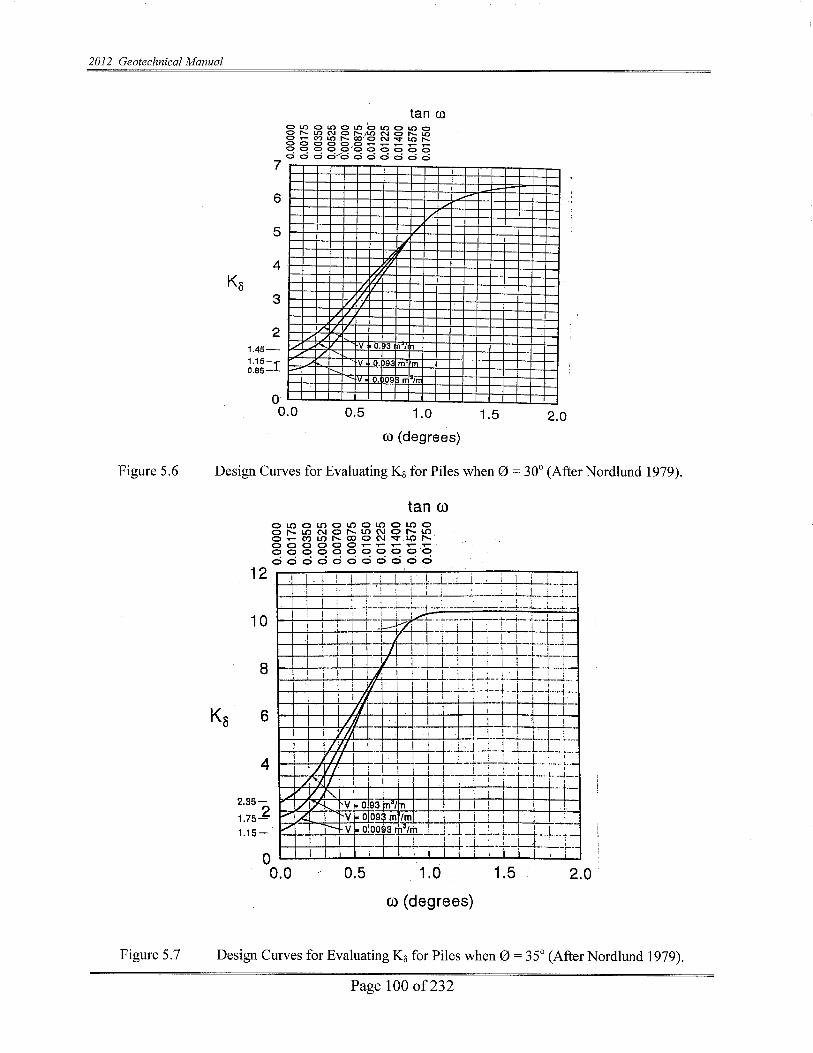


2012 Geotechnical Manual
Page 102 of 232
5.4.4 SKIN FRICTION RESISTANCE IN COHESIVE SOILS
The skin friction resistance for piles which are driven into cohesive soils is frequently larger than eighty (80%) or ninety (90%) percent of the total bearing capacity. Therefore, for such piles, it is extremely important that the skin friction resistance be estimated accurately. Design methods for piles in cohesive soils are in some cases of doubtful reliability. This is particularly true for the load capacity of friction piles in clays of medium to high shear strength (Cu > 100 kN/m2 (2,000 lb/sq ft). The frictional resistance is the average friction of adhesion multiplied by the surface area of the pile. For estimation of pile quantities, skin friction may be calculated as:
Equation (5.9)
where: fs = average unit skin friction or adhesion in tsf (KN/m2) P = perimeter of the pile (in ft.) L = embedded length of the pile (in ft.) The shearing stress between the pile and soil at failure is usually termed the "adhesion" (ca). The average nominal unit skin friction (fs) in homogeneous saturated clay, is expressed by:
Equation (5.10)
In this application, ∝ equals the empirical adhesion coefficient for reduction of average undrained shear strength (cu) of undisturbed clay within the embedded length of the pile. This method is known as the "Tomlinson Method" or the "∝ Method". The coefficient ∝ depends on the nature and strength of the clay, pile dimension, method of pile installation and time effects. The values of ∝ vary within wide limits and decrease rapidly with increasing shear strength. The values of ∝ can be obtained from Figure 5.12.
PLfQ ssf=
ccf uasα==

2012 Geotechnical Manual
Page 103 of 232
Figure 5.10 Determination of ∝ Coefficient and Variation of Bearing Capacity Factors with ∅

2012 Geotechnical Manual
Page 104 of 232
Figure 5.11 Relationship Between Maximum Unit Pile Point Resistance and Friction Angle for
Cohesionless Soils (After Meyerhof, 1976) Shaft resistance is calculated from the sum of the adhesion ca along the exterior of the two flanges plus the undrained shear strength of the soil, cu times the surface area of the two remaining sides of the box due to soil to soil shear along these two faces. Determining Skin Friction Resistance Using The "∝ Method"
STEP 1: Determine adhesion factor ∝ from Figure 5.12.
Enter Figure 5.12 with pile length in clay and undrained shear strength of soil (cu) in psf. Use appropriate curves for situations (a), (b), or (c) shown in the figure.
STEP 2: Compute ultimate unit skin friction resistance (fs). fs = ca (adhesión) = (∝) x (cu).
STEP 3: Compute total ultimate skin friction resistance.
Qs = (fs) x (As) where: As = Pile Surface Area

2012 Geotechnical Manual
Page 105 of 232
Figure 5.12 Adhesion Factors for Driven Piles In Clay--The Method (After Tomlinson, 1980)

2012 Geotechnical Manual
Page 106 of 232
5.4.5 END BEARING CAPACITY IN COHESIVE SOILS
The end bearing component of pile capacity (QP) can be determined by the general bearing capacity equation, using factors appropriate for deep foundations:
Equation 5.11
where: QP = nominal tip bearing capacity At = area of pile tip c = undrained shear strength (cohesion) in the vicinity of the tip γ = effective unit soil weight on the vicinity of the tip Pv = effective vertical stress (limiting overburden of 10-15 D) D = pile diameter or width Nc,Nq,Nγ = deep foundation bearing capacity factors (see Figure 5.13). NOTE: since D is usually small, the Nγ term is often neglected
Figure 5.13 Bearing Capacity Factors For Shallow And Deep Square Or Cylindrical Foundations
)2/1()( ttPP ADNPvNQcNcAQQ γγ++==

2012 Geotechnical Manual
Page 107 of 232
Figure 5.14 Relationship Between Undrained Shear Strength (c) and Penetration Resistance (N)
(Modified After Soweres, 1979)
For clay soils ( φ = 0, and assume Nq = 0), the end bearing becomes:
Equation (5.12) The undrained shear strength (c) of the soil near the sides of the pile and the tip of the pile should be determined in the laboratory. Figure 5.14 correlates the penetration resistance (N) to the undrained shear strength (c) based on textural classification. These are useful correlation for preliminary estimates only. A soil plug may form at the pile tip and the point bearing capacity may be calculated using the gross cross sectional area (ie. flange width times web depth for H-pile, etc.). This design assumption should be made based upon the subsurface information obtained during the Geotechnical Investigation performed for the project.
5.4.6 NOMINAL PILE CAPACITY IN COHESIVE SOILS
The nominal capacity of a pile (Qw), in clay can be determined by summing the total frictional resistance (Qs) and the maximum and bearing resistance (QP) as previously stated in Equation 5.4.
5.4.7 LOAD AND RESISTANCE FACTOR DESIGN POLICY FOR FOUNDATIONS
tcp AcNQ =

2012 Geotechnical Manual
Page 108 of 232
This document describes the LRFD design procedure Geotechnical Design for substructure foundations. Each new or replacement bridge foundation is to be designed in accordance with the AASHTO LRFD Bridge Design Specifications, 2007, 17
th Edition, including 2008 Interim
Revisions, and FHWA publication “LRFD for Highway Bridge Substructures and Earth Retaining Structures” FHWA-NHI-05-094 published in January 2006, if such Specification’ requirements are not shown in this document and/or in Indiana Design Manual Part VI. . This document shall replace the Sections of ASD theory of geotechnical design methods in Chapter 5 of the “INDOT Geotechnical Design Manual”.
The structural and the geotechnical engineers need to work together as a team to ensure that all LRFD structural and geotechnical limits for the foundations area met.
The INDOT Office of Geotechnical Engineering (OGE)/their Consultants will identify the geotechnical needs for the project based on the information made available to them by the INDOT Office of Structural Services or the Structural Engineer/Consultant (OSS) at the time of preliminary field check or pre-design meeting.
Shallow Foundation Design Steps:
The Structural engineer (SE) and the Geotechnical engineer (GE) need to work together as a team to ensure that all LRFD structural and geotechnical limits for the foundations area met. In order to recommend the use of shallow footings, the following design considerations should be performed and checked:
Step 1 Define subsurface conditions and any geometric constraints (GE)
Step 2 Determine depth of footing based on geotechnical bearing, scour, and frost protection considerations (GE)
Step 3 Estimate an array of footing sizes (GE)
Step 3.1 Determine applicable loads and load combinations (SE) Step 4 Factor loads for each combination (SE)
Step 5 Determine design soil properties and resistance factors (GE)
Tolerable settlement criteria shall be established by either empirical procedures or structural analyses, or by consideration of both (AASHTO 10.6.2.2). Tolerable movement criteria should be established early in the design process and communicated between the structural (OSE) and geotechnical designer. Step 6 Check global stability at the Service limit State (GE)
(The Structural designer need not investigate the global stability because it will be checked by the Geotechnical engineer.)
Step 7 Determine the nominal geotechnical bearing resistance at the Service Limit State
Step 8 Size footing at the Service I Limit State (For shallow foundations over rock refer to the next section)

2012 Geotechnical Manual
Page 109 of 232
Step 8.1 Compute Service Limit State bearing pressure and effective footing width
Check if bearing pressure and effective width satisfy criteria for vertical displacement? If Service Limit State criteria met, then go to Step 8.2. If not, revise footing size, configuration, or loads. Step 8.2 Compute Service Limit State Vertical and horizontal displacement
If Service Limit State criteria are met, go to Step 9. If not, revise footing size, configuration, or loads.
5.5 PILES IN TILL MATERIAL Glacial till is composed of unstratified materials that were deposited beneath glacial ice. Over one-half of Indiana is underlain by glacial till. Some layers in the glacial till are referred to as "hardpan" because of the difficulty experienced in driving, drilling, or digging through the material. The end bearing parameters (Nc & c) for glacial till should be large so that the nominal bearing capacity for driven piles will be obtained in the upper portion of the till. Piles should be driven only a few feet into glacial "hardpan". If the till is predominately non-cohesive, Thurman’s end bearing formula (Equation 5.8) should be used.
5.6 ADDITIONAL CONSIDERATIONS Following the analysis of static capacity of single piles, there are many other items requiring consideration (Schroeder, 1970) such as: 1) Capacity can change with time. 2) Load transfer can change with time from such causes as creep induced by new fill,
lowering the groundwater table, remolding of clay, etc. 3) Settlement of pile, etc. 4) Application to capacity and settlement of pile group 5) Negative skin friction, which is a bearing capacity problem induced by settlement. Some
causes are:
a) Placement of clay fill over sand where the fill drags the pile down during consolidation and lateral stresses also increase in sand.
b) Placement of fill over compressible clay where fill causes down drag and clay
also causes down drag due to consolidation effects.
c) Lowering of the groundwater table in compressible soils.

2012 Geotechnical Manual
Page 110 of 232
The method, assumptions, values, etc. presented are based on driven straight steel piles. Drilled or tapered piles and those made of other materials (timber, concrete, etc.) were not considered. If the pile tip rests in a stratum underlain by a weak soil, the nominal point resistance will be reduced. The nominal point resistance in the bearing stratum will be governed by the resistance to punching of the pile into the underlying weak soil.
5.7 PILES ON ROCK Approximately one-half of the area of Indiana has sedimentary rock near the ground surface (within fifty (50) feet or less). Deep foundations on rock are common where the soil layers are inadequate to support the service load of the structure. The items listed below should be considered for exploration and design for rock foundations. 1) Steel Encased Concrete (SEC) piles should not be considered when a deep foundation is
to be supported on shale or any other rock. H-piles driven to sound rock should be recommended. Piles on shale should be spaced at a minimum of 6 feet apart.
2) Pile tips should not be placed over shallow caves or other large voids. Geologic literature
for the area should be reviewed and a detailed field inspection should be performed in areas underlain by limestone.
3) Pile tips should not be placed on or stop in coal. 4) Rock Quality Designation (RQD) values can provide a qualitative assessment of rock
mass as shown in Table 5.2. The RQD is computed by summing the length of all pieces of core equal to or longer than four (4) inches, dividing by the total length of the coring run and multiplying by one-hundred per cent (100 %). Breaks caused by the coring operation should not be used in determining the RQD.
Table 5.2 Engineering Classification For In-Situ Rock Quality Using The Rock Quality
Designation (RQD).
RQD % Rock Mass Quality 90 – 100 Excellent 75 – 90 Good 50 – 75 Fair 25 – 50 Poor 0 – 25 Very Poor

2012 Geotechnical Manual
Page 111 of 232
5.8 SCOUR DEPTH The expected scour depth should be considered for every bridge structure over water, unless the scour is protected. The engineer should design the permanent pile capacity to mobilize the required soil resistance below the scour depth. The minimum pile tip elevation, for piers exposed to scour, will be ten (10) feet below the calculated scour depth. For end bents with spill-through slopes the minimum pile tip elevation will be at least equal to the flow line. The depth of scour (as shown on the plans) is dependent upon the hydrology of the channel, the alteration of the existing channel's cross-section by the proposed bridge structure and the engineering properties of the materials below the stream bed. The Geotechnical Engineer will use the scour depth in the engineering analysis. The scour depth for Q100 is generally considered in the engineering analysis.
5.9 PILE GROUP CAPACITY If Pile Group Capacity analysis is required on a given project, approval must be obtained from the INDOT Geotechnical Section prior to performing this work. If piles are driven into cohesive/compressible soil or in dense cohesionless material underlain by cohesive/compressible soil, then the load capacity of a pile group may be less than that of the sum of the individual piles. Also, settlement of the pile group is likely to be many times greater than that of an individual pile under the same load. Figure 5.15 for a single pile shows that only a small zone of soil around and below the pile is subjected to vertical stress. Figure 5.16 for a pile group shows that a considerable depth of soil around and below the group is stressed and settlement of the whole group may be large depending on the soil profile. The larger zone of heavily stressed soil for a pile group is the result of overlapping stress zones of individual piles in the group. The overlapping effect is illustrated in Figure 5.17. The group efficiency is defined as the ratio of the ultimate load capacity of a group to the sum of the individual ultimate pile load capacities.
Figure 5.15 Stressed Zone Under End Bearing Single Pile

2012 Geotechnical Manual
Page 112 of 232
Figure 5.16 Stressed Zone Under End Bearing Pile Group

2012 Geotechnical Manual
Page 113 of 232
Figure 5.17 Overlapping Stressed Soil Areas For A Pile Group

2012 Geotechnical Manual
Page 114 of 232
5.10 PILE GROUP CAPACITY IN COHESIONLESS SOILS In cohesionless soils, the nominal group load capacity of driven piles with a center spacing of less than three pile diameters is greater than the sum of the nominal load of the single piles. The greater group capacity is due to the overlap of individual soil compaction zones near the pile which increases skin resistance. Piles in groups at spacing greater than three times the average pile diameter act as individual piles. The following are design recommendations for estimating group capacity in cohesionless soil: 1) The nominal group load in soil not underlain by a weak deposit should be taken as the
sum of the single pile capacities.
2) If a group founded in a firm bearing stratum of limited thickness is underlain by a weak deposit, the nominal group load is given by the smaller value of either:
a) the sum of the single pile capacities or,
b) by a block failure of an equivalent pier consisting of the pile group and enclosed
soil mass punching through the firm stratum into the underlying weak soil.
From a practical standpoint, block failure can only occur when the pile spacing is less than two pile diameters, which is rarely the case. The method shown for cohesive soils (in the next section) may be used to investigate the possibility of a block failure.
3) Piles in groups should not be installed at spacings less than three times the average pile
diameter.
5.11 PILE GROUP CAPACITY IN COHESIVE SOILS In the absence of negative skin friction, the group capacity in cohesive soil is usually governed by the sum of the single pile capacities with some reduction due to overlapping zones of shear deformation in the surrounding soil. The following are design recommendations for estimating group capacity in cohesive soils: 1) For pile groups driven in clays with undrained shear strengths of less than 2,000 psf and
for spacings of three times the average pile diameter, the group efficiency can be taken to be equal to seventy percent (70%). If the spacing is greater than six times the average pile diameter, then a group efficiency equal to one-hundred percent (100%) can be used. For additional details, please consult the current NHI and FHWA manuals on pile group capacity.
2) For pile groups in clays with undrained shear strength in excess of 2,000 psf, use a group
efficiency equal to one-hundred percent (100%).

2012 Geotechnical Manual
Page 115 of 232
3) Investigate the possibility of a block failure. Recommended method is described in the next section.
4) Piles should not be installed at spacings less than three times the average pile diameter in cohesive soils.
5.12 NOMINAL RESISTANCE AGAINST BLOCK FAILURE OF PILE GROUP IN COHESIVE SOIL
A pile group in cohesive soil is shown in Figure 5.18. The ultimate resistance of the pile group against a block failure is provided by the following expression:
Equation (5.13)
where:
Qn = Nominal resistance against block failure
Cu1 = Undrained shear strength of clay below pile tips
Cu2 = Average undrained shear strength of clay around the group
B = Width of group
L = Length of group
D = Length of piles
Figure 5.18 Pile Group in Cohesive Soil
)2 )( 2() 1 9( ucxLBxDxLxBxucxQn ++=

2012 Geotechnical Manual
Page 116 of 232
5.13 SETTLEMENT OF PILE GROUPS
Pile groups supported by cohesionless soils will produce only elastic (immediate) settlements. This means the settlements in cohesionless soils will occur immediately as the pile group is loaded. Pile groups supported by cohesive soils may produce both elastic (immediate) and consolidation (occurs over a time period) settlements. The elastic settlements will generally be the major amount for over-consolidated clays and consolidation settlements will generally be the major amount for normally consolidated clays. Methods for estimating settlement of pile groups are provided in the following sections. Methods for estimating single pile settlements are not provided because piles are usually installed in groups. 5.13.1 SETTLEMENT CAUSED BY ELASTIC COMPRESSION OF PILE MATERIAL
DUE TO IMPOSED AXIAL LOAD
The methods discussed in the following sections do not include the settlement caused by elastic compression of pile material due to the imposed axial load. However, this compression can be computed by the following equation:
Equation (5.14)
where: δ Elastic compression of the pile material (usually quite small and is usually
neglected in design) P = Axial load in pile L = Length of pile A = Pile cross sectional area E = Modulus of Elasticity of pile material {E for steel piles = 206843 MPa (30,000,000
psi) and E for concrete piles = 20684 MPa (3,000,000 psi)}.
NOTE: Because the elastic compression of the pile is usually very small, it is often neglected.
5.13.2 IMMEDIATE SETTLEMENTS OF PILE GROUPS IN COHESIONLESS SOILS
Meyerhof (1976) recommended that the settlement of a pile group in a homogeneous sand deposit not underlain by a more compressible soil at a greater depth may be conservatively estimated by the following equation:
EA x L x P =δ

2012 Geotechnical Manual
Page 117 of 232
2p (B)1/2 I S = Equation (5.15a) (English) N' or 95p (B)1/2 I S = Equation (5.15a) (Metric) N' For silty sand use the following equation: 4p (B)1/2 I S = Equation (5.15b) (English) N'
or 190p (B)1/2 I S = Equation (5.15b) (Metric) N' where: S = estimated total settlement in mm (inches) B = the width of pile group in meter (feet) p = the foundation pressure in kN/m2 (tons per square foot) equal to design
load to be applied to the pile group divided by the group area N' = the average corrected SPT resistance (Figure 1) in blows per 0.3 m (foot)
within a depth equal to B below the pile tips I = influence factor for group embedment = 1 - D / (8 B) > 0.5 D = pile embedment depth, in meter (feet)
5.13.3 SETTLEMENT OF PILE GROUPS IN COHESIVE SOILS
A method proposed by Terzaghi and Peck, and confirmed by limited field observations, is recommended for the evaluation of the consolidation settlement of pile groups in cohesive soil. The load carried by the pile group is assumed to be transferred to the soil through a theoretical footing located at 1/3 the pile length up from the pile point (Figure 5.19). The load is assumed to spread within the frustum of a pyramid of side slopes at thirty degrees (30o) and to cause uniform additional vertical pressure at lower levels, the

2012 Geotechnical Manual
Page 118 of 232
pressure at any level being equal to the load carried by the group divided by the cross-sectional area of the base of the frustum at that level. This method can be used for vertical or batter pile groups.
The consolidation settlement of cohesive soil is usually computed on the basis of laboratory tests. The relationships of the compression index (Cc) to void ratio e and pressure are shown in Figure 5.20 which is plotted from consolidation test results. For loadings less than the preconsolidation pressure (pc) settlement is computed using a value of the compression index representing recompression (Ccr). For loadings greater than the preconsolidation pressure, settlement is computed using the compression index (Cc).
Figure 5.19 Stress Distribution Beneath Pile Group in Clay Using Theoretical Footing Concept (After Canadian Geotechnical Society, 1978)

2012 Geotechnical Manual
Page 119 of 232
Figure 5.20 The e-log-p Relationship (Modified from Canadian Geotechnical Society, 1978)
The following settlement equation is used for computing consolidation settlement:
S = H [ (Ccr / (1 + eo )) log (pc / po) + ((Cc / (1 + eo)) log ((Po + ∆P) / Pc)] Equation 5.16 where: S = total settlement H = original thickness of stratum Ccr = recompression index

2012 Geotechnical Manual
Page 120 of 232
eo = initial void ratio po = average initial effective pressure pc = estimated preconsolidation pressure Cc = compression index ∆p = the average change in pressure in compressible stratum considered
Procedure for Estimating Pile Group Settlement in Cohesive Soil
STEP 1: Determine Load Imposed on the Soil by Pile Group
1) Use the method shown in Figure 5.19 to determine the depth at which the
additional imposed load by the pile group is less than ten percent (10%) of existing effective overburden pressure at that depth. This will provide the total thickness of cohesive soil layer to be used in performing settlement computations. Use design load to be applied to the pile group. Do not use ultimate pile group capacity for settlement computations.
2) Divide the cohesive soil layer determined in 1) above into several thinner layers
1.5 to 3.0 m (five to ten feet) thick. The layer thickness H is the thickness of each layer.
3) Determine the existing effective overburden pressure (po) at midpoint of each
layer.
4) Determine the imposed pressure (p) at midpoint of each layer by using the method shown in Figure 5.19.
STEP 2: Determine Consolidation Test Parameters
1) Plot results of consolidation test (Figure 5.20) 2) Determine pc, eo, Ccr and Cc from the plotted data.
STEP 3: Compute Settlements
1) By using the settlement equation, compute settlement of each layer.
2) Summation of settlements of all layers will provide the total estimated settlement
for the pile group.

2012 Geotechnical Manual
Page 121 of 232
5.14 NEGATIVE SKIN FRICTION When a soil deposit, through which piles are installed, undergoes consolidation, the resulting downward movement of the soil around piles induces "downdrag" forces on the piles. These "downdrag" forces are also called negative skin friction. Negative skin friction is the reverse of the usual positive skin friction developed along the pile surface. This force increases the pile axial load and can be especially significant on long piles driven through compressible soils, and must be considered in pile design. Batter piles should be avoided in negative skin friction situations because of the additional bending forces imposed on the piles, which can result in the pile breaking. Settlement computations should be performed if necessary to determine the amount of settlement the soil surrounding the piles is expected to undergo after the piles are installed. The amount of relative settlement between soils and pile that is necessary to fully mobilize negative skin friction is approximately 0.5 inches. At that movement the maximum value of negative skin friction is equal to the soil adhesion or friction resistance. The negative skin friction can not exceed these values because slip of the soil along the pile occurs at this value. It is particularly important in the design of friction piles to determine the depth below which the pile will be unaffected by negative skin friction. Only below that depth can positive skin friction forces provide support to resist vertical loads. Figure 5.21 shows two situations where negative skin friction may occur. Situation (B) is the most common. Since negative skin friction is similar to positive skin friction (except that the direction of force is opposite), previously discussed methods can be used for computing pile skin friction.
Figure 5.21: Negative Skin Friction Situations

2012 Geotechnical Manual
Page 122 of 232
5.15 LATERAL SQUEEZE OF FOUNDATION SOIL Bridge abutments supported on piles driven through soft cohesive, or compressible, soils may tilt forward or backward depending on the geometry of the backfill and the abutment (Figure 5.22). If the horizontal movement is large, it may cause damage to structures. The unbalanced fill loads shown in Figure 5.22 displace the soil laterally. The lateral displacement may bend the piles, causing the abutment to tilt toward or away from the fill. The following rules of thumb are recommended for determining whether lateral squeeze or tilting will occur, and estimating the magnitude of horizontal movement involved:
5.15.1 DETERMINING LATERAL SQUEEZE.
Lateral squeeze or abutment tilting can occur if: (γfill x h fill) > (3 x un drained shear strength of soft soil).
5.15.2 MAGNITUDE OF HORIZONTAL MOVEMENT
If abutment tilting can occur, the magnitude of the horizontal movement can be estimated by the following formula: Horizontal Abutment Movement = 0.25 x Vertical Fill Settlement
5.15.3 SOLUTIONS TO PREVENT TILTING
The following solutions are possible means of eliminating tilting: 1) Get the fill settlement out before abutment piling is installed (best solution). 2) Provide expansion shoes large enough to accommodate movement. 3) Use steel H-piles to provide high tensile strength in flexure. 4) Excavate the compressible soils and replace with engineered fill.
5.16 PILE LATERAL LOADING
Horizontal loads and moments on a vertical pile are resisted by the stiffness of the pile and mobilization of resistance in the surrounding soil as the pile deflects. Following is a description of the parameters used in the determination of lateral load capacity of piles. Parameters Effecting Lateral Load Capacity of Piles Three types of parameters have significant effects on the lateral load capacity of piles. These three types of parameters are as follows: Soil Parameters 1) Soil type and physical properties such as shear strength, friction angle, density, and moisture
content.

2012 Geotechnical Manual
Page 123 of 232
2) Coefficient of horizontal subgrade reaction (kg/m3) or (pci). This coefficient is defined as the ratio between a horizontal pressure per unit area of vertical surface (kN/m2) or (psi) and the corresponding horizontal displacement (m) or (in). For a given deformation, the greater the coefficient, the greater is the lateral load capacity.
Pile Parameters 1) Physical properties such as shape, material, and dimensions. 2) Pile head conditions such as free head or fixed head. 3) Method of placement such as jetting or driving.
4) Group action. Load Parameters 1) Type of loading such as static (continuous) or dynamic (cyclic). 2) Eccentricity.
Figure 5.22: Abutment Tilting Due To Lateral Squeeze
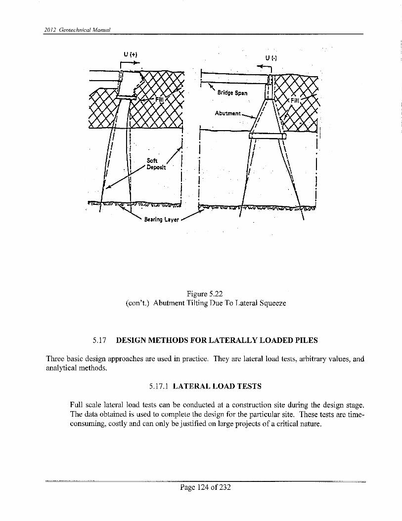

2012 Geotechnical Manual
Page 125 of 232
Table 5.3. Prescription Values For Allowable Lateral Loads On Vertical Piles (After New York, State Department of Transportation, 1977).
SOURCE PILE TYPE DEFLECTION SERVICE LATERAL LOADS in (mm) lbs (kg)
NYSDOT TIMBER CONCRETE STEEL
--- --- ---
10,000 15,000 20.000
(4500) (6800) (9000)
NY CITY 1968 BLDG
CODE
ALL
3/8 (10)
2,000
(900)
TENG ALL 1/4 (6.5) SOFT 1,000
CLAYS: (450)
FEAGIN
TIMBER TIMBER CONCRETE CONCRETE
1/4 (6.5) 1/2 (12.5) 1/4 (6.5)
1/2 (12.5)
9,000 14,000 12,000 17,000
(4100) (6300) (5400) (7700)
McNULTY
in (mm) 12 (300) TIMBER*(FREE) 12 (300) TIMBER (FIXED) 16 (400) TIMBER (FREE) 16 (400) TIMBER (FIXED)
1/4 (6.5)
1/4 (6.5)
1/4 (6.5)
1/4 (6.5)
MEDIUM SAND 1,500 (680)
5,000
(2,250)
7,000 (3,200)
7,000
(3,200)
FINE SAND 1,500 (680)
4,500
(2,000)
5,500 (2,500)
5,500
(2,500)
MEDIUM CLAY 1,500 (680)
4,000
(1,800)
5,000 (2,250)
5,000
(2,250) *SAFETY FACTOR OF 3 INCLUDED
5.17.2 ARBITRARY (PRESCRIPTION) VALUES
Arbitrary values of lateral load capacity are empirical. They do not consider all the site parameters and may lead to over-design or under-design. These values should be used only when little or no information exists regarding the specific site. The recommended values by several sources differ widely. The Canadian Foundation Engineering Manual (see list of references) states the following: "For cases of vertical piles subjected to small and transient horizontal loads it is common practice to assume that such piles can sustain horizontal loads up to 10% of the allowable vertical load (service limit, state load) without special analysis or design features."

2012 Geotechnical Manual
Page 126 of 232
5.17.3 ANALYTICAL METHODS
The analytical methods are based on theory and empirical data and permit the inclusion of various site parameters. Two available approaches are (1) Brom's method and (2) Wang and Reese's methods. Both approaches consider the pile to be analogous to a beam on an elastic foundation. Brom's method provides a relatively easy, hand calculation procedure to determine lateral loads and pile deflections at the ground surface. Brom's method ignores the axial load on the pile. Wang and Reese's more sophisticated methods include analysis by computer (COM-624 Program) and a non-dimensional method which does not require computer use. Wang and Reese's computer method permits the inclusion of more parameters and provides moment, shear, soil modulus, and soil resistance for the entire length of pile including moments and shears in the above ground sections.
It is recommended that for the design of major pile foundation projects, Wang and Reese's more sophisticated method be used. These methods are described in a FHWA manual on lateral load design (FHWA-IP-84-11). For small scale projects the use of Brom's method is recommended.
A step by step procedure showing the application of Brom's method, developed by the New York State Department of Transportation (1977), is provided below;
STEP 1: General Soil Type:
Determine the general soil type (i.e., cohesive or cohesionless) within the critical depth below the ground surface, approximately four or five pile diameters.
STEP 2: Coefficient of Horizontal Subgrade Reaction:
Determine the coefficient of horizontal subgrade reaction Kh within the critical depth from a cohesive soil:
Cohesive Soils: where:
qu = unconfined compressive strength in kN/m2 (psf) D = width of pile in meter (feet) η1 and η2 = empirical coefficients taken from Table 5.4.
Dqnn
hK u 80 21=

2012 Geotechnical Manual
Page 127 of 232
TABLE 5.4. Values of Coefficients n1 and n2 For Cohesive Soils.
UNCONFINED COMPRESSIVE STRENGTH
(qu) in kN/m2 (psf)
n1 < 50 (1000)
50 (1000) to 200 (4000) > 200 (4000)
0.32 0.36 0.40
PILE MATERIAL n2 STEEL
CONCRETE WOOD
1.00 1.15 1.30
TABLE 5.5. Values of Kh For Cohesionless Soils
SOIL Kh in kg/m3 (lbs/in3)
DENSITY ABOVE GROUND WATER BELOW GROUND WATER LOOSE
MEDIUM DENSE
200 x 103 (7) 830 x 103 (30)
1800 x 103 (65)
110 x 103 (4) 550 x 103 (20)
1100 x 103 (40)
STEP 3: Loading and Soil Conditions: Adjust Kh for loading and soil conditions: a) Cyclic loading (for earthquake loading) in cohesionless soil: 1) Kh = 1/2 Kh from Step 2 for medium to dense soil. 2) Kh = 1/4 Kh from Step 2 for loose soil. b) Static loads resulting from soil creep (cohesive soils): 1) Soft and very soft normally consolidated clays: Kh = (1/3 to 1/6)
Kh from Step 2. 2) Stiff to very stiff clays. Kh = (1/4 to 1/2) Kh from Step 2. STEP 4: Pile Parameter: Determine the pile parameter: a) Modulus of elasticity E (kN/m2) or (psi).
b) Moment of inertia I (m4) or (in4). c) Section modulus S about an axis perpendicular to the load plane (m3) or (in3).

2012 Geotechnical Manual
Page 128 of 232
d) Yield stress of pile material fy (kN/m2) or (psi) for steel or ultimate compression strength fc (kN/m2) or (psi) for concrete.
e) Embedded pile length L (m) or (in). f) Diameter or width D (m) or (in). g) Eccentricity of applied load e for free-headed pile -- i.e., vertical
distance between ground surface and lateral load, (m) or (in). h) Dimensionless shape factor Cs (steel piles only): 1) Use 1.3 for piles with circular cross-section 2) Use 1.1 for H-section piles when the applied lateral load is in the
direction of the pile's maximum resisting moment (normal to pile flanges).
3) Use 1.5 for H-section piles when the applied lateral load is in the direction of pile's minimum resisting moment (parallel to pile flanges).
i) Myield, the resisting moment of the pile = Cs fy S (M-kg) or (in lb) (for steel piles).
Myield = f´cs (m-Kg) or (in lb) for concrete piles.
STEP 5: Factor β or n: Determine factor β or n: a) for cohesive soil, or b) for cohesionless soil. STEP 6: The Dimensionless Length Factor: Determine the dimensionless length factor: a) β L for cohesive soil, or b) η L for cohesionless soil. STEP 7: Determine if the Pile is Long or Short: a) Cohesive soil 1) βL > 2.25 (long pile) 2) βL < 2.25 (short pile) NOTE: It is suggested that for βL values between 2.0 and 2.5, both long and short pile
criteria should be considered in Step 9. Use the smaller value. b) Cohesionless soil
1) ηL > 4.0 (long pile)
4 4/ EIDKh=β
5 / EIKn h=

2012 Geotechnical Manual
Page 129 of 232
2) ηL < 2.0 (short pile) 3) 2.0 < ηL < 4.0 (intermediate pile)
STEP 8: Other Soil Parameters: Determine other soil parameters:
1) Rankine passive pressure coefficient for cohesionless soil, Kp = tan2 (45 + φ/2) where φ = angle of internal friction.
2) Average effective soil unit weight over embedded length of pile γ (kg/m3) or (pcf).
3) Cohesion, Cu = one-half unconfined compressive strength, (qu/2) (kN/m2) or (psi).
STEP 9: Nominal (Failure) Load for a Single Pile: Determine the nominal (failure) load Pu for a single pile: 1) Short Free or Fixed-Headed Pile in Cohesive Soil: Using L/D (and e/D for the free-headed case), enter Figure 5.24 select
the corresponding value of Pu / Cu D2, and solve for Pu (kg) or (lb.). 2) Long Free or Fixed-Headed Pile in Cohesive Soil: Using Myield /Cu D3 (and e/D for the free-headed case), enter Figure
5.25, select the corresponding value of Pu/Cu D2, and solve for Pu (kg) or (lb.).
3) Short Free or Fixed-Headed Pile (Cohesionless Soil): Using L/D (and e/L for the free-headed case), enter Figure 5.26, select
the corresponding value of Pu/KpD3γ and solve for Pu (kg) or (lb.). 4) Long Free or Fixed-Headed Pile (Cohesionless Soil): Using Myield /D4γKp, (and e/D for the free-headed case), enter Figure
5.27, select the corresponding value of Pu/KpD3γ and solve for Pu (kg) or (lb.).
5) Intermediate Free/Fixed-Headed Pile (Cohesionless Soil): Calculate Pu for both a short pile (step 9-3) and a long pile (step 9-4)
and use the smaller value. STEP 10: Maximum Service Limit State Load

2012 Geotechnical Manual
Page 130 of 232
Calculate the maximum allowable working load for a single pile Pm from the nominal load Pu determined in Step 9.1 (this is shown in Figure 5.27)
Pu Pm = (kg) or (lb.) 2.5 STEP 11: Service Load for a Single Pile for a given Deflection Calculate the service load for a single pile Pa corresponding to a given
design deflection (y), at the ground surface or the deflection, corresponding to a given design load. If Pa and y are not given, substitute the value of Pm (kg) or (lb) (from Step 10) for Pa in the following cases and solve for Ym (m) or (in.):
1) Free or Fixed-Headed Pile in Cohesionless Soil: Using βL (and e/L for the free-headed case), enter Figure 5.30 select
the corresponding value of γKhDL/Pa, and solve for Pa (kg) or (lb). From Pa you can get y (m) or (in.).
2) Free or Fixed-Headed Pile in Cohesive Soil: Using ηL (and e/L for the free-headed case), enter Figure 5.23, select
the corresponding value of γ (E I)3/5 Kh2/5/Pa L, solve for Pa (kg) or (lb).
From Pa you can get y (m) or (in.). STEP 12: If Pa > Pm,use Pm and calculate Ym (Step 11). If Pa < Pm, use Pa and Y. If Pa and Y are not given, use Pm and Ym. STEP 13: Reduce the service load selected in Step 12 to account for:
1) Group effects as determined by pile spacing Z in the direction of load (see Figure 5.30).
2) Method of installation: For jetted piles use 0.75 of the value from Step
13-1). For driven piles use no additional reduction. STEP 14: The total lateral load capacity of the pile group equals the adjusted
service load per pile from Step 13-2) times the number of piles. The deflection of the pile group is the value selected in Step 12. It should be noted that no provision has been made to include the lateral resistance offered by the soil surrounding an embedded pile cap.

2012 Geotechnical Manual
Page 131 of 232
Figure 5.23 Group Effects As Determined By Pile Spacing Z In The Direction Of Load:
Special Note Inspection of Figures 5.25 and 5.26 for cohesionless soils indicates that the nominal load Pu is directly proportional to the effective soil unit weight. As a result, the ultimate load for short piles in submerged cohesionless soils will be about 50 percent of the value for the same soil in a dry state. For long piles, the reduction in Pu is somewhat less than 50 percent due to the partially offsetting effect that the reduction in γ has on the dimensionless yield factor. In addition to these considerations, it should be noted that the coefficient of horizontal subgrade reaction Kh is less for the submerged case (Table 5.5) and thus the deflection will be greater than for the dry state.
Figure 5.24 Nominal Lateral Load Capacity of Short Piles in Cohesive Soils
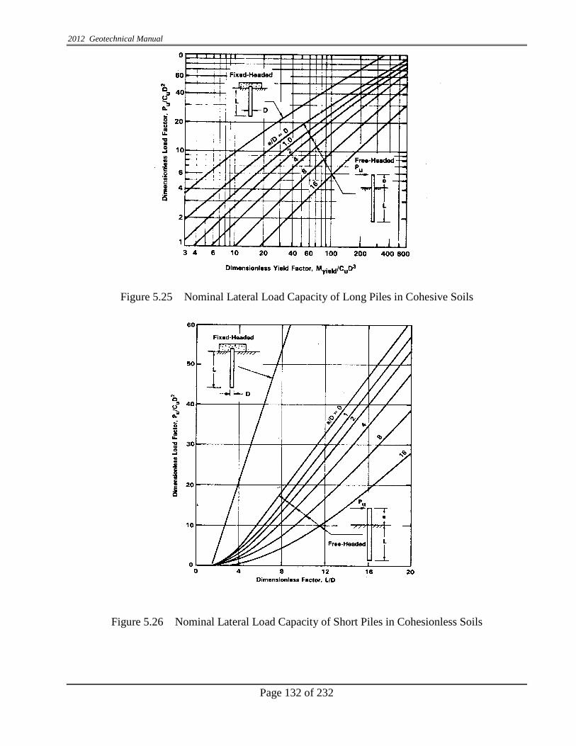
2012 Geotechnical Manual
Page 132 of 232
Figure 5.25 Nominal Lateral Load Capacity of Long Piles in Cohesive Soils
Figure 5.26 Nominal Lateral Load Capacity of Short Piles in Cohesionless Soils

2012 Geotechnical Manual
Page 133 of 232
. Figure 5.27 Nominal Lateral Load Capacity of Long Piles In Cohesionless Soils
Deflection y (M) or (N)
Figure 5.28 Relationship Between Load and Deflection

2012 Geotechnical Manual
Page 134 of 232
Figure 5.29 Lateral Deflections, At Ground Surface Of Piles in Cohesive Soils
Figure 5.30: Lateral Deflections, at Ground Surface of Piles in Cohesionless Soils


2012 Geotechnical Manual
Page 137 of 232
overburden soils be neglected. The cored hole diameter could be increased to accommodate for the required uplift resistance.
In the extreme load case, a resistance factor (ø) of 0.8 shall be considered for uplift resistance of piles and shafts. The resistance factor shall be provided in the geotechnical recommendations. For evaluating uplift, the geotechnical engineer shall provide the nominal (unfactored) unit side resistance, qs, per foot of the pile length. The structural designer shall include the design unfactored and factored uplift loads and a minimum tip elevation (indicating whether compression or uplift controls) on the Foundation Review form and on the contract plans. The designer should also consider geotechnical losses due to scour and liquefaction if applicable. Soils in liquefiable zones shall not be used for uplift resistance.
5.18.3 Seismic Slope Stability of Embankments (Geotechnical Memorandum 2010-05)
The following procedure as taken from NCHRP Report 611 shall be followed to check for Seismic slope stability: Step 1: Complete an assessment of Static Slope Stability. The resistance factors or factors
of safety shall be as required:
Min. Factor of Safety Max. Resistance Factors Roadway Embankments 1.3 0.75 Approach Embankments at Structures 1.5 0.65
Step 2: Determine Slope Aspect and Site Specific Seismic Coefficients, AS, SDS, and SD1
as per AASHTO
Step 3: Check if liquefaction potential exist at the approach embankments as described in Geotechnical Design Memo #2. If Yes – Mitigation is required. After mitigation is addressed check the criterion in Step 4.
For other roadway embankments if Step 1 is satisfied, and Step 2 determinations
are done, proceed to Step 4. Step 4: Check the no-analyses cut off criteria below:
Slope Angle AS Action 3H:1V <0.3 No analysis required
2.5H:1V <0.25 No analysis required 2H:1V <0.2 No analysis required


2012 Geotechnical Manual
Page 139 of 232
a) Sum of all vertical components of loads, ΣV. b) Sum of all horizontal components of loads ΣH. c) Sum of all moments of all vertical and horizontal forces at the toe.
∑Mv and ∑Mh
a) V
MMx hv
∑∑−∑
=
For other types of retaining walls use AASHTO LRFD guidelines.
b) Eccentricity of resultant load at foundation:
Use AASHTO LRFD guidelines.
c) Factored Bearing Capacity Use AASHTO LRFD guidelines.
d) Sliding – Use AASHTO LRFD guidelines.
e) Overturning – Use AASHTO LRFD guidelines. In case settlement is anticipated within the foundation influence zone due to the presence of soft soil, settlement analysis should be performed. Based on the laboratory test results a plot of total estimated settlement vs time, assuming most likely drainage conditions, should be presented for a specific section (cross sections should be provided).
2) Pile And Drilled-In Pier Retaining Structures:
Analysis of these types of structures takes into account • Lateral loads on structures • Depth of embedment for stability • Strain limits of the structural elements and • Soil and/rock pressure against structures.
3) Pile And Drilled-In-Pier Retaining Structures With Tie-Back System:
In addition to the factors described in part (b) above this analysis also includes the capacity of tie backs; the penetration required for stability, the spacing of tie backs and other design parameters. The distance and inclination of tie backs from the top of drilled pier and the amount of maximum movement is determined for each pier.

2012 Geotechnical Manual
Page 140 of 232
5.20 SEEPAGE ANALYSIS AND DRAINAGE FILTER REQUIREMENTS Seepage analysis is conducted at specific sections to estimate the quantity of seepage through and/or underneath the embankment, etc. Stability against piping and any other related analysis are to be analyzed as a part of the seepage analysis. However, prior approval of INDOT must be obtained before performing the analysis. The Engineer shall furnish computations for estimated seepage, calculated factor of safety against piping and all necessary curves and sketches. For drainage filter requirements, the following criteria are followed: 1) To avoid head loss in the filter: (D15 filter ÷ D15 protected layer) > 4,, and the
permeability of the filter must be adequate for the drainage system. 2) To avoid movement of particles from the protected layer:
(D15 filter ÷ D85 protected layer) < 5 (D50 filter ÷ D50 protected layer) < 25, and (D15 filter ÷ D15 protected layer) < 20: For a very uniform protected layer: (Cu > 1.5): (D15 filter ÷D85 protected layer) may be increased to 6. For a broadly graded base material (Cu > 4): (D15 filter ÷ D15 protected layer) may be increased to 40. NOTE: Cu = (D60 ÷ D10) = coefficient of uniformity.
3) To avoid movement of the filter into the drain pipe perforation or joints:
(D85 filter ÷ slot width) > (1.2 to 1.4) (D85 filter ÷ hole diameter) > (1.0 to 1.2)
4) To avoid segregation, the filter should contain no particle size larger than 3". 5) To avoid internal movement of fines, the filter should have no more than 5% passing
0.075 mm (No. 200 ) sieve. When the above criteria cannot be satisfied without using a multifilter media, the use of a suitable geosynthetic fabric can be included with a granular material. In this application, the fabric may be used to wrap the pipe to satisfy the opening requirements, or to line the trench to protect against the movement of fines into the collector.

2012 Geotechnical Manual
Page 141 of 232
5.21 GEOSYNTHETIC REINFORCEMENT The development of geosynthetics offers a range of new products for providing: 1) tensile characteristics to soils, 2) separation of different particle size materials; 3) filtration to allow movement of water without movement of soil fines; 4) a retaining system; and 5) serving more than a single purpose by employing the products in combination, if necessary. In most cases, geosynthetics (geotextiles or geogrid) are used to provide these benefits. However, metal reinforcement has been extensively used in MSE walls. The use of geosynthetics may expedite construction, enhance stability, and realize economic advantages that do not occur with soil-aggregate systems. Subgrade Reinforcement: The supporting capacity of subgrade varies widely due to different kind of subgrade soils generally encountered including cohesive and non-cohesive nature. It is very important not to over stress the subgrade for the stability of the pavement. Reinforcement is a very effective option for enhancing the bearing strength of a subgrade. Geosynthetic reinforcement does the following: 1) Improves tensile strength of subgrade. 2) Spreads the loads in wider area. 3) Generally reduce the thickness of the granular material (stone) layer above the subgrade. 4) Separates fines and aggregate at interface or prevents intrusion of aggregate into soft
subgrade. 5) Reduces rutting of the pavement. Embankment Reinforcement Embankments are constructed using a wide range of soil materials. Geosynthetic reinforcement improves the following:
• Increases tensile strength of fill material. • Increases FOS or enables us to provide steeper slopes.
For embankments more than 50' (15 m) high, a stability analysis should be performed. Reinforcement may be needed to satisfy stability requirements. This may also be necessary with lower strength soils, or steeper slopes, even when the embankment is not so tall.

2012 Geotechnical Manual
Page 142 of 232
Table 5.6 Recommended Factor of Safety (FOS) for Geotechnical Analyses
Type of Structure F.O.S.
Slope Stability Cut Fill
1.50 1.25
Global Stability Slope failure (Embankment)
1.25
Tie Back Pull-Out for Drilled Pier 2.00
Table No. 5.7 External Stability Resistance Factors for MSE Walls
STABILITY MODE
CONDITIONS RESISTANCE
FACTOR
Bearing Resistance
0.65
Sliding Resistance
1.00
Overall (Global) Stability
Where geotechnical parameters are well defined, and the slope does not support or
contain a structural element 0.75
Where geotechnical parameters are based on limited information, or the slope contains or
supports a structural element 0.65
(AASHTO TABLE 11.5.6-1)
Note: For other systems not covered here, use FHWA and AASHTO LRFD guidelines.

2012 Geotechnical Manual
Page 143 of 232
CHAPTER 6
DESIGN RECOMMENDATIONS
6.0 INTRODUCTION The design recommendation may include the description of the existing subgrade conditions, structures, embankment stability, cut slope, transitional grade (cut and fill), engineering characteristics of borrow soil, ground water conditions and should predict possible construction difficulties. Appropriate recommendations for stability and unsuitability of soil should be provided for the specific areas. This will ensure the proper design, plans and special provisions (if needed) for proper construction of the project. Alternate recommendations may be provided with cost benefit studies. It is advisable to maintain communication with INDOT Office of Geotechnical Services and the designers, if needed, regarding remedial measures during the development phases of the project. The geotechnical recommendations should be comprehensive, practical, cost effective and should be based on accepted engineering practices. Standard procedures and materials are preferable, unless conditions justify special construction techniques or materials. The design recommendations should include a recommended special provision for all job specific construction techniques, or materials. Construction and material inspection, testing and acceptance (according to INDOT practice and testing capability) must be addressed in the special provision.
6.1 PAVEMENT SUBGRADE Soil type and moisture content are the major factors influencing subgrade conditions (soil strength and deformation properties). Thus, moisture content is the primary controlling factor of the subgrade stability for a given soil. The field reconnaissance, pedological soil information, pavement maintenance history, in-situ density, moisture content, ground water data, drilling and laboratory data and scope of work will dictate the subgrade recommendations. Every effort shall be made to determine the water elevation. Analysis of the existing subgrade must delineate the area of concern during the construction. The recommendations shall be based on cost/benefit, local conditions, construction schedule or other considerations. Specific recommendations shall be based on previously described considerations. Various subgrade treatments are discussed in INDOT Specifications 207.04. Communication with designers, pavement design engineers, district construction engineer may lead to viable and economical recommendations. The geotechnical engineer in general shall follow these guidelines:
1) A resilient modules (Mr) test will be performed on each major project (for 800-ft. length
of pavement construction). The subgrade recommendations should be based upon a Mr test result on a predominant critical soil.

2012 Geotechnical Manual
Page 144 of 232
2) On any large project (for pavement construction > 2 miles) where subgrade soils differ significantly (equivalent CBR values with a difference > 1), two Mr values should be given if two subgrade areas clearly delineate.
3) Subgrade stabilization shall be considered for soil with equivalent CBR values less than 2.
Subgrade Under Rubblized Pavement. The analysis of subgrade under the existing pavement consists of evaluation of insitu moisture and density. The geotechnical engineer shall consider the proposal based on the existing subgrade conditions. They shall also anticipate its future performance during the design life. Unstable, unsuitable, or lower bearing values soils with constraints shall be delineated in subgrade recommendations and a resilient Modules (Mr) based on the existing conditions shall be recommended for pavement design. In general, the geotechnical engineer must present specific subgrade treatment recommendations to designers. The recommendation must give the estimated length (usually station to station), with type of treatment. The recommendations must allow the designers to calculate contract quantities. Every attempt shall be made to minimize the unknown during construction of the project. The recommendation shall be justifiable and should involve considerable judgment in order to interpret the field and laboratory data. The proposed subgrade shall be designed based on Mr. values obtained from laboratory test results. For the fill section, the Mr test shall be performed on the predominant soil type based on the best engineering judgment and evidence of geological information. Mr testing shall be similar to what is described in previous treatments.
6.2 UNSUITABLE SOILS
1) Cohesive soils with high clay content and high plasticity may exhibit relatively large volume changes, with changes in moisture content. Soils with maximum dry density of less than 100 pcf, or LL greater than 50 with PI greater than 25, should be considered unsuitable. If these soils are present in the subgrade, or must be used as embankment material, treatment may be warranted, and specific recommendations should be made. The recommendations may include limiting the use of unsuitable materials within the embankment, removal and replacement; or treatment with chemicals (such as, lime), flattening of the slope, etc.
2) Loess soils, found primarily in Southwest Indiana, sometimes must be used in
embankments, subgrades, and foundation soils. Specific recommendations should be made to deal with these soils. There are a variety of remedial measures that may be used to deal with unsuitable soils (peat, marl, trash fill, rubble fill, etc.). Each of these methods will require specific recommendations. Recommended methods must be cost-effective and constructible. Some of the methods commonly used are:

2012 Geotechnical Manual
Page 145 of 232
Table 6.1 Unstable Soil Problem/Solution Soil Reinforcement Pressure Grouting
Soil Bridging Stone Columns Excavation and Replacement Wick Drains
Displacement Lightweight Fill Surcharging Dynamic Compaction
Chemical Soil Modification Etc.
6.3 EMBANKMENTS
Embankment design recommendations should be cost effective and address short and long-term slope stability, and settlement issues. If any monitoring and/or stage construction is required, then specific recommendations (including Special Provisions) should be included in the Geotechnical Report. The embankment settlement must be tolerable, especially adjacent to rigid structures. Differential settlement is more of a concern than the total settlement. Special design methodology while using waste materials in construction such as coal ash, slag, and shredded tires, should be described in detail.
6.3.1 EMBANKMENT OVER PEAT/MARL
It is preferable to avoid peat/marl deposits, but there are times when they cannot be avoided. Embankments must be constructed on a stable foundation in these areas. This helps avoid serious problems, which may occur within a short time after completion. The manner in which this is accomplished, and the problems to overcome, depends largely on the type and depth of materials encountered. The presence of peat or marl may sometimes be determined by the surface appearance and vegetation cover. However, a detailed program of boring and sounding is required for accurate identification of peat/marl deposits. Natural peat/marl deposits often consist of several layers of peat, or combinations of organic and mineral deposits overlying stable mineral soil. While these upper layers may vary markedly in composition and exhibit a range in physical properties, they are entirely unsuitable as a foundation for highways. Therefore, it becomes necessary to treat these materials in such a manner that they do not cause detrimental settlement or failure of the embankments. When an embankment crosses peat/marl deposits (peat bogs) or swampy areas, stability and/or excessive settlement must be considered. A bridging layer will not be sufficient treatment. Extensive removal and replacement may be needed. Load balancing with lightweight fill is another option. Unsuitable soils may be removed from the embankment foundation, and replaced by material of higher shear strength. Normally, suitable borrow is satisfactory for replacement. In the case of a wet excavation, B-borrow must be placed to a height of 2 ft. (0.6 m) above

2012 Geotechnical Manual
Page 146 of 232
h h
h h
the water level observed at the time of placement. The remaining backfill may be accomplished with suitable borrow.
If it is economically feasible, removal should be performed to a point beyond the toe of the slope, a distance equal to the depth of removal as shown in Figure 6.1.
Fig. 6.1 Width of Removal And Replacement in Peat Bogs
Depending on the depth and thickness of peat/marl deposits four removal options are described below: 1) Total excavation method – This method can usually be used economically for
deposits less than 12 ft. (4 m) in depth. This method should only be recommended after considering: a) stability of the excavation slopes; b) the dewatering effect on adjacent pavement and surrounding structures, if needed; c) the difficulty and expense of dewatering; d) the difficulty of placing fill underwater; 5) etc.
2) Partial excavation – For a small embankment on a peat/marl deposit, where
settlement is the only concern, partial removal and replacement may be feasible. The geotechnical engineer must compute the depth to be removed, to reduce the settlement to a tolerable level. This must be based on laboratory tests. In general, the analysis will show that removing one half the peat does not remove half the settlement because the replacement material often weighs much more than the soil removed.
3) Displacement – If the peat and marl is too deep to be excavated, it may be possible
to remove by the displacement method. The theory of this procedure is to overload the weak material, to such an extent that it is displaced by a rolling surcharge and by backfill material. A forward relief trench, combined with a surcharge, creates the condition of unbalance, which causes displacement. Thus, the effectiveness of the treatment is directly related to the depth of the trench and the height of the surcharge. Failure to maintain adequate dimensions for the surcharge and trench is usually the cause of incomplete removal. An open trench is maintained to facilitate removal of
Embankment
Removal and Replacement Peat Peat

2012 Geotechnical Manual
Page 147 of 232
unsuitable soils as described in the INDOT Standard Specifications. Displacement of the peat should be verified by borings with continuous split-spoon sampling.
4) Load balancing with lightweight fill – When it is not feasible or economical to
remove the peat/marl deposits, it may be possible to “float” the new pavement. Heavier soils are excavated and replaced with lightweight fill in order to compensate for the weight of the new fill and pavement. Therefore, there is no increase in load to the peat. Light weight fills that are available are: a) cellular concrete at 20 to 50 Pcf, b) expanded shale, at 40 to 70 Pcf; c) expanded polystyrene (EPS) blocks at 1 to 4 Pcf, d) light weight slag 70 to 80 Pcf; e) shredded tires 40 to 60 Pcf, f) and other materials.
There are special techniques needed for some of these products, and environmental concerns with others. Before these products are recommended or used, the engineer should be familiar with the cost, special construction techniques, durability, and effects on future construction and maintenance to the roadway. When calculating the depth of excavation, the buoyant weight of the light weight fill and pavement should be considered, to prevent the pavement from floating during periods of high ground water and flooded ditches.
As with partial removal, partial load balancing may reduce settlement to a tolerable level, if the new load cannot be completely balanced. Lightweight fills do not stabilize or remove the peat; they merely “float” over the problem soils.
6.3.2 EMBANKMENT STABILITY OVER SOFT SOILS
Use of sand or wick drains can accelerate drainage, and speed consolidation and strength gain. Wick drains and sand drains have been successfully used by INDOT.
Many weak subsoils will tend to gain strength during the loading process, as consolidation occurs, and excess pore water pressure dissipates. A controlled rate of loading, or stage construction, may be utilized to take advantage of this strength gain. Maximum height of embankment for stage construction should be recommended in the geotechnical report. Proper instrumentation is desirable to monitor the state of stress in the soil during the loading period, to insure that loading does not proceed so rapidly as to cause a shear failure. If stage construction is recommended, special provisions must be included in the report. The slopes can be rendered safer by placing berms on the embankment. In no case, should the berms be narrower than 10 ft. (3 m), in order to provide for adequate maintenance by mechanical equipment. Geosynthetic products may also be used to stabilize embankment bases over soft and very soft materials. When the primary concern is stability rather than settlement, geotextiles and

2012 Geotechnical Manual
Page 148 of 232
geogrids can be used separately or together to reinforce the base of the embankment against lateral spread and failure. The design presented in the Geotechnical report must be analyzed for slope stability, bearing capacity, and settlement. Under special conditions, an area of weak soil may be bridged by a structure, and the concern for a stable embankment circumvented.
6.3.3 EMBANKMENT SETTLEMENT
Embankments constructed over compressible deposits experience settlements that vary in degree of severity and the length of time to reach equilibrium. Laboratory consolidation tests on undisturbed samples will give an estimate of the amount of settlement and the time required to achieve the settlement. The Consultant Geotechnical Engineer shall furnish computations for total estimated settlement (cross-section of up to three points if requested), a plot of percent total estimated settlement vs. time (at the point of maximum settlement unless otherwise approved) assuming the most likely drainage conditions, etc. The Geotechnical Report should describe the situation and present recommendations on various available treatments. The treatment methods should provide the designer with an opportunity to compare the economics of each, and to estimate the time required for achieving the greater part of the settlement, by each method. Each treatment method should be accompanied with backup data, to help the designer compare the alternatives.
Some of the corrective measures INDOT has used to mitigate settlement problems are:
1) Removal and replacement of the compressible soil. The economics of this method
have to be questioned, when the depth of removal exceeds 12 ft. (4 m.).
2) The use of instrumentation and time delays in bridge foundations and approach pavement construction, until an acceptable level of consolidation has taken place.
3) The use of sand or wick drains, mostly in conjunction with preloading, to accelerate settlement.
4) Preloading the site with a surcharge load.
5) Dynamic compaction. This consists of dropping a weight from a certain height to densify the upper 15 to 20 ft. (4.5 to 6 m) of loose, granular deposits.
The compressible deposit may be removed and replaced by a suitable material, if economically feasible. The replacement material placed should be a drainable, granular material placed to a height of 2 ft. (0.6 m) above seepage water in the excavation. The remainder may be constructed with suitable earth borrow. When settlement problems arise, the time of settlement can be substantially reduced through the construction of a drainage blanket. This blanket should consist of clean, drainable sand or granular material, (No. 8 or No. 53 stone) not less than 24 in. (600 mm) thick. The blanket is placed over the original ground surface and serves as a drainage platform for the embankment. The granular blanket must be day-lighted at the sides of the embankment, or effectively tapped, in order to provide free drainage. Settlement plates along stakes with slope indicators should I-465 south of East Washington St. Wick Drains

2012 Geotechnical Manual
Page 149 of 232
be installed for future monitoring. The drainage path for surplus moisture in consolidating deposits may also be shortened by the use of vertical sand drains or wick drains, to reduce the settlement time. A successful sand or wick drain operation requires a detailed subsurface analysis, design, and careful installation of the sand or wick drains. The detailed procedures should also consider the nature of the substrata and its influence on the success of the treatment. The rate of settlement depends upon the thickness and permeability of the consolidating layer, the character of the drainage pattern, and the pore water pressure. Thus, a surcharge can be used to speed up consolidation. However, care must be taken to assure the shear strength of the supporting soil is not exceeded; or a lateral squeeze may result.
6.4 EMBANKMENT REINFORCEMENT
Due to the high cost of additional R.O.W. and retaining wall systems, reinforced soil slopes (RSS) may be considered when there is insufficient R.O.W. for a normal embankment side slope. The reinforced soil slope must have both internal and external stability and tolerable settlement. Erosion should also be addressed. The engineer must analyze external stability and settlement. Also, the engineer should provide any design recommendations necessary to ensure that the RSS system is stable and that settlement is tolerable.
If the geotechnical engineer elects to perform the detailed reinforced soil slope design, complete design recommendations should be provided, including: 1) Slope angle. 2) Specifications for the geosynthetic material. 3) The geosynthetic embedment length. 4) Specific geosynthetic vertical locations and soil layer thicknesses. 5) Embankment properties, and compaction require 6) Slope surface treatment. A Special Provision should indicate the materials and construction techniques.
6.5 CUT SLOPES Frequently considerable amounts of cuts are encountered for roadway construction. Current practice utilizes a minimum FOS of 1.5 for cut slopes, based on laboratory testing of undisturbed samples. If the stability analysis is based on the field tests of split-spoon samples, the FOS should be 1.7 or greater.

2012 Geotechnical Manual
Page 150 of 232
The higher FOS required for backslopes (cutslopes), as compared to embankments, is based upon the knowledge that cut slopes may deteriorate as a result of natural drainage conditions. Cut slope stability may be improved by the following: 1) Flattening of Slopes 2) This can most effectively be accomplished by benching. Benches should be at least 10 ft. (3
m) wide [ideally 15 ft (4.5 m)] in order to provide for proper construction and maintenance. 3) Improvement of Drainage
Ground water seepage at the face of a cut slope, or a perched water table (due to a soil contact with a less permeable underlying layer) may result in sloughing, or other problems. Drainage cutoff trenches may be designed to intercept the seepage, and thus, render the slope face stable. Horizontal drainage system using geofabric should be considered as a remedial measure for the stability of slope. Under special conditions, stability may be provided by some erosion protection measures or by a properly designed retaining structure, which includes retaining walls, rock buttressed, bin walls, or sheeting walls.
Specific design recommendations must be provided to ensure cut slope stability, if the analysis shows an unacceptable FOS.
6.6 BRIDGE AND RETAINING STRUCTURES
Based on the findings of subsurface exploration and engineering analysis recommendations for the stability of structure are made. The factor of safety of various structures for geotechnical design are presented in Table 5.1. 1) Bridge Foundation:
In case of deep foundations like H-piles or steel encased piles, it should be analyzed at each pier location. Each pile should be analyzed to determine the embedment lengths for 56,77 and 98 T factored loads. In case of SEC/pipe piles 14 inch and 16 inch diameters should be considered. In most of the case for design load of higher than 70 T service load PDA (Pile Driving Analyses) tests should be recommended. Test piles are driven to 150% of the total service bearing capacity. The test pile is ordered 10 ft. (3 m) longer than the estimated design length. The production piles for the structure are ordered after a careful review of the test pile record and the foundation borings.
2) Retaining Walls: Based on the engineering analysis of retaining walls (as discussed in Chapter 5) following should be recommended.

2012 Geotechnical Manual
Page 151 of 232
a) Depth of foundation. b) Allowable bearing capacity of foundation steel. c) Shear strength parameter of friction angle of granular backfill. d) Shear strength parameter of foundation soil.
3) Pile and Drilled-In-Pier Retaining Structures (With and Without Tiebacks).
Based on engineering analysis recommendations should include the following. a) Allowable lateral load. b) Depth of embedment. c) Station limits of structural elements. d) In case of tiebacks, the capacity and spacing of the tiebacks. e) Other required design parameters, etc.
6.7 SPECIAL PROBLEMS
Special problems may require careful evaluation regarding their effect on the final improvement. One of the most common is active or abandoned mines. The presence of mines is reflected in local sinks or settlements of the ground surface. Equally important, though less frequent in Indiana, is the occurrence of karst topography. Karst topography consists of solution cavities and caverns in underlying limestone, which may also result in local sinks or settlements. Such situations should always be brought to the designer’s attention during the planning phase. At this phase, the design could be modified to correct the problem, or to provide for easier correction of future problems. Recommendation for transition cases (to cut or to fill) should be made for uniformly distribution of loads on subgrades.
The geotechnical engineer may not be able to present design solutions to every special problem in the Geotechnical Report. The Report, however, may be the only place where such geological hazards are brought to the attention of the designer.

2012 Geotechnical Manual
Page 152 of 232
CHAPTER 7
GEOTECHNICAL REPORT
7.0 GENERAL The geotechnical report shall be the presentation of all data obtained during the investigation which includes the office survey, field check, boring logs, past history of the location, all engineer’s analyses, and recommendations. The variability in soil properties and its behavior along the road way could make those tasks challenging. Therefore, it is prudent upon Engineers to base the design recommendation on a combination of soil engineering judgment, hard data, field reconnaissance, etc. that truly reflects soil behavior, and the geotechnical analyses acceptable to INDOT. Ten copies of the approved geotechnical report shall be submitted upon INDOT's request. A copy of all driller’s field logs will be required along with the first submittal of the report.
7.1 CONTENTS OF REPORT
1) EXECUTIVE SUMMARY: shall include a concise summary of the major recommendations (usually two pages or less).
2) GENERAL INFORMATION
a) The location of the project (including the beginning and ending stations), project identification and background, and the scope of proposed construction.
b) The date, month and year when the field investigation was performed.
c) A general description of the geology and soils encountered on the project, and a
description of the terrain, to include drainage, erosion patterns, high water elevation, flooding, and any other specific conditions which may be of value in the design of bridges, culverts and other structures.
4) Any other information which may be of value for the proper interpretation of the
field survey data. 3) EVALUATION OF THE SUBSURFACE CONDITIONS
This section of the report should include a thorough evaluation of the data collected in the field as well as in the laboratory. Summarize the findings, including ground water conditions, moisture content, soil types encountered, consistency and density, and any bedrock or unsuitable soils encountered on the project.
4) ENGINEERING ANALYSES Describe here any engineering analyses that were performed for the project and the reasons for the analyses. For each analysis, a complete description of the parameters used, locations,

2012 Geotechnical Manual
Page 153 of 232
and the specific boring information used in the development of the model for the analyses. The Consultant should specifically mention the area of the type of the problem, location of each model, boring logs used in each analysis, interpretation of the laboratory data, based on our findings, the problem areas should be identified, for each type of analysis. However, the actual data and the model should be included in the appendix of the report.
5) DETAILED GEOTECHNICAL RECOMMENDATIONS The project shall be described by areas of similar soils and terrain features or conditions
from the beginning of the project to the end. The soils of each area shall be generally described; specific problems or conditions shall be explained; and recommendations with the results of engineering analyses (where applicable) shall be made relative to any special embankment construction; cut slope recommendations in soil or rock; soil subgrade recommendations, subgrade removal, replacement, or treatment, some possible causes for the existing subgrade problems; removal of unsuitable soil; rock swell factors; drainage installations; the use of channel change materials, and/or any other factors affecting design or construction of the project. Any investigation of interchanges, S-lines and/or channel relocations shall also be a part of the report.
Whenever it is recommended to install field monitoring equipment and/or devices such as
piezometers, settlement plates, and stakes, toe stakes, etc., the recommendations should include the purpose and/or objective, proposed locations, an approximate schedule as to the frequency of readings, controls which can be used during construction to assure proper performance based on the design assumptions,
6) SITE LOCATIONS AND BORING LOGS
GPS Coordinates should be provided for each boring location. Logs of all borings (including structure) shall be included in the Appendix of the Report.
The logs shall be based on the field logs and laboratory test data. The logs shall contain all the information recorded on field logs as specified in Section 4.3, except the description of soil layers which shall include grain-size classification and AASHTO classification based on laboratory test data, and each soil layer shall be referenced to a laboratory sample number. A structure boring location plan view shall be included in the appendix of the Geotechnical Report.
7) TEST DATA The results of all laboratory tests on various samples shall be tabulated and included in the
Appendix of the Report. The tabulation shall identify each sample as to sample number, boring number, location and depth, and shall include all results obtained as described under Section 4.10. Separate tabulations shall be included for classification test results and strength test results. For construction of pavement subgrade evaluation form (as given in Appendix 14 (7.1), Subgrade Evaluation) should be completed for each boring.

2012 Geotechnical Manual
Page 154 of 232
8) ENGINEERING ANALYSIS
The work described herein shall include review and correlation of various test results as to embankment stability, material placement and other geotechnical engineering considerations. Sketches, assumptions, calculations, etc., (where applicable) of all final engineering analyses and recommendations done as discussed in Chapters 5 and 6 shall be included in the Appendix of the Report. The source of the analysis, the input and output data (properly labeled) shall be provided if computerized analysis methods are utilized. The Consultant Geotechnical Engineer shall also attend all field checks, conferences, etc., as requested by INDOT. Methods of analysis shall have prior approval.
9) REPORT SUBMITTAL At completion of the project submittal should consist of the following;
(a) Final Report should be in electronic form in ( PDF) The PDF of the report should be made
directly from the word (not from scanning). Scanning part is only allowed for hand written, notes and calculations. (b) gINT in INDOT format
(c) Hard copy of the report and (d) Itemized costs.

2012 Geotechnical Manual
Page 155 of 232
REFERENCES
1. AASHTO-T 88, “Determination of Grain Size Analysis of Soil”.
2. AASHTO T-89, “Determination of Liquid Limit of Soil”.
3. AASHTO T-90, “Determination of Plastic Limit of Soil”.
4. AASHTO T-100, “Determination of Specific Gravity of Soil”.
5. AASHTO M-145, “Determination of Classification of Soil”.
6. AASHTO T-193, “California Bearing Ratio Test”.
7. AASHTO T-203, “Hand Auger for Subsurface Determination”.
8. AASHTO T-207, “Shelby Tube Sampling of Soil”.
9. AASHTO T-208, “Determination of Unconfined Compressive Strength of Soil”.
10. AASHTO T-215, “Determination of Permeability of Soil”.
11. AASHTO T-216, “Determination of Consolidation Test”.
12. AASHTO T-265, “Determination of Moisture Content”.
13. AASHTO T-267, “Determination of LOI (Loss of Ignition)”.
14. AASHTO T-296, “Determination of Triaxial Testing” (UU).
15. AASHTO T-297, “Determination of Triaxial Testing” (CU).
16. AASHTO T-307, “Determination of Resilient Modulus”.
17. ASTM D-2434, “A Constant Head Test to Determine the Hydraulic Conductivity of Soil”.
18. ASTM D-2976, “Determination of Ph Values of Soil”
19. ASTM D-5084, “Flexible Wall Method to Determine the Hydraulic Conductivity of Fine Soils”.
20. Bowles, J.E., (1998) “Foundation Analysis and Design”, McGraw-Hill Book Company, Inc., New York.
21. Canadian Foundation Engineering Manual.
22. Das, B. M. (1988) “Principles of Foundation Engineering”.
23. Das, B. M. (1994) “Principles of Geotechnical Engineering”.
24. Malott ,Clyde A. (1922) Physiographic Map of Indiana
25. Driven 1.2 (1998) User’s Manual” Publication No. FHWA-SA-98-074
26. EM 1110-2-1906, “Determination of Unit Weight of Soil”, Engineer Manual of Soil Laboratory Test. U.S. Army Corps of Engineers.
27. FHWA Manual (COM 624 Program) of Piles Analysis (FHWA IP-84-11) (Uses Wang and Reese’s Method).
2012 Geotechnical Manual
Page 156 of 232
28. HFHWA-HI-88-009 Workshop Manual on Soils and Foundation, NHI Course No. 13212.
29. FHWA-HI-96-013 and FHWA-HI-97-014 Design and Construction of Driven Pile Foundations.
30. FHWA-Manual on “Design and Construction of Driven Pile Foundations”, DP-66-1, January 1996.
31. FHWA-RD-89-043 (1990) “Reinforced Soil Structures”.
32. FHWA-SA-96-071 (1998) “Mechanically Stabilized Earth Wall”.
33. Gray, Henry H. (1982) Map of Indiana Showing Topography of Bedrock Surfaces
34. Gray, Henry H. (1988) Map of Indiana Showing Thickness of Unconsolidated Deposits.
35. Gray, Henry H. (1989) Indiana Geological Survey Quaternary Geological Map of Indiana
36. INDOT Bridge Design Memorandum #213 (1992) for Seismic Design Criteria.
37. Meyerhof, G.G. (1976) “Bearing Capacity and Settlement of Pile Foundations”, Journal of Geotechnical Engineering Division ASCE Vol. 1.2 No. G13 Proc. Lafer 11962 pp 195 – 228.
38. MN DOT (1991) Weathering Nomenclature for Rocks.
39. Nordlund, R.L. (1963) “Bearing Capacity of Piles in Cohesionless Soils”, ASCE
40. Nordlund, R.L. (1979) “Point Bearing and Shaft Friction of Piles in Sand”, 5th Annual Fundamentals of Deep Foundation Design. University of Missouri Rolla.
41. NY DOT (1977) “Prescription Values of Allowable Lateral Loads on Vertical Piles”, (Uses Bron’s Method of Pile Analysis).
42. Peck, Hanson and Thornburn (1974) “Foundation Engineering”, John Wiley and Sons N,.Y. 2nd Edition.
43. Peck, R. P., et. al., (1953) “Foundation Engineering”, John Wiley & Sons, Inc., New York.
44. Folk, R. L. (1980) Petrology of Sedimentary Rocks.
45. Rendon-Herrero (1980) “Universal Compression Index Equation”, Journal of Geotechnical Engineering Vol. 106, GTII, 1979-1200.
46. Schroeder, J.A., (December 1980), “Static Design Procedures for Ultimate Capacity of Deep Foundations”, prepared for H. C. Nutting (in-house seminar), Cincinnati, OH
47. Skempton, A.W. and Bjerrum, L. (1957) “A Contribution to Settlement Analysis of Foundations in Clay Geo-technique”, London, England, U.K. V.7, P. 178.
48. Sowers, G.F., “Introductory Soils Mechanics and Foundations: Geotechnical Engineering”. MacMillan Publishing Company, Inc., New York, (1979).
49. Tomilson, M.J., (1970) “Some Effects of Pile Driving on Skin Friction”, Conference on Behavior of Piles, Institute of Civil Engineers, London, pp,. 57-66.

2012 Geotechnical Manual
Page 157 of 232
50. Tomilson, M.J. (1980) “Foundation Design and Construction”, Pitman Advanced Publishing, Boston, MA. 4th edition.
51. Tomilson, M.J. (1985) “Foundation Design and Construction”, Langman Scientific and Technical, Essex, England.
52. WEAP (1997) “Wave Equation Analysis for Pile Design”.
53. XSTABL (1995) “Version 5 Reference Manual Interactive Software Designs” Moscow, ID, USA

2012 Geotechnical Manual
Page 158 of 232
APPENDICES

2012 Geotechnical Manual
Page 159 of 232
Appendix 1 Application Guidelines to Become an Approved Geotechnical Consultant
Indiana Department of Transportation Materials and Tests Division
Submittal Date: ____________ In order to be considered for approval as an Indiana Department of Transportation Geotechnical Consultant, closely follow the guidelines as presented, answer all questions and submit all required documentation to the Chief Geotechnical Engineer.
General Information:
Name of Firm: Address:
E-mail Address: Webpage Address: Phone: Fax: Minority Owned: Woman Owned: Section 1 - Firm Experience:
Provide names of relevant road and bridge projects and include brief descriptions of the size and scope of work performed. Include a sample geotechnical report.
Section 2 - Engineering Staff
A. Principals in Charge: This should include the name of the individual(s) who is responsible for the final review of reports prior to submission. These individuals should have five years experience in geotechnical engineering and be registered PE’s in the State of Indiana. Include the name and title within the company, and a resume of each individual for consideration for approval.
B. Project Engineers: All other engineers within the firm who work on INDOT geotechnical reports must have the same experience and also be registered P.E.’s in the State of Indiana. Include the name and title within the company and a resume. They must receive prior approval from the Chief Geotechnical Engineer prior to submission of reports.
C. Staff Engineers: Individuals who are full time employees who perform the geotechnical engineering analysis and prepare the reports. Include the names and titles within the company as well as resumes.
Section 3 - Laboratory Facilities
A. Facilities All facilities must have the capabilities to perform required tests as described in the Geotechnical Manual, and must pass a one time pre-qualification inspection by INDOT representatives. An AMRL Laboratory Assessment for equipment and procedures and AMRL Proficiency Sample Program participation is mandatory. The initial INDOT inspection will also inspect for equipment compliance used in determining pH and LOI, high humidity storage facilities and literature availability.

2012 Geotechnical Manual
Page 160 of 232
B. Lab Equipment Requirements: 1. Apparatus required to test for Organic Content, Loss on Ignition
i. Oven: Capable of maintaining 230 degrees +/-9 degrees F (110 +/-5 degrees C). ii. Balance: Must meet AASHTO M231, Class C iii. Muffle Furnace: Maintains temperature of 883 +/-18degrees F (445 +/- 10 degrees C) and
must have a combustion chamber capable of accommodating the designated containers and samples.
iv. Crucibles: Porcelain or nickel crucibles of 30 to 50 ml capacity or Coors Porcelain evaporating dishes approximately 100 mm top diameter and lids for the crucibles.
v. Desiccator: Desiccator of sufficient size to accommodate samples. vi. Containers: Glass or plastic coated containers vii. Miscellaneous Supplies: Gloves, Tongs, Spatulas. viii. Surcharge Weights: As listed in Geotechnical Manual, (Exhibit C), must number 25
2. Apparatus required to test pH i. pH meter: list make and model ii. Balance: Must meet AASHTO M-231 requirements iii. Beakers: 100ml beakers
3. High Humidity Room: i. Moisture Room must be a minimum of 100 square feet ii. Must maintain temperatures of 68 to 72 degrees F., with an 85% relative humidity.
4. Must comply with the following AASHTO and/or ASTM laboratory methods: T 87, T 88, T 89, T 90, T 99, T 100, T 193, T 200, T 208, T 215, T 216, T 233, T 265, T 267, T 296, T 297, T 307, ASTM D 5084, and ASTM D 5333.
C. Literature Required – Volumes of Specifications
1. AASHTO: current volume 2. ASTM: current volume 3. INDOT: current volume 4. Thermometers: NIST traceable
Section 4 - Field Staff:
A. Drillers and Equipment Operators: Drillers who are full time employees and are experienced in all types of geotechnical drilling, sampling and instrument installation are required to operate drilling rigs on all projects. Certain types of geotechnical testing and instrument installation require at least one driller in the company to be a State of Indiana Licensed Well Driller.
B. Field supervisors: Field supervisors must be full time employees who are assigned to inspect geotechnical drilling operations, log borings, and make responsible engineering decisions in the field. Include the name and title within the company along with resumes.
C. Drill Rigs: Drill rigs must be owned by the company or leased. If leased, INDOT may require proof of lease agreement at any time for inspection. Drill rigs used are required to be equipped with automatic hammers, not catheads. All drilling is to be performed by the applicant company’s full time employees, not subcontracted drillers. List manufacturer and types of drilling equipment to be used, and if the drilling equipment is leased, the name of the company leased from should also be submitted.
Completed documentation or questions and comments about completion of the requirements should be addressed to the Manager, Office of Geotechnical Engineering, 120 S. Shortridge Road, Indianapolis, IN 46219, or call 317-610-7251.

2012 Geotechnical Manual
Page 161 of 232
Appendix 2 Department Policy
Indiana Department of Transportation Materials and Tests Division
Policy No. 13-6 January 3, 2005 Indiana Department of Transportation Policy for Approval of Geotechnical Consultants
1. Policy:
The Department will maintain a list of qualified geotechnical consultants and conduct approval evaluations of geotechnical consultants properly applying for such status. In order to be approved, consultants are required to satisfy the areas of service which includes the engineering staff, field supervision staff and equipment, and a certified laboratory. Therefore, applicants are to provide information concerning the qualifications of their engineering staff, field service operations, and laboratory services.
2. Requirements for Approval:
a. The geotechnical consultant applicant must file letters of intent to pursue approval with the Manager, Office of Geotechnical Engineering, of the Production Management.
b. The geotechnical applicant must follow the “Application Guidelines to become an Approved Geotechnical Consultant”, and include all sections in the order as requested. The information provided in the documentation will be reviewed by the Manager and a decision for preliminary approval will be determined.
c. If all information shows compliance with the requirements listed, the Chief Geotechnical Engineer shall provide a written recommendation for approval to the division of Production Management.
d. A preliminary approval letter will be sent subject to the on-site inspection of the consultant’s laboratory facility.
e. The INDOT lab inspector will contact the consultant to set up an on-site inspection. f. After the inspection, results will be reported to the Manager. If the lab is determined to be
compliant, final approval will be given and a copy of the Geotechnical Manual, sample drawings and other guidelines required to perform investigations on INDOT projects will be sent and your firm will be added to the approved list.
g. If deficiencies exist, the applicant will be contacted by the Manager to determine the measures necessary to correct the problem. INDOT will stop work on the request until the consultant has performed the corrective actions.
h. When the Manager is satisfied with the content of the request and upon a second inspection of the laboratory facilities, if needed, the Manager of Materials and Tests Division will again be asked to review the consultant.
i. The Manager will send the consultant a letter approving or disapproving the applicant’s request. If the letter is disapproval, the reason(s) will be given.

2012 Geotechnical Manual
Page 162 of 232
Appendix 3 (4.1) Boring Log Example

2012 Geotechnical Manual
Page 163 of 232
Appendix 4 (4.2) Grain Size Example
Boulders Gravel Sand Silt Clay Coarse Fine
Sample
Identification. Station / Offset / Line Dept, meters Elev. USCGS
RB-5 SS-3 2+300 3.0m Lt. "A" 1.2 - 1.7 258.8 + 258.1
Lab # Class Spec. Gravity pH %
Gravel %
Sand % Silt % Clay MC % LL PL PI
N/A Loam A-4(1)
# 4 # 10 # 40 # 200
0
10
20
30
40
50
60
70
80
90
100
0.001 0.01 0.1 1 10
Perc
ent F
iner
By
Wei
ght
Grain Size (mm)
Grian Size Analysis
Class 'C' Fly ash
loess
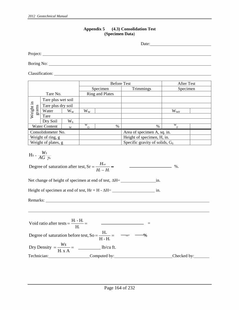
2012 Geotechnical Manual
Page 164 of 232
Appendix 5 (4.3) Consolidation Test (Specimen Data)
Date:
Project: Boring No: Classification:
Tare No.
Before Test After Test Specimen Trimmings Specimen
Ring and Plates
Wei
ght i
n gr
ams
Tare plus wet soil Tare plus dry soil Water WW WW WWF Tare Dry Soil WS
Water Content W W
O % % WF
Consolidometer No. Area of specimen A, sq. in. Weight of ring, g Height of specimen, H, in. Weight of plates, g Specific gravity of solids, GS
WAGWS
γ HS =
=−
=sf
WF
HHHSr ,after test saturation of Degree %.
Net change of height of specimen at end of test, ∆H= in. Height of specimen at end of test, Hr = H - ∆H= in. Remarks:
H
H-H safter test ratio Voids
sf== =
% H - H
H So test,before saturation of Degrees
w===
ft.lb/cu A x H
Density Dry s
==Ws
Technician: Computed by: Checked by:

2012 Geotechnical Manual
Page 165 of 232
Appendix 6 (4.4) Consolidation Test (Time-Consolidation Data)
Date:
Subject: Boring No: Sample No: Consolidation No:
Date & Pressure Time
Elapsed time, min.
Dial Rdg.
10-4 in.
Temp. oC
Date & Pressure Time
Elapsed time, min.
Dial Rdg.
10-4 in.
Temp. oC
Technician:

2012 Geotechnical Manual
Page 166 of 232
Appendix 7 (4.5) E-Log P Curve Consolidation Test
Boring No: Sample No: Depth: Soil Description: Liquid Limit: Plastic Limit: % Fines: Wet Density, t: Water Content, W%: Initial Void Ratio, ℓo: Cc: Cr: Pc: Cv:

2012 Geotechnical Manual
Page 167 of 232
Appendix 8 (4.6) Strain Percentage Worksheet Unconfined Compressive Strength Test
Pcf/k
Pa
8000
7000
6000
5000
4000
3000
2000
1000 0 1 2 3 4 5 6 7 8 9 10 11 12 13
Strain Percent Sample Location: Depth: Moisture Content Strain Rate: Dry Unit Weight
Soil Description:
Soil Description:
Soil Description:
Project #: Des. #: Road: County: Location:
2.8"
1.4"

2012 Geotechnical Manual
Page 168 of 232
Appendix 9 (4.7) Falling Head, Raising Tail (Per ASTM) Calculations:
sec1
1102
3026.2)()( cm
B
BAt
xaLthPthPLog K
+
+=
where, cm tVtVth a
LOWERUPPER )()(( 11)1
−=
where, cm tVtVth a
LOWERUPPER )()(( 22)2
−=
a = Area of Burette = 0.906 (cm2) L = Length of Sample (cm) A = Area of Sample (cm2) t = t2 - t1 (sec) PB = Bias Pressure = psi x 70.37 cm/psi (head of water in cm)
Bias Pressure is the difference between the lower burette channel's applied pressure and the upper channel's applied pressure
H = height of water in lower burette - and upper burette (cm) VUPPER(tI) = Volume Reading of Upper Burette at tI (cm3) VLOWER(tI) = Volume Reading of Lower Burette at tI (cm3) Set I: PB = x 70.37 = cm a = 00.906 cm2: L = x 2.54 cm: A = cm2
t = t2 - t1 = - = sec
=−
= cma
tVtVth LOWERUPPER )()()( 111
=−
= cma
tVtVth LOWERUPPER )()()( 222
=++
=
sec)h(tP)h(tP
2 x 3026.2
1B
2B 10
cmLogAt
aLK
= x 10-

2012 Geotechnical Manual
Page 169 of 232
Appendix 10 (4.8) Triaxial Compression Test (Specimen Data)
Date: Project: Boring No: Sample No: Type of Test: Confining Pressure tons/sq ft Test No. Classification:
Before test Specimen Trimmings Specimen Tare No:
Wei
ght,q
Tare plus wet soil Tare plus dry soil Water WW WWO Wwf Tare Wet Soil WS Dry Soil W
Water Content
W % wO % wf %
Initial Condition of Specimen Diameter, inch (cm) Do Top Center Bottom Average Height, cm Ho Volume of solids, in. 3 Vs Area sq inch = 7.854 D2 Ao Void ratio = (Vo - Vs) ÷ Vs eo Volume = in.2 Vo Saturation, % S Specific gravity of solids G Dry Density, lb/cu ft d
Condition of Specimen After Consolidation (R and S Tests) Change in height during consolidation, in. δHo Volume, in. = AcHc Vc Height, = Ho -δHoin. Hc Void Ratio = (Vc - Vs) ÷ Vs ec Area, sq. in. Ac Saturation, % Sc
Condition of Specimen After Test (R and S Tests) Diameter, cm Dr Top Center Bottom Average Change in height during Shear Tests, in. ∆H Volume, in.3 = AfHf Vf Height, in. = Hc - ∆ H Hr Void Ratio = (Vr - Vs) ÷ Vs e r Area, sq inch Af Saturation, % Sr
contentwaterwH
HHA, Ac. xVowx
VsVfw
wxwf
S
xVVywwxw
sxVVywwxw
SGY
WvwWWs
o
oo
s
s
r
sc
sc
cso
so
osw
ss
462 ,100 100
,100100,100100,,
=
∆==
−=
−=
−===
−γ
Remarks:
Technician: Computed by: Checked by:

2012 Geotechnical Manual
Page 170 of 232
Appendix 11 (4.9) Triaxial Compression (Q) and Test Axial Loading Data
Date:
Project: Boring No: Sample No: Test No: Type Test: Confining Pressure: lb/sq ft:
Time Elapsed
Time min.
Dial Reading
10-2
Cumulative Change (Δ H)
10- 2 in
P Axial Load lb
P Axial Strain *
ΔH H
ε
^corr = A**
1 - ε sq in.
Deviator Stress =
P x 0.465 Corr tons/sq
ft * Use Ho for Q tests and Hc for R tests Ho inch (cm) in Ao sq in **Use Ho for Q tests and Hc for R tests Ho inch (cm) in Ao sq in Test time to failure min. Type Failure: . Technician: .

2012 Geotechnical Manual
Page 171 of 232
Appendix 12 (4.10) CBR Test Data Sheet Project: Des #: Road #: County: Location: Boring #: Station/Offset: Sample Description: Max. Dry Density, Pcf (kg/m3) Optimum Moisture Content, %: Surcharge Weight, lb (kg)
Test Data
Specimen #:
Blows/ Layers
Initial Dry Density
Pcf(kg/m3)
% Max. Dry
Density
Avg. Water Content % Swell
%
CBR % @ 0.1 in (2.5 mm) Pen
CBR % @ 0.2 in (5.0 mm) Pen As
Molded After
Soaking
Tests Results Dry Density (pcf (kg/m3) % Max. Dry Density CBR %

2012 Geotechnical Manual
Page 172 of 232
0
1
2
3
4
5
6
7
1550 1600 1650 1700 1750 1800
CB
R %
Dry Density, pcf (kg/m3)
Appendix 13 (4.11) CBR/Dry Density Test
Lab # Max Wet Density kg/m3
Max Dry
Density kg/m3
Optimum Moisture Content
Liquid Limit Plastic Limit Plasticity
Index
CBR %
93%
95%
97%
% Passing #10 % Passing #40 % Passing #200 % Gravel % Sand % Silt % Clay
Project #: Des. #:
Structure #: Road #: County:
Location
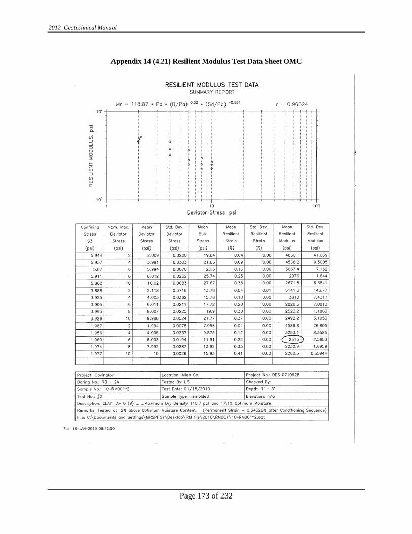
2012 Geotechnical Manual
Page 173 of 232
Appendix 14 (4.21) Resilient Modulus Test Data Sheet OMC

2012 Geotechnical Manual
Page 174 of 232
Appendix 15 (4.21) Resilient Modulus Test Data Sheet OMC+2

2012 Geotechnical Manual
Page 175 of 232
Appendix 16 (7.1) Subgrade Evaluation (example)
Bor
ing
No.
Sta Offset Line Sample No
Depth (ft.) Soil Type
AA
SHTO
C
lass
. SPT (N)
In-situ Dry
Density (pcf)
Max. Dry
Density (pcf)
In-situ %
Comp action
Nat. Moisture
(%)
Opt iMoisture
(%)
% Moi Diff
RB-06 276+00 20’ Lt “A” SS-1 2.0-3.5 Loam A-6 5 110.9 110.0 100.8 14.5 17.8 -3.3
RB-09 290+00 20’ Rt “A” SS-2 3.5-5.0 Silty Clay Loam A-6 13 111.5 110.0 101.4 17.6 17.8 -0.2
RB-11 303+00 30’ Rt “A” SS-1 1.5-3.0 Silty Clay Loam A-6 7 109.1 110.0 99.2 17.8 17.8 0.0
RB-16 322+50 35’ Lt “A” SS-1 2.0-3.5 Silty Clay Loam A-6 9 108.3 110.0 98.4 16.0 17.8 -1.8
RB-22 343+00 20’ Lt “A” SS-1 2.0-3.0 Loam A-6 9 119.5 110.6
RB-27 385+00 35’ Lt “A” SS-1 2.0-3.0 Silty Clay Loam A-6 10 109.8 110.0 99.8 12.7 17.8 -5.1
RB-36 440+00 15’ Lt “PR-A” SS-2 1.5-3.5 Silty Clay Loam A-6 12 108.2 110.0 98.3 18.7 17.8 0.9

2012 Geotechnical Manual
Page 176 of 232
Appendix 17: Peat Unit Weight (example)
Boring No. Station Offset Line Sample
No. Depth (feet) Soil Type AASHTO
Class. SPT (N)
Natural Moisture
(%)
Max. Dry Density
(pcf)
RB-17B 326+00 98’Rt “A” ST-2 16.0-18.0 Silty Clay w/Little Organic Matter A-7-5 0 82.6 91.8
RB-17B 326+50 98’Rt “A” SWT-9 33.5-35.0 Silty Clay w/Little Organic Matter A-7-5 0 103.6 90.2
RB-17B 326+50 98’Rt “A” ST-3 36.0-38.0 Silty Clay w/Little Organic Matter A-7-5 0 71.5 81.0
RB-18 326+50 54’Lt “A” SS-1 0.5-2.0 Silty Clay w/Traces of Organic Matter A-6 2 55.4 92.3
RB-18 326+50 54’Lt “A” SS-4 8.5-10.0 Silty Clay w/Little Organic Matter A-7-5 0 65.0 93.2
RB-18 326+50 54’Lt “A” SS-9 21.0-22.5 Silty Clay w/Little Organic Matter A-7-5 0 119.1 88.8
RB-18B 328+00 51’Lt “A” SS-2 3.0-4.5 Silty Clay w/Little Organic Matter A-7-5 1 89.1 105.2*
RB-19 332+15 35’Rt “A” SS-1 1.0-2.0 Silty Clay w/Traces of Organic Matter Visual 25 35.4 110.3*
Average of Peat Unit Weight 89.5* RB-18D 326+50 30’Lt “A” SS-4 8.5-10.0 Loam A-7-6 16.3 16.3 120.9*
RB-18E 326+45 54’Lt “A” ST-1 5.0-7.0 Clay w/Little Organic Matter Visual 75.6 75.6 119.8
* Not included in average

2012 Geotechnical Manual
Page 177 of 232
Appendix 18- Services to be Furnished by Consultant (APPENDIX “A”) Services to be furnished by CONSULTANT: The CONSULTANT shall make the necessary roadway geotechnical surveys, landslide investigations, and other special investigations and foundation exploration borings for projects at locations within the State of Indiana as directed by INDOT.
Prior to entering upon private property for performing the work, the CONSULTANT shall follow the “Instruction for Entering Upon Private Property“as established by Legislative Acts of 1963. A copy of these instructions is on file with INDOT and is incorporated by reference.
The work shall be performed in accordance with the requirements set out in the current Geotechnical Manual.
The consultant may be required to do all work per project or only a portion thereof, as determined by the INDOT Geotechnical Section. All services may not be required at all times.
If special services other than the Geotechnical (such as geophysical work, traffic control, etc) are required, the Geotechnical CONSULTANT needs to obtain at least three (3) cost estimates before selecting the lowest bidder to perform the work. These estimates shall be submitted to INDOT Office of Geotechnical Engineering with the invoices for the payment purposes.
The CONSULTANT shall obtain and preserve samples of the subsoil as required, perform the necessary laboratory tests, perform the required geotechnical engineering analyses and prepare and furnish the necessary reports covering the information obtained. If the CONSULTANT is requested to perform the laboratory test on the soil samples and rock cores, these samples shall be delivered to its laboratory no later than at the end of each work week. If the samples are to be tested by INDOT they shall be delivered to the Division of Materials and Tests, 120 S. Shortridge Road, Indianapolis, Indiana, no later than the following Monday of each work week. Each soil sample and rock core shall be clearly marked as to project number, contract number, structure number, road number, station, offset, boring number, sample number, core number, blow count depth, etc. INDOT shall determine who will do the laboratory testing and engineering during the drilling operations.
During the drilling operations, whenever a shale material is encountered, the CONSULTANT shall notify INDOT in order to obtain further instructions for sampling procedures. Sampling procedures may include rock core sampling. Shale samples obtained from all core samples shall be tightly wrapped in cellophane or approved material immediately after removal from the core sampler to prevent moisture loss. The core samples shall be labeled in the following manner: a. Project number b. Contract number c. Road Number

2012 Geotechnical Manual
Page 178 of 232
d. Station, offset & elevation e. Depth f. Date g. Sample marking h. Sampled by i. Length core run and length core recovery j. Other And delivered to the Division of Materials and Tests no later than the following Monday at the end of each week’s work.
Upon completion of the laboratory testing all soil samples and rock cores shall become the property of INDOT and shall be disposed of as directed by INDOT. Borings shall be made to the depth specified through whatever type of material is encountered, including boulders, fill and other types of obstructions. No measurements or payment will be made for borings abandoned or lost before reaching the specified depth except as provided below for “false starts“. No boring shall be abandoned without first obtaining the approval from INDOT. If a boring cannot be completed due to encountering underground utilities or structures, the existence and location of which were not previously known, the boring will be considered a “false start“ for which payment will be made. The depth of the false start will be measured and paid for at the unit price per foot established by this contract for the appropriate type drilling.
Sounding items in this contract when used for determining the depth and limits of questionable weak subsurface soils shall only be used when the questionable weak subsurface soils are buried. Other type borings shall be used in order to more accurately determine their extent, after approval has been given by INDOT. The ground water level shall be measured upon completion of the drilling, at 24 hours after completion of the drilling, and at any later convenient times. After measuring the ground water level at completion of the borings, the boring holes shall be suitably covered, so that there will be no hazard to people, animals, or equipment. After 24 hours or later, when the ground water level has been measured and all other observations, records, and information have been obtained, the holes shall be filled in accordance with INDOT’s current “Aquifer Protection Guidelines”. The CONSULTANT shall perform the following services as directed by INDOT: GEOTECHNICAL FIELD In certain locations, INDOT may require the CONSULTANT to perform geotechnical field drilling operations during the night. Work performed at night shall be paid under the item “Night Time”. Any work that is not performed at night shall be paid under the Standard item. No night time drilling shall be performed without obtaining INDOT Geotechnical Section’s approval.
1. a & b and e MOBILIZATION OF DRILLING, CORING EQUIPMENT AND MILEAGE

2012 Geotechnical Manual
Page 179 of 232
This work shall consist of mobilization of equipment to and from the drilling site and shall be paid for from Indianapolis or to the next drilling site under this contract on the basis of the mileage shown on the current official highway map to the nearest town. This item shall consist of a lump sum fee plus a mileage charge. If more than one site is to be drilled, INDOT may schedule the order in which the sites are to be drilled to minimize the total road mileage.
If a combination of truck mounted and skid/ATV-mounted borings exist on any project
and each type of equipment is actually mobilized, then two mobilization fees shall be paid. If the additional cost of doing the truck borings with the skid rig is less than the additional cost of the second mobilization, then all borings will be paid as skid borings, and only one rig will be mobilized. The most cost-effective method should be used. However, if more than one rig type will be needed, a prior approval from INDOT is required.
If a site or a portion thereof is inaccessible due to flooding at the time of rig arrival or
by the time other drilling that can be done is accomplished, and INDOT does not wish to eliminate or relocate the boring location to an accessible location, remobilization will be paid if it is necessary to do the boring at a later date.
Remobilization shall be paid only with prior approval from INDOT. Mobilization of barge (skid) drilling equipment is excluded from this item as it is part
of the cost of barge set-up expense. It shall be the responsibility of the CONSULTANT to determine the equipment needs of each site and to mobilize equipment needed to perform the necessary work.
CPT rig and coring equipment mobilization shall be lump sum plus mileage charge as described above.
c. FIELD COORDINATION WITH UTILITIES
This work shall consist of coordinating the field work with utilities and getting any required permits other than railroad permits. This item will be paid as one lump sum per project regardless of the size of the project or the time spent on these activities.
d. FIELD COORDINATION WITH PROPERTY OWNERS The property owners will be considered for payment if the boring is located on their property and will be paid for as a lump sum basis on the following categories:
i. 1-10 property owners ii. 11-25 property owners iii. Over 26 property owners
Crop damage will be compensated as per Exhibit “C”.

2012 Geotechnical Manual
Page 180 of 232
HAND AND TRUCK DRILLING When the boring or sounding logs are first submitted to the INDOT Geotechnical Section (usually with the first submittal of the geotechnical report), the original field logs should be included.Copies of the field logs are acceptable if they are legible. The cost of all Geotechnical Engineer services shall be included in the cost of boring, drilling and sampling. Engineering supervision during drilling will not be paid separately.
2. TRUCK MOUNTED BORINGS WITH SPLIT SPOON SAMPLING This work shall consist of using a truck mounted drill rig to advance a hole of sufficient diameter for the purpose of taking 2.0 in. (51 millimeters) outside diameter (O.D.) split spoon samples and making standard penetration tests at 2.5 ft. intervals for the first 10 ft. and at 5 ft. intervals thereafter, including a sample at the bottom of the boring with the possibility of taking 3 in. O.D. Shelby Tube and 2 in. diameter rock cores. This work shall be performed in accordance with AASHTO T 206. Payment will be made from the ground surface to the maximum depth of penetration of the augers or casing. A maximum of two wraps of rope around the cathead shall be used to minimize reduction of the energy due to frictional resistance of the falling hammer. Other precautions shall be exercised to ensure a free fall hammer. Drilling fluid or other authorized practices shall be used in circumstances where sand heaves into the casing or as directed by INDOT. Any unusual sampling procedures or results shall be noted on the boring logs. Driving of the split spoon will be discontinued when blow-counts reach one hundred for a penetration of 12 in. or less.
If a sample is not recovered upon retraction of the sampler, one additional attempt with appropriate trap shall be made in order to retrieve a sample for visual classification. No payment will be made for non-recovered samples, unless an additional attempt at recovery is made and recorded on the boring log. 3. TRUCK MOUNTED BORINGS USING DRILLING FLUID This work shall consist of advancing an uncased hole using a Hawthorne rotary drag bit, Tri Cone Roller bit, etc.,and drilling fluid to keep the hole open to a specified elevation for the specific purpose of obtaining undisturbed samples, or rock core samples. 4. TRUCK MOUNTED CORE DRILLING This work shall consist of using a truck mounted drill rig for rock core drilling. Standard diamond core bits and series “NWG” or “NX” or larger double-tube or triple tube core barrels shall be required for making rock core borings. The minimum size of core shall be 2 in. in diameter, except

2012 Geotechnical Manual
Page 181 of 232
INDOT may permit obtaining a 1.6 in. in diameter core if adequate recovery can be obtained. All solid rock shall be drilled with a diamond or saw tooth core bit.Depth of penetration shall be as directed by INDOT. This work shall be performed in accordance with AASHTO T 225. 5. a. TRUCK MOUNTED BORING THROUGH BEDROCK, BOULDERS, OR CONCRETE PAVEMENT
This work shall consist of advancing a hole using truck mounted equipment through bedrock, boulders, or concrete for subgrade investigation. This may require a Hawthorne Rotary Drag Bit, Tri-Cone Roller bit, or any suitable equipment and method to keep the hole open for the purpose of taking SPT or undisturbed samples.
b. BRIDGE DECK CORING AND RESTORATION
This work shall consist of penetrating a bridge deck with coring equipment or other means for the purpose of extending the augers through the deck. The work shall include restoring the bridge deck by patching with quick set concrete or other equivalent means of restoration. A quantity of one shall be paid for each location of coring.
6. CONE PENETROMETER TESTING (CPT)
Cone Penetrometer Test consists of pushing an instrumented Penetrometer into the ground while continuously recording the sleeve friction (fs), cone resistance (qc), pore pressure, and shearwave velocity. Cone Penetrometer testing shall be performed in accordance with ASTM D 5778-95. CPT shall be performed if requested by INDOT along with SPT boring. Pore water pressure measurement will only be performed when requested. Following items shall be applicable to CPT truck mounted exploration services.
a. CPT: SET-UP
This item shall be paid for each set-up of the CPT truck.
b. CPT: SUBSURFACE PROFILING
This item shall consist of penetration cone resistance profiling and providing computer boring logs and ratio in addition to required geotechnical parameters such as soil types, undrained strength, relative density, angle of shearing resistance, etc. This shall be measured from the surface to the cone top and paid for in linear foot.
c. CPT: PROFILING WITH PORE PRESSURE MEASUREMENT
This work shall consist of adding a pressure transducer to the CPT Penetrometer for
measuring soil pore water pressure response to penetration along with other geotechnical parameters.
i. Piezometer Saturation – This work shall consist of meeting all of the requirements of penetrometers as set out in ASTM D-5778.
2012 Geotechnical Manual
Page 182 of 232
ii. This item shall be similar as described in 6 (b). iii. This work consists of determination of pore water pressure dissipation rate and will be paid for at an hourly rate. iv. This work consists of determination of horizontal hydraulic conductivity and consolidation coefficient. This shall be paid for as each test.
d. CPT: PROFILING WITH SHEAR WAVE VELOCITY MEASUREMENT This work shall consist of determining shear wave velocity in addition to geotechnical parameters and will be measured in linear feet from the surface to the cone top.
e. CPT: SAMPLE This work shall consist of taking soil samples at the required depth which shall be paid for each sample. It shall not be paid if unsuccessful attempt was made.
7. HAND OR TRUCK SOUNDINGS This work shall consist of making continuous auger borings with a truck mounted rig, or with a hand auger, for the purpose of determining the depth to rock, the depth through surficial peat, other exposed unstable materials, man-made waste deposits, etc. This item shall also include borings advanced for the express purpose of making core borings in rock or obtaining undisturbed samples at a certain depth in which a casing or drilling fluid is not used to keep the hole open. Measurement shall be from the ground surface to the depth augered. This item shall also include hand borings made in ponds or lakes for the purpose of determining the depth and thickness of unstable sediments. Measurement shall be made from the top of water to the maximum depth of drilling bit penetration and payment thereof shall be full compensation for the drilling work. It shall be the CONSULTANT’s responsibility to determine the elevation and depth of the water at the time the drilling is performed.
8. HAND AUGER DRILLING This work shall consist of using a hand auger, 1 in. (25 millimeters) retraction piston sampler, or a peat sampler to obtain samples for determination of the geotechnical profile. A hand guide power auger may be used for this item with prior approval from INDOT. This work shall be performed in accordance with AASHTO T 306. SKID DRILLING The following items (9 through 13) are to be used when site conditions are such that a skid-mounted, dozer-mounted, or all terrain vehicle drill rig is required to obtain the boring. Borings shall

2012 Geotechnical Manual
Page 183 of 232
also be considered as one of these items when the CONSULTANT is required to use a dozer to get a truck rig to the boring location. If the CONSULTANT chooses to use a skid-mounted, dozer-mounted, or all terrain vehicle rigs to obtain borings which could have been obtained by a truck rig, they shall be considered as truck borings.
When the boring or sounding logs are first submitted to the INDOT Geotechnical Section (usually with the first submittal of the geotechnical report), the original field logs should be included. Copies of the field logs are acceptable if they are legible. The cost of the Geotechnical Engineer services shall be included in the cost of boring, drilling and sampling. Engineering supervision during drilling will not be paid separately.
9. SKID MOUNTED BORINGS WITH SPLIT SPOON SAMPLING This work shall be the same as described in Item No. 2, except for the drilling equipment required. 10. SKID MOUNTED BORINGS USING DRILLING FLUID This work shall be the same as described in Item No. 3, except for the drilling equipment required. 11. SKID MOUNTED CORE DRILLING This work shall be the same as described in Item No. 4, except for the drilling equipment required. 12. SKID MOUNTED BORING THROUGH BEDROCK OR BOULDERS This work shall be the same as described in Item No. 5a, except for the drilling equipment required. 13. SKID MOUNTED SOUNDING This work shall be the same as described in Item No. 7, except for the drilling equipment required.
BARGE DRILLING
The following items (14 through 20) are to be used when flotation equipment is required to make borings over water. Flotation equipment is described as a barge, raft, boat, or platform of sufficient size to support properly and safely the drilling equipment and has sufficient work area for the storage of the necessary tools and supplies required to make water borings. The barge and drilling equipment shall be of sufficient size to operate on any body of water within, or bordering, the State of Indiana and be able to penetrate to depths as required by INDOT. The equipment shall also be capable of obtaining 3 in. O.D. Shelby Tube samples at depths requested by the CONSULTANT and approved by INDOT. Water borings shall be generally defined as those where water is 12 in. or more in depth

2012 Geotechnical Manual
Page 184 of 232
and it is not feasible to doze or build a ramp to the boring location, all subject to prior INDOT approval. It shall be the Consultant’s responsibility to determine the elevation and depth of the water at the time the drilling is performed.
When the boring or sounding logs are first submitted to the INDOT Geotechnical Section (usually with the first submittal of the geotechnical report), the original field logs should be included. Copies of the field logs are acceptable if they are legible. The cost of all Geotechnical Engineer services shall be included in the cost of boring, drilling and sampling. Engineering supervision during drilling will not be paid separately.
14. FURNISHING OF A BOAT This work shall consist of furnishing a boat for the purpose of making hand borings in streams, ponds, or lakes. The charges for the services will be actual cost and detailed documentation should be provided to support the charges. 15. BARGE SET-UP EXPENSE This item shall consist of mobilization, demobilization, equipment rental and setting up of equipment required for barge boring at a drilling site. Only one barge set-up will be allowed per drilling site, unless two different barges are required (i.e., one type for navigable water and one type non-navigable water) in which case two barge set-ups will be allowed. A drilling site is defined for this item as one or more barge borings located less than 5 miles from any other barge boring. The drilling site shall be considered as being on navigable water or non-navigable water as defined by the jurisdiction of the United States Coast Guard. a. NAVIGABLE WATER i. BARGE SET-UP ii. RENTAL OF SUPPORT EQUIPMENT AND/OR BOAT
This item shall consist of the rental of support equipment required to perform barge borings on navigable water. Support equipment such as the tug boats, cranes, additional special equipment, etc., shall be reimbursed at the actual invoice. The CONSULTANT shall obtain the written approval from INDOT before incurring any Support Equipment expenses.
iii. DRILL RIG DOWN TIME
This item shall include the down time required to move the barge from one boring to the next boring on navigable water. This does not include the initial barge set-up on the first boring or the movement of the barge from the final boring (these moves shall be part of Item 15a.i). This work will be reimbursed on a per hour basis.

2012 Geotechnical Manual
Page 185 of 232
b. BARGE SET-UP NON-NAVIGABLE WATER
Rental of support equipment for drilling borings on non-navigable water and the down time required to move the barge from one boring to the next boring are included in this item and will not be paid for separately.
16. ADDITIONAL DISASSEMBLY AND REASSEMBLY a. NAVIGABLE WATER
This item shall consist of disassembly, moving and reassembly of barge equipment when the borings are not located on a continuous body of water. Navigable waters will be defined by the jurisdiction of the United States Coast Guard.
Each such move required will be considered as one additional disassembly and reassembly and INDOT will pay an additional lump sum for each such move required.
b. NON-NAVIGABLE WATER
This item shall consist of disassembly, moving and reassembly of barge equipment when the water is too shallow within the drilling site to float the barge from one drill location to the next if borings are not located on a continuous body of water. Each such move required will be considered as one additional disassembly and reassembly and INDOT will pay and additional lump sum for each such move required.
17. BARGE MOUNTED BORING WITH SPLIT SPOON This work shall be the same as described in Item No. 2, except for the drilling equipment required. 18. BARGE MOUNTED CORE DRILLING This work shall be the same as described in Item No. 4, except for the drilling equipment required. 19. BARGE MOUNTED BORING THROUGH BEDROCK AND BOULDERS This work shall be the same as described in Item No. 5a, except for the drilling equipment required. 20. BARGE MOUNTED SOUNDINGS This work shall consist of working a machine powered continuous flight auger boring from a barge, for the purpose of determining the depth to bedrock, the depth and thickness of surficial peat and other exposed unstable materials or man-made waste deposits, etc. Measurement shall be made from the top of the underlying ground to the depth penetrated. Hand auger or probe soundings may be made from a barge but payment will be made as set out in Item No. 7.

2012 Geotechnical Manual
Page 186 of 232
21. CASING THROUGH WATER This item shall consist of furnishing and installing casing for water holes. The casing may be either a hollow stem auger or a driven casing for borings into the underlying material through water. Measurement for this item shall be from the water surface to the top of the underlying ground surface.
22. UNCASED SOUNDING THROUGH WATER This item shall consist of that portion of barge soundings from the top of water to the top of underlying ground. Measurements of this item shall be from top of water to top of underlying ground. 23. SET-UP FOR BORINGS AND MACHINE SOUNDINGS
a. BORINGS AND MACHINE SOUNDINGS LESS THAN 20 FT. DEEP: This work shall consist of rig set-up for any borings or machine soundings less than 20 ft. deep.
b. ROCK CORING: This work shall consist of setting up equipment for rock core borings.
24. ADDITIONAL 2 IN. SPLIT SPOON SAMPLES This item shall consist of obtaining additional 2 in. O.D. split spoon samples as specified in Item No. 3 by the Standard Penetration Test Procedure in accordance with AASHTO T 206. Payment shall be for split spoon samples obtained in addition to those required in Item Nos. 2, 9, and 17, unless otherwise approved by INDOT. 25. 3 IN. SPLIT SPOON SAMPLES The requirements listed in Item 3 shall apply except the split spoon shall have a 3 in. O.D.
26. 3 IN. SHELBY TUBE SAMPLES This work shall consist of obtaining undisturbed samples by pressing a 3 in. O.D. thin walled tube into soil with a steady push. An attempt shall be made to push the tube 24 in. Payment will be made only when recovery is 50% or greater, with a minimum of 12 in., unless otherwise approved by INDOT. This work shall be performed in accordance with AASHTO T 207.
27. BAG SAMPLES This work shall consist of obtaining disturbed samples of soils by any conventional equipment for moisture density relations, CBR testing, or Resilient Modulus. The total wet weight of sample shall not be less than a). 300 lbs. or b). 25 lbs. The sample shall be placed in appropriate bags and suitably labeled with identifying information.

2012 Geotechnical Manual
Page 187 of 232
If the top of the layer to be sampled lies within 5 ft. of the ground surface, a quantity of one will be paid. An additional quantity of one will be paid for each additional 5 ft. penetrated to reach the top of the layer of the material to be sampled.
28. FIELD VANE SHEAR TEST This work shall consist of performing field vane shear tests in accordance with AASHTO T 223. A quantity of one will be paid for each test performed. 29. 4 ½ IN. CASED HOLE This work shall consist of advancing a cased hole through soil, shale or rock to a specified elevation for installing field instrumentation, etc. Either hollow stem augers or driven casing may be used. Measurement shall be from the top of the ground to the depth of casing penetration. Larger diameter casing will be permitted at no additional cost to INDOT. 30. INSTALLATION OF GEOTECHNICAL INSTRUMENTS
a. INCLINOMETER CASING INSTALLATION
This work shall consist of providing all the tools, equipment and engineering services for installing inclinometer casing at locations and depths specified by the State in accordance with the Aquifer Protection Guidelines, and/or Contract Supplemental Specifications. A plastic flush-jointed casing of 2.75 in OD, or equivalent may be used. This item shall be paid for at the unit price per lineal foot of casing installed. The appropriate type of drilling used for the borehole, as specified by the State, will be paid for as a separate item. Backfilling around the casing shall be tremied neat cement grout and paid for by the item for Special Borehole Backfilling (Item No. 34) in accordance with the Aquifer Protection Guidelines. If the installation is in an area of proposed fill under construction, then the length of pipe added shall be not more than 5 feet at a time as the fill height progresses. Lifts of fill around the casing shall be “B”-Borrow or sand. A Metal Protective Outer Cover for Inclinometer Casing shall be installed as described in Item Number 30, Section d. b. PIEZOMETER INSTALLATION UP TO 25 FT. BELOW THE SURFACE.
This work shall consist of providing all tools and equipment and engineering services for installing piezometers at locations and depths specified by the State in accordance with the Aquifer Protection Guidelines and/or Contract Supplemental Specifications. These piezometers may be of the Pneumatic Type, or of the Hydraulic Cassagrande Type. The Hydraulic type must have provisions for attaching a Bourdon Gauge in case the pore pressure increases enough to raise the water level to above the top of the standpipe. If the piezometer installation is to be of the Cassagrande Type and in an area of proposed fill under construction, then sections of standpipe not longer than five feet shall be added as the fill height progresses, so that the piezometric water level can be measured at any time. Backfill around the standpipes in lifts of embankment shall be of “B”-Borrow material or sand. Each installation shall be marked with the words, “Monitoring Well, do not fill“. The installation shall be supplied with a Metal Protective Outer Covers for Piezometer Casing and shall be installed as

2012 Geotechnical Manual
Page 188 of 232
described in Item 30, Section d. The appropriate type of drilling used for the borehole, as specified by the State, will be paid for as a separate item.
c. PIEZOMETER INSTALLATION DEEPER THAN 25 FT., BELOW THE SURFACE. This item is same as Item b above except for depth involved and the pay item amount. The appropriate type of drilling used for the borehole, as specified by the State, will be paid for as a separate item.
d. METAL PROTECTIVE OUTER COVER FOR INCLINOMETER AND PIEZOMETER CASINGS.
This work shall consist of providing and installing a metal protective outer covers for inclinometer and piezometer installations. These shall be a minimum of 4 in. diameter pipe, or square metal casing, approximately 3 ft. long, and shall be anchored in a concrete pad 3 ft. in diameter and 1 ft. thick, and shall have less than 2 ft. exposed above the ground surface and shall be supplied with a padlockable metal cap. The top of the inclinometer casing or the piezometer tubes shall be between 2 in. to 4 in. below the inside of the cap of the metal protective outer cover. In instances where installation must be flush with the surface, such as in roadways or sidewalks, then standard Water-Meter-Type handhole boxes may be used, instead of the casing described above for the metal protective outer cover. This item shall be paid for at the unit price per each and shall include a metal lid and padlock. One key to the padlock shall be supplied to the INDOT Geotechnical Section at completion of the installation. The keys shall be numbered with the Boring Number of the Boring Log associated with the installation. Each installation shall be permanently marked with the words “Monitoring well, do not fill“.
31. GEOTECHNICAL ENGINEER This work shall consist of furnishing a qualified approved Geotechnical Engineer for work (field checks and meetings, administrative cost, etc.) that is not covered in other items (engineering analysis, report preparations, field coordination, checking shop drawings, reviewing final check prints, foundation review, coordinating work for renting equipment etc.). It shall be paid for at the applicable hourly rate for the time actually spent at the job site/meeting plus travel time. Overnight expenses and the cost of mobilizing to the job site are included in this item, and are not paid for separately. The time accepted for payment shall be rounded to the nearest half hour and a time log should be submitted with the itemization to list the activities and time spent on the project. If the quantity of this pay item is expected to exceed ten hours then prior approval should be obtained from INDOT. This pay item should be used during field checks, during construction, etc. It should not be used during drilling operations, marking the borings, because these costs are included in the cost of drilling operations. 32. RAILROAD EXPENSE Actual cost invoiced by the railroad for railroad permits, flagmen, right of entry, etc., actual cost. The CONSULTANT shall obtain the written approval from INDOT before incurring any Railroad expense.

2012 Geotechnical Manual
Page 189 of 232
33. TWENTY-FOUR HOUR WATER LEVELS This work shall consist of obtaining 24 hour water levels for any boring where it is considered essential for proper design. These shall include structure boreholes not under ponded water (Bridge, Retaining Wall, etc.) for cut sections where seepage and/or slope stability may be a problem, for embankment areas where slope stability analysis may be required, etc.
In cases where the borehole caves in, a slotted PVC pipe shall be installed before the casing is pulled. A 24 hour water level is critical in cut and at grade areas if cohesive soils are encountered in borings. In these cases, soundings shall be located outside of the shoulder in the median or behind the curb. The slotted PVC pipe shall be installed before augers are to be pulled. The hole shall be backfilled as per INDOT Aquifer Protection Guidelines after recording the 24 hour water elevation. A quantity of one shall be paid per borehole, except that the slotted pvc pipe will be paid per foot (meter).
34. SPECIAL BOREHOLE BACKFILLING The work in items a and b shall be accomplished in strict compliance with INDOT’s current “Aquifer Protection Guidelines” dated October 9, 1996, except where the borehole caves in. In this case the borehole shall be backfilled from the top of the cave-in to the ground surface using the “Aquifer Protection Guidelines”.
a. Boreholes from 0.0 ft. to 30 ft. deep; backfilled in accordance with section II.C. Of the Guidelines. Includes all equipment, material and labor to complete the task.
i. SPT ii. CPT
b. Boreholes greater than 30 ft., backfilled in accordance with Section II.C. Of the Guidelines. Includes all equipment, material and labor to complete the task.
i. SPT ii. CPT
c. This work shall include restoring pavement after coring or drilling. Concrete pavement shall be patched with quickset concrete. Asphaltic pavement shall be patched with an asphalt mix. A quantity of one shall be paid at each location.
35. DOZER RENTAL This item shall entail the procurement of a qualified subcontractor to provide and operate a bulldozer for clearing site, and when applicable, constructing pathways and benches for drill rig set-ups. The charge for this service will be actual cost. An invoice copy for the dozer contractor’s

2012 Geotechnical Manual
Page 190 of 232
services will be required to verify the charges. This item shall be used only with INDOT’s prior approval. 36. TRAFFIC CONTROL This work shall consist of providing traffic control services according to the INDOT “Work Zone Safety Manual”, when traffic flow must be restricted in order to conduct drilling or coring operations. The charge for this service shall be a daily rate computed to the nearest one half day. All warning signs, traffic cones, or buffer trucks, etc., required to meet applicable safety standards, shall be provided by the CONSULTANT and paid by INDOT at actual cost. a. FLAG CREW
As required per guidelines in “Work Zone Safety” manual, paid per crew, daily rate computed to nearest ½ day.
b. EQUIPMENT RENTAL
As required per guidelines in “Work Zone Safety” Manual, paid at actual Cost. c. Flag Crew with Equipments This includes the flag crew and the equipments owned by the company. This item can be used on two lane roadway only. The traffic control set up shall be in accordance with INDOT’s Work Zone Safety manual.
37. CENTERLINE SURVEYING This work shall consist of locating the centerline of the road to accurately locate structure and roadway borings, with the use of instrumentation and a qualified survey crew (2 people) when requested by the CONSULTANT and approved by INDOT. The charge for these services will be actual cost.
GEOTECHNICAL LABORATORY 38. SIEVE ANALYSIS This work shall consist of determining the gradation of a sample in accordance with AASHTO T 88. Sieves used shall be U.S. Sieve sized 3.0 in., 2.0 in., 1.50 in., 1.0 in., 0.75 in., 0.5 in., and U.S. Sieve Nos. 4, 8, 10, 40, 200 , and 270, decanted over #270. A grain-size distribution curve shall be provided for this item. 39. HYDROMETER ANALYSIS This work shall consist of performing the Hydrometer Analysis in accordance with AASHTO T 88. The test also includes a specific gravity determination. Silt shall be defined as those soil

2012 Geotechnical Manual
Page 191 of 232
particles from 0.074 to 0.002 mm in size. A grain size distribution curve shall be provided for Items 38 and 39 combined when both are performed. 40. MOISTURE CONTENT TEST This work shall consist of the determination of moisture content in accordance with AASHTO T 265. 41. LIQUID LIMIT This work shall consist of the determination of the Liquid Limit in accordance with AASHTO T 89, Mechanical Method only. Three points shall be determined and no payment will be made for Non-Plastic (N.P.) soil. 42. PLASTIC LIMIT AND PLASTICITY INDEX This work shall consist of the determination of the Plastic Limit and Plasticity Index in accordance with AASHTO T 90. 43. a. UNCONFINED COMPRESSION TEST
This work shall consist of performing the Unconfined Compression Test in accordance with AASHTO T 208. This test shall include initial and final moisture contents, and unit weight determination.
b. REMOLDING OF SOIL SAMPLES WITH CHEMICAL ADMIXTURES IN
CHEMICAL SOIL MODIFICATION/STABILIZATION
This work shall consist of remolding of three blended specimens. Remolding of three samples shall be paid as one unit. If additional samples are necessary, INDOT must approve the quantity prior to the preparation of samples. Any additional samples will be paid at one third of this rate. These remolded samples could also be prepared for other test requirements.
44. SPECIFIC GRAVITY TEST This work shall consist of the determination of the Specific Gravity in accordance with AASHTO T 100. No payment will be made when performed in conjunction with item No. 39, 48, and 49. 45. UNIT WEIGHT DETERMINATION This work shall consist of the determination of the Unit Weight by measurement of the length and diameter as performed in accordance with the appropriate part of AASHTO T 233. No payments will be made when performed in conjunction with Item Nos. 43, 47, and 48.
46. HYDRAULIC CONDUCTIVITY

2012 Geotechnical Manual
Page 192 of 232
This test is conducted to determine the rate of flow of water through the soil mass. Hydraulic conductivity and is determined to evaluate the drainage property of subgrade, base, and Subbase materials. It is determined as the following:
a. CONSTANT HEAD. a. Constant head test, as described in detail in AASHTO T-215 (ASTM 2434), is
generally used to determine the hydraulic conductivity of granular materials. The sample for testing is selected and compacted into the mold. (The compactive efforts affect the hydraulic conductivity.) It is then saturated under vacuum to assure that there is no air in the sample.
b. FALLING HEAD. b. Falling head test shall be performed in accordance with ASTM D5084. The sample
should be compacted and saturated as above for the constant head test. 47. CONSOLIDATION TEST This work shall consist of performing the consolidation test in accordance with AASHTO T 216, except the initial load shall be 125 psf. This test also includes Specific Gravity, initial and final moisture contents, initial and final Degree of Saturation and Unit Weight (density). Time curves for all load increments and e-log-p curve shall also be furnished. 48. TRIAXIAL TEST This work shall consist of performing the Triaxial Test in accordance with AASHTO T 296 or 297. Each test shall consist of three points for plotting a Mohr Failure Envelope and determining the strength parameters. This test shall include initial and final moisture contents, initial and final degree of saturation and initial and final unit weights (densities). The test shall include a specific gravity determination. The specific type of Triaxial Test performed shall be as directed by INDOT. The test shall be either the (a) Unconsolidated-Undrained (UU) test, (b) Consolidated untrained (CU) test, (c) Consolidated-Drained (CD) test, or (d) Pore Pressure Measurement with the UU or CU test and use of back pressure for saturation. 49. SOIL SUPPORT TESTING
a. CALIFORNIA BEARING RATIO (CBR)
This work shall consist of the determination of the California Bearing Ratio (soaked) in accordance with AASHTO T 193 with the following exceptions:
i. Six specimens shall be molded at optimum moisture content, two at approximately 90 percent, two at 95 percent, and two at 100 percent of the maximum dry density, respectively. ii. If the as-molded moisture content of any specimen is more than 0.8 percentage points above or below optimum, the specimen shall be remolded using fresh,

2012 Geotechnical Manual
Page 193 of 232
uncompacted soil. iii. A minimum surcharge weight of 25 lbs shall be used while soaking the test specimens. The surcharge should be calculated based on the pavement cross-section. However, 25 to 30 lbs have been found acceptable. A Dry Density (Abscissa) versus CBR (ordinate) curve shall be plotted and furnished for each sample tested.
b. SUBGRADE RESILIENT MODULUS (MR) This work shall consist of determination of the resilient modulus value in accordance with AASHTO T 307. This test shall be performed in accordance to laboratory procedure manual. This test shall be performed based on the following.
i. Testing shall either on Shelby tube or remolded samples. ii. Shelby tube samples shall be saturated to 95% prior to MR testing. Two (2) remolded specimens may each be substituted for Shelby Tubes. If remolded specimens are to be used, they shall be prepared to 95% of Maximum dry density, one specimen at optimum moisture content and the second specimen at 2 points above OMC. Test performed at each remolded sample shall be considered as one test for payment purpose. iii. Data sheet of MR test showing the stress sequence shall be provided. Data sheet includes: confining stress, deviator stress, resilient strain, permanent strain, resilient modulus, height and diameter of specimen, specimen preparation method, water content before and after the test, and initial dry density and wet density. iv. Plot of deviator stress vs. resilient modulus with respect to each confining stress shall be submitted. v. Based on the resilient modulus test, 3 regression equations to predict resilient modulus shall be provided.
1)32
1 )()( k
a
dka pPa
pkMrσθ
=
2)
21
kkMr θ= 3)
21
kdkMr σ=
Where, k1, k2, k3, = regression coefficients, θ = sum of principal stresses; pa = reference pressure = 100 kpa ≈ 2000 psf ≈14.5 psi; and σσ= deviator stress in the same unit as pa. A reasonable resilient modulus for the proposed subgrade shall be recommended.

2012 Geotechnical Manual
Page 194 of 232
50. STANDARD MOISTURE DENSITY RELATIONSHIP TEST This work shall consist of performing Standard Moisture Density Relationship in accordance with Method A, or Method C whichever is applicable as part of AASHTO T99. A minimum of four points on this curve with at least two points on each side of optimum shall be performed. When Standard Moisture - Density is performed in conjunction with CBR the samples shall be prepared and tested in accordance with AASHTO T 193, except the sample shall be mixed and then cured for 48 hours prior to molding the specimens. 51. LOSS-ON-IGNITION TEST This work shall consist of the determination of the Loss-on-Ignition (Organic Content) in accordance with AASHTO T 267. 52. PH TEST This work shall consist of performing the pH Test in accordance with AASHTO-T-200 using only distilled water. The test should be performed on all classification test samples and others as necessary. When the test is performed on moderate to non-organic material, samples size should be 0.7 oz. of material passing the No. 4 sieve (4.75 mm). The samples shall be prepared in accordance with AASHTO T 87. The pH test for stabilization/modification shall be performed in accordance with the Eades and Grim procedures. 53. COLLAPSE POTENTIAL EVALUATION TEST This test shall be performed on silt content soils such as “Loess” in accordance with ASTM D5333. FUTURE SHALE INVESTIGATION INDOT may request borings and certain tests of shale for purposed of classification soundness, and recommendations for placement in highway construction. If INDOT requests such work, it will specify the test procedures to be used. Payment for such work will be determined in accordance with Section B of Appendix “D” in this contract.
GEOTECHNICAL ENGINEERING The work described in Engineering (Items 54 through 62) shall include review and correlation of various test results related to embankment stability, material placement, and other geotechnical engineering considerations. Engineering analysis shall be performed after the CONSULTANT has determined an analysis is necessary and has received INDOT’s approval to perform the analysis. All telephone conversations collecting information from, and coordinating with, other consultants, INDOT employees and other parties involved in the project shall be included under these engineering items. 54. GEOTECHNICAL PROFILE AND RELATED WORK

2012 Geotechnical Manual
Page 195 of 232
This item is specifically for use in connection with roadway geotechnical profile and special geotechnical problem projects and shall be performed in accordance with the current requirements set out in Exhibit “C”, the Geotechnical Manual. If a pavement soil subgrade investigation is made, drawings will be prepared to properly present this information. Ten copies of the Geotechnical Profile and Soil Subgrade Investigation drawings shall be furnished to INDOT. A lump sum payment will be made for up to one mile of roadway. Additional lengths of roadway will be rounded off to the nearest mile and payment will be made per mile. Round up for 0.50 mile or more and round down for less than 0.50 miles. Secondary lines will be included in this quantity only when there is at least one boring on the “S” line and when the “S” line is for an interchange or an intersection with the main line. Numerous additional lines in rest areas and parking lots, additional lines adjacent to and parallel to the mainline, and multiple lines for EB & WB or NB & SB divided highways will not be counted as additional mileage except where the two sides of the divided highway diverge on separate alignments. 55. GEOTECHNICAL REPORT This work includes a discussion of Project Identification and background, Scope and Procedure, Topography, Geology, Drainage, Field and Laboratory Investigation Procedures, Proposed pavement cross section, General and Specific Analyses and Recommendations, as well as any other items needed to make a complete Geotechnical Report. Appendices to the report shall include summaries of the results of all laboratory tests performed, all boring and sounding logs, pavement core data if subgrade investigation is performed, sketches and computation for all final Structure, Settlement and Stability Analyses, etc. After the report is accepted, and the design has been completed, the CONSULTANT will review the Final Check Prints and foundation review to see that the design is in accordance with the geotechnical recommendations. The cost of this review shall be included in the cost of the report. If a pavement soil subgrade investigation is required, it shall be performed as per the requirements of INDOT - Geotechnical Section as outlined in “Procedures of Performance of Soil Subgrade Investigation under Existing Pavement” and the results shall be included in the Geotechnical Report. This work includes a discussion of field and laboratory investigation procedures, proposed pavement, cross-section, and some possible causes of subgrade problems under the existing pavements, General and Specific Analyses and Recommendations, Soil Subgrade Investigation Drawings, etc. Appendices to the report shall include summaries of results of all laboratory and field tests performed, all boring and sounding logs, pavement core data sketches and computations, etc.
One copies of the Geotechnical Report shall be furnished to INDOT. INDOT is in the process of switching to electronic transfer of reports. The format for the reports and drawings/logs should be a Windows based version and compatible with INDOT’s existing programs. A lump sum payment will be made for up to one mile of roadway. Additional lengths of roadway will be

2012 Geotechnical Manual
Page 196 of 232
rounded off to the nearest mile and payment will be made per mile. Round up for 0.50 mile or more and round down for less than 0.50 mile. Secondary lines will be included in this quantity only when there is at least one boring on the “S” line and when the “S” line is for an interchange or an intersection with the main line. Numerous additional lines in rest areas and parking lots, additional lines adjacent to and parallel to the mainline, and multiple lines for EB & WB or NB & SB divided highways will not be counted as additional mileage except where the two sides of the divided highway diverge on separate alignments. When a Geotechnical Report is not required, the CONSULTANT shall furnish INDOT with one copy of the Roadway and/or Structure Borings and this cost shall be included in the drilling process. 56. SETTLEMENT ANALYSIS AND RECOMMENDATIONS FOR EMBANKMENT This work shall consist of performing settlement analysis at a specified embankment cross-section based on consolidation test results. The CONSULTANT shall furnish computations for total estimated settlement (cross section of up to 3 points if requested), a plot of percent total estimated settlement vs. time (at the centerline) assuming the most likely drainage conditions, etc. A quantity of one will be paid for each section analyzed and quantity of one-third (1/3) will be paid for each additional point, for each of the following types of analysis:
a. PROPOSED EMBANKMENT b. PROPOSED AND EXISTING EMBANKMENT 57. GROUND MODIFICATION DESIGN
This work shall consist of a complete analysis and recommendations for a ground improvement technique such as Wick Drains, Pressure Grouting, Stone Columns, etc. The CONSULTANT shall furnish all the information needed for a complete design. 58. SLOPE STABILITY ANALYSIS This work shall consist of making Slope Stability Analyses (Sliding Block or Rotational) at specified sections to analyzed proposed or existing conditions. One analysis will be authorized for payment for each section for each model analyzed. For nonsymmetrical cross-sections where more than one part of the cross-section is analyzed, a quantity of one will be authorized for payment for each separate analysis performed. Additional analysis will be authorized for each corrective measure to be analyzed. A Stage Construction alternate will be considered as one additional analysis regardless of the number of stages analyzed. All corrective measures shall be defined as to the limits of the correction. Factor of Safety computations shall be made until a minimum factor of safety has been established. All models will be approved by INDOT prior to performing the analysis. 59. BRIDGE FOUNDATION ANALYSIS AND RECOMMENDATIONS

2012 Geotechnical Manual
Page 197 of 232
This work shall consist of Bridge Foundation Analysis and Recommendations as per current INDOT’s LRFD foundation design policy. All models will be approved by INDOT prior to performance of the analyses. a. SHALLOW FOUNDATION
This item shall include all analyses and computations required to make complete recommendations for a satisfactory shallow foundation to support the proposed loading conditions at each pier location, except for settlement analysis. Shallow foundations are defined as spread footings, reinforced concrete mats, etc. Each pier analyzed shall be considered as one analysis.
b. DEEP FOUNDATION
i. This item shall include all analyses and computations required to make complete recommendations for a satisfactory deep foundation to support the proposed loading conditions (including axial and lateral loads) at each pier location, except for settlement analysis. Deep foundations are defined as piles, drilled shafts, etc. Wave Equation analysis shall be paid separately. Each pier analyzed shall be considered as one analysis.
ii. This item shall include a design stage Wave equation analyses using latest
“GRLWEAP” and computations required to make complete recommendations for pile drivability. One analysis shall be performed per structure. Any additional analyses shall be approved by the Engineer in writing.
iii. This item shall include all analyses and computations required to make a
complete recommendation for liquefaction potential performed for each bridge structure, where necessary.
iv. This item shall include a final design stage Pile Group analyses using the latest
GROUP 3D software or FB-Pier. Approval from INDOT shall be obtained before performing these analyses. One analysis shall be paid per each pier or bent analyzed. Any additional analyses shall be approved by the Engineer in writing. This item shall include a design stage.
c. SETTLEMENT ANALYSIS FOR BRIDGE PIER FOUNDATIONS
This work shall consist of performing Settlement Analysis (cross section if requested by INDOT) at a specified bridge pier foundation based on consolidation test results. The CONSULTANT shall furnish computations for total estimated settlement, a plot of percent total estimated Settlement vs. Time assuming the most likely drainage conditions, etc. A quantity of one will be paid for each bridge pier foundation analyzed, for each of the following conditions:

2012 Geotechnical Manual
Page 198 of 232
i. BRIDGE PIER
ii. EMBANKMENT-PLUS-PIER
iii. EMBANKMENT-PLUS PIER-PLUS ALL OTHER LOADS
d. FOUNDATION ON BEDROCK
This work shall consist of making bridge recommendations when the foundation should be placed on bedrock, whether the foundations are deep or shallow. This item will be used only when no analysis is required for any support of the bridge structure. A quantity of one will be paid for each bridge.
60. RETAINING STRUCTURE ANALYSIS AND RECOMMENDATIONS This work shall consist of Retaining Structure Analysis and Recommendations. Included are conventional retaining walls, bridge abutments, piles or drilled-in piers, or any other retaining type structures. The analyses and recommendations shall include all computations necessary to assure the stability of the retaining structure, except for settlement analysis. Each section of a retaining structure analyzed shall be considered as one analysis. All models will be approved by INDOT prior to performance of the analysis. a. CONVENTIONAL RETAINING STRUCTURE
Conventional retaining structures including cantilever concrete retaining walls, bridge abutments, and other retaining-type structures such as MSE Walls or bin walls, except for pile or drilled-in-pier types.
i. SHALLOW FOUNDATION
This item shall include all analyses and computations required to make complete recommendations for a satisfactory shallow foundation to support the proposed loading conditions at each section, except for settlement analysis. Shallow foundations are defined as spread footings, reinforced concrete mats, etc.
ii. DEEP FOUNDATION
This item shall include all analyses and computations required to make complete recommendations for a satisfactory deep foundation to support the proposed loading conditions at each section, except for settlement analysis. Deep foundation is defined as piles, drilled-in piers, etc.

2012 Geotechnical Manual
Page 199 of 232
iii. SETTLEMENT ANALYSIS FOR RETAINING WALL FOUNDATIONS
This work shall consist of performing Settlement Analysis (cross section if requested) at a specified section based on consolidation test results. The CONSULTANT shall furnish computations for total estimated settlement, a plot of percent total estimated Settlement vs. Time assuming the most likely drainage conditions etc. A quantity of one will be paid for each section analyzed.
b. PILE RETAINING STRUCTURE ANALYSIS AND RECOMMENDATIONS
i. FREE STANDING STRUCTURE
This item shall include the analyses and computations required to determine the lateral loads which will be imposed on the structure elements, the depth of embankment required for stability of typical section, etc. The final recommendations shall include the station limits of the structural elements, their offsets, penetration depths, the soil and/or rock stresses for which the elements of the retaining structure should be designed, etc. Any other design parameters which are pertinent to the recommendations for such a retaining structure should also be included as part of this item.
ii. RETAINING STRUCTURE WITH TIE-BACK SYSTEM
This work shall be the same as described above under Item 60 (b-1) except for the additional recommendations pertaining to a tie-back system. The recommendations for the tie-backs shall include the capacity of the tie-backs, the penetration required for stability, the spacing of the tie-backs, any other design perimeters pertinent to the tie-back system recommendations, etc.
c. DRILLED-IN-PIER RETAINING STRUCTURE ANALYSIS AND
RECOMMENDATIONS
i. FREE-STANDING STRUCTURE
This item shall include the analyses and computations required to determine the lateral loads which will be imposed on the structural elements, the depth of embedment required for stability of a typical section, etc. The final recommendations shall include the station limits of the structural elements, their offsets, penetration depths, the soil and/or rock stresses for which the elements of the retaining structure should be design, etc. Any other design parameters which are pertinent to the recommendations for such a retaining structure should also be included as part of this item.
ii. RETAINING STRUCTURE WITH TIE-BACK SYSTEM
This work shall be the same as described above under Item 60 (c-1) except for the additional recommendations pertaining to a tie-back system. The recommendations for the tie-backs shall include the capacity of the tie-backs, the penetrations required

2012 Geotechnical Manual
Page 200 of 232
for stability, the spacing of the tie-backs, any other design parameters pertinent to the tie-back system recommendations, etc.
d. SOIL NAILING WALL
This work shall consist of analyses and recommendations for a soil nailing wall. The analyses shall consider all the forces and moments acting on the wall and the nailing system. The final recommendations shall include the size, capacity and spacing of the nails, the penetration parameters pertaining to the soil nailing system. A quantity of one shall be paid for each typical section analyzed.
61. SEEPAGE ANALYSIS This work shall consist of performing seepage analysis including recommendations at specific sections to estimate the quantity of seepage through and/or underneath the embankment, etc. Stability against piping and any other related analyses shall be analyzed as a part of the seepage analysis. However, prior approval must be obtained before performing the analysis.
The CONSULTANT shall furnish computations for estimated seepage, calculated factor of safety against piping and all necessary curves and sketches. Additional analysis will be authorized for corrective measures at specific sections. Quantity of seepage factor of safety against piping etc. shall be made until tolerable limits of seepage and an adequate factor of safety are achieved while analyzing a corrective measure. Each section analyzed shall be considered as one analysis for payment purposes. 62. DEEP DYNAMIC COMPACTION ANALYSIS This work shall consist of Deep Dynamic Compaction Analysis including recommendations, etc. This shall include all necessary analyses and computations required to make complete recommendations for a satisfactory foundation to support the proposed loading of the embankment and/or to minimize the future settlement to a tolerable limit. Prior approval must be obtained before performing the analysis. The CONSULTANT shall furnish computations for densification of foundation soils or material and all necessary curves and sketches, etc. The CONSULTANT shall prepare the curves to show the relationship between the weight, height and number of drops, etc. and the densification of the soil or material to facilitate the operation during construction. Each site analyzed shall be considered as one analysis for payment purposes.
CONSTRUCTION INSPECTION AND MONITORING
Under this section, the consultant will provide services in the field during construction to inspect and monitor geotechnical related construction activities. This work shall consist of:

2012 Geotechnical Manual
Page 201 of 232
a. Furnishing qualified inspectors in the field during construction of specialized geotechnical structures such as drilled piers and tie-back walls.
b. Monitoring geotechnical instruments such as piezometers inclinometers and settlement
plates. c. Integrity testing such as crosshole sonic logging, impulse response spectrum test, video
logging, pressuremeters and pile dynamic load tests.
The consultant will be reimbursed for this work in accordance with the following items:
63. FIELD INSPECTOR This work shall consist of furnishing an approved inspector for field work. The inspector will have a minimum of five years of experience in the same field, inspecting or supervising construction of structures similar to the structures under contract. Prior approval will be required for each inspector before construction.
The inspector’s duties should include sampling, testing, inspecting and assisting the INDOT Project Supervisor in approving the Contractor’s work.
This work shall be paid for at the applicable hourly rate for the time actually spent at the project site. Overnight expenses and the cost of mobilizing to the project site are included in this item, and are not paid for separately. The time accepted for payment shall be rounded to the nearest half hour. For payment, the consultant will prepare an itemization of pay quantities, get it approved by the INDOT Project Supervisor, and submit it to the INDOT Materials and Tests Division. If redesign is required during construction, the analyses will be paid for at one half the rates listed in the Engineering Section if the same consultant performed the original geotechnical report. Otherwise, the analyses will be paid at the rates listed in Section III. 64. MONITORING GEOTECHNICAL INSTRUMENTS This work shall consist of recording data from instruments installed for monitoring the subsurface conditions and the performance of geotechnical structures. This work shall be paid in accordance with Item #64 above, except that the travel time will also be paid. Monitoring that takes place during construction, while the field inspector is on the project site, will not be paid separately.

2012 Geotechnical Manual
Page 202 of 232
65. INTEGRITY TESTING This work shall consist of performance of special tests to insure the integrity of drilled shaft foundations during construction. These tests may include crosshole sonic logging (CSL), impulse response spectrum test (IRS Test),video logging, pressuremeter testing, etc. The consultant shall be reimbursed at the actual invoice Actual cost, including furnishing the testing instruments, the after-test analysis, and preparation of the report. The 10% will cover all miscellaneous costs such as coordination, consultation, and interpretation of the data if necessary. 66. DYNAMIC PILE ANALYSIS This work shall consist of performing a wave equation analysis using a computer program (GRLWEAP 87 or others as approved by INDOT) and writing recommendations. This shall include all analyses and computations required to make complete recommendations for an adequate pile driving system at each bridge structure for the proposed loading conditions. All necessary curves shall be prepared for each pile driving system with a specific pile to show the conditions during driving operations. “Blows per foot” vs. “Ultimate resistance” and “Blows per foot” vs. “Driving Stress” shall be plotted. Based on the maximum allowable compressive stress, blow count per foot at ultimate resistance and minimum driving time required to achieve ultimate resistance, an adequate pile driving system shall be recommended. Also, any other information or recommendations required by INDOT shall be provided. INDOT will provide for the CONSULTANT the information on the proposed pile driving system adequate to fill out the upper portion of Form 2 (Driving System, Pile and Soil Data). The CONSULTANT will determine soil parameters based on the Geotechnical Investigation. Each pile driving system analyzed at a bridge shall be considered as one analysis, with prior approval from INDOT.
When this work is complete as a part of Item 68 (Dynamic Pile Load Test),it will not be paid for separately. 67. STATIC LOAD TEST This work shall be done by a professional geotechnical engineer and shall consist of performing the static load test on designated foundations (piles, drilled shafts, etc.) According to INDOT Standard Specs., Section 701 (revised 1996), the work shall include furnishing the gauges and related accessories, attaching the gauges to the test pile, directing and monitoring the performance of the test up to the prescribed loads as per standard specs. And preparing and submitting the report on the load test. A quantity of one shall be paid for each foundation tested for furnishing the gauges, test analysis and preparation of test report etc. The presence of the test engineer in the field for the test shall be paid in hours as per item (31).

2012 Geotechnical Manual
Page 203 of 232
68. DYNAMIC PILE LOAD TEST This work shall be done by a professional geotechnical engineer and shall consist of a dynamic pile load test done with PDA (Pile Driving Analyzer) according to INDOT Standard Specs., Section 701. The work shall include furnishing the PDA instrument and necessary accessories such as transducers and wires, attaching the transducers to the test pile and connecting them to the PDA, operating the PDA during pile driving up to the required load and recording the data on magnetic tape or computer disk. After the initial driving is over, a restrike will be done after a minimum of 24 hours or up to 72 hours and a dynamic load test will be required. This work shall include doing the CAPWAP analysis in accordance with the requirements in this appendix and the WEAP analysis as per Item 66 herein. The work shall also include submitting the report on the dynamic test as per Standard Specs., Section 701 and a computer diskette containing the results of PDA, CAPWAP, and WEAP, all within 72 hours after restrike. The report shall conform to ASTM D 4945 and shall include the evaluation of hammer and pile driving system performance, pile driving stresses, pile structural integrity and load bearing capacity of the pile. A quantity of one shall be paid for each pile tested including furnishing the instrument, the after-test analyses and preparation of report etc. The presence of the test engineer in the field for the test shall be paid in hours as per Item 31 herein. 69. CAPWAP-C ANALYSIS REQUIREMENTS Each test pile receiving a Dynamic Pile Load Test shall also receive a Case Pile Wave Analysis Program, or CAPWAP-C, analysis. This analysis shall be performed on a single blow from the original pile driving and shall be compared to the analysis done on one of the first 2 blows of the restrike test. The cost of this analysis shall be included in the cost of dynamic measurements and analysis.
Each CAPWAP-C analysis shall include the information as follows:
i. Graph showing the bearing capacity versus blow count and pile stress versus blow count. ii. Simulated static load test curves for the tip and the top of the pile, if applicable. iii. Re-Evaluation of the soil parameters used in the original wave equation analysis by means of matching the measured and computed values of forces, velocities, and displacements. iv. Static resistance distribution along the length of the pile.
70. FINAL CONSTRUCTION INSPECTION REPORT This work shall consist of preparing a report summarizing the scope of the work, the results of construction inspection and monitoring, recommendations made for proposed changes during
2012 Geotechnical Manual
Page 204 of 232
construction, and copies of geotechnical test reports (load tests and integrity tests) for he entire project. A quantity of one will be paid for each report. This payment will also cover administrative costs.
FOUNDATION EVALUATION BY NON-DESTRUCTIVE METHODS
71. FOUNDATIONS
The problem of unknown foundation is of major concern for the Department of Transportation. Bridge inventory does not have design, as-built plans available to document the type, depth, geometry, or material incorporated in the foundation of bridges or other highway structures. This evaluation is also needed for scour pier. Without foundation type and depth information, it is impossible to evaluate accurately the scour potential of these structures. This work consists of foundation depth, type, geometry, materials, integrity and stiffness around the foundation and preparation of a final report. NDE may include ultra seismic vertical profiling, parallel seismic, GPR, and parallel seismic with cone penetrometer performed by a qualified and approved engineer. These evaluations may be performed by the surface borehole method and/or the surface testing method. Both methods shall be paid per pier or foundation and only as a actual cost. This work shall be reported in electronic format (Windows version) with drawings and sketches. An appropriate or combination of methods may be used for successful evaluation. Other proven methods may be considered if approved by the Chief Geotechnical Engineer. If requested, the proven method shall require a case history of similar work, location, personnel qualifications and experience. Other items associated with this work, such as drilling, sampling, etc., shall be paid for in accordance as described in the Geotechnical Field, and Laboratory Sections.
GEOTECHNICAL PROJECT MANAGEMENT This work consists of managing the complete Geotechnical Investigation on a project and shall be performed by a Lead Geotechnical CONSULTANT. The Geotechnical Project Management will be the responsibility of the Lead Geotechnical CONSULTANT where the work is carried out by more than one Geotechnical CONSULTANT. The Lead Geotechnical CONSULTANT shall be responsible for providing a complete set of recommendations for the design and construction of the project. The management includes project coordination, general oversight, updating information on the project website (ProjectWise /SharePoint/similar site), scheduling, prioritizing, monitoring scheduled performances, providing general and technical support, and review of all geotechnical analyses and recommendations prepared by other team members (Geotechnical CONSULTANTS). All the work shall be performed in accordance with the latest INDOT guidelines and procedures. 72. Project Management:
a. Project Coordination: This work shall consist of coordinating with INDOT, Design Team Consultants, other Geotechnical Consultants within the team, and Specialty Consultants, (i.e., Surveyors, Geophysical work specialists, etc) in order to complete the project in accordance with the Department’s guidelines and procedures in an efficient and timely manner. A quantity of one will be paid for each mile of roadway work involved. The measurement of length of the roadway will be in accordance with Item No. 55 of the Appendix A of this contract.

2012 Geotechnical Manual
Page 205 of 232
b. Project Website: This work shall consist of updating the information on a shared ProjectWise/SharePoint/internet web-site, posting minutes of meetings, technical memorandum, schedule of geotechnical investigations, geotechnical investigation data, revisions, other project related information, geotechnical plans and profiles, etc. as appropriate. A lump sum payment will be made for this work.
73. Geotechnical Review:
a. Structure Report: This work shall consist of Preliminary review by the lead Geotechnical Consultant of the work performed by the other team members (Geotechnical Consultants) before submitting to the INDOT Office of Geotechnical Engineering for their review and approval. A quantity of one will be paid for each structure report, regardless of the size of the structure. All twin bridge structures shall be considered as one unit. Other structures such as retaining structures, drainage structures shall not be considered for payment under this item. b. Roadway Report: This work shall consist of Preliminary review by the lead Geotechnical Consultant of the work performed by the other team members (Geotechnical Consultants) before submitting to the INDOT Office of Geotechnical Engineering for their review and approval. A quantity of one will be paid for each mile of roadway. The measurement of length of the roadway will be in accordance with Item No. 55 of the Appendix A of this contract. The review of retaining structure, drainage structures will be included in the roadway report review and no additional payments will be made.
PAVEMENT INVESTIGATION
1. MOBILIZATION OF CORING EQUIPMENT This work shall consist of mobilization of coring equipment to and from the project site. This item will be used when pavement cores are obtained independently of geotechnical sampling. 2. MOBILIZATION MILEAGE FOR CORING EQUIPMENT This work shall consist of the travel mileage of the coring equipment. The authorized mileage will be the distance from the State Capitol Building to the middle of the project site. This item will be used when pavement cores are obtained independently of geotechnical sampling. 3. PAVEMENT CORE (PARTIAL DEPTH) This work shall consist of obtaining pavement cores to the depth of bituminous concrete overlay on cement concrete pavements. 4. PAVEMENT CORE (FULL DEPTH) This work shall consist of obtaining pavement cores the full depth of pavement such as a cement concrete pavement, a cement concrete pavement with the bituminous concrete overlay, or a full depth bituminous concrete pavement.
2012 Geotechnical Manual
Page 206 of 232
5. SUBBASE SAMPLE This work shall consist of coring and/or sampling of the sub base. This work is to be accomplished when requested in conjunction with full depth pavement cores.
6. CEMENT CONCRETE PAVEMENT CORE DENSITY DETERMINATION: When required, the hardened concrete unit weight of the Portland cement concrete portion of the core shall be determined in accordance with ASTM C 642. Prior to the determination of the density, the specimen shall be submerged in lime-saturated water for at least 24 hours. The density shall be determined by bulk specific gravity after immersion, except boiling of the specimen will not be required. The report shall include the core number; the weight of the surface-dry sample in air after immersion, the weight of the sample in water after immersion, the unit weight of the sample in pcf to the nearest 1.0 pcf, and the presence of reinforcing steel shall be noted, if present in the tested sample. 7. CEMENT CONCRETE CORE COMPRESSIVE STRENGTH TEST: When required, the compressive strength of the Portland cement concrete portion of the core shall be determined in accordance with ASTM C-42, and if a 2:1 height/diameter ratio is not achieved, the compressive strength shall be adjusted. Prior to testing, the specimen shall be submerged in lime-saturated water for at least 40 hours. The report shall include the core number, the core diameter, the capped core height, the adjustment factor (when required), the maximum load in pounds(kilograms), the compressive strength calculated to the nearest 10 psi (69 kilopascal), and any defects in either the specimens or caps. 8. BITUMINOUS EXTRACTION TEST: This work shall consist of performing a quantitative extraction of bitumen from asphalt paving mixtures in accordance with Indiana Test Method No. Ind. 571-89. 9. SIEVE ANALYSIS OF EXTRACTED AGGREGATE TEST: This work shall consist of the following: After the bitumen content has been determined, as specified in Item 8, a sieve analysis of the extracted aggregate shall be made using the following procedure:
a. Nest the sieves in sequence, No. 200 (0.0029 in.) on the pan, then the #100 (0.0059 in.) #50 (0.0118 in.), #30 (0.0236 in.), #16 (0.046 in.), #8 (0.093 in.), and #4 (0.187 in.). Place the coarse aggregate sieves, in sequence from the smallest to the largest used, on top of the fine aggregate sieves. The largest sieve used will be the one controlling the maximum size of the coarse aggregate being used in the mixture.
b. Carefully pour the sample on the top sieve, attach the cover and fasten the assembly to the mechanical shaker.

2012 Geotechnical Manual
Page 207 of 232
c. Shake the sample for ten minutes. In no case shall fragments in the sample be turned or manipulated through the sieves by hand.
d. Starting with the largest sieve used, weigh and record the aggregate weight retained on each individual sieve, including that in the pan. If you have more than 7.0 ounces retained on an 8 in. (200) round sieve then the sieves are overloaded. The sample should then be split and rerun.
e. Using results obtained in (d) above, calculate and record the percentage passing each sieve to the nearest one tenth percent (0.1%).
10. RECOVERY OF ASPHALT FROM SOLUTION BY ABSON METHOD: This work shall be accomplished in accordance with AASHTO T 170 for the Abson Method, AASHTO T-49 for the Asphalt Penetration Test and AASHTO T201 and 202 for the Asphalt Viscosity Test. 11. THEORETICAL MAXIMUM SPECIFIC GRAVITY TEST: This work shall be accomplished in accordance with AASHTO T- 209.
12. BULK SPECIFIC GRAVITY TEST:
This work shall be accomplished in accordance with AASHTO T- 166. 13. AIR VOIDS CALCULATIONS: This work shall be accomplished in accordance with AASHTO T- 269. 14. CORE REPORT FOR PARTIAL DEPTH CORE 15. CORE REPORT FOR FULL DEPTH CORE: The work for items 14 and 15 shall be in accordance with the following:
a. CONCRETE PAVEMENT CORE
The recovered core shall be reassembled and a sketch of the core drawn to scale showing the thicknesses of the various materials, such as asphaltic concrete, Portland cement concrete, location and size of the reinforcing steel, etc. The sketch shall be oriented to show maximum detail and shall include locations of cracks, fractures, voids, etc. with explanatory notes, if deemed necessary for completeness. The total core depth shall be measured from the recovered core in accordance with INDOT Standard Specification, Section 501.23(c). The core hole shall be adequately patched using Portland Cement Concrete Mix Design in accordance with INDOT Standard Specifications, Section 305.06(a) or an equal INDOT approved procedure. Each core shall be numbered, the stationing and offset shall be determined for each number core, and these shall be recorded on Core Report TD-441 (attached). The core sketches shall be attached to the report. The general type of coarse aggregate shall be noted on the sketch (i.e., stone, gravel, air-cooled bast-furnace slag, etc.).

2012 Geotechnical Manual
Page 208 of 232
The CONSULTANT shall retain all core samples for a period of one year after coring in an easily identifiable state and shall notify INDOT prior to disposal of the core samples.
b. ASPHALT PAVEMENT CORE
Core Report TD-441 (attached) is to be completed and attached. Also to be attached to this report is a tabulation of the thickness of the layers with a description of these layers. All core holes shall be patched in an approved manner. Storage and disposal of cores shall be handled in accordance with paragraph a.
16. PAVEMENT ANALYSIS AND REPORT The CONSULTANT shall make a general evaluation of the existing pavement conditions, the cores obtained and the results of all laboratory tests performed and evaluate their impact on the proposed design. This analysis will be performed only with prior approval from INDOT. Upon completion and final approval of the work by INDOT, the CONSULTANT shall deliver to INDOT the following, which shall become the property of INDOT:
a. Ten copies of the Soils Report and the Soils Profile for the Roadway Soil Survey on
each project. The format for the reports and drawings/logs should be a Windows based version and compatible with INDOT’s existing programs.
b. Ten copies of the Structure Boring Report at each site including the following: The format for the reports and drawings/logs should be a Windows based version and compatible with INDOT’s existing programs.
c. A plan showing the location of all holes referenced to the survey centerline. i. A true cross section of each boring showing thickness, soils classification, and position and penetration resistance of each soil stratum found between the surface and the bottom of the hole. ii. Free water elevations at completion and 24 hours after completion of the drilling.
d. Reports covering special tests and analysis listed in Section A2 of Appendix “D” are to
be furnished in quantities as designated by INDOT at the time the work is authorized.

2012 Geotechnical Manual
Page 209 of 232
Appendix 19 Compensation for Consultants
APPENDIX "D”COMPENSATION I. Amount of Payment
A. The CONSULTANT shall receive as payment for the work performed under this contract the total fee not to exceed $ , unless a supplement is executed by the parties which increases the maximum amount payable.
The CONSULTANT shall receive payment for the work performed under this contract related to geotechnical services based on the specific cost per unit multiplied by the actual units of work performed. Payment to the CONSULTANT on the basis of the unit prices shall be full compensation for technical supervision of the work by the CONSULTANT, WHEN REQUIRED BY INDOT, mobilization and demobilization of equipment where approved by INDOT, supplying all equipment, tools, labor, materials, supplies, utilities and incidentals necessary for the prosecution of the work, staking boring locations, running level circuits to establish ground elevation at each hole, and for furnishing rights of entry, permits, licenses and insurance required by INDOT.
GEOTECHNICAL FIELD
Unit Unit Price 1. Mobilization and Field Coordination a. SPT Rig Each $ b. CPT Each $ c. Field Coordination with Utilities Lump Sum $ d. Field Coordination With Property Owners i. 1 – 10 Lump Sum $ ii. 11 – 25 Lump Sum $ iii. Over 25 Lump Sum $ e. Mileage Per Mile $
HAND AND TRUCK DRILLING
2. Truck Mounted Borings With Split-Spoon Sampling
a) Standard Foot $ b) Night Time Foot $

2012 Geotechnical Manual
Page 210 of 232
Unit Unit Price
3. Truck Mounted Borings Using
Drilling Fluid a) Standard Foot $ b) Night Time Foot $
4. Truck Mounted Core Drilling
a) Standard Foot $ b) Night Time Foot $
5. Truck Mounted Borings
a. Truck Mounted Boring Through Bedrock Or Boulders or Concrete Pavement
i) Standard Foot $ ii) Night Time Foot $
b. Bridge Deck Coring and Restoration
i) Standard Each $ ii) Night Time Each $
6. Cone Penetrometer Testing a. Set up
i) Standard Each $ ii) Night Time Each $ b. Subsurface Profiling
i) Standard Foot $ ii) Night Time Foot $
c. Profiling with Pore Pressure Measurement i. Piezometric Saturation a. Standard Each $
b. Night Time Each $ ii. Penetration
a. Standard Foot $ b. Night Time Foot $
iii. Pore Water Dissipation Test
a. Standard Per Hour $ b. Night Time Per Hour $
iv. Hydraulic Conductivity And
Consolidation

2012 Geotechnical Manual
Page 211 of 232
Unit Unit Price
a. Standard Each $ b. Night Time Each $
d. Profiling With Shearwave Velocity Measurement
i. Standard Foot $ ii. Night Time Foot $
e. Sample a. Standard Each $ b. Night Time Each $ 7. Hand or Truck Soundings
a) Standard Foot $ b) Night Time Foot $
8. Hand Auger Drilling
a)Standard Foot $ b)Night Time Foot $
SKID DRILLING
9. Skid Mounted Borings With
Split-Spoon Sampling a) Standard Foot $ b) Night Time Foot $
10. Skid Mounted Borings Using Drilling Fluid
a) Standard Foot $ b) Night Time Foot $
11. Skid Mounted Core Drilling
a) Standard Foot $ b) Night Time Foot $
12. Skid Mounted Boring Through Bedrock or Boulders
a) Standard Foot $ b) Night Time Foot $

2012 Geotechnical Manual
Page 212 of 232
Unit Unit Price
13. Skid Mounted Soundings
a) Standard Foot $ b) Night Time Foot $
BARGE DRILLING
14. Furnishing of a Boat Actual Cost $ 15. Barge Set-Up Expenses a). Navigable Water i. Barge Set-up Each $ ii. Rental of Support Actual Cost $ Equipment and/or Boat iii. Drill Rig Down Time Hour $ b). Barge Set-up Non-Navigable Water Each $ 16. Additional Disassembly and Reassembly a). Navigable Water Each $ b). Non-Navigable Water Each $ 17. Barge Mounted Borings With Split-Spoon Foot $ 18. Barge Mounted Core Drilling Foot $ 19. Barge Mounted Boring Through Bedrock and Boulders Foot $ 20. Barge Mounted Soundings Foot $ 21. Casing through Water Foot $ 22. Uncased Sounding through Water Foot $ 23. Set Up For Boring, Coring and Machine Sounding.
a). Borings and Machine Soundings
Less Than 20 ft. Deep Each $ b). Rock Coring. Each $
24. Additional 2 in. Split-Spoon Sampling Each $ 25. 3 in. Split-Spoon Samples Each $

2012 Geotechnical Manual
Page 213 of 232
Unit Unit Price 26. 3 in. Shelby Tube Samples Each $ 27. Bag Samples
a). 300 lbs. Sample Each $ b). 25 lbs. Sample Each $
28. Field Vane Shear Test
a). Standard Each $ b). Night Time Each $
29. 4 ½ in. Cased Hole Foot $ 30. Installation of Geotechnical Instruments
a). Inclinometer Casing Installation ia). Standard Foot $ iia).Night Time Foot $ b). Piezometer Installation
Up To 25 ft. below the Surface Each $ c). Piezometer Installation
Deeper Than 25 ft. below the Surface Each $ d). Metal Protective Outer Cover For
Inclinometer and Piezometer Casings Each $ 31. Geotechnical Engineer per Hour $ 32. Railroad Expense Actual Cost $ 33. Twenty Four Hour Water Levels a). Field Measurements
i). Standard Each $ ii). Night Time Each $ b). PVC Slotted Pipe Foot $
34. Special Borehole Backfilling a). Up to 30 feet i). SPT
1) Standard Each $ 2) Night Time Each $
ii). CPT
1) Standard Each $ 2) Night Time Each $

2012 Geotechnical Manual
Page 214 of 232
Unit Unit Price
b). More Than 30 feet
i). SPT 1) Standard Per Foot $ 2) Night Time Per Foot $
ii). CPT
1) Standard Per Foot $ 2) Night Time Per Foot $
c). Pavement Restoration
1) Standard Each $ 2) Night Time Each $
35. Dozer Rental Actual Cost $ 36. Traffic Control a). Flag Crew per Day $ b). Equipment Rental Actual Cost $ c). Flag Crew with Equipments per Day $ 37. Centerline Surveying Actual Cost $
GEOTECHNICAL LABORATORY 38. Sieve Analysis Each $ 39. Hydrometer Analysis Each $ 40. Moisture Content Test Each $ 41. Liquid Limit Each $ 42. Plastic Limit & Plasticity Index Each $ 43. a). Unconfined Compression Test Each $
b). Remolding Of Soil Samples With Chemical
Admixtures in Chemical Soil Modification/Stabilization (3 Samples is Equal to 1 Unit) Each $
44. Specific Gravity Test Each $ 45. Unit Weight Determination Each $

2012 Geotechnical Manual
Page 215 of 232
Unit Unit Price 46. Hydraulic Conductivity Test a. Constant Head Each $ b. Falling Head Each $ 47. Consolidation Test Each $ 48. Triaxial Test a. Unconsolidated-Undrained (UU) Each $ b. Consolidated-Undrained (CU) Each $ c. Consolidated-Drained (CD) Each $ d. Pore Pressure Measurement with a. or b. and Use of Back Pressure for Saturation Each $ 49. Soil Support Testing a. California Bearing Ratio Test Each $ b. Subgrade Resilient Modulus Each $ 50. Standard Moisture-Density Relationship Test Each $ 51. Loss on Ignition Test Each $ 52. PH Test Each $ 53. Collapse Potential Evaluation Test Each $
GEOTECHNICAL ENGINEERING
54. Geotechnical Profile and Related Work a. Without Soil Subgrade Drawings First Mile Lump Sum $ Each additional mile Per Mile $ b. With Soil Subgrade Drawings
First Mile Lump Sum $ Each additional mile Per Mile $ c. Soil Subgrade Drawings (only)
First Mile Lump Sum $ Each additional mile Per Mile $ 55. Geotechnical Report a. Without Soil Subgrade Investigation First Mile Lump Sum $ Each additional mile Per Mile $

2012 Geotechnical Manual
Page 216 of 232
Unit Unit Price b. With Soil Subgrade Investigation First Mile Lump Sum $ Each additional mile Per Mile $ c. Soil Subgrade Investigation (only) First Mile Lump Sum $ Each additional mile Per Mile $ 56. Settlement Analysis and Recommendations for Embankment a. Proposed Embankment Each $ b. Proposed and Existing Embankment Each $ 57. Ground Modification Design Each $ 58. Slope Stability Analysis a. C,∅, or C and ∅ Analysis Each $ b. Corrective Measures Each $ c. Stage Construction Corrective Each $ Method 59. Bridge Foundation Analysis and Recommendations a. Shallow Foundation Each $ b. Deep Foundation:
i. Deep Foundation Analyses Each $ ii. Wave Equation Analyses Each $
iii. Liquefaction analysis Each $ iv. Group -3D analysis Each $ c. Settlement Analysis for Bridge Pier Foundation i. Bridge Pier Each $ ii. Embankment Plus Pier Each $ iii. Embankment Plus Pier Plus All Other Loads Each $ d. Foundation on bedrock Each $ 60. Retaining Structure Analysis Recommendations a. Conventional Retaining Structures i. Shallow Foundation Each $ ii. Deep Foundation Each $ iii. Settlement Analysis For Retaining Wall Foundation Each $ b. Pile Retaining Structure Analysis and Recommendations i. Free Standing Structure Each $ ii. Retaining Structure with Tie-Back System Each $

2012 Geotechnical Manual
Page 217 of 232
Unit Unit Price c. Drilled-in-Pier Retaining Structure Analysis and Recommendations i. Free Standing Structure Each $ ii. Retaining Structure With Tie-Back System Each $ d. Soil Nailing Wall Each $ 61. Seepage Analysis Each $ 62. Deep Dynamic Compaction Analysis Each $
CONSTRUCTION INSPECTION AND MONITORING 63. Field Inspector Per Hour $ 64. Monitoring Geotechnical Instrumentation Per Hour $ 65. Integrity Testing Actual Cost $ 66. Dynamic Pile Analysis Each $ 67. Static Load Test Each $ 68. Dynamic Pile Load Test Actual Cost S 69. CAPWAP-C Analysis Each $ 70. Final Construction Inspection Report Each $
FOUNDATION EVALUATION BY NON-DESTRUCTIVE METHODS 71. a. Surface Test/Pier or Foundation Actual Cost $
b. Borehole Test/Pier or Foundation Actual Cost $
GEOTECHNICAL PROJECT MANAGEMENT
72. Project Management a. Project Coordination per Mile $ b. Project Website Lump Sum $ 73. Geotechnical Review a. Structure Report each $ b. Roadway Report per Mile $

2012 Geotechnical Manual
Page 218 of 232
Unit Unit Price
PAVEMENT INVESTIGATION
1. Mobilization of Coring Equipment Each $ 2. Mobilization Mileage for Coring Equipment per Mile $ 3. Pavement Core (Partial Depth) Each $ 4. Pavement Core (Full Depth)
1) Standard Each $ 2) Night Time Each $
5. Subbase Sample Each $ 6. Cement Concrete Pavement Core Density Determination Each $ 7. Cement Concrete Core Compressive Strength Test Each $ 8. Bituminous Extraction Test Each $ 9. Sieve Analysis of Extracted Aggregate Test Each $ 10. Recovery of Asphalt from Solution by Abson Method Each $ 11. Theoretical Maximum Specific Gravity Test Each $ 12. Bulk Specific Gravity Tests Each $ 13. Air Voids Calculations Each $ 14. Core Report for Partial Depth Core Each $ 15. Core Report for Full Depth Core Each $ 16. Pavement Analysis and Report Each $ II. METHOD OF PAYMENT
a. The CONSULTANT shall submit invoice vouchers to INDOT for partial payment on the account for the work completed no sooner than the time of submittal of the initial geotechnical report for any particular project. The invoice vouchers shall be submitted to:

2012 Geotechnical Manual
Page 219 of 232
Indiana Dept of Transportation Office of Geotechnical Services
Attn: Athar Khan 120 South Shortridge Road Indianapolis, Indiana 46219
The invoice vouchers shall represent the value, to INDOT, of the partially completed work as of the date of the invoice voucher. The CONSULTANT shall attach thereto a summary of each pay item to this Appendix, showing the actual units of work performed for the pay item. If INDOT does not agree with the amount claimed by the CONSULTANT on an invoice voucher, it will send the CONSULTANT a letter by regular mail and list the differences between actual and claimed progress. The letter will be sent to the CONSULTANT's address on page 1 of this contract or the CONSULTANT's last known address.
b. Except as provided at Sections II.C and II.D. of this Appendix, INDOT for and in
consideration of the rendering of the engineering services INDOT, for and in consideration of the rendering of the engineering services provided for in Appendix “A”, agrees to pay to the CONSULTANT for rendering such services the unit prices established above in the following manner:
1. For each pay item, and upon receipt of invoices from the CONSULTANT and
the approval thereof by INDOT, payments covering the work performed shall be due and payable to the CONSULTANT, such payments to be equal to the multiplication of the unit price for the item by the number of units of work performed for the item.
The CONSULTANT will be paid for the work described in Item 31 of “Appendix A” in accordance with the following negotiated hourly billing rates per classification:
Classification Hourly Rate
Geotechnical Engineer $
For the actual hours of work performed as specified in Item 31 of Appendix “A” by essential personnel exclusively on this contract.
c. For those services performed by other than the CONSULTANT, the CONSULTANT will
be reimbursed for the actual invoice for the services performed by other than the CONSULTANT, provided that each such invoice shall be subject to approval as reasonable by INDOT prior to any reimbursement therefore.

2012 Geotechnical Manual
Page 220 of 232
d. The actual amount payable shall be determined in accordance with a final audit by INDOT’s Division of Accounting and Control.
[Remainder of Page Intentionally Left Blank]

2012 Geotechnical Manual
Page 221 of 232
Appendix 20 Listing of FHWA Publications
FHWA FHWA-IP-77-8 The Texas Quick-Load Method for Foundation Load Testing-Users Manual
FHWA-TS-78-209 Guidelines for Cone Penetration Test-Performance and Design
FHWA-IP-84-11 Handbook on Design of Piles and Drilled Shafts Under Lateral Load
FHWA-RD-86-185 Spread Footings for Highway Bridges
FHWA-RD-86-186 Prefabricated Vertical drains VOl.I, Engineering Guidelines
FHWA-HI-88-009 Soils and Foundations Workshop Manual – Second Edition
FHWA-IP-89-008 The Pressuremeter Test for Highway Applications
FHWA-SA-91-042 Static Testing of Deep Foundations
FHWA-SA-91-043 Manual on the Cone Penetrometer Test
FHWA-SA-91-044 Manual on the Dilatometer Test
FHWA-SA-91-048 Com624P-Laterally Loaded Pile Analysis Program for the
Microcomputer Version 2.0
FHWA-SA-92-045 EMBANK-A Microcomputer Program to Determine One-
Dimensional Compression Due to Embankment Loads
FHWA-SA-93-068 Soil Nailing Field Inspectors Manual
FHWA-SA-94-005 Advance Course on Soil Slope Stability: Volume I, Slope Stability
Manual
FHWA-SA-94-034 CBEAR – Bearing Capacity Analysis of Shallow Foundations Users
Manual.
FHWA-SA-94-035 The Osterberg CELL for Load Testing drilled Shafts and Driven
Piles
FHWA HI-95-038 Geosynthetic Design and Construction Guidelines
FHWA-RD-95-172 Load Transfer for Drilled Shafts in Intermediate Geomaterials
FHWA-RD-96-016 thru 019 Drilled and Grouted Micropiles: State of Practice Review
Vol I-Vol IV
FHWA-SA-96-039 RSS Reinforced Slope Stability A Microcomputer Program User’s
Manual
FHWA-SA-96-069R Manual for Design & Construction Monitoring of Soil Nail Walls
FHWA-RD-96-179 thru 181 Determination of Pile Driveability and Capacity from
Penetration Test, Vol I-Vol III
FHWA-HI-97-021 Subsurface Investigation

2012 Geotechnical Manual
Page 222 of 232
FHWA-RD-97-130 Design Manual for Permanent Ground Anchor Walls
FHWA-HI-98-034 Geotechnical Instrumentation
FHWA-RD-98-065thru 068 Summary Report of Research on Permanent Ground Anchor
Walls
FHWA-RD-99-170 Extrapolation of Pile Capacity from Non-Failed Load Test
FHWA-IF-04-021 Application of Geophysical Methods to Highway Related Problems
FHWA-NHI-05-042and 043 Design and Construction of Driven Pile Foundations, Reference
Manual Volumes I & II
FHWA-NHI-05-094 Load and Resistance Factor Design for Highway Bridge Substructures
And Earth Retaining Structures

2012 Geotechnical Manual
Page 223 of 232
Appendix 21 – Listing of AASHTO Tests
AASHTO Subject AASHTO Standard Classification of Soils and Soil-Aggregate Mixtures for M 145
Highway Construction Purposes
Standard Test Method for Specific Gravity and Absorption of Course T 85
Aggregate
Standard Test Method for Particle-Size Analysis of Soils T 88
Standard Test Method for Liquid Limit, Plastic Limit, and T 89
Plasticity Index of Soils
Test Method for Shrinkage Factors of Soils by the Mercury Method T 92
Test Method for Laboratory Compaction Characteristics of Soil Using T 99
Standard Effort (12,400 ft-lbf/ft³ (600 kN-m/m³)) Standard Test Method for Specific Gravity of Soils T 100
Test Method for Laboratory Compaction Characteristics of Soil Using T 180
Modified Effort (56,000 ft-lbf/ft³ (2,700 kN-m/m³))
Density of Soil in-Place by the Sand Cone Method. T 191-02
Standard Practice for Soil Investigation and Sampling by Auger Borings T 203
Standard Test Method for Penetration Test and Split-Barrel Sampling of Soils T 206
Standard Practice for Thin-Walled Tube Geotechnical Sapling of Soils T 207
Standard Test Method for Unconfined Compressive Strength of Cohesive Soil T 208
Standard Test Method for Permeability of Granular Soils (Constant Head) T 215
Standard Test Method for One-Dimensional Consolidation Properties of Soils T 216
Standard Test Method for Field Vane Shear Test in Cohesive Soil T 223
Standard Practice for Diamond Core Drilling for Site Investigation T 225
Standard Test Method for Direct Shear Test of Soils Under Consolidated
Drained Conditions T 236
Standard Practice for Using Hollow-Stem Augers for Geotechnical Exploration
and Soil Sampling T 251
Pore Pressure T 252
Standard Test Method for Rock Mass Monitoring Using Inclinometers T 254
Standard Test Method for One-Dimensional Swell or Settlement Potential of
Cohesive Soils T 258

2012 Geotechnical Manual
Page 224 of 232
Subject AASHTO
Standard Test Method for Laboratory Determination of Water (Moisture)
Content of Soil and Rock T 265
Standard Test Methods for Moisture, Ash, and Organic Matter of Peat T 267
and Other Organic Soils
Determining Water-Soluble Sulfate Ion Content in Soil T 290-95
Resilient Modulus-Soils T 294
Standard Test Method for Unconsolidated, Undrained Compressive Strength of
Cohesive Soils in Triaxial Compression T 296
Standard Test Method for Consolidated Undrained Triaxial Compression Test
for Cohesive Soils T 297
Standard Test Method for High-Strain Dynamic Testing of Piles T 298
Determining the Resilient Modulus of Soils & Aggregate Material T 307-99
In Place Density and Moisture Content of Soil and Soil Aggregate by Nuclear
Methods (Shallow Depth) T 310-06

2012 Geotechnical Manual
Page 225 of 232
Appendix 22 – Listing of Indiana Test Methods (ITM)
GEOTECHNICAL SERVICES INDIANA TEST METHODS (ITM)
Policy 03/19/10 R. Walker Indiana Test Method Of Procedure Committee
ITM 208 01/01/2008 M. Zaheer Permeability Of Aggregates
ITM 215 01/01/08 N. Siddiki Recycled Foundry Sand Toxicity Text
ITM 505 01/01/08 M. Zaheer Five-Cycle Slake Resistance Test On Shale
ITM 506 04/18/11 R. Walker Field Determination Of Moisture Content Of Soil
ITM 507 07/09/10 N. Siddiki Calcium Carbonate Content In Soils Using Sequential Loss On Ignition
ITM 508 11/09/10 N. Siddiki Field Determination Of Deflection Using Light
Weight Deflectometer
ITM 902 03/06/09 M. Doherty Verifying Sieves
ITM 906 04/06/10 M. Doherty Verifying Ovens
ITM 507 N. Siddiki Classification of Marly Soils
2012 Geotechnical Manual
Page 226 of 232
Appendix 23 – Aquifer Protection Guidelies
INDIANA DEPARTMENT OF TRANSPORTATION
DIVISION OF MATERIALS AND TESTS
GEOTECHNICAL SECTION
Aquifer Protection Guidelines
The concern for the protection of our ground water natural resources and the prevention of further contamination of that resource prompted the 1987 Indiana General Assembly to pass a ground water protection bill, known as Senate Bill No. 7. This bill amended the existing Indiana Code and created a new chapter identified as IC-25-39 (also referred herein as the "code"). Although, the code specifically exempts wells drilled for the sole purpose of evaluating the foundation characteristics of earth materials to support bridges, roadways, buildings or other engineered structures.", the INDOT is taking steps to substantially follow the intent of the Indiana Code and modify bore hole abandonment procedures for all INDOT supervised drilling.
I. General Guidelines Prior to the commencement of all geotechnical drilling, the current master list of known and/or suspected contaminated areas, compiled by the Indiana Department of Environmental Management (IDEM), shall be consulted to determine if the project falls within one of the designated areas. If the project does not cross one of the designated areas, the work shall commence in accordance with these guidelines.
If the project does involve one of these areas, the INDOT Chief Geotechnical Engineer shall consult with the Indiana Department of Natural Resources - Division of Water (DNR) and the IDEM to receive a written directive on how to proceed. If during drilling on the project a sanitary landfill is encountered, or evidence of surface or subsurface contaminants is noted, the drilling shall be stopped and the INDOT Chief Geotechnical Engineer shall be notified immediately. Drilling shall not commence again without his approval. When Indiana Code IC-25-39 is referred to in the following paragraphs the most current Indiana Administrative Code requirements are to be followed. II. Bore hole Abandonment Procedure without Instrumentation Unless special backfilling guidelines are required, these procedures shall be followed. All depths are determined from natural ground surface. Therefore in fill sections, the fill height will be subtracted from the total depth before applying these guidelines.

2012 Geotechnical Manual
Page 227 of 232
A. Bore Holes 10 feet or less (after cave-in): Salvaged soil from the bore hole shall be used for backfilling these bore holes.
Backfilling shall be accomplished by rodding or tamping the soil in 24" or thinner lifts to prevent settlement of the backfill and leakage of surface water into the bore hole.
B. Bore Holes from 10 to 30 feet deep (after cave-in): The bore hole shall be backfilled in accordance with Section A, using salvaged soil
from the bore hole, from the bottom to a depth seven (7) feet below ground surface. Five (5) feet of bentonite or neat cement shall then be placed in the bore hole in such a manner to form an effective plug against runoff water entering the bore hole. The last two (2) feet of bore hole shall be backfilled with salvaged soil from the bore hole.
C. Bore Hole greater than 30 feet (after cave-in):
Complete slurry backfill is required for these bore holes. The following procedure can
be used as a guideline, but the procedure shall not be interpreted to modify or supersede the Code.
1. Equipment:
a) Backfill pipe of 1 1/2" flush jointed PVC or suitable drill rod. b) Two 150 to 250 gallon stock tanks. c) Two "Masons" hoes or other suitable "mud" mixer. d) Slurry pump, Wilder Trim line type is suggested.
2. Materials:
a) Bentonite - small granular (like "Benseal"), or Portland Cement.
b) Polymer - anionic liquid emulsion used to retard the natural swell of bentonite. c) Fresh Water.
3. Bentonite Slurry Specifications:
If bentonite slurry is used, it shall have a minimum of 1.5 pounds of bentonite per gallon of water. The polymer should be mixed at the manufacturer's suggested rate, usually near 1 quart per hundred gallons of water. The polymer should be mixed with the water before introduction of the bentonite. No more than 100 gallons of water should be prepared at one time.
4. Procedure:
Regardless of the depth of the bore hole, no more than 35 feet of bore hole shall be backfilled in one batch. If necessary the procedure shall be repeated in 35 foot stages until backfilling is complete.

2012 Geotechnical Manual
Page 228 of 232
a) The backfill rods shall be lowered to within 6 inches of the bottom of the hole and held in place with a rod clamp. The slurry is then pumped until it's within 2 feet from the surface or 35 feet of bentonite has been pumped which ever occurs first. If the slurry is within 2 feet of the surface, the rods are removed while pumping the last of the slurry. As soon as the rods are clear of the hole, the pump inlet hose should be shifted to the second stock tank to pump fresh water to clear the pump and rods of slurry. The top 2 feet of the bore hole shall be enlarged to 4 inches larger than the drilled diameter (8" enlarged to 12") and a cap of concrete 3 inches thick poured. The remaining hole can then be backfilled with salvaged soil from the bore hole.
b) If the hole is only partially filled, place the inlet tube into fresh water before withdrawing the backfill tube. Then use water to clear the tube as it is withdrawn. After the tube is withdrawn and cleared, prepare the next batch of slurry. All subsequent stages are pumped after the backfill tube is inserted 6 inches into the previous slurry plug. This insures no voids are present in the backfill and to clear all water from the bore hole. The hole backfilling shall be stopped 2 feet below ground surface and capped with 3" of concrete, then covered with salvage soil.
III. Installation and Abandonment Procedures for Inclinometer Casing and Piezometers. A. Inclinometer 1. Installation:
Inclinometer casing shall be installed in accordance with AASHTO Designation T254 Standard Method for Installing, Monitoring and Processing Data of the Traveling Type Slope Inclinometer, Part I, except as modified herein.
Section Modifications 2.1.1. Minimum bore hole diameter is 8 inches.
2.2.1. Only round extruded aluminum guide casing with four
equispaced longitudinal grooves on the inside of the casing shall be used. Other types of casing may only be used with prior written approval of the INDOT.
2.6.1. A steel pipe with either a threaded cap or lockable hinged lid
shall be used.
3.1. The bore hole shall be 8 inches in diameter and extend a
minimum of 10' into sound rock. 3.3. Hollow stem augers and roller bits are the approved boring
methods.

2012 Geotechnical Manual
Page 229 of 232
4.0. Only aluminum casing shall be used without prior written
approval.
4.2.2. Each joint shall be thoroughly taped to prevent intrusion of the
slurry backfill.
5.0. Only neat cement grout consisting of 94 pounds of Portland
cement mixed with no more than 6 gallons of water will be permitted. No more than 5 %, by weight, of additives to improve fluidity will be allowed.
The grout shall be pumped into the bore hole from the bottom in
a continuous operation to prevent voids in the backfill.
2. Inclinometer Abandonment Procedure:
a) If the inclinometer casing is not crushed or obstructed for its entire length, bentonite or neat cement may be used to backfill the casing to within two feet of the ground surface. At this point, the casing shall be terminated and capped with concrete.
b) If the inclinometer casing is obstructed or crushed, the casing shall be abandoned using bentonite slurry or neat cement only. Care should be taken to ensure the lower portion of the casing is adequately grouted.
B. Piezometer Installation:
1. Installation:
Piezometers shall be installed in accordance with AASHTO Designation T252 Standard Method for Measurements of Pore Pressure in Soils, except as modified herein.
Section Modification 2.1.1. Open observation wells are not permitted. 2.1.2. Standard well points are not permitted. 3.1. Driven installation is not permitted.
3.2.1.1. Similar hammer - cable assemblies are acceptable with prior approval.
3.2.2. 2" I.D. Casing is not acceptable. The following shall be used.

2012 Geotechnical Manual
Page 230 of 232
a) A minimum four (4) inch nominal diameter bore hole in soil should be strictly adhered to, since a smaller diameter hole will create problems in correctly installing the bentonite backfill material.
b) A minimum three and three-quarter (3 3/4) inch diameter bore
hole in bedrock should be strictly adhered to, since a smaller diameter hole will create problems in correctly installing the bentonite backfill material.
c) The maximum number of piezometers that can be installed in
any one bore hole will depend upon the diameter of the bore hole. For the minimum diameter outlined above, only two (2) piezometers can be installed. Correctly installing the bentonite can be difficult when more than two (2) piezometers are placed in the minimum diameters outlined above.
3.2.2.2. The Piezometer stone assembly shall be handled in the following
manner.
The porous piezometer stone should be soaked in water for several hours prior to installation. The saturated piezometer stone shall be attached to the length of 3/8 inch (inside diameter) polyvinylchloride (PVC) standpipe tubing by means of a leak proof joint. The bottom end of the saturated piezometer shall be plugged with a rubber stopper. The piezometer stone and the standpipe tubing shall be filled with clean water and lowered to the bottom of the hole. While lowering, a small excess head shall be maintained in the tube to assure that a small amount of water is flowing out of the stone.
3.2.3.
to Disregard these sections and replace with the following: 3.2.8.
a) The casing shall then be pulled one and one-half (1 1/2) feet
above the elevation of the top of the piezometer stone and water saturated OTTAWA sand placed down the hole (to the elevation of the top of the piezometer stone). The layer of OTTAWA sand should not be tamped. Raise the casing one (1) foot and add one (1) foot of untamped saturated OTTAWA sand. Repeat until the OTTAWA sand is a minimum of six (6) inches below the elevation of the strata break (between the stratum being monitored and the stratum immediately above).
In the case where no strata break occurs, the untamped saturated
OTTAWA sand shall be placed a minimum of one (1) foot above the elevation of the top of the piezometer stone, or as directed.

2012 Geotechnical Manual
Page 231 of 232
b) The casing shall then be pulled an additional two (2) feet and a
minimum one (1) foot bentonite seal is to be placed in six (6) layers two (2) inches thick. The bentonite seal should be a minimum of six (6) inches above the strata break. Use tamping hammer to insure the bentonite is in place, but do not tamp into the sand. A thin layer of fine gravel may be dropped on each layer to prevent the hammer from sticking. This completes the installation of the deepest piezometer.
c) In the event that only one piezometer is to be installed in the
hole, bentonite will be added and compacted to completely fill the remainder of the hole, as the casing is withdrawn and finished in accordance with item 14.
In the event that more than one piezometer is to be installed in
the hole, bentonite will be added to a predetermined depth to permit installation of the upper piezometer at a specified depth. This compacted bentonite will be added between the bentonite seal of the lowest piezometer and will form the lower seal of the next higher piezometer.
d) The casing shall then be pulled two (2) feet and a minimum one
(1) foot bentonite seal placed in six (6) layers two (2) inches thick. Use tamping hammer to insure the bentonite is in place, but do not tamp to drive the bentonite into the sand. A thin layer of fine gravel may be dropped on each layer to prevent the hammer from sticking. The top of this bentonite seal should be one (1) foot below the elevation of the bottom of the next piezometer stone.
e) Completion of the next piezometer stone shall be accomplished
using the procedure outlined above starting at No. 7 and repeated until the uppermost piezometer stone is installed.
f) Upon completion of the uppermost piezometer, the drill casing
shall be pulled out and the remainder of the hole shall be backfilled with compacted bentonite to a depth of about three (3) feet. A protective threaded metal pipe casing about three (3) feet long shall be installed at the top of each hole, backfilled to one (1) foot depth and then cemented. The inside of the casing shall then be filled with three (3) inches of sand (this prevents losing dropped caps). A locking steel cap shall be securely placed onto the protective casing.
g) All piezometer standpipe tubes shall be capped and properly
identified to insure accurate monitoring records.

2012 Geotechnical Manual
Page 232 of 232
2. Piezometer Abandonment.
Piezometers shall be abandoned by pumping a bentonite slurry down the piezometer standpipe until the stone and standpipe are full. The standpipe(s) shall be terminated two (2) feet below ground surface and capped with concrete.
C. Water Monitoring Well.
1. Installation and abandonment procedure shall be in accordance with Indiana
Code 310 IAC 16 and IC25-39.