gmsg circuit breaker instruction manual (3.8 mb)
TRANSCRIPT
Power Transmission & Distribution
5kV - 15kV Vacuum Circuit BreakerType GMSG
InstructionsInstallationOperationMaintenanceE50001-U229-A285-X-US00

Hazardous voltages and high-speed moving parts.
Will cause death, serious injury or property damage.
Always de-energize and ground the equipment beforemaintenance. Maintenance should be performed only byqualified personnel. The use of unauthorized parts in the repairof the equipment or tampering by unqualified personnel willresult in dangerous conditions which will cause death, severeinjury or equipment damage. Follow all safety instructionscontained herein.
IMPORTANT
The information contained herein is general in nature and not intended for specific
application purposes. It does not relieve the user of responsibility to use sound practices in
application, installation, operation, and maintenance of the equipment purchased. Siemens
reserves the right to make changes in the specifications shown herein or to make
improvements at any time without notice or obligations. Should a conflict arise between the
general information contained in this publication and the contents of drawings or
supplementary material or both, the latter shall take precedence.
QUALIFIED PERSON
For the purpose of this manual, a qualified person is one who is familiar with the
installation, construction or operation of the equipment and the hazards involved.
In addition, this person has the following qualifications:
(a) is trained and authorized to de-energize, clear, ground, and tag circuits
and equipment in accordance with established safety procedures.
(b) is trained in the proper care and use of protective equipment such as rubber
gloves, hard hat, safety glasses or face shields, flash clothing, etc., in accordance
with established safety practices.
(c) is trained in rendering first aid.
NOTE
These instructions do not purport to cover all details or variations in equipment, nor toprovide for every possible contingency to be met in connection with installation, operation,or maintenance. Should further information be desired or should particular problems arisewhich are not covered sufficiently for the purchaser's purposes, the matter should bereferred to the local sales office.
The contents of this instruction manual shall not become part of or modify any prior orexisting agreement, commitment or relationship. The sales contract contains the entireobligation of Siemens Power Transmission & Distribution, Inc. The warranty contained in thecontract between the parties is the sole warranty of Siemens Power Transmission &Distribution, Inc. Any statements contained herein do not create new warranties or modifythe existing warranty.

1
Introduction and Safety . . . . . . . . . . . . . . . . . . . . . . . . 2Introduction . . . . . . . . . . . . . . . . . . . . . . . . . . . . . . . . . . . 2Qualified Person . . . . . . . . . . . . . . . . . . . . . . . . . . . . . . . 2Signal Words . . . . . . . . . . . . . . . . . . . . . . . . . . . . . . . . . . 2Hazardous Procedures . . . . . . . . . . . . . . . . . . . . . . . . . . . 2Field Service Operation and Warranty Issues . . . . . . . . . 2
Receiving, Handling & Storage . . . . . . . . . . . . . . . . . . 3Introduction . . . . . . . . . . . . . . . . . . . . . . . . . . . . . . . . . . . 3Receiving Procedure . . . . . . . . . . . . . . . . . . . . . . . . . . . . 3Shipping Damage Claims . . . . . . . . . . . . . . . . . . . . . . . . 3Handling Procedure . . . . . . . . . . . . . . . . . . . . . . . . . . . . . 3Storage Procedure . . . . . . . . . . . . . . . . . . . . . . . . . . . . . . 3
Installation Checks & Initial Function Tests . . . . . . . . 4Introduction . . . . . . . . . . . . . . . . . . . . . . . . . . . . . . . . . . . 4Inspection, Checks and Tests without Control Power . . 4De-Energized Control Power in Switchgear . . . . . . . . . . 4Spring Discharge Check . . . . . . . . . . . . . . . . . . . . . . . . . 4Removal from Cell in Indoor and
Shelter-Clad Outdoor Switchgear . . . . . . . . . . . . . . . . . 4Removal from Cell in Outdoor Non-Walk-in Enclosures,
or for Indoor Switchgear Installed on a Raised Pad . . . 5Racking Crank Engagement Procedures . . . . . . . . . . . . . 5Physical Inspections . . . . . . . . . . . . . . . . . . . . . . . . . . . . 6Manual Spring Charging Check . . . . . . . . . . . . . . . . . . . 6As-Found and Vacuum Check Test . . . . . . . . . . . . . . . . . 6Automatic Spring Charging Check . . . . . . . . . . . . . . . . . 6Final Mechanical Inspections without Control Power . . 7
Interrupter / Operator Description . . . . . . . . . . . . . . . 8Introduction . . . . . . . . . . . . . . . . . . . . . . . . . . . . . . . . . . . 9Vacuum Interrupters . . . . . . . . . . . . . . . . . . . . . . . . . . . . 9Primary Disconnects . . . . . . . . . . . . . . . . . . . . . . . . . . . . 9Phase Barriers . . . . . . . . . . . . . . . . . . . . . . . . . . . . . . . . . 9Stored Energy Operating Mechanism . . . . . . . . . . . . . . 10Interrupter/Operator Module . . . . . . . . . . . . . . . . . . . . 10Construction . . . . . . . . . . . . . . . . . . . . . . . . . . . . . . . . . 10Circuit Breaker Pole . . . . . . . . . . . . . . . . . . . . . . . . . . . . 11Current-Path Assembly . . . . . . . . . . . . . . . . . . . . . . . . . 11Vacuum Interrupter . . . . . . . . . . . . . . . . . . . . . . . . . . . . 11Switching Operation . . . . . . . . . . . . . . . . . . . . . . . . . . . 14Operating Mechanism . . . . . . . . . . . . . . . . . . . . . . . . . 14Construction . . . . . . . . . . . . . . . . . . . . . . . . . . . . . . . . . 14Indirect Releases (Tripping Coils) . . . . . . . . . . . . . . . . . 14Motor Operating Mechanism . . . . . . . . . . . . . . . . . . . . 14Auxiliary Switch . . . . . . . . . . . . . . . . . . . . . . . . . . . . . . 14Mode of Operation . . . . . . . . . . . . . . . . . . . . . . . . . . . . 14Charging . . . . . . . . . . . . . . . . . . . . . . . . . . . . . . . . . . . . 14Closing . . . . . . . . . . . . . . . . . . . . . . . . . . . . . . . . . . . . . . 15Trip-Free Functionality . . . . . . . . . . . . . . . . . . . . . . . . . 15Opening . . . . . . . . . . . . . . . . . . . . . . . . . . . . . . . . . . . . 15Rapid Auto-Reclosing . . . . . . . . . . . . . . . . . . . . . . . . . . 15Manual Operation . . . . . . . . . . . . . . . . . . . . . . . . . . . . . 15Manually Charging the Closing Spring . . . . . . . . . . . . . 15Manual Closing . . . . . . . . . . . . . . . . . . . . . . . . . . . . . . . 17Manual Opening . . . . . . . . . . . . . . . . . . . . . . . . . . . . . . 17Indirect Releases (Dual Trip or Undervoltage) . . . . . . . 17Construction and Mode of Operation of
Secondary Release and Undervoltage Release . . . . . 17
Capacitor Trip Device . . . . . . . . . . . . . . . . . . . . . . . . . . 19Shock Absorber . . . . . . . . . . . . . . . . . . . . . . . . . . . . . . . 19Secondary Disconnect . . . . . . . . . . . . . . . . . . . . . . . . . 19Auxiliary Switch . . . . . . . . . . . . . . . . . . . . . . . . . . . . . . 19MOC (Mechanism Operated Cell) Switch . . . . . . . . . . . 19TOC (Truck Operated Cell) Switch . . . . . . . . . . . . . . . . 20Trip-Free Interlock . . . . . . . . . . . . . . . . . . . . . . . . . . . . . 20Rating Interlock . . . . . . . . . . . . . . . . . . . . . . . . . . . . . . . 20Circuit Breaker Frame . . . . . . . . . . . . . . . . . . . . . . . . . . 20Ground Disconnect . . . . . . . . . . . . . . . . . . . . . . . . . . . . 21Circuit Breaker Handling Wheels . . . . . . . . . . . . . . . . . 21Racking Mechanism . . . . . . . . . . . . . . . . . . . . . . . . . . . 21
Vehicle Description . . . . . . . . . . . . . . . . . . . . . . . . . . . 22Vehicle Function and Operational Interlocks . . . . . . . . 22Alignment . . . . . . . . . . . . . . . . . . . . . . . . . . . . . . . . . . . 22Interlocks . . . . . . . . . . . . . . . . . . . . . . . . . . . . . . . . . . . . 22Circuit Breaker Racking Interlocks . . . . . . . . . . . . . . . . . 22
Maintenance . . . . . . . . . . . . . . . . . . . . . . . . . . . . . . . . 24Introduction and Maintenance Intervals . . . . . . . . . . . 24Recommended Hand Tools . . . . . . . . . . . . . . . . . . . . . . 24Recommended Maintenance and Lubrication . . . . . . . 24Removal from Switchgear . . . . . . . . . . . . . . . . . . . . . . . 25Checks of the Primary Power Path . . . . . . . . . . . . . . . . 26Cleanliness Check . . . . . . . . . . . . . . . . . . . . . . . . . . . . . 26Inspection of the Primary Disconnects . . . . . . . . . . . . . 26Checks of the Stored Energy Operator Mechanism . . . 26Maintenance and Lubrication . . . . . . . . . . . . . . . . . . . . 26Fastener Check . . . . . . . . . . . . . . . . . . . . . . . . . . . . . . . 28Manual Spring Charging and Contact Erosion Checks . . 28Electrical Control Checks . . . . . . . . . . . . . . . . . . . . . . . 28Check of the Wiring and Terminals . . . . . . . . . . . . . . . . 29Check of the Secondary Disconnect . . . . . . . . . . . . . . . 29Automatic Spring Charging Check . . . . . . . . . . . . . . . . 29Electrical Close and Trip Check . . . . . . . . . . . . . . . . . . . 29Checks of the Spring Charging Motor . . . . . . . . . . . . . 29Vacuum Interrupters . . . . . . . . . . . . . . . . . . . . . . . . . . . 29Interrupter Vacuum Check Mechanical . . . . . . . . . . . . 30High-Potential Tests . . . . . . . . . . . . . . . . . . . . . . . . . . . 31Vacuum Integrity Check . . . . . . . . . . . . . . . . . . . . . . . . 31High Potential Test Voltages . . . . . . . . . . . . . . . . . . . . . 31Vacuum Integrity Test Procedures . . . . . . . . . . . . . . . . 31As-Found Insulation and Contact Resistance Tests . . . 31Insulation and Contact Resistance Test Equipment . . . 32Insulation and Contact Resistance Test Procedure . . . . 32Inspection and Cleaning of Circuit Breaker Installation . . 32Functional Tests . . . . . . . . . . . . . . . . . . . . . . . . . . . . . . 32
Overhaul . . . . . . . . . . . . . . . . . . . . . . . . . . . . . . . . . . . . 33Introduction . . . . . . . . . . . . . . . . . . . . . . . . . . . . . . . . . 33Circuit Breaker Overhaul . . . . . . . . . . . . . . . . . . . . . . . . 33Replacement at Overhaul . . . . . . . . . . . . . . . . . . . . . . . 33Replacement of Vacuum Interrupters . . . . . . . . . . . . . . 33Hydraulic Shock Absorber . . . . . . . . . . . . . . . . . . . . . . . 35
Maintenance and Troubleshooting . . . . . . . . . . . . . . 36
Contents
Note: Photos with persons in this manual are shown forillustrative purposes only - comply with NFPA 70EElectrical Safety Requirements.

2
Introduction and Safety
Introduction
The GMSG family of vacuum circuit breakers isdesigned to meet all applicable ANSI, NEMA and IEEEstandards. Successful application and operation ofthis equipment depends as much upon properinstallation and maintenance by the user as it doesupon the careful design and fabrication by Siemens.
The purpose of this Instruction Manual is to assist theuser in developing safe and efficient procedures for theinstallation, maintenance and use of the equipment.
Contact the nearest Siemens representative if anyadditional information is desired.
Qualified Person
For the purpose of this manual a Qualified Person is onewho is familiar with the installation, construction oroperation of the equipment and the hazards involved. In addition, this person has the following qualifications:
• Training and authorization to energize, de-energize, clear, ground and tag circuits and equipment in accordance with establishedsafety practices.
• Training in the proper care and use of protectiveequipment such as rubber gloves, hard hat, safetyglasses, face shields, flash clothing, etc., inaccordance with established safety procedures.
• Training in rendering first aid.
Signal Words
The signal words “Danger”, “Warning” and “Caution”used in this manual indicate the degree of hazard thatmay be encountered by the user. These words aredefined as:
Danger - Indicates an imminently hazardoussituation which, if not avoided, will result in death or serious injury.
Warning - Indicates a potentially hazardous situation which, if not avoided, could result in death or serious injury.
Caution - indicates a potentially hazardous situation which, if not avoided, may result in minor or moderate injury.
Caution (without safety alert symbol) - indicates apotentially hazardous situation which, if not avoided,may result in property damage.
Hazardous Procedures
In addition to other procedures described in thismanual as dangerous, user personnel must adhere tothe following:1. Always work only on de-energized equipment.
Always de-energize a circuit breaker, and remove itfrom the switchgear before performing any tests,maintenance or repair. The equipment should beisolated, grounded, and have all control powerremoved before performing any tests, maintenance,or repair.
2. Always perform maintenance on the circuit breakerafter the spring-charged mechanisms aredischarged (except for the test of the chargingmechanisms). Check to be certain that the indicatorflags read OPEN and DISCHARGED.
3. Always let an interlock device or safety mechanismperform its function without forcing or defeatingthe device.
Field Service Operation and Warranty Issues
Siemens can provide competent, well-trained FieldService Representatives to provide technical guidanceand advisory assistance for the installation, overhaul,repair and maintenance of Siemens equipment,processes and systems. Contact regional servicecenters, sales offices or the factory for details, ortelephone Siemens Field Service at 1-800-347-6659(919-365-2200 outside the U.S.).
For medium-voltage customer service issues, contactSiemens at 1-800-347-6659 (919-365-2200 outsidethe U.S.).
Hazardous voltages and high-speedmoving parts.
Will cause death, serious injury orproperty damage.
To avoid electrical shock, burns andentanglement in moving parts, thisequipment must be installed, operated andmaintained only by qualified personsthoroughly familiar with the equipment,instruction manuals and drawings.

3
Receiving, Handling & Storage
Introduction
This portion of the manual covers the Receiving,Handling and Storage instructions for Type GMSGvacuum circuit breakers shipped separately from theswitchgear. Normally, circuit breakers are shippedinside their respective switchgear compartments. This section of the manual is intended to help theuser identify, inspect and protect the circuit breakerprior to its installation.
Receiving Procedure
Make a physical inspection of the shipping containerbefore removing or unpacking the circuit breaker.Check for shipment damage or indications of roughhandling by the carrier. Check each item against themanifest to identify any shortages.
Accessories such as the manual charging crank, the rackingcrank and the split plug jumper are shipped separately.
Shipping Damage Claims (when applicable)
Follow normal shipment damage procedures, whichshould include:
1. Check for visible damage upon arrival.
2. Visible damage must be noted on delivery receipt,and acknowledged with driver's signature.Notation, "Possible internal damage, subject toinspection" must be on delivery receipt.
3. Notify the Siemens medium voltage customerservice at 1-800-347-6659 (919-365-2200 outsidethe U.S.) immediately of any shipment damage.
4. Arrange for carrier's inspection. Do not move theunit from its unloading point.
Handling Procedure1. Carefully remove the shipping carton from the
circuit breaker. Keep the shipping pallet for lateruse if the circuit breaker is to be stored prior to its installation.
2. Inspect for concealed damage. Notification tocarrier must take place within 15 days to assureprompt resolution of claims.
3. Each circuit breaker should be appropriatelylifted to avoid crushing the side panels of thecircuit breaker, or damaging the primarydisconnect subassemblies.
Type GMSG circuit breakers weigh between 430 and 680pounds (195 - 308 kg), plus an additional 75 pounds (34 kg)for the pallet and packaging.
4. The palleted circuit breaker can also be moved using aproperly rated fork-lift vehicle. The pallets are designed formovement by a standard fork-lift vehicle.
Storage Procedure
1. Whenever possible, install circuit breakers in their assignedswitchgear enclosures for storage. Follow instructionscontained in the Switchgear Instruction Manual, E50001-U229-A284-US00.
2. When the circuit breaker will be placed on its pallet forstorage, be sure the unit is securely bolted to the pallet andcovered with polyethylene film at least 10 mils thick.
Indoor Storage - Whenever possible, store the circuit breakerindoors. The storage environment must be clean, dry and free ofsuch items as construction dust, corrosive atmosphere,mechanical abuse, and rapid temperature variations.
Outdoor Storage - Outdoor storage is not recommended. When no other option is available, the circuit breaker must becompletely covered and protected from rain, snow, dirt and allother contaminants.
Space Heating - Space heating must be used for both indoor andoutdoor storage to prevent condensation and corrosion. Whenstored outdoors, 250 watts per circuit breaker of space heating isrecommended. If the circuit breakers are stored inside theswitchgear enclosures, and the switchgear is equipped withspace heaters, energize the space heaters.
Heavy weight.
Improper lifting or hoisting can causedeath, injury or property damage.
Obtain the services of a qualified rigger priorto hoisting the circuit breaker to assureadequate safety margins in the hoistingequipment and procedures to avoid damage.

4
Installation Checks & InitialFunctional TestsIntroduction
This section provides a description of the inspections,checks and tests to be performed on the circuit breakerprior to operation in the metal-clad switchgear.
Inspections, Checks and Tests without Control Power
Vacuum circuit breakers are normally shipped with theirprimary contacts open and their springs discharged.However, it is critical to first verify the dischargedcondition of the spring-loaded mechanisms after de-energizing control power.
De-Energizing Control Power in Switchgear
When the circuit breaker is mounted in switchgear, openthe control power disconnect device in the metal-cladswitchgear cubicle.
The control power disconnect device is normally locatedon the secondary device panel in the middle cell of thevertical section. The normal control power disconnectdevice is a pullout type fuse holder. Removal of the fuseholder de-energizes control power to the circuit breakerin the associated switchgear cell. In some switchgearassemblies, a molded case circuit breaker or knife switchis used in lieu of the pullout type fuse holder. Openingthis circuit breaker or switch accomplishes the sameresult: control power is disconnected.
Spring Discharge Check (Figure 1)
Perform the Spring Discharge Check before removingthe circuit breaker from the pallet or removing it fromthe switchgear.
The spring discharge check consists of simplyperforming the following tasks in the order given. This check assures that both the tripping and closingsprings are fully discharged.
1. Press red Trip pushbutton.
2. Press black Close pushbutton.
4. Again press red Trip pushbutton.
5. Verify Spring Condition Indicator shows DISCHARGED.
6. Verify Main Contact Status Indicator shows OPEN.
Removal from Cell in Indoor (if not on raised pad)and Shelter-Clad Outdoor Switchgear
After performing the Spring Discharge Check (withcontrol power de-energized), remove the circuit breakerfrom its switchgear cubicle.
1. Insert the racking crank on the racking screw on thefront of the circuit breaker cell, and push in (see"Racking Crank Engagement"). This action operatesthe racking interlock latch. Figure 2 shows racking ofa circuit breaker.
2. Rotate the racking crank counterclockwise until thecircuit breaker is in the DISCONNECT position, asindicated on the racking mechanism.
3. Depress and hold down the circuit breaker RackingLatch Release Handle and pull the circuit breaker outfrom the DISCONNECT position. The circuit breakercan now be removed from the cubicle.
4. The circuit breaker is now free to be rolled out onthe floor using the handles on the front. The wheelsof the circuit breaker are virtually at floor level(unless the switchgear is installed on a raised pad),and one person can easily handle the unit.
Hazardous voltage and high-speed moving parts.
Will cause death, serious personal injury,and property damage.
Read instruction manuals, observe safetyinstructions and use qualified personnel
Figure 1. Front Panel Controls of Type GMSG Circuit Breaker
E
D
F
G
B
C
A
A. Manual spring chargingaccess port
B. Manual open (trip) buttonC. Manual close buttonD. Open-closed indicator
E. Charged-discharged indicator
F. Operations counterG. Racking latch
release handle

5
Installation Checks & InitialFunctional Tests
Removal from Cell in Outdoor Non-Walk-InEnclosures, or for Indoor Switchgear Installed on aRaised Pad
Removal of the circuit breaker from a non-walk-in outdoorswitchgear assembly is similar to removal of a circuitbreaker at floor level, with several additional steps.
Figure 3 shows the one of the two circuit breakerextension rails being inserted into the fixed rails withinthe circuit breaker cell. The rails engage locking pins inthe fixed rails to secure them in position.
The procedure for removal of a circuit breaker notlocated at floor level is:
1. Close the circuit breaker compartment door andsecure all latches.
2. Insert the racking crank on the racking screw on thefront of the circuit breaker cell, and push in (see"Racking Crank Engagement Procedure"). This actionoperates the racking interlock latch.
3. Rotate the racking crank counterclockwise until thecircuit breaker is in the DISCONNECT position.
4. Open the circuit breaker compartment door andinsert the two extension rails into the fixed rails. Besure the extension rails are properly secured in place.
5. Depress and hold down the circuit breaker RackingLatch Release Handle and pull the circuit breaker outfrom the DISCONNECT position. The circuit breakercan now be removed from the cubicle and rolled outon to the two extension rails.
6. Remove the circuit breaker from the two extensionrails using the approved Siemens circuit breaker liftingdevice or a Siemens lifting sling and a suitable crane.
7. Lift the two extension rails and withdraw them fromthe switchgear.
8. Close the circuit breaker compartment door andsecure all latches.
Type GMSG circuit breakers weigh between 430 and680 pounds (195 - 308 kg), depending upon theirratings. The circuit breaker can be moved using aproperly rated crane and lift sling. A lift sling can beattached to the circuit breaker, and then used to hoistthe circuit breaker vertically clear of the extension rails.When clear, remove the rails and lower the circuitbreaker to the floor.
Figure 2. Racking of GMSG Circuit Breaker
Figure 3. Use of Extension Rails for Removal of CircuitBreaker not at Floor Level
Heavy weight.
Can cause death, serious injury orproperty damage.
Always use extension rails to remove orinstall circuit breaker in cells not installed atfloor level.
Heavy weight.
Can cause death, serious injury orproperty damage.
Never transport a circuit breaker using a lift truck with the lift truck in the raised position.
Racking Crank Engagement Procedure
A crank for racking the circuit breaker is provided as astandard accessory. Racking of a circuit breaker can beaccomplished with the drawout compartment frontdoor open or through a small opening (or window) inthe front door, with the door closed.
The racking crank consists of an offset handle with acustom socket assembly welded to the end. The socketend of the crank is designed to engage the shoulder ofthe racking mechanism shaft and remain engaged dur-ing racking with spring plungers. The plungers operatein a manner similar to the retainers of an ordinarymechanic’s socket wrench.

6
Installation Checks & InitialFunctional TestsThe portion of the racking mechanism shaft which isvisible is cylindrical, and the shoulder of the rackingmechanism shaft is hidden by a shroud until theengagement procedure starts. The square socket end ofthe crank will only engage the shoulder of the shaft if itis aligned properly.
The suggested procedure to engage the rackingmechanism is as follows:1. The circuit breaker must be open. (The racking shroud
cannot be moved if the circuit breaker is closed).
2. Hold the socket end of the crank in one hand and thecrank handle in the other hand.
3. Place the socket over the end of the rackingmechanism shaft. Align the socket with the shoulderon the racking mechanism shaft. Note: If the socket isnot aligned, the socket will not be able to engage theshoulder of the racking mechanism shaft.
4. Once alignment is achieved, firmly push the crankand socket assembly toward the racking mechanism.
5. When properly engaged, the crank should remainconnected to the racking mechanism. If the crankdoes not remain in position, adjust the springplungers clockwise one-half turn. This will increasethe contact pressure of the spring plunger.
6. To remove the crank, simply pull the assembly off ofthe racking mechanism shaft.
Physical Inspections1. Verify that rating of the circuit breaker is compatible
with both the system and the switchgear.
2. Perform a visual damage check. Clean the circuitbreaker of all dust, dirt and foreign material.
Manual Spring Charging Check1. Insert the manual spring charging crank into the
manual charge handle socket as shown in Figure 4.Turn the crank clockwise (about 45 revolutions) untilthe spring condition indicator shows the closingspring is CHARGED.
2. Repeat the Spring Discharge Check.
3. Verify that the springs are discharged and the circuit breaker primary contacts are open byindicator positions.
As-Found and Vacuum Check Tests
Perform and record the results of both the As-Foundinsulation test and the vacuum check high-potential test.Procedures for these tests are described in theMaintenance Section of this manual.
Automatic Spring Charging Check
Refer to the specific wiring information and rating labelfor your circuit breaker to determine the voltagerequired and where the control voltage signal shouldbe applied. Usually, spring charging power is connectedto secondary disconnect fingers SD16 and SD15,closing control power to SD13 and SD15, and trippingpower to SD1 and SD2.
When control power is connected to the GMSG circuitbreaker, the closing springs should automatically charge,if the racking crank is not engaged.
The automatic spring charging features of the circuitbreaker must be checked. Control power is required forautomatic spring charging to take place.
1. Open control power circuit by opening the controlpower disconnect device.
2. Install the circuit breaker end of the split plug jumper(if furnished) to the circuit breaker as shown in Figure5. The split plug jumper is secured over the circuitbreaker secondary contacts with thumb screws.
3. Install the switchgear end of the split plug jumper tothe secondary disconnect block inside the switchgearcubicle as shown in Figure 6. The jumper slides intoplace and interconnects all control power and signalleads (e.g., electrical trip and close contacts) betweenthe switchgear and the circuit breaker.
4. Energize (close) the control power circuit disconnect.
Figure 4. Manual Charging of Closing Springs
Note: If the effort to rack the circuit breakerincreases considerably during racking, or ifturning of the racking crank requires excessiveforce, stop racking immediately. Do not try to“force” the racking crank to rotate, or parts of thecircuit breaker or racking mechanism could bedamaged. Determine the source of the problemand correct it before continuing with racking.
Note: A temporary source of control power and testleads may be required if the control power sourcehas not been connected to the switchgear.
Note: Secondary disconnect terminals are numbered1-16, from top to bottom.

7
Installation Checks & InitialFunctional Tests
Final Mechanical Inspections without Control Power1. Make a final mechanical inspection of the circuit
breaker. Verify that the contacts are in the OPENposition, and the closing springs are DISCHARGED.
2. Check the upper and lower primary studs andcontact fingers shown in Figure 7. Verifymechanical condition of finger springs and thedisconnect studs, check for loose hardware,damaged or missing primary disconnect contactfingers, and damaged disconnect studs.
3. Coat movable primary contact fingers (Figure 7)and the secondary disconnect contacts (Figure 23)with a light film of Siemens Contact Lubricant No15-172-791-233.
4. The GMSG vacuum circuit breaker is ready forinstallation into its assigned cubicle of the metal-clad switchgear. Refer to removal procedures andinstall the circuit breaker into the switchgear.
5. Refer to the Switchgear Instruction Manual(E50001-U229-A284-X-US00) for functional testsof an installed circuit breaker.
5. Use the Close and Trip controls (see Figure 1) to firstClose and then Open the circuit breaker contacts.Verify the contact positions visually by observing theOpen/Closed indicator on the circuit breaker.
6. De-energize control power by repeating Step 1.Disconnect the split plug jumper from the switchgearbefore disconnecting the circuit breaker end.
7. Perform the Spring Discharge Check again. Verify thatthe closing springs are DISCHARGED and the primarycontacts of the GMSG circuit breaker are OPEN.
Figure 5. Split Plug Jumper Connected to Circuit Breaker
Figure 6. Split Plug Jumper Connected to Switchgear
Figure 7. Circuit Breaker Primary Disconnects

8
Interrupter / Operator Description
Figure 8. Front View of Type GMSG Circuit Breaker with Panel Removed
A. GearboxB. Closing springC. Opening springD. Jack shaftE. Auxiliary switchF. MOC switch operatorG. Spring charging motorH. Push-to-closeI. Push-to-trip
J. Closed breaker interlockK. Trip-free interlockL. Ground disconnectM. Charged / discharged indicatorN. Open / closed indicatorO. Operations counterP. Secondary disconnectR. Close coilS. Trip coil
M
N
O
P
L D G K J
B A C
E
RS
I
F
H

Interrupter / Operator Description
9
Introduction
The Type GMSG vacuum circuit breaker is of drawoutconstruction designed for use in medium voltage,metal-clad switchgear. The GMSG circuit breakerconforms to the requirements of ANSI and IEEEStandards, including C37.20.2, C37.04, C37.06,C37.09 and C37.010.
Type GMSG circuit breakers consist of three vacuuminterrupters, a stored energy operating mechanism,necessary electrical controls and interlock devices,disconnect devices to connect the circuit breaker toboth primary and control power and an operatorhousing. Insulating barriers are located along the outersides as shown in Figure 11.
This section describes the operation of each major sub-assembly as an aid in the operation, installation,maintenance and repair of the type GMSG vacuumcircuit breaker.
Vacuum Interrupters
The operating principle of the GMSG vacuuminterrupter is simple. Figure 9 is a cutaway view of atypical vacuum interrupter. The entire assembly issealed after a vacuum is established. The interrupterstationary contact is connected to the upperdisconnect stud of the circuit breaker. The interruptermovable contact is connected to the lower disconnectstud and driving mechanism of the circuit breaker. Themetal bellows provides a secure seal around themovable contact, preventing loss of vacuum whilepermitting vertical motion of the movable contact.
When the two contacts separate, an arc is initiatedwhich continues conduction up to the followingcurrent zero. At current zero, the arc extinguishesand any conductive metal vapor which has beencreated by and supported the arc condenses on thecontacts and on the surrounding vapor shield.Contact materials and configuration are optimized toachieve arc motion, resist welding, and to minimizeswitching disturbances.
Primary Disconnects
Figure 10 is a side view of the circuit breaker with theouter insulating phase barriers removed to showdetails of the primary disconnects. Each circuit breakerhas three upper and three lower primary disconnects.Upper primary disconnects are connected to thestationary contacts of the vacuum interrupters, and thelower primary disconnects to the movable contacts.Each disconnect arm has a set of multiple springloaded fingers that mate with bus bars in the metal-clad switchgear. The number of fingers in thedisconnect assembly varies with the continuous and/orinterrupting rating of the circuit breaker.
There are three insulating push rods. Each push rodconnects the movable contact of one of the vacuuminterrupters to the jack shaft driven by the closing andtripping mechanism. Flexible connectors ensure secureelectrical connections between the movable contactsof each interrupter and its bottom primary disconnect.
Phase Barriers
Figure 11 is a rear view of a type GMSG circuit breakerthat shows the two outer (phase-to-ground) insulatingbarriers. These two plates of glass polyester insulatingmaterial are attached to the circuit breaker frame andprovide suitable electrical insulation between thevacuum interrupter primary circuits and the housing.
Figure 9. Cutaway View of Vacuum Interrupter
Figure 10. Upper and Lower Primary Disconnects(Outer Phase Barriers Removed)

10
Stored Energy Operating Mechanism
The stored energy operating mechanism of the typeGMSG circuit breaker is an integrated arrangement ofsprings, solenoids and mechanical devices designed toprovide a number of critical functions. The energynecessary to close and open (trip) the contacts of thevacuum interrupters is stored in powerful tripping andclosing springs. These springs are normally chargedautomatically, but there are provisions for manualcharging. The operating mechanism that controlscharging, closing and tripping functions is fully trip-free, i.e., spring charging does not automaticallychange the position of the primary contacts, and thetripping function prevails over the closing function(trip-free). The operation of the stored energymechanism will be discussed later in this section.
The vacuum circuit breaker consists of two sub-assemblies. The “interrupter/operator” module is aunitized assembly of the three vacuum interrupters,primary insulators, and operating mechanism. Thesecond module, the “vehicle” is the supportingdrawout structure module for the operatingmechanism. The vehicle provides primary studextensions, closed circuit breaker racking interlocks,closing spring discharge feature, and otherrequirements needed to ensure safe and reliable useduring racking and fully connected operations. Thesetwo sub-assemblies will be separately described.
Interrupter/Operator Module
The interrupter/operator module consists of the threepoles, each with its vacuum interrupter and primaryinsulators, mounted on the common motor or handcharged spring stored energy operating mechanismhousing. This module is shown in Figure 12.
Construction (Refer to Figures 12 - 15)
Each of the circuit breaker poles are fixed to the rear ofthe operating mechanism housing (60) by two cast-resin insulators (16). The insulators also connect to theupper (20) and lower (40) pole supports which in turnsupport the ends of the vacuum interrupter (30). Thepole supports are sheet steel for 1200A circuit breakerswith VS-17006 interrupter and aluminum castings onall other circuit breaker ratings. Primary studextensions are attached directly to the upper polesupport (20) and lower terminal (29).
The energy-storing mechanism and all the control andactuating devices are installed in the mechanism housing(60). The mechanism is of the spring stored energy typeand is mechanically and electrically trip-free.
Figure 11. GMSG Circuit Breaker with Outer PhaseBarriers Installed
Figure 12. Interrupter/Operating Mechanism Module(shown without outer phase barriers)
Interrupter / Operator Description
60 40
16 20
29

11
The close-open indicator (58), closing spring chargeindicator (55), and the operation counter (59) arelocated on the front of the mechanism housing (60).
Circuit Breaker Pole (Figure 14)
The vacuum interrupter (30) is rigidly connected to theupper terminal and pole support (20) by its terminalbolt (31.2). The lower part of the interrupter isstabilized against lateral forces by a centering ring(28.1) on the pole support (40). The external forcesdue to switching operations and the contact pressureare absorbed by the struts (28).
Current-Path Assembly (Figure 14)
The current-path assembly consists of the upperterminal and pole support (20), the stationary contact(31), and the moving contact (36), which is connectedwith the lower terminal (29) by terminal clamp (29.2)and a flexible shunt (29.1).
Vacuum Interrupter (Figure 9)
The moving contact (36) motion is aligned andstabilized by guide bushing (35). The metal bellows(34) follows the travel of contact (36) and seals theinterrupter against the surrounding atmosphere.
Figure 13. Operating Mechanism Controls and Indicators
Interrupter / Operator Description
53
55
58
59
54
53 Manual close button54 Manual open (trip) button58 Open-closed indicator
55 Charged-discharged indicator59 Operations counter

12
Interrupter / Operator Description
VS 15052VS 15052 ( E 32 )( E 32 )
Falscher Index !Falscher Index !
Figure 14. Section of a type GMSG Circuit Breaker Pole
16 Insulator20 Pole Head27 Upper Connection Terminal28 Strut28.1 Centering Ring29 Lower Connection Terminal29.1 Flexible Connector29.2 Terminal Clamp30 Vacuum Interrupter
31 Stationary Contact31.2 Upper Terminal Bolt34 Bellows (not shown)35 Guide Bushing (not shown)36 Moving Contact36.3 Eye Bolt40 Pole Bottom48 Insulating Coupler48.6 Angled Lever
48.9 Guide Link49 Contact Pressure Spring60 Operator Housing63 Jack Shaft63.7 Lever 64.1 Pawl (not shown)64.2 Pawl (not shown)
31.2
2716
16
20
30
31
36
28
28.1
29.1
29.2
60
29
36.3 40 48 49 63.7 6348.6 48.9

13
Interrupter / Operator Description
Figure 15. Stored Energy Operating Mechanism
50.1 Manual Spring Charging Port50.2 Charging Mechanism Gear Box50.3 Charging Flange50.3.1 Driver50.4 Spring Charging Motor50.4.1 Limit Switches53 Close Button53.1 Close Coil54 Open Button54.1 Undervoltage Release54.2 Trip Coil55 Spring Charge Indicator
55.1 Linkage55.2 Control Lever58 Close-open Indicator59 Operation Counter60 Operator Housing61.8 Shock Absorber62 Closing Spring62.2 Crank62.3 Cam Disc62.5 Lever62.5.2 Close Latch Pawl62.6 Drive Lever
62.8 Trip-Free Coupling Rod63 Jack Shaft63.1 Lever - Phase C63.5 Lever - Phase B63.7 Lever - Phase A64 Opening Spring64.2 Pawl64.3 Lever64.3.1 Pawl Roller68 Auxiliary Switch68.1 Linkage
50.2
62.3 62.6 62.5.250.3.150.355.2
50.1
62.2
55.1
62
50.4
50.4.1
55
58
63.7
59
60 63.1
68.1
54.1
54
54.2
53.1
53
68
61.8 64 62.863.5 64.2 64.3 64.3.1 63
62.5

14
Interrupter / Operator Description
Switching Operation (Figure 14)
When a closing command is initiated, the closingspring, which was previously charged by hand or bythe motor, actuates the moving contact (36) throughjack shaft (63), lever (63.7), insulated coupler (48),and lever (48.6).
The motion of the insulated coupler is converted into the vertical movement of the moving contact.The moving contact motion is controlled by guidelink (48.9), which pivots on support (40) and eyebolt (36.3).
During closing, the tripping spring and the contactpressure springs (49) are charged and latched by thepawl (64.1). The closing spring is rechargedimmediately after closing.
In the closed state, the necessary contact pressure ismaintained by the contact pressure spring and theatmospheric pressure. The contact pressure springautomatically compensates for contact erosion, whichis very small.
When a tripping command is given, the energystored in the tripping and contact pressure springs isreleased by pawl (64.2). The opening sequence issimilar to the closing sequence. The residual force ofthe tripping spring arrests the moving contact (36)in the open (tripped) position.
Operating Mechanism
The operating mechanism is comprised of themechanical and electrical components required to:1. Charge the closing springs with sufficient potential
energy to close the circuit breaker and to storeopening energy in the tripping and contactpressure springs.
2. Means to initiate closing and tripping actions.
3. Means of transmitting force and motion to each ofthree poles.
4. Operate all these functions automatically throughelectrical charging motor, cutout switches,antipump relay, release (close and trip) solenoids,and auxiliary switches.
5. Provide indication of the circuit breaker status(OPEN/CLOSED), spring condition (CHARGED/DISCHARGED), and number of operations.
Construction
The essential parts of the operating mechanism areshown in Figure 15. The control and sequence ofoperation of the mechanism is described in Figure 17.
Indirect Releases (Tripping Coils)
The shunt releases (54.1) convert the electrical trippingpulse into mechanical energy to release the trip latchand open the circuit breaker. The undervoltage release(optional) (54.2) may be electrically actuated by amake or a break contact. If a make contact is used, thecoil is shorted out, and a resistor must be used to limitthe current. The undervoltage release option mountsto the immediate right of the trip coil (54.1).
Motor Operating Mechanism
The spring charging motor (50.4) is bolted to thecharging mechanism (50.2) gear box installed in themechanism housing. Neither the gear box mechanismnor the motor require any normal maintenance.
Auxiliary Switch
The auxiliary switch (68) is actuated by the jack shaft(63) and link (68.1).
Mode of Operation
The operating mechanism is of the stored-energy trip-free type, i.e., the charging of the closing spring isnot automatically followed by the contacts changingposition, and the tripping function prevails over the closing function in accordance with ANSI/IEEEC37.04 requirements.
When the stored-energy mechanism has beencharged, the circuit breaker can be closed manually orelectrically at any desired time. The mechanicalenergy for carrying out an "open-close-open"sequence for auto-reclosing duty is stored in theclosing and tripping springs.
Charging
The details of the closing spring charging mechanismare shown in Figure 15. The charging shaft issupported in the charging mechanism (50.2), but isnot coupled mechanically with the chargingmechanism. Fitted to it are the crank (62.2) at oneend, and the cam (62.3), together with lever (62.5)at the other.
When the charging mechanism is actuated by hand witha hand crank or by a motor (50.4), the flange (50.3)turns until the driver (50.3.1) locates in the cutaway partof the cam disc (62.3), thus causing the charging shaftto follow. The crank (62.2) charges the closing spring(62). When this has been fully charged, the crankactuates the linkage (55.1) via control lever (55.2) forthe closing spring charged indicator (55), and actuatesthe limit switches (50.4.1) for interrupting the motorsupply. At the same time, the lever (62.5) at the otherend of the charging shaft is securely locked by the closelatch pawl (62.5.2). When the closing spring is beingcharged, cam disc (62.3) follows idly, i.e., it is broughtinto position for closing.

15
Interrupter / Operator Description
Closing
If the circuit breaker is to be closed locally, the closingspring is released by pressing close button (53). In thecase of electrical control, the spring release coil 52SRC(53.1) unlatches the closing spring.
As the closing spring discharges, the charging shaft isturned by crank (62.2). The cam disc (62.3) at the otherend of the charging shaft actuates the drive lever (62.6),with the result that jack shaft (63) is turned by lever(63.5) via the coupling rod (62.8). At the same time, thelevers (63.1), (63.5), and (63.7) fixed on the jack shaftoperate the three insulated couplers for the circuitbreaker poles. Lever (63.7) changes the open-closeindicator (58) to CLOSED. Lever (63.5) charges thetripping spring (64) during closing, and the circuitbreaker is latched in the closed position by lever (64.3)with pawl roller (64.3.1) and by pawl (64.2). Lever (63.1)actuates the auxiliary switch through the linkage (68.1).
The crank (62.2) on the charging shaft moves the linkage(55.1) by acting on the control lever (55.2). The closingspring charged indication (55) is thus canceled and, thelimit switches (50.4.1) switch in the control supply tocause the closing spring to recharge immediately.
Trip-Free Functionality
Trip-free functionality is accomplished by blockingmovement of the close latch pawl (62.5.2) when themanual trip pushbutton (54) or associated lockingprovisions for preventing closing are in use (e.g., trip-freepadlock provisions).
Opening
If the circuit breaker is to be tripped locally, the trippingspring (64) is released by pressing the trip button (54). Inthe case of an electrical command being given, theshunt trip coil 52T (54.1) unlatches the tripping(opening) spring (64).
The tripping spring turns the jack shaft (63) via lever(63.5); the sequence being similar to that for closing.
Rapid Auto-Reclosing
Since the closing spring is automatically recharged bythe motor operating mechanism when the circuitbreaker has closed, the operating mechanism iscapable of an open-close-open duty cycle as requiredfor rapid auto-reclosing.
The circuit breaker is suitable for use in applicationswith minimum reclosing time interval of 0.3 seconds,per ANSI C37.06-2000, table 9.
Manual Operation
Electrically operated vacuum circuit breakers can beoperated manually if the control supply should fail.
Manually Charging the Closing Spring (Figure 16)
Insert the hand crank (50) in hole (50.1) and turn itclockwise (about 45 revolutions) until the indicator (55)shows "Charged". The hand crank is coupled with thecharging mechanism via an over-running coupling; thusthe operator is not exposed to any risk should the controlsupply recover during charging.
Figure 16. Use of Manual Spring Operation Crank
55
50
50.1
53
54

16
Interrupter / Operator Description
Figure 17. Operator Sequential Operation Diagram
Closingspring notcharged
* Undervoltage device 27
picks up
Control voltage applied
Spring charging motor (88)
energized
LS21 and LS22 operate to
de-energize spring charging
motor (88)
LS3 opens in series with anti-
pump relay (52Y)
LS9 closes close circuit only
when closing spring is fully
charged
No action! Open 52b in
series with close coil (52SRC)
blocks closing spring release
Closing
command
when
Circuit breaker
open
Circuit breaker closed
No action! Anti-pump relay
(52Y) picks up thru closed
LS3 contact and opens
The closing spring is
unlatched
Circuit breaker auxiliary
contacts 52a and 52b
change state
52a contacts in series with
the trip coil (52T) close to
enable a trip operation
The opening spring is
charged
LS21 and LS22 close to
energize motor (88). LS3
closes and LS4 opens to
cancel closing spring signal
Rapid auto reclosing.
The closing spring is recharged automatically as described above. Therefore, when the circuit
breaker is closed both its springs are charged. The closing spring charges the opening spring during
closing. As a result, the circuit breaker is capable of an O-0.3s-CO-3min-CO operating cycle.
Close Coil (52SRC)
unlatches closing spring
and circuit breaker closes
Anti-pumping feature (Device 52Y) assures that a continuously
applied closing command does not cause the circuit breaker to reclose
automatically after it has tripped out on a fault.
The dashed line shows the
operating sequence initiated by
the closing command.
Closing
Tripping
Trip coil (52T) can only be
activated when the in
series connected 52a
contact is closed
*Undervoltage device (27) is activated by closing
NO contact, shorting the 27 coil. The NO contact is
connected across 27 by 52a contact thus the NO
contact is only effective with circuit breaker closed.
(Resistor required)
*Secondary shunt release
(dual trip) function activated
by remote trip command
contact NO
*Secondary release
unlatches the
opening spring
Circuit breaker trips
* Optional items
LS41 closes to signal closing
spring charged
Continuous closing
command
Motor cutoff switches
LS21, LS22 and LS3 are
closed because closing
spring is discharged.
Before the spring charge
motor (88) has
recharged the closing
spring and opened LS3,
anti-pump relay (52Y)
picks up and seals in.
The anti-pump relay
(52Y) opens two
contacts in series with
the close coil (52SRC).
Close coil actuated thru the
closed 52b contacts and two
normally closed contacts of
anti-pump relay (52Y)
The circuit breaker closesThe close coil (52SRC) is
now blocked and cannot
be activated until springs
are fully charged and
close command is
removed.
Closing spring fully charged
Trip command
*Undervoltage device 27 unlatches
the opening spring
Trip coil (52T) unlatches the
opening spring
*Undervoltage device (27) is activated by opening a
NC contact in series with 27 or by loss or reduction
of tripping voltage

17
Interrupter / Operator Description
connected to a separate auxiliary supply (dc or ac)from the control supply used for the normal trip coil.
Undervoltage Release (optional) (54.2)
The undervoltage release is used for continuousmonitoring of the tripping supply voltage. If thissupply voltage falls excessively, the undervoltagerelease will provide for automatic tripping of thecircuit breaker.
The undervoltage device may be used for manual orrelay tripping by employing a contact in series withundervoltage device holding coil. Relay tripping mayalso be achieved by employing a normally opencontact in parallel with the holding coil. If this schemeis used, a resistor must be provided to limit currentwhen the normally open contact is closed.
Secondary and undervoltage releases are available forall standard ANSI control voltages.
Construction and Mode of Operation of SecondaryRelease and Undervoltage Release (See Figures 19-21)
The release consists of a spring-power storingmechanism, a latching device, and an electromagnet.These elements are accommodated side by side in ahousing (3), with a detachable cover and three throughholes (5) for fastening screws. The supply leads for thetrip coil are connected to a terminal block (33).
Manual Closing
To close the circuit breaker, press the close button (53).The close-open indicator (58) will then display CLOSEDand the closing spring condition indicator (55) will nowread DISCHARGED.
Manual Opening
The tripping spring is charged during closing. To openthe circuit breaker, press the trip button (54) and OPENwill be displayed by indicator (55).
Indirect Releases (Dual Trip or Undervoltage) (optional)
The indirect release provides for the conversion ofmodest control signals into powerful mechanical energyimpulses. It is primarily used to trip medium voltagecircuit breakers while functioning as a secondary (dualtrip) release or undervoltage release device.
These releases are mechanical energy storage devices.Their internal springs are charged as a consequence ofthe circuit breaker mechanism operation. This energy isreleased upon application or removal (as appropriate) ofapplicable control voltages. Refer to Figures 19-21.
Secondary (Shunt) Release (optional) (54.2)
A secondary shunt releases (extra trip coil) is used forelectrical tripping of the circuit breaker by protectiverelays or manual control devices when more than onetrip coil is required. The second trip coil is generally
Figure 18. Typical Elementary Diagram
18
Interrupter / Operator Description
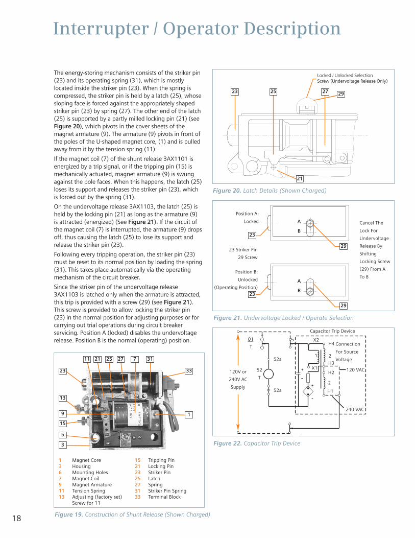
The energy-storing mechanism consists of the striker pin(23) and its operating spring (31), which is mostlylocated inside the striker pin (23). When the spring iscompressed, the striker pin is held by a latch (25), whosesloping face is forced against the appropriately shapedstriker pin (23) by spring (27). The other end of the latch(25) is supported by a partly milled locking pin (21) (seeFigure 20), which pivots in the cover sheets of themagnet armature (9). The armature (9) pivots in front ofthe poles of the U-shaped magnet core, (1) and is pulledaway from it by the tension spring (11).
If the magnet coil (7) of the shunt release 3AX1101 isenergized by a trip signal, or if the tripping pin (15) ismechanically actuated, magnet armature (9) is swungagainst the pole faces. When this happens, the latch (25)loses its support and releases the striker pin (23), whichis forced out by the spring (31).
On the undervoltage release 3AX1103, the latch (25) isheld by the locking pin (21) as long as the armature (9)is attracted (energized) (See Figure 21). If the circuit ofthe magnet coil (7) is interrupted, the armature (9) dropsoff, thus causing the latch (25) to lose its support andrelease the striker pin (23).
Following every tripping operation, the striker pin (23)must be reset to its normal position by loading the spring(31). This takes place automatically via the operatingmechanism of the circuit breaker.
Since the striker pin of the undervoltage release3AX1103 is latched only when the armature is attracted,this trip is provided with a screw (29) (see Figure 21).This screw is provided to allow locking the striker pin(23) in the normal position for adjusting purposes or forcarrying out trial operations during circuit breakerservicing. Position A (locked) disables the undervoltagerelease. Position B is the normal (operating) position.
Figure 19. Construction of Shunt Release (Shown Charged)
Capacitor Trip Device
120 VAC120V or
240V AC
Supply
01
T
52a
52
T
240 VAC
52a
5
1
X1
X2H4
2
Connection
For Source
VoltageH3
H2
2
H1
Figure 22. Capacitor Trip Device
Position A:
Locked
23 Striker Pin
29 Screw
Position B:
Unlocked
(Operating Position)
Cancel The
Lock For
Undervoltage
Release By
Shifting
Locking Screw
(29) From A
To B
Figure 21. Undervoltage Locked / Operate Selection
Figure 20. Latch Details (Shown Charged)
Locked / Unlocked SelectionScrew (Undervoltage Release Only)
1 Magnet Core3 Housing6 Mounting Holes 7 Magnet Coil9 Magnet Armature11 Tension Spring13 Adjusting (factory set)
Screw for 11
15 Tripping Pin21 Locking Pin 23 Striker Pin25 Latch27 Spring31 Striker Pin Spring33 Terminal Block
23 33
1
11 21 25 27 317
13
9
5
3
15
29
29
29
2523
21
23
A
B
A
B23
27

19
Interrupter / Operator Description
Capacitor Trip Device
The capacitor trip device is an auxiliary tripping optionproviding a short term means of storing adequateelectrical energy to ensure circuit breaker tripping.
This device is applied in circuit breaker installationslacking independent auxiliary control power or a stationbattery. In such installations, control power is usuallyderived from the primary source. In the event of aprimary source fault, or disturbance with resultingreduction of the primary source voltage, the capacitortrip device will provide short term tripping energy forcircuit breaker opening due to relay operation.
The capacitor trip includes a rectifier to convert the 120or 240 Vac control voltage to a dc voltage which is usedto charge a large capacitor to the peak of the convertedvoltage wave. See Figure 22.
Shock Absorber
Type GMSG circuit breakers are equipped with a sealed,oil-filled, viscous damper, or shock absorber (61.8)Figure 15. The purpose of this shock absorber is to limitovertravel and rebound of the vacuum interruptermovable contacts during the conclusion of an openingoperation. The shock absorber action affects only theend of an opening operation.
Secondary Disconnect
Signal and control power is delivered to the internalcircuits of the circuit breaker by an arrangement ofmovable contact fingers mounted on the side of thecircuit breaker. These fingers are shown in Figure 23.
When the circuit breaker is racked into the TEST orCONNECT positions in the metal-clad switchgear, thesedisconnect fingers engage a mating disconnect block onthe inside of the switchgear shown in Figure 24. These electrical connections automatically disengagewhen the circuit breaker is racked from the TEST to theDISCONNECT position.
All of the control power necessary to operate thecircuit breaker is connected to this disconnect blockinside the switchgear. The external trip and closecircuits and associated circuits are also connected tothe same disconnect block.
Auxiliary Switch
Figure 25 shows the circuit breaker mounted auxiliaryswitch. This switch provides auxiliary contacts for controlof circuit breaker closing and tripping functions. Contactsare available for use in relaying and external logiccircuits. This switch is driven by linkages connected tothe jack shaft. The auxiliary switch contains both 'b'(Normally Closed) and 'a' (Normally Open) contacts.When the circuit breaker is open, the 'b' switches areclosed and the 'a' switches are open.
MOC (Mechanism Operated Cell) Switch (optional)
Figures 26 and 27 show the principal components thatprovide optional control flexibility when operating thecircuit breaker in the TEST (optional) and CONNECT(standard) positions.
Figure 26 shows the MOC switch operating arm thatprojects from the right side of the circuit breaker,approximately centered vertically on the circuit breakerright side frame. The MOC switch operating arm is partof the jack shaft assembly and directly reflects the openor closed position of the circuit breaker primary contacts.
As the circuit breaker is racked into the appropriateposition inside the switchgear, the MOC switch operatingarm passes a wiring protective cover plate, and engagesthe pantograph linkage shown in Figure 27. Operationof the circuit breaker causes the pantograph linkage totransfer motion to the MOC switches located above thepantograph. The 'a' and 'b' contacts can be used inrelaying and control logic schemes.
All circuit breakers contain the MOC switch operatingarm. However, MOC switches are provided in theswitchgear only when specified.
Figure 23. Secondary Disconnects on Circuit Breaker
Figure 24. Secondary Disconnect Inside Switchgear

20
Interrupter / Operator Description
The circuit breaker engages the MOC auxiliary switch onlyin the CONNECT (operating) position unless an optionalTEST position pickup is specified in the contract. If a TESTposition pickup is included, the circuit breaker will engagethe auxiliary switch in both positions. Up to 24 stages maybe provided.
TOC (Truck Operated Cell) Switch
Figure 27 shows the optional TOC cell switch. Thisswitch is operated by the circuit breaker as it is rackedinto the CONNECT position.
Various combinations of 'a' and 'b' contacts may beoptionally specified. These switches provide control andlogic indication that a circuit breaker in the cell hasachieved the CONNECT (ready to operate) position.
Trip-Free Interlock
Figure 28 shows the devices providing the trip-freeinterlock function. The purpose of the trip-free interlock isto hold the circuit breaker operating mechanismmechanically and electrically trip-free. The circuit breakeris held trip-free during racking and whenever the circuitbreaker is between the TEST and CONNECT positionswithin the switchgear enclosure. This interlock ensuresthat the circuit breaker primary contacts can only beclosed when in the CONNECT position, or the TESTposition, or out of the switchgear cell.
Rating Interlock
Figure 28 shows the rating interlock interference platesmounted on the circuit breaker frame. The circuit breakerinterference plates are complemented by matching plateslocated in the cubicle.
The interference plates (rating interlocks) test the circuitbreaker voltage, continuous current, and interrupting andmomentary ratings and will not allow circuit breakerinsertion unless the circuit breaker ratings match orexceed the cell rating.
Circuit Breaker Frame
The frame of the GMSG circuit breaker contains severalimportant devices and features deserving of specialattention. These are the ground disconnect, the fourracking wheels and four handling wheels.
Figure 25. Auxiliary Switch
Figure 27. MOC and TOC Switches and AssociatedTerminal Blocks
Figure 26. MOC Switch Operating Arm on Circuit Breaker

21
Interrupter / Operator Description
Ground Disconnect
Figure 28 shows the ground disconnect contact mountedat the bottom of the circuit breaker. The spring loadedfingers of the disconnect contact engage the ground bar(Figure 29) at the bottom of the switchgear assembly.The ground bar is to the left of the racking mechanism,shown at the bottom center of the switchgear.
Circuit Breaker Handling Wheels
The type GMSG circuit breaker is designed for easymovement into and out of the metal-clad switchgearassembly. A section of indoor or Shelter-Clad switchgeardoes not require a transfer truck or lifting truck forhandling of the circuit breaker when all circuit breakersare located at floor level. Once the circuit breaker isracked out of the switchgear, the unit can be pulled usingthe handles on the front of the circuit breaker. The circuitbreaker will roll on its bottom four wheels.
When circuit breakers are located above floor level,handling of the circuit breakers requires the use of alifting device or a crane with a lift sling.
Racking Mechanism
Figure 29 shows the racking mechanism in theswitchgear used to move the circuit breaker between theDISCONNECT, TEST and CONNECT positions. Thismechanism contains a circuit breaker Racking Block thatmates with the bottom of the circuit breaker housing,and locks the circuit breaker to the racking mechanismduring in and out movement. A racking crank (notshown) mates to the square shaft of the rackingmechanism. Clockwise rotation of the crank moves thecircuit breaker into the switchgear, and counterclockwiserotation removes it.
The racking and trip-free interlocks provide severalessential functions.1. They prevent racking a closed circuit breaker into or
out of the switchgear assembly.
2. They discharge the closing springs whenever thecircuit breaker is inserted into, or withdrawn from, the switchgear.
3. They prevent closing of the circuit breaker unless it isin either the TEST or CONNECT positions, and theracking crank is not engaged.
The rating interlock prevents insertion of a lower ratedcircuit breaker into a cubicle intended for a circuit breakerof higher ratings.
Figure 28. Circuit Breaker Interlocks and Ground Disconnect
Figure 29. Circuit Breaker Compartment (MOC/TOCSwitch Cover Removed for Photo)
A. Ground disconnectB. Racking mechanism
release handleC. Trip-free interlock
D. Closed-breaker rackinginterlock
E. Circuit breaker frameF. Rating interlock
A E B C D F
A. Interference blockingplate (rating interlock)
B. Racking mechanismC. Ground barD. Guide railsE. Trip-free and racking
interlock padlock provisions
F. MOC switch operatorG. MOC switch terminalsH. TOC switch terminalsI. Shutter operating linkageJ. Shutter (behind barrier)K. CT barrierL. Secondary disconnect
A DEBCD
I
L
J K
H
G
F
I

22
Vehicle Description
Vehicle Function and Operational Interlocks
Type GM-SG vacuum circuit breakers are comprised mainlyof the interrupter/operator module fitted to a vehicle. Thisinterrupter/operator module is an integral arrangement ofoperating mechanism, dielectric system, vacuuminterrupters, and means of connecting the primary circuit.The vehicle supports the interrupter/operator module,providing mobility and fully coordinated application inSiemens type GM-SG switchgear.
Successful coordinated application of the fully assembledGMSG vacuum circuit breaker is achieved through precisealignment in fixtures during manufacture, and importantfunctional interlocking.
Alignment
All aspects of the circuit breaker structure which impactalignment and interchangeability are checked usingmaster fixtures at the factory. Field adjustment will notnormally be required.
Interlocks
Circuit Breaker Racking Interlocks
The interrupter/operator module and the vehicle portions ofthe circuit breaker, and the racking mechanism in theswitchgear all cooperate to provide important operationalinterlocking functions.
1. Rating InterlockThe rating interlock consisting of a coded interferenceplate is mounted on the vehicle as shown in Figure 28.A mating interference blocking plate is mounted in thedrawout compartment as seen in Figure 29. The twoplates are mounted in alignment and must pass througheach other in order for the circuit breaker vehicle toenter the drawout compartment. The interlock is codedto test rated voltage, as well as interrupting andcontinuous current ratings. The circuit breaker mustequal or exceed all of the cubicle ratings in order toenter the compartment.
2. Racking Interlocks
a. Closed Circuit Breaker Interlock - Figure 28shows the location of the closed circuit breakerinterlock plunger on the circuit breaker frame.The purpose of this interlock is to positively blockcircuit breaker racking operations whenever thecircuit breaker is closed. The plunger is coupledto the jack shaft as seen in Figure 15, 63. Whenthe jack shaft rotates 60 degrees to close, theinterlock plunger is driven straight downwardbeneath the frame of the circuit breaker.
The downward projecting plunger blocks rackingoperation when the circuit breaker is closed. Figure29 shows the racking mechanism located on thefloor in the center of the circuit breakercompartment. Note the two "wing-like" elementsthat project from the right side of the rackingmechanism. The closed circuit breaker interlockplunger, when down (circuit breaker closed), fallsbehind the front wing in the TEST position andbehind the rear wing in the CONNECT position.
The wings are coupled to the element of the rackingmechanism which shrouds the racking screw. Thisshroud must be moved rearward to insert the rackingcrank socket in order to engage the racking shaft.With the plunger down (circuit breaker closed), thewings and shroud cannot be moved and thus rackingis blocked.
b. Spring Dump/Trip-Free InterlockFigure 28 shows the automatic closing spring energyrelease (spring dump) and trip-free interlock. Thisinterlock is a plunger with a roller on the lower end.The plunger roller tracks the shape of the springdischarge and trip-free cam profiles on the rackingmechanism in the switchgear (Figure 29).
The spring dump cam profile on the rackingmechanism raises the spring dump/trip-free interlockupon insertion of the circuit breaker into thecompartment, or upon withdrawal from thecompartment. The interlock is raised at about thetime the front wheels pass over the cubicle sill. Itallows the spring dump interlock to be in the reset(lowest) position at all other times.
The trip-free cam profile on the racking mechanismallows the spring dump/trip-free racking interlock tobe in the lowest position (reset) only when the circuitbreaker is in the TEST or the CONNECT position.Thus, during racking, the trip-free/spring dumpinterlock is held in an elevated condition exceptwhen the circuit breaker reaches the TEST or theCONNECT position. The circuit breaker can be closedonly when the interlock plunger is down, and will tripif the plunger is moved up.
Hazardous voltage and high-speed moving parts.
Will cause death, serious injury, andproperty damage.
Do not by-pass interlocks or otherwise makeinterlocks inoperative. Interlocks must be inoperation at all times.
Read this instruction manual. Know andunderstand correct interlock function. Checkinterlock function prior to inserting circuitbreaker into switchgear cubicle.

23
Vehicle Description
Figure 30 shows the operating mechanism detailcomponents which establish a spring dumpcondition as the spring dump/trip-free interlock isactuated by the spring dump and trip-free camprofiles on the racking mechanism. The risingplunger raises a lever attached to the base of theoperating mechanism enclosure. This lever raises thetrip-free pushrod, which raises the closing springrelease cam. This blocks closing of the circuit breakerwhile the circuit breaker is being racked.
c. Trip-Free Interlock Position Mechanical Interlock
In order to prevent the motor charging circuit from"making and breaking" as the circuit breaker andcubicle secondary disconnects make or breakphysical contact, an electrical switch is provided.
This switch is mounted in the line of action takenby the trip-free interlock plunger which follows theracking mechanism cam and is elevated at all timesthe circuit breaker is in the drawout compartmentexcept when in the TEST or CONNECT positions. Astriker plate, integral with the trip-free interlockplunger, engages and operates (opens) the switchwhen the plunger is in an elevated positionblocking spring charging motor operation. Theswitch is closed when the circuit breaker occupiesthe TEST or CONNECT position, allowing thecharging motor to operate automatically.
Figure 30. Closed Circuit Breaker Interlock Mechanisms in Stored Energy Mechanism
Close Latch Lever
Closing Spring Release Cam
Trip Free Pushrod
Interlock Levers
Trip Latch Lever
Spring Dump Lever
Normal Operating Position
Rear
of E
nclo
sure

24
Maintenance
Introduction and Maintenance Intervals
Periodic inspections and maintenance are essentialto obtain safe and reliable operation of the typeGMSG circuit breaker.
When type GMSG circuit breakers are operated under"Usual Service Conditions", maintenance andlubrication is recommended at ten year intervals orat the number of operations indicated in Table 2."Usual" and "Unusual" service conditions for MediumVoltage Metal-Clad Switchgear are defined inANSI/IEEE C37.20.2, section 8.1 and C37.04, section4 together with C37.010, section 4. Generally, "usualservice conditions" are defined as an environment inwhich the equipment is not exposed to excessivedust, acid fumes, damaging chemicals, salt air, rapidor frequent changes in temperature, vibration, highhumidity, and extremes of temperature.
The definition of "usual service conditions" is subjectto a variety of interpretations. Because of this, youare best served by adjusting maintenance andlubrication intervals based on your experience withthe equipment in the actual service environment.
Regardless of the length of the maintenance andlubrication interval, Siemens recommends that circuitbreakers should be inspected and exercised annually.
For the safety of maintenance personnel as well asothers who might be exposed to hazards associatedwith maintenance activities, the safety related workpractices of NFPA 70E should always be followedwhen working on electrical equipment. Maintenancepersonnel should be trained in the safety practices,procedures and requirements that pertain to theirrespective job assignments. This manual should bereviewed and retained in a location readily accessiblefor reference during maintenance of this equipment.
The user must establish a periodic maintenanceprogram to ensure trouble-free and safe operation.The frequency of inspection, periodic cleaning, andpreventive maintenance schedule will depend uponthe operation conditions. NFPA Publication 70B,"Electrical Equipment Maintenance" may be used as aguide to establish such a program. A preventivemaintenance program is not intended to coverreconditioning or major repair, but should be designedto reveal, if possible, the need for such actions in timeto prevent malfunctions during operation.
Recommended Hand Tools
Type GMSG circuit breakers use both standard SAE (UScustomary) and metric fasteners. Metric fasteners areused for the vacuum interrupters and in theinterrupter/operator module. SAE (US customary)fasteners are used in most other locations. This list ofhand tools describes those normally used indisassembly and re-assembly procedures.
Metric• Sockets and open end wrenches: 7, 8, 10, 13, 17,
19 and 24mm
• Hex keys: 5, 6, 8 and 10mm
• Deep Sockets: 19mm
• Torque Wrench: 0 - 150 Nm (0 - 100 ft-lbs)
SAE (US Customary)• Socket and Open-End Wrenches: 5/16, 3/8, 7/16,
1/2, 9/16, 11/16, 3/4, and 7/8 in.
• Hex Keys: 3/16 and 1/4 in.
• Screwdrivers: 0.032 x 1/4 in. wide and 0.055 x7/16 in. wide
• Pliers
• Light Hammer
• Dental Mirror
• Flashlight
• Drift Pins: 1/8, 3/16, and 1/4 in.
• Retaining Ring Pliers (external type, tip diameter0.038 in.)
Recommended Maintenance and Lubrication
Periodic maintenance and lubrication shouldinclude all the tasks shown in Table 1.Recommended procedures for each of the listedtasks are provided in this section of the manual.
Hazardous voltage and high-speed moving parts.
Will cause death, serious injury, and property damage.
Read instruction manuals, observe safetyinstructions and limit use to qualified personnel.
Failure to maintain the equipment could result in death,serious injury or product failure, and can preventsuccessful functioning of connected apparatus.
The instructions contained herein should be carefully reviewed,understood, and followed.
The maintenance tasks in Table 1 must be performed regularly.

25
Maintenance
The list of tasks in Table 1 does not represent anexhaustive survey of maintenance steps necessaryto ensure safe operation of the equipment.Particular applications may require furtherprocedures. Should further information be desiredor should particular problems arise which are notcovered sufficiently for the Purchaser's purposes,the matter should be referred to Siemens at 1-800-347-6659 (919-365-2200 outside the U.S.).
Removal from Switchgear
Prior to performing any inspection or maintenancechecks or tests, the circuit breaker must beremoved from the switchgear. The Installation andInitial Functional Tests section describes theremoval procedure in detail. Principal steps arerepeated here for information and guidance, butwithout the details of the preceding section.
1. The first step is to de-energize the circuit breaker.Figure 31 illustrates the location of the trip controlon the circuit breaker operator panel. Depressingthe Trip pushbutton opens the circuit breaker priorto removal from the switchgear.
2. The second step in the removal procedure is to de-energize control power to the circuit breaker.Open the control power disconnect device.
3. Rack the circuit breaker to the DISCONNECT position.
4. Perform the spring discharge check. This is done byfirst depressing the red Trip pushbutton. Second,depress the black Close pushbutton. Third, depressthe red Trip pushbutton again, and observe thespring condition indicator. It should read Discharge.Figure 31 shows the circuit breaker spring conditionindicator in the Discharged position.
• Checks of the primary power path
• Cleanliness check
• Inspection of primary disconnects
• Checks of the stored energy operator mechanism
• Maintenance and lubrication
• Fastener check
• Manual spring charging check
• Contact erosion check
• Electrical control checks
• Wiring and terminals check
• Secondary disconnect check
• Automatic spring charging check
• Electrical close and trip check
• Vacuum integrity check
• High potential test
• Insulation test
• Contact resistance test
• Inspection and cleaning of circuit breaker insulation
• Functional tests
The use of unauthorized parts in the repair of theequipment, or tampering by unqualified personnel willresult in dangerous conditions which will cause death,serious injury or equipment damage.
Follow all safety instructions contained herein.
Table 1. Maintenance Tasks
Figure 31. Manual Tripping of Circuit Breaker
Figure 32. GMSG Circuit Breaker Showing VacuumInterrupters and Primary Disconnects (Barriers Removed)

26
5. Remove the circuit breaker from the switchgear.Refer to the preceding installation section of thismanual for special instructions and precautionsregarding removal of a circuit breaker which is notat floor level.
6. The circuit breaker can be located either on the flooror on a pallet. Each circuit breaker has four wheelsand handles to allow one person to maneuver theunit on a level surface without assistance.
Checks of the Primary Power Path
The primary power path consists of the three vacuuminterrupters, the three upper and the three lowerprimary disconnects. These components are checkedfor cleanliness and condition. The vacuum interruptersare also checked for vacuum integrity.
Some test engineers prefer to perform the contacterosion check during the manual spring charging checkof the operator, since charging of the springs isnecessary to place the contacts in the closed position.Also, the vacuum integrity check is usually performedin conjunction with the High Potential tests.
These instructions follow the recommendation thatthese tests (contact erosion/manual spring chargingcheck, and vacuum integrity/high potential tests) willbe combined as described.
Cleanliness Check
Figure 32 is a side view of the GMSG circuit breaker withthe insulating barriers removed to show the vacuuminterrupter, and the upper and lower primary disconnects.
All of these components must be cleaned and free ofdirt or any foreign objects. Use a dry lint-free cloth. For stubborn dirt, use a clean cloth saturated withisopropyl alcohol (except for the vacuum interrupters).For stubborn dirt on a vacuum interrupter, use a clothand warm water and a small amount of mild liquidhousehold detergent as a cleaning agent. Drythoroughly using a dry lint-free cloth.
Inspection of Primary Disconnects
Figure 33 shows the primary disconnect contactfingers engaged. When the contacts are mated withthe switchgear primary stud assembly, there is forcefulcontact distributed over a wide area. This maintainslow current flow per individual contact finger.
Inspect the contact fingers for any evidence of burningor pitting that would indicate weakness of the contactfinger springs.
Inspect the primary disconnect arms for physicalintegrity and absence of mechanical damage.
Inspect the flexible connectors that connect thebottom movable contacts of the vacuum interrupters tothe lower primary disconnect arms for tightness andabsence of mechanical damage, burning, or pitting.
Using a clean cloth saturated with isopropyl alcohol,clean old lubricant from primary disconnects, andapply a very thin layer of Siemens contact lubricant(reference 15-172-791-233).
Checks of the Stored Energy Operator Mechanism
The stored energy operator checks are divided intomechanical and electrical checks for simplicity and betterorganization. This first series of checks determine if thebasic mechanism is clean, lubricated and operatessmoothly without control power. The contact erosioncheck of the vacuum interrupter is also performedduring these tasks.
Maintenance and Lubrication
Table 2 gives the recommended maintenance intervalsfor circuit breakers. These intervals assume that thecircuit breaker is operated under “usual serviceconditions” as discussed in ANSI/IEEE C37.20.2, section8.1, and C37.04, section 4, together with C37.010,section 4. The maintenance and lubrication interval isthe lesser of the number of closing operations or thetime interval since last maintenance.
The interrupter operator mechanism is shown in Figure34 with the front cover and the operator control panelremoved to show construction details. Both thetripping spring and the closing spring are shown. Themovable end of the closing spring is connected to acrank arm. The movable end of the opening spring isconnected to the jack shaft by a pull rod.
Clean the entire stored energy operator mechanismwith a dry, lint-free cloth.
Check all components for evidence of excessive wear.Place special attention upon the closing spring crankand the various pushrods and linkages.
Maintenance
Figure 33. Primary Disconnect in Mated Position
Table 2. Maintenance and Lubrication Schedule
Circuit Breaker
Type
Number of Years / Closing Operations
(whichever comes first)
GMSG 10 years /10,000 operations

27
Maintenance
Figure 34. Lubrication of Operator Mechanism
Beacon 325
Anderol 732
Typical for all3 phases
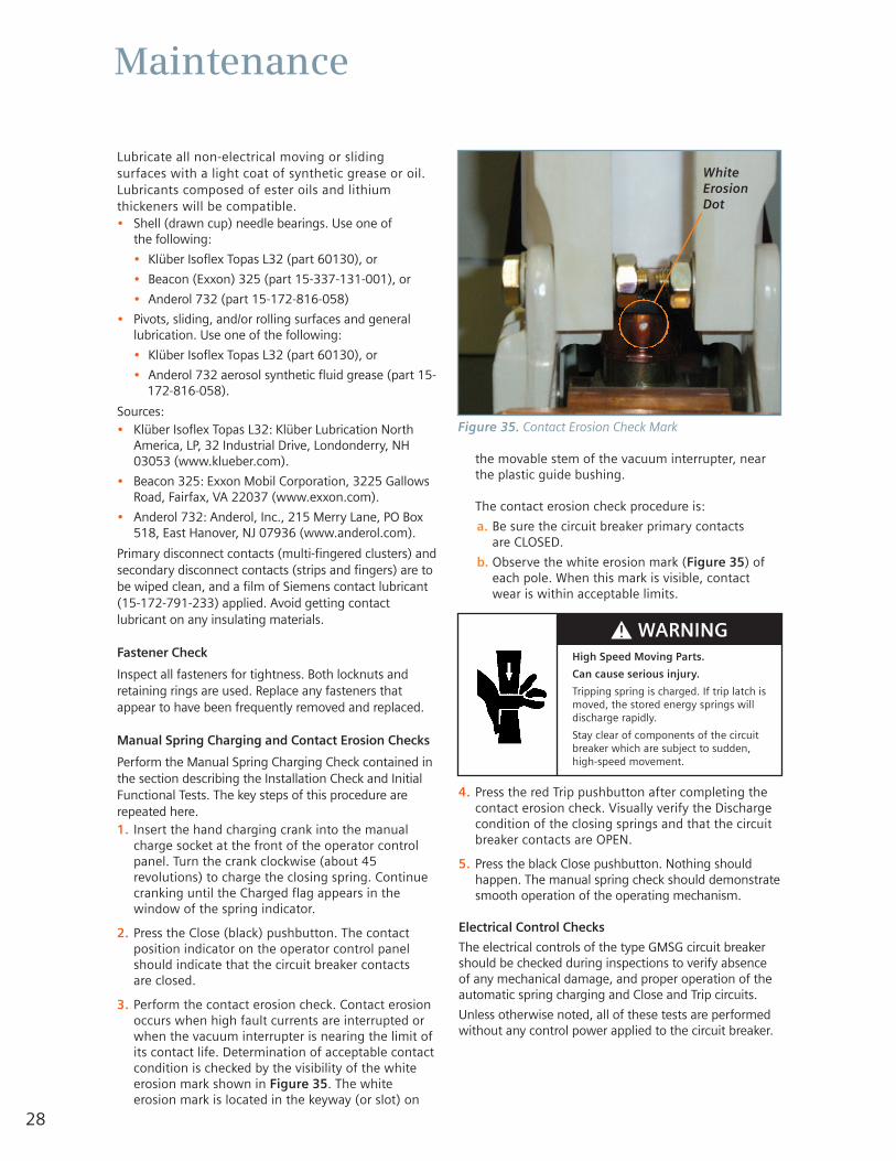
28
Maintenance
Lubricate all non-electrical moving or slidingsurfaces with a light coat of synthetic grease or oil.Lubricants composed of ester oils and lithiumthickeners will be compatible.• Shell (drawn cup) needle bearings. Use one of
the following:
• Klüber Isoflex Topas L32 (part 60130), or
• Beacon (Exxon) 325 (part 15-337-131-001), or
• Anderol 732 (part 15-172-816-058)
• Pivots, sliding, and/or rolling surfaces and generallubrication. Use one of the following:
• Klüber Isoflex Topas L32 (part 60130), or
• Anderol 732 aerosol synthetic fluid grease (part 15-172-816-058).
Sources:• Klüber Isoflex Topas L32: Klüber Lubrication North
America, LP, 32 Industrial Drive, Londonderry, NH03053 (www.klueber.com).
• Beacon 325: Exxon Mobil Corporation, 3225 GallowsRoad, Fairfax, VA 22037 (www.exxon.com).
• Anderol 732: Anderol, Inc., 215 Merry Lane, PO Box518, East Hanover, NJ 07936 (www.anderol.com).
Primary disconnect contacts (multi-fingered clusters) andsecondary disconnect contacts (strips and fingers) are tobe wiped clean, and a film of Siemens contact lubricant(15-172-791-233) applied. Avoid getting contactlubricant on any insulating materials.
Fastener Check
Inspect all fasteners for tightness. Both locknuts andretaining rings are used. Replace any fasteners thatappear to have been frequently removed and replaced.
Manual Spring Charging and Contact Erosion Checks
Perform the Manual Spring Charging Check contained inthe section describing the Installation Check and InitialFunctional Tests. The key steps of this procedure arerepeated here.1. Insert the hand charging crank into the manual
charge socket at the front of the operator controlpanel. Turn the crank clockwise (about 45revolutions) to charge the closing spring. Continuecranking until the Charged flag appears in thewindow of the spring indicator.
2. Press the Close (black) pushbutton. The contactposition indicator on the operator control panelshould indicate that the circuit breaker contacts are closed.
3. Perform the contact erosion check. Contact erosionoccurs when high fault currents are interrupted orwhen the vacuum interrupter is nearing the limit ofits contact life. Determination of acceptable contactcondition is checked by the visibility of the whiteerosion mark shown in Figure 35. The whiteerosion mark is located in the keyway (or slot) on
the movable stem of the vacuum interrupter, nearthe plastic guide bushing.
The contact erosion check procedure is:
a. Be sure the circuit breaker primary contacts are CLOSED.
b. Observe the white erosion mark (Figure 35) ofeach pole. When this mark is visible, contactwear is within acceptable limits.
4. Press the red Trip pushbutton after completing thecontact erosion check. Visually verify the Dischargecondition of the closing springs and that the circuitbreaker contacts are OPEN.
5. Press the black Close pushbutton. Nothing shouldhappen. The manual spring check should demonstratesmooth operation of the operating mechanism.
Electrical Control Checks
The electrical controls of the type GMSG circuit breakershould be checked during inspections to verify absenceof any mechanical damage, and proper operation of theautomatic spring charging and Close and Trip circuits.
Unless otherwise noted, all of these tests are performedwithout any control power applied to the circuit breaker.
Figure 35. Contact Erosion Check Mark
High Speed Moving Parts.
Can cause serious injury.
Tripping spring is charged. If trip latch ismoved, the stored energy springs willdischarge rapidly.
Stay clear of components of the circuitbreaker which are subject to sudden,high-speed movement.
White ErosionDot

29
Maintenance
Check of the Wiring and Terminals
1. Physically check all of the circuit breaker wiringfor evidence of abrasion, cuts, burning ormechanical damage.
2. Check all terminals to be certain they are solidlyattached to their respective device.
Check of the Secondary Disconnect
In addition to checking the terminals of the secondarydisconnect, the secondary contact fingers need to befree to move without binding. Depress each finger,confirm presence of spring force (contact pressure), andverify freedom of motion.
Automatic Spring Charging Check (Control Power Required)
Repeat the automatic spring charging check described inthe section entitled Installation Checks and InitialFunctional Tests.
Primary tasks of this check are:
1. The circuit breaker is energized with control power forthis check.
2. De-energize the source of control power.
3. Install the circuit breaker end of the split plugjumper over the secondary disconnect of the circuitbreaker. The split plug jumper has one male andone female connector and cannot be installedincorrectly (Figure 5).
4. Install the switchgear end of the plug jumper over thesecondary disconnect block inside the switchgear(Figure 6).
5. Energize the control power source.
6. When control power is connected to the circuit breaker,the closing springs should automatically charge.Visually verify that the closing springs are charged.
Electrical Close and Trip Check (Control Power Required)
A check of the circuit breaker control circuits is performedwhile the unit is still connected to the switchgear by theplug jumper. This check is made with the circuit breakerenergized by control power from the switchgear.
1. Once the circuit breaker springs are charged, move theswitchgear Close/Trip switch to the Close position.There should be both the sound of the circuit breakerclosing and indication that the circuit breaker contactsare closed by the main contact status indicator.
2. As soon as the circuit breaker has closed, theautomatic spring charging process is repeated.
3. After a satisfactory close operation is verified, movethe switchgear Close/Trip switch to the Trip position, orsend a trip command from a protective relay. Verify byboth sound and contact position that the contacts areopen. Completion of these checks demonstratessatisfactory operation of auxiliary switches, internalrelays and solenoids.
Checks of the Spring Charging Motor
No additional checks of the spring charging motor are necessary.
Vacuum Interrupters
The life expectancy of vacuum interrupters is afunction of the number of interruptions and magnitudeof current interrupted.
They must also be replaced at 10,000 mechanicaloperations or when the contacts have been erodedbeyond allowed limits. Vacuum interrupterreplacement procedures are detailed in the followingmaintenance instructions.
The curve shown in Figure 36 is offered as a guide tolife expectancy.
Hazardous voltage and high-speed mechanical parts.
Will cause death, serious injury, and property damage.
Read instruction manuals, observe safetyinstructions and limit use to qualified personnel.
Note: A temporary source of control power and testleads may be required if the control power source hasnot been connected to the switchgear. When controlpower is connected to the type GMSG circuit breaker,the closing springs should automatically charge.

33
Breaking Current (Sym. Value)Load Graph “A” Vacuum Interrupter Type VS-17006
Perm
issi
ble
Op
erat
ing
Cyc
les
50,000
100,000
20,000
10,000
5,000
2,000
1,000
500
200
100
50
20
101 2 5 10 20 50 100kA
Breaking Current (Sym. Value)Load Graph “B” Vacuum Interrupter Type VS-15052
Perm
issi
ble
Op
erat
ing
Cyc
les
50,000
100,000
20,000
10,000
5,000
2,000
1,000
500
200
100
50
20
101 2 5 10 20 50 100kA
1823
25
29
31.5
36
3
12
4
5
28
(28kA) 8
31.5
(31.5kA) 12
(33kA) 7
33
11(50kA)
40
10(40kA)
41
6(44kA)
30
Maintenance
Figure 37. Lower pole Support with Insulated Coupler
Figure 38. Primary Contact Closed - Insulated Coupler Disconnected
Figure 36. Typical Vacuum Interrupter Contact Curve Line
Interrupter Vacuum Check Mechanical (Figures 37-39)
Before putting the circuit breaker into service, or if aninterrupter is suspected of leaking as a result ofmechanical damage, perform a vacuum integrity checkeither mechanically as described in this section, oralternatively, electrically using a high potential test setas described in the next section.
Open and isolate the circuit breaker and detach theinsulated coupler (48) from lever (48.6) (Figure 37).
The atmospheric pressure will force the movingcontact of a hermetically sealed interrupter into the"Closed" position, causing lever (48.6) to move intothe position shown in Figure 38.
A vacuum interrupter may be assumed to be intact ifit shows the following characteristics:
An appreciable closing force has to be overcomewhen lever (48.6) is moved to the "Open" position byhand Figure 39. When the lever is released, it mustautomatically return to the "Closed" position with anaudible sound as the contacts touch.
After vacuum integrity check, reconnect the lever(48.6) to the insulated coupler (48).
48 48.6
48 48.6

31
Maintenance
High-Potential Tests
The next series of tests (Vacuum Integrity Test andInsulation Tests) involve use of high voltage testequipment. The circuit breaker under test should beinside a suitable test barrier equipped with warning lights.
Vacuum Integrity Check (using Dielectric Test)
A high potential test is used to verify the vacuumintegrity of the circuit breaker. The test is conductedon the circuit breaker with its primary contacts in theOpen position.
High Potential Test Voltages
The voltages for high potential tests are shown inTable 3.
Vacuum Integrity Test Procedure1. Observe safety precautions listed in the danger and
warning advisories. Construct the proper barrier andwarning light system.
2. Ground each pole not under test.
3. Apply test voltage across each pole for one minute(circuit breaker open).
4. If the pole sustains the test voltage for that period, itsvacuum integrity has been verified.
As-Found Insulation and Contact Resistance Tests
As-Found tests verify the integrity of the circuit breakerinsulation system. Megger* or insulation resistance testsconducted on equipment prior to installation provide abasis of future comparison to detect changes in theprotection afforded by the insulation system. Apermanent record of periodic As-Found tests enables themaintenance organization to determine when correctiveactions are required by watching for significantdeterioration in insulation resistance, or increases incontact resistance.
(*Megger is a registered trademark of Megger Group, Ltd.)
Figure 39. Primary Contact Closed Forced Open byManual Pressure
High Potential tests employ hazardous voltages.
Will cause serious injury and death.
Follow safe procedures, exclude unnecessarypersonnel and use safety barriers. Keep awayfrom the circuit breaker during application oftest voltages. Disconnect the plug jumper frombetween the circuit breaker and switchgearbefore conducting high potential tests.
Vacuum interrupters may emit X-ray radiation.
Can cause serious injury.
Keep personnel more than six (6) feetaway from a circuit breaker under test.
X-rays can be produced when a highvoltage is placed across two circuitelements in a vacuum.
Table 3. High Potential Test Voltages
Note: Do not use DC high potential testersincorporating half-wave rectification. Thesedevices produce high peak voltages.
High peak voltages will produce X-ray radiation. DCtesters producing excessive peak voltages also showerroneous readings of leakage current when testingvacuum circuit breakers.
Note: This test includes not only the vacuuminterrupter, but also the other insulation componentsin parallel with the interrupter. These include thestandoff insulators and the insulated drive links, aswell as the insulating (tension) struts between theupper and lower vacuum interrupter supports. If theseinsulation components are contaminated or defective,the test voltage will not be sustained. If so, clean orreplace the affected components, and retest.
RatedMaximum
VoltagekV (rms)
PowerFrequencyWithstandkV (rms)
Field Test Voltage
kV (rms) kV (dc)
4.76 19 14.25 20.2
8.25 36 27 38.2
15 36 27 38.2

32
Maintenance
Insulation and Contact Resistance Test Equipment
In addition to the High Potential Test Equipment capableof test voltages as listed in Table 3, the followingequipment is required:• AC High Potential tester with test voltage of 1500
volts, 60 Hz• Test equipment for contact resistance tests.
Insulation and Contact Resistance Test Procedure1. Observe safety precaution listed in the danger
and caution advisories for the Vacuum IntegrityCheck tests.
2. Close the circuit breaker. Ground each pole notunder test. Use manual charging, closing andtripping procedures.
3. Apply the proper ac or dc high potential test voltageas shown in Table 3 between a primary conductorof the pole and ground for one minute.
4. If no disruptive discharge occurs, the insulationsystem is satisfactory.
5. After test, ground both ends and the center metalsection of each vacuum bottle to dissipate anystatic charge.
6. Disconnect the leads to the spring charging motor.
7. Connect all points of the secondary disconnect with ashorting wire. Connect the shorting wire to the highpotential lead of the high voltage tester, and groundthe circuit breaker housing. Starting with zero volts,gradually increase the test voltage to 1500 volts rms,60 Hz. Maintain test voltage for one minute.
8. If no disruptive discharge occurs, the secondarycontrol insulation level is satisfactory.
9. Disconnect the shorting wire and re-attach the leadsto the spring charging motor.
10. Perform contact resistance tests of the primarycontacts. Refer to Figure 40. Contact resistanceshould not exceed the values listed in Table 4.
Inspection and Cleaning of Circuit Breaker Insulation1. Perform the Spring Discharge Check on the circuit
breaker after all control power is removed. TheSpring Discharge Check consists of 1) depressing thered Trip pushbutton, 2) then depressing the blackClose pushbutton, and 3) again depressing the redTrip pushbutton. All of these controls are on thecircuit breaker front panel. Visually verify theDISCHARGE condition of the springs.
2. Remove phase barriers as shown in Figure 7.
3. Clean barriers and post insulators using clean clothdipped in isopropyl alcohol.
4. Replace all barriers. Check all visible fasteners againfor condition and tightness.
Functional Tests
Refer to the Installation Checklist in the InstallationChecks and Initial Functional Tests section of thismanual. Functional tests consist of performing at leastthree (3) Manual Spring Charging Checks and three (3)Automatic Spring Charging Checks. After these tests arecomplete, and the springs fully discharged, all fastenersand connections are checked again for tightness andcondition before re-installing the circuit breaker into themetal-clad switchgear.
Figure 40. Contact Resistance Test of the Primary Contacts
Table 4. Maximum Contact Resistance
Current Rating(Amps)
25KAContact
Resistance(Micro-Ohms)
OthersContact
Resistance(Micro-Ohms)
120020003000
4035--
353030
Note: Do not use any cleaning compoundscontaining chlorinated hydrocarbons such as trichlorethylene, perchlorethylene or carbon tetrachloride.
These compounds will damage the phenylene ethercopolymer material used in the barriers and otherinsulation on the circuit breaker.

33
Overhaul
Introduction
For following procedures along with the troubleshootingcharts at the end of this section, provide maintenancepersonnel with a guide to identifying and correctingpossible malfunctions of the type GMSG vacuum circuit breaker.
Circuit Breaker Overhaul
Table 5 gives the recommended overhaul schedule fortype GMSG circuit breakers. These intervals assume thatthe circuit breaker is operated under “usual serviceconditions” as discussed in ANSI/IEEE C37.20.2, section8.1, and ANSI/IEEE C37.04, section 4, and elaborated inC37.010, section 4. If the circuit breaker is operatedfrequently, the overhaul interval in Table 5 may coincidewith the maintenance interval in Table 2.
When actual operating conditions are more severe,overhaul periods should occur more frequently. The counter on the front panel of the circuit breakerrecords the number of operations.
Replacement at Overhaul
The following components are replaced during an overhaul of the circuit breaker, when required:• Vacuum interrupters as determined by
vacuum integrity test, contact erosion, or after 10,000 operations.
• Spring Release Coil, 52SRC
• Shunt Trip Coil, 52T
• Auxiliary Switch
When these parts are changed, locking devices must alsobe removed and replaced. These include lock washers,retaining rings, retaining clips, spring pins, cotter pins, etc.1. Replace Vacuum Interrupter, instructions follow.
2. Spring Release Coil (52SRC) or Shunt Trip Coil (52T).
a. Remove two "push on" terminal connections
b. Remove two M4 hex head screws and dismountsolenoid, drawing it towards you.
c. Install replacement solenoids with two M4 hexhead screws and replace "push on" terminals.
d. Solenoid mounting screws must be installed usingthread locking adhesive (Loctite #222, Siemenspart 15-133-281-007) and primer (Loctite primerT, Siemens part 15-133-281-005).
3. Lubricate operating mechanism in accordance withinstructions which follow.
4. When work is finished, operate circuit breaker,close/open several times, and check that all screwconnections are tight.
Replacement of Vacuum Interrupters
Replacement interrupters are furnished as a completeassembly. They have been completely tested andmechanically conditioned.
It is recommended that one interrupter be removed andreplaced completely rather than removing two or moreinterrupters at a time. The following procedure in checklist format describes the procedure for removing andreplacing a vacuum interrupter. Components may beidentified by reference to Figures 41 and 42.
1. Removing the Interrupter
1.1 Before starting work, the circuit breaker shouldbe isolated from all primary and control powersources and all stored energy discharged bytripping, closing, and tripping the circuitbreaker by hand. Discharge any static charge by grounding both ends and the center metalsection of the vacuum interrupter. Carefullyremove phase barriers.
1.2 Loosen the lateral bolt(s) on terminal clamp(29.2). Refer to Figure 42 and employ theillustrated procedure to loosen clamp hardware.(6 or 8mm hex key and 13 or 16mm socket).
1.3 Withdraw pin (48.5) from insulating coupler(48) and levers (48.6).
1.4 Remove coupling pin from the eye bolt (36.3)
Table 5. Overhaul Schedule
Circuit Breaker TypeNumber of Closing
Operations
GMSG 10,000
Note: Special care needs to be exercised in removalor installation of hardware around the bottom, ormovable contact end, of the vacuum interrupter.
The movable contact uses a metal bellows to maintainthe vacuum seal while still permitting up and downmotion of the contact. This bellows is rugged andreliable, and is designed to withstand years of verticalmovement. However, care should be exercised toavoid subjecting the bellows to excessive torqueduring removal and replacement. Twisting the bellowsthrough careless bolt removal or tightening maydamage the vacuum interrupter.
Hazardous voltages and high speed moving parts.
Can cause death, serious injury, or property damage.
Read instruction manual. All work must beperformed with the circuit breaker completely de-energized and the springs discharged. Limitwork to qualified personnel.

34
Overhaul
1.5 Free struts (28) from the upper pole support(20). Loosen the strut hardware on the lowersupport (40) and swing the struts forward anddownward (16mm open end wrench and16mm socket).
1.6 Loosen screws which secure the centering ring(28.1) (10mm open end wrench).
1.7 Remove bolt (31.2), lockwasher and large washer at stationary contact of thevacuum interrupter (18mm or 24mm socket with extension).
1.8 Using a 24mm socket with an extension, loosenand remove hex capscrew fastening the upperpole support to the post insulator. Completelyremove the upper pole support and set aside.
1.9 Grasp the vacuum interrupter (30) andwithdraw vertically upward. Assistance may berequired to spread the clamp and work theterminal clamp off the movable stem of theinterrupter. FORCIBLE TWISTING EFFORT ISNOT ALLOWED. If the terminal clamp cannotbe easily removed, STOP!, check to be certainhardware is loose, and the clamp is not binding.
2. Installing an Interrupter
2.1. Inspect all silver plated connection surfaces for cleanliness. Clean only with a cloth. Do not abraid.
2.2. Insert interrupter (30) in the lower pole support(40) with the vacuum interrupter label facingaway from the mechanism housing. Slipterminal clamp (29.2) into position on themovable stem.
2.3. Align vacuum interrupter and fasten "fingertight" using heavy flat washer, lock washer andnut, (31.2).
2.4. Fasten the upper pole support to the postinsulator using finger pressure only using hexhead bolt, lock washer and flat washer.
2.5. Attach struts (28) to the upper pole support(20) replace hardware (M10), but do nottighten at this time.
2.6. Couple levers (48.6) to the eyebolt (36.3),using the pin supplied. Apply retention clips.Appropriate pin is modestly chamfered, not tobe confused with pin for the insulated coupler.
2.7. Raise terminal clamp (29.2) against the spacer(29.3) on the movable terminal of the vacuuminterrupter (36.1) and position the interrupter(30) so that its groove faces the connectingsurface of flexible strap (29.1).
NOTE: Replacement interrupter (30) will be receivedfrom the factory with an eyebolt (36.3) in place,adjusted and torqued to specific requirements. DO NOT ALTER THE ADAPTER SETTING.
VS 15052VS 15052 ( E 32 )( E 32 )
Falscher Index !Falscher Index !
Figure 41. Vacuum Interrupter Replacement Illustration
20
28
30
28.1
29.3
29.1
29.2
36.1
36.3
40 48.6 48.5 48
31.2
20 Upper Pole Support (Pole Head)
28 Strut28.1 Centering Ring29.1 Flexible Connector29.2 Terminal Clamp29.3 Spacer (or Shoulder)30 Vacuum Interrupter
31.2 Upper Terminal Bolt36.1 Moving Terminal36.3 Eye Bolt (or Adapter)40 Lower Pole Support
(Pole Bottom)48 Insulating Coupler48.5 Pin48.6 Angled Lever

35
Overhaul
Refer to Figure 42 and employ techniqueillustrated to fasten the terminal clamp. Noteopposing wrenches. Tighten the bolt(s) of theterminal clamp to a torque of 40 Nm (30 ft.lbs.), taking care to see that the terminal of theinterrupter is not subjected to excessivebending movement.
2.8 Align pole support (20) correctly and tightenbolt fastening it to the post insulator. Fastensecurely all bolts associated with struts(28).Torque M16 bolt to 91-101 ft-lb (123-137 Nm).
2.9 Tighten interrupter fastening bolt (31.2) on theupper pole support (20) holding the interrupterfirmly by its upper insulator and operate levers(48.6), by hand, to see whether the movablecontact moves freely. If any binding or lack offreedom is noted, loosen bolt (31.2) and adjustthe interrupter in pole support by turning theinterrupter and moving it slightly. Torque M12bolt to 42-46 ft-lb (57-63 Nm) and M16 bolt to91-101 ft-lb (123-137 Nm).
2.10 The centering ring (28.1) has been loose and "floating" during installation of thevacuum interrupter. Check that the movablecontact is free to move vertically withoutbinding, and then tighten the hardwarewhich secures the centering ring. Recheckthat the movable contact is free to movevertically without binding.
2.11 Attach insulating coupler (48) and lever (48.6)together, using pin (48.5). Apply retaining clips.Correct pin has ends which have beengenerously chamfered.
2.12 Open and close circuit breaker several timesand then check to see that all bolted joints anddevices are tight.
3. Checking the Contact Stroke
3.1 Open the circuit breaker.
3.2 Free insulating coupler (48) by removing pin(48.5). The interrupter contacts must nowclose automatically as a consequence ofatmospheric pressure.
3.3 Observe the terminal clamp (29.2) through theopenings on each side of the lower polesupport (40). Using vernier calipers measurethe distance from the bottom surface of theterminal clamp to the bottom edge of thecutout opening. Measure carefully and recordyour result.
3.4 Connect the insulating coupler (48) using pin(48.5) and the retaining clips provided.
3.5 Repeat the measurement described in step 3.3again with care to maximize accuracy. Recordyour result.
3.6 Determine difference between themeasurements made under steps 3.3 and 3.5.Your result should be per Table 7.
3.7 If you fail to achieve the listed results, carefullyrepeat the entire procedure making certain ofyour measurements.
3.8 Loosen locking nut on eyebolt on insulatedcoupler (48), and retain position of the eye.Make adjustments in one-half turn increments.After adjustment is completed, tighten eyeboltlocking nut to 26-34 ft-lb (35-45 Nm).
4. After eyebolt is tightened to proper torque, repeat allmeasurement procedures, making certain they arein agreement with values indicated in 3.6.
5. Complete all other maintenance procedures.Completely reassembled circuit breaker should passhigh potential test before it is ready for service.
Hydraulic Shock Absorber
The type GMSG mechanism is equipped with hydraulicshock absorber and a stop bar that functions when thecircuit breaker opens. See (Figure 15). The shockabsorber (61.8) should require no adjustment. However,at maintenance checks, the shock absorber should beexamined for evidence of leaking. If evidence of fluidleakage is found, the shock absorber must be replacedto prevent damage to the vacuum interrupter bellows.
NOTE: Excessive bending movement exerted whilefastening the terminal clamp will damage thevacuum interrupter.
Spacer (Shoulder) 29.3
Figure 42. Illustration Showing Required Technique forFastening Terminal Clamp Hardware

36
Maintenance and Troubleshooting
Sub-Assembly Item Inspect For
Primary Power Path Vacuum Interrupter 1. Cleanliness
2. Contact erosion. Note: Perform with ManualSpring Checks
3. Vacuum integrity. Note: Perform with HighPotential Tests
Primary Disconnects 1. Burnt or damaged Fingers
2. Lubrication of contact surfaces
Vacuum Interrupter
Contact Resistance
1. Record contact resistance with contactsclosed and re-check each year to monitorcondition
Interrupter OperatorMechanism
Cleanliness 1. Dirt or foreign material
Fasteners 1. Tightness of nuts and other locking devices
Manual Spring Check 1. Smooth operation of manual charging,manual closing, and manual tripping
Lubrication 1. Evidence of excessive wear
2. Lubrication of wear points
Electrical Controls Wiring 1. Mechanical damage or abrasion
Terminal and Connectors 1. Tightness and absence of mechanical damage
Close and trip Solenoids,Antio-Pump Relay, AuxiliarySwitches, SecondaryDisconnect
1. Automatic charging
2. Close and trip with control power
High Potential Test Primary Circuit to Groundand between PrimaryDisconnects
1. 60 second withstand, 14kV or 27kV. 60 Hz(20kV or 38kV dc)
Control Circuit to Ground 1. 60 second withstand, 1500V, 60 Hz
Insulation Barrier and all InsulatingComponents
1. Cleanliness
2. Cracking, crazing, tracking or other sign ofdeterioration
Table 6. Periodic Maintenance and Lubrication Tasks

37
Maintenance and Troubleshooting
Problem Symptoms Possible Causes and Remedies
Circuit breaker fails to close Closing spring will notautomatically charge
1. Secondary control circuit is de-energized orcontrol circuit fuses are blown. Check andenergize or replace if necessary
2. Secondary disconnect contacts 15 or 16 arenot engaging. Check and replace if required.
3. Damage to wiring, terminals or connectors.Check and repair as necessary.
4. Failure of charging motor (88) Replace ifrequired.
5. Motor cut-off switch LS21 or LS22 fails tooperate. Replace if necessary.
6. Mechanical failure of operating mechanism.Refer to factory or authorized service shop.
Closing springs charge, but circuit breaker does not close
• Closing coil, or solenoid(52SRC) fails to energize.No sound of circuitbreaker closing.
1. Secondary control circuit de-energized or control circuit fuses blown. Correct as indicated.
2. No closing signal to secondary disconnect pin 13. Check for continuity and correct relaylogic.
3. Secondary disconnect contacts 13 or 15 arenot engaging. Check and correct as required.
4. Failure of anti-pump relay (52Y) contacts 21-22 or 31-32 or 13-14. Check and replaceas required.
5. Failure of close coil (solenoid) (52SRC). Checkand replace as required.
6. Auxiliary switch NC contacts 41-42 are openwhen circuit breaker contacts are open.Check linkage and switch. Replace or adjustas necessary.
7. Spring charged switch LS9 NO contactsremains open after springs are charged.Check and replace as required.
• Closing coil energizes.Sound of circuit breakerclosing is heard, butcircuit breaker contactsdo not close.
1. Mechanical failure of operating mechanism.Check and contact factory or authorizedservice shop.
Table 7. Troubleshooting
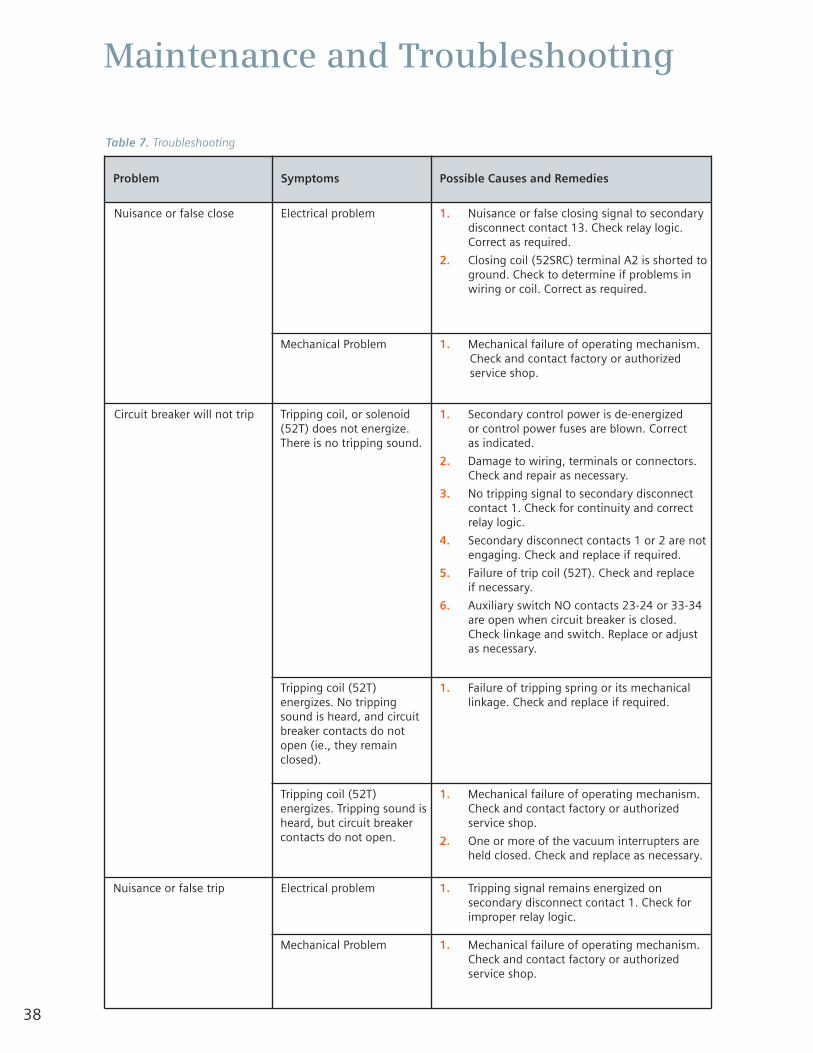
38
Maintenance and Troubleshooting
Problem Symptoms Possible Causes and Remedies
Nuisance or false close Electrical problem 1. Nuisance or false closing signal to secondarydisconnect contact 13. Check relay logic.Correct as required.
2. Closing coil (52SRC) terminal A2 is shorted toground. Check to determine if problems inwiring or coil. Correct as required.
Mechanical Problem 1. Mechanical failure of operating mechanism.Check and contact factory or authorizedservice shop.
Circuit breaker will not trip Tripping coil, or solenoid(52T) does not energize.There is no tripping sound.
1. Secondary control power is de-energized or control power fuses are blown. Correct as indicated.
2. Damage to wiring, terminals or connectors.Check and repair as necessary.
3. No tripping signal to secondary disconnectcontact 1. Check for continuity and correctrelay logic.
4. Secondary disconnect contacts 1 or 2 are notengaging. Check and replace if required.
5. Failure of trip coil (52T). Check and replace if necessary.
6. Auxiliary switch NO contacts 23-24 or 33-34are open when circuit breaker is closed.Check linkage and switch. Replace or adjustas necessary.
Tripping coil (52T)energizes. No trippingsound is heard, and circuitbreaker contacts do notopen (ie., they remainclosed).
1. Failure of tripping spring or its mechanicallinkage. Check and replace if required.
Tripping coil (52T)energizes. Tripping sound isheard, but circuit breakercontacts do not open.
1. Mechanical failure of operating mechanism.Check and contact factory or authorizedservice shop.
2. One or more of the vacuum interrupters areheld closed. Check and replace as necessary.
Nuisance or false trip Electrical problem 1. Tripping signal remains energized onsecondary disconnect contact 1. Check forimproper relay logic.
Mechanical Problem 1. Mechanical failure of operating mechanism.Check and contact factory or authorizedservice shop.
Table 7. Troubleshooting

39

www.usa.siemens.com/energy
All statements, technical information and recommendationscontained herein are based on information and tests webelieve to be reliable. The accuracy or completeness hereof isnot guaranteed. Since conditions of use are outside ourcontrol, the user should determine the suitability of theproduct for its intended use and assumes all risk and liabilitywhatsoever in connection herewith.
Siemens Power Transmission & Distribution, Inc. 7000 Siemens RoadWendell, NC 27591phone: 1-800-347-6659
© 2007, Siemens Power Transmission & Distribution, Inc.All rights reserved.E50001-U229-A285-X-US00 (New - 04-2007)Subject to change without notice.