grove gmk˜˚˛˛b - the marr...
TRANSCRIPT
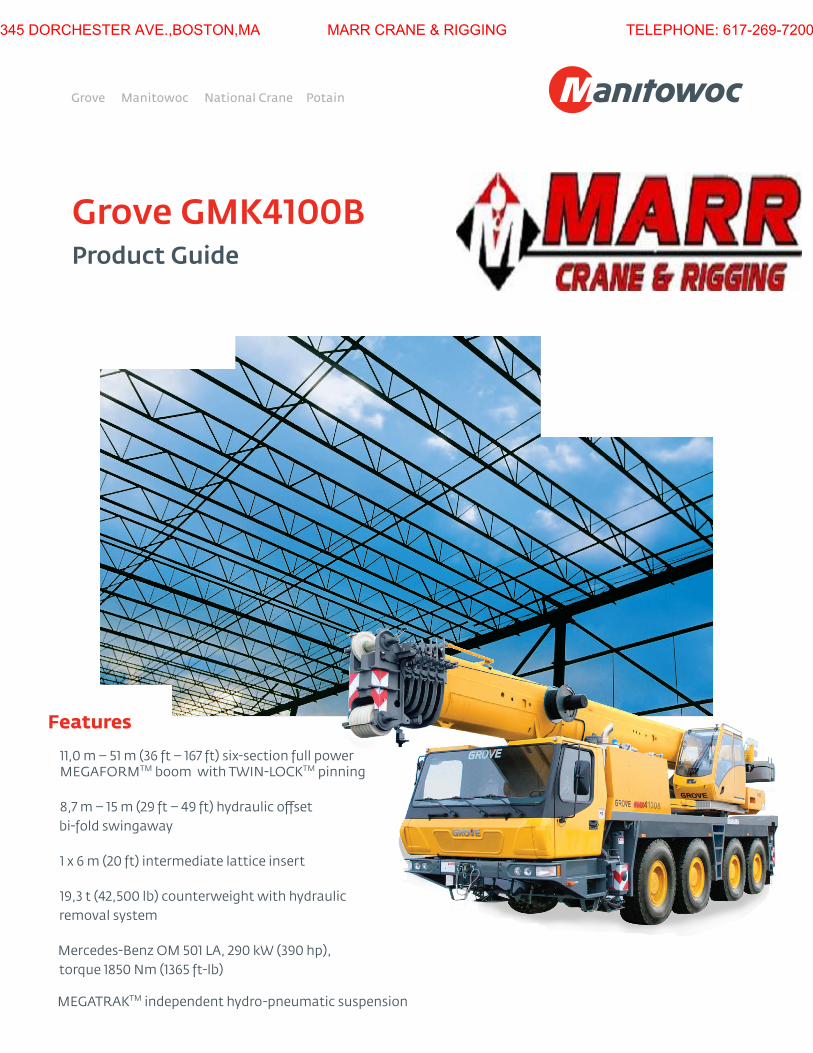
Features
11,0 m – 51 m (36 ft – 167 ft) six-section full power MegaForMTM boom with TWIN-LoCKTM pinning
8,7 m – 15 m (29 ft – 49 ft) hydraulic ofset
bi-fold swingaway
1 x 6 m (20 ft) intermediate lattice insert
19,3 t (42,500 lb) counterweight with hydraulic
removal system
Mercedes-Benz oM 501 La, 290 kW (390 hp),
torque 1850 Nm (1365 ft-lb)
MegaTraKTM independent hydro-pneumatic suspension
Grove GMK4100BProduct Guide
345 DORCHESTER AVE.,BOSTON,MA MARR CRANE & RIGGING TELEPHONE: 617-269-7200

EKS 5 LightMonitoring the lifting condition of the crane at all times EKS works together with, but independently of the ECOS as a complete command and control system or separately as a load moment indicator.
ECOSElectronic Crane Operating System - ECOS enables control of the entire crane's principle operations. Simple programming eases lift planning and a supply of essential information allows full concentration on the lift itself.
TWIN-LOCK™Boom pinning mechanism automatically pins the sections in position using two horizontal pins.
MEGATRAK™he MEGATRAK™ suspension system is the best of road driveline available on the market today. he system’s versatility and performance allows the GMK4100B to operate as a true all-terrain crane. he MEGATRAK™ independent suspension and all-wheel steer system allows wheels to remain on the ground at all times so stresses and weight are not continually transferred between axles. MEGATRAK™ provides true ground clearance where others just raise the chassis.Other beneits of the MEGATRAK™ system are:• A reliable suspension system• Excellent job site maneuverability with all-wheel steering• Commonality among almost all models• A driveline that remains aligned at all times• A steering linkage system that is protected against damage• Constant tire contact for equal tire wear• Reduced maintenance
Features
345 DORCHESTER AVE.,BOSTON,MA MARR CRANE & RIGGING TELEPHONE: 617-269-7200

Speciications 4
Dimensions 7
Weights 8
Counterweight 9
Working range (Main boom) 10
Load charts (Main boom) 11
Working range (Swingaway and extension) 13
Load charts (Swingaway and extension) 14
Working range (Heavy duty jib) 16
Load charts (Heavy duty jib) 17
Symbols glossary 18
Contents
345 DORCHESTER AVE.,BOSTON,MA MARR CRANE & RIGGING TELEPHONE: 617-269-7200

4 *Denotes optional equipment
Cab
All aluminum constructed cab with acoustical lining, hydraulic tilted to 20°. Includes tinted safety glass, adjustable operator’s seat, opening windows at side and rear, hinged windshield with wiper, sun visor and window shade. Other features include diesel heater/defroster, armrest integrated crane controls, drive/steer controls and ergonomically arranged instrumentation.
Control system
Full electronic control of crane functions using control levers with automatic reset to zero. Integrated with the LMI and engine management systems by CAN-BUS. ECOS system with graphic display.
Swing
Two axial piston planetary gear boxes with fixed displacement motors. Infinitely variable to 1.8 rpm. Free swing with holding (rocker switch) and service (foot pedal) brake.
Counterweight
19,3 t (42,500 lb) consisting of various sections with hydraulic installation/removal system controlled from the superstructure cab.
Hydraulic system
2 separate circuits, 1 axial piston variable displacement pump (load sensing) with electronic power limiting control and 1 gear pump for swing. Thermostatically controlled oil coolers keep oil at optimum operating temperature.Tank capacity: 680 L (180 gal).
Hoist
Main and auxiliary hoist are powered by axial piston motor with planetary gear and brake. “Thumb-thumper” hoist drum rotation indicator alerts operator of hoist movement.
Main Auxiliary
Line length: 220 m 220 m (720 ft) (720 ft)
Rope diameter: 16 mm 16 mm
Line speed: 125 m/min 125 m/min (410 fpm) (410 fpm)
Line pull: 50 kN 50 kN (11,240 lb) (11,240 lb)
Superstructure
Boom
11,0 m – 51 m (36 ft – 167 ft) six section, full power MEGAFORMTM boom with TwIN-LOCKTM pinning. Maximum tip height: 54 m (177 ft).
Boom nose
Six nylatron sheaves, mounted on heavy-duty tapered roller bearings with removable pin-type rope guards. Quick reeve boom nose. Removable auxiliary boom nose with removable pin type rope guard.
Boom elevation
Single lift cylinder with safety valve provides boom angle from -3° to +82°.
Hydraulic ofsettable lattice extension
8,7 m – 15 m (29 ft – 49 ft) bi-fold lattice swingaway extension, hydraulically offsettable and luffing under load from 0° - 40°. Maximum tip height: 69 m (226 ft).
*Ofsettable lattice extension
8,7 m – 15 m (29 ft – 49 ft) bi-fold lattice swingaway extension, manually offsettable at 0˚, 20˚ and 40˚.Maximum tip height: 69 m (226 ft).
*Lattice extensions
(1) 6 m (20 ft) insert for use with lattice swingaway extension to increase length to 21 m (69 ft). Maximum tip height: 75 m (246 ft).
Load moment and anti-two block system
Load moment and anti-two block system with audio/visual warning and control lever lockout provides electronic display of boom angle, length, radius, tip height, relative load moment, maximum permissible load, load indication and warning of impending two-block condition.
Specifications
345 DORCHESTER AVE.,BOSTON,MA MARR CRANE & RIGGING TELEPHONE: 617-269-7200

5grove gMK4100B *Denotes optional equipment
Superstructure, continued
*Optional equipment
work lights, mounted on boom base section
Boom mounted aircraft warning light
Radio/CD player for superstructure cab
Air-conditioning
Hook blocks/headache ball
Additional strobe light
Data logger
EKS 5 with graphic display in lieu of EKS 5 Light
Turntable mounted toolbox
360° positive swing lock (NYC requirement)working range limiter
Carrier
Chassis
Box-type, torsion resistant frame is fabricated from high-strength steel.
Outrigger system
Four hydraulic single-stage outrigger beams with vertical cylinders and outrigger pads 500 mm (19.7 in) square. Outriggers can be set in four positions:Full 7 m (23 ft)
Partial 6 m (19.7 ft)
Partial 5 m (16.4 ft)
Retracted 2,3 m (7.6 ft)
Independent horizontal and vertical movement controlled from each side of carrier and the superstructure cab. Electronic crane level indicators.
Engine
Mercedes-Benz OM 501 LA, 6 cylinder, water cooled, turbo-charged, with 290 kw (390 bhp) @ 1800 rpm.
Max. Torque 1850 Nm (1365 ft-lb) @ 1080 rpm. Compression and exhaust brakes.
Engine emissions: EUROMOT/EPA/CARB (off road)
Fuel tank capacity
400 L (106 gal).
Transmission
ZF, AS Tronic, 12 speeds forward, 2 reverse. 2 speed transfer case.
Drive/steer
8 x 6 x 8
Axles
1st axle line - drive/steer
2nd axle line - steer (optional drive)
3rd axle line - drive/steer (connects for all-wheel steer)
4th axle line - drive/steer
Drive axles with planetary hub reduction and center mounted gearing. Inter-axle and cross axle differential locks.
Suspension
Grove’s exclusive MEGATRAK™ suspension. Independent hydro-pneumatic system acting on all wheels with hydraulic lockout. Suspension can be raised 170 mm (6.7 in) or lowered 130 mm (5.1 in) both longitudinally and transversely. Features an automatic leveling system for highway travel.
Tires
8 tires, 16.00R25 (Vehicle width – 2,75 m [9.0 ft])
Steering
Dual circuit, hydraulic power assisted steering system. Transfer case mounted, ground driven emergency steering pump. Axles 1, 2, and 4 steer on highway. Separate steering of the 3rd and 4th axles for all wheel steer and crab-steering, controlled by an electronic rocker switch.
Brakes
Service brakes: pneumatic dual circuit acting on all wheels. Standard anti-lock brake system (ABS).
Parking brake: pneumatically operated spring loaded brake acting on axle lines 2 and 4.
Air dryer.
Specifications
345 DORCHESTER AVE.,BOSTON,MA MARR CRANE & RIGGING TELEPHONE: 617-269-7200
6 *Denotes optional equipment
Carrier, continued
Cab
Two-man, aluminum construction includes the following features: safety glass; driver seat with pneumatic suspension, passenger seat, engine-dependent hot water heater, complete instrumentation and driving controls.
Electrical system
24 V system with three-phase alternator 28 V/100A,
2 batteries 12 V/170 Ah.
Maximum speed
85 km/h (53 mph).
Gradeability (theoretical)
70% with 14.00 tires.
63% with 16.00/20.5 tires.
Miscellaneous standard equipment
work lights; tool kit; fire extinguishers; auxiliary boom nose; radio/CD player in carrier cab, heated rear view mirrors, wind speed indicator.
*Optional equipment
Stainless steel exhaust system with spark arrestor
Air-conditioning - combined system
14.00R25 tires (vehicle width 2,55 m [8.4 ft])
20.5R25 tires (vehicle width 2,88 m [9.5 ft])
8x8x8 drive/steer
Electric driveline retarder
Engine-independent diesel cab heater, with engine pre-heater
Timer for diesel heater
Strobe light
Spare tire and wheel with carry bracket
Rear mounted stowage box
Outrigger pad load indicator
Tool box
Engine shut down valve
Tiltable carrier cab
Specifications
345 DORCHESTER AVE.,BOSTON,MA MARR CRANE & RIGGING TELEPHONE: 617-269-7200

7grove gMK4100B
*
Ra ���� mm
� ��.�'�
Ra �� ��� mm
���.�'�
Ra ���� mm ���.�'�
Ra
����
mm
���.
�'�
Ra
����
mm
���.�
'�
����
mm
��.�
'�
����
mm
���.
�'�
����
mm
���.
�'�
����
mm
���.
�'�
���� mm ��.�'�
���� mm ���.�'�
���� mm ���.�'� ���� mm ��.�'�
R ���� mm ���.�'�
R �� ��� mm
� ��.�'�
R �� ��� mm
���.�'�
R ���� mm ���.�'�
R �
���
mm
���.
�'�
R �
���
mm
���.
�'�
*��.�� tires � ���� mm ��.�'� ��.�� tires � ���� mm ��.�'� ��.� tires � ���� mm ��.�'�
�� ��� mm���.�'�
���� mm ���.�'���°
��� mm��.� ft�
���� mm��.�'�
���� mm��.�'�
��°
���� mm��.�'�
���� mm��.�'�
���� mm��.�'�
�� ��� mm ���.�'�
�� ��� mm ���.�'�
���� mm��.� ft�
���� mm��.�'�
��� mm��.�'�
*��.�� tires � ���� mm ���.�'� ��.��/��.� � ���� mm ���.�'�
���� mm ���.�'�
�*�
�� ��� mm���.�'� ���.�' with auxiliary hoist�
Dimensions
345 DORCHESTER AVE.,BOSTON,MA MARR CRANE & RIGGING TELEPHONE: 617-269-7200
8THIS CHART IS ONLY A GUIDE AND SHOULD NOT BE USED TO OPERATE THE CRANE.
The individual crane’s load chart, operating instructions and other instructional plates must be read and understood prior to operating the crane.
�� ��� mm���'�
���� mm ���.�'�
���� mm��.�'�
���� mm��.�'�
���� mm��.�'�
���� mm��.�'�
���� mm��.�'�
���� mm���.�'�
���� mm��.�'�
Weights
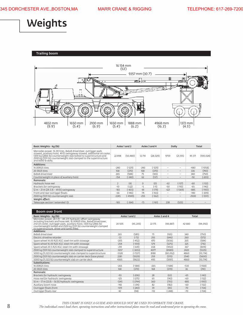
Trailing boom
Basic Weights - kg (lb) Axles 1 and 2 Axles 3 and 4 TotalMercedes power, 28.5 ft – 49.2 ft hydraulic ofset swingaway including brackets and hose reel, 16.00r25 tires, 8x6x8 drive/steer, 2nd oil cooler, outrigger pads, auxiliary hoist, 1300 kg (2866 lb) counterweight bolted and 2500 kg (5511 lb) counterweight clamped to superstructure, driver and tanks illed.
20 505 (45,205) 22 175 (48,887) 42 680 (94,092)
Additions:8x8x8 drive/steer 265 (585) 75 (165) 340 (750)electric driveline retarder -33 (-73) 293 (646) 260 (573)Spare wheel 14.00 r25 XgC steel rim with stowage -205 (-452) 470 (1036) 265 (584)Spare wheel 16.00 r25 XgC steel rim with stowage -254 (-559) 579 (1275) 325 (716)Spare wheel 20.5 r25 XgC steel rim with stowage -291 (-641) 658 (1450) 367 (809)2500 kg (5511 lb) counterweight slab clamped to superstructure -1657 (-3653) 4077 (8989) 2420 (5335)5000 kg (11,023 lb) counterweight slab clamped to superstructure -3328 (-7337) 8188 (80,052) 4860 (10,714)2500 kg (5511 lb) counterweight slab on carrier deck (base plate) 2281 (5029) 259 (570) 2540 (5600)5000 kg (11,023 lb) counterweight slab on carrier deck 4365 (9623) 495 (1091) 4860 (10,714)Substitutions:14.00r25 tires -265 (-584) -265 (-584) -530 (-1168)20.5r25 tires 168 (370) 168 (370) 36 (741)Removals:Brackets for hydraulic swingaway -93 (-206) 28 (63) -65 (-143)Hose reel for hydraulic swingaway -125 (-275) 65 (143) -60 (-132)10 m – 17 m (33 ft – 56 ft) hydraulic swingaway -1245 (-2744) 360 (793) -885 (-1951)auxiliary boom nose -142 (-314) 82 (182) -60 (-132)outrigger loats front -109 (-240) 39 (85) -70 (-154)outrigger loats rear 42 (94) -112 (-248) -70 (-154)
Boom over front
Basic Weights - kg (lb) Axles 1 and 2 Axles 3 and 4 Dolly Total
Mercedes power, 16.00 tires, 8x6x8 drive/steer, outrigger pads stowed, auxiliary hoist, 49 ft swingaway stowed, additional oil cooler, 1300 kg (2866 lb) counterweight slab bolted to superstructure and 2500 kg (5511 lb) counterweight slab clamped to the superstructure and 6000 lb dolly.
22 898 (50,480) 12 714 (28,029) 9759 (21,515) 45 371 (100,024)
Additions:14.00r25 tires -240 (-529) -240 (-529) – – -480 (-1058)20.5r25 tires 168 (370) 168 (370) – – 336 (740)8x8x8 drive/steer 265 (584) 75 (165) – – 340 (750)Counterweight in place of auxiliary hoist -154 (-340) 62 (137) – – -92 (-203)Removals:Hydraulic hose reel 2 (4) 0 (0) -62 (-137) -60 (-132)Brackets for swingaway -10 (-22) -5 (-11) -50 (-110) -65 (-143)12 m – 21 m (29.5 ft – 49 ft) swingaway -183 (-403) -81 (-179) -621 (-1369) -885 (-1951)Front and rear outrigger loats -66 (-146) -74 (-163) – – -140 (-309)2500 kg (5511 lb) counterweight slab -2245 (-4949) -255 (-562) – – -2500 (-5511)Weight efect:Telescope section 1 extended 1 ft -165 (-364) -73 (-161) 238 (525) – –
345 DORCHESTER AVE.,BOSTON,MA MARR CRANE & RIGGING TELEPHONE: 617-269-7200

9grove gMK4100B
������ �����
���� mm ���.�'�
���� mm ��.�'�
���� mm��.�'�
� � � � �x xx x xx x x xx x x xx x x x xx x 2x x
x x x 2x x
x x 2x 2x x
Counterweight configurations kg �lb�
1800 (3900)
4300 (9400)
6800 (14,900)
9300 (20,500)
11 800 (26,000)
16 800 (37,000)
19 300 (42,500)
14 300 (31,500)
��� kg����� lb�
���� mm ��.�'�
���� kg����� lb�
���� kg����� lb�
���� kg���,��� lb�
���� kg ����� lb�
�
�
�
�
�
Counterweight
345 DORCHESTER AVE.,BOSTON,MA MARR CRANE & RIGGING TELEPHONE: 617-269-7200

10
��� ��� ��� �� �� �� �� �� �
��
�
��
��
��
���
���
���
���
���
��o
��.�'
��.�'
��.�'
��.�'
���.�'
���.�'
���.�'
���.�'
��.�'
���.�'
���.�'
Hei
ght
from
the
gro
und
in fe
et
Operating radius in feet from axis of rotation R �ft�
Tip heights shown in the working range diagram do not consider loaded boom deflection.
Hook block H
���� mm ���.� ft�
���� mm ��.� ft�
���� mm ��.� ft�
���� mm ��.� ft�
���� mm ��.� ft�
�� USt, � sheave quick�reeving
�� USt, � sheave quick�reeving
�� USt, � sheave quick�reeving
�� USt, � sheave quick�reeving
� USt, � single headache ball
Working range
36 ft – 167 ft main boom
345 DORCHESTER AVE.,BOSTON,MA MARR CRANE & RIGGING TELEPHONE: 617-269-7200

11grove gMK4100BTHIS CHART IS ONLY A GUIDE AND SHOULD NOT BE USED TO OPERATE THE CRANE.
The individual crane’s load chart, operating instructions and other instructional plates must be read and understood prior to operating the crane
Pounds x 1000Boom Extension
Load chartsMain boom
11,0 m – 51 m 19 300 kg 26.6 ft x 23.0 ft 360˚ (36 ft – 167 ft) (42,500 lb) (100%)
11,0 m – 51 m 16 800 kg 26.6 ft x 23.0 ft 360˚ (36 ft – 167 ft) (37,000 lb) (100%)
Feet 36.1 49.7 63.2 76.4 89.3 101.7 115.3 128.8 142.1 154.9 167.3
8 * 200.010 154.0 132.0 123.0 109.015 114.0 109.0 102.0 95.0 80.020 92.0 90.0 87.0 81.0 76.0 61.0 45.025 71.0 73.0 73.0 67.0 66.0 58.0 45.0 33.830 59.0 56.0 56.0 52.0 51.0 41.8 33.8 25.4 19.635 47.0 48.0 45.0 45.0 42.2 37.8 33.0 25.4 19.6 15.840 38.8 38.0 38.0 35.6 33.4 30.4 25.4 19.6 15.845 32.4 32.6 32.6 30.4 28.6 27.6 25.4 19.6 15.850 27.4 28.8 28.4 26.4 25.2 23.8 23.6 19.6 15.855 24.8 24.4 23.0 23.6 20.8 20.6 19.4 15.860 21.6 21.4 20.4 20.8 18.2 18.2 18.2 15.865 19.2 18.8 19.0 18.6 16.6 16.0 16.2 15.670 16.6 17.4 16.6 15.6 14.6 14.4 14.875 14.6 15.6 14.6 14.8 13.6 13.4 13.280 14.0 13.0 13.4 12.8 12.4 11.885 12.4 11.6 12.0 12.0 11.4 10.890 9.4 10.4 10.8 10.8 10.6 9.695 9.2 9.8 9.8 9.6 8.8
100 8.4 9.0 8.8 8.6 7.8105 8.4 8.0 7.8 7.0110 7.8 7.4 7.0 6.4115 4.2 6.8 6.2 5.6120 6.0 5.6 5.0125 3.4 5.0 4.4130 2.8 4.4 3.8135 4.0 3.4140 2.8145 2.4150 2.0
* 0° over rear with special equipment Loads above 130,000 lb require additional equipment
Feet 36.1 49.7 63.2 76.4 89.3 101.7 115.3 128.8 142.1 154.9 167.3
10 154.0 132.0 123.0 109.015 114.0 109.0 102.0 95.0 80.020 92.0 90.0 87.0 81.0 76.0 61.0 45.025 71.0 72.0 68.0 65.0 62.0 58.0 45.0 33.830 57.0 54.0 52.0 51.0 48.0 41.8 33.8 25.4 19.635 44.0 45.0 42.6 42.4 39.6 37.2 33.0 25.4 19.6 15.840 36.4 36.0 35.6 33.2 31.2 30.0 25.4 19.6 15.845 30.2 31.6 30.6 28.4 27.0 25.6 25.2 19.6 15.850 25.6 26.8 26.4 24.4 25.0 22.0 21.8 19.6 15.855 23.2 22.8 21.4 21.8 19.2 19.0 19.2 15.860 20.2 19.8 20.2 19.4 17.6 16.6 16.8 15.865 17.8 17.4 18.2 17.2 16.6 15.6 15.4 15.270 15.2 16.2 15.2 15.4 14.6 14.4 13.475 13.4 14.4 13.4 13.8 13.6 13.0 12.080 12.8 12.0 12.4 12.2 11.8 10.885 11.4 10.6 11.0 11.0 10.6 9.690 8.6 9.4 10.2 10.0 9.6 8.695 8.4 9.4 9.0 8.6 7.8
100 7.4 8.6 8.2 7.8 7.0105 7.8 7.4 7.0 6.2110 7.2 6.6 6.2 5.6115 3.4 6.0 5.6 4.8120 5.4 4.8 4.2125 2.6 4.4 3.6130 2.2 3.8 3.2135 3.4 2.6140 2.2145 1.8
Loads above 130,000 lb require additional equipment
Pounds x 1000Boom Extension
345 DORCHESTER AVE.,BOSTON,MA MARR CRANE & RIGGING TELEPHONE: 617-269-7200

12THIS CHART IS ONLY A GUIDE AND SHOULD NOT BE USED TO OPERATE THE CRANE.
The individual crane’s load chart, operating instructions and other instructional plates must be read and understood prior to operating the crane.
Load chartsMain boom
11,0 m – 51 m 9300 kg 26.6 ft x 23.0 ft 360˚ (36 ft – 167 ft) (20,500 lb) (100%)
11,0 m – 51 m 1800 kg 26.6 ft x 23.0 ft 360˚ (36 ft – 167 ft) (3900 lb) (100%)
Pounds x 1000
Pounds x 1000
Boom Extension
Boom Extension
Feet 36.1 49.7 63.2 76.4 89.3 101.7 115.3 128.8 142.1 154.9 167.3
10 154.0 132.0 123.0 109.015 114.0 109.0 102.0 95.0 80.020 85.0 80.0 74.0 67.0 65.0 61.0 45.025 60.0 58.0 56.0 53.0 52.0 48.0 44.0 33.830 45.0 43.6 43.2 40.8 37.6 35.0 33.4 25.4 19.635 34.6 36.6 35.2 33.2 30.8 30.8 27.4 25.4 19.6 15.840 29.6 29.4 27.6 27.2 25.8 23.6 22.4 19.6 15.845 24.4 24.8 23.4 23.8 22.0 21.8 20.4 19.0 15.850 20.6 20.8 20.2 20.6 19.0 18.8 18.6 17.6 15.855 17.8 17.4 18.0 16.4 16.8 16.4 15.4 14.260 15.8 14.8 15.8 14.4 15.2 14.4 13.4 12.465 14.0 12.8 13.6 13.2 13.6 12.8 11.8 10.870 11.0 12.0 12.2 12.0 11.2 10.4 9.475 9.6 10.4 11.0 10.8 10.0 9.2 8.280 9.6 9.8 9.6 9.0 8.2 7.285 8.8 8.6 8.4 8.0 7.2 6.290 5.2 7.6 7.4 7.0 6.4 5.495 6.8 6.6 6.2 5.6 4.6
100 4.6 5.8 5.4 4.8 4.0105 5.2 4.6 4.2 3.4110 4.4 4.0 3.6 2.8115 3.4 3.0 2.2120 3.0 2.4 1.8125 2.0
Loads above 130,000 lb require additional equipment
Feet 36.1 49.7 63.2 76.4 89.3 101.7 115.3 128.8 142.1 154.9 167.3
10 154.0 132.0 123.0 109.015 108.0 98.0 87.0 77.0 72.020 65.0 60.0 58.0 56.0 52.0 47.0 43.425 44.0 44.0 44.0 41.8 38.8 35.4 32.6 30.830 34.0 33.8 32.2 30.2 30.2 27.6 27.0 23.4 19.635 25.8 27.0 26.0 24.2 24.4 22.6 23.0 21.2 18.4 15.840 21.6 21.8 19.6 20.0 20.0 19.0 17.8 16.4 15.045 17.4 18.6 16.0 17.0 16.8 15.8 14.8 13.6 12.450 14.2 15.4 13.8 15.0 14.2 13.4 12.4 11.4 10.255 12.8 12.4 12.8 12.0 11.4 10.6 9.6 8.460 10.6 11.0 11.0 10.4 9.8 9.0 8.0 7.065 9.0 9.2 9.6 9.0 8.4 7.6 6.8 5.870 7.8 8.0 7.8 7.2 6.4 5.6 4.675 6.6 6.8 6.6 6.2 5.4 4.8 3.880 5.8 5.6 5.2 4.6 3.8 3.085 5.0 4.8 4.6 3.8 3.2 2.290 4.0 3.8 3.2 2.695 3.4 3.0 2.6 2.0
100 2.6 2.0105 2.0
Loads above 130,000 lb require additional equipment
345 DORCHESTER AVE.,BOSTON,MA MARR CRANE & RIGGING TELEPHONE: 617-269-7200

13grove gMK4100B
��� ��� ��� ��� ��� �� �� �� �� �
��
�
��
��
��
���
���
���
���
���
���
���
���
��°
���.�'
+��.�'+��.�'
+��.�'�°
��°
��°
Operating radius in feet from axis of rotation R �ft�
Hei
ght
from
the
gro
und
in fe
et
Working range
167.3 ft main boom with hydraulic luffing 28.5 ft and 49.2 ft swingaway and 1 x 19.7 ft insert
Tip heights shown in the working range diagram do not consider loaded boom deflection.
345 DORCHESTER AVE.,BOSTON,MA MARR CRANE & RIGGING TELEPHONE: 617-269-7200
14THIS CHART IS ONLY A GUIDE AND SHOULD NOT BE USED TO OPERATE THE CRANE.
The individual crane’s load chart, operating instructions and other instructional plates must be read and understood prior to operating the crane.
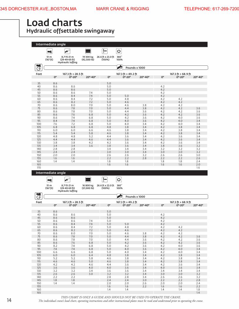
Load chartsHydraulic offsettable swingaway
51 m 8,7-15-21 m 19 300 kg 26.6 ft x 23.0 ft 360˚ (167 ft) (29-49-69 ft) (42,500 lb) (100%) 100% Hydraulic luffing
51 m 8,7-15-21 m 16 800 kg 26.6 ft x 23.0 ft 360˚ (167 ft) (29-49-69 ft) (37,000 lb) (100%) 100% Hydraulic luffing
Pounds x 1000
Pounds x 1000
Boom Extension
Boom Extension
Feet 167.3 ft + 28.5 ft 167.3 ft + 49.2 ft 167.3 ft + 68.9 ft0° 0°-20° 20°-40° 0° 0°-20° 20°-40° 0° 0°-20° 20°-40°
35 8.6 5.040 8.6 8.6 5.0 4.245 8.6 8.6 5.0 4.250 8.6 8.6 7.4 5.0 4.255 8.6 8.4 7.4 5.0 5.0 4.260 8.6 8.4 7.2 5.0 4.8 4.2 4.265 8.6 8.2 7.2 5.0 4.6 4.2 4.270 8.6 8.0 7.0 5.0 4.6 3.8 4.2 4.275 8.6 7.8 7.0 5.0 4.4 3.8 4.2 4.2 3.680 8.6 7.8 7.0 5.0 4.4 3.6 4.2 4.2 3.685 8.6 7.6 6.8 5.0 4.2 3.6 4.2 4.2 3.690 8.6 7.4 6.8 5.0 4.2 3.6 4.2 4.0 3.695 8.4 7.4 6.8 5.0 4.0 3.6 4.2 4.0 3.4
100 7.6 7.2 6.8 5.0 4.0 3.4 4.2 4.0 3.4105 6.8 6.8 6.8 4.8 3.8 3.4 4.2 3.8 3.4110 6.0 6.0 6.6 4.6 3.8 3.4 4.2 3.8 3.4115 5.4 5.4 5.8 4.6 3.8 3.4 4.2 3.8 3.4120 4.8 4.8 5.2 4.4 3.6 3.4 4.2 3.6 3.4125 4.4 4.4 4.6 4.4 3.6 3.4 4.2 3.6 3.4130 3.8 3.8 4.2 4.2 3.6 3.4 4.2 3.6 3.4135 3.4 3.4 3.6 3.8 3.6 3.4 3.8 3.6 3.2140 2.8 2.8 3.4 3.4 3.4 3.2 3.2 3.2145 2.4 2.4 3.0 3.0 3.4 3.0 3.0 3.2150 2.0 2.0 2.6 2.6 3.2 2.6 2.6 3.0155 1.6 1.6 2.2 2.2 2.8 2.2 2.2 2.6160 1.4 1.4 1.8 1.8 1.8 1.8 2.4165 1.6 1.6 1.6 1.6 2.0170 1.6
Feet 167.3 ft + 28.5 ft 167.3 ft + 49.2 ft 167.3 ft + 68.9 ft0° 0°-20° 20°-40° 0° 0°-20° 20°-40° 0° 0°-20° 20°-40°
35 8.6 5.040 8.6 8.6 5.0 4.245 8.6 8.6 5.0 4.250 8.6 8.6 7.4 5.0 4.255 8.6 8.4 7.4 5.0 5.0 4.260 8.6 8.4 7.2 5.0 4.8 4.2 4.265 8.6 8.2 7.2 5.0 4.6 4.2 4.270 8.6 8.0 7.0 5.0 4.6 3.8 4.2 4.275 8.6 7.8 7.0 5.0 4.4 3.8 4.2 4.2 3.680 8.6 7.8 7.0 5.0 4.4 3.6 4.2 4.2 3.685 8.6 7.6 6.8 5.0 4.2 3.6 4.2 4.2 3.690 8.2 7.4 6.8 5.0 4.2 3.6 4.2 4.0 3.695 7.4 7.4 6.8 5.0 4.0 3.6 4.2 4.0 3.4
100 6.6 6.6 6.8 5.0 4.0 3.4 4.2 4.0 3.4105 6.0 6.0 6.4 4.8 3.8 3.4 4.2 3.8 3.4110 5.2 5.2 5.8 4.6 3.8 3.4 4.2 3.8 3.4115 4.6 4.6 5.0 4.6 3.8 3.4 4.2 3.8 3.4120 4.2 4.2 4.6 4.4 3.6 3.4 4.2 3.6 3.4125 3.6 3.6 4.0 4.0 3.6 3.4 4.0 3.6 3.4130 3.2 3.2 3.4 3.6 3.6 3.4 3.4 3.4 3.4135 2.6 2.6 3.0 3.2 3.2 3.4 3.0 3.0 3.2140 2.2 2.2 2.8 2.8 3.4 2.6 2.6 3.2145 1.8 1.8 2.4 2.4 3.0 2.2 2.2 2.8150 1.4 1.4 2.0 2.0 2.6 2.0 2.0 2.4155 1.6 1.6 2.2 1.6 1.6 2.2160 1.4 1.4 1.4 1.4 1.8165 1.4
Intermediate angle
Intermediate angle
345 DORCHESTER AVE.,BOSTON,MA MARR CRANE & RIGGING TELEPHONE: 617-269-7200

15grove gMK4100BTHIS CHART IS ONLY A GUIDE AND SHOULD NOT BE USED TO OPERATE THE CRANE.
The individual crane’s load chart, operating instructions and other instructional plates must be read and understood prior to operating the crane
Load chartsManual offsettable swingaway
51 m 8,7-15-21 m 19 300 kg 26.6 ft x 23.0 ft 360˚ (167 ft) (29-49-69 ft) (42,500 lb) (100%) 100%
51 m 8,7-15-21 m 16 800 kg 26.6 ft x 23.0 ft 360˚ (167 ft) (29-49-69 ft) (37,000 lb) (100%) 100%
Pounds x 1000
Pounds x 1000
Boom Extension
Boom Extension
Feet 167.3 ft + 28.5 ft 167.3 ft + 49.2 ft 167.3 ft + 68.9 ft0° 20° 40° 0° 20° 40° 0° 20° 40°
35 8.6 5.040 8.6 8.6 5.0 4.245 8.6 8.6 5.0 4.250 8.6 8.6 7.4 5.0 4.255 8.6 8.4 7.4 5.0 5.0 4.260 8.6 8.4 7.2 5.0 4.8 4.2 4.265 8.6 8.2 7.2 5.0 4.6 4.2 4.270 8.6 8.0 7.0 5.0 4.6 3.8 4.2 4.275 8.6 7.8 7.0 5.0 4.4 3.8 4.2 4.2 3.680 8.6 7.8 7.0 5.0 4.4 3.6 4.2 4.2 3.685 8.6 7.6 6.8 5.0 4.2 3.6 4.2 4.2 3.690 8.6 7.4 6.8 5.0 4.2 3.6 4.2 4.0 3.695 8.4 7.4 6.8 5.0 4.0 3.6 4.2 4.0 3.4
100 7.6 7.2 6.8 5.0 4.0 3.4 4.2 4.0 3.4105 6.8 7.2 6.8 4.8 3.8 3.4 4.2 3.8 3.4110 6.0 6.6 6.8 4.6 3.8 3.4 4.2 3.8 3.4115 5.4 5.8 6.2 4.6 3.8 3.4 4.2 3.8 3.4120 4.8 5.2 5.4 4.4 3.6 3.4 4.2 3.6 3.4125 4.4 4.6 4.8 4.4 3.6 3.4 4.2 3.6 3.4130 3.8 4.2 4.4 4.2 3.6 3.4 4.2 3.6 3.4135 3.4 3.6 3.8 3.8 3.6 3.4 3.8 3.6 3.2140 2.8 3.2 3.4 3.4 3.4 3.2 3.4 3.2145 2.4 2.6 3.0 3.4 3.4 3.0 3.4 3.2150 2.0 2.2 2.6 3.2 3.4 2.6 3.0 3.2155 1.6 1.8 2.2 2.8 3.0 2.2 2.6 3.0160 1.4 1.4 1.8 2.4 1.8 2.4 2.6165 1.6 2.0 1.6 2.0 2.2170 1.6 1.6 1.8175 1.4
Feet 167.3 ft + 28.5 ft 167.3 ft + 49.2 ft 167.3 ft + 68.9 ft0° 20° 40° 0° 20° 40° 0° 20° 40°
35 8.6 5.040 8.6 8.6 5.0 4.245 8.6 8.6 5.0 4.250 8.6 8.6 7.4 5.0 4.255 8.6 8.4 7.4 5.0 5.0 4.260 8.6 8.4 7.2 5.0 4.8 4.2 4.265 8.6 8.2 7.2 5.0 4.6 4.2 4.270 8.6 8.0 7.0 5.0 4.6 3.8 4.2 4.275 8.6 7.8 7.0 5.0 4.4 3.8 4.2 4.2 3.680 8.6 7.8 7.0 5.0 4.4 3.6 4.2 4.2 3.685 8.6 7.6 6.8 5.0 4.2 3.6 4.2 4.2 3.690 8.2 7.4 6.8 5.0 4.2 3.6 4.2 4.0 3.695 7.4 7.4 6.8 5.0 4.0 3.6 4.2 4.0 3.4
100 6.6 7.2 6.8 5.0 4.0 3.4 4.2 4.0 3.4105 6.0 6.4 6.8 4.8 3.8 3.4 4.2 3.8 3.4110 5.2 5.8 6.0 4.6 3.8 3.4 4.2 3.8 3.4115 4.6 5.0 5.4 4.6 3.8 3.4 4.2 3.8 3.4120 4.2 4.6 4.8 4.4 3.6 3.4 4.2 3.6 3.4125 3.6 4.0 4.2 4.0 3.6 3.4 4.0 3.6 3.4130 3.2 3.4 3.6 3.6 3.6 3.4 3.4 3.6 3.4135 2.6 3.0 3.2 3.2 3.6 3.4 3.0 3.6 3.2140 2.2 2.6 2.8 3.4 3.4 2.6 3.2 3.2145 1.8 2.0 2.4 3.0 3.2 2.2 2.8 3.2150 1.4 1.6 2.0 2.6 2.8 2.0 2.4 2.8155 1.4 1.6 2.2 2.4 1.6 2.2 2.4160 1.4 1.8 1.4 1.8 2.0165 1.4 1.4 1.8170 1.4
Fixed angle
Fixed angle
345 DORCHESTER AVE.,BOSTON,MA MARR CRANE & RIGGING TELEPHONE: 617-269-7200
16
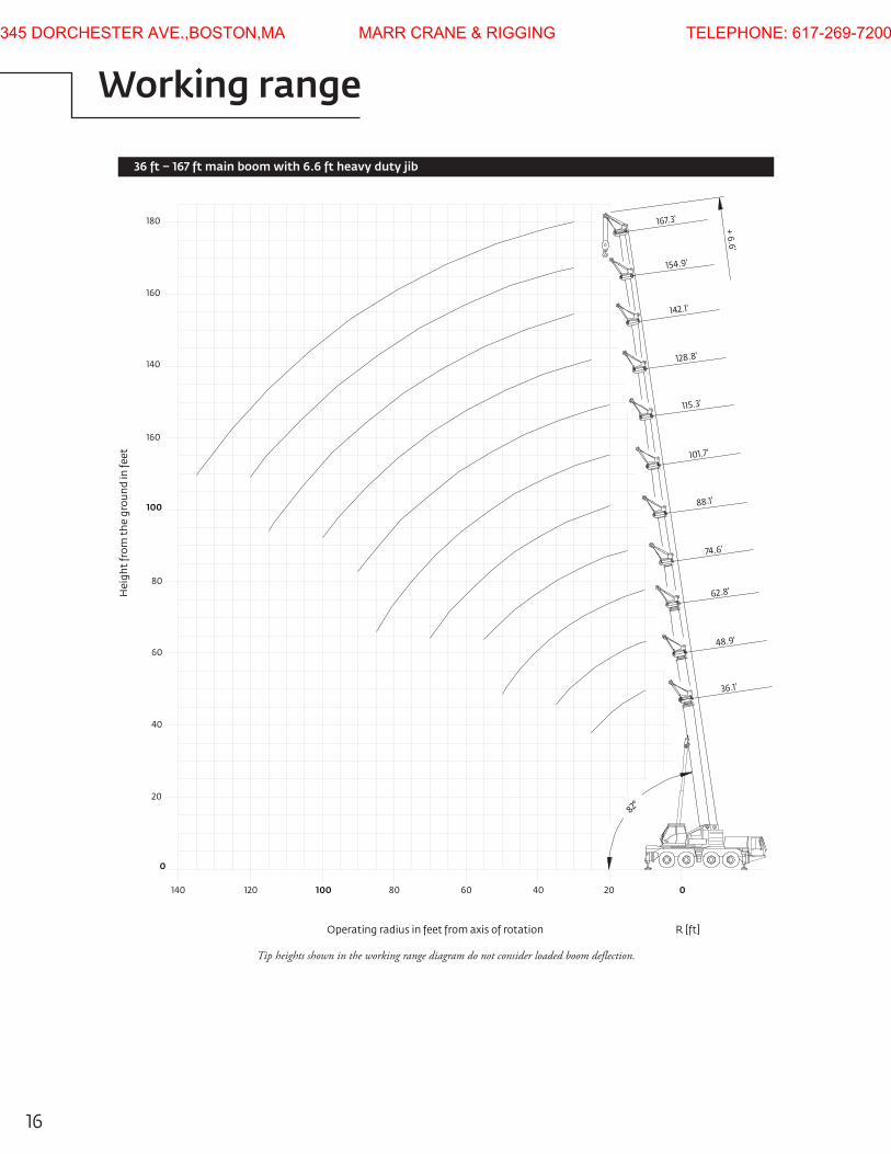
��� ��� �� �� �� �� �
��
�
��
��
��
���
���
���
���
���
���
Hei
ght
from
the
gro
und
in fe
et
Operating radius in feet from axis of rotation R �ft�
��.�'
��.�'
��.�'
��.�'
���.�'
��.�'
���.�'
���.�'
���.�'
���.�'
���.�'
+ �.�'
��°
Working range
36 ft – 167 ft main boom with 6.6 ft heavy duty jib
Tip heights shown in the working range diagram do not consider loaded boom deflection.
345 DORCHESTER AVE.,BOSTON,MA MARR CRANE & RIGGING TELEPHONE: 617-269-7200

17grove gMK4100B
Load chartsHeavy duty jib
11,0 m - 51 m 2 m 19 300 kg 26.6 ft x 23.0 ft 360˚ (36 ft - 167 ft) (6.6 ft) (42,500 lb) (100%) 100%
11,0 m - 51 m 2 m 16 800 kg 26.6 ft x 23.0 ft 360˚ (36 ft - 167 ft) (6.6 ft) (37,000 lb) (100%) 100%
Pounds x 1000
Pounds x 1000
Boom Extension
Boom Extension
Feet 36.1 ft + 6.6 ft 74.6 ft + 6.6 ft 128.8 ft + 6.6 ft 167.3 ft + 6.6 ft0° 40° 0° 40° 0° 40° 0° 40°
10 22.015 22.0 22.0 22.020 22.0 22.0 22.025 22.0 22.0 22.0 22.030 22.0 22.0 22.0 22.0 12.235 22.0 22.0 22.0 12.240 22.0 22.0 22.0 12.245 22.0 22.0 22.0 12.250 22.0 22.0 22.0 12.255 22.0 22.0 20.6 21.0 12.260 22.0 18.0 18.6 12.265 19.4 16.0 16.4 12.270 14.0 14.4 12.275 12.4 12.8 12.8 12.280 11.2 11.4 11.4 11.885 10.4 10.4 10.2 10.690 9.6 9.6 9.2 9.695 8.8 8.8 8.4 8.6
100 8.4 8.4 7.4 7.6105 7.8 6.8 7.0110 7.4 6.0 6.2115 7.0 5.4 5.4120 4.6 4.8125 4.0 4.2130 3.6 3.6135 3.0 3.2140 2.6145 2.2150 1.8155 1.4160
Feet 36.1 ft + 6.6 ft 74.6 ft + 6.6 ft 128.8 ft + 6.6 ft 167.3 ft + 6.6 ft0° 40° 0° 40° 0° 40° 0° 40°
10 22.015 22.0 22.0 22.020 22.0 22.0 22.025 22.0 22.0 22.0 22.030 22.0 22.0 22.0 22.0 12.235 22.0 22.0 22.0 12.240 22.0 22.0 22.0 12.245 22.0 22.0 22.0 12.250 22.0 22.0 22.0 12.255 22.0 22.0 19.0 19.4 12.260 20.4 16.6 17.0 12.265 18.0 14.6 15.0 12.270 12.8 13.2 12.275 12.0 11.8 11.6 12.080 11.2 11.2 10.4 10.685 10.4 10.4 9.2 9.690 9.6 9.6 8.2 8.695 8.8 8.8 7.4 7.6
100 8.4 8.4 6.6 6.8105 7.6 5.8 6.0110 7.0 5.2 5.4115 6.2 4.6 4.8120 4.0 4.2125 3.4 3.6130 2.8 3.0135 2.4 2.6140 2.0145 1.6150
Fixed angle
Fixed angle
345 DORCHESTER AVE.,BOSTON,MA MARR CRANE & RIGGING TELEPHONE: 617-269-7200

18
Symbols glossary
Drive
RotationElectrical system
Suspension
Fuel tank capacity
Tires
Engine
Brakes
Outrigger controls
Axles Outriggers
Transmission
Frame
Steering
Lights
Boom elevation
Cab
Swing
Hydraulic system
Hoist
Boom nose
Radius
Boom extension
Boom length
Grade
Gear
Boom
Counterweight
Speed
Oil
Extension
HookblockH
Heavy duty jib
345 DORCHESTER AVE.,BOSTON,MA MARR CRANE & RIGGING TELEPHONE: 617-269-7200

19grove gMK4100B
Notes
345 DORCHESTER AVE.,BOSTON,MA MARR CRANE & RIGGING TELEPHONE: 617-269-7200
his document is non-contractual. Constant improvement and engineering progress
make it necessary that we reserve the right to make speciication, equipment, and price changes without notice. Illustrations shown may include optional equipment and accessories and may not include all standard equipment.
AmericasBrazilalphaville
MexicoMonterrey
ChileSantiago
Europe, Middle East, Africa
Czech RepublicNetvorice
FranceBaudemontCergyDecines
GermanyLangenfeld
HungaryBudapest
ItalyLainate
NetherlandsBreda
PolandWarsaw
PortugalBaltar
RussiaMoscow
U.A.E.Dubai
U.K.Buckingham
Asia - PaciicAustraliaBrisbaneMelbourneSydney
ChinaBeijingChengduguangzhou
IndiaDelhiHyderabadPuneKoreaSeoul
PhilippinesMakati CitySingapore
FactoriesBrazilalphaville
ChinaTaianZhangjiagang
FranceCharlieuLa ClayetteMoulins
GermanyWilhelmshaven
IndiaPune
ItalyNiella Tanaro
PortugalBaltarFânzeres
SlovakiaSaris
USAManitowoc Port WashingtonShady grove
Regional oices
Manitowoc - Asia Paciic Shanghai, China Tel: +86 21 6457 0066Fax: +86 21 6457 4955
Manitowoc - Europe, Middle East, Africa Ecully, France Tel: +33 (0)4 72 18 20 20 Fax: +33 (0)4 72 18 20 00
Manitowoc - Americas Manitowoc, Wisconsin, USA Tel: +1 920 684 6621 Fax: +1 920 683 6277
Shady Grove, Pennsylvania, USA Tel: +1 717 597 8121 Fax: +1 717 597 4062
©2010 ManitowocPrinted in USaForm No. gMK4100BPart No. 06-005-2M-0810 www.manitowoc.com
Regional headquarters
345 DORCHESTER AVE.,BOSTON,MA MARR CRANE & RIGGING TELEPHONE: 617-269-7200