gtn 625/635/650 software v6.50 pilot’s guide upgrade...
TRANSCRIPT
GTN 625/635/650 SW v6.50 Pilot’s Guide Upgrade Supplement 190-01004-19 Rev. A
GTN 625/635/650 SOFTWARE v6.50 PILOT’S GUIDE UPGRADE SUPPLEMENTThis supplement contains the pages revised in the GTN 625/635/650 Pilot’s Guide, P/N 190-01004-03, Rev N, regarding the new features of software v6.50. Change bars are placed adjacent to the revised information as described in the revision summary table.
This supplement, in combination with the GTN 625/635/650 Pilot’s Guide, P/N 190-01004-03, Rev. M, is equivalent to the GTN 625/635/650 Pilot’s Guide, P/N 190-01004-03, Rev. N.
Current documents are available at flyGarmin.com
Printed copies may be purchased by contacting Garmin Customer Support.
NOTE: Depending on which version of software is installed and how it is configured, the actual features and screen images may differ from what is shown. For more information regarding feature availability for specific software versions refer to the GTN 625/635/650 Pilot’s Guide, P/N 190-01004-03.

GTN 625/635/650 SW v6.50 Pilot’s Guide Upgrade Supplement 190-01004-19 Rev. A
© 2018 Garmin International, Inc. or its subsidiaries
All Rights Reserved
Except as expressly provided herein, no part of this manual may be reproduced, copied, transmitted, disseminated, downloaded or stored in any storage medium, for any purpose without the express written permission of Garmin. Garmin hereby grants permission to download a single copy of this manual and of any revision to this manual onto a hard drive or other electronic storage medium to be viewed for personal use, provided that such electronic or printed copy of this manual or revision must contain the complete text of this copyright notice and provided further that any unauthorized commercial distribution of this manual or any revision hereto is strictly prohibited.
This manual reflects the operation of system software v6.50 or later. Some differences in operation may be observed when comparing the information in this manual to later software versions.
This part shall comply with Garmin Banned and Restricted Substances document, 001-00211-00.
Garmin®, FliteCharts®, and SafeTaxi® are registered trademarks of Garmin International or its subsidiaries. Garmin SVT™, Telligence™, and Smart Airspace™ are trademarks of Garmin International or its subsidiaries. These trademarks may not be used without the express permission of Garmin.
NavData® is a registered trademark of Jeppesen, Inc.
SkyWatch® and StormScope® are registered trademarks of L-3 Communications.
© 2018 SiriusXM® Satellite Radio, Sirius, SXM and all related marks and logos are trademarks of SiriusXM Radio Inc. All other marks and logos are property of their respective owners. All rights reserved.
The Bluetooth® word mark and logos are registered trademarks owned by Bluetooth SIG, Inc. and any use of such marks by Garmin is under license. Other trademarks and trade names are those of their respective owners.
© 2018 SD® and SDHC Logos are trademarks of SD-3C, LLC. All rights reserved.
Iridium® is a registered trademark of Iridium Communications, Inc. All rights reserved.
The term Wi-Fi® is a registered trademark of the Wi-Fi Alliance®.
United States radar data provided by NOAA; European radar data collected and provided by Meteo France.
For information regarding the Aviation Limited Warranty, refer to Garmin’s website.
For aviation product support, visit flyGarmin.com.

GTN 625/635/650 Pilot’s Guide Revision N, Change Summary
Section Page DescriptionSection 4 – Flight Plans
4 4-1Updated menu options in figure 4-1, “Flight Plan Functional Diagram.”
4.1 4-2Updated screen image in figure 4-4, “Remove Single Existing Waypoint.”
4.2.1 4-4Updated screen image in figure 4-8, “Active Flight Plan Wpt Options.”
4.2.1.2 4-6Updated screen image in figure 4-11, “Active Flight Plan Insert Waypoint Before Option.”
4.2.1.4 4-7 Added “Along Track Offsets” section.4.2.1.5 4-9 Revised sequence steps for clarity.
4.3 4-23Updated screen image in figure 4-43, “Flight Plan Menu.”Updated menu options in figure 4-44, “Flight Plan Menu Functional Diagram.”
4.3.2 4-24 Added note regarding removal of ATKs.4.3.3 4-25 Added “En Route Vertical Navigation” section.4.3.4 4-32 Added “Temperature Compensated Altitude” section.4.3.5 4-33 Added note regarding en route vertical navigation availability.
4.3.6 4-35Added Altitude and Flight Path Angle to list of user-selectable data fields.Added information related to VNAV functionality.
4.3.7.2 4-37 Added note regarding the removal of ATKs.Section 5 – Direct-To
5.5 5-6Updated screen image in figure 5-9, “Touch the Map to Create a MAPWPT as the Direct-To Course Destination.”
Section 6 – Procedures
6 6-1Revised note regarding bar-corrected altitude to include en route vertical navigation.
6.2 6-4 Added note regarding advisory climb altitudes.
6.3 6-8Added note about verifying altitudes when using Descent VNAV.
GTN 625/635/650 SW v6.50 Pilot’s Guide Upgrade Supplement 190-01004-19 Rev. A

Section Page Description
6.46-9
Added note about verifying altitudes (including ATC cleared altitudes) when using Descent VNAV.
6-12 Added table 6-2, “Loading and Activating an Approach.”Section 7 – Waypoint Info
7.7 7-15Added note pertaining to user airport feature availability.Added information related to user airports.
7.8
7-18
Updated screen image in figure 7-24, “Waypoint Info - Create User Waypoint.”Updated Create Waypoint key icon.Added step 4. Includes associated key icon.
7-19Updated screen image in figure 7-26, “Waypoint Info - Create User Waypoint Type.”Added step 8. Includes associated key icon.
7.8.2 7-20Updated screen image in figure 7-28, “Waypoint Info - Set Lat/Lon Coordinate Selection.”
7.9 7-23Added information about overwriting existing user waypoints during import.
Section 8 – Map
8.1.2 8-9Added Altitude Constraints menu option to figure 8-10, “Map Setup Functional Diagram.”
8.1.2.18-11
Added Altitude Constraint feature to table 8-2, “Map Setup Map Options.”
8-15 Added “Altitude Constraints” subsection.
8.6 8-42Added User Airport, TOD/BOD, and ATK to table 8-19, “Map Symbols.”
Section 9 – Traffic9.5.2
9-19Updated screen image in figure 9-11, “ADS-B Traffic Menu.”
9.5.2.1 Added “ADS-B Display” subsection.Section 10 – Terrain
10.1 10-1 Added table 10-1, “Terrain Configurations.”10.2 10-2 Added “GPS Altitude for Terrain” section.
GTN 625/635/650 SW v6.50 Pilot’s Guide Upgrade Supplement 190-01004-19 Rev. A

Section Page Description10.5 10-10 Added “Terrain Alerting” section.
Section 11 – Weather11.3 11-32 Updated hyperlink to Connext weather page on Garmin
website.11.3.4 11-36 Revised Connext Weather activation information.
Section 14 – Utilities
1414-1
Updated screen image in figure 14-1, “Utilities Home Page.”Added table 14-1, “Utilities Page Features.” Includes descriptions for VNAV and Logs pages.
14-3Added VNAV and Logs menu options to figure 14-2, “Utilities Functional Diagram.”
14.1 14-4 Added note regarding feature/page exclusivity.Section 15 – System
15 15-2 Added Keyboard to Setup menu options in figure 15-2, “System Function Summary.”
15.4 15-15 Added Keyboard to list of System Setup page functions.Added COM Sidetone Control and Keyboard menu options to figure 15-19, “System Setup Functions.”
15-16 Updated screen image in figure 15-20, “System Setup Page.”15.4.3 15-19 Added information regarding Include User Airports function.
Updated screen image in figure 15-25, “Select Nearest Airport Criteria.”
15-20 Added step 5 to reflect addition of Include User Airports key.15.4.4.3 15-22 Added “COM Sidetone Control” section.15.4.5 15-23 Added “Keyboard Format” section.15.7 15-32 Added unit values for Position Format to table 15-9, “System
Units Setup.”
GTN 625/635/650 SW v6.50 Pilot’s Guide Upgrade Supplement 190-01004-19 Rev. A

Section Page Description15.7.3 15-35 Added list of available position formats.
Added information about regional position formats.Added figure 15-48, “British National Grid Position Format Detail.”
15-36 Added figure 15-49, “Irish National Grid Position FormatDetail.”Added figure 15-50, “Swiss National Grid Position Format Detail.”Updated screen image in figure 15-51, “Position Format Selection.”
15.11.2 15-42 Added information about passkey verification.Section 16 – Messages
16 16-24 Added VNAV related messages to table 16-1, “Messages.”Section 17 – Symbols
17.1 17-1 Added User Airport, TOD/BOD, and ATK to table 17-1, “Map Page Symbols.”
Section 18 – Appendix18.4 18-21 Rewrote “Glove Qualification Procedure” section.
GTN 625/635/650 SW v6.50 Pilot’s Guide Upgrade Supplement 190-01004-19 Rev. A

4-1190-01004-03 Rev. N GTN 625/635/650 Pilot’s Guide
Foreword
Getting Started
Audio & Xpdr Ctrl
Com/Nav
FPL
Direct-To
Proc
Wpt Info
Map
Traffic
Terrain
Weather
Nearest
Services/Music
Utilities
System
Messages
Symbols
Appendix
Index
4 FLIGHT PLANSThe GTN 6XX lets you create up to 99 different flight plans, with up to 100
waypoints in each flight plan. The Flight Plan function is accessed by touching the Flight Plan key on the Home page. The Flight Plan function allows you to create, store, edit, and copy flight plans.
Menu
CatalogStoreDeletePreviewParallel TrackInvertVNAVTemperature CompensationEdit Data Fields
RecentNearestFlight PlanUserSearch by NameSearch by City
Select WaypointFind
Add Waypoint
* "Load Procedures" is shown for airports** "Load SAR" is only shown when the Search and Rescue feature is enabled by the installer *** "Load Airway" is shown for waypoints on a published airway
Activate LegInsert BeforeInsert AfterLoad Procedures*Load SAR**Hold at WaypointLoad Airway***Waypoint InfoRemove
Waypoint Options
Active FPL
Figure 4-1 Flight Plan Functional Diagram
NOTE: Navigation is provided for fixed wing aircraft above 30 kts and for rotorcraft above 10 kts.

4-2 GTN 625/635/650 Pilot’s Guide 190-01004-03 Rev. N
Foreword
Getting Started
Audio & Xpdr Ctrl
Com/Nav
FPL
Direct-To
Proc
Wpt Info
Map
Traffic
Terrain
Weather
Nearest
Services/Music
Utilities
System
Messages
Symbols
Appendix
Index
4.1 Creating a New Flight PlanNOTE: If a flight plan that includes a procedure that has been modified by the pilot is saved into the flight plan catalog, the GTN cannot check the accuracy of that procedure when that flight plan is used on a later flight. It is recommended that flight plans with modified procedures not be saved in the flight plan catalog.
1. From the Home page, touch Flight Plan.
Touch To Add Waypoint
Touch To Remove Waypoint
Figure 4-2 Create New Flight Plan
2. If there is already an Active Flight Plan, touch Menu and thenthe Delete and OK keys to delete the existing active flightplan.
Touch To Delete Flight Plan
Figure 4-3 Delete Existing Flight Plan
A single waypoint may be deleted by touching the waypoint and then touching the Remove key.
Selected Waypoint
Touch To Remove Waypoint
Figure 4-4 Remove Single Existing Waypoint
4-4 GTN 625/635/650 Pilot’s Guide 190-01004-03 Rev. N
Foreword
Getting Started
Audio & Xpdr Ctrl
Com/Nav
FPL
Direct-To
Proc
Wpt Info
Map
Traffic
Terrain
Weather
Nearest
Services/Music
Utilities
System
Messages
Symbols
Appendix
Index
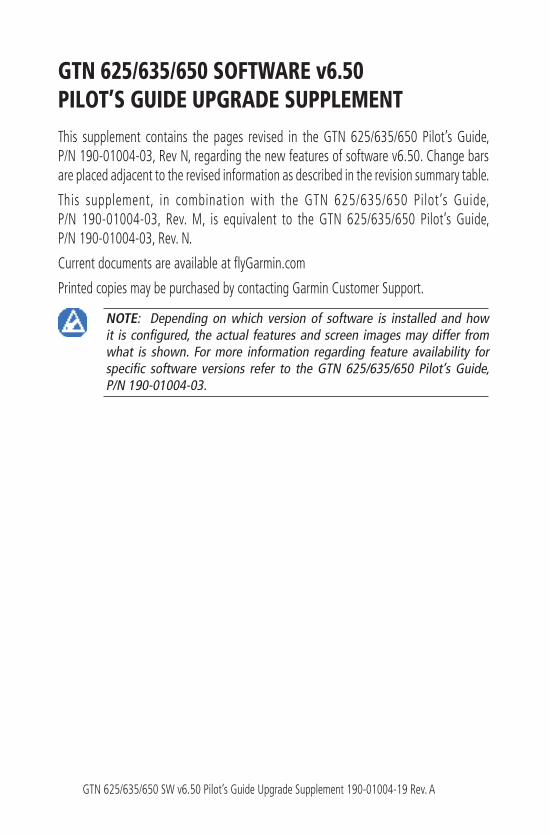
4.2 Active Flight Plan PageThe Active Flight Plan Page provides information and editing functions for
the flight plan currently in use for navigation. Once you have activated a flight plan, the Active Flight Plan Page shows each waypoint for the flight plan, along with the Desired Track (DTK), Distance (DIST) for each leg and Cumulative Distance (CUM). The data fields are user-selectable and may be changed to display Cumulative Distance (CUM), Distance (DIST), Desired Track (DTK), En Route Safe Altitude (ESA), or Estimated Time of Arrival (ETA).
Origin and Destination Waypoints
Active Leg Navigation
Flight Plan Menu Options
Up/Down Keys to Scroll FPL
Parallel Track Active
DTK Between Legs *
DIST Between Legs *
Figure 4-7 Active Flight Plan Page
* The field types may be changed using the Edit Data Fields function in theFlight Plan page Menu.
4.2.1 Waypoint Options
1. While viewing the Active Flight Plan page, touch the desiredflight plan waypoint. The Waypoint Options menu opens.
Waypoint Options For KLAX
Figure 4-8 Active Flight Plan Wpt Options
2. Touch one of the options to perform the selected action. Cancel the option selection by touching the Back key.
4-6 GTN 625/635/650 Pilot’s Guide 190-01004-03 Rev. N
Foreword
Getting Started
Audio & Xpdr Ctrl
Com/Nav
FPL
Direct-To
Proc
Wpt Info
Map
Traffic
Terrain
Weather
Nearest
Services/Music
Utilities
System
Messages
Symbols
Appendix
Index
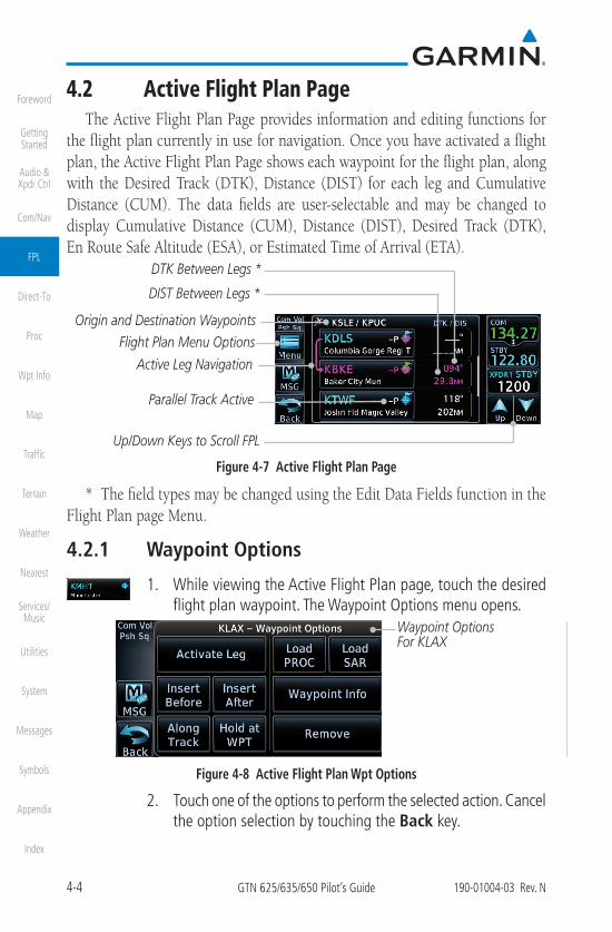
4.2.1.2 Insert Before
The Insert Before option allows you to insert a new waypoint into the active flight plan before the selected waypoint.
1. On the Active Flight Plan page, touch the desired waypoint inthe flight plan. The Waypoint Options list will be displayed.
Insert Before Option Was Selected
Option Will Insert New Waypoint
Before This Selected Flight Plan Waypoint
Figure 4-11 Active Flight Plan Insert Waypoint Before Option
2. Touch the Insert Before key to select a new waypoint beforethe selected waypoint.
3. Select a waypoint identifier with the alphanumeric keypad.
Choose New Waypoint To Insert Before
Selected Flight Plan Waypoint
Figure 4-12 Use the Alphanumeric Keypad to Select Waypoint to Insert Before
4. Then, touch Enter to confirm the selection or touch Cancelto cancel any changes. The new flight plan will be shown.
New Waypoint Inserted Before Selected Flight Plan Waypoint
Figure 4-13 New Waypoint Is Inserted Before the Selected Waypoint

4-7190-01004-03 Rev. N GTN 625/635/650 Pilot’s Guide
Foreword
Getting Started
Audio & Xpdr Ctrl
Com/Nav
FPL
Direct-To
Proc
Wpt Info
Map
Traffic
Terrain
Weather
Nearest
Services/Music
Utilities
System
Messages
Symbols
Appendix
Index
Selected Flight Plan Waypoint
New Flight Plan Waypoint
Figure 4-14 Flight Plan Before and After New Waypoint Inserted
4.2.1.3 Insert After
The Insert After option allows you to insert a new waypoint into the active flight plan after the selected waypoint.
1. On the Active Flight Plan page, touch the desired waypoint inthe flight plan. The Waypoint Options list will be displayed.
2. Touch the Insert After key to select a new waypoint after theselected waypoint.
3. Select a waypoint identifier with the alphanumeric keypad.Then, touch Enter to confirm the selection, or touch theCancel key to cancel the operation and return to the WaypointOptions window.
4.2.1.4 Along Track Offsets
NOTE: This feature is available in software v6.50 and later.
An along track (ATK) represents a temporary lateral position (or checkpoint) relative to an existing waypoint in the flight plan. Offset distance values range between 1 nm and 200 nm, and may be specified in 1 nm increments.
Unlike database waypoints, ATKs indicate a temporary route fix in the flight plan. Once created, their position remains fixed until deleted by the pilot. Subsequent changes to the flight plan do not update the ATK's position.
ATKs appear in flight plan route depictions on the Active Flight Plan and Map pages.

4-8 GTN 625/635/650 Pilot’s Guide 190-01004-03 Rev. N
Foreword
Getting Started
Audio & Xpdr Ctrl
Com/Nav
FPL
Direct-To
Proc
Wpt Info
Map
Traffic
Terrain
Weather
Nearest
Services/Music
Utilities
System
Messages
Symbols
Appendix
Index
ATK Identifier And Distance From
Reference Waypoint
Reference Waypoint
Figure 4-15 ATK Inserted Before Reference Waypoint
Inserting the ATK before the selected waypoint results in a negative offset value. Inserting it after the selected waypoint results in a positive value. The flight plan allows multiple entries.
Selecting Before Automatically
Assigns A Negative Value
Figure 4-16 Along Track Offset Keypad
Once entered, offset distances are not editable. If the offset requires adjustment, delete the existing ATK from the flight plan, and then create a new ATK with the correct offset distance.
Map indications include a dedicated icon and an identifier label. The identifier label denotes the adjacent waypoint's ID and offset distance from the specified ATK.
ATK Icon Offset Identifier Label
Figure 4-17 ATK Indications on Map Page

4-9190-01004-03 Rev. N GTN 625/635/650 Pilot’s Guide
Foreword
Getting Started
Audio & Xpdr Ctrl
Com/Nav
FPL
Direct-To
Proc
Wpt Info
Map
Traffic
Terrain
Weather
Nearest
Services/Music
Utilities
System
Messages
Symbols
Appendix
Index
To create an ATK:
1. While viewing the Active Flight Plan page, select a waypoint.The Waypoint Options menu opens.
2. Touch the Along Track key.
3. Specify an offset distance using the controls on the keypad.
4. Select Before or After to place the ATK before or after thereference waypoint.
5. Touch Enter.
To create an ATK for an altitude constraint:
1. While viewing the Active Flight Plan page, select an altitudeconstraint. The VNAV Options menu opens.
2. Touch the Along Track key.
3. Specify an offset distance using the controls on the keypad.
4. Select Before or After to place the ATK before or after thereference waypoint.
5. Touch Enter and then Save.
4.2.1.5 Remove
The Remove option allows you to remove the selected waypoint from the active flight plan.
1. On the Active Flight Plan page, touch the desired waypoint inthe flight plan. The Waypoint Options menu opens.
2. Touch Remove and then OK.
4-23190-01004-03 Rev. N GTN 625/635/650 Pilot’s Guide
Foreword
Getting Started
Audio & Xpdr Ctrl
Com/Nav
FPL
Direct-To
Proc
Wpt Info
Map
Traffic
Terrain
Weather
Nearest
Services/Music
Utilities
System
Messages
Symbols
Appendix
Index
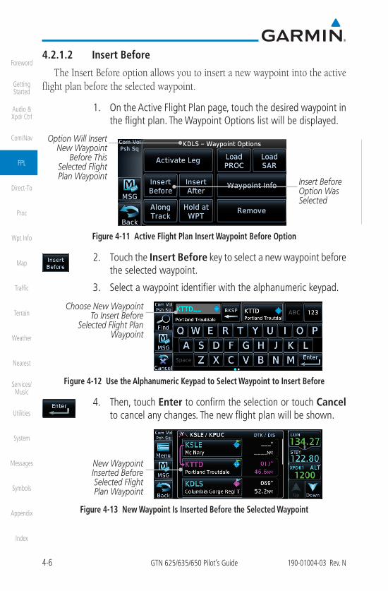
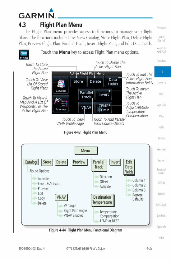
4.3 Flight Plan MenuThe Flight Plan menu provides access to functions to manage your flight
plans. The functions included are: View Catalog, Store Flight Plan, Delete Flight Plan, Preview Flight Plan, Parallel Track, Invert Flight Plan, and Edit Data Fields.
Touch the Menu key to access Flight Plan menu options.
Touch To Invert The Active Flight Plan
Touch To Delete The Active Flight Plan
Touch To View List Of Stored
Flight Plans
Touch To Store The Active Flight Plan
Touch To View A Map And A List Of Waypoints For The
Active Flight Plan
Touch To Edit The Active Flight Plan Information Fields
Touch To View VNAV Profile Page
Touch To Add Parallel Track Course Offsets
Touch To Adjust Altitude Temperature Compensation
Figure 4-43 Flight Plan Menu
Menu
InvertStore
ActivateInvert & ActivatePreviewEditCopyDelete
Route Options
Catalog Delete Preview Parallel Track
DirectionOffsetActivate
Edit Data Fields
Column 1Column 2Column 3Restore DefaultsVNAV
VS TargetFlight Path AngleVNAV Enabled
Destination Temperature
Temperature CompensationTEMP at DEST
Figure 4-44 Flight Plan Menu Functional Diagram

4-24 GTN 625/635/650 Pilot’s Guide 190-01004-03 Rev. N
Foreword
Getting Started
Audio & Xpdr Ctrl
Com/Nav
FPL
Direct-To
Proc
Wpt Info
Map
Traffic
Terrain
Weather
Nearest
Services/Music
Utilities
System
Messages
Symbols
Appendix
Index
4.3.1 Store Flight PlanA flight plan must be saved to the Catalog to be used in future flights. The
Store Flight Plan function will save the Active Flight Plan to the Catalog.
NOTE: If a flight plan that includes a procedure that has been modified by the pilot is saved into the flight plan catalog, the GTN cannot check the accuracy of that procedure when that flight plan is used on a later flight. It is recommended that flight plans with modified procedures not be saved in the flight plan catalog.
1. While viewing the Active Flight Plan page, touch the Menukey. The Flight Plan menu opens.
2. Touch the Store key to store the current Active Flight Plan intothe Catalog. The flight plan will be named by the beginningand ending waypoints.
3. When a duplicate flight plan is created, the Store key will notbe available and the flight plan will be saved with a numeralat the end of the destination waypoint.
Original Flight Plan
Duplicate Flight Plan
Figure 4-45 Duplicate Flight Plan Naming
4.3.2 Invert Flight Plan
NOTE: Inverting a flight plan removes all ATKs.
This option allows you to reverse the active flight plan and use it for navigation guidance back to your original departure point. The original flight plan stored in the catalog is not affected.
1. While viewing the Active Flight Plan page, touch the Menukey. The Flight Plan menu opens.
2. Touch Invert.

4-25190-01004-03 Rev. N GTN 625/635/650 Pilot’s Guide
Foreword
Getting Started
Audio & Xpdr Ctrl
Com/Nav
FPL
Direct-To
Proc
Wpt Info
Map
Traffic
Terrain
Weather
Nearest
Services/Music
Utilities
System
Messages
Symbols
Appendix
Index
4.3.3 En Route Vertical Navigation
NOTE: This feature is available in software v6.50 and later.
The vertical navigation (VNAV) feature provides vertical profile guidance during the descent phase of flight. Guidance is based on altitude constraints associated with lateral waypoints in the active flight plan. Functions:
• Presents vertical path guidance to the descending path as either a linejoining two waypoints with specified altitudes or a linear deviation from thedesired path (i.e., the vertical angle from the specified waypoint or altitude)
• Integrate vertical waypoints into the active flight plan
• Support both manual and autopilot coupling
4.3.3.1 VNAV Requirements
• Enablement by the installer
• A baro-corrected altitude source
If en route vertical navigation is not enabled, the GTN provides a singlewaypoint vertical calculator. For more information, refer to section 14.1.
For installation details related to en route vertical navigation, consult the AFMS.
4.3.3.2 VNAV Limitations
The GTN allows you to create a vertical navigation path with multiple altitude constraints in the flight plan. These altitudes are removed when the flight plan is stored in the flight plan catalog.
Most flight plan waypoints may be assigned an altitude constraint for use in vertical navigation. Exceptions include:
• Flight plan legs containing headings
• Flight plan legs that terminate at an altitude (e.g., a climb to 1,800 ft beforemaking a turn and proceeding direct to fix)

4-26 GTN 625/635/650 Pilot’s Guide 190-01004-03 Rev. N
Foreword
Getting Started
Audio & Xpdr Ctrl
Com/Nav
FPL
Direct-To
Proc
Wpt Info
Map
Traffic
Terrain
Weather
Nearest
Services/Music
Utilities
System
Messages
Symbols
Appendix
Index
4.3.3.3 VNAV Profile Page
Active vertical navigation profile information displays on the VNAV Profile page. This page is accessible from both the Flight Plan menu and the Utilities page.
Touch to Select Target Vertical Speed
Touch to Toggle VNAV
On or Off
Touch to Select Flight Path Angle
Figure 4-46 VNAV Profile Page
To enable VNAV guidance:1. While viewing the Active Flight Plan page, touch Menu.
2. Select VNAV. The VNAV Profile page opens.
3. Touch VNAV Enabled.
To disable VNAV guidance, touch VNAV Enabled again.
Disabling vertical navigation:
• Invalidates required vertical speed, time to Top of Descent (TOD)/Bottom ofDescent (BOD), and vertical deviation data
• Removes vertical deviation and required vertical speed indications from thePFD
VS Required,Time to TOD/BOD, and Vertical Deviation fields display dashes when VNAV is off
VNAV automatically re-enables when the pilot initiates a Direct-To.
4-27190-01004-03 Rev. N GTN 625/635/650 Pilot’s Guide
Foreword
Getting Started
Audio & Xpdr Ctrl
Com/Nav
FPL
Direct-To
Proc
Wpt Info
Map
Traffic
Terrain
Weather
Nearest
Services/Music
Utilities
System
Messages
Symbols
Appendix
Index
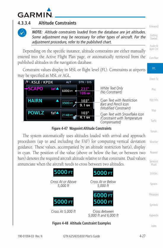
4.3.3.4 Altitude Constraints
NOTE: Altitude constraints loaded from the database are jet altitudes. Some adjustment may be necessary for other types of aircraft. For the adjustment procedure, refer to the published chart.
Depending on the specific instance, altitude constraints are either manually entered into the Active Flight Plan page, or automatically retrieved from the published altitudes in the navigation database.
Constraint values display in MSL or flight level (FL). Constraints at airports may be specified as MSL or AGL.
White Text Only (No Constraint)
Cyan Text with Restriction Bars and Pencil Icon (Modified Constraint)
Cyan Text with Snowflake Icon (Constraint with Temperature Compensated)
Figure 4-47 Waypoint Altitude Constraints
The system automatically uses altitudes loaded with arrival and approach procedures (up to and including the FAF) for computing vertical deviation guidance. These values, accompanied by an altitude restriction bar(s), display in cyan. The position of the value (above or below the bar, or between two bars) denotes the required aircraft altitude relative to that constraint. Dual values annunciate when the aircraft needs to cross between two altitudes.
Cross At or Above 5,000 ft
Cross At or Below 5,000 ft
Cross At 5,000 ft Cross Between 5,000 ft and 6,000 ft
Figure 4-48 Altitude Constraint Examples

4-28 GTN 625/635/650 Pilot’s Guide 190-01004-03 Rev. N
Foreword
Getting Started
Audio & Xpdr Ctrl
Com/Nav
FPL
Direct-To
Proc
Wpt Info
Map
Traffic
Terrain
Weather
Nearest
Services/Music
Utilities
System
Messages
Symbols
Appendix
Index
Indication Color Description
White
• Altitude calculated by system
• Estimate of aircraft altitude as it passes over thenavigation point
• Absence of bar(s) indicates it is not a potentialconstraint
• Altitude retrieved from navigation database
• Bar above and/or below the value indicatesconstraint type
• Altitude is for reference only. Not for use indetermining vertical guidance
Cyan
• Altitude designated for use in determining verticalguidance
• Pencil icon indicates manual designation or manualdata entry
• Constraint invalid
• System cannot use altitude to determine verticalguidance
Table 4-1 Altitude Constraint Color Conventions
An altitude constraint is invalid if:
• Meeting the constraint requires the aircraft to climb
• Meeting the constraint requires the aircraft to exceed the maximum flightpath angle (6° downward) or maximum vertical speed (-4,000 fpm)
• It results in a TOD behind the aircraft's current position
• It is within a leg type that does not support altitude constraints
• It is added to a waypoint past the FAF

4-29190-01004-03 Rev. N GTN 625/635/650 Pilot’s Guide
Foreword
Getting Started
Audio & Xpdr Ctrl
Com/Nav
FPL
Direct-To
Proc
Wpt Info
Map
Traffic
Terrain
Weather
Nearest
Services/Music
Utilities
System
Messages
Symbols
Appendix
Index
The altitude restriction from the database displays when the following three conditions are present.
1. A pilot-specified altitude constraint is deleted
2. Navigation database contains an altitude restriction for the lateralwaypoint
3. A predicted altitude is not available
Once added to the flight plan, an altitude constraint may be modified ordeleted using the controls in the VNAV Options menu. Select a value in the ALT column to display available options.
Selection Function
Type• Opens a list of available constraint types
• Options: At, At or Above, At or Below, and Between
Altitude Data Entry
• Opens a keypad. Specify an altitude value for the selectedconstraint type
• Unit options: MSL, AGL, and Flight LevelRevert Constraint
• Returns a modified altitude constraint to its original publishedvalue
Remove Constraint
• Removes the VNAV designation from the altitude
• Value remains displayed for reference purposes. It is no longerused to compute vertical guidance
• Removing the VNAV designation from an altitude mayinvalidate other displayed altitudes or cause them to changeafter recalculation
Table 4-2 Altitude Constraint Options

4-30 GTN 625/635/650 Pilot’s Guide 190-01004-03 Rev. N
Foreword
Getting Started
Audio & Xpdr Ctrl
Com/Nav
FPL
Direct-To
Proc
Wpt Info
Map
Traffic
Terrain
Weather
Nearest
Services/Music
Utilities
System
Messages
Symbols
Appendix
Index
To designate a waypoint altitude for use with vertical guidance:1. Select a waypoint altitude constraint.
2. Touch Save.
The altitude color changes to cyan, indicating it is usable for vertical guidance.
To enter or modify an altitude constraint:1. Select an altitude constraint.
2. Touch Type and select the constraint type.
3. Select the altitude data key. Enter an altitude constraint valueusing the keypad. Touching Flight Level enters the value asa flight level.
4. Touch Enter to accept the altitude.
5. Touch Save.
To delete an altitude constraint:1. Select an altitude constraint.
2. Touch Remove Constraint.
3. Confirm the request by selecting OK.
To return a modified altitude constraint to its original database value:1. Select an altitude constraint containing the pencil icon.
2. Touch Revert Constraint.
3. Confirm the request by selecting OK.

4-31190-01004-03 Rev. N GTN 625/635/650 Pilot’s Guide
Foreword
Getting Started
Audio & Xpdr Ctrl
Com/Nav
FPL
Direct-To
Proc
Wpt Info
Map
Traffic
Terrain
Weather
Nearest
Services/Music
Utilities
System
Messages
Symbols
Appendix
Index
4.3.3.5 VNAV Direct-To
The VNAV Direct-To function creates a vertical navigation path from the aircraft's current position and altitude to a selected waypoint's location and altitude. By removing any VNAV constraints between the aircraft and the selected waypoint, it allows the pilot to fly the lateral flight plan in a continuous descent and reach the waypoint at the specified altitude.
To initiate a VNAV Direct-To:1. Select an altitude constraint.
2. Touch VNAV Direct-To.
3. Confirm the request by selecting OK.
4.3.3.6 Transition to Approach
Function availability dependent on installer configuration. For more information, refer to the AFMS.
Approach Type VNAV Response
Transition to Approach Enabled
• Vertical path attempts a smooth transition fromen route to approach vertical guidance
• Aircraft intercepts with approach guidance frombelow the glidepath/glideslope
Transition to Approach Not Enabled
• En route VNAV terminates at the waypoint priorto the FAF on approaches with vertical guidance
• En route VNAV terminates at the FAF (LNAV only)Table 4-3 VNAV Approach Response

4-32 GTN 625/635/650 Pilot’s Guide 190-01004-03 Rev. N
Foreword
Getting Started
Audio & Xpdr Ctrl
Com/Nav
FPL
Direct-To
Proc
Wpt Info
Map
Traffic
Terrain
Weather
Nearest
Services/Music
Utilities
System
Messages
Symbols
Appendix
Index
4.3.4 Temperature Compensated Altitude
NOTE: GTNs and TXi displays use only one destination airport temperature for calculating compensated altitudes. Changing the temperature on one of these units automatically recalculates the value across all connected GTNs and GDUs.
A temperature compensation function calculates loaded approach altitudes based on the pilot-specified destination temperature. Once the pilot enters a destination temperature, the system increases the approach altitudes accordingly.
4.3.4.1 Temperature Compensation Requirements
• A destination airport is present in the active flight plan
• GDU 700( )/1060 for access via PFD Minimums menu
4.3.4.2 Setting Temperature Compensated Altitude
Temperature compensation controls are accessible from two locations:
• Destination Temperature Compensation window
• Minimums menu (PFD only)
Uncompensated FAF Altitude
Touch to Enable/Disable
Temperature Compensation
Touch to Enter Destination Temperature
Snowflake Icon Indicates Temperature Compensated FAF Altitude.
Figure 4-49 Destination Temperature Compensation Window
To activate temperature compensated altitude:1. While viewing the Active Flight Plan page, touch Menu.
2. Touch TEMP COMP. The Destination TemperatureCompensation pop-up opens.
3. Touch Temperature Compensation.
4. Touch TEMP at DEST and specify the destination airporttemperature.
The temperature compensated FAF altitude displays in magenta.
4-33190-01004-03 Rev. N GTN 625/635/650 Pilot’s Guide
Foreword
Getting Started
Audio & Xpdr Ctrl
Com/Nav
FPL
Direct-To
Proc
Wpt Info
Map
Traffic
Terrain
Weather
Nearest
Services/Music
Utilities
System
Messages
Symbols
Appendix
Index
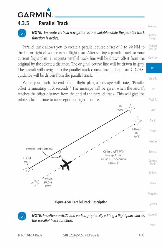
4.3.5 Parallel Track
NOTE: En route vertical navigation is unavailable while the parallel track function is active.
Parallel track allows you to create a parallel course offset of 1 to 99 NM to the left or right of your current flight plan. After setting a parallel track to your current flight plan, a magenta parallel track line will be drawn offset from the original by the selected distance. The original course line will be drawn in gray. The aircraft will navigate to the parallel track course line and external CDI/HSI guidance will be driven from the parallel track.
When you reach the end of the flight plan, a message will state, “Parallel offset terminating in X seconds.” The message will be given when the aircraft reaches the offset distance from the end of the parallel track. This will give the pilot sufficient time to intercept the original course.
Figure 4-50 Parallel Track Description
NOTE: In software v6.21 and earlier, graphically editing a flight plan cancels the parallel track function.

4-35190-01004-03 Rev. N GTN 625/635/650 Pilot’s Guide
Foreword
Getting Started
Audio & Xpdr Ctrl
Com/Nav
FPL
Direct-To
Proc
Wpt Info
Map
Traffic
Terrain
Weather
Nearest
Services/Music
Utilities
System
Messages
Symbols
Appendix
Index
4.3.6 Edit Data FieldsThe Active Flight Plan Page shows each waypoint for the flight plan, along
with the Desired Track (DTK), Distance (DIS) for each leg, and Cumulative Distance (CUM). Data fields are user-selectable and may be changed to display:
ALT - Altitude
CUM - Cumulative Distance
DIS - Distance
DTK - Desired Track
ESA - En Route Safe Altitude
ETA - Estimated Time of Arrival
ETE - Estimated Time En route
FPA - Flight Path Angle
When configured for VNAV, the GTN automatically selects the altitude data field for the first column.
Origin and Destination Waypoints
Current Flight Plan Leg
DTK Between Legs
DIS Between Legs
Figure 4-53 Flight Plan Data Fields
1. While viewing the Flight Plan page, touch the Menu key, andthen the Edit Data Fields key.
Touch To Restore Original Default Types
Current Field Types
Touch To Select Field Types
Figure 4-54 Flight Plan Edit Data Fields Page
2. Touch one of the field keys to select from the list.

4-37190-01004-03 Rev. N GTN 625/635/650 Pilot’s Guide
Foreword
Getting Started
Audio & Xpdr Ctrl
Com/Nav
FPL
Direct-To
Proc
Wpt Info
Map
Traffic
Terrain
Weather
Nearest
Services/Music
Utilities
System
Messages
Symbols
Appendix
Index
Flight Plan Route OptionsSelected
Flight Plan
Figure 4-57 Flight Plan Catalog Route Options
3. Touch the Route Option key for the desired option to act onthe selected flight plan.
4.3.7.1 Catalog Route Option - Activate1. While viewing the Flight Plan Catalog page, touch the desired
flight plan to select it. The Route Options menu will bedisplayed.
2. Touch the Activate key and then touch OK. The selected flightplan will be activated.
Figure 4-58 Touch OK to Replace the Existing Active Flight Plan
3. The Active Flight Plan page will now be displayed.
4.3.7.2 Catalog Route Option - Invert & Activate
NOTE: Inverting a flight plan removes all ATKs.
1. While viewing the Flight Plan Catalog page, touch the desiredflight plan to select it. The Route Options menu will bedisplayed.
2. Touch the Invert & Activate key and then touch OK. Theselected flight plan will be inverted and activated.
5-6 GTN 625/635/650 Pilot’s Guide 190-01004-03 Rev. N
Foreword
Getting Started
Audio & Xpdr Ctrl
Com/Nav
FPL
Direct-To
Proc
Wpt Info
Map
Traffic
Terrain
Weather
Nearest
Services/Music
Utilities
System
Messages
Symbols
Appendix
Index
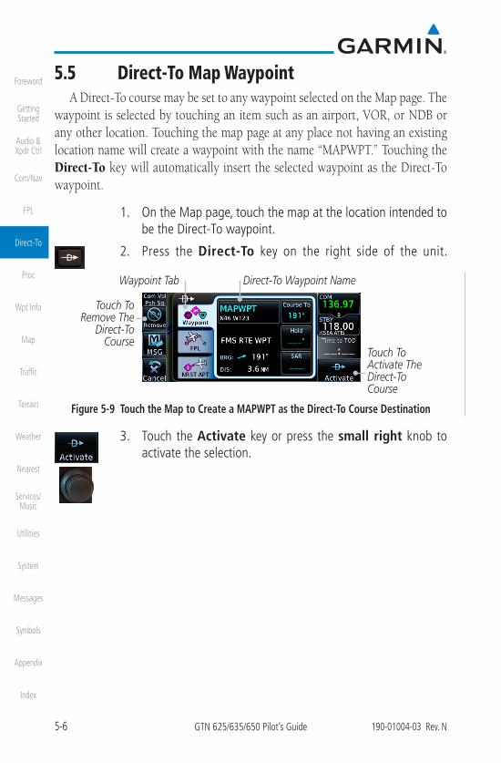
5.5 Direct-To Map WaypointA Direct-To course may be set to any waypoint selected on the Map page. The
waypoint is selected by touching an item such as an airport, VOR, or NDB or any other location. Touching the map page at any place not having an existing location name will create a waypoint with the name “MAPWPT.” Touching the Direct-To key will automatically insert the selected waypoint as the Direct-To waypoint.
1. On the Map page, touch the map at the location intended tobe the Direct-To waypoint.
2. Press the Direct-To key on the right side of the unit.
Touch To Remove The
Direct-To Course
Direct-To Waypoint NameWaypoint Tab
Touch To Activate The Direct-To Course
Figure 5-9 Touch the Map to Create a MAPWPT as the Direct-To Course Destination
3. Touch the Activate key or press the small right knob toactivate the selection.

6-1190-01004-03 Rev. N GTN 625/635/650 Pilot’s Guide
Foreword
Getting Started
Audio & Xpdr Ctrl
Com/Nav
FPL
Direct-To
Proc
Wpt Info
Map
Traffic
Terrain
Weather
Nearest
Services/Music
Utilities
System
Messages
Symbols
Appendix
Index
6 PROCEDURESThe GTN 6XX allows you to fly non-precision and precision approaches to
airports with published instrument approach procedures. The system can also provide visual approach guidance to most airports.
The Procedures Page is displayed by touching the PROC key on the Home page. The Procedures Page provides access to approaches, departures and arrivals. Selections are also shown to: Activate Approach, Vectors to Final, and Activate Missed Approach.
NOTE: Baro-corrected altitude is not required by the GTN unit to meet the requirements of TSO-C146c; however, to take full advantage of the GTN unit's capabilities, an optional baro-corrected altitude source is recommended for (1) automatic sequencing of altitude leg types, and (2) en route vertical navigation. If the GTN does not receive baro-corrected altitude data, altitude leg types require manual sequencing, and en route vertical navigation is not available.
6-4 GTN 625/635/650 Pilot’s Guide 190-01004-03 Rev. N
Foreword
Getting Started
Audio & Xpdr Ctrl
Com/Nav
FPL
Direct-To
Proc
Wpt Info
Map
Traffic
Terrain
Weather
Nearest
Services/Music
Utilities
System
Messages
Symbols
Appendix
Index
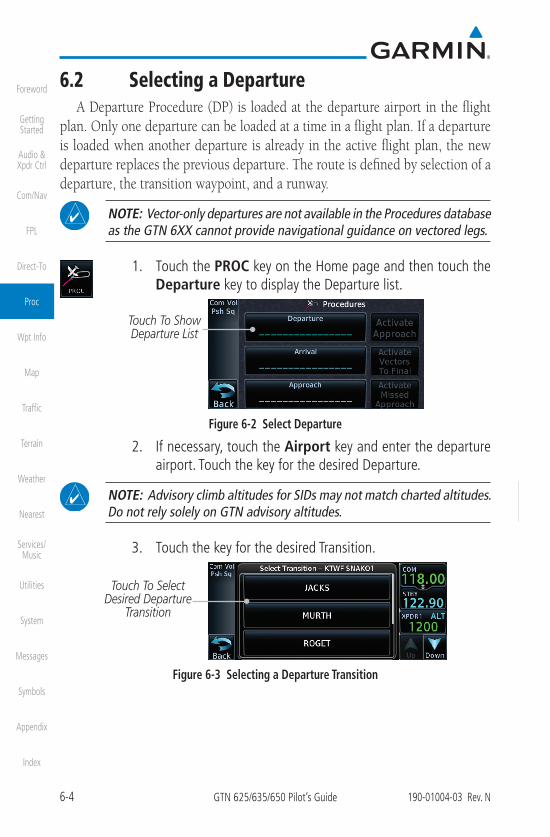
6.2 Selecting a DepartureA Departure Procedure (DP) is loaded at the departure airport in the flight
plan. Only one departure can be loaded at a time in a flight plan. If a departure is loaded when another departure is already in the active flight plan, the new departure replaces the previous departure. The route is defined by selection of a departure, the transition waypoint, and a runway.
NOTE: Vector-only departures are not available in the Procedures database as the GTN 6XX cannot provide navigational guidance on vectored legs.
1. Touch the PROC key on the Home page and then touch theDeparture key to display the Departure list.
Touch To Show Departure List
Figure 6-2 Select Departure
2. If necessary, touch the Airport key and enter the departureairport. Touch the key for the desired Departure.
NOTE: Advisory climb altitudes for SIDs may not match charted altitudes. Do not rely solely on GTN advisory altitudes.
3. Touch the key for the desired Transition.
Touch To Select Desired Departure
Transition
Figure 6-3 Selecting a Departure Transition

6-8 GTN 625/635/650 Pilot’s Guide 190-01004-03 Rev. N
Foreword
Getting Started
Audio & Xpdr Ctrl
Com/Nav
FPL
Direct-To
Proc
Wpt Info
Map
Traffic
Terrain
Weather
Nearest
Services/Music
Utilities
System
Messages
Symbols
Appendix
Index
5. Touch the key for the desired Runway, if necessary. Thecompleted Arrival page will be displayed.
Touch To Display Arrival List For The Selected Airport
Touch To Select Airport
Touch To Display Runway List For The
Selected Arrival
Touch To Select Transition
Touch To Preview Arrival Wpt List And Map
Touch To Load Arrival Into The Active Flight Plan
Figure 6-12 Completed Arrival Page
NOTE: If the selected runway is depicted as RW10B, for instance, this means both runways 10L and 10R.
6. Touch the Preview key. A preview of the Arrival and theSequence List will be displayed.
Sequence List For The Selected
ArrivalArrival
Diagram
Touch To Load Arrival
Figure 6-13 Arrival Map Preview and Sequence List
7. Touch the Load Arrival key to insert the arrival into the flightplan. The Active Flight Plan page will be displayed.
Scroll To View Flight Plan
With Departure Waypoints
Touch To Edit Waypoint
Touch To Select Or Remove
Arrival
Figure 6-14 Flight Plan With Arrival Loaded
NOTE: If using Descent VNAV, verify that the altitudes for the selected procedure match the charted altitudes and are appropriate for the airframe type.

6-9190-01004-03 Rev. N GTN 625/635/650 Pilot’s Guide
Foreword
Getting Started
Audio & Xpdr Ctrl
Com/Nav
FPL
Direct-To
Proc
Wpt Info
Map
Traffic
Terrain
Weather
Nearest
Services/Music
Utilities
System
Messages
Symbols
Appendix
Index
6.4 Selecting an ApproachOnly one approach can be loaded at a time in a flight plan. If an approach
is loaded when another approach is already in the active flight plan, the new approach replaces the previous approach. The route is defined by selection of an approach, the transition waypoint, and a runway.
NOTE: In software v6.21 and later, the pilot may load an alternate approach during a missed approach procedure. The GTN retains all missed approaches in the flight plan.
1. Touch the PROC key on the Home page. The Approach, Arrival, and Departure fields will be dashed until a selection is made.
Touch To Select Departure
Touch To Select Arrival
Touch To Select Approach
Figure 6-15 Procedures Selection Window
2. Touch the Approach key on the Procedures page to selectan approach for the destination airport. Confirm that theintended airport is shown or touch the Airport key and selectthe desired airport.
NOTE: If using Descent VNAV, verify that the altitudes for the selected procedure match the charted or ATC cleared altitudes and are appropriate for the airframe type.
Touch To Select Approach
Touch To Select Airport
Touch To Select Channel ID
Figure 6-16 Selecting an Approach
6-12 GTN 625/635/650 Pilot’s Guide 190-01004-03 Rev. N
Foreword
Getting Started
Audio & Xpdr Ctrl
Com/Nav
FPL
Direct-To
Proc
Wpt Info
Map
Traffic
Terrain
Weather
Nearest
Services/Music
Utilities
System
Messages
Symbols
Appendix
Index
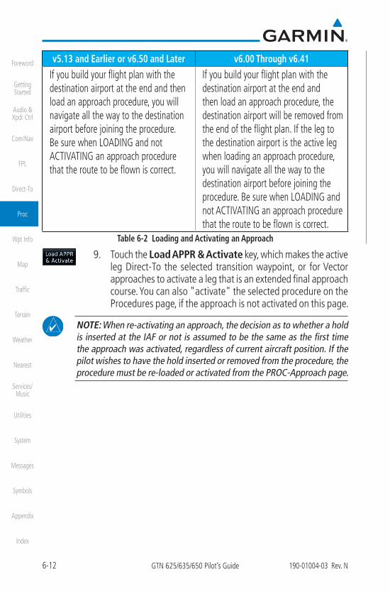
v5.13 and Earlier or v6.50 and Later v6.00 Through v6.41
If you build your flight plan with the destination airport at the end and then load an approach procedure, you will navigate all the way to the destination airport before joining the procedure. Be sure when LOADING and not ACTIVATING an approach procedure that the route to be flown is correct.
If you build your flight plan with the destination airport at the end and then load an approach procedure, the destination airport will be removed from the end of the flight plan. If the leg to the destination airport is the active leg when loading an approach procedure, you will navigate all the way to the destination airport before joining the procedure. Be sure when LOADING and not ACTIVATING an approach procedure that the route to be flown is correct.
Table 6-2 Loading and Activating an Approach
9. Touch the Load APPR & Activate key, which makes the active leg Direct-To the selected transition waypoint, or for Vectorapproaches to activate a leg that is an extended final approachcourse. You can also "activate" the selected procedure on theProcedures page, if the approach is not activated on this page.
NOTE: When re-activating an approach, the decision as to whether a hold is inserted at the IAF or not is assumed to be the same as the first time the approach was activated, regardless of current aircraft position. If the pilot wishes to have the hold inserted or removed from the procedure, the procedure must be re-loaded or activated from the PROC-Approach page.

7-15190-01004-03 Rev. N GTN 625/635/650 Pilot’s Guide
Foreword
Getting Started
Audio & Xpdr Ctrl
Com/Nav
FPL
Direct-To
Proc
Wpt Info
Map
Traffic
Terrain
Weather
Nearest
Services/Music
Utilities
System
Messages
Symbols
Appendix
Index
7.7 User WaypointsNOTE: User airport feature is available in software v6.50 and later.
In addition to the airport, VOR, NDB and intersection information contained in the navigation database, the GTN 6XX allows you to store up to 1,000 user-defined waypoints. The User Waypoint Page displays the waypoint name (up to six characters long), location, and elevation (user airports only).
To minimize nuisance terrain alerting when landing at airports not in the navigation database, user waypoints may be configured as user airports. User airports display on both the Waypoint Info and Nearest Airport pages.
Distance & Bearing To Wpt From
Current PositionIdentifier, Symbol,
& References
Delete Wpt
Wpts Used
View All Wpts
Edit WptDistance & Bearing
To Wpt From Reference Wpt
Touch To View Area Map
Figure 7-21 Waypoint Info for a User Waypoint
7.7.1 Select User Waypoint by Name1. While viewing the User Waypoint page, touch the User
Waypoint Name.
2. Use the keypad to select the characters for the name and thentouch Enter.
7-18 GTN 625/635/650 Pilot’s Guide 190-01004-03 Rev. N
Foreword
Getting Started
Audio & Xpdr Ctrl
Com/Nav
FPL
Direct-To
Proc
Wpt Info
Map
Traffic
Terrain
Weather
Nearest
Services/Music
Utilities
System
Messages
Symbols
Appendix
Index
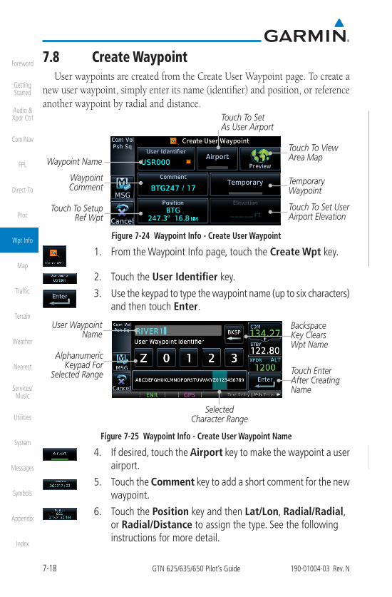
7.8 Create WaypointUser waypoints are created from the Create User Waypoint page. To create a
new user waypoint, simply enter its name (identifier) and position, or reference another waypoint by radial and distance.
Waypoint Name
Waypoint Comment
Temporary Waypoint
Touch To Set User Airport Elevation
Touch To Setup Ref Wpt
Touch To View Area Map
Touch To Set As User Airport
Figure 7-24 Waypoint Info - Create User Waypoint
1. From the Waypoint Info page, touch the Create Wpt key.
2. Touch the User Identifier key.
3. Use the keypad to type the waypoint name (up to six characters)and then touch Enter.
User Waypoint Name
Alphanumeric Keypad For
Selected Range
Backspace Key Clears Wpt Name
Touch Enter After Creating Name
Selected Character Range
Figure 7-25 Waypoint Info - Create User Waypoint Name
4. If desired, touch the Airport key to make the waypoint a userairport.
5. Touch the Comment key to add a short comment for the newwaypoint.
6. Touch the Position key and then Lat/Lon, Radial/Radial,or Radial/Distance to assign the type. See the followinginstructions for more detail.

7-19190-01004-03 Rev. N GTN 625/635/650 Pilot’s Guide
Foreword
Getting Started
Audio & Xpdr Ctrl
Com/Nav
FPL
Direct-To
Proc
Wpt Info
Map
Traffic
Terrain
Weather
Nearest
Services/Music
Utilities
System
Messages
Symbols
Appendix
Index
Touch to Select the Desired Waypoint
Reference Type
Figure 7-26 Waypoint Info - Create User Waypoint Type7. If desired, touch the Temporary? key to create the waypoint
for only temporary use. Temporary waypoints will be removedwhen the power is cycled.
8. For user airports, touch the Elevation key and specify airportelevation.
9. When finished with all selections, touch the Create key tocreate the new waypoint.
7.8.1 Mark On Target
NOTE: This feature is available in software v4.00 and later.
If an external Mark On Target (MOT) switch is installed, pressing that switch will result in the creation of a User waypoint called MOTxxx at the point in space where the MOT switch was pushed. The waypoints are created in increasing numeric order up to number 999, at which point they will start replacing existing waypoints at the beginning of the list.
When a Mark on Target waypoint is created, it may not be immediately visible on the moving map page because the ownship icon will be directly on top of the waypoint. Creation of the waypoint can be verified by changing zoom scales on the map or viewing the User Waypoints page.

7-20 GTN 625/635/650 Pilot’s Guide 190-01004-03 Rev. N
Foreword
Getting Started
Audio & Xpdr Ctrl
Com/Nav
FPL
Direct-To
Proc
Wpt Info
Map
Traffic
Terrain
Weather
Nearest
Services/Music
Utilities
System
Messages
Symbols
Appendix
Index
7.8.2 Waypoint Location Based on LAT/LON 1. From the Create User Waypoint page, touch the Position
key and then the LAT/LON key. Next, touch the Latitude/Longitude value key.
Touch to Select Lat/Lon Waypoint Reference Type
Touch to Select Lat/Lon Values
Figure 7-27 Waypoint Info - Create User Waypoint Type - LAT/LON
2. The Lat/Lon coordinate values will be highlighted. Touch theLat or Lon key to toggle selection of the hemisphere valuesand highlight the selected value. The Large knob may also beused for cursor movement and characters selected with theSmall knob. Use the Large knob to backspace or move thecursor to the left.
Touch to Select Numeric Values
Touch to Select LAT/LON Format
Touch to Toggle Lat/Lon Selection
Touching The Lat Key Activates The Latitude Hemisphere Value for The Selection
Touch to Select Hemisphere Value
Figure 7-28 Waypoint Info - Set Lat/Lon Coordinates
3. Touch the desired hemisphere keys to select the desired values. After selecting the hemisphere value, the cursor will advance to the first character of the adjacent numeric value for selection. Even when the hemisphere values are highlighted, touchinga valid numeric key will always place the cursor at the firstnumeric value.
4. When finished with the Lat/Long selections, touch the Enterkey.
5. When finished with all selections, touch the Create key tocreate the new waypoint.

7-23190-01004-03 Rev. N GTN 625/635/650 Pilot’s Guide
Foreword
Getting Started
Audio & Xpdr Ctrl
Com/Nav
FPL
Direct-To
Proc
Wpt Info
Map
Traffic
Terrain
Weather
Nearest
Services/Music
Utilities
System
Messages
Symbols
Appendix
Index
7.9 Import User Waypoints (Datacard)NOTE: This feature is available in software v5.10 and later.
The GTN can import user generated waypoints from a file on the datacard. The created waypoints will be at the latitude and longitude specified in the file with the specified name and comment. This function overwrites any existing user waypoints with the same name.
When a user waypoint file is on the datacard, a key will be available on the Waypoint Info page for importing user waypoints.
1. Insert a datacard with the User waypoints into the GTN.
2. From the Waypoint Info page, touch the Import Waypointskey.
3. Touch OK to acknowledge the pop-up to import all of the userwaypoints in the file.
Figure 7-31 Start User Waypoint Import4. The pilot is informed of the status of the user waypoint import
via one of the following system messages.
8-9190-01004-03 Rev. N GTN 625/635/650 Pilot’s Guide
Foreword
Getting Started
Audio & Xpdr Ctrl
Com/Nav
FPL
Direct-To
Proc
Wpt Info
Map
Traffic
Terrain
Weather
Nearest
Services/Music
Utilities
System
Messages
Symbols
Appendix
Index
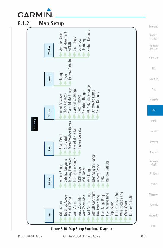
8.1.2 Map Setup
Road
Det
ail
City
Det
ail
Stat
e/Pr
ovin
ce N
ames
Rive
r/Lak
e De
tail
Resto
re D
efau
lts
Rang
eTy
peRe
store
Def
aults
Airp
ort R
ange
Safe
Taxi
Diag
ram
sRu
nway
Ext
ensio
nsIn
terse
ctio
n Ra
nge
NDB
Rang
eVO
R Ra
nge
VRP
Rang
eUs
er W
aypo
int R
ange
Airw
ay R
ange
TFRs
Resto
re D
efau
lts
Smar
t Airs
pace
Show
Airs
pace
sCl
ass B
/TM
A Ra
nge
Clas
s C/T
CA R
ange
Clas
s D R
ange
Restr
icted
Ran
geM
OA (M
ilitar
y) Ra
nge
Othe
r/ADI
Z Ra
nge
Resto
re D
efau
lts
Wea
ther
Sou
rce
Cell
Mov
emen
tM
ETAR
Clou
d To
psEc
ho To
psLig
htni
ngRe
store
Def
aults
Orien
tatio
nNo
rth U
p Ab
ove
Visu
al A
PPR
Sel
Auto
Zoo
mAu
to Z
oom
Min
Auto
Zoo
m M
axTra
ck V
ecto
r Len
gth
Altit
ude
Cons
train
tsNa
v Ran
ge R
ing
Fuel
Rang
e Ri
ngFu
el Re
serv
e Tim
eTo
po S
cale
Poin
t Obs
tacle
Rng
Wire
Obs
tacle
Rng
Char
t Col
orRe
store
Def
aults
Figure 8-10 Map Setup Functional Diagram
8-11190-01004-03 Rev. N GTN 625/635/650 Pilot’s Guide
Foreword
Getting Started
Audio & Xpdr Ctrl
Com/Nav
FPL
Direct-To
Proc
Wpt Info
Map
Traffic
Terrain
Weather
Nearest
Services/Music
Utilities
System
Messages
Symbols
Appendix
Index
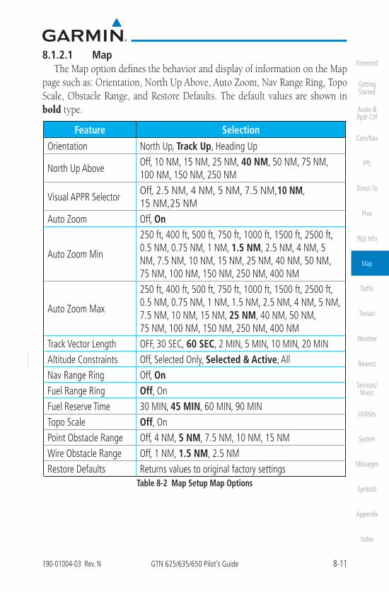
8.1.2.1 MapThe Map option defines the behavior and display of information on the Map
page such as: Orientation, North Up Above, Auto Zoom, Nav Range Ring, Topo Scale, Obstacle Range, and Restore Defaults. The default values are shown in bold type.
Feature Selection
Orientation North Up, Track Up, Heading Up
North Up AboveOff, 10 NM, 15 NM, 25 NM, 40 NM, 50 NM, 75 NM, 100 NM, 150 NM, 250 NM
Visual APPR SelectorOff, 2.5 NM, 4 NM, 5 NM, 7.5 NM,10 NM, 15 NM,25 NM
Auto Zoom Off, On
Auto Zoom Min
250 ft, 400 ft, 500 ft, 750 ft, 1000 ft, 1500 ft, 2500 ft, 0.5 NM, 0.75 NM, 1 NM, 1.5 NM, 2.5 NM, 4 NM, 5 NM, 7.5 NM, 10 NM, 15 NM, 25 NM, 40 NM, 50 NM, 75 NM, 100 NM, 150 NM, 250 NM, 400 NM
Auto Zoom Max
250 ft, 400 ft, 500 ft, 750 ft, 1000 ft, 1500 ft, 2500 ft, 0.5 NM, 0.75 NM, 1 NM, 1.5 NM, 2.5 NM, 4 NM, 5 NM, 7.5 NM, 10 NM, 15 NM, 25 NM, 40 NM, 50 NM, 75 NM, 100 NM, 150 NM, 250 NM, 400 NM
Track Vector Length OFF, 30 SEC, 60 SEC, 2 MIN, 5 MIN, 10 MIN, 20 MINAltitude Constraints Off, Selected Only, Selected & Active, AllNav Range Ring Off, OnFuel Range Ring Off, OnFuel Reserve Time 30 MIN, 45 MIN, 60 MIN, 90 MINTopo Scale Off, OnPoint Obstacle Range Off, 4 NM, 5 NM, 7.5 NM, 10 NM, 15 NMWire Obstacle Range Off, 1 NM, 1.5 NM, 2.5 NMRestore Defaults Returns values to original factory settings
Table 8-2 Map Setup Map Options

8-15190-01004-03 Rev. N GTN 625/635/650 Pilot’s Guide
Foreword
Getting Started
Audio & Xpdr Ctrl
Com/Nav
FPL
Direct-To
Proc
Wpt Info
Map
Traffic
Terrain
Weather
Nearest
Services/Music
Utilities
System
Messages
Symbols
Appendix
Index
Altitude Constraints
NOTE: This feature is available in software v6.50 and later.
Enabling this feature displays altitude constraints from the flight plan. The active constraint is the altitude to which VNAV is currently providing guidance. For more information about altitude constraints, refer to section 4.3.3.
Active Altitude
Constraint
To view a constraint
value, select the associated
waypoint
Figure 8-18 Altitude Constraints
8-42 GTN 625/635/650 Pilot’s Guide 190-01004-03 Rev. N
Foreword
Getting Started
Audio & Xpdr Ctrl
Com/Nav
FPL
Direct-To
Proc
Wpt Info
Map
Traffic
Terrain
Weather
Nearest
Services/Music
Utilities
System
Messages
Symbols
Appendix
Index
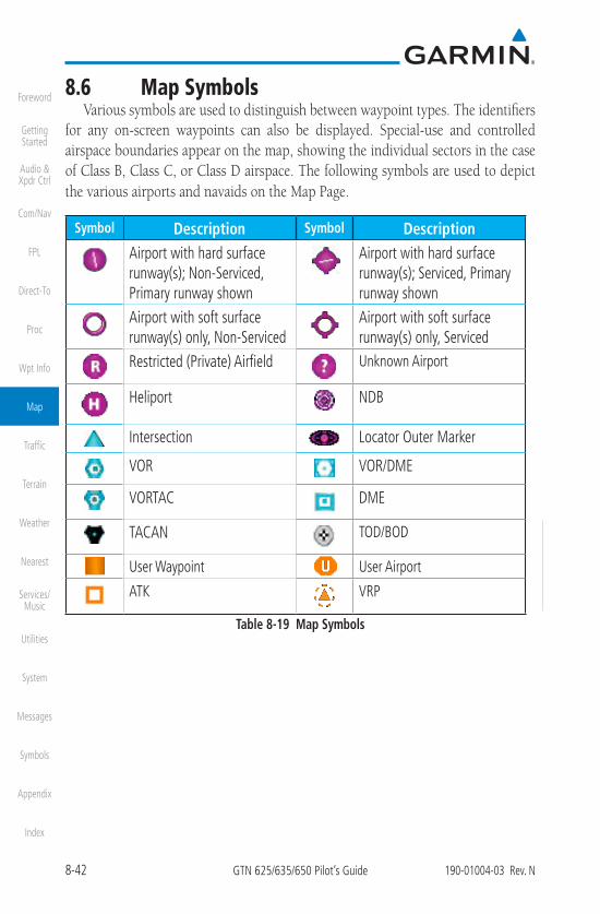
8.6 Map SymbolsVarious symbols are used to distinguish between waypoint types. The identifiers
for any on-screen waypoints can also be displayed. Special-use and controlled airspace boundaries appear on the map, showing the individual sectors in the case of Class B, Class C, or Class D airspace. The following symbols are used to depict the various airports and navaids on the Map Page.
Symbol Description Symbol DescriptionAirport with hard surface runway(s); Non-Serviced, Primary runway shown
Airport with hard surface runway(s); Serviced, Primary runway shown
Airport with soft surface runway(s) only, Non-Serviced
Airport with soft surface runway(s) only, Serviced
Restricted (Private) Airfield Unknown Airport
Heliport NDB
Intersection Locator Outer Marker
VOR VOR/DME
VORTAC DME
TACAN TOD/BOD
User Waypoint User Airport
ATK VRP
Table 8-19 Map Symbols

9-19190-01004-03 Rev. N GTN 625/635/650 Pilot’s Guide
Foreword
Getting Started
Audio & Xpdr Ctrl
Com/Nav
FPL
Direct-To
Proc
Wpt Info
Map
Traffic
Terrain
Weather
Nearest
Services/Music
Utilities
System
Messages
Symbols
Appendix
Index
9.5.1 Traffic Applications - SURF, AIRB, etc.The GTN ADS-B traffic display is capable of running in two “modes:”
Airborne Situational Awareness (AIRB) and Surface Situation Awareness (SURF).
AIRB is in operation in the en route environment, outside of five NM from and 1,500 feet above the nearest airport.
SURF is in operation within the terminal environment (within five NM and less than 1,500 feet above field elevation). When SURF is running, and the zoom scale on the traffic display is less than two NM, the airport environment (including taxiways and runways) is displayed in addition to traffic. This is to aid in situational awareness of runway occupancy/availability, etc.
Due to the varying precision of the data received via ADS-B, ADS-R, and TIS-B, all traffic targets may not be depicted on the traffic display. Because higher data precision is required for display in the SURF environment, some targets eligible for AIRB will not be displayed while SURF is active. Individual eligibility for AIRB and SURF is depicted in the selected traffic data on the traffic page.
9.5.2 ADS-B Traffic MenuThe Traffic Menu allows control of the traffic information display.
Select Altitude Filter: Normal, Above, Below, Unrestricted
Touch To Perform Traffic Test
Toggle ADS-B Traffic Display
Select Motion Vector:Absolute, Relative,
OffSelect Vector Duration: 30 sec, 1 min, 2 min, 5 min
Select TCAS Status:Operate and Standby
Figure 9-11 ADS-B Traffic Menu
9.5.2.1 ADS-B Display Touching ADS-B Display toggles the display of ADS-B traffic and
ADS-B traffic alerting.

10-1190-01004-03 Rev. N GTN 625/635/650 Pilot’s Guide
Foreword
Getting Started
Audio & Xpdr Ctrl
Com/Nav
FPL
Direct-To
Proc
Wpt Info
Map
Traffic
Terrain
Weather
Nearest
Services/Music
Utilities
System
Messages
Symbols
Appendix
Index
10 TERRAIN
10.1 Terrain ConfigurationsNOTE: Obstacles are removed from the Terrain and TAWS pages at ranges greater than 10 NM.
During power-up of the GTN 6XX, the terrain/obstacle database versions are displayed along with a disclaimer. At the same time, the Terrain system self-test begins. A failure message is issued if the terrain test fails.
Garmin provides the following terrain awareness solutions within the GTN 6XX environment.
Alerting functions are designed to increase situational awareness and help reduce controlled flight into terrain (CFIT).
Terrain Type Features
(H)TerrainProximity
• Standard terrain function displaying relative elevations onmoving map
• Does not provide aural or visual alerts
(H)TerrainAlerting
• Basic terrain alerting function
• Provides aural and visual alerts
• Does not meet TSO-C151c or TSO-C194 requirements forcertification
HTAWS• Optional terrain alerting function for rotorcraft
• Satisfies TSO-C194 requirements for certification
TAWS-A• Optional TSO-C151c Class A terrain alerting system
• Provides aural and visual alerts when terrain and obstacles arewithin a given altitude threshold from the aircraft
TAWS-B• Optional TSO-C151c Class B terrain alerting system
• Provides aural and visual alertsTable 10-1 Terrain Configurations

10-2 GTN 625/635/650 Pilot’s Guide 190-01004-03 Rev. N
Foreword
Getting Started
Audio & Xpdr Ctrl
Com/Nav
FPL
Direct-To
Proc
Wpt Info
Map
Traffic
Terrain
Weather
Nearest
Services/Music
Utilities
System
Messages
Symbols
Appendix
Index
10.2 GPS Altitude for TerrainGPS altitude is derived from satellite measurements. To require an accurate
3-D fix (latitude, longitude, altitude), a minimum of four operating satellitesmust be in view of the GPS receiver antenna.
The terrain system uses GPS altitude and position data to:
• Create a 2-D image of surrounding terrain and obstacles relative to theaircraft's position and altitude
• Calculate the aircraft's flight path in relation to surrounding terrain andobstacles
• Predict hazardous terrain conditions and issue alerts
10.2.1 GSL Altitude & Indicated AltitudeThe GTN converts GPS altitude data to GSL altitude (i.e., the geometric
altitude relative to MSL) for use in terrain functions. All Terrain page depictions and elevation indications are in GSL.
Variations between GSL altitude and the aircraft's corrected barometric altitude (or indicated altitude) are common. As a result, Terrain page altitude data may differ from current altimeter readings. Both GSL altitude and indicated altitude represent height above MSL, but differ in accuracy and reliability.
Altitude Type Features
GSL
• Highly accurate and reliable geometric altitude source
• Does not require local altimeter settings to determine heightabove MSL
• Not subject to pressure and temperature variations
• Affected primarily by satellite geometry
Indicated
• Barometric altitude source corrected for pressure variations
• Requires frequent altimeter setting adjustment to determineheight above MSL
• Subject to local atmospheric conditions
• Affected by variations in pressure, temperature, and lapse rateTable 10-2 GSL and Indicated Altitude Features

10-10 GTN 625/635/650 Pilot’s Guide 190-01004-03 Rev. N
Foreword
Getting Started
Audio & Xpdr Ctrl
Com/Nav
FPL
Direct-To
Proc
Wpt Info
Map
Traffic
Terrain
Weather
Nearest
Services/Music
Utilities
System
Messages
Symbols
Appendix
Index
10.5 Terrain Alerting Terrain alerting functions increase situational awareness and help reduce
controlled flight into terrain (CFIT). Visual and aural annunciations alert the pilot when terrain and obstacles are within the given altitude threshold from the aircraft.
10.5.1 Terrain Alerting Requirements• A valid terrain/obstacle database
• A valid 3-D GPS position solution
10.5.2 Terrain Alerting Limitations
NOTE: The data contained in the databases comes from governmentagencies. Garmin accurately processes and cross-validates the data but cannot guarantee its accuracy or completeness.
Terrain alerting uses terrain and obstacle information supplied by government sources. Terrain information is based on terrain elevation information in a database that may contain inaccuracies. Individual obstructions may be shown if available in the database. The data undergoes verification by Garmin to confirm accuracy of the content.

10-11190-01004-03 Rev. N GTN 625/635/650 Pilot’s Guide
Foreword
Getting Started
Audio & Xpdr Ctrl
Com/Nav
FPL
Direct-To
Proc
Wpt Info
Map
Traffic
Terrain
Weather
Nearest
Services/Music
Utilities
System
Messages
Symbols
Appendix
Index
10.5.3 Using Terrain AlertingDuring unit power-up, the terrain/obstacle database versions are displayed.
At the same time, the terrain system self-test begins, and one of the following aural messages is generated:
• “Terrain System Test OK”
• “Terrain System Failure”
On the Map page, terrain and obstacles with heights greater than200 feet Above Ground Level (AGL) display in yellow and red. The GTN 6XX adjusts colors automatically as the aircraft altitude changes.
360Arc
View
Flight PlanLegend
Layers
Terrain Alerting InhibitTest Terrain Alerting
Terrain Alerting
Figure 10-5 Terrain Alerting Page Functional Diagram
10.5.4 Displaying Terrain Alerting DataTerrain uses yellow (caution) and red (warning) to depict terrain and obstacles
alerts relative to aircraft altitude. Colors are adjusted automatically as the aircraft altitude changes. The colors and symbols shown below are used to represent terrain, obstacles, and threat locations. Obstacles are removed when more than 2000 ft below the aircraft.

10-12 GTN 625/635/650 Pilot’s Guide 190-01004-03 Rev. N
Foreword
Getting Started
Audio & Xpdr Ctrl
Com/Nav
FPL
Direct-To
Proc
Wpt Info
Map
Traffic
Terrain
Weather
Nearest
Services/Music
Utilities
System
Messages
Symbols
Appendix
Index
Threat Location
Unlighted Obstacle
Projected Flight Path
1000 ft
100 ft Threshold
Terrain more than 1000 ft below the aircraft altitude (Black)
Terrain between 100 ft and 1000 ft below the aircraft altitude (Yellow)
Terrain above or within 100 ft below the aircraftaltitude (Red)
Figure 10-6 Terrain Altitude/Color Correlation for Terrain Proximity
Unlighted Obstacle Lighted Obstacle Threat Location Indicator
Terrain Color
Terrain/Obstacle Location
Alert Level< 1000 ft
AGL> 1000 ft
AGL< 1000 ft
AGL> 1000 ft
AGL
Obst
acle
Sym
bol
Red
Terrain/Obstacle at or within 100 ft below current aircraft altitude
WARNING (Red)
Yellow
Terrain/Obstacle between 100 ft and 1000 ft below current aircraft altitude
CAUTION (Yellow)
White
Terrain/Obstacle between 1000 ft and 2000 ft below current aircraft altitude
Table 10-5 Terrain/Obstacle Colors and Symbology
Tower Windmill Windmill in Group Power Line
Table 10-6 Obstacle Icon Types

10-13190-01004-03 Rev. N GTN 625/635/650 Pilot’s Guide
Foreword
Getting Started
Audio & Xpdr Ctrl
Com/Nav
FPL
Direct-To
Proc
Wpt Info
Map
Traffic
Terrain
Weather
Nearest
Services/Music
Utilities
System
Messages
Symbols
Appendix
Index
Grouped obstacles are shown with an asterisk (as shown in the Windmill in Group example above). The color of the asterisks is tied to the relative altitude of the highest obstacle in the group, not other obstacles within that group. Obstacles are grouped when they would otherwise overlap.
10.5.5 Terrain PageTerrain information is displayed on the Map and Terrain pages. The Terrain
page is specialized to show terrain, obstacle, and threat location data in relation to the aircraft’s current altitude, without clutter from the basemap. Flight plan information (airports, VORs, and other NAVAIDs) included in the flight plan are displayed for reference. If an obstacle and the projected flight path of the aircraft intersect, the display automatically zooms in to the closest threat location on the Terrain page.
Aircraft orientation on this map is always heading up unless there is no valid heading. If orientation is not heading up, it will be track up. Two views are available relative to the position of the aircraft: the 360° default display and the radar-like ARC (120°) display. Map range is adjustable with the In and Out keys from 1 to 200 NM, as indicated by the map range rings (or arcs).
10.5.5.1 Terrain Page Layers1. While viewing the Terrain page, touch the Menu key.
Select Terrain View Select Displayed Layer
Select Terrain Function
Figure 10-7 Terrain Menu
2. Touch the Flight Plan key to toggle the display of the activeflight plan.

10-14 GTN 625/635/650 Pilot’s Guide 190-01004-03 Rev. N
Foreword
Getting Started
Audio & Xpdr Ctrl
Com/Nav
FPL
Direct-To
Proc
Wpt Info
Map
Traffic
Terrain
Weather
Nearest
Services/Music
Utilities
System
Messages
Symbols
Appendix
Index
Terrain Overlay
Flight Plan
Alert Annunciation
Terrain Legend
Obstacles
Icon shows point obstacle overlay is active (software v5.12 or later)
Icon shows wire obstacle overlay is active (software v5.12 or later)
Figure 10-8 Flight Plan and Legend Shown On Terrain Page
3. Touch the Legend key and select a legend for display on theTerrain page. Options include terrain, obstacle, and off.
10.5.5.2 Terrain Page View
Select the 120º Arc or 360º rings overlay for the Terrain page with either the 360º or Arc keys from the Menu.
1. While viewing the Terrain page, touch the Menu key.
2. Touch the 360º or Arc key.
10.5.5.3 Terrain Alerting SelectionsAn inhibit function allows you to manually inhibit aural terrain alerts. After
cycling power, terrain alerting functions will no longer be inhibited.
1. While viewing the Terrain page, touch the Menu key.
2. Touch the Terrain Inhibit key to toggle the inhibiting of terrainalerts.
3. Touch the Test Terrain key to perform an internal test of theterrain alerting system. This function is not available when theaircraft is in the air.

10-15190-01004-03 Rev. N GTN 625/635/650 Pilot’s Guide
Foreword
Getting Started
Audio & Xpdr Ctrl
Com/Nav
FPL
Direct-To
Proc
Wpt Info
Map
Traffic
Terrain
Weather
Nearest
Services/Music
Utilities
System
Messages
Symbols
Appendix
Index
10.5.6 Terrain AlertsAlerts are issued when flight conditions meet parameters that are set within
terrain alerting software algorithms. When an alert is issued, visual annunciations are displayed and aural alerts are simultaneously issued. Alert types are shown in the Terrain Alerts Summary with corresponding annunciations and aural messages.
When an alert is issued, annunciations appear on the Terrain page. If the page is not displayed at the time, a pop-up alert appears over the page being viewed.
Blinking Message
Touch To Display Terrain Page
Touch To Remove Pop-Up And Remain
On Current PageAlert Annunciation
Figure 10-9 Terrain Alert Pop-Up
To acknowledge the pop-up alert:
Touch the Go to Terrain key (accesses the Terrain page)
OR
Touch the Close key to remove the pop-up alert
If the pilot takes no action, the pop-up will be removed when the alert is no longer active.

10-16 GTN 625/635/650 Pilot’s Guide 190-01004-03 Rev. N
Foreword
Getting Started
Audio & Xpdr Ctrl
Com/Nav
FPL
Direct-To
Proc
Wpt Info
Map
Traffic
Terrain
Weather
Nearest
Services/Music
Utilities
System
Messages
Symbols
Appendix
Index
10.5.6.1 Terrain Alerting Colors and SymbologyColor and symbols are also associated with terrain alerts. The three alert
levels and their associated text coloring as well as any associated symbology are shown in the following table.
Alert Level Annunciator Text Threat Location Indicator
Example Visual Annunciation
Warning White text on red background
Caution Black text on yellow background
Informational Black text on white background
Not Applicable
Table 10-7 Terrain Alert Colors and Symbology
Alert TypeAlert
AnnunciationAural Message
FLTA Terrain Warning(RTC-W, ITI-W)
“Terrain Ahead, Pull Up; Terrain Ahead, Pull Up”*
or “Terrain, Terrain; Pull Up, Pull Up”
FLTA Obstacle Warning (ROC-W, IOI-W)
“Obstacle Ahead, Pull Up; Obstacle Ahead, Pull Up”*
or “Obstacle, Obstacle; Pull Up, Pull Up”
FLTA Wire Warning (ILI-W, RLC-W)
"Wire Ahead Pull Up, Wire Ahead Pull Up"
FLTA Terrain Caution (RTC-C, ITI-C)
“Terrain Ahead; Terrain Ahead”* or
“Caution, Terrain; Caution, Terrain”FLTA Obstacle Caution
(ROC-C, IOI-C)“Obstacle Ahead; Obstacle Ahead”*
or “Caution, Obstacle; Caution, Obstacle”
FLTA Wire Caution (ILI-C, RLC-C)
"Wire Ahead"
Premature Descent Alert Caution (PDA)
“Too Low, Terrain”
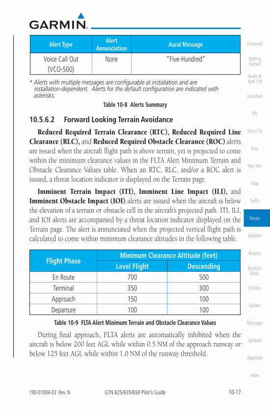
10-17190-01004-03 Rev. N GTN 625/635/650 Pilot’s Guide
Foreword
Getting Started
Audio & Xpdr Ctrl
Com/Nav
FPL
Direct-To
Proc
Wpt Info
Map
Traffic
Terrain
Weather
Nearest
Services/Music
Utilities
System
Messages
Symbols
Appendix
Index
Alert TypeAlert
AnnunciationAural Message
Voice Call Out(VCO-500)
None “Five-Hundred”
* Alerts with multiple messages are configurable at installation and areinstallation-dependent. Alerts for the default configuration are indicated withasterisks.
Table 10-8 Alerts Summary
10.5.6.2 Forward Looking Terrain Avoidance
Reduced Required Terrain Clearance (RTC), Reduced Required Line Clearance (RLC), and Reduced Required Obstacle Clearance (ROC) alerts are issued when the aircraft flight path is above terrain, yet is projected to come within the minimum clearance values in the FLTA Alert Minimum Terrain and Obstacle Clearance Values table. When an RTC, RLC, and/or a ROC alert is issued, a threat location indicator is displayed on the Terrain page.
Imminent Terrain Impact (ITI), Imminent Line Impact (ILI), and Imminent Obstacle Impact (IOI) alerts are issued when the aircraft is below the elevation of a terrain or obstacle cell in the aircraft’s projected path. ITI, ILI, and IOI alerts are accompanied by a threat location indicator displayed on the Terrain page. The alert is annunciated when the projected vertical flight path is calculated to come within minimum clearance altitudes in the following table.
Flight PhaseMinimum Clearance Altitude (feet)
Level Flight DescendingEn Route 700 500Terminal 350 300Approach 150 100Departure 100 100
Table 10-9 FLTA Alert Minimum Terrain and Obstacle Clearance Values
During final approach, FLTA alerts are automatically inhibited when the aircraft is below 200 feet AGL while within 0.5 NM of the approach runway or below 125 feet AGL while within 1.0 NM of the runway threshold.
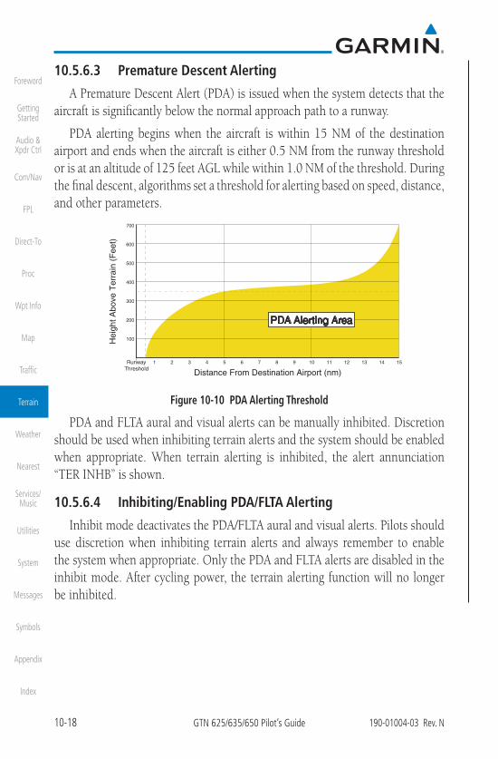
10-18 GTN 625/635/650 Pilot’s Guide 190-01004-03 Rev. N
Foreword
Getting Started
Audio & Xpdr Ctrl
Com/Nav
FPL
Direct-To
Proc
Wpt Info
Map
Traffic
Terrain
Weather
Nearest
Services/Music
Utilities
System
Messages
Symbols
Appendix
Index
10.5.6.3 Premature Descent Alerting
A Premature Descent Alert (PDA) is issued when the system detects that the aircraft is significantly below the normal approach path to a runway.
PDA alerting begins when the aircraft is within 15 NM of the destination airport and ends when the aircraft is either 0.5 NM from the runway threshold or is at an altitude of 125 feet AGL while within 1.0 NM of the threshold. During the final descent, algorithms set a threshold for alerting based on speed, distance, and other parameters.
700
600
500
400
300
200
100Hei
ght A
bove
Ter
rain
(F
eet)
Distance From Destination Airport (nm) 1 2 3 4 5 6 7 8 9 10 11 12 13 14 15
PDA Alerting AreaPDA Alerting Area
RunwayThreshold
Figure 10-10 PDA Alerting Threshold
PDA and FLTA aural and visual alerts can be manually inhibited. Discretion should be used when inhibiting terrain alerts and the system should be enabled when appropriate. When terrain alerting is inhibited, the alert annunciation “TER INHB” is shown.
10.5.6.4 Inhibiting/Enabling PDA/FLTA Alerting
Inhibit mode deactivates the PDA/FLTA aural and visual alerts. Pilots should use discretion when inhibiting terrain alerts and always remember to enable the system when appropriate. Only the PDA and FLTA alerts are disabled in the inhibit mode. After cycling power, the terrain alerting function will no longer be inhibited.

10-19190-01004-03 Rev. N GTN 625/635/650 Pilot’s Guide
Foreword
Getting Started
Audio & Xpdr Ctrl
Com/Nav
FPL
Direct-To
Proc
Wpt Info
Map
Traffic
Terrain
Weather
Nearest
Services/Music
Utilities
System
Messages
Symbols
Appendix
Index
Terrain Inhibited
Annunciation
Touch to Toggle Terrain Inhibit
Figure 10-11 Terrain Alerting Inhibited Annunciation
1. While viewing the Terrain page, touch the Menu key.
2. Touch the Terrain Inhibit key to inhibit or enable terrainalerting (choice dependent on current state). A green bar inthe key indicates the inhibit function is active.
10.5.6.5 Altitude Voice Call Out (VCO)Terrain provides aural advisory alerts as the aircraft descends, beginning at
500 feet above the terrain, as determined by the radar altimeter (if greater than 5 NM from the nearest airport) or 500 feet above the nearest runway threshold elevation (if less than 5 NM from the nearest airport). Upon descent to this altitude, the terrain system issues the aural alert message “Five-hundred.”
10.5.6.6 Terrain Not Available AlertTerrain requires a 3-D GPS position solution along with specific vertical
accuracy minimums. Should the position solution become degraded or if the aircraft is out of the database coverage area, the annunciation “TER N/A” is generated in the annunciation window and on the Terrain page. The aural message “Terrain Not Available” is generated. When the GPS signal is re-established and the aircraft is within the database coverage area, the aural message “Terrain Available” is generated (when the aircraft is airborne).
10.5.6.7 Terrain Failure AlertTerrain continually monitors several system-critical items such as database
validity, hardware status, and GPS status. If the terrain/obstacle database is not available, the aural message “Terrain System Failure” is generated along with a “TER FAIL” annunciation.

10-20 GTN 625/635/650 Pilot’s Guide 190-01004-03 Rev. N
Foreword
Getting Started
Audio & Xpdr Ctrl
Com/Nav
FPL
Direct-To
Proc
Wpt Info
Map
Traffic
Terrain
Weather
Nearest
Services/Music
Utilities
System
Messages
Symbols
Appendix
Index
10.5.7 Terrain System StatusDuring power-up, the terrain system conducts a self-test of its aural and
visual annunciations. This test can also be manually initiated. An aural alert is issued at test completion. Terrain system testing is disabled when ground speed exceeds 30 knots.
Alert TypeAlert
AnnunciationAural Message
Terrain Available None “Terrain Available”
Terrain System Test in Progress None
Terrain System Test Pass None “Terrain System Test OK”
Terrain N/A Terrain Not Available
Terrain Alerting is Disabled None
Terrain System Test Fail “Terrain System Failure”
Table 10-10 Terrain System Test Status Annunciations

11-32 GTN 625/635/650 Pilot’s Guide 190-01004-03 Rev. N
Foreword
Getting Started
Audio & Xpdr Ctrl
Com/Nav
FPL
Direct-To
Proc
Wpt Info
Map
Traffic
Terrain
Weather
Nearest
Services/Music
Utilities
System
Messages
Symbols
Appendix
Index
Connext Weather coverage is available throughout most of Europe, Canada and the U.S. Additional radar coverage areas are added continuously. For the latest radar coverage information, visit: https://fly.garmin.com/fly-garmin/connext/worldwide-weather/
Various world-wide weather subscription package options provide weather reporting for most of Europe, Canada, Australia, and the U.S.
11.3.1 Using Connext Satellite Weather Products
NOTE: A system can be configured for multiple weather products, but only one may be selected for viewing in the Weather or map pages at a given time.
When a weather product is active on the Weather Data Link Page or the Navigation Map Page, the age of the data is displayed on the screen. The age of the product is based on the time difference between when the data was assembled on the ground and the current GPS time. Weather products are refreshed at selectable intervals.
Weather products expire at intervals based on each product. When the data expires, it is removed from the display. This ensures that the displayed data is consistent with what is currently being broadcast by Connext Satellite Radio services. If more than half of the expiration time has elapsed from the time the data is received, the color of the product age displayed changes to yellow.

11-36 GTN 625/635/650 Pilot’s Guide 190-01004-03 Rev. N
Foreword
Getting Started
Audio & Xpdr Ctrl
Com/Nav
FPL
Direct-To
Proc
Wpt Info
Map
Traffic
Terrain
Weather
Nearest
Services/Music
Utilities
System
Messages
Symbols
Appendix
Index
Waypoint Connext Data Request
1. Touch the Waypoint key to request that weather informationwill be shown around the selected waypoint.
2. Select the waypoint and then press ENT.
Diameter/Route Width Connext Data Request
After selecting a coverage option in the previous section, select the desired Diameter and then press ENT.
11.3.3.3 Connext Weather Map Orientation
1. While viewing the Connext Weather Menu, touch theOrientation key.
2. Touch the orientation choices of North Up, Track Up, andHeading Up and to accept the displayed value and return tothe Connext Weather Menu.
Touch To Select Map Orientation
Figure 11-59 Connext Weather Map Orientation
11.3.4 Register with ConnextTo access Connext Weather, visit flyGarmin.com and create a Connext
Satellite Services account. Be ready to provide the GTN system ID, airframe information (model, tail number), and Iridium serial number. Garmin will issue an access code for entry on the Connext Registration page. If access code and system ID are correct, the airframe registration details will display.
1. While viewing Connext Settings Menu, touch theDatalink Status key.

14-1190-01004-03 Rev. N GTN 625/635/650 Pilot’s Guide
Foreword
Getting Started
Audio & Xpdr Ctrl
Com/Nav
FPL
Direct-To
Proc
Wpt Info
Map
Traffic
Terrain
Weather
Nearest
Services/Music
Utilities
System
Messages
Symbols
Appendix
Index
14 UTILITIESThe Utilities page provides a group of features that make flight planning
easier and more efficient.
Figure 14-1 Utilities Home Page
Feature Description
VNAV 1
• Enable en route vertical guidance
• Specify a target vertical speed and flight path angle
• View active constraint data
VCALC 1 Calculate time to TOD and vertical speed required to reach target altitude at the specified location.
Trip PlanningView DTK, DIS, ETE, ESA and ETA information for a direct-to, point-to-point between two specified waypoints or for any programmed flight plan.
Fuel Planning 2 View fuel conditions along the active direct-to or flight plan.
DALT/TAS/Winds Calculate altitude, airspeed, and winds.

14-2 GTN 625/635/650 Pilot’s Guide 190-01004-03 Rev. N
Foreword
Getting Started
Audio & Xpdr Ctrl
Com/Nav
FPL
Direct-To
Proc
Wpt Info
Map
Traffic
Terrain
Weather
Nearest
Services/Music
Utilities
System
Messages
Symbols
Appendix
Index
Feature Description
RAIM Prediction
Determine GPS coverage availability for the current location or a specified waypoint at any time and date. RAIM performs checks to ensure the GTN unit has adequate satellite geometry during flight.
Flight Timers Monitor time in flight using three available timer types.
Scheduled MessagesCreate custom reminder messages and set when they will display.
Checklists Review a built-in version of the aircraft checklist.Logs Export a flight data log.
Clean ScreenLock touchscreen controls to prevent accidental activation while cleaning the display.Table 14-1 Utilities Page Features
Note 1: VCALC and VNAV functions are mutually exclusive. Enabling one automatically disables the other.
Note 2: Aircraft must be equipped with fuel flow and/or fuel on board sensors.

14-3190-01004-03 Rev. N GTN 625/635/650 Pilot’s Guide
Foreword
Getting Started
Audio & Xpdr Ctrl
Com/Nav
FPL
Direct-To
Proc
Wpt Info
Map
Traffic
Terrain
Weather
Nearest
Services/Music
Utilities
System
Messages
Symbols
Appendix
Index
Gene
ric Ti
mer
Rese
t Tim
er
Star
t/Sto
p
Dire
ctio
n Up Dow
n
Trip
Timer
Rese
t Tim
er
Crite
ria
Pow
er O
nIn
Air
Depa
rture
Tim
e
Rese
t Tim
e
Crite
ria
Pow
er O
nIn
Air
Indi
cate
d AL
TBA
ROCA
STA
TTR
KHD
GGr
ound
Spe
ed
Mod
e
Depa
rt Tim
eDe
part
Date
Grou
nd S
peed
Poin
t to
Poin
t
Fligh
t Pla
n
P.POS
From
To FPL
Leg
Mod
e
Fuel
on B
oard
Fuel
Flow
Grou
nd S
peed
Poin
t to
Poin
t
Fligh
t Pla
n
P.POS
From
To FPL
Leg
MSL
Abov
e Wpt
Altit
ude T
ype
VS P
rofil
e
Offse
tBe
fore
/Afte
r
Targ
et A
ltitu
de
Targ
et W
aypo
int
Resto
re D
efau
lts
Disp
lay M
essa
ges
Way
poin
tAr
rival
Dat
eAr
rival
Tim
eRA
IM S
tatu
s
Com
pute
RA
IM
Mes
sage
Type
Timer
Men
u Grou
pCh
eckli
stCl
ear C
urre
nt
Chec
klist
Clea
r All
Chec
klists
WAA
S Di
agno
stic L
ogFli
ght D
ata
Log
VS Ta
rget
Fligh
t Pat
h An
gle
VNAV
Ena
bled
* *
*VCA
LC a
nd V
NAV
func
tions
are
mut
ually
exc
lusiv
e..
Figure 14-2 Utilities Functional Diagram

14-4 GTN 625/635/650 Pilot’s Guide 190-01004-03 Rev. N
Foreword
Getting Started
Audio & Xpdr Ctrl
Com/Nav
FPL
Direct-To
Proc
Wpt Info
Map
Traffic
Terrain
Weather
Nearest
Services/Music
Utilities
System
Messages
Symbols
Appendix
Index
14.1 Vertical Calculator (VCALC)NOTE: If VNAV is enabled, the VCALC page is replaced with theVNAV Profile page. For more information, refer to section 4.3.3.
The Vertical Calculator (VCALC) function allows you to create a three-dimensional profile which guides you from your present position and altitude to a final (target) altitude at a specified location. This is helpful when you’d like to descend to a certain altitude near an airport. Once the profile is defined, message alerts and additional data can be configured on the Default NAV and Map Pages to keep you informed of your progress.
Cruise Altitude
Target Altitude
Target Offset (Before)
Target Waypoint
Figure 14-3 VCALC TargetVCALC is inhibited in the following conditions:
• Groundspeed is less than 35 knots
• No active flight plan or direct-to destination
• SUSP mode
• Vectors-to-Final mode
• VLOC mode
• After the FAF on an approach
• OBS mode
WARNING: Do not use VCALC messages as the only means of either avoiding terrain/obstacles or following ATC guidance. VCALC provides advisory information only and must be used in concert with all other available navigation data sources.

15-2 GTN 625/635/650 Pilot’s Guide 190-01004-03 Rev. N
Foreword
Getting Started
Audio & Xpdr Ctrl
Com/Nav
FPL
Direct-To
Proc
Wpt Info
Map
Traffic
Terrain
Weather
Nearest
Services/Music
Utilities
System
Messages
Symbols
Appendix
Index
CDIDate/TimeCom/NavNearest AirportKeyboardCrossfill
Serial No. & Sys IDSW/HW Version InfoDatabase Info
SBAS WAAS
Manual Offset
Arrival Destination ProximityClass B/TMAClass C/TCAClass DRestrictedMOA (Military)OtherAirspace Altitude Buffer
VolumeTAWS Alert Voice
Nav AngleMag VarTempFuelPosition Format
Connext Setup *
* Optional
User Fields
Voice Commands *Command History *
Figure 15-2 System Function Summary

15-15190-01004-03 Rev. N GTN 625/635/650 Pilot’s Guide
Foreword
Getting Started
Audio & Xpdr Ctrl
Com/Nav
FPL
Direct-To
Proc
Wpt Info
Map
Traffic
Terrain
Weather
Nearest
Services/Music
Utilities
System
Messages
Symbols
Appendix
Index
15.4 SetupThe System Setup page allows you to:
• Select CDI scale and ILS CDI capture type
• Specify time format and local offset
• Access nearest airport search filtering options
• Access COM/NAV radio settings
• Select keyboard format
• Enable crossfilling to a second GTN or GNS unit
Local OffsetTime Format
Date/Time
Nearest Airport
Reverse Frequency Lookup
CDI
CDI ScaleILS CDI Capture
Runway SurfaceMin Rwy Length
Com Channel Spacing25.0 kHz8.33 kHz
Crossfill
Com/Nav
Keyboard
COM Sidetone Control
Figure 15-19 System Setup Functions

15-16 GTN 625/635/650 Pilot’s Guide 190-01004-03 Rev. N
Foreword
Getting Started
Audio & Xpdr Ctrl
Com/Nav
FPL
Direct-To
Proc
Wpt Info
Map
Traffic
Terrain
Weather
Nearest
Services/Music
Utilities
System
Messages
Symbols
Appendix
Index
1. While viewing the System page, touch the Setup key.Touch to Set Time Format And Offset
Touch To Set Up Com and Nav
Radios
Touch to Enable Crossfill With Dual GTN Units
Touch to Select Nearest Airport Criteria
Touch to Select CDI And ILS CDI
Capture
Touch to Select Keyboard Format
Figure 15-20 System Setup Page
2. After making the desired selections, touch the Back key toreturn to the Setup page.
15.4.1 CDI Scale SelectionThe CDI source and ILS CDI Capture type may be selected manually or
automatically. The selected CDI Scale will be reflected in the annunciation bar at the bottom of the display.
CDI Scale Selection allows you to define the scale for the course deviation indicator (both on the GTN unit's on-screen CDI and the external CDI). The scale values represent full scale deflection for the CDI to either side. The default setting is “Auto.” At this setting, the CDI scale is set to 2.0 NM during the “en route” phase of flight. Within 31 NM (terminal area) of your destination airport, the CDI scale linearly ramps down to 1.0 NM over a distance of 1 NM. Likewise, when leaving your departure airport the CDI scale is set to 1.0 NM and gradually ramps up to 2 NM beyond 30 NM (from the departure airport). During GPS approach operations the CDI scale gradually transitions down to an angular CDI scale. At 2.0 NM before the final approach fix (FAF), CDI scaling is tightened from 1.0 NM to the angular full scale deflection (typically the angular full-scale deflection is 2.0°, but will be as defined for the approach).

15-19190-01004-03 Rev. N GTN 625/635/650 Pilot’s Guide
Foreword
Getting Started
Audio & Xpdr Ctrl
Com/Nav
FPL
Direct-To
Proc
Wpt Info
Map
Traffic
Terrain
Weather
Nearest
Services/Music
Utilities
System
Messages
Symbols
Appendix
Index
15.4.3 Nearest Airport CriteriaNearest Airport Criteria defines the surface type and minimum runway
length used when determining the 25 nearest airports to display on the Nearest Airport Page. A minimum runway length and/or surface type may be entered to prevent the display of airports with small runways, or runways that do not have an appropriate surface. Deselecting Include User Airports excludes user-defined airports from the nearest airport search.
Default settings are “0 feet (or meters)” for runway length and “any” for runway surface type.
1. While viewing the System Setup page, touch theNearest Airport key.
Touch To Select Runway Surface Type
Touch To Select Minimum Runway Length
Touch To Include User Airports
Figure 15-25 Select Nearest Airport Criteria
2. Touch the Runway Surface key to display the options.Select the desired surface type.
Touch To Select Any Runway SurfaceTouch To Select Hard Runway Surfaces OnlyTouch To Select Hard or Soft Runway SurfacesTouch To Select Water Surfaces Only
Figure 15-26 Nearest Airport Runway Surface Type
3. Touch Minimum Runway Length to display the keypadfor selecting the minimum runway length. Select the desiredminimum runway length with the numeric keypad. A selectionof "0" will allow any length.

15-20 GTN 625/635/650 Pilot’s Guide 190-01004-03 Rev. N
Foreword
Getting Started
Audio & Xpdr Ctrl
Com/Nav
FPL
Direct-To
Proc
Wpt Info
Map
Traffic
Terrain
Weather
Nearest
Services/Music
Utilities
System
Messages
Symbols
Appendix
Index
Touch to Set Values
Touch to Delete Values
Figure 15-27 Nearest Airport Minimum Runway Length
4. After selecting the minimum runway length, touch the Enterkey to save the entered values, or touch the Cancel key toreturn to the System Setup page without saving a value.
5. Touch Include User Airports to include or exclude usercreated airports
15.4.4 Com/Nav Setup
15.4.4.1 Com Channel SpacingCom transceiver channel spacing may be selected between 8.33 kHz and
25.0 kHz.
1. While viewing the System Setup page, touch the Com/Navkey.
2. Touch COM Channel Spacing to toggle between 8.33 kHzand 25.0 kHz channel spacing.

15-22 GTN 625/635/650 Pilot’s Guide 190-01004-03 Rev. N
Foreword
Getting Started
Audio & Xpdr Ctrl
Com/Nav
FPL
Direct-To
Proc
Wpt Info
Map
Traffic
Terrain
Weather
Nearest
Services/Music
Utilities
System
Messages
Symbols
Appendix
Index
15.4.4.3 COM Sidetone Control
NOTE: This feature is available in software v6.50 and later. It requires enablement by the installer.
COM sidetone is audio spoken into the COM microphone that is played back in real-time over the headset. An offset setting determines sidetone volume for the COM during radio transmission. Controls allow adjustment of the amount that the COM sidetone volume level is offset from the COM receiver volume or the configured sidetone volume.
Enables Link to COM Receiver
Volume
Offset Adjustment Controls
Range: +/-10%Default Value: 0
Figure 15-29 COM Sidetone Controls
To adjust the offset from the COM receiver volume:
1. While viewing the System Setup page, touch the Com/Navkey.
2. Select Link to COM VOL.
3. Adjust offset as necessary.
To adjust the offset from the configured sidetone volume, deselect Link to COM VOL and then adjust the offset as necessary.
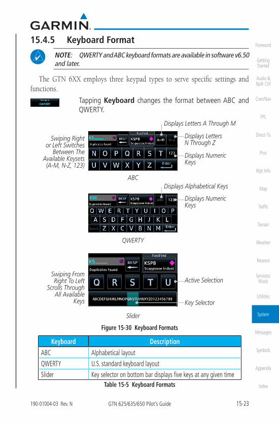
15-23190-01004-03 Rev. N GTN 625/635/650 Pilot’s Guide
Foreword
Getting Started
Audio & Xpdr Ctrl
Com/Nav
FPL
Direct-To
Proc
Wpt Info
Map
Traffic
Terrain
Weather
Nearest
Services/Music
Utilities
System
Messages
Symbols
Appendix
Index
15.4.5 Keyboard Format
NOTE: QWERTY and ABC keyboard formats are available in software v6.50 and later.
The GTN 6XX employs three keypad types to serve specific settings and functions.
Tapping Keyboard changes the format between ABC and QWERTY.
ABC
Displays Letters A Through M
Displays Letters N Through Z
QWERTY
Displays Alphabetical Keys
Displays Numeric Keys
Displays Numeric Keys
Slider
Swiping From Right To Left
Scrolls Through All Available
Keys Key Selector
Active Selection
Swiping Right or Left Switches
Between The Available Keysets (A-M, N-Z, 123)
Figure 15-30 Keyboard Formats
Keyboard Description
ABC Alphabetical layout
QWERTY U.S. standard keyboard layout
Slider Key selector on bottom bar displays five keys at any given timeTable 15-5 Keyboard Formats

15-32 GTN 625/635/650 Pilot’s Guide 190-01004-03 Rev. N
Foreword
Getting Started
Audio & Xpdr Ctrl
Com/Nav
FPL
Direct-To
Proc
Wpt Info
Map
Traffic
Terrain
Weather
Nearest
Services/Music
Utilities
System
Messages
Symbols
Appendix
Index
15.7 Units SettingsThe Units Setup page allows you to select the conventions for the various
units that are displayed.
Units Type Units Values
Altitude/Vertical Speed Feet(FT/FPM), Meters (M/MPS)
Distance/SpeedNautical Miles (NM/KT), Kilometers (KM/KPH), Statue Miles (SM/MPH)
Fuel1Gallons (GAL), Imperial Gallons (IG), Kilograms (KG), Liters (LT), or Pounds (LB)
Nav Angle1 Magnetic (°), True (°T), User (°u)
Magnetic Variation Enter numeric value, E or W
Position FormatLAT/LON DD.D°, LAT/LON DD° MM.M', LAT/TON DD° MM'SS", MGRS, UTM, Swiss Grid, Irish Grid, British National Grid
Pressure Inches of Mercury (IN), Hectopascals (HPA), Millibars (MB)
Temperature1 Celsius (°C) or Fahrenheit (°F)
Table 15-9 System Units SetupNote 1: Only these unit types will be crossfilled in dual GTN installations.
15.7.1 Setup UnitsUse these settings to set the units for values displayed in the unit operation.
1. While viewing the System page, touch the Units key.
Touch To Set Units
Figure 15-41 System Units Page2. Touch the key for the desired units. A window with a list of
unit values will appear. Touch the desired value on the list.

15-35190-01004-03 Rev. N GTN 625/635/650 Pilot’s Guide
Foreword
Getting Started
Audio & Xpdr Ctrl
Com/Nav
FPL
Direct-To
Proc
Wpt Info
Map
Traffic
Terrain
Weather
Nearest
Services/Music
Utilities
System
Messages
Symbols
Appendix
Index
15.7.3 Position Format SelectionThere are multiple position formats available.
LAT/LON DD.D° **
LAT/LON DD°MM.M'
LAT/LON DD°MM'SS" **
British National Grid **
Irish National Grid **
Swiss National Grid **
MGRS *
UTM *
* Software v4.10 and later.** Software v6.50 and later.
The selected format is used in all locations where position information is available.
Grid Designator
100 km Square Identifier
Easting Value
Northing Value
Figure 15-46 MGRS Position Format Detail
Grid ZoneLatitude Band
Easting Value
Northing Value
Figure 15-47 UTM Position Format Detail
In the case of regional position formats (e.g., Swiss National Grid), the GTN defaults to displaying LAT/LON for any positions outside of the grid region.
Grid Designator
Easting Value
Northing Value
Figure 15-48 British National Grid Position Format Detail

15-36 GTN 625/635/650 Pilot’s Guide 190-01004-03 Rev. N
Foreword
Getting Started
Audio & Xpdr Ctrl
Com/Nav
FPL
Direct-To
Proc
Wpt Info
Map
Traffic
Terrain
Weather
Nearest
Services/Music
Utilities
System
Messages
Symbols
Appendix
Index
Grid Designator
Easting Value
Northing Value
Figure 15-49 Irish National Grid Position Format Detail
Easting Value
Northing Value
Figure 15-50 Swiss National Grid Position Format Detail
1. While viewing the System page, touch Units key.
2. Touch the Position Format key.
Touch to select Position Format
Figure 15-51 Position Format Selection3. Touch the desired Position format.

15-42 GTN 625/635/650 Pilot’s Guide 190-01004-03 Rev. N
Foreword
Getting Started
Audio & Xpdr Ctrl
Com/Nav
FPL
Direct-To
Proc
Wpt Info
Map
Traffic
Terrain
Weather
Nearest
Services/Music
Utilities
System
Messages
Symbols
Appendix
Index
15.11.2 Pairing a DeviceNew devices can only be paired with the Flight Stream when it is in “Pairing
Mode.” The Flight Stream will be in pairing mode when the GTN is navigated to the Connext Setup page and/or the Manage Paired Devices page. The pairing must be initiated by the portable device. Pop-ups display on both the portable device and GTN to confirm the pairing. Verify the passkey displayed on the GTN matches that on the portable device.
Figure 15-60 Confirm Pairing With A New Device
Selecting “Manage Paired Devices” opens a page that lists all of devices paired to the Flight Stream.
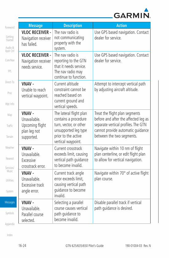
16-24 GTN 625/635/650 Pilot’s Guide 190-01004-03 Rev. N
Foreword
Getting Started
Audio & Xpdr Ctrl
Com/Nav
FPL
Direct-To
Proc
Wpt Info
Map
Traffic
Terrain
Weather
Nearest
Services/Music
Utilities
System
Messages
Symbols
Appendix
Index
Message Description Action
VLOC RECEIVER - Navigation receiver has failed.
The nav radio is not communicating property with the system.
Use GPS based navigation. Contact dealer for service.
VLOC RECEIVER - Navigation receiver needs service.
The nav radio is reporting to the GTN that it needs service. The nav radio may continue to function.
Use GPS based navigation. Contact dealer for service.
VNAV - Unable to reach vertical waypoint.
Current altitude constraint cannot be reached based on current ground and vertical speeds.
Attempt to intercept vertical path by adjusting aircraft altitude.
VNAV - Unavailable. Upcoming flight plan leg not supported.
The lateral flight plan contains a procedure turn, vector, or other unsupported leg type prior to the active vertical waypoint.
Treat the flight plan segments before and after the affected leg as separate vertical profiles. The GTN cannot provide automatic guidance between the two segments.
VNAV - Unavailable. Excessive crosstrack error.
Current crosstrack exceeds limit, causing vertical path guidance to become invalid.
Navigate within 10 nm of flight plan centerline, or edit flight plan to allow for vertical navigation.
VNAV - Unavailable. Excessive track angle error.
Current track angle error exceeds limit, causing vertical path guidance to become invalid.
Navigate within 70° of active flight plan course.
VNAV - Unavailable. Parallel course selected.
Selecting a parallel course causes vertical path guidance to become invalid.
Disable parallel track if vertical path guidance is desired.

16-25190-01004-03 Rev. N GTN 625/635/650 Pilot’s Guide
Foreword
Getting Started
Audio & Xpdr Ctrl
Com/Nav
FPL
Direct-To
Proc
Wpt Info
Map
Traffic
Terrain
Weather
Nearest
Services/Music
Utilities
System
Messages
Symbols
Appendix
Index
Message Description Action
VNAV - Unavailable. Barometric altitude lost.
A loss of data from the barometric altitude sensor causes vertical path guidance to become invalid.
Contact dealer for service.
WAYPOINT - Arriving at [wpt name].
User has configured the arrival alarm and is within the specified distance.
No action is necessary; message is informational only.
Table 16-1 Messages
Note 1: There are several reference datums that waypoints can be surveyed against. TSO-C146 normally requires that all waypoints be referenced to the WGS84 datum, but allows for navigation to waypoints that are not referenced to the WGS84 datum so long as the pilot is notified. Certain waypoints in the navigation database are not referenced to the WGS84 datum, or their reference datum is unknown. If this is the case, this message is displayed. Garmin cannot determine exactly how close the non-WGS84 referenced waypoint will be to the WGS84 datum that the GTN uses. Typically, the distance is within two nautical miles. The majority of non-WGS84 waypoints are located outside of the United States.

17-1190-01004-03 Rev. N GTN 625/635/650 Pilot’s Guide
Foreword
Getting Started
Audio & Xpdr Ctrl
Com/Nav
FPL
Direct-To
Proc
Wpt Info
Map
Traffic
Terrain
Weather
Nearest
Services/Music
Utilities
System
Messages
Symbols
Appendix
Index
17 SYMBOLSThe following tables describe the symbols that are found on the Map display.
17.1 Map Page Symbols
Symbol Description Symbol DescriptionAirport with hard surface runway(s); Non-Serviced, Primary runway shown
Airport with hard surface runway(s); Serviced, Primary runway shown
Airport with soft surface runway(s) only, Non-Serviced
Airport with soft surface runway(s) only, Serviced
Restricted (Private) Airfield Unknown Airport
Heliport NDB
Intersection Locator Outer Marker
VOR VOR/DME
VORTAC DME
TACAN TOD/BOD
User Waypoint User Airport
ATK VRP
Table 17-1 Map Page Symbols
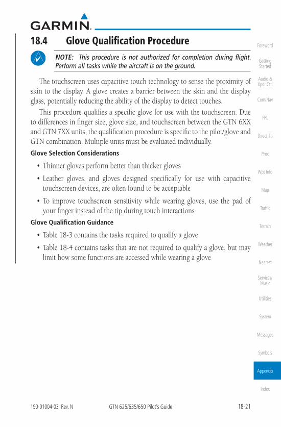
18-21190-01004-03 Rev. N GTN 625/635/650 Pilot’s Guide
Foreword
Getting Started
Audio & Xpdr Ctrl
Com/Nav
FPL
Direct-To
Proc
Wpt Info
Map
Traffic
Terrain
Weather
Nearest
Services/Music
Utilities
System
Messages
Symbols
Appendix
Index
18.4 Glove Qualification ProcedureNOTE: This procedure is not authorized for completion during flight.Perform all tasks while the aircraft is on the ground.
The touchscreen uses capacitive touch technology to sense the proximity of skin to the display. A glove creates a barrier between the skin and the display glass, potentially reducing the ability of the display to detect touches.
This procedure qualifies a specific glove for use with the touchscreen. Due to differences in finger size, glove size, and touchscreen between the GTN 6XX and GTN 7XX units, the qualification procedure is specific to the pilot/glove and GTN combination. Multiple units must be evaluated individually.
Glove Selection Considerations
• Thinner gloves perform better than thicker gloves
• Leather gloves, and gloves designed specifically for use with capacitivetouchscreen devices, are often found to be acceptable
• To improve touchscreen sensitivity while wearing gloves, use the pad ofyour finger instead of the tip during touch interactions
Glove Qualification Guidance
• Table 18-3 contains the tasks required to qualify a glove
• Table 18-4 contains tasks that are not required to qualify a glove, but maylimit how some functions are accessed while wearing a glove

18-22 GTN 625/635/650 Pilot’s Guide 190-01004-03 Rev. N
Foreword
Getting Started
Audio & Xpdr Ctrl
Com/Nav
FPL
Direct-To
Proc
Wpt Info
Map
Traffic
Terrain
Weather
Nearest
Services/Music
Utilities
System
Messages
Symbols
Appendix
Index
Glove Qualification Steps
Complete only the tasks for the capabilities relevant to the installed GTN(s).
1. Sit in the pilot’s seat.2. Start the GTN in demo mode by pressing and holding the Direct To key during
power up.3. Perform the tasks listed in Table 18-3 and Table 18-4, tapping each key with a
non-gloved finger. It is not necessary to record any results for this step.4. Repeat step 3 using a gloved hand.5. For each task, determine whether the touchscreen response is the same or worse
than without the glove.6. Record the results in the applicable table. Items that may cause the operation to be
worse include, but are not limited to:a. Multiple attempts to select a keyb. Unintentional selection of adjacent key(s)c. Excessive force on the touchscreen to select a key
7. If all applicable tasks produce the same response with and without a glove, thepilot may use the glove in flight.
Glove Qualification Procedure
Pilot:
Glove Description:
Circle the applicable GTN.
6XX 7XX
Task Operation With Glove
(circle one)
Starting from the Home page: Demo Same WorseGPS Same WorseWaypoint Same WorseType the airport identifier“KSLE.” Same WorseEnter Same WorseReturn to the Home page.

18-23190-01004-03 Rev. N GTN 625/635/650 Pilot’s Guide
Foreword
Getting Started
Audio & Xpdr Ctrl
Com/Nav
FPL
Direct-To
Proc
Wpt Info
Map
Traffic
Terrain
Weather
Nearest
Services/Music
Utilities
System
Messages
Symbols
Appendix
Index
Task Operation With Glove
(circle one)
Flight Plan Same WorseAdd Waypoint Same WorseType the airport identifier“KSLE.” Same WorseEnter Same WorseAdd each of the following waypoints in the same manner.KMMV Same WorseKONP Same WorseBTG Same WorseSelect BTG. Same WorseLoad Airway Same WorseV23 Same WorseALFOR Same WorseLoad Same WorseScroll the list of flight plan waypoints up and down using the arrow keys.
Same Worse
Back Same WorseGTN 635/650/750 onlySelect the COM STBY frequency field. Same WorseType a valid frequency. Same WorseEnter Same WorseSelect the active COM frequency field. Observe the two frequency values swap positions.
Same Worse
GTN 750 onlySelect the active NAV frequency field. Observe the two frequency values swap positions.
Same Worse
GTN 650 onlyMenu Same Worse
Table 18-3 Tests Required for Glove Qualification
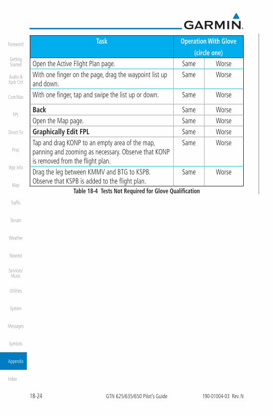
18-24 GTN 625/635/650 Pilot’s Guide 190-01004-03 Rev. N
Foreword
Getting Started
Audio & Xpdr Ctrl
Com/Nav
FPL
Direct-To
Proc
Wpt Info
Map
Traffic
Terrain
Weather
Nearest
Services/Music
Utilities
System
Messages
Symbols
Appendix
Index
Task Operation With Glove
(circle one)
Open the Active Flight Plan page. Same WorseWith one finger on the page, drag the waypoint list up and down.
Same Worse
With one finger, tap and swipe the list up or down. Same Worse
Back Same WorseOpen the Map page. Same WorseGraphically Edit FPL Same WorseTap and drag KONP to an empty area of the map, panning and zooming as necessary. Observe that KONP is removed from the flight plan.
Same Worse
Drag the leg between KMMV and BTG to KSPB. Observe that KSPB is added to the flight plan.
Same Worse
Table 18-4 Tests Not Required for Glove Qualification
