guide to deck permits - westerville
TRANSCRIPT

64 E. Walnut Street, Westerville, Ohio 43081
Guide to Deck Permits Fees
• Building Permit $75.75 (This includes a 1% State of Ohio Fee). • Zoning $40.00 • This fee is collected once a permit has been issued and is not required at the time of the application.
Application Requirements
• Completion of an application form furnished by the building department. • Two (2) sets of plans of sufficient clarity to indicate how the proposed deck will be constructed (see plan
requirements). • Two (2) survey based plot plans/site plans showing the location of the proposed deck, existing
structures, and the distances from the property/lot lines. Action on the Application
• The building and zoning departments will examine the application and plans of the proposed deck within two weeks or ten working days.
• If the application and plans of the proposed deck conform to the building and zoning codes, the applicant is notified and a deck permit is issued. The applicant shall pick up one set of the approved plans and pay the permit fees prior to the start of construction.
• If the application and plans of the proposed deck do not conform to the building and zoning codes, the applicant is notified and the reasons for the disapproval will be given in writing.
Time Limitations
• Work shall commence within twelve (12) months of the approval of the residential construction documents. One extension shall be granted for an additional twelve-month period if requested by the owner at least ten days in advance of the expiration of the approval and upon payment of a fee not to exceed one hundred dollars. If in the course of construction, work is delayed or suspended for a time period of six (6) months, the approval of the plans or drawings is invalid. Two extensions shall be granted for six months each if requested by the owner at least ten days in advance of the expiration of the approval and upon payment of a fee for each extension.
Have Questions or Need Help?
• If you have questions regarding zoning issues such as where the deck can be located, how far from the property line, and the size of the deck, please contact City Planner Tom Lodge at 614.901.6661, or City Planner Chelsea Nichols at 614.901.6662.
• If you have questions regarding building issues such as how to design or construct the deck or questions regarding the sample drawings contained in this guide, please call 614.901.6650 and ask to speak with a building inspector.

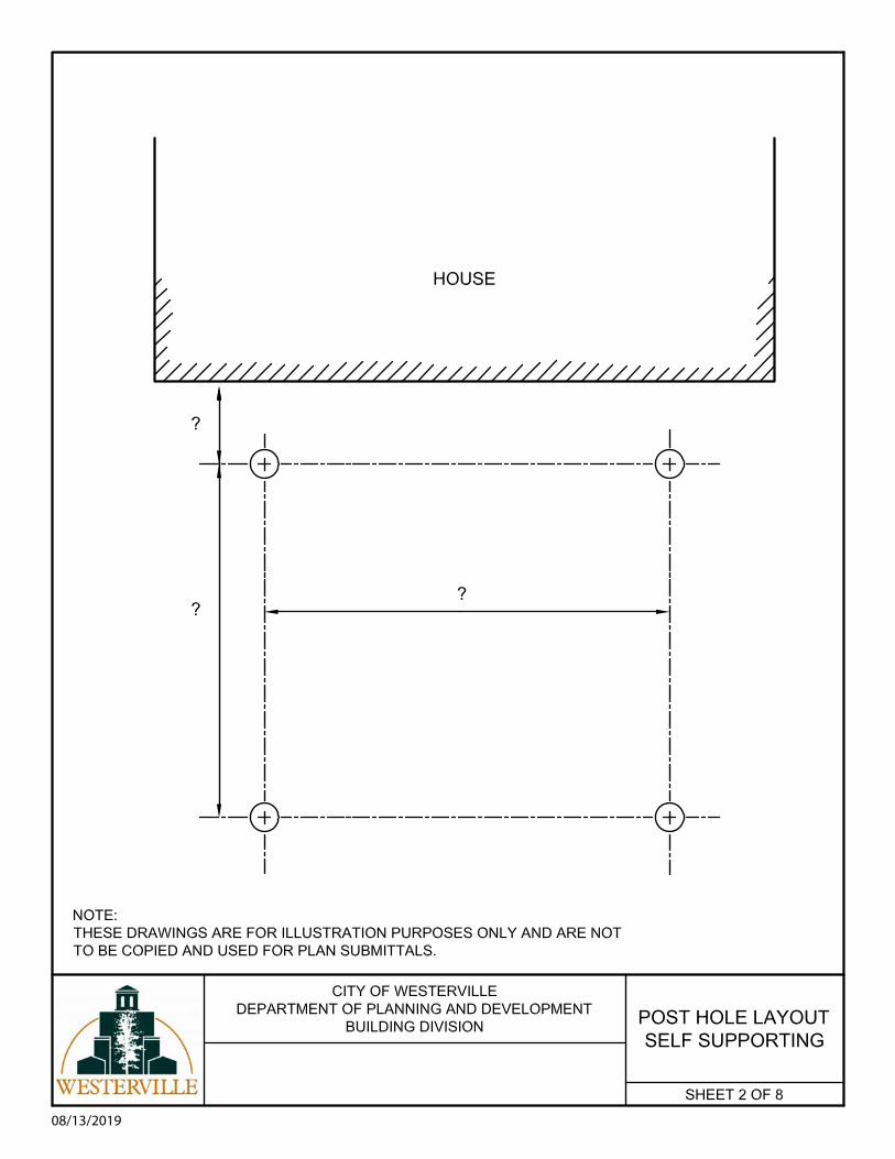
Plan Requirements Post Hole Layout – See sheet #1 for a layout of a deck that is partially supported by the house wall. Sheet #2 is a layout of a deck that is completely self-supported. The post layout shall include dimensions between each post hole and the distance between post holes and the existing dwelling. Post Hole Section – see sheet #3 for a typical post hole detail. The post hole shall be 36 inches deep and be sized according to Table 507.3.1 of the 2019 Residential Code of Ohio. The post shall bear on top of a minimum of 6 inches of concrete; the remaining portion of the post hole may be filled with gravel or dirt. If the applicant desires, they may fill the entire post hole with concrete, however the post shall bear on top of the concrete in an approved anchoring device/bracket. See figure 507.3. Framing Plan – see sheet #4 the framing plan shall include: ledger size; bolting type and method; floor joist size; span; spacing; beam(s) size and attachment method to posts; and overall deck dimensions. Refer to sheet #6 for minimum bolting requirements. Framing Sections – The framing sections shall include connections of the beam(s) to the posts. Sheet #5 shows a typical beam connection to a post. If the applicant intends on supporting one end of the floor joists using the existing dwelling, then refer to sheet #6 showing a typical ledger board section with anchorage requirements. If the applicant will be using both types of support then the plan submittal shall include framing drawings similar to sheets 5 & 6. Deck Elevation – The deck elevation shall show the height of the deck floor surface from the adjacent grade. If the deck is 30 inches or greater from the adjacent grade, a guardrail system shall be shown on the plans. Guardrails shall be 36 inches high and shall have balusters, a cable system, or horizontal rails that will not allow the passage of a 4 inch sphere. Stair Details – The plans shall show a typical stair detail. Stair risers shall have riser heights that do not exceed 8 ¼ inches. Additionally, riser heights on stairs shall not vary more than 3/8 of an inch in a stair run. Stair treads shall be a minimum of 9 inches. See sheet #8 for typical stair details. Note: four or more risers will require a continuous graspable handrail with the ends returned to the posts, and mounted between 34 & 38 inches above the stair nosing, and a graspable width of 1 1/4 inch minimum to 2 3/4 inch maximum (2019 Residential Code of Ohio Sections 311.7.8). Plans shall show the stair stringer attachment and support at the deck, and support at grade level; also, must list stringer lumber size. Inspections Footing – After the excavation of the post holes. Prior to placement of concrete and the start of the framing. Framing – Before the installation of the deck floor boards. After the installation of all structural framing members (ledger, floor joists, beams, posts). Final Inspection – After the completion of the deck. All stairs, handrails, and guardrails shall be complete. 8/13/19

LEDGER BOARD
BEAM
08/13/2019
08/13/2019

08/13/2019
For SI: 1 inch = 25.4 mm.
TABLE 507.3.1 MINIMUM FOOTING SIZE FOR DECKS
LIVE OR GROUND
SNOW LOAD b
(psf)
TRIBUTARY AREA (sq. ft.)
LOAD BEARING VALUE OF SOILS a, c, d(psf) 1500 a 2000 a 2500 a ≥3000 a
Side of a square footing
(inches)
Diameter of a round footing
(inches)
Thickness (inches)
Side of a square footing
(inches)
Diameter of a round footing
(inches)
Thickness (inches)
Side of a square footing
(inches)
Diameter of a round footing
(inches)
Thickness (inches)
Side of a square footing
(inches)
Diameter of a round footing
(inches)
Thickness (inches)
40
20 12 14 6 12 14 6 12 14 6 12 14 6 40 14 16 6 12 14 6 12 14 6 12 14 6 60 17 19 6 15 17 6 13 15 6 12 14 6 80 20 22 7 17 19 6 15 17 6 14 16 6
100 22 25 8 19 21 6 17 19 6 15 17 6 120 24 27 9 21 23 7 19 21 6 17 19 6 140 26 29 10 22 25 8 20 23 7 18 21 6 160 28 31 11 24 27 9 21 24 8 20 22 7
50
20 12 14 6 12 14 6 12 14 6 12 14 6 40 15 17 6 13 15 6 12 14 6 12 14 6 60 19 21 6 16 18 6 14 16 6 13 15 6 80 21 24 8 19 21 6 17 19 6 15 17 6 100 24 27 9 21 23 7 19 21 6 17 19 6 120 26 30 10 23 26 8 20 23 7 19 21 6 140 28 32 11 25 28 9 22 25 8 20 23 7 160 30 34 12 26 30 10 24 27 9 21 24 8
60
20 12 14 6 12 14 6 12 14 6 12 14 6 40 16 19 6 14 16 6 13 14 6 12 14 6 60 20 23 7 17 20 6 16 18 6 14 16 6 80 23 26 9 20 23 7 18 20 6 16 19 6
100 26 29 10 22 25 8 20 23 7 18 21 6 120 28 32 11 25 28 9 22 25 8 20 23 7 140 31 35 12 27 30 10 24 27 9 22 24 8 160 33 37 13 28 32 11 25 29 10 23 26 9
70
20 12 14 6 12 14 6 12 14 6 12 14 6 40 18 20 6 15 17 6 14 15 6 12 14 6 60 21 24 8 19 21 6 17 19 6 15 17 6 80 25 28 9 21 24 8 19 22 7 18 20 6
100 28 31 11 24 27 9 21 24 8 20 22 7 120 30 34 12 26 30 10 24 27 9 21 24 8 140 33 37 13 28 32 11 25 29 10 23 26 9 160 35 40 15 30 34 12 27 31 11 25 28 9
For SI: 1 inch = 25.4 mm, 1 square foot = 0.0929 m2, 1 pound per square foot = 0.0479 kPa. a. Interpolation permitted, extrapolation not permitted. b. Based on highest load case: Dead + Live or Dead + Snow. c. Assumes minimum square footing to be 12 inches x 12 inches x 6 inches for 6 x 6 post. d. If the support is a brick or CMU pier, the footing shall have a minimum 2-inch projection on all sides. e. Area, in square feet, of deck surface supported by post and footings.
NOTE: THESE DRAWINGS ARE FOR ILLUSTRATION PURPOSES ONLY AND ARE NOT TO BE COPIED AND USED FOR PLAN SUBMITTALS.

08/13/2019

08/13/2019
SHEET 5 OF 8
FRAMING PLANSELF SUPPORTED
For SI: 1 inch = 25.4 mm.
FIGURE 507.5.1(1) DECK BEAM TO DECK POST
For SI: 1 inch = 25.4 mm.
FIGURE 507.5.1(2) NOTCHED POST-TO-BEAM CONNECTION

08/13/2019
SHEET 6 OF 8
FRAMING SECTION
TABLE 507.9.1.3(1) DECK LEDGER CONNECTION TO BAND JOIST a, b
(Deck live load = 40 psf, deck dead load = 10 psf, snow load ≤ 40 psf)
CONNECTION DETAILS
JOIST SPAN
6′ and less 6′ 1″ to 8′ 8′ 1″ to 10′ 10′ 1″ to 12′ 12′ 1″ to 14′ 14′ 1″ to 16′ 16′ 1″ to 18′
On-center spacing of fasteners 1/2 -inch diameter lag screw with 1/2 -inch
maximum sheathing c, d 30 23 18 15 13 11 10
1/2 -inch diameter bolt with 1/2 -inch maximum sheathing d 36 36 34 29 24 21 19
1/2 -inch diameter bolt with 1-inch maximum sheathing e 36 36 29 24 21 18 16
For SI: 1 inch = 25.4 mm, 1 foot = 304.8 mm, 1 pound per square foot = 0.0479 kPa. a. Ledgers shall be flashed in accordance with Section 703.4 to prevent water from contacting the house band joist. b. Snow load shall not be assumed to act concurrently with live load. c. The tip of the lag screw shall fully extend beyond the inside face of the band joist. d. Sheathing shall be wood structural panel or solid sawn lumber. e. Sheathing shall be permitted to be wood structural panel, gypsum board, fiberboard, lumber or foam sheathing. Up to 1/2 -inch thickness
of stacked washers shall be permitted to substitute for up to 1/2 -inch of allowable sheathing thickness where combined with wood structural panel or lumber sheathing.
TABLE 507.9.1.3(2)
PLACEMENT OF LAG SCREWS AND BOLTS IN DECK LEDGERS AND BAND JOISTS
MINIMUM END AND EDGE DISTANCES AND SPACING TOP EDGE BOTTOM EDGE ENDS ROW SPACING Ledger a 2 inches 3/4 -inch 2 inches 15/8 inches b
Band Joist c 3/4 -inch 2 inches 2 inches b 15/8 inches b
For SI: 1 inch = 25.4 mm. a. Lag screws or bolts shall be staggered from the top to the bottom along the horizontal run of the deck ledger
in accordance with Figure 507.9.1.3(1). b. Maximum 5 inches. c. For engineered rim joists, the manufacturer’s recommendations shall govern. d. The minimum distance from bottom row of lag screws or bolts to the top edge of the ledger shall be in
accordance with Figure 507.9.1.3(1).
For SI: 1 inch = 25.4 mm.

08/13/2019
SHEET 7 OF 8
DECKELEVATION

08/13/2019
SHEET 8 OF 8
STAIRDETAIL