h-1 performance of an electro-hydraulic active steering system · performance of an...
TRANSCRIPT

Performance of an electro-hydraulic active steering system
Dipl.-Ing. Eric Fischer Institut für Fluidtechnik (IFD), Technische Universität Dresden, Helmholtzstrasse 7a, 01069 Dresden, E-mail: [email protected]
Dipl.-Ing. André Sitte Institut für Fluidtechnik (IFD), Technische Universität Dresden, Helmholtzstrasse 7a, 01069 Dresden, E-mail: [email protected]
Professor Dr.-Ing. Jürgen Weber Institut für Fluidtechnik (IFD), Technische Universität Dresden, Helmholtzstrasse 7a, 01069 Dresden, E-mail: [email protected]
Dr.-Ing Erhard Bergmann Hydraulik Nord Fluidtechnik GmbH & Co.KG, Ludwigsluster Chaussee 5 19370 Parchim, E-Mail: [email protected]
Dipl.-Ing. Markus de la Motte Hydraulik Nord Fluidtechnik GmbH & Co.KG, Ludwigsluster Chaussee 5 19370 Parchim, E-Mail: [email protected]
Abstract Hydrostatic steering systems are used in construction and agricultural machines alike.
Because of their high power density, hydraulic drives are qualified for the use in vehicles
with high steering loads. Conventional hydrostatic steering systems are limited in terms
of steering comfort and driver assistance. For realisation of appropriate steering
functions, electro-hydraulic solutions are necessary. This paper provides an overview on
existing implementations and introduces a novel steering system. The presented active
steering system with independent meter-in and meter-out valves fills the gap between
existing active steering systems and steer-by-wire solutions. An appropriate control and
safety concept provides advanced steering functions for on-road usage without the fully
redundant structure of steer-by-wire systems.
KEYWORDS: active steering system, steering function, functional safety, test vehicle
1. Overview and system introduction Hydrostatic steering systems of various designs are used in construction and agricultural
machines alike. The increasing complexity of workflows requires driver-assisted steering
Group H - Mobile Hydraulics | Paper H-1 375
or even an automation of steering-functions. Therefore electronically controlled
components are necessary, which could be integrated to the steering system in several
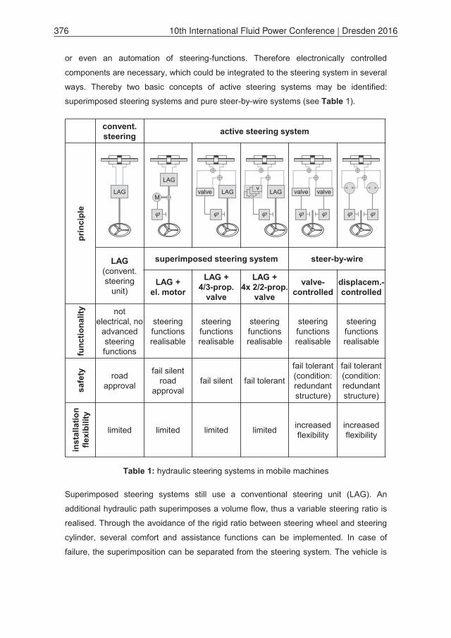
ways. Thereby two basic concepts of active steering systems may be identified:
superimposed steering systems and pure steer-by-wire systems (see Table 1).
Table 1: hydraulic steering systems in mobile machines
Superimposed steering systems still use a conventional steering unit (LAG). An
additional hydraulic path superimposes a volume flow, thus a variable steering ratio is
realised. Through the avoidance of the rigid ratio between steering wheel and steering
cylinder, several comfort and assistance functions can be implemented. In case of
failure, the superimposition can be separated from the steering system. The vehicle is
convent. steering active steering system
prin
cipl
e
LAG (convent. steering
unit)
superimposed steering system steer-by-wire
LAG + el. motor
LAG +4/3-prop.
valve
LAG + 4x 2/2-prop.
valve
valve-controlled
displacem.-controlled
func
tiona
lity not
electrical, no advancedsteering functions
steering functions realisable
steering functions realisable
steering functions realisable
steering functions realisable
steering functions realisable
safe
ty roadapproval
fail silentroad
approvalfail silent fail tolerant
fail tolerant(condition: redundantstructure)
fail tolerant (condition: redundantstructure)
inst
alla
tion
flexi
bilit
y
limited limited limited limited increased flexibility
increased flexibility
valve valveLAG valve LAG LAGvvvvLAG
M
376 10th International Fluid Power Conference | Dresden 2016

still manoeuvrable, through the conventional hydrostatic steering unit. Furthermore, the
properties of emergency steering are preserved.
One possibility to realise a superimposed steering system is to mount a summation
gearbox at the steering linkage. The rotational speed of the steering wheel and of an
additional electric motor are added at the planetary gear. Therefore, the rotational
speeds influence the conveyed volume flow of the steering unit. An electronic control unit
(ECU), dependent on driver input and the implemented steering functions, controls the
electric motor. Comparable implementations are applied in automotive industry /1/. In
case the steering volume flow is to be superimposed instead of rotational speed,
electrohydraulic proportional valves can be used in addition to the steering unit. The
control of the valve is realised by means of different sensor signals. An available active
steering system is the OSPE from Danfoss Power Solutions /2/. In case of on-road use,
the electrohydraulic valve section must be deactivated, because failures in the electro-
hydraulic part cause safety-critical states and a time-critical deactivation is necessary.
Then steering is possible using the conventional steering unit.
If the mechanical linkage between steering wheel and steering valve is completely
eliminated, the system is called steer-by-wire system (SBW-system). This solution is
done without a hydraulic-mechanical backup. An ECU processes the sensor data and
generates actuating values. Two different structures can be found:
The first one is a displacement-controlled system comparable to /3/ or /4/.The second
approach are valve-controlled steer-by-wire systems, based on electrohydraulic
proportional valves. Such concepts are presented in /5/ or in /6/. For a roadworthy SBW-
system an extensive safety concept and an entirely redundant structure is necessary to
avoid a dangerous machine behaviour in case of failure. Steer-by-wire systems without
redundancy are usually equipped with a superimposed, prioritised conventional
hydrostatic steering unit. In case of high velocities and on-road use, the conventional
system is activated. The utilisation of the electrohydraulic steering is permitted only at
lower speeds. The structure layout corresponds to the superimposed steering system,
but the hydrostatic and electrohydraulic steering are not active at the same time. There
is no superposition of volume flow (/7/, /8/).
The proposed approach to implement an electrohydraulic active steering system is the
realisation of a superposed valve structure with independent meter-in and meter-out
valves (see Figure 1). One main advantage is use qualification for on-road applications
without the entirely redundant implementation of SBW-systems. Appropriate valve
control strategies open this opportunity, because it is possible to compensate single
Group H - Mobile Hydraulics | Paper H-1 377
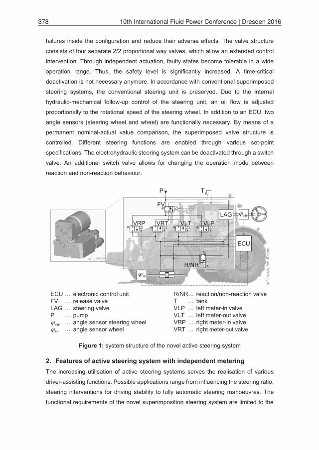
failures inside the configuration and reduce their adverse effects. The valve structure
consists of four separate 2/2 proportional way valves, which allow an extended control
intervention. Through independent actuation, faulty states become tolerable in a wide
operation range. Thus, the safety level is significantly increased. A time-critical
deactivation is not necessary anymore. In accordance with conventional superimposed
steering systems, the conventional steering unit is preserved. Due to the internal
hydraulic-mechanical follow-up control of the steering unit, an oil flow is adjusted
proportionally to the rotational speed of the steering wheel. In addition to an ECU, two
angle sensors (steering wheel and wheel) are functionally necessary. By means of a
permanent nominal-actual value comparison, the superimposed valve structure is
controlled. Different steering functions are enabled through various set-point
specifications. The electrohydraulic steering system can be deactivated through a switch
valve. An additional switch valve allows for changing the operation mode between
reaction and non-reaction behaviour.
Figure 1: system structure of the novel active steering system
2. Features of active steering system with independent metering The increasing utilisation of active steering systems serves the realisation of various
driver-assisting functions. Possible applications range from influencing the steering ratio,
steering interventions for driving stability to fully automatic steering manoeuvres. The
functional requirements of the novel superimposition steering system are limited to the
P T
VRP VRT VLP
FV
VLTLAG
ECU
R/NR
R/NRTVLPVLTVRPVRT
………………
reaction/non-reaction valvetankleft meter-in valveleft meter-out valveright meter-in valveright meter-out valve
ECUFVLAGP
………………
electronic control unitrelease valvesteering valvepumpangle sensor steering wheelangle sensor wheel
ref.: HNF
ref.:
ww
w.fe
ndt.c
om
378 10th International Fluid Power Conference | Dresden 2016
two aspects mentioned first. However, automatic steering functions can be realised as
well with the introduced system. Precondition is the availability of appropriate sensor
signals and corresponding control values.
The steering functions listed below are implemented:
Directional stability and leakage compensation
Variable steering ratio
Defined centre position of steering wheel („12 o´clock position”)
Ability to switch between reaction and non-reaction behaviour
In purely hydrostatic steering systems, high external loads result in a slight displacement
of the steering cylinder due to leakage, although no steering is intended. This results in
a continuous correction of the vehicle´s trajectory by the driver on inclined lanes. The
implementation of a leakage compensation enables the directional stability of the
machine.
In order to adjust the needed steering effort to different driving situations it is necessary
to adapt the steering ratio. This is realised by means of several constant steering ratios
for each driving range and mode or by a variable steering ratio, which continuously
adapts to the driving state. The implemented variable steering ratio depends on the
vehicle´s speed. Thus, a good directional stability at high velocities and comfortable
handling for slow driving is possible.
In agricultural and construction machines, usually there is no defined neutral position of
the steering wheel. This is due to the already mentioned leakage in conventional steering
units or to a variable steering ratio depending on the driving state. Therefore, the steering
wheel of such vehicles cannot be equipped with several control elements, as it is the
case in commercial vehicles and passenger cars. An integration of various control
elements would offer new possibilities in cabin design an increases the ease of
operation.
By the use of fully automatic driving functions, the vehicle performs a defined steering
motion without any driver-induced steering wheel rotation. During autonomous driving
manoeuvres, there should be no noticeable reactions at the steering wheel. Therefore,
a non-reaction behaviour of the conventional steering unit is required. Additionally, there
is sometimes a demand for automotive driving experience. This includes noticeable
steering forces at the steering wheel and wheels, which lead to automatic centring of the
Group H - Mobile Hydraulics | Paper H-1 379
wheels. To satisfy those opposing requirements a changeable operating state is
necessary.
3. Development and realisation of the active steering system The design, implementation and testing of the active steering system with independent
valves and the implemented steering functions was conducted in a multi stage
development process. In the first step, the novel steering system was analysed in a
system simulation. The built simulation model based on (1) a complex, physical model
of the steering system, (2) the machine periphery and (3) the surrounding process
conditions. Due to the detailed modelling, verifiable and application-specific statements
can be derived.
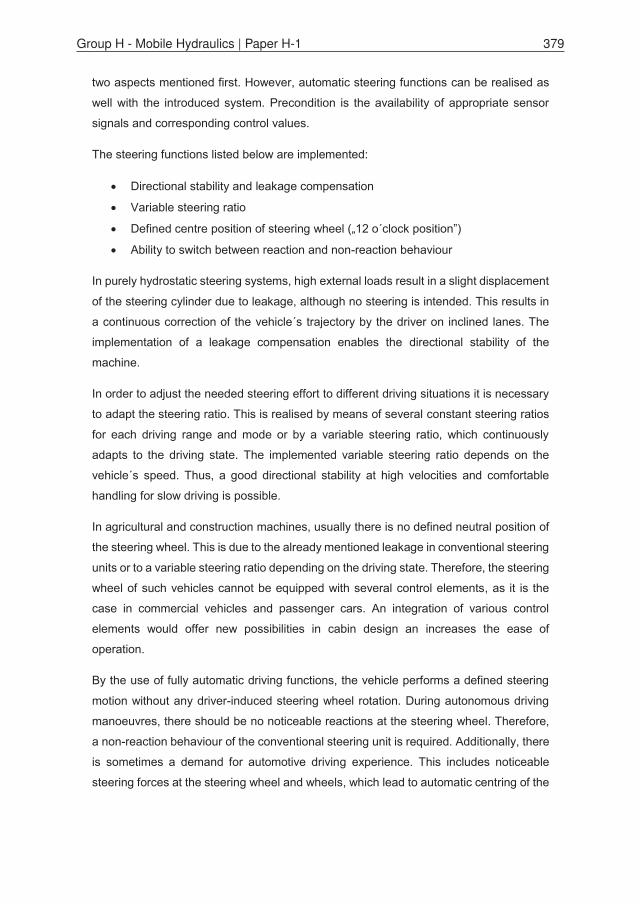
Besides the simulative considerations, a test rig was built at the IFD (Institute for Fluid
Power Dresden). Realistic testing conditions are achieved by integrating the steering
system into the actual hydraulic and mechanical machine periphery. Therefore, the
whole steerable front axle of the vehicle and the hydraulic steering circuit were
implemented at the test rig. Furthermore, an electro-hydraulic cylinder drive generates
operating point dependent loads. Various calculation models and presettings are
available for a provided load set-point. The test rig´s control as well as the acquisition of
measured data is done by an integral monitoring and control system. The test rig is
shown in Figure 2.
Figure 2: steering system test rig at the IFD
user input
ECU steeringsystem
control andmeasuring system
pressure oil flow force valve ctrl.
valv
ect
rl.an
gle
user i
380 10th International Fluid Power Conference | Dresden 2016
Additionally to the test rig, the steering system was implemented into a demonstrator
vehicle (Fendt 927 Vario) for testing the system and the steering functions under realistic
operating conditions.
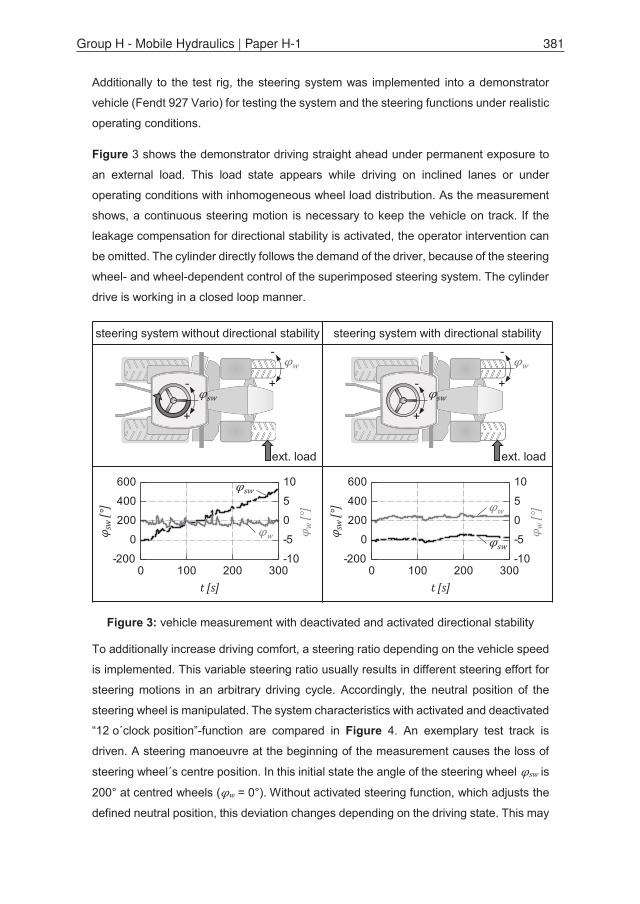
Figure 3 shows the demonstrator driving straight ahead under permanent exposure to
an external load. This load state appears while driving on inclined lanes or under
operating conditions with inhomogeneous wheel load distribution. As the measurement
shows, a continuous steering motion is necessary to keep the vehicle on track. If the
leakage compensation for directional stability is activated, the operator intervention can
be omitted. The cylinder directly follows the demand of the driver, because of the steering
wheel- and wheel-dependent control of the superimposed steering system. The cylinder
drive is working in a closed loop manner.
Figure 3: vehicle measurement with deactivated and activated directional stability
To additionally increase driving comfort, a steering ratio depending on the vehicle speed
is implemented. This variable steering ratio usually results in different steering effort for
steering motions in an arbitrary driving cycle. Accordingly, the neutral position of the
steering wheel is manipulated. The system characteristics with activated and deactivated
“12 o´clock position”-function are compared in Figure 4. An exemplary test track is
driven. A steering manoeuvre at the beginning of the measurement causes the loss of
steering wheel´s centre position. In this initial state the angle of the steering wheel is
200° at centred wheels ( = 0°). Without activated steering function, which adjusts the
defined neutral position, this deviation changes depending on the driving state. This may
0 100 200 300t [s]
0
5
10
-5
-10
φ w [°
]0
200
400
600
-200
φ sw
[°]
0 100 200 300t [s]
0
5
10
-5
-10
φ w [°
]
0
200
400
600
-200
φ sw
[°]
steering system without directional stability steering system with directional stability
ext. load
-
+
-
+
ext. load
-
+
-
+
Group H - Mobile Hydraulics | Paper H-1 381
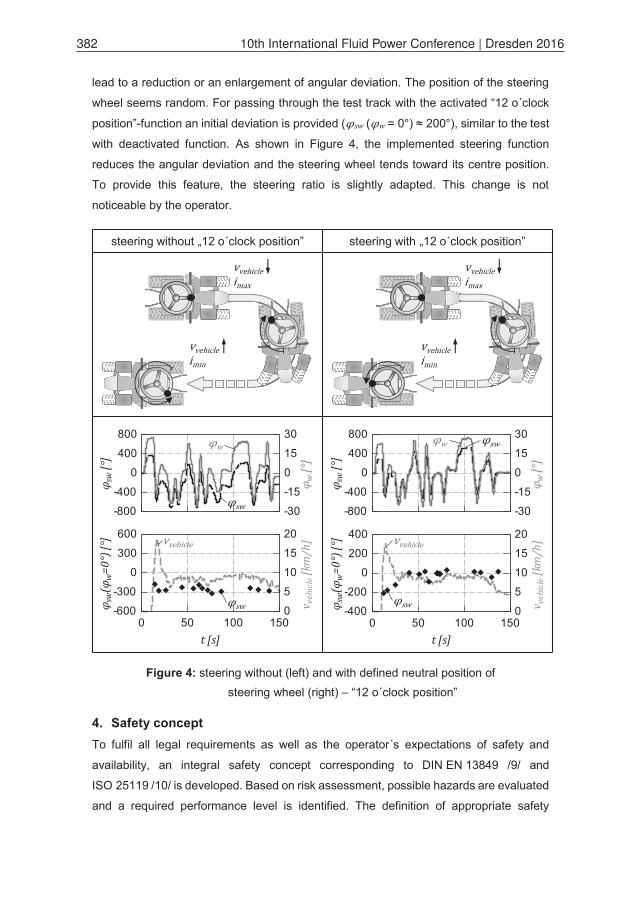
lead to a reduction or an enlargement of angular deviation. The position of the steering
wheel seems random. For passing through the test track with the activated “12 o´clock
position”-function an initial deviation is provided ( ( = 0°) ≈ 200°), similar to the test
with deactivated function. As shown in Figure 4, the implemented steering function
reduces the angular deviation and the steering wheel tends toward its centre position.
To provide this feature, the steering ratio is slightly adapted. This change is not
noticeable by the operator.
Figure 4: steering without (left) and with defined neutral position of steering wheel (right) – “12 o´clock position”
4. Safety concept To fulfil all legal requirements as well as the operator´s expectations of safety and
availability, an integral safety concept corresponding to DIN EN 13849 /9/ and
ISO 25119 /10/ is developed. Based on risk assessment, possible hazards are evaluated
and a required performance level is identified. The definition of appropriate safety
0
15
30
-15
-30
φ w [°
]
0
400
800
-400
-800
φ sw
[°]
0
15
30
-15
-30
φ w [°
]
0
400
800
-400
-800
φ sw
[°]
steering without „12 o´clock position” steering with „12 o´clock position”
0 50 100 150t [s]
0
200
400
-200
-400φ sw
(φw
=0°)
[°]
0
5
10
15
20v v
ehic
le [k
m/h
]
0 50 100 150t [s]
0
300
600
-300
-600φ sw
(φw
=0°)
[°]
0
5
10
15
20
v veh
icle
[km
/h]
382 10th International Fluid Power Conference | Dresden 2016

functions serves the reduction of emerging risks by maintaining a safe state or by taking
measures to pass over to a safe state in case of failure. Because mobile machines are
operator-controlled and their operating scenarios are subject to significant variations,
there are many safety-relevant operational states. A comprehensive failure simulation,
adopted from the introduced simulation model, allows for the reproduction of all basic
conditions. With failure simulation, it is possible to analyse possible failures and their
effects on the entire steering system as well as vehicle behaviour. The simulation is
comparable to an FMEA (failure mode and effect analysis) and helps to identify critical
components relevant for the safety function. Notably, the electrical and electronical
components of the steering system are in the focus of attention, because they cannot be
designed fatigue endurable like mechanical parts and show a stochastic failure
behaviour. Additionally valve and sensor errors are considered. In order to derive
universal statements relating to failure effects, all relevant operating states like pulling
and resistive loads are considered. Thus, there is a significant number of faulty system
states.
With the help of a simulation-based identification of safety-critical components, a safety-
related block diagram can be derived for the safety function. The block diagram illustrates
the structural composition of the safety function and provides the basis for the calculation
of the present safety level /11/.
For the development of safety concept of the steering system, a merely simulative
consideration is insufficient. Especially for complex, safety relevant systems test rig trials
and field tests are indispensable. Thus, it is necessary to investigate the system
behaviour in case of a single failure at the test rig and at the demonstrator vehicle to
validate the safety concept. The considered faulty states correspond to errors reviewed
in the failure simulation. Testing the safety concept at the demonstrator represents the
highest level of validation, because the outcome is not influenced by model-based
simplifications or by limits related to the test rig. Faulty states are forced by the electronic
control device. An excerpt of the executed error analysis is shown in Figure 5.
The figure illustrates the behaviour of a conventional and the novel superimposition
steering system in a case of failure. In a conventional active steering system, an
accidentally opened valve leads to a dangerous movement during straight ahead drive,
because of a faulty volume flow to the steering cylinder. The driver is not able to
compensate the failure effect ( ≈ 150 mm). The superimposed steering system must
be switched off time-critically to preserve manoeuvrability. If a comparable single error
occurs in a system with independent metering, safety critical states will not appear. By
Group H - Mobile Hydraulics | Paper H-1 383
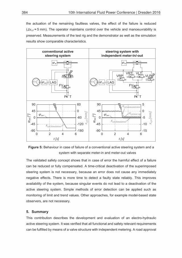
the actuation of the remaining faultless valves, the effect of the failure is reduced
( ≈ 5 mm). The operator maintains control over the vehicle and manoeuvrability is
preserved. Measurements of the test rig and the demonstrator as well as the simulation
results show comparable characteristics.
Figure 5: Behaviour in case of failure of a conventional active steering system and a system with separate meter-in and meter-out valves
The validated safety concept shows that in case of error the harmful effect of a failure
can be reduced or fully compensated. A time-critical deactivation of the superimposed
steering system is not necessary, because an error does not cause any immediately
negative effects. There is more time to detect a faulty state reliably. This improves
availability of the system, because singular events do not lead to a deactivation of the
active steering system. Simple methods of error detection can be applied such as
monitoring of limit and trend values. Other approaches, for example model-based state
observers, are not necessary.
5. Summary This contribution describes the development and evaluation of an electro-hydraulic
active steering system. It was verified that all functional and safety relevant requirements
can be fulfilled by means of a valve structure with independent metering. A road approval
conventional activesteering system
steering system withindependent meter-in/-out
P T
VRPVRT
VLP
FV
VLT
LAG
P T
FVLAG
0 2 4 6t [s]
0
5
-5
-10
-15
x cyl
[mm
]
0
45
90
-45
-90
φ sw
[°]
0 2 4 6t [s]
0
60
-60
-120
-180
x cyl
[mm
]
0
45
90
-45
-90
φ sw
[°]
384 10th International Fluid Power Conference | Dresden 2016

for the steering system is possible, because faulty states in the steering system do not
affect the machines safety and the vehicle´s manoeuvrability is preserved. The
introduced system reaches a high safety level without using a fully redundant structure.
Thus, the system is able to close the gap between existing superimposed steering
systems and steer-by-wire solutions. Based on extensive simulations and experimental
evaluation, potentials and limits of the analysed concept can be shown.
6. Acknowledgement
The European Union supports this research and development project with funds from
the European Regional Development Fund (ERDF).
7. References /1/ Pfeffer, Peter; Harrer, Manfred. Lenkungshandbuch. Lenksysteme, Lenkgefühl,
Fahrdynamik von Kraftfahrzeugen. Vieweg + Teubner Verlag, Wiesbaden, 2011
/2/ N.N. Danfoss – Technical Information. Steering. OSPE Steering Valve. SASA
Sensor. Danfoss A/S, 2015
/3/ Daher, Naseem; Ivantysynova, Monika. New Steering Concept for Wheel
Loaders. 9th International Fluid Power Conference, Aachen, Germany, pp. 224–
235, March 24-26, 2014
/4/ N.N. Weber-Hydraulik GmbH – Agrartechnische Lösungen au seiner Hand.
O+P. Fluidtechnik für den Maschinen- und Anlagenbau. Nov./Dez. 2015,
pp. 22-23, Vereinigte Fachverlage GmbH, Mainz, 2015
/5/ Schmitz, David. Entwurf eines fehlertoleranten Lenkventils für Steer-by-Wire
Anwendungen bei Traktoren. Karlsruher Schriftenreihe Fahrzeugsystem-
technik. Band 26, Dissertation, Karlsruhe, 2014
/6/ N.N. Exklusiver Fahrbericht John Deere 8360R: Stärkste 8R-Bahn der Welt.
Profi. Magazin für professionelle Agrartechnik. Sonderdruck aus 1/2011.
Landwirtschaftsverlag GmbH, Münster 2011
Group H - Mobile Hydraulics | Paper H-1 385
/7/ Galler, Daniel. Im Joystick-Fieber. Konstruktionspraxis. January 2013, pp. 64-
65, Vogel Business Media GmbH & Co. KG, Würzburg, 2013
/8/ N.N. HYDAC International – HY-STEER. Elektro-hydraulische Lenksysteme.
HYDAC International GmbH, April 2015
/9/ N.N., DIN EN ISO 13849 Sicherheit von Maschinen – Sicherheitsbezogene
Teile der Steuerung, 2008
/10/ N.N., ISO 25119, Tractors and machinery for agriculture and forestry – Safety-
related parts of control systems, 2010
/11/ Fischer, Eric; Sitte, André; Weber, Jürgen; Bergmann, Erhard; de la Motte,
Markus. Safety Related Development of an Electro-Hydraulic Active Steering
System. 18th ITI Symposium, Dresden, Germany, pp. 263-270, November 9-
11, 2015
8. Nomenclature
Maximum ratio -
Minimum ratio -
Time s
Velocity of the vehicle km/h
Position of the steering cylinder mm
Displacement of the steering cylinder mm
Angle °
Angle of the steering wheel °
Angle of the vehicle´s wheel °
386 10th International Fluid Power Conference | Dresden 2016