hall effect transducers series: t series: tm · issued by: u.t. date: 18/10/2017 rev.: 00 approved...
TRANSCRIPT

ISSUED BY: U.T. DATE: 18/10/2017 REV.: 00 APPROVED BY: W. COTTARELLI
HALL EFFECT TRANSDUCERS
SERIES: T SERIES: TM
DESCRIZIONE
The T and TM series transducers find their optimal use in the following applications:
• Heating system HAVC
• Conditioning systems HAVC
• Boiler systems (steam)
• Industrial applications
Consisting of a Hall sensor, the development of this transducer is based on the concept of the solicitation of a semiconductor by means of a magnet. The stainless steel sensitive element moves perpendicularly a magnet placed near the Hall sensor generating a potential difference on the opposite face of the semiconductor. By means of this effect an electrical signal is obtained which is proportional to the applied pressure. The TM series transductor is a variant of the T series with the addition of a pressure gauge that allows the display of the pressure even in the absence of power supply. It is made of reinforced technopolymer in such a way as to withstand mechanical stresses and high thermodynamic conditions. The use of ultrasonic welding technology makes the coupling of the components making up the product homogeneous and stable over time, avoiding metal joints or rivets.

ISSUED BY: U.T. DATE: 18/10/2017 REV.: 00 APPROVED BY: W. COTTARELLI
CONSTRUCTION FEATURES
Plastic casing Polyarylamide Solvay (also avalilable as IEC 60695-2-12 GWFI approved materials)
Sensitive component AISI
Seal EPDM; NBR; FPM; SILICONE
Sensor Programmabile
Connector RAST 2,5 (AMP duoplug type)
Protection degree IP00
Weight 22 gr.
OPERATIONAL FEATURES
Operating range 0÷3 bar 0÷4 bar 0÷6 bar
Overload pressure ≤10 bar
Breakdown pressure >20 bar
Fluid temperature ≤ 80°C; ≤110°C (thermal shock max. 3 minutes)
Ambient temperature ≤90°C
Fluid Liquid, gas or water containing the usual concentrations and additives for heating circuits and glycols.
Manometer Displays 0-3 bar (only on TM series)
ELECTRICAL FEATURES
Supply 5 Vdc (±3%); 8-30 Vdc
Output signal (Customisation feasible) 0÷3 bar
0…3 Vdc
0÷4 bar
0,5...2,5 Vdc; 0,5...3,5 Vdc
0÷6 bar
0,5...4,3 Vdc
Electrical absorption <9mA
Resistance load ≥4,7 KΩ
Capacitance load 10nF
APPROVALS
EN61000-4-2, EN61000-4-3, EN61000-4-4 All our products conform to the 2002/95/EC European directive (RoHS)

ISSUED BY: U.T. DATE: 18/10/2017 REV.: 00 APPROVED BY: W. COTTARELLI
TRANSDUCER FUNCTIONAL CURVE
PRESSURE RANGE: 0,0 – 3,0 bar; OUTPUT SIGNAL: 0,0 – 3,0 VDC
TRANSDUCER FUNCTIONAL CURVE 0,0 – 3,0 bar
(DETAILED VIEW OF THE PREVIOUS CURVE; PRESSURE RANGE: 0,0 – 1,0 bar)
ISSUED BY: U.T. DATE: 18/10/2017 REV.: 00 APPROVED BY: W. COTTARELLI
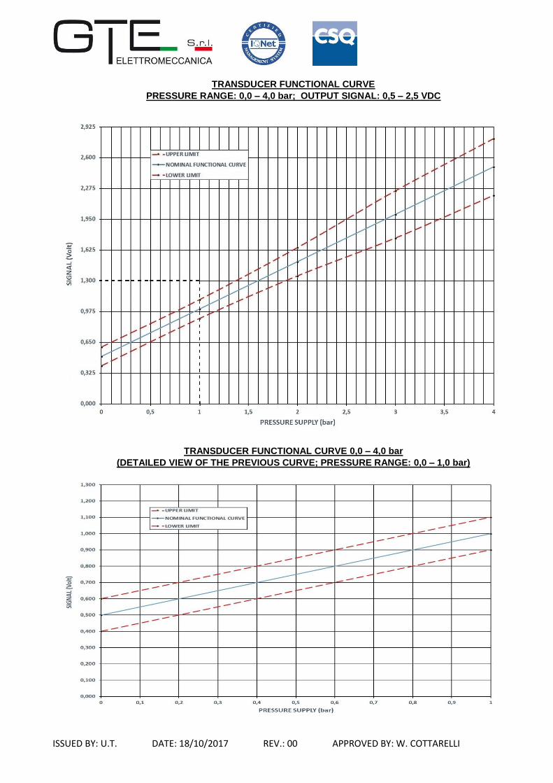
TRANSDUCER FUNCTIONAL CURVE
PRESSURE RANGE: 0,0 – 4,0 bar; OUTPUT SIGNAL: 0,5 – 2,5 VDC
TRANSDUCER FUNCTIONAL CURVE 0,0 – 4,0 bar
(DETAILED VIEW OF THE PREVIOUS CURVE; PRESSURE RANGE: 0,0 – 1,0 bar)

ISSUED BY: U.T. DATE: 18/10/2017 REV.: 00 APPROVED BY: W. COTTARELLI
TRANSDUCER FUNCTIONAL CURVE
PRESSURE RANGE: 0,0 – 4,0 bar; OUTPUT SIGNAL: 0,5 – 3,5 VDC
TRANSDUCER FUNCTIONAL CURVE 0,0 – 4,0 bar
(DETAILED VIEW OF THE PREVIOUS CURVE; PRESSURE RANGE: 0,0 – 1,0 bar)

ISSUED BY: U.T. DATE: 18/10/2017 REV.: 00 APPROVED BY: W. COTTARELLI
TRANSDUCER FUNCTIONAL CURVE
PRESSURE RANGE: 0,0 – 6,0 bar; OUTPUT SIGNAL: 0,5 – 4,3 VDC
TRANSDUCER FUNCTIONAL CURVE 0,0 – 6,0 bar
(DETAILED VIEW OF THE PREVIOUS CURVE; PRESSURE RANGE: 0,0 – 2,5 bar)
TRANSDUCER FUNCTIONAL CURVE 0,0 – 6,0 bar
(DETAILED VIEW OF THE UPPER CURVE; PRESSURE RANGE: 4,0 – 6,0 bar)

ISSUED BY: U.T. DATE: 18/10/2017 REV.: 00 APPROVED BY: W. COTTARELLI
ELECTRICAL CONNECTIONS DIMENSIONAL PATTERNS