hardware synthesis based on rassp education & facilitation program and prof. p. p. chu “rtl...
Post on 19-Dec-2015
216 views
TRANSCRIPT
Hardware SynthesisHardware Synthesis
Based on
RASSP Education & Facilitation Program and
Prof. P. P. Chu “RTL Hardware Design Using VHDL”

Definition
Hardware synthesis:Hardware synthesis:
The process of The process of producing aproducing a control sequence and control sequence and logical structurelogical structure that will implement a given that will implement a given abstract behavior satisfying a given set of abstract behavior satisfying a given set of constraints (e.g., I/O rates, MIPS, sample period) constraints (e.g., I/O rates, MIPS, sample period) while trying to improve upon a set of objective while trying to improve upon a set of objective metrics (e.g., area, speed, power dissipation) of a metrics (e.g., area, speed, power dissipation) of a design. design.
Synthesis to the gate-level of abstraction consistsSynthesis to the gate-level of abstraction consists of three of three major steps -major steps -
Design specification (in a machine-readable form)Design specification (in a machine-readable form)
Design implementationDesign implementation
Design validation and verificationDesign validation and verification
Design specification implies a description of the design Design specification implies a description of the design where functional, performance, and cost constraints (area, where functional, performance, and cost constraints (area, power, speed) are captured in a form that is executable in a power, speed) are captured in a form that is executable in a CAD environment. CAD environment.
Two common methods for capturing the specification are:Two common methods for capturing the specification are:Graphical methodsGraphical methods
Language-based methodsLanguage-based methods
Steps in the Synthesis ProcessSteps in the Synthesis Process
Graphical MethodsGraphical Methods
Graphical methods include:Graphical methods include:Block diagrams, state diagrams, schematics, data flow graphs, Block diagrams, state diagrams, schematics, data flow graphs, timing diagrams, truth tables, etc.timing diagrams, truth tables, etc.
Advantages: Advantages: Faster learning curve,Faster learning curve,Intuitive documentation, andIntuitive documentation, andReusability of design.Reusability of design.
Disadvantages: Disadvantages: Limited support for functional and timing hierarchy in complex Limited support for functional and timing hierarchy in complex digital systemsdigital systemsLimited support for multiple views (e.g., simulation versus Limited support for multiple views (e.g., simulation versus hardware generation).hardware generation).
Language-based MethodsLanguage-based Methods
Language based methods include:Language based methods include:Hardware description languages (HDLs), high level Hardware description languages (HDLs), high level algorithmic macro descriptors (such as Matlab), or algorithmic macro descriptors (such as Matlab), or application-specific languages (such as Silage and DSP/C application-specific languages (such as Silage and DSP/C for signal processing).for signal processing).
Advantages: Advantages: Ability to serve as a standard medium of communication Ability to serve as a standard medium of communication between the algorithm developer and the synthesis expertbetween the algorithm developer and the synthesis expertRobustness through well-defined semanticsRobustness through well-defined semanticsAbility for representing complex behavior and data Ability for representing complex behavior and data structuresstructures

Language-based Methods (Cont.)Language-based Methods (Cont.)
Support for synthesis and its verification in the Support for synthesis and its verification in the same environment,same environment,
Their system-independent nature that facilitates Their system-independent nature that facilitates design documentation.design documentation.
Disadvantages:Disadvantages:Specification is harder to visualize, and requires Specification is harder to visualize, and requires a longer learning curve.a longer learning curve.

Steps in the Synthesis Process (Cont.)Steps in the Synthesis Process (Cont.)
Design ImplementationDesign Implementation consists of a number consists of a number of intermediate steps: of intermediate steps:
Algorithm design:Algorithm design:Evaluates the performance of the implemented Evaluates the performance of the implemented algorithm in terms of:algorithm in terms of:
The precision of the word length,The precision of the word length,The number of iterations, andThe number of iterations, andThe quality of the results obtained with respect to the The quality of the results obtained with respect to the design requirements.design requirements.
Behavioral simulations:Behavioral simulations:Done after the algorithm design is complete to verify Done after the algorithm design is complete to verify the detailed functional behavior of the system.the detailed functional behavior of the system.

Steps in theSynthesis Process (Cont.)Steps in theSynthesis Process (Cont.)
Data and control flow graph generation:Data and control flow graph generation:Module selection Module selection
determining which modules are used in designdetermining which modules are used in design
estimation and allocation of the modules to be usedestimation and allocation of the modules to be used
Transformations Transformations optimize the control/data flow graph without changing optimize the control/data flow graph without changing the input/output functional propertiesthe input/output functional properties
improve on its synthesis metrics (area, power, speed)improve on its synthesis metrics (area, power, speed)
Scheduling Scheduling determines when a certain operation will be executeddetermines when a certain operation will be executed
determines the module on which the operand will be determines the module on which the operand will be executed (e.g., an addition on an adder module).executed (e.g., an addition on an adder module).
Steps in theSynthesis Process (Cont.)Steps in theSynthesis Process (Cont.)
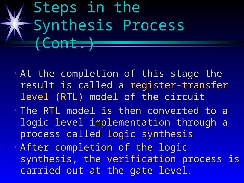
• At the completion of this stage the result is called At the completion of this stage the result is called a a register-transfer level (RTL)register-transfer level (RTL) model of the model of the circuitcircuit
• The RTL model is then converted to a logic level The RTL model is then converted to a logic level implementation through a process called implementation through a process called logic logic synthesissynthesis
• After completion of the logic synthesis, the After completion of the logic synthesis, the verification verification process is carried out at the gate levelprocess is carried out at the gate level ..

The Integrated Circuit Design Process
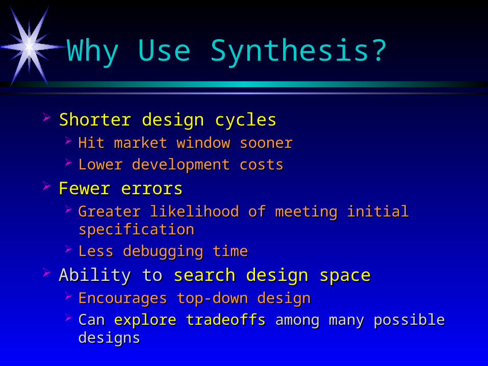
Why Use Synthesis?
Shorter design cyclesShorter design cycles Hit market window soonerHit market window sooner Lower development costsLower development costs
Fewer errorsFewer errors Greater likelihood of meeting initial specificationGreater likelihood of meeting initial specification Less debugging timeLess debugging time
Ability to Ability to search design spacesearch design space Encourages top-down designEncourages top-down design Can Can explore tradeoffsexplore tradeoffs among many possible designs among many possible designs
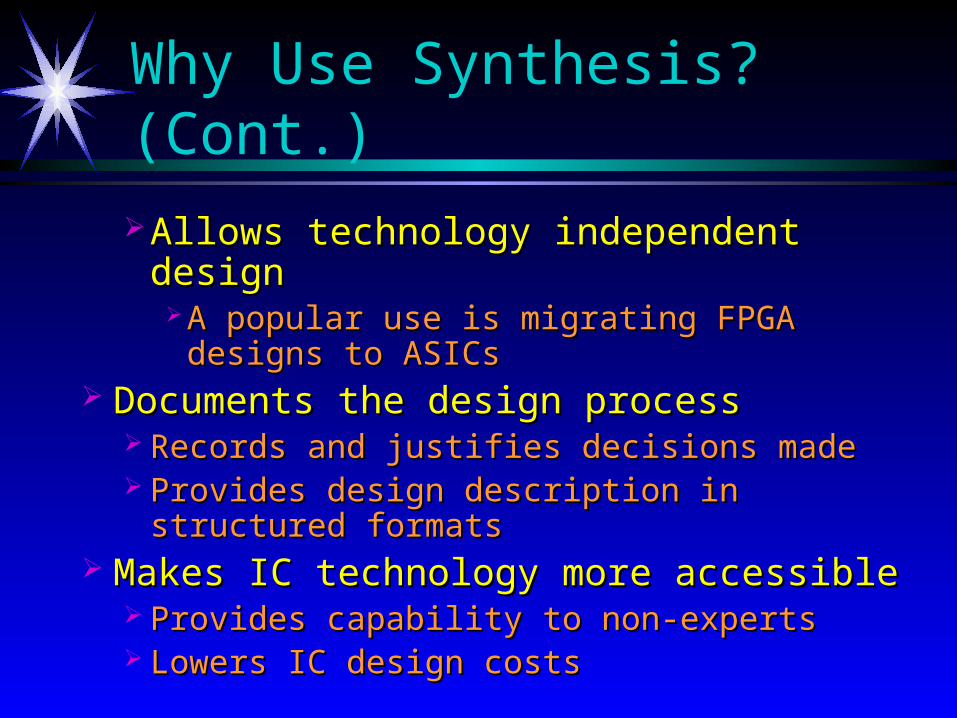
Why Use Synthesis? (Cont.)
Allows technology independent designAllows technology independent design A popular use is migrating FPGA designs to A popular use is migrating FPGA designs to
ASICsASICs Documents the design processDocuments the design process
Records and justifies decisions madeRecords and justifies decisions made Provides design description in structured formatsProvides design description in structured formats
Makes IC technology more accessibleMakes IC technology more accessible Provides capability to non-expertsProvides capability to non-experts Lowers IC design costsLowers IC design costs
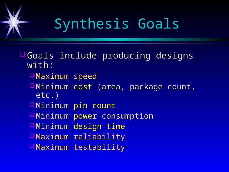
Synthesis Goals
Goals include producing designs with:Goals include producing designs with: Maximum speedMaximum speed Minimum Minimum costcost (area, package count, etc.) (area, package count, etc.) Minimum Minimum pin countpin count Minimum Minimum power power consumptionconsumption Minimum Minimum design timedesign time Maximum reliabilityMaximum reliability Maximum testabilityMaximum testability
Design Constraints
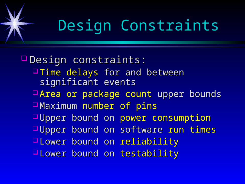
Design constraints:Design constraints: Time delaysTime delays for and between significant events for and between significant events Area or package countArea or package count upper bounds upper bounds Maximum Maximum number of pinsnumber of pins Upper bound on Upper bound on power consumptionpower consumption Upper bound on software Upper bound on software run timesrun times Lower bound on Lower bound on reliabilityreliability Lower bound on Lower bound on testabilitytestability
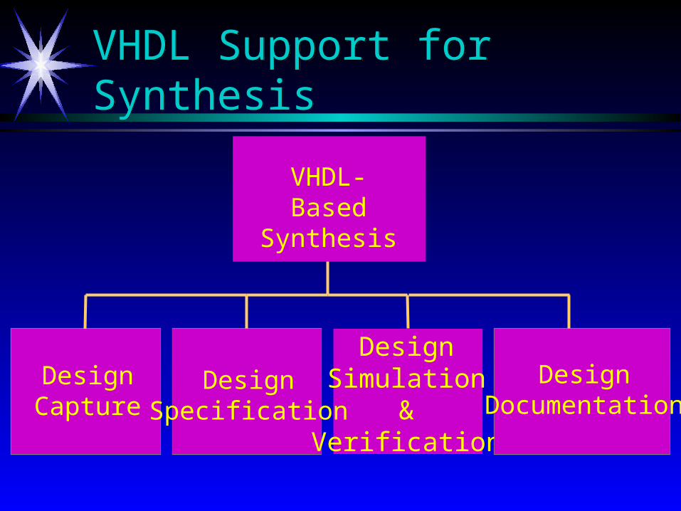
VHDL Support for SynthesisVHDL Support for Synthesis
DesignCapture
DesignSimulation
&Verification
DesignSpecification
DesignDocumentation
VHDL-BasedSynthesis
Design CaptureDesign Capture
VHDL captures the details of a digital design in a VHDL captures the details of a digital design in a machine-readable formmachine-readable form, entered into a CAD , entered into a CAD system.system.
VHDL is an alternative to a VHDL is an alternative to a schematic-basedschematic-based design entry.design entry.
Logic synthesisLogic synthesis and and RTLRTL synthesis tools are synthesis tools are design capture environments. design capture environments.
Over 90% of designers use Over 90% of designers use VHDL VHDL for this purpose for this purpose (EE Times, 1996).(EE Times, 1996).
Design SpecificationDesign Specification
In a In a structured design flowstructured design flow, VHDL captures , VHDL captures the behavioral, interface and performance-the behavioral, interface and performance-related aspects of the design.related aspects of the design.
The VHDL representation can then be The VHDL representation can then be synthesizedsynthesized using behavioral synthesis and using behavioral synthesis and advanced RTL synthesis.advanced RTL synthesis.
Design Simulation and VerificationDesign Simulation and Verification
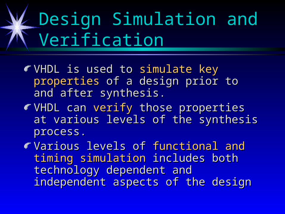
VHDL is used to VHDL is used to simulate key propertiessimulate key properties of of a design prior to and after synthesis.a design prior to and after synthesis.VHDL can VHDL can verifyverify those properties at those properties at various levels of the synthesis process.various levels of the synthesis process.Various levels of Various levels of functional and timing functional and timing simulationsimulation includes both technology includes both technology dependent and independent aspects of the dependent and independent aspects of the designdesign
Design DocumentationDesign Documentation
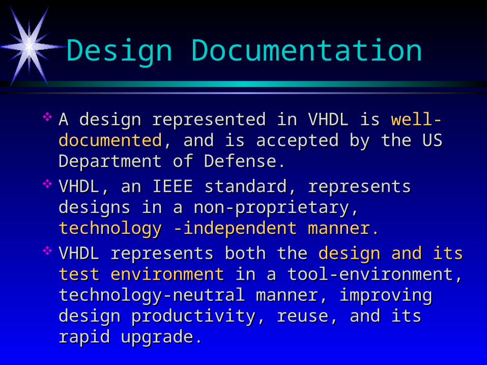
A design represented in VHDL is A design represented in VHDL is well-documentedwell-documented, , and is accepted by the US Department of Defense.and is accepted by the US Department of Defense.
VHDL, an IEEE standard, represents designs in a VHDL, an IEEE standard, represents designs in a non-proprietary, non-proprietary, technology -independent manner.technology -independent manner.
VHDL represents both the VHDL represents both the design and its test design and its test environmentenvironment in a tool-environment, technology- in a tool-environment, technology-neutral manner, improving design productivity, neutral manner, improving design productivity, reuse, and its rapid upgrade.reuse, and its rapid upgrade.

Definitions
Control-flowControl-flowThe operation of hardware in terms of the The operation of hardware in terms of the loops, loops, conditional branches, and orderingconditional branches, and ordering of functions of functions
Data pathsData pathsThe hardware which stores and performs The hardware which stores and performs operations operations on dataon data
Gate levelGate levelThe operations and storage elements can be The operations and storage elements can be described by described by logic gateslogic gates such as NAND and OR such as NAND and OR
Definitions (Cont.)
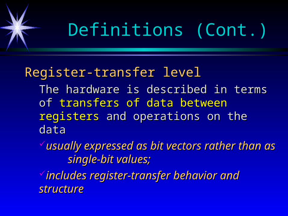
Register-transfer levelRegister-transfer levelThe hardware is described in terms of The hardware is described in terms of transfers of transfers of data between registersdata between registers and operations on the data and operations on the datausually expressed as bit vectors rather than as usually expressed as bit vectors rather than as single-bit values; single-bit values; includes register-transfer behavior and structureincludes register-transfer behavior and structure

Gajski and Kuhn’s Y Chart
Physical/Geometry
StructuralBehavioral
Processor
Hardware Modules
ALUs, RegistersGates, FFs
Transistors
SystemsAlgorithms
Register TransferLogic
Transfer Functions
Architectural
Algorithmic
Functional Block
Logic
Circuit
Rectangles
Cell, Module Plans
Floor Plans
Clusters
Physical Partitions

Synthesis Categories
Algorithm synthesisAlgorithm synthesisSynthesis from design requirements toSynthesis from design requirements to control-flow control-flowLargely a Largely a manualmanual process process
Behavioral to Register-transfer synthesisBehavioral to Register-transfer synthesisAlso referred to as “Also referred to as “high-level” high-level” synthesissynthesisSynthesis from either abstract, control-flow, or register-Synthesis from either abstract, control-flow, or register-
transfer behavior totransfer behavior to register-transfer structure register-transfer structure
Logic synthesisLogic synthesisSynthesis from register-transfer structures or Boolean Synthesis from register-transfer structures or Boolean
equations to equations to gate-level logicgate-level logic
+
*
+
*
E(7:0) A(7:0) B(7:0)
G(15:0)F(15:0)
D(7:0)C(7:0)
+
*
+
*
E(7:0) A(7:0) B(7:0)
G(15:0)F(15:0)
D(7:0)C(7:0) t1
t2
t3
[Parker84]
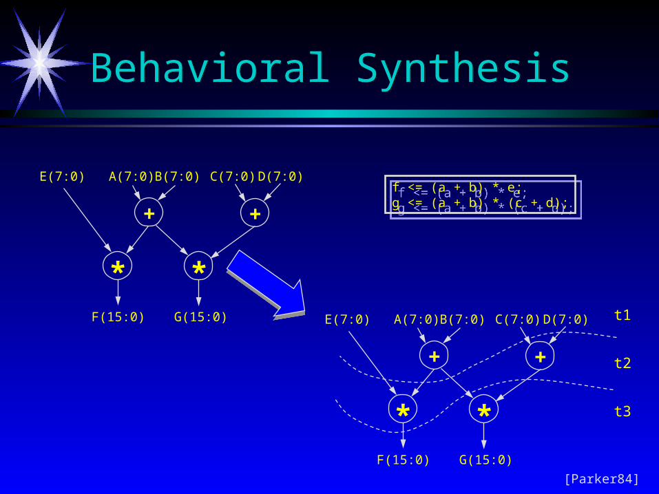
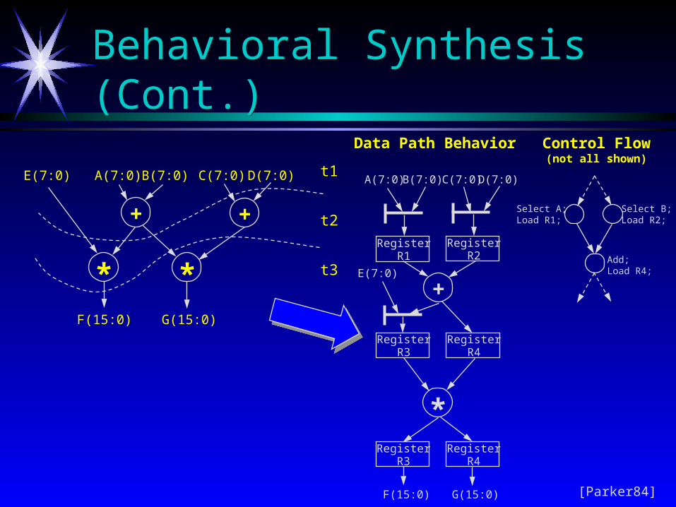
f <= (a + b) * e;g <= (a + b) * (c + d);
f <= (a + b) * e;g <= (a + b) * (c + d);
Behavioral SynthesisBehavioral Synthesis
+
*
+
*
E(7:0) A(7:0) B(7:0)
G(15:0)F(15:0)
D(7:0)C(7:0) t1
t2
t3
Select B;Load R2;
Select A;Load R1;
Add;Load R4;
RegisterR1
RegisterR2
RegisterR3
RegisterR4
+
*Register
R3Register
R4
E(7:0)
A(7:0) B(7:0) D(7:0)C(7:0)
G(15:0)F(15:0)
Data Path Behavior Control Flow(not all shown)
[Parker84]
Behavioral Synthesis (Cont.)Behavioral Synthesis (Cont.)
RegisterR1
RegisterR2
RegisterR3
RegisterR4
+
*Register
R3Register
R4
E(7:0)
A(7:0) B(7:0) D(7:0)C(7:0)
G(15:0)F(15:0)
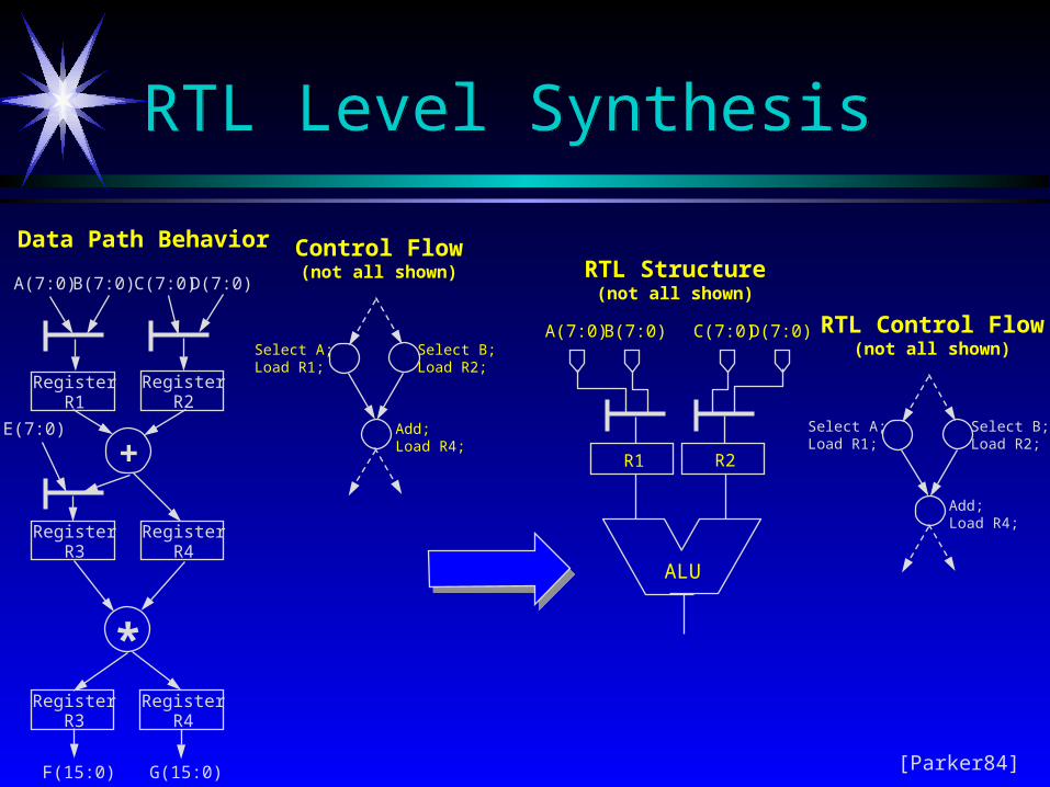
Data Path Behavior
Select B;Load R2;
Select A;Load R1;
Add;Load R4;
Control Flow(not all shown)
R1 R2
A(7:0) B(7:0) D(7:0)C(7:0)
ALU
RTL Structure(not all shown)
Select B;Load R2;
Select A;Load R1;
Add;Load R4;
RTL Control Flow(not all shown)
[Parker84]
RTL Level SynthesisRTL Level Synthesis
BehavioralSynthesis
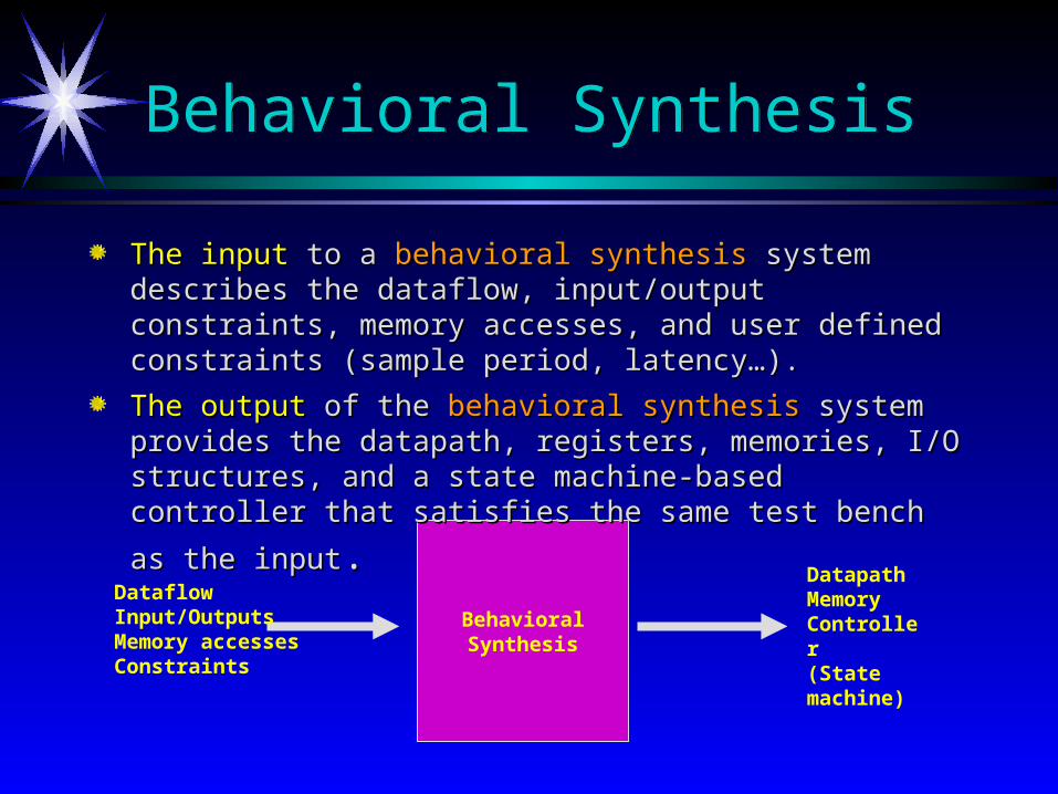
DataflowInput/OutputsMemory accessesConstraints
DatapathMemoryController (State machine)
Behavioral SynthesisBehavioral Synthesis
The inputThe input to a to a behavioral synthesisbehavioral synthesis system describes the dataflow, system describes the dataflow, input/output constraints, memory accesses, and user defined input/output constraints, memory accesses, and user defined constraints (sample period, latency…). constraints (sample period, latency…).
The outputThe output of the of the behavioral synthesisbehavioral synthesis system provides the datapath, system provides the datapath, registers, memories, I/O structures, and a state machine-based registers, memories, I/O structures, and a state machine-based
controller that satisfies the same test bench as the inputcontroller that satisfies the same test bench as the input..

Complex Multiplication: Z = ( a + b j) * ( c + d j ). Input Data: Available serially a, b, c, d. Real { Z } = Real part of Z = a*c - b*d Im { Z } = Imaginary part of Z = a*d + b*c Output Constraints: Real { Z } and Im { Z } to be available on separate portsFind Best Design (Area, Latency, Throughput, …)Data flow
I/O Constraints
User Constraints Algorithmic level description
Behavioral Synthesis Example (Cont.)Behavioral Synthesis Example (Cont.)
Design Specification:Design Specification:
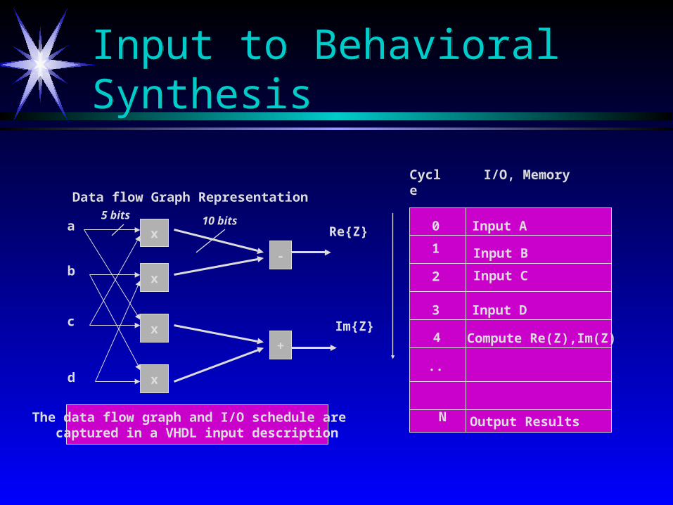
Data flow Graph Representation
x
x
x
x
-
+
a
b
c
d
Re{Z}
Im{Z}
Cycle I/O, Memory
2
3
4
..
N
1 Input B
Input C
Input D
Compute Re(Z),Im(Z)
Output Results
0
Input to Behavioral SynthesisInput to Behavioral Synthesis
The data flow graph and I/O schedule are captured in a VHDL input description
Input A5 bits 10 bits
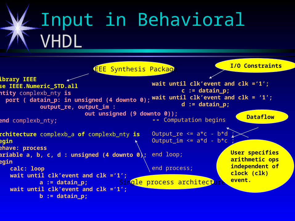
Input in Behavioral VHDLInput in Behavioral VHDL
Library IEEEUse IEEE.Numeric_STD.allEntity complexb_nty is port ( datain_p: in unsigned (4 downto 0); output_re, output_im : out unsigned (9 downto 0)); end complexb_nty;
Architecture complexb_a of complexb_nty is beginbehave: processvariable a, b, c, d : unsigned (4 downto 0); begin
calc: loopwait until clk’event and clk =‘1’;
a := datain_p; wait until clk’event and clk =‘1’;
b := datain_p;
wait until clk’event and clk =‘1’; c := datain_p;
wait until clk’event and clk = ‘1’; d := datain_p;
-- Computation begins
Output_re <= a*c - b*d ; Output_im <= a*d - b*c ;
end loop;
end process;
end complexb_a; Single process architecture
IEEE Synthesis Package
User specifiesarithmetic opsindependent ofclock (clk) event.
I/O Constraints
Dataflow

Results from Behavioral SynthesisResults from Behavioral Synthesis
READ A B C D
MULT_1 A*C A*D
MULT_2 B*C B*D
ADD_1 AC*-B*D
ADD_2 A*D+B*C
Cycles 0 1 2 3 4
Metric Value
Area 1700 gates
Latency 250 ns
Multipliers Two
Adders Two
Design Objective 1: Fast ImplementationClock cycle: 50 ns
Fast Small Power
Design ObjectiveArea = 1700 gatesArea = 1700 gatesLatency = 5*50 = 250 nsLatency = 5*50 = 250 nsMultipliers = TwoMultipliers = TwoAdder = Two Adder = Two
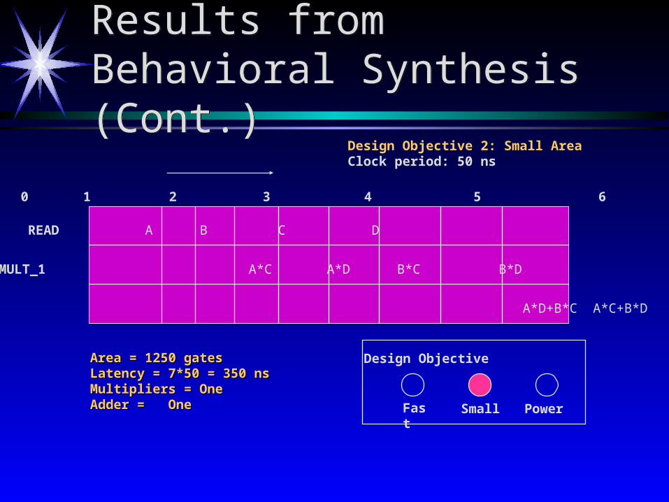
Results from Behavioral Synthesis (Cont.)Results from Behavioral Synthesis (Cont.)
Design Objective
Fast Small Power
Design Objective 2: Small AreaClock period: 50 ns
Cycles 0 1 2 3 4 5 6 7
READ A B C D
MULT_1 A*C A*D B*C B*D
ADD1 A*D+B*C A*C+B*D
Area = 1250 gatesArea = 1250 gatesLatency = 7*50 = 350 nsLatency = 7*50 = 350 nsMultipliers = OneMultipliers = OneAdder = OneAdder = One
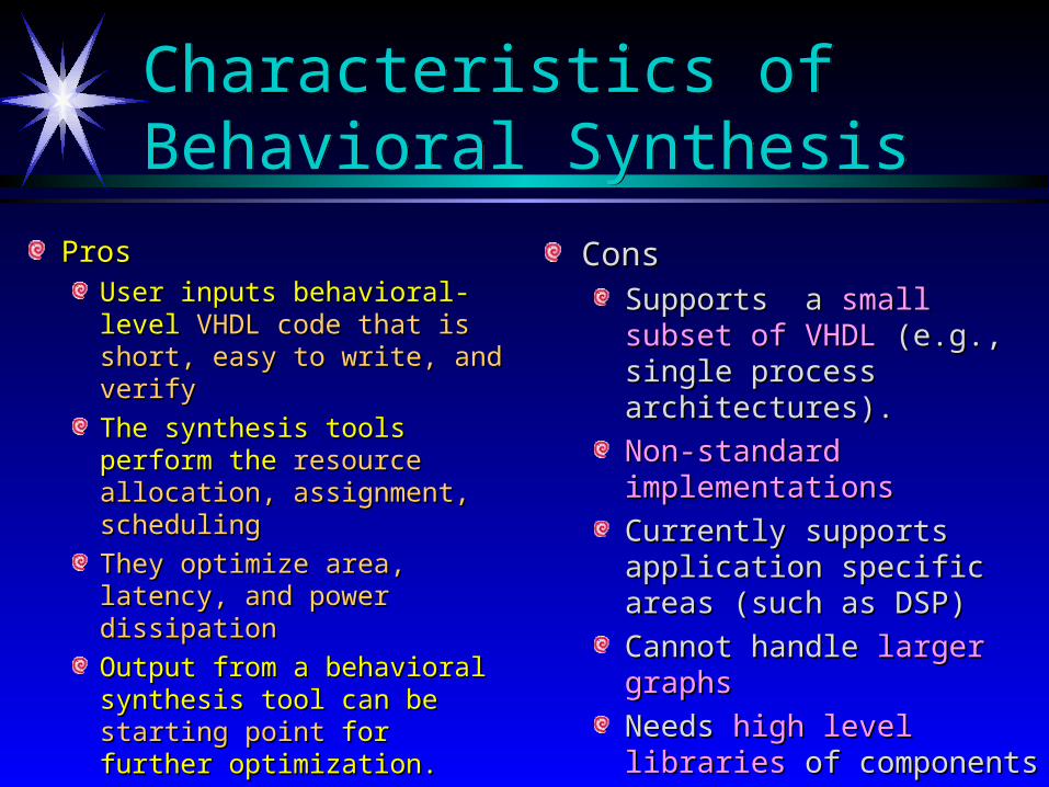
Characteristics of Behavioral SynthesisCharacteristics of Behavioral Synthesis
ProsPros
User inputs behavioral-level User inputs behavioral-level VHDL code that is short, easy VHDL code that is short, easy to write, and verifyto write, and verify
The synthesis tools perform The synthesis tools perform the the resource allocation, resource allocation, assignment, schedulingassignment, scheduling
They optimize area, latency,They optimize area, latency, and power dissipationand power dissipation
Output from a behavioral Output from a behavioral synthesis tool can be synthesis tool can be starting starting point point for further optimization.for further optimization.
Cons Cons
Supports a Supports a small subset of small subset of VHDLVHDL (e.g., single process (e.g., single process architectures).architectures).
Non-standard implementationsNon-standard implementations
Currently supports application Currently supports application specific areas (such as DSP)specific areas (such as DSP)
Cannot handle Cannot handle larger graphslarger graphs
Needs Needs high level librarieshigh level libraries of of componentscomponents
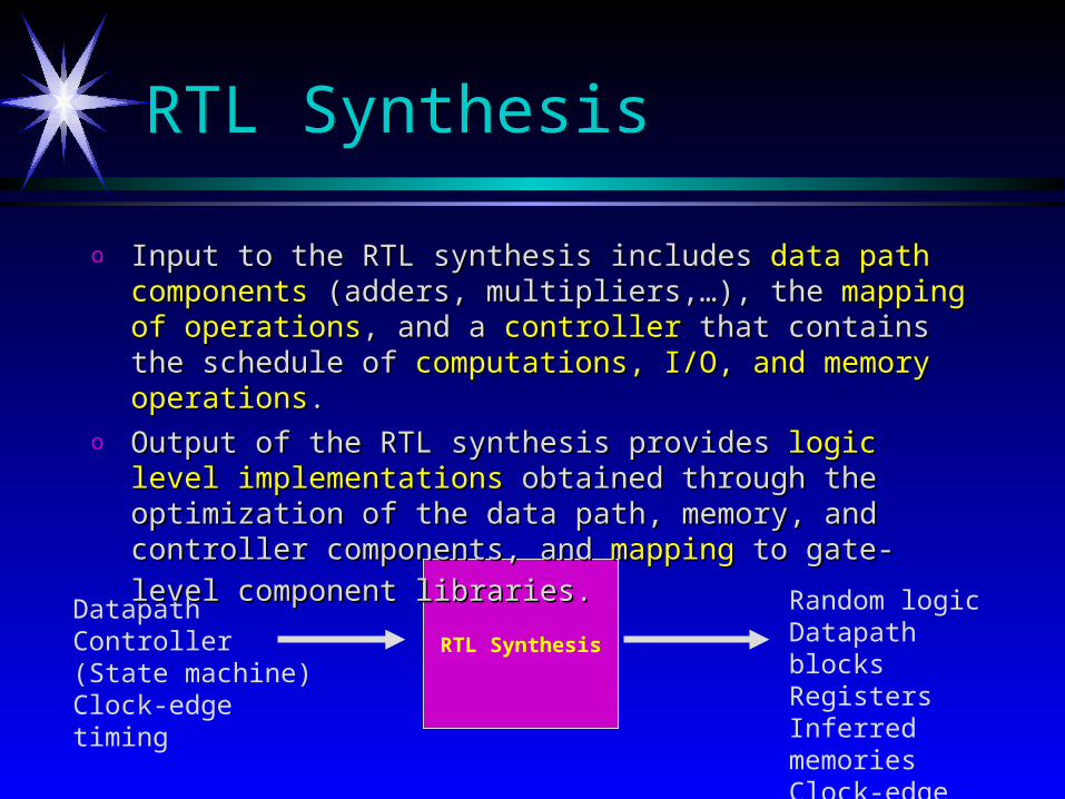
DatapathController (State machine)Clock-edge timing
RTL Synthesis
Random logicDatapath blocksRegistersInferred memoriesClock-edge timing
RTL SynthesisRTL Synthesis
o Input to the RTL synthesis includes Input to the RTL synthesis includes data pathdata path componentscomponents (adders, (adders, multipliers,…), the multipliers,…), the mapping of operationsmapping of operations, and a , and a controllercontroller that that contains the schedule of contains the schedule of computations, I/O, and memory operationscomputations, I/O, and memory operations..
o Output of the RTL synthesis provides Output of the RTL synthesis provides logic level implementationslogic level implementations obtained through the optimization of the data path, memory, and obtained through the optimization of the data path, memory, and
controller components, and controller components, and mappingmapping to gate-level component libraries. to gate-level component libraries.

RTL Synthesis ExampleRTL Synthesis Example
Design SpecificationDesign SpecificationMultiply Accumulate (MAC): Z = A*B + CInput data: Available seriallyComputation: Z = A*B + CAvailable Hardware: 1 Multiplier, 1 AdderOutput: Z available at end of computation.
REG1REG2
MULT
ADD
A
B
C
Z
Finite State Machine (FSM)
Clock
REG3
REG4
Le_add
Le_mult
Le_Z
REG5
Data path

RTL VHDL InputRTL VHDL Input
The architecture consists of a datapath and two finite state machine (FSM) processesThe architecture consists of a datapath and two finite state machine (FSM) processes
Datapath: processvariable reg_1, reg2 : unsigned (4 downto 0);variable reg_3, reg_4, reg_5: unsigned (9 downto 0); begin
wait until clk’event and clk’event=‘1’;if le_reg1 = ‘1’ then reg1 := a; end if; if le_reg2 = ‘1’ then reg2 := b; end if; if le_reg3 = ‘1’ then reg3 := c ; end if; if le_mult = ‘1’ then reg4 := reg1 * reg2;end if ; if le_add = ‘1’ then reg5 := reg4 + reg3; end if if le_z = ‘1’ then output <= reg5 ;end if;
end process;
Fsm: process(clk, reset); beginif clk’event and clk =‘1’ thenir reset = ‘1’ then cur_state <= s0;else cur_state <= next_state;
end if; end process; state_machine: process (cur_state, reset)begin case cur_state is
when s0 => next_state <= s1; le_reg1 <= ‘1’;when s1 => next_state <= s2; le_reg2 <= ‘1’; when s2 => next_state <= s3; le_reg3 <= ‘1’; when s3 => next_state <= s4; le_mult <= ‘1’; when s4 => next_state <= s5; le_add <=‘1’; when s5 => next_state <= s0;
le_z <= ‘1’; end case; end process;
Behavior at each clock edge is specifiedBehavior at each clock edge is specified
Area = 1400 gates, Latency = 300ns
Characteristics of RTL SynthesisCharacteristics of RTL Synthesis
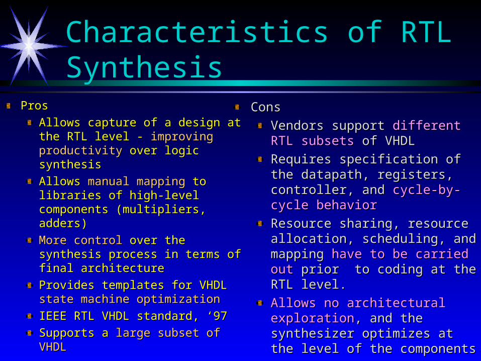
ProsPros
Allows capture of a design at the Allows capture of a design at the RTL level - RTL level - improving productivityimproving productivity over logic synthesisover logic synthesis
Allows Allows manual mappingmanual mapping to libraries to libraries of high-level components of high-level components (multipliers, adders)(multipliers, adders)
More controlMore control over the synthesis over the synthesis process in terms of final architectureprocess in terms of final architecture
Provides templates for VHDL Provides templates for VHDL state state machine optimizationmachine optimization
IEEE RTL VHDL standard, ‘97IEEE RTL VHDL standard, ‘97
Supports a Supports a large subset of VHDLlarge subset of VHDL
Cons Cons
Vendors support Vendors support different RTL different RTL subsetssubsets of VHDL of VHDL
Requires specification of the Requires specification of the datapath, registers, controller, and datapath, registers, controller, and cycle-by-cycle behaviorcycle-by-cycle behavior
Resource sharing, resource Resource sharing, resource allocation, scheduling, and mapping allocation, scheduling, and mapping have to be carried out have to be carried out prior to coding prior to coding at the RTL level.at the RTL level.
Allows no architectural explorationAllows no architectural exploration, , and the synthesizer optimizes at the and the synthesizer optimizes at the level of the componentslevel of the components

Logic SynthesisLogic Synthesis
Realizes the circuit with the optimal Realizes the circuit with the optimal number of “generic” gate level componentsnumber of “generic” gate level components
Two categories: Two categories:
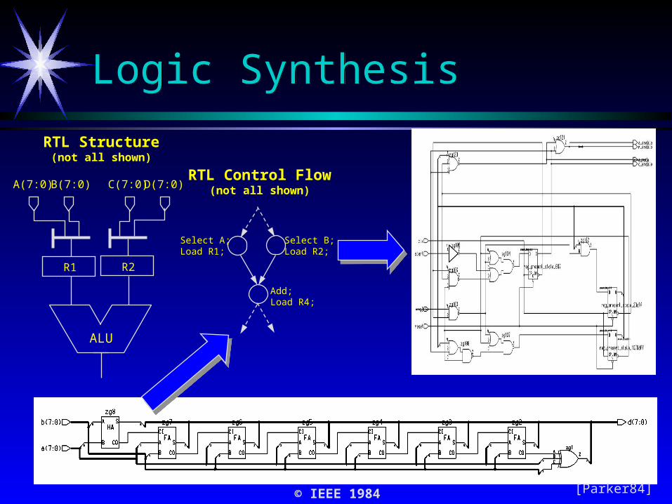
R1 R2
A(7:0) B(7:0) D(7:0)C(7:0)
ALU
RTL Structure(not all shown)
Select B;Load R2;
Select A;Load R1;
Add;Load R4;
RTL Control Flow(not all shown)
[Parker84]
Logic SynthesisLogic Synthesis
© IEEE 1984
Logic SynthesisLogic Synthesis
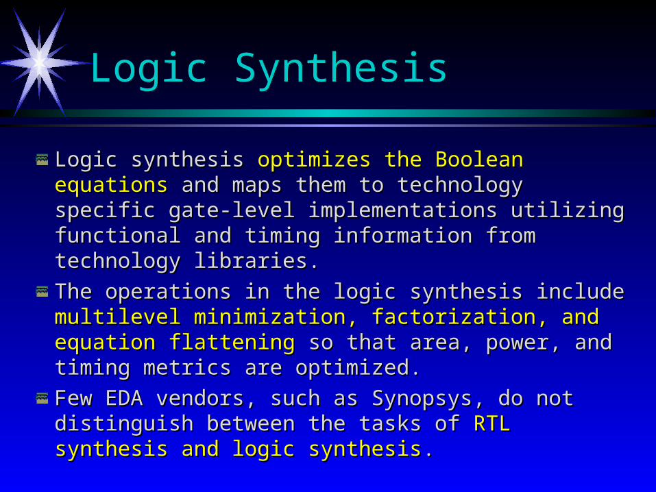
Logic synthesis Logic synthesis optimizes the Boolean equationsoptimizes the Boolean equations and and maps them to technology specific gate-level maps them to technology specific gate-level implementations utilizing functional and timing implementations utilizing functional and timing information from technology libraries.information from technology libraries.
The operations in the logic synthesis include The operations in the logic synthesis include multilevel multilevel minimization, factorization, and equation flatteningminimization, factorization, and equation flattening so so that area, power, and timing metrics are optimized. that area, power, and timing metrics are optimized.
Few EDA vendors, such as Synopsys, do not Few EDA vendors, such as Synopsys, do not distinguish between the tasks of distinguish between the tasks of RTL synthesis and RTL synthesis and logic synthesislogic synthesis. .
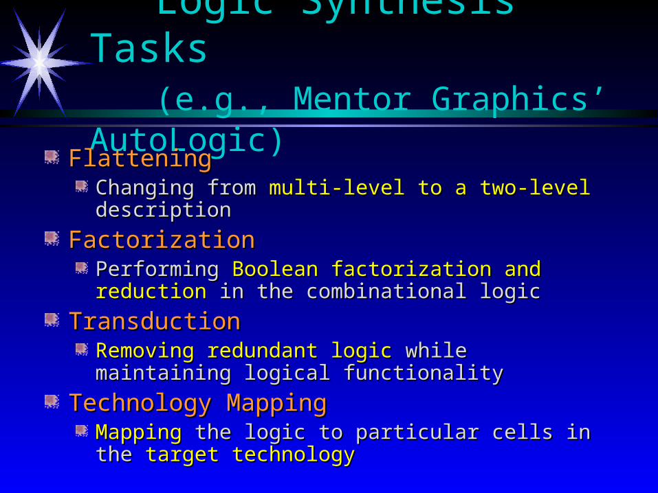
Logic Synthesis Tasks(e.g., Mentor Graphics’ AutoLogic)
FlatteningFlatteningChanging from Changing from multi-level to a two-levelmulti-level to a two-level description description
FactorizationFactorizationPerforming Performing Boolean factorization and reductionBoolean factorization and reduction in the in the combinational logiccombinational logic
TransductionTransductionRemoving redundant logicRemoving redundant logic while maintaining logical while maintaining logical functionalityfunctionality
Technology MappingTechnology MappingMappingMapping the logic to particular cells in the the logic to particular cells in the target target technologytechnology
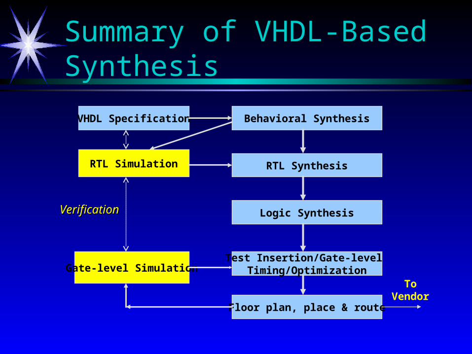
Summary of VHDL-Based SynthesisSummary of VHDL-Based Synthesis
Behavioral Synthesis
RTL Synthesis
Logic Synthesis
VHDL Specification
Test Insertion/Gate-level Timing/Optimization
Floor plan, place & route
RTL Simulation
Gate-level Simulation
VerificationVerification
ToVendor
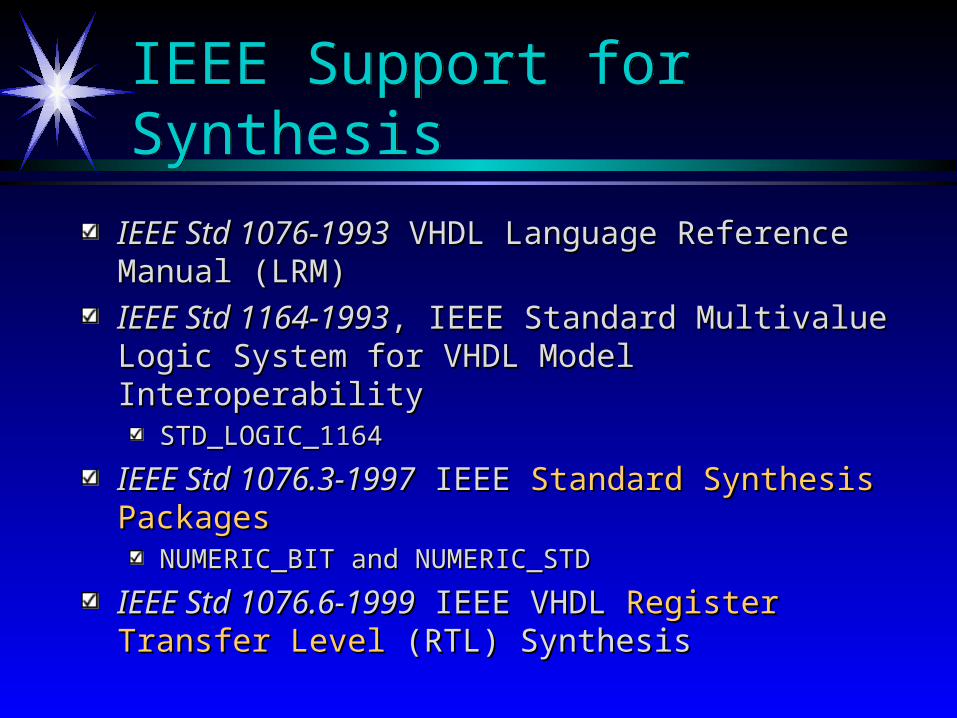
IEEE Support for SynthesisIEEE Support for Synthesis
IEEE Std 1076-1993IEEE Std 1076-1993 VHDL Language Reference Manual VHDL Language Reference Manual (LRM)(LRM)
IEEE Std 1164-1993IEEE Std 1164-1993, IEEE Standard Multivalue Logic , IEEE Standard Multivalue Logic System for VHDL Model InteroperabilitySystem for VHDL Model Interoperability
STD_LOGIC_1164STD_LOGIC_1164
IEEE Std 1076.3-1997IEEE Std 1076.3-1997 IEEE IEEE Standard Synthesis PackagesStandard Synthesis PackagesNUMERIC_BIT and NUMERIC_STDNUMERIC_BIT and NUMERIC_STD
IEEE Std 1076.6-1999IEEE Std 1076.6-1999 IEEE VHDL IEEE VHDL Register Transfer LevelRegister Transfer Level (RTL) Synthesis(RTL) Synthesis
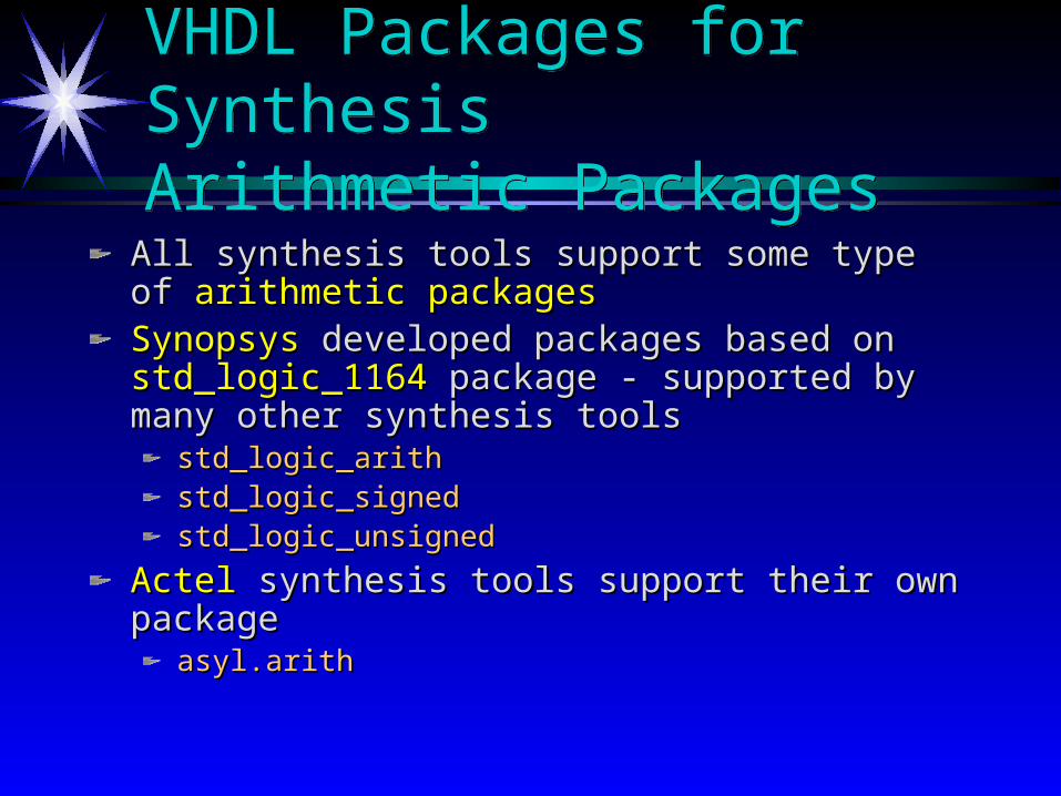
VHDL Packages for SynthesisArithmetic PackagesVHDL Packages for SynthesisArithmetic Packages
All synthesis tools support some type of All synthesis tools support some type of arithmetic arithmetic packagespackagesSynopsysSynopsys developed packages based on developed packages based on std_logic_1164std_logic_1164 package - supported by many other synthesis toolspackage - supported by many other synthesis tools
std_logic_arithstd_logic_arithstd_logic_signedstd_logic_signedstd_logic_unsignedstd_logic_unsigned
Actel Actel synthesis tools support their own packagesynthesis tools support their own packageasyl.arithasyl.arith
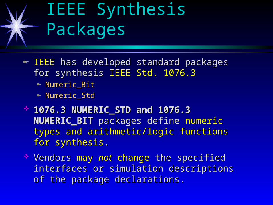
IEEE Synthesis PackagesIEEE Synthesis Packages
IEEEIEEE has developed standard packages for synthesis has developed standard packages for synthesis IEEE IEEE Std. 1076.3Std. 1076.3
Numeric_BitNumeric_Bit
Numeric_StdNumeric_Std
1076.3 NUMERIC_STD and 1076.3 NUMERIC_BIT1076.3 NUMERIC_STD and 1076.3 NUMERIC_BIT packages define packages define numeric types and arithmetic/logic numeric types and arithmetic/logic functions for synthesisfunctions for synthesis. .
Vendors Vendors may may notnot change change the specified interfaces or the specified interfaces or simulation descriptions of the package declarations.simulation descriptions of the package declarations.
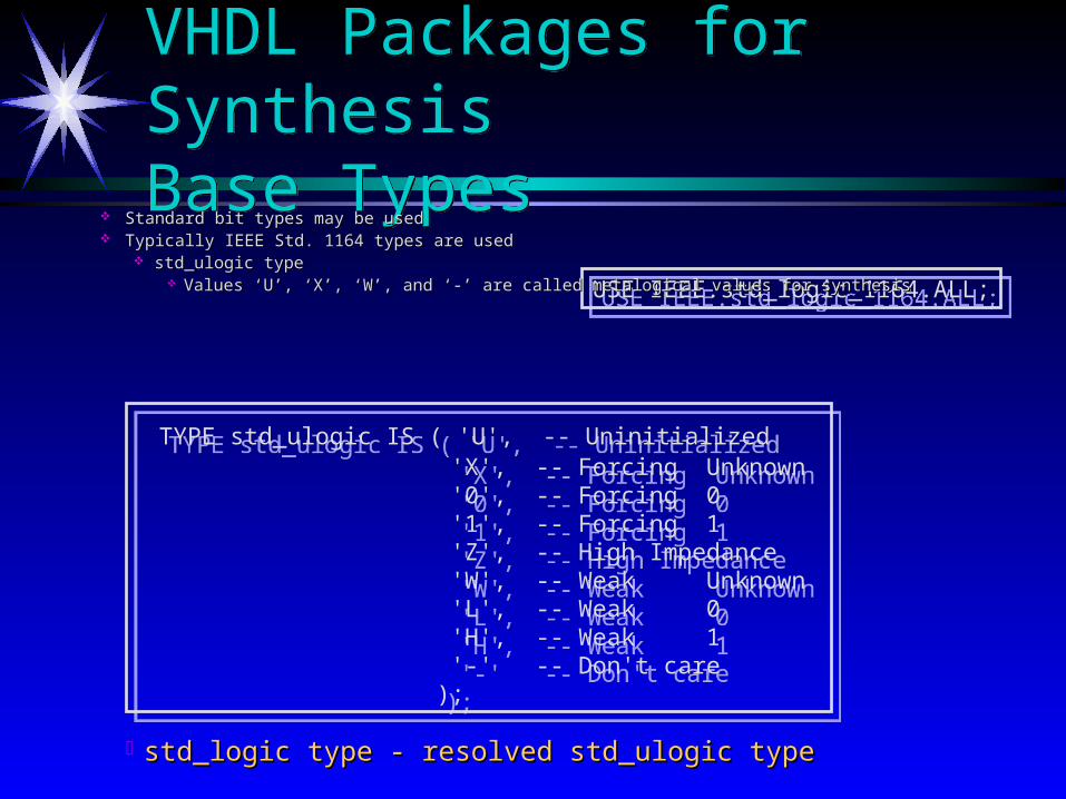
TYPE std_ulogic IS ( 'U', -- Uninitialized 'X', -- Forcing Unknown '0', -- Forcing 0 '1', -- Forcing 1 'Z', -- High Impedance 'W', -- Weak Unknown 'L', -- Weak 0 'H', -- Weak 1 '-' -- Don't care );
TYPE std_ulogic IS ( 'U', -- Uninitialized 'X', -- Forcing Unknown '0', -- Forcing 0 '1', -- Forcing 1 'Z', -- High Impedance 'W', -- Weak Unknown 'L', -- Weak 0 'H', -- Weak 1 '-' -- Don't care );
std_logic type - resolved std_ulogic typestd_logic type - resolved std_ulogic type
USE IEEE.std_logic_1164.ALL;USE IEEE.std_logic_1164.ALL;
VHDL Packages for SynthesisBase TypesVHDL Packages for SynthesisBase Types
Standard bit types may be usedStandard bit types may be used Typically IEEE Std. 1164 types are usedTypically IEEE Std. 1164 types are used
std_ulogic typestd_ulogic type Values ‘U’, ‘X’, ‘W’, and ‘-’ are called metalogical values for synthesisValues ‘U’, ‘X’, ‘W’, and ‘-’ are called metalogical values for synthesis
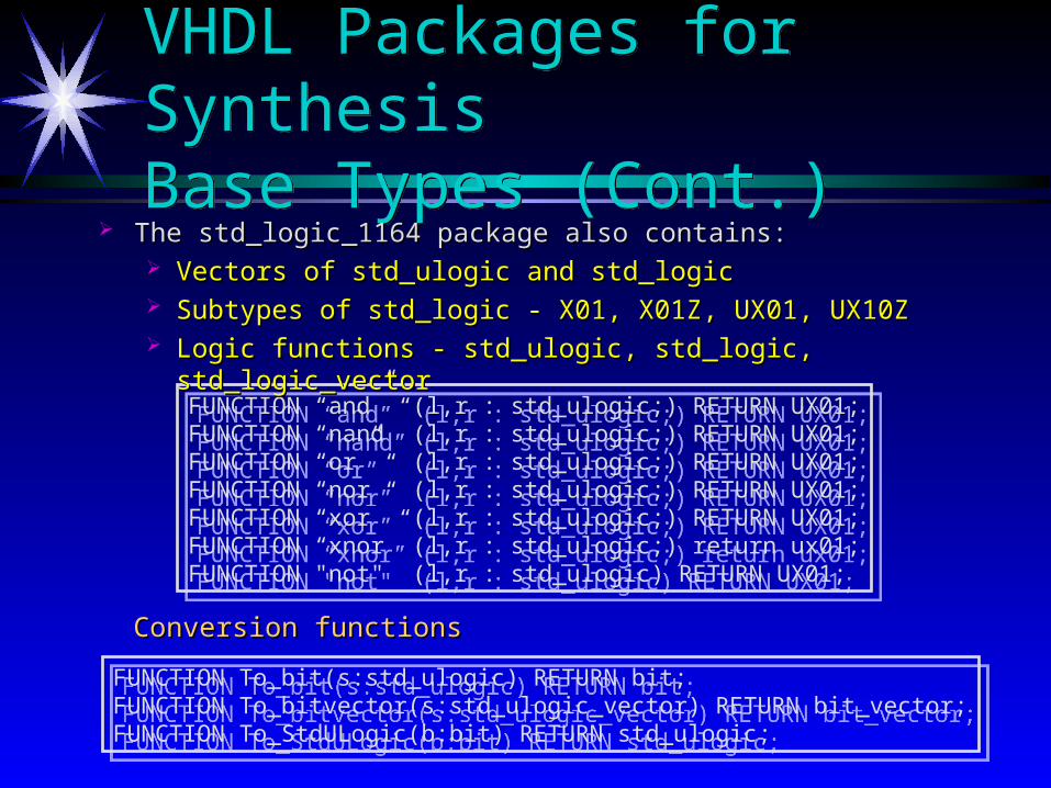
FUNCTION “and” (l,r : std_ulogic;) RETURN UX01;FUNCTION “nand” (l,r : std_ulogic;) RETURN UX01;FUNCTION “or” (l,r : std_ulogic;) RETURN UX01;FUNCTION “nor” (l,r : std_ulogic;) RETURN UX01;FUNCTION “xor” (l,r : std_ulogic;) RETURN UX01;FUNCTION “xnor” (l,r : std_ulogic;) return ux01;FUNCTION "not" (l,r : std_ulogic) RETURN UX01;
FUNCTION “and” (l,r : std_ulogic;) RETURN UX01;FUNCTION “nand” (l,r : std_ulogic;) RETURN UX01;FUNCTION “or” (l,r : std_ulogic;) RETURN UX01;FUNCTION “nor” (l,r : std_ulogic;) RETURN UX01;FUNCTION “xor” (l,r : std_ulogic;) RETURN UX01;FUNCTION “xnor” (l,r : std_ulogic;) return ux01;FUNCTION "not" (l,r : std_ulogic) RETURN UX01;
Conversion functionsConversion functions
FUNCTION To_bit(s:std_ulogic) RETURN bit;FUNCTION To_bitvector(s:std_ulogic_vector) RETURN bit_vector;FUNCTION To_StdULogic(b:bit) RETURN std_ulogic;
FUNCTION To_bit(s:std_ulogic) RETURN bit;FUNCTION To_bitvector(s:std_ulogic_vector) RETURN bit_vector;FUNCTION To_StdULogic(b:bit) RETURN std_ulogic;
VHDL Packages for SynthesisBase Types (Cont.)VHDL Packages for SynthesisBase Types (Cont.)
The std_logic_1164 package also contains:The std_logic_1164 package also contains: Vectors of std_ulogic and std_logicVectors of std_ulogic and std_logic Subtypes of std_logic - X01, X01Z, UX01, UX10ZSubtypes of std_logic - X01, X01Z, UX01, UX10Z Logic functions - std_ulogic, std_logic, std_logic_vectorLogic functions - std_ulogic, std_logic, std_logic_vector
VHDL Packages for SynthesisBase Types (Cont.)
Unknown functionsUnknown functions
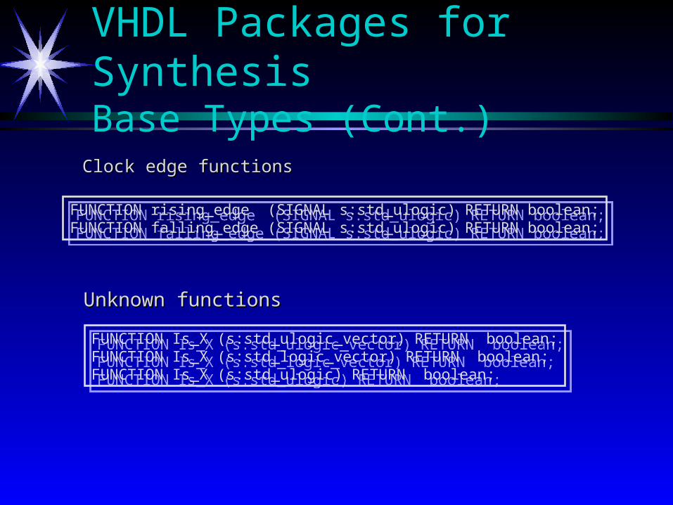
FUNCTION rising_edge (SIGNAL s:std_ulogic) RETURN boolean;FUNCTION falling_edge (SIGNAL s:std_ulogic) RETURN boolean;
FUNCTION rising_edge (SIGNAL s:std_ulogic) RETURN boolean;FUNCTION falling_edge (SIGNAL s:std_ulogic) RETURN boolean;
Clock edge functionsClock edge functions
FUNCTION Is_X (s:std_ulogic_vector) RETURN boolean;FUNCTION Is_X (s:std_logic_vector) RETURN boolean;FUNCTION Is_X (s:std_ulogic) RETURN boolean;
FUNCTION Is_X (s:std_ulogic_vector) RETURN boolean;FUNCTION Is_X (s:std_logic_vector) RETURN boolean;FUNCTION Is_X (s:std_ulogic) RETURN boolean;
Predefined Synthesis TypesPredefined Synthesis Types
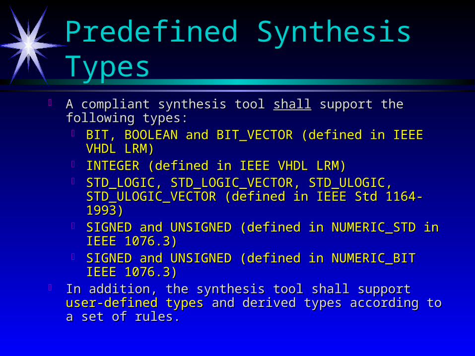
A compliant synthesis tool A compliant synthesis tool shallshall support the following types: support the following types: BIT, BOOLEAN and BIT_VECTOR (defined in IEEE VHDL BIT, BOOLEAN and BIT_VECTOR (defined in IEEE VHDL
LRM)LRM) INTEGER (defined in IEEE VHDL LRM)INTEGER (defined in IEEE VHDL LRM) STD_LOGIC, STD_LOGIC_VECTOR, STD_ULOGIC, STD_LOGIC, STD_LOGIC_VECTOR, STD_ULOGIC,
STD_ULOGIC_VECTOR (defined in IEEE Std 1164-1993)STD_ULOGIC_VECTOR (defined in IEEE Std 1164-1993) SIGNED and UNSIGNED (defined in NUMERIC_STD in IEEE SIGNED and UNSIGNED (defined in NUMERIC_STD in IEEE
1076.3)1076.3) SIGNED and UNSIGNED (defined in NUMERIC_BIT IEEE SIGNED and UNSIGNED (defined in NUMERIC_BIT IEEE
1076.3)1076.3) In addition, the synthesis tool shall support In addition, the synthesis tool shall support user-defined typesuser-defined types and and
derived types according to a set of rules.derived types according to a set of rules.
VHDL RTL KeywordsVHDL RTL Keywords
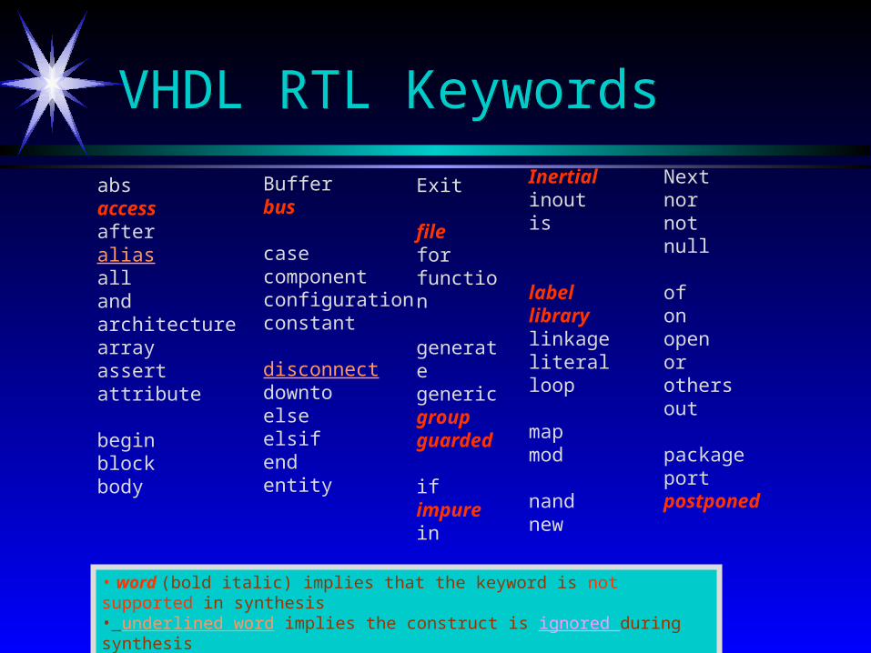
absaccessafteraliasallandarchitecturearrayassert attribute
beginblockbody
Bufferbus
casecomponentconfigurationconstant
disconnectdowntoelseelsifend entity
Exit
fileforfunction
generategenericgroupguarded
if impurein
Inertialinoutis
labellibrarylinkageliteralloop
mapmod
nandnew
Nextnornotnull
ofonopenor othersout
packageportpostponed
• word (bold italic) implies that the keyword is not supported in synthesis• underlined word implies the construct is ignored during synthesis
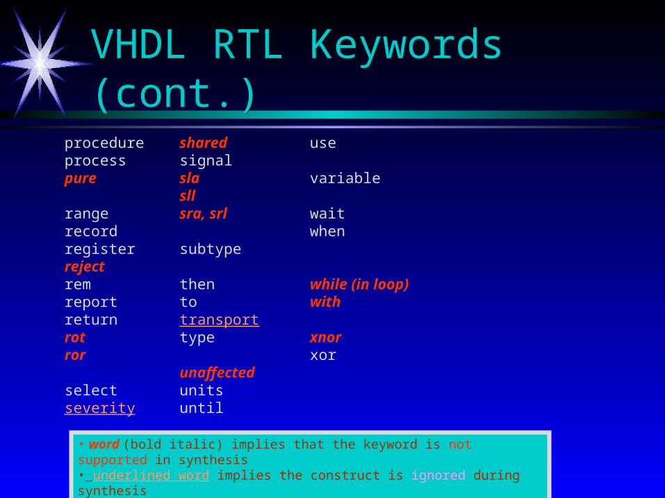
VHDL RTL Keywords(cont.)VHDL RTL Keywords(cont.)
procedureprocesspure
rangerecordregisterrejectremreportreturnrotror
selectseverity
sharedsignalslasllsra, srl
subtype
thentotransporttype
unaffectedunitsuntil
use
variable
waitwhen
while (in loop)with
xnorxor
• word (bold italic) implies that the keyword is not supported in synthesis• underlined word implies the construct is ignored during synthesis
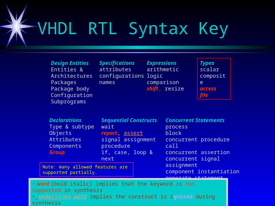
VHDL RTL Syntax KeyVHDL RTL Syntax Key
Concurrent Statementsprocessblockconcurrent procedure callconcurrent assertion concurrent signal assignmentcomponent instantiationgenerate statement
Design EntitiesEntities & ArchitecturesPackagesPackage bodyConfigurationSubprograms
Typesscalarcompositeaccessfile
DeclarationsType & subtypeObjectsAttributesComponents Group
Sequential Constructswaitreport, assertsignal assignmentprocedureif, case, loop & next
Specificationsattributesconfigurationsnames
Expressionsarithmeticlogiccomparisonshift, resize
Note: many allowed features are Note: many allowed features are supported partially.supported partially.
• word (bold italic) implies that the keyword is not supported in synthesis• underlined word implies the construct is ignored during synthesis

VHDL RTL Types VHDL RTL Types
ScalarEnumeration IntegerPhysicalFloating point
CompositeArrayRecord
Access File
• word (bold italic) implies that the keyword is not supported in synthesis• underlined word implies the construct is ignored during synthesis
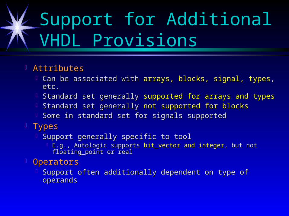
Support for Additional VHDL Provisions
AttributesAttributes Can be associated with Can be associated with arrays, blocks, signal, typesarrays, blocks, signal, types, etc., etc. Standard set generally Standard set generally supported for arrays and typessupported for arrays and types Standard set generally Standard set generally not supported for blocksnot supported for blocks Some in standard set for signals supportedSome in standard set for signals supported
TypesTypes Support generally specific to toolSupport generally specific to tool
E.g., Autologic supports E.g., Autologic supports bit_vector and integerbit_vector and integer, but not floating_point , but not floating_point or realor real
OperatorsOperators Support often additionally dependent on type of operandsSupport often additionally dependent on type of operands
Synthesis of Combinational CircuitsSynthesis of Combinational Circuits
Combinational circuits includeCombinational circuits include logic/arithmetic logic/arithmetic multiplexers and demultiplexersmultiplexers and demultiplexers encoders and decodersencoders and decoders comparatorscomparators Arithmetic Logic Units (ALUs)Arithmetic Logic Units (ALUs)
Both Both concurrent statements and sequentialconcurrent statements and sequential VHDL VHDL statements can be used to model combinational statements can be used to model combinational circuits.circuits.
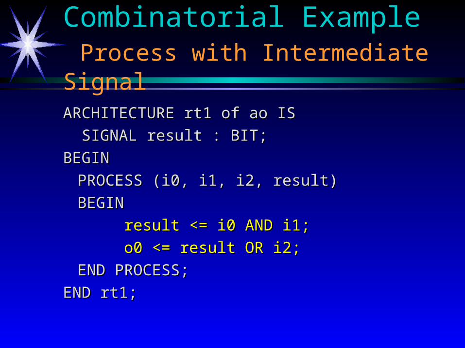
Combinatorial Example Process with Intermediate Signal
ARCHITECTURE rt1 of ao ISARCHITECTURE rt1 of ao IS
SIGNAL result : BIT;SIGNAL result : BIT;
BEGINBEGIN
PROCESS (i0, i1, i2, result)PROCESS (i0, i1, i2, result)
BEGINBEGIN
result <= i0 AND i1;result <= i0 AND i1;
o0 <= result OR i2;o0 <= result OR i2;
END PROCESS;END PROCESS;
END rt1;END rt1;
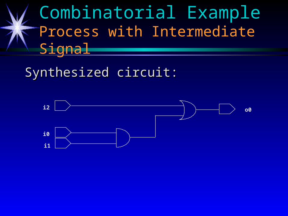
Combinatorial Example Process with Intermediate Signal
Synthesized circuit:Synthesized circuit:
i2
i0
i1
o0

ARCHITECTURE rt1 of mux4 ISARCHITECTURE rt1 of mux4 ISBEGINBEGIN
WITH sel SELECTWITH sel SELECTo0 <=o0 <= i0 WHEN “00”,i0 WHEN “00”,i1 WHEN “01”,i1 WHEN “01”,i2 WHEN “10”,i2 WHEN “10”,i3 WHEN OTHERS;i3 WHEN OTHERS;
END rt1;END rt1;
Combinatorial ExampleSelected Signal Assignment
i0
i1
i2
i3
sel (1:0)
o0
A
B
C
DS0 S1
Z
MUX41
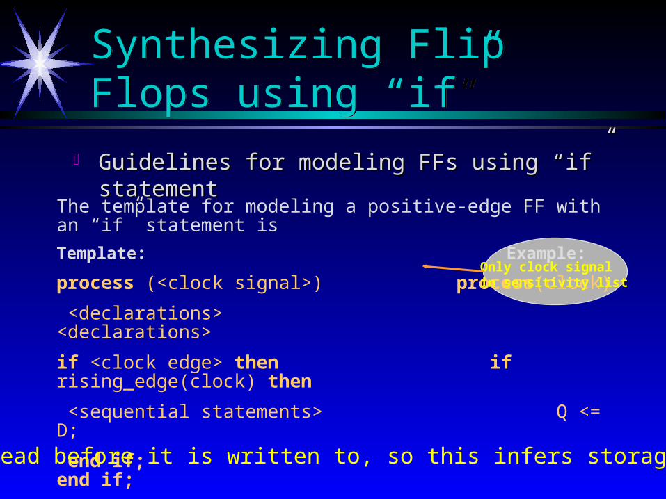
Synthesizing Flip Flops using “if”Synthesizing Flip Flops using “if”
Guidelines for modeling FFs using “if” statementGuidelines for modeling FFs using “if” statement
The template for modeling a positive-edge FF with an “if” statement is
Template: Example:
process (<clock signal>) process(clock)
<declarations> <declarations>
if <clock edge> then if rising_edge(clock) then
<sequential statements> Q <= D;
end if; end if;
end process end process;
Only clock signalin sensitivity list
Note: D is read before it is written to, so this infers storage required.
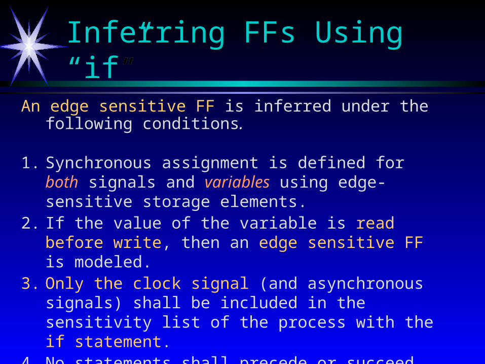
Inferring FFs Using “if”Inferring FFs Using “if”
An edge sensitive FF is inferred under the following conditions.
1. Synchronous assignment is defined for both signals and variables using edge-sensitive storage elements.
2. If the value of the variable is read before write, then an edge sensitive FF is modeled.
3. Only the clock signal (and asynchronous signals) shall be included in the sensitivity list of the process with the if statement.
4. No statements shall precede or succeed the if statement in the process.
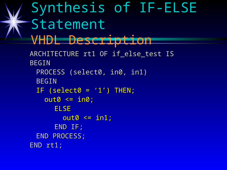
Synthesis of IF-ELSE Statement VHDL Description
ARCHITECTURE rt1 OF if_else_test ISARCHITECTURE rt1 OF if_else_test ISBEGINBEGIN
PROCESS (select0, in0, in1)PROCESS (select0, in0, in1)BEGINBEGIN
IF (select0 = ‘1’) THEN;IF (select0 = ‘1’) THEN; out0 <= in0;out0 <= in0;
ELSEELSE out0 <= in1;out0 <= in1; END IF;END IF;
END PROCESS;END PROCESS;END rt1;END rt1;

Synthesis of IF-ELSE StatementResulting Schematic
in1
in0
select0
out0M
UX
21
A
B
Z
S

Synthesis of Simple If StatementVHDL Description
ARCHITECTURE rt1 OF if_test ISARCHITECTURE rt1 OF if_test IS
BEGINBEGIN
PROCESS (select0, in0)PROCESS (select0, in0)
BEGINBEGIN
IF (select0= ‘1’) THEN;IF (select0= ‘1’) THEN;
out0 <= in0;out0 <= in0;
END IF;END IF;
END PROCESS;END PROCESS;
END rt1;END rt1;

Synthesis of Simple If StatementResulting Schematic
in0
select0
out0Q
E
D
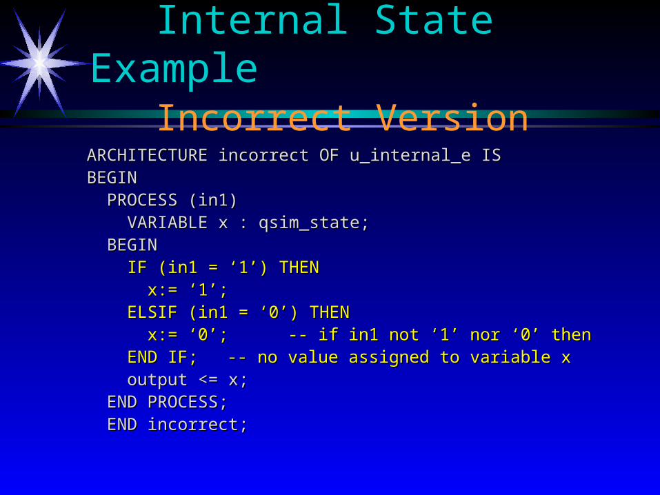
Internal State ExampleIncorrect Version
ARCHITECTURE incorrect OF u_internal_e ISARCHITECTURE incorrect OF u_internal_e ISBEGINBEGIN PROCESS (in1)PROCESS (in1) VARIABLE x : qsim_state;VARIABLE x : qsim_state; BEGINBEGIN IF (in1 = ‘1’) THENIF (in1 = ‘1’) THEN x:= ‘1’;x:= ‘1’; ELSIF (in1 = ‘0’) THENELSIF (in1 = ‘0’) THEN x:= ‘0’;x:= ‘0’; -- if in1 not ‘1’ nor ‘0’ then-- if in1 not ‘1’ nor ‘0’ then END IF;END IF; -- no value assigned to variable x-- no value assigned to variable x output <= x;output <= x; END PROCESS;END PROCESS; END incorrect;END incorrect;

Internal State ExampleCorrected Version
ARCHITECTURE correct OF u_internal_e ISARCHITECTURE correct OF u_internal_e ISBEGINBEGIN PROCESS (in1)PROCESS (in1) VARIABLE x : qsim_state;VARIABLE x : qsim_state; BEGINBEGIN x := ‘0’;x := ‘0’; IF (in1 = ‘1’) THENIF (in1 = ‘1’) THEN x:= ‘1’;x:= ‘1’; END IF;END IF; output <= x;output <= x; END PROCESS;END PROCESS; END correct;END correct;
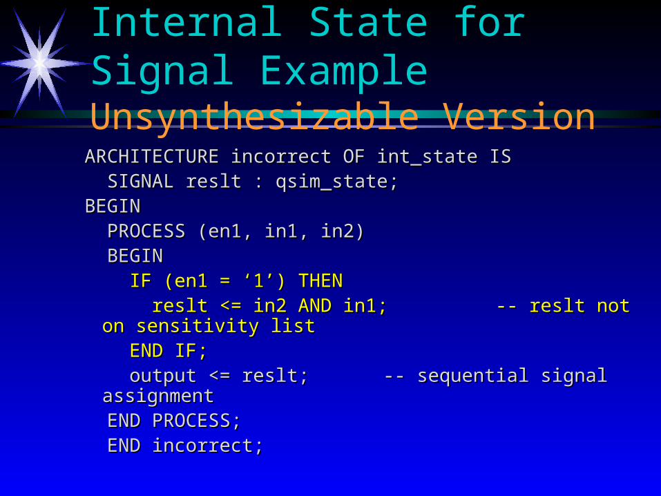
Internal State for Signal ExampleUnsynthesizable Version
ARCHITECTURE incorrect OF int_state ISARCHITECTURE incorrect OF int_state IS SIGNAL reslt : qsim_state;SIGNAL reslt : qsim_state;BEGINBEGIN PROCESS (en1, in1, in2)PROCESS (en1, in1, in2) BEGINBEGIN IF (en1 = ‘1’) THENIF (en1 = ‘1’) THEN reslt <= in2 AND in1;reslt <= in2 AND in1; -- reslt not on sensitivity list -- reslt not on sensitivity list END IF;END IF; output <= reslt;output <= reslt; -- sequential signal assignment -- sequential signal assignment END PROCESS;END PROCESS; END incorrect;END incorrect;
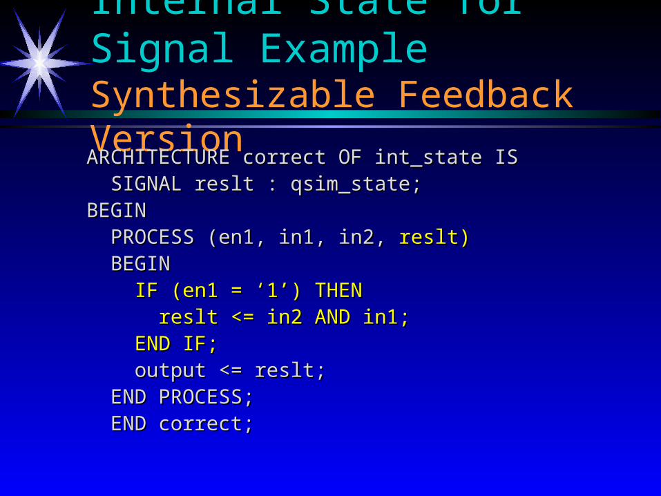
Internal State for Signal ExampleSynthesizable Feedback Version
ARCHITECTURE correct OF int_state ISARCHITECTURE correct OF int_state IS SIGNAL reslt : qsim_state;SIGNAL reslt : qsim_state;BEGINBEGIN PROCESS (en1, in1, in2, PROCESS (en1, in1, in2, reslt)reslt) BEGINBEGIN IF (en1 = ‘1’) THENIF (en1 = ‘1’) THEN reslt <= in2 AND in1;reslt <= in2 AND in1; END IF;END IF; output <= reslt;output <= reslt; END PROCESS;END PROCESS; END correct;END correct;

Internal State for Signal ExampleFeedback Version
in1
in2
en
output
MU
X21
Q
E
D
A
B
Z
S

Internal State for Signal ExampleSynthesizable without Feedback
ARCHITECTURE incorrect OF int_state ISARCHITECTURE incorrect OF int_state IS SIGNAL reslt : qsim_state;SIGNAL reslt : qsim_state;BEGINBEGIN PROCESS (en1, in1, in2)PROCESS (en1, in1, in2) BEGINBEGIN IF (en1 = ‘1’) THENIF (en1 = ‘1’) THEN reslt <= in2 AND in1;reslt <= in2 AND in1; END IF;END IF;END PROCESS;END PROCESS;output <= reslt;output <= reslt; -- concurrent signal assignment-- concurrent signal assignmentEND correct;END correct;
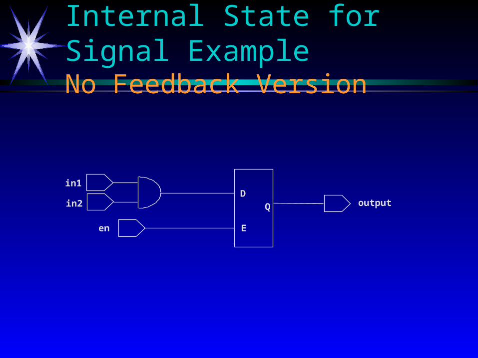
Internal State for Signal ExampleNo Feedback Version
in1
in2
en
outputQ
E
D

Registers and ClocksRegisters and Clocks
Clock typesClock types: : Allowed types for clock signals --Allowed types for clock signals -- BIT BIT, , STD_ULOGICSTD_ULOGIC
and their subtypes (and their subtypes (STD_LOGICSTD_LOGIC), ), with a minimum subset of ‘0’ and ‘1’, without the with a minimum subset of ‘0’ and ‘1’, without the metalogicalmetalogical
values (values (UU, , X, W, or “-”X, W, or “-”)).. Clock edges Clock edges Can be specified either Can be specified either
using the VHDL using the VHDL functionsfunctions FALLING_EDGEFALLING_EDGE and and RISING_EDGERISING_EDGE declared in declared in STD_LOGIC_1164STD_LOGIC_1164 or or
by by NUMERIC_BITNUMERIC_BIT, or , or through the use of through the use of if if and and waitwait statements (with some statements (with some restrictionsrestrictions).).
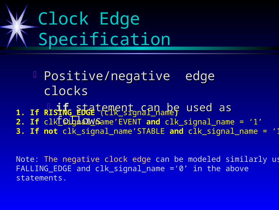
Clock Edge SpecificationClock Edge Specification
Positive/negative edge clocksPositive/negative edge clocks if if statement can be used as followsstatement can be used as follows
1. If RISING_EDGE (clk_signal_name)2. If clk_signal_name’EVENT and clk_signal_name = ‘1’3. If not clk_signal_name’STABLE and clk_signal_name = ‘1’
Note: The negative clock edge can be modeled similarly usingFALLING_EDGE and clk_signal_name =‘0’ in the above statements.

Clock Edge Specification (Cont.)Clock Edge Specification (Cont.)
Positive/negative clock edge specificationPositive/negative clock edge specification Using theUsing the wait until wait until statement in VHDL, the statement in VHDL, the
following statements are equivalentfollowing statements are equivalent
1. Wait until RISING_EDGE (clk_signal_name)2. Wait until Clk_signal_name = ‘1’3. Wait until Clk_signal_name’EVENT and clk_signal_name =‘1’4. Wait until not clk_signal_name’STABLE and clk_signal_name =‘1’
The wait statement should be the first statement in the process, whichcan cause problems when the process is required to be sensitive toother asynchronous inputs.

Inferring FFs Using“wait”Inferring FFs Using“wait”
Only one wait statement is allowed per process, and it shall be the first statement in the process.
This implies that asynchronous conditions cannot be modeled in the same process using the wait until construct.
Label: Process -- note labels are allowed for processes begin wait until CLOCK = ‘0’; -- Negative edge COUNT := COUNT + 1; -- COUNT may model edge-sensitive FF VAR := COUNT -- VAR is written to before it is read - no FF VAR := VAR + 1; Q <= D; -- Q also infers FF end process;

Clocked Register with Logic VHDL Description
ARCHITECTURE rt1 OF example ISARCHITECTURE rt1 OF example IS SIGNAL temp : BIT := ‘0’;SIGNAL temp : BIT := ‘0’; BEGINBEGIN latch: PROCESSlatch: PROCESS BEGINBEGIN WAIT UNTIL (clk = ‘1’);WAIT UNTIL (clk = ‘1’); temp <= NOT i0;temp <= NOT i0; END PROCESS latch;END PROCESS latch; o0 <= temp;o0 <= temp; END rt1;END rt1;
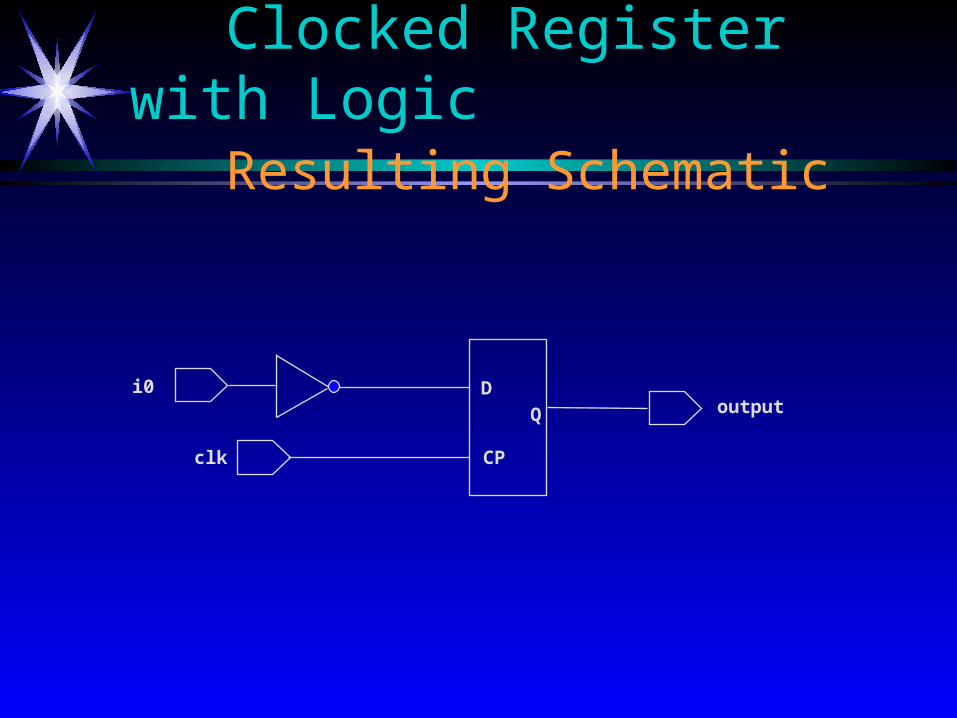
Clocked Register with LogicResulting Schematic
i0
clk
outputQ
CP
D

Logic after the RegisterVHDL Description
ARCHITECTURE rt1 OF example ISARCHITECTURE rt1 OF example IS SIGNAL temp : BIT := ‘0’;SIGNAL temp : BIT := ‘0’; BEGINBEGIN latch: PROCESSlatch: PROCESS BEGINBEGIN temp <= NOT i0;temp <= NOT i0; WAIT UNTIL (clk = ‘1’);WAIT UNTIL (clk = ‘1’); END PROCESS latch;END PROCESS latch; o0 <= temp;o0 <= temp; END rt1;END rt1;
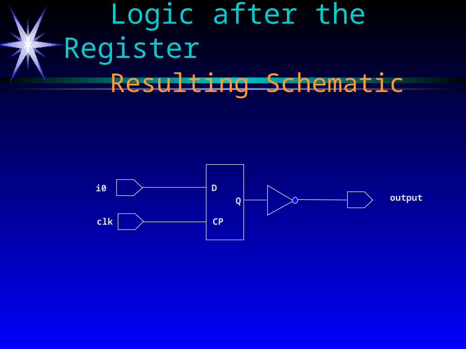
Logic after the RegisterResulting Schematic
i0
clk
outputQ
CP
D
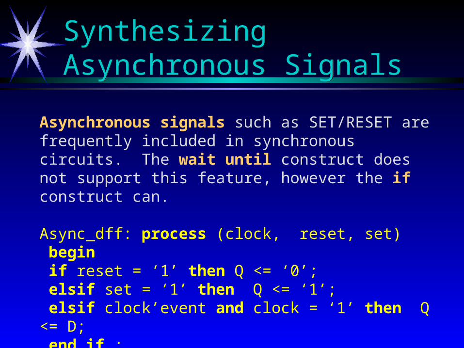
Synthesizing Asynchronous SignalsSynthesizing Asynchronous Signals
Asynchronous signals such as SET/RESET are frequently included in synchronous circuits. The wait until construct does not support this feature, however the if construct can.
Async_dff: process (clock, reset, set) begin if reset = ‘1’ then Q <= ‘0’; elsif set = ‘1’ then Q <= ‘1’; elsif clock’event and clock = ‘1’ then Q <= D; end if ; end process;

Level Sensitive D LatchLevel Sensitive D Latch
Use Use IFIF statement without statement without ElseElse clause clause
library IEEE;use IEEE.std_logic_1164.all;
ENTITY d_latch is PORT(d : IN std_logic; clk : IN std_logic; q : INOUT std_logic; qn : OUT std_logic);END d_latch;
ARCHITECTURE behavior OF d_latch IS BEGIN seq : PROCESS(d,clk) BEGIN IF(clk = '1') THEN q <= d; END IF; END PROCESS seq; qn <= not q;END behavior;
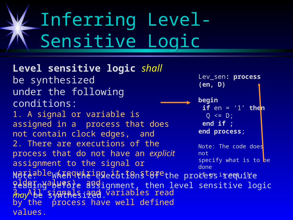
Inferring Level-Sensitive LogicInferring Level-Sensitive Logic
Level sensitive logic shall be synthesizedunder the following conditions: 1. A signal or variable is assigned in a process that does not contain clock edges, and 2. There are executions of the process that do not have an explicit assignment to the signal or variable (requiring it to store older values), and3. All signals and variables read by the process have well defined values.
Lev_sen: process (en, D)
begin if en = ‘1’ then Q <= D; end if ; end process;
Note: The code does not specify what is to be doneif en is not ‘1’.
Note: When the executions of the process require reading before assignment, then level sensitive logic may be synthesized.
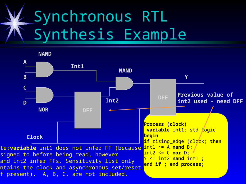
Synchronous RTL Synthesis ExampleSynchronous RTL Synthesis Example
DFF
DFF
A
B
C
D
Clock
Int1
Int2
Y
NAND
NOR
NAND
Process (clock) variable int1: std_logicbeginif rising_edge (clock) thenint1 := A nand B; int2 <= C nor D; Y <= int2 nand int1 ; end if ; end process;
Note:variable int1 does not infer FF (because it isassigned to before being read, howeverY and int2 infer FFs. Sensitivity list onlycontains the clock and asynchronous set/reset(if present). A, B, C, are not included.
Previous value ofint2 used – need DFF
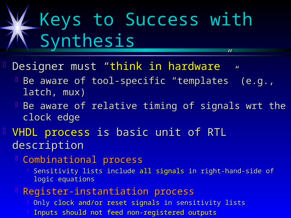
Keys to Success with Synthesis
Designer must “Designer must “think in hardwarethink in hardware”” Be aware of tool-specific “templates” (e.g., latch, mux)Be aware of tool-specific “templates” (e.g., latch, mux) Be aware of relative timing of signals wrt the clock edgeBe aware of relative timing of signals wrt the clock edge
VHDL processVHDL process is basic unit of RTL description is basic unit of RTL description Combinational processCombinational process
Sensitivity lists include Sensitivity lists include all signalsall signals in right-hand-side of logic equations in right-hand-side of logic equations
Register-instantiation processRegister-instantiation process Only Only clock and/or reset signalsclock and/or reset signals in sensitivity lists in sensitivity lists Inputs should not feed non-registered outputsInputs should not feed non-registered outputs
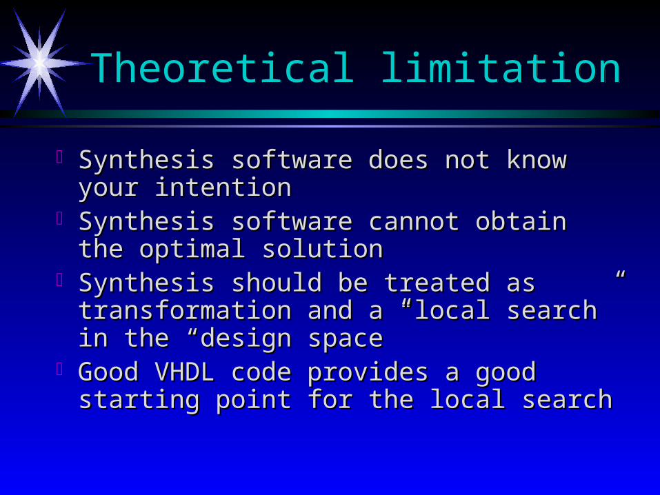
Theoretical limitationTheoretical limitation
Synthesis software does not know your Synthesis software does not know your intentionintention
Synthesis software cannot obtain the optimal Synthesis software cannot obtain the optimal solution solution
Synthesis should be treated as transformation Synthesis should be treated as transformation and a “local search” in the “design space”and a “local search” in the “design space”
Good VHDL code provides a good starting Good VHDL code provides a good starting point for the local search point for the local search
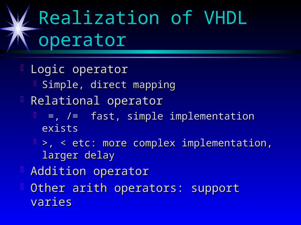
Realization of VHDL operatorRealization of VHDL operator
Logic operatorLogic operator Simple, direct mappingSimple, direct mapping
Relational operatorRelational operator =, /= fast, simple implementation exists=, /= fast, simple implementation exists >, < etc: more complex implementation, larger >, < etc: more complex implementation, larger
delay delay Addition operatorAddition operator Other arith operators: support variesOther arith operators: support varies
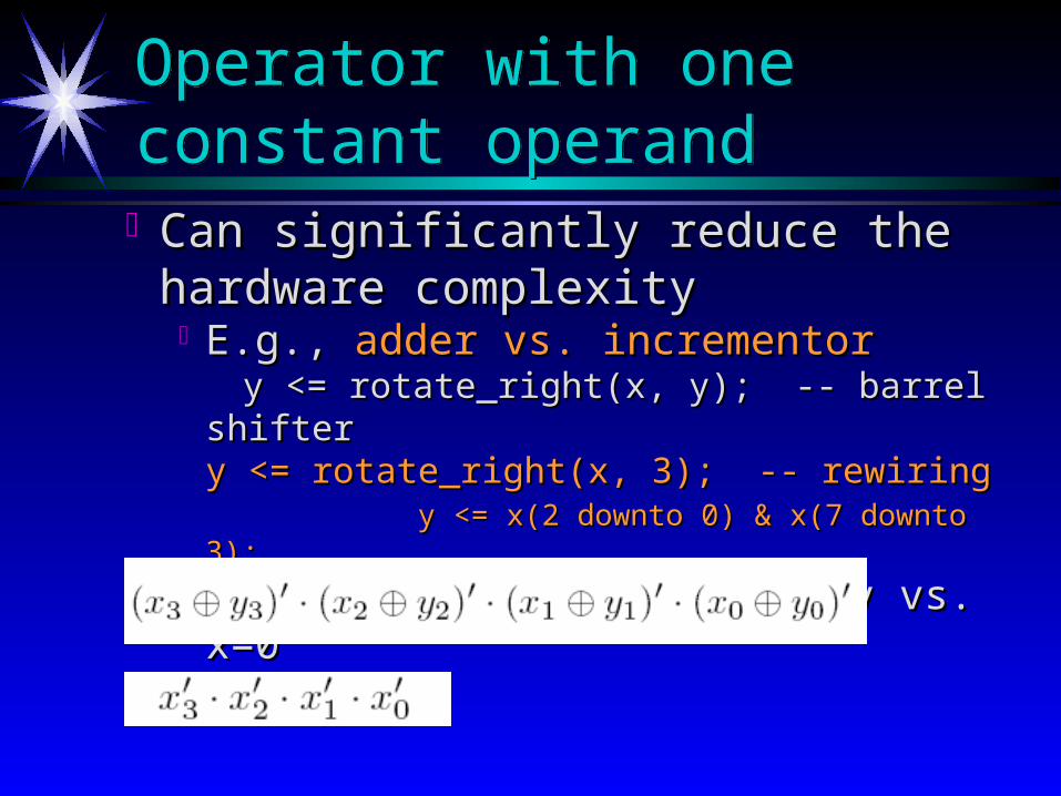
Can significantly reduce the hardware Can significantly reduce the hardware complexitycomplexity
E.g., E.g., adder vs. incrementoradder vs. incrementor y <= rotate_right(x, y); -- barrel shiftery <= rotate_right(x, y); -- barrel shifter
y <= rotate_right(x, 3); -- rewiringy <= rotate_right(x, 3); -- rewiringy <= x(2 downto 0) & x(7 downto 3);y <= x(2 downto 0) & x(7 downto 3);
E.g., 4-bit comparator: x=y vs. x=0E.g., 4-bit comparator: x=y vs. x=0
Operator with one constant operandOperator with one constant operand
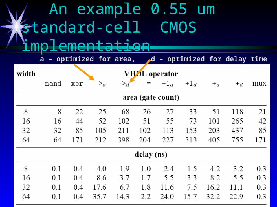
An example 0.55 um standard-cell CMOS implementationAn example 0.55 um standard-cell CMOS implementation
a – optimized for area, d – optimized for delay time

Use and synthesis of ‘Z’Use and synthesis of ‘Z’
Tri-state buffer:Tri-state buffer: Output with “high-impedance”Output with “high-impedance” Not a value in Boolean algebra Not a value in Boolean algebra Need special output circuitry (tri-state buffer) Need special output circuitry (tri-state buffer)
Bi-directional I/O pinsBi-directional I/O pins Tri-state busTri-state bus
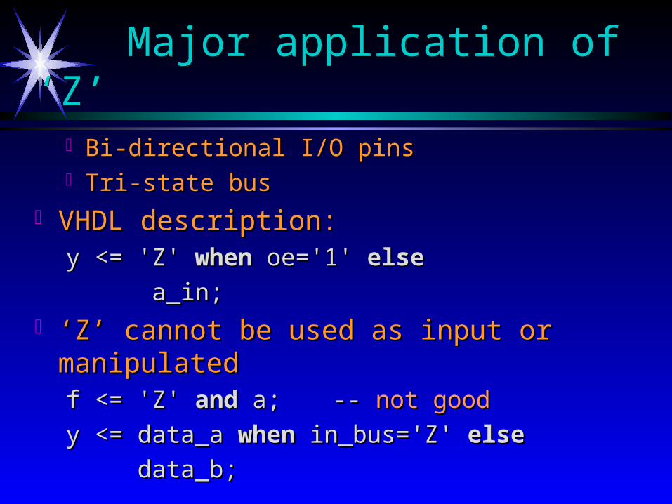
VHDL description:VHDL description:y <= 'Z' y <= 'Z' whenwhen oe='1' oe='1' elseelse
a_in;a_in; ‘‘Z’ cannot be used as input or manipulatedZ’ cannot be used as input or manipulated
f <= 'Z' f <= 'Z' andand a; a; -- -- not goodnot good
y <= data_a y <= data_a whenwhen in_bus='Z' in_bus='Z' elseelse
data_b;data_b;
Major application of ‘Z’ Major application of ‘Z’

Less clear:Less clear:withwith sel sel selectselect y <= 'Z' y <= 'Z' whenwhen "00", "00", '1' '1' whenwhen "01"|"11", "01"|"11", '0' '0' whenwhen othersothers;;
better:better:withwith sel sel selectselect tmp <= '1' tmp <= '1' whenwhen "01"|"11", "01"|"11", '0' '0' whenwhen othersothers;; y <= 'Z' y <= 'Z' whenwhen sel="00" sel="00" elseelse tmp;tmp;
Separate tri-state buffer from regular code:Separate tri-state buffer from regular code:

Bi-directional i/o pinsBi-directional i/o pins
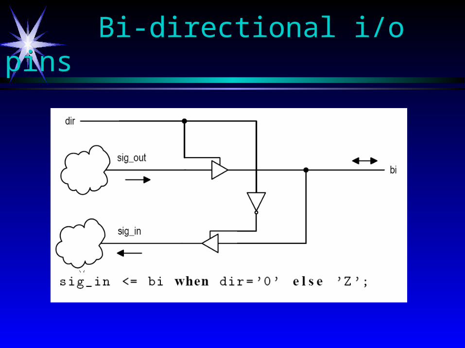
Bi-directional i/o pinsBi-directional i/o pins
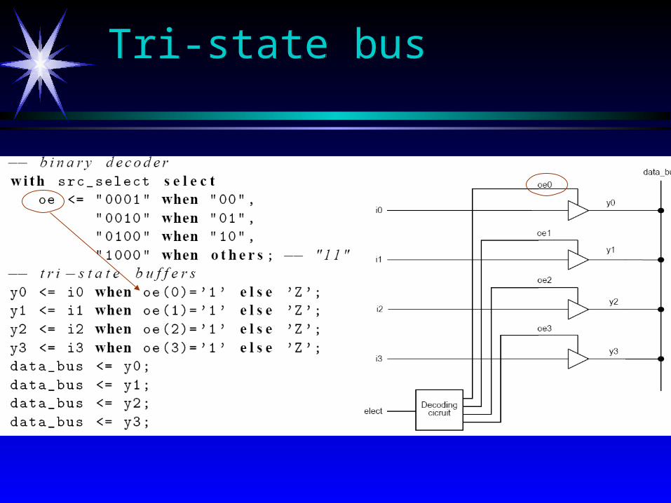
Tri-state busTri-state bus

Problem with tri-state busProblem with tri-state bus Difficult to optimize, verify and test Difficult to optimize, verify and test
Alternative to tri-state bus: muxAlternative to tri-state bus: mux
Tri-state busTri-state bus

Synthesis Entry Points
High-level languageHigh-level language description description E.g., VHDL, VerilogE.g., VHDL, Verilog
Tool-specific languageTool-specific language description description May include parameterizable primitivesMay include parameterizable primitives
Truth tablesTruth tables May be in a form “borrowed” from another May be in a form “borrowed” from another
target technology, such as PLDstarget technology, such as PLDs Logic equationsLogic equations
Common Synthesis Targets
ASICsASICs ““Simple” ASIC development is Simple” ASIC development is greatly simplifiedgreatly simplified Expertise required for aggressive speed, size, or power Expertise required for aggressive speed, size, or power
designsdesigns FPGAsFPGAs
Design can be retargeted to an FPGA for a low-cost Design can be retargeted to an FPGA for a low-cost rapid-turnaround rapid-turnaround prototype prototype to test functionalityto test functionality
Routing and layout problems similar to ASICsRouting and layout problems similar to ASICs PLDsPLDs
Routing and layout largely replaced by design Routing and layout largely replaced by design partitioningpartitioning
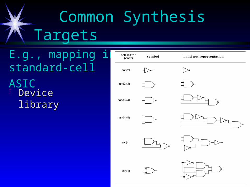
E.g., mapping in
standard-cell ASIC E.g., mapping in
standard-cell ASIC Device libraryDevice library
Common Synthesis Targets
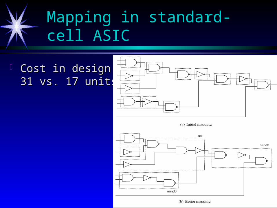
Cost in design area : Cost in design area : 31 vs. 17 units31 vs. 17 units
Mapping in standard-cell ASIC Mapping in standard-cell ASIC

Mapping in FPGAMapping in FPGA
With 5-input LUT (Look-Up-Table) cellsWith 5-input LUT (Look-Up-Table) cells
Synthesis Shortcomings
Design partitioningDesign partitioning A difficultA difficult problem requiring much user interaction problem requiring much user interaction
Circuit timing estimatesCircuit timing estimates High-level synthesis tools use High-level synthesis tools use pre-layout estimatespre-layout estimates
- not accurate for large (e.g. >6000 gates) circuits- not accurate for large (e.g. >6000 gates) circuits May be May be difficult to associatedifficult to associate resulting design resulting design
with original descriptionwith original description
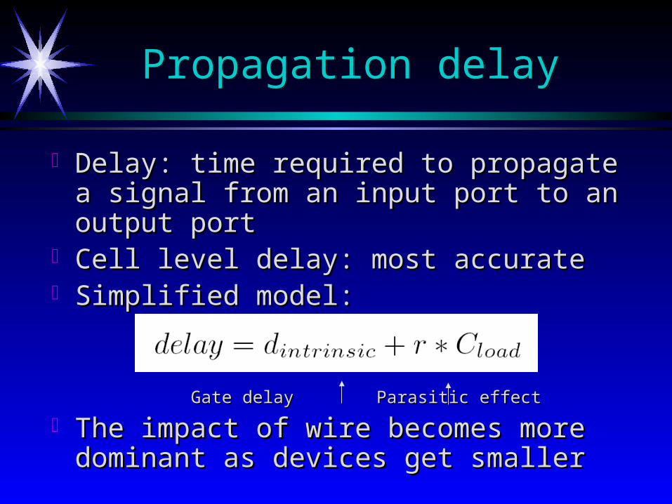
Delay: time required to propagate a signal from Delay: time required to propagate a signal from an input port to an output portan input port to an output port
Cell level delay: most accurateCell level delay: most accurate Simplified model:Simplified model:
Gate delayGate delayParasitic effectParasitic effect
The impact of wire becomes more dominant as The impact of wire becomes more dominant as devices get smallerdevices get smaller
Propagation delayPropagation delay

Propagation delayPropagation delay
i
wigiload CCC
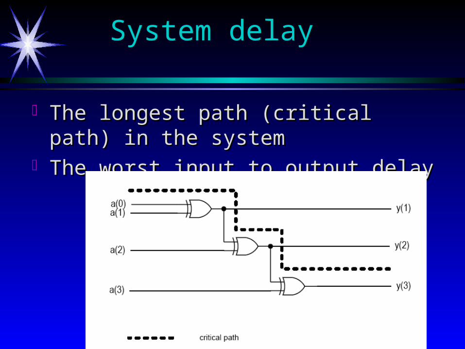
System delay System delay
The longest path (critical path) in the systemThe longest path (critical path) in the system The worst input to output delayThe worst input to output delay
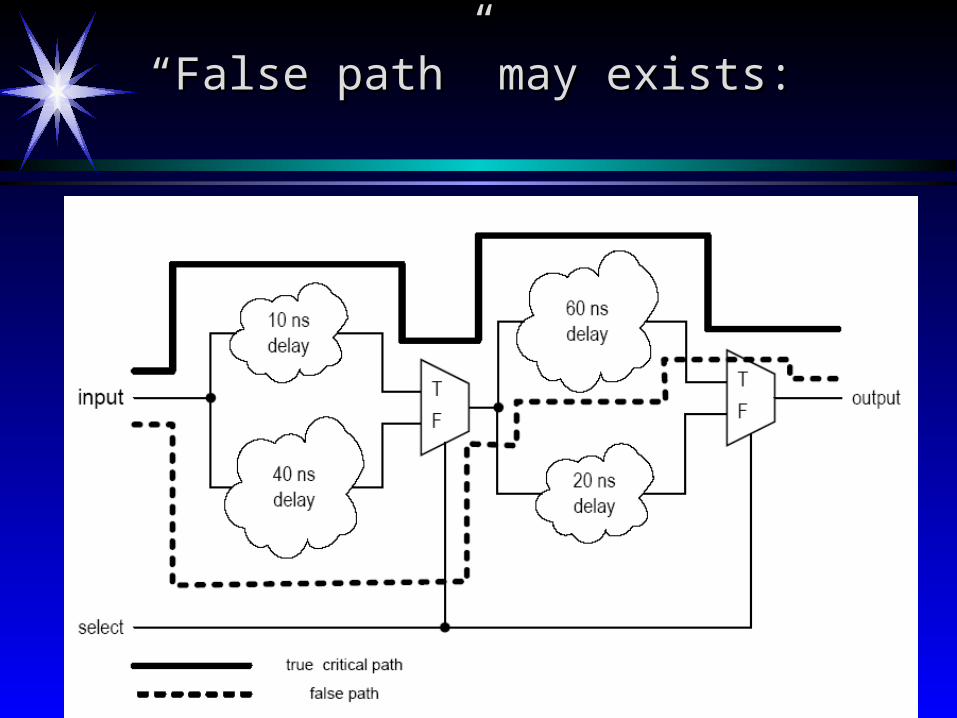
““False path” may exists:False path” may exists:
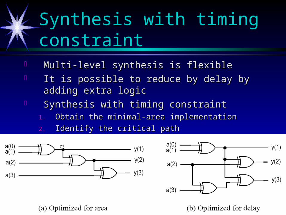
Synthesis with timing constraintSynthesis with timing constraint
Multi-level synthesis is flexibleMulti-level synthesis is flexible It is possible to reduce by delay by adding extra logicIt is possible to reduce by delay by adding extra logic Synthesis with timing constraintSynthesis with timing constraint
1.1. Obtain the minimal-area implementationObtain the minimal-area implementation
2.2. Identify the critical pathIdentify the critical path
3.3. Reduce the delay by adding extra logicReduce the delay by adding extra logic

Area-delay trade-off curveArea-delay trade-off curve
Timing HazardsTiming Hazards
Propagation delay: time to obtain a stable Propagation delay: time to obtain a stable outputoutput
Hazards: the fluctuation occurring during Hazards: the fluctuation occurring during the transient period the transient period Static hazard: glitch when the signal should be Static hazard: glitch when the signal should be
stablestable Dynamic hazard: a glitch in transitionDynamic hazard: a glitch in transition
Due to the multiple converging paths of an Due to the multiple converging paths of an output port output port
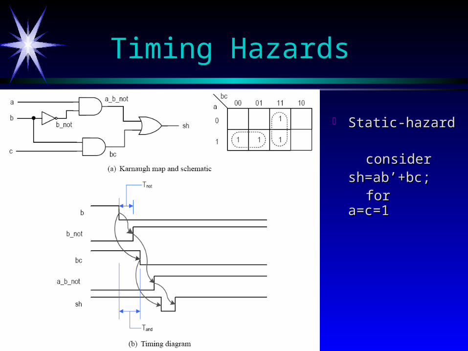
Static-hazardStatic-hazard
considerconsidersh=ab’+bc;sh=ab’+bc;
for a=c=1for a=c=1
Timing HazardsTiming Hazards
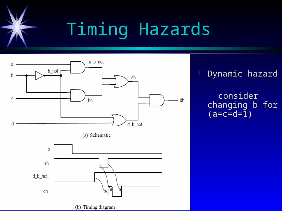
Dynamic hazard Dynamic hazard consider changing consider changing
b for (a=c=d=1)b for (a=c=d=1)
Timing HazardsTiming Hazards

Dealing with hazardsDealing with hazards
Some hazards can be eliminated in theory Some hazards can be eliminated in theory
Eliminating glitches is very difficult in reality, Eliminating glitches is very difficult in reality, and almost impossible for synthesisand almost impossible for synthesis
Multiple inputs can change simultaneouslyMultiple inputs can change simultaneously e.g., 1111=>0000 in a countere.g., 1111=>0000 in a counter
How to deal with it? How to deal with it? Ignore glitches in the transient period and retrieve Ignore glitches in the transient period and retrieve
the data after the signal is stabilizedthe data after the signal is stabilized
Dealing with hazardsDealing with hazards
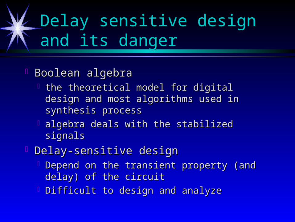
Delay sensitive design and its dangerDelay sensitive design and its danger
Boolean algebra Boolean algebra the theoretical model for digital design and the theoretical model for digital design and
most algorithms used in synthesis processmost algorithms used in synthesis process algebra deals with the stabilized signalsalgebra deals with the stabilized signals
Delay-sensitive design Delay-sensitive design Depend on the transient property (and delay) of Depend on the transient property (and delay) of
the circuitthe circuit Difficult to design and analyzeDifficult to design and analyze
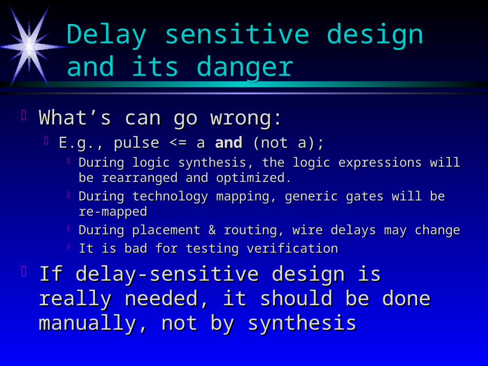
What’s can go wrong:What’s can go wrong: E.g., pulse <= a E.g., pulse <= a andand (not a); (not a);
During logic synthesis, the logic expressions will be rearranged and During logic synthesis, the logic expressions will be rearranged and optimized.optimized.
During technology mapping, generic gates will be re-mappedDuring technology mapping, generic gates will be re-mapped During placement & routing, wire delays may changeDuring placement & routing, wire delays may change It is bad for testing verificationIt is bad for testing verification
If delay-sensitive design is really needed, it If delay-sensitive design is really needed, it should be done manually, not by synthesisshould be done manually, not by synthesis
Delay sensitive design and its dangerDelay sensitive design and its danger

Hardware Synthesis Flow
MulticomponentPartitioning
Integration
MultichipSynthesisSystem(MSS)
ASICSynthesis
(DSS)
FPGASynthesis
ProceduralSpecification of
Hardware inVHDL
Constrains
TargetArchitecture
BehavioralSpecifications
and Constraintsfor MCMs
BehavioralSpecifications
and Constraintsfor FPGAs
BehavioralSpecifications
and Constraintsfor ASICs
TechnologyDatabase