harmonic driveactuator 7-14 group companies harmonic drive systems, inc. 6-25-3 minami-ohi,...
TRANSCRIPT

FHA Mini Servo Actuator24V Motor Winding
Total Motion Control
Harmonic Drive®actuatorP r e c i s i o n G e a r i n g & M o t i o n C o n t r o l
2
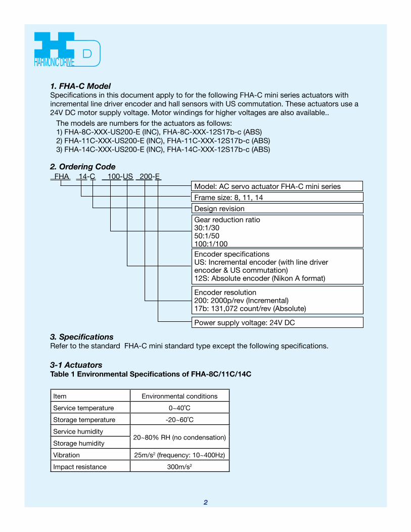
Model: AC servo actuator FHA-C mini series Frame size: 8, 11, 14 Design revision Gear reduction ratio 30:1/30 50:1/50 100:1/100 Encoder specifications US: Incremental encoder (with line driver encoder & US commutation) 12S: Absolute encoder (Nikon A format)
Encoder resolution 200: 2000p/rev (Incremental) 17b: 131,072 count/rev (Absolute)
Power supply voltage: 24V DC
3. Specifications Refer to the standard FHA-C mini standard type except the following specifications.
3-1 Actuators Table 1 Environmental Specifications of FHA-8C/11C/14C
Item Environmental conditionsService temperature 0~40˚CStorage temperature -20~60˚CService humidity
20~80% RH (no condensation)Storage humidityVibration 25m/s2 (frequency: 10~400Hz)Impact resistance 300m/s2
1. FHA-C Model Specifications in this document apply to for the following FHA-C mini series actuators with incremental line driver encoder and hall sensors with US commutation. These actuators use a 24V DC motor supply voltage. Motor windings for higher voltages are also available..
The models are numbers for the actuators as follows: 1) FHA-8C-XXX-US200-E (INC), FHA-8C-XXX-12S17b-c (ABS) 2) FHA-11C-XXX-US200-E (INC), FHA-11C-XXX-12S17b-c (ABS) 3) FHA-14C-XXX-US200-E (INC), FHA-14C-XXX-12S17b-c (ABS)
2. Ordering CodeFHA 14-C 100-US 200-E
3
Model ratio
Item
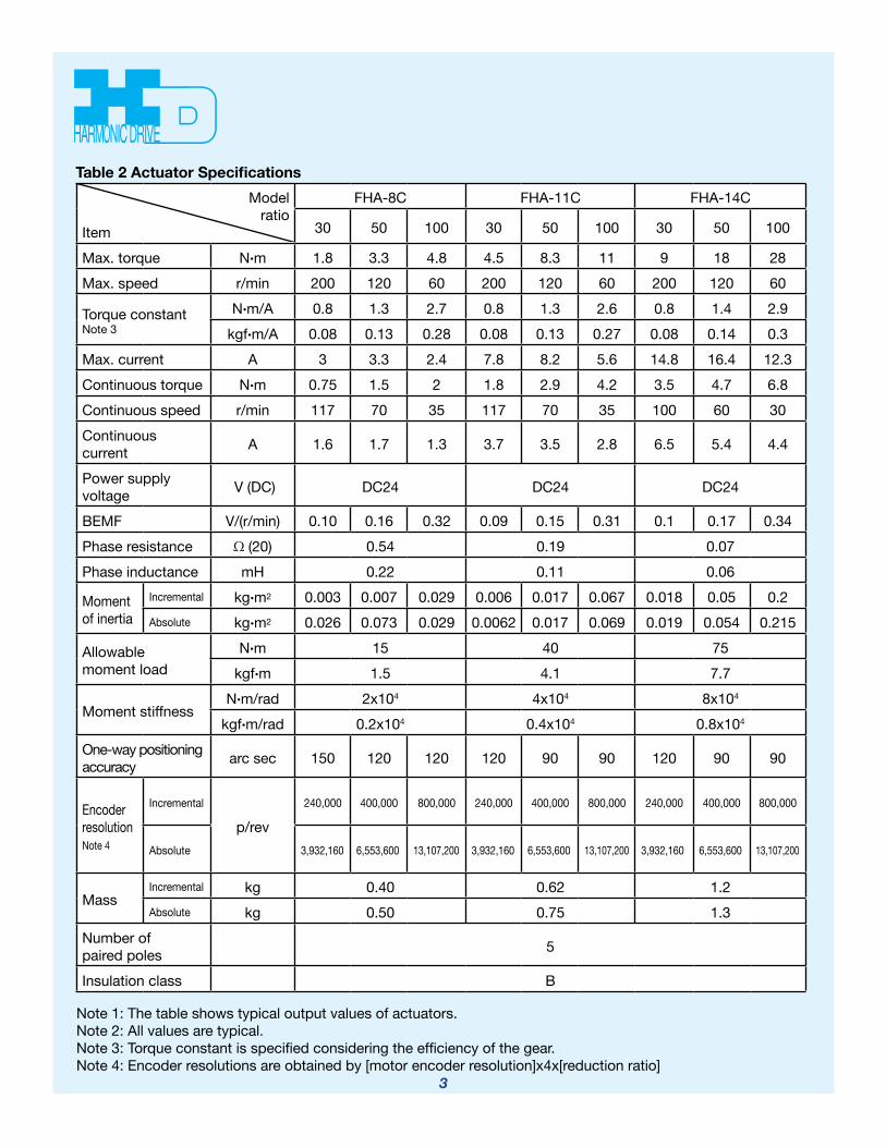
FHA-8C FHA-11C FHA-14C
30 50 100 30 50 100 30 50 100
Max. torque N•m 1.8 3.3 4.8 4.5 8.3 11 9 18 28Max. speed r/min 200 120 60 200 120 60 200 120 60
Torque constant Note 3
N•m/A 0.8 1.3 2.7 0.8 1.3 2.6 0.8 1.4 2.9kgf•m/A 0.08 0.13 0.28 0.08 0.13 0.27 0.08 0.14 0.3
Max. current A 3 3.3 2.4 7.8 8.2 5.6 14.8 16.4 12.3Continuous torque N•m 0.75 1.5 2 1.8 2.9 4.2 3.5 4.7 6.8Continuous speed r/min 117 70 35 117 70 35 100 60 30Continuous current A 1.6 1.7 1.3 3.7 3.5 2.8 6.5 5.4 4.4
Power supply voltage V (DC) DC24 DC24 DC24
BEMF V/(r/min) 0.10 0.16 0.32 0.09 0.15 0.31 0.1 0.17 0.34Phase resistance (20) 0.54 0.19 0.07Phase inductance mH 0.22 0.11 0.06
Moment of inertia
Incremental kg•m2 0.003 0.007 0.029 0.006 0.017 0.067 0.018 0.05 0.2Absolute kg•m2 0.026 0.073 0.029 0.0062 0.017 0.069 0.019 0.054 0.215
Allowable moment load
N•m 15 40 75kgf•m 1.5 4.1 7.7
Moment stiffness N•m/rad 2x10⁴ 4x10⁴ 8x10⁴
kgf•m/rad 0.2x10⁴ 0.4x10⁴ 0.8x10⁴
One-way positioning accuracy arc sec 150 120 120 120 90 90 120 90 90
Encoder resolution Note 4
Incremental
p/rev 240,000 400,000 800,000 240,000 400,000 800,000 240,000 400,000 800,000
Absolute 3,932,160 6,553,600 13,107,200 3,932,160 6,553,600 13,107,200 3,932,160 6,553,600 13,107,200
Mass Incremental kg 0.40 0.62 1.2Absolute kg 0.50 0.75 1.3
Number of paired poles 5
Insulation class B
Note 1: The table shows typical output values of actuators. Note 2: All values are typical. Note 3: Torque constant is specified considering the efficiency of the gear. Note 4: Encoder resolutions are obtained by [motor encoder resolution]x4x[reduction ratio]
Table 2 Actuator Specifications

4
Item Unit SpecificationType Incremental, Rectangular wave, line driverOutput signal A,A,B,B,Z,Z,U,U,V,V,W,W
Number of pulseA,B p/rev 2000
U,V,W p/rev 5Z p/rev 1
Power supply voltage V +5VDC ±5%Current consumption Note1 mA 250 maxOutput circuit form Line driver (equivalent to SN75ALS192NS)
Item Unit SpecificationType Absolute
Output signal Serial communication (Nikon A-format equivalent) Communication 4M bps
Pulse Count/rev
Single (motor) turn: 131,072 (17 bit)Multi-turn: 65,536 (16 bit)
Battery back-upPower supply voltage V +5VDC ±5%Current consumption mA 180 max
Table 3-1 Incremental Encoder Specifications
Table 3-2 Absolute Encoder Specifications
3-2 Encoder Specifications
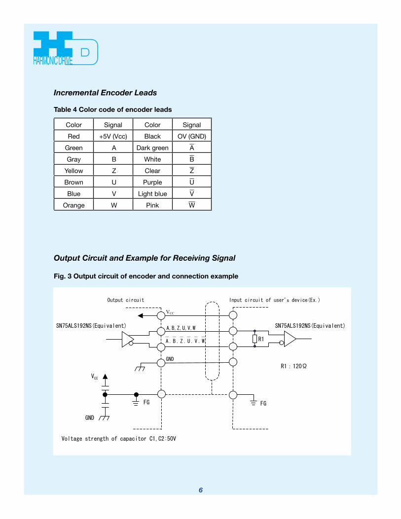
Note 1: When using R1 resistor shown in Fig.3 below
5
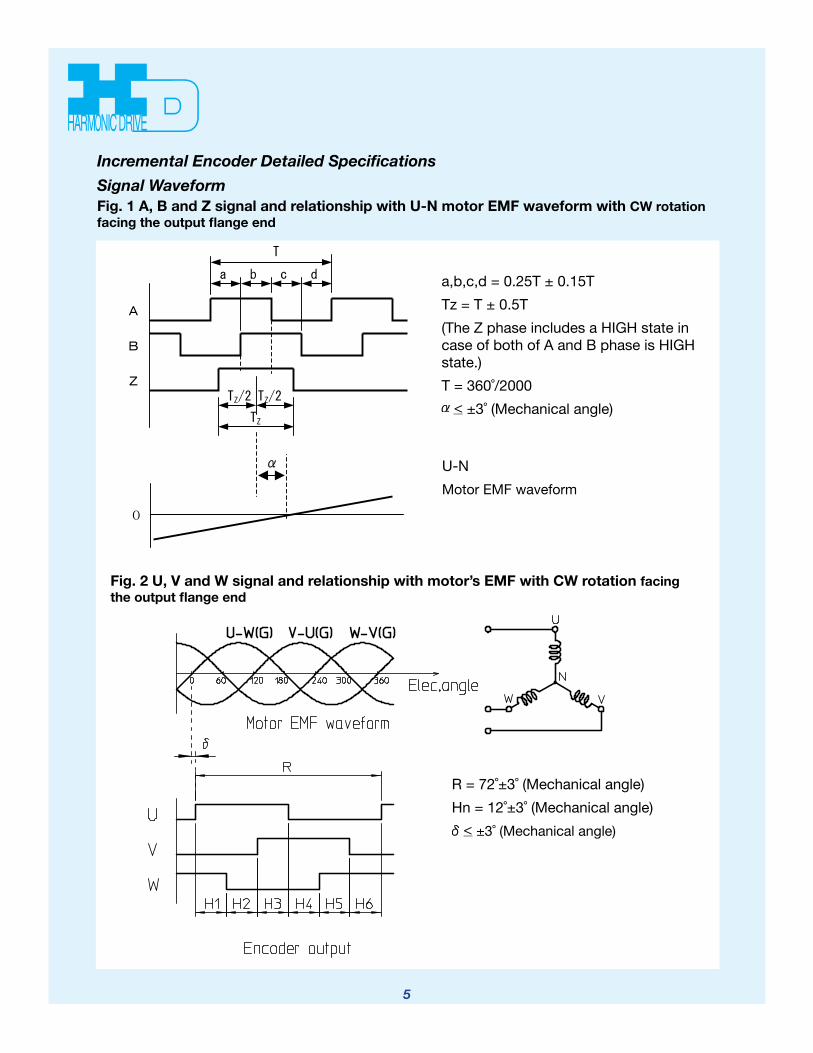
a,b,c,d = 0.25T ± 0.15T Tz = T ± 0.5T (The Z phase includes a HIGH state in case of both of A and B phase is HIGH state.) T = 360˚/2000
< ±3˚ (Mechanical angle)
U-N Motor EMF waveform
Fig. 1 A, B and Z signal and relationship with U-N motor EMF waveform with CW rotation facing the output flange end
R = 72˚±3˚ (Mechanical angle) Hn = 12˚±3˚ (Mechanical angle) < ±3˚ (Mechanical angle)
Fig. 2 U, V and W signal and relationship with motor’s EMF with CW rotation facing the output flange end
Incremental Encoder Detailed Specifications Signal Waveform
6
Color Signal Color Signal Red +5V (Vcc) Black OV (GND)
Green A Dark green AGray B White B
Yellow Z Clear ZBrown U Purple UBlue V Light blue V
Orange W Pink W
Incremental Encoder Leads
Table 4 Color code of encoder leads
Output Circuit and Example for Receiving Signal
Fig. 3 Output circuit of encoder and connection example

7
4External Dimensions of FHA-C Mini Actuators with Incremental Encoder
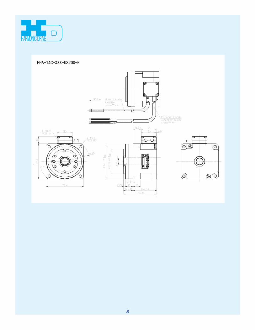
8
9
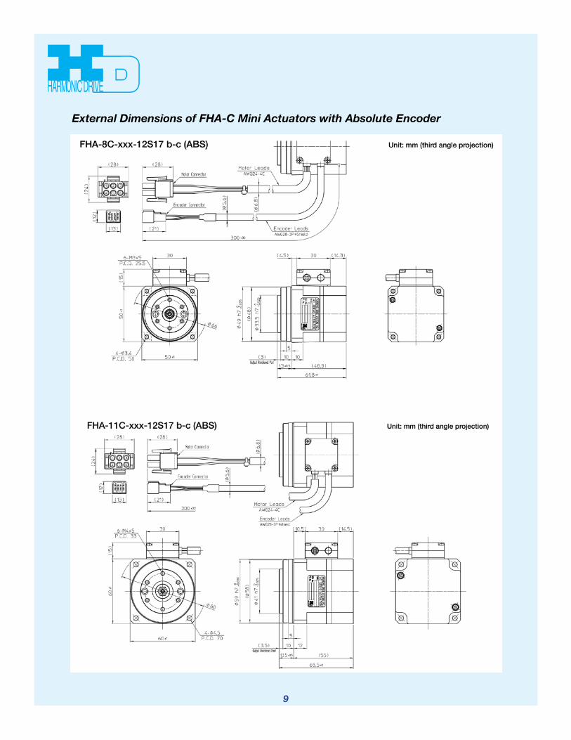
External Dimensions of FHA-C Mini Actuators with Absolute Encoder

10
Contact an application engineer at Harmonic Drive LLC for more information on our matched servo drivers for use with FHA-C actuators.

Notes:

Rev 7-14
Group Companies Harmonic Drive Systems, Inc. 6-25-3 Minami-Ohi, Shinagawa-ku Tokyo 141-0013, Japan
Harmonic Drive AG Hoenbergstrasse, 14, D-6555 Limburg/Lahn Germany
Harmonic Drive is a registered trademark of Harmonic Drive LLC.
Harmonic Drive LLCBoston US Headquarters247 Lynnfield Street Peabody, MA 01960
New York Sales Office100 Motor ParkwaySuite 116Hauppauge, NY 11788
California Sales Office333 W. San Carlos Street Suite 1070San Jose, CA 95110
Chicago Sales Office137 N. Oak Park Ave., Suite 410Oak Park, IL 60301
T: 800.921.3332 T: 978.532.1800 F: 978.532.9406
www.HarmonicDrive.net