heavy duty stair lift system installation and … is imperative that this manual be read and...
TRANSCRIPT
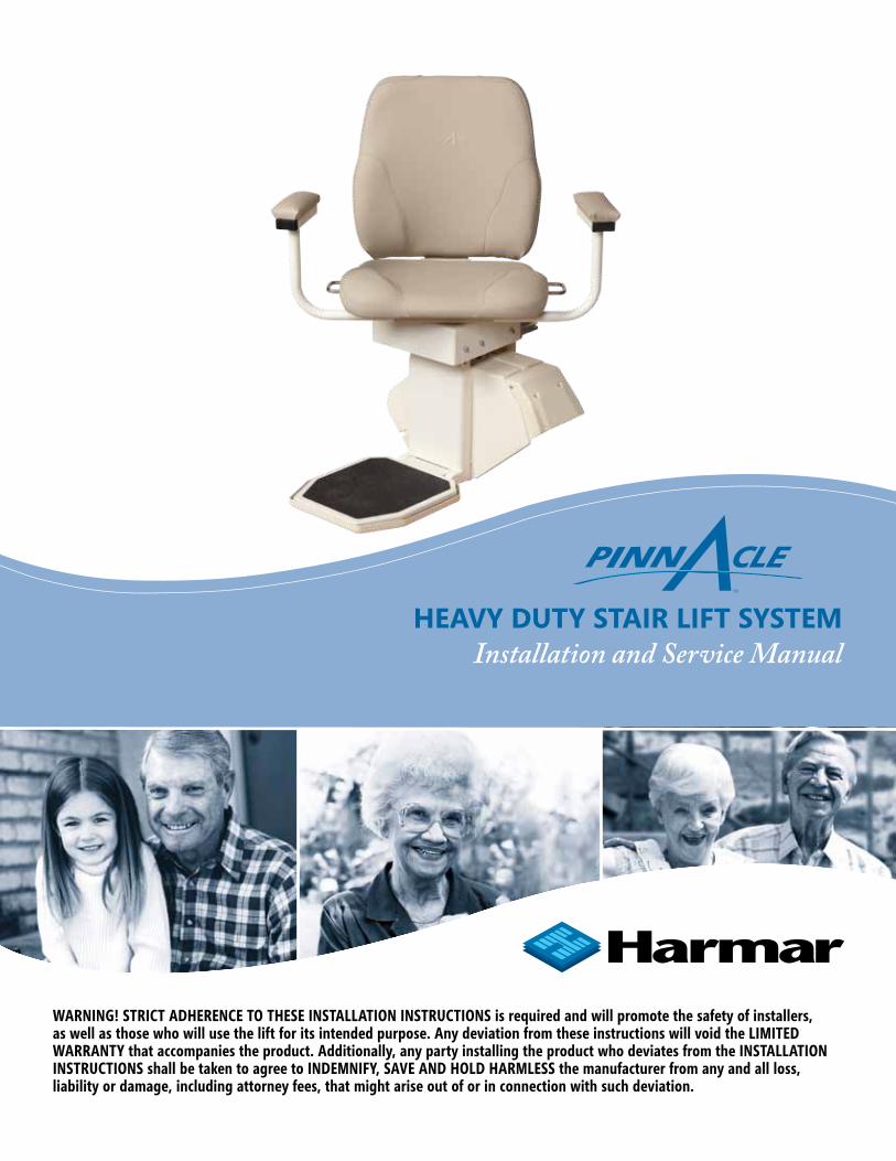
HEAVY DUTY STAir LifT SYSTEmInstallation and Service Manual
WARNING! STRICT ADHERENCE TO THESE INSTALLATION INSTRUCTIONS is required and will promote the safety of installers, as well as those who will use the lift for its intended purpose. Any deviation from these instructions will void the LIMITED WARRANTY that accompanies the product. Additionally, any party installing the product who deviates from the INSTALLATION INSTRUCTIONS shall be taken to agree to INDEMNIFY, SAVE AND HOLD HARMLESS the manufacturer from any and all loss, liability or damage, including attorney fees, that might arise out of or in connection with such deviation.

Pinnacle HD Stair Lift Manual | | www.Harmar.com | 866-351-27762
Table of ContentsTable of Contents
Read and understand this manual prior to attempting stair lift installations. Please refer to the Owner’s Manual for Limited Warranty information and operating instructions. The Owner’s Manual must be given to the owner of the lift before it is put into service.
Any alterations to the equipment without written authorization by the manufacturer may void the warranty.Harmar lifts are designed to require as little assembly by the installer as possible. If you have questions, concerns or comments, please contact Harmar’s Technical Service Department at 1-866-378-6848 or [email protected].
CONTENTS:
Important! It is imperative that this manual be read and understood prior to attempting installation of the stair lift. Please observe all cautions and warnings in this manual, and on equipment labels.
I. PRELIMINARY CHECKS ................................................................3 A. Tools required ..............................................................3 B. Included parts...............................................................3 II. INSTALLATION PROCEDURES ....................................................4 A. Determine rail length...................................................4 B. Rail installation..........................................................5-6 C. Chassis installation.......................................................7 D. Final rail installation.....................................................8 E. Footrest and seat installation................................9-12 III. REMOTE CALL/SEND CONTROL OPERATION.......................13 A. Remote control operation.........................................13 B. Remote control reprogramming..............................13 IV. COMPLETION PROCEDURES ...................................................14 A. Test armrest control switch.......................................14 B. Tighten brackets.........................................................14 C. Set upper and lower travel limits............................14 D. Test safety stop switches..........................................15 E. Additional System Checks.........................................16

866-351-2776 | www.Harmar.com | | Pinnacle HD Stair Lift Manual 3
Table of ContentsTable of Contents
I. PRELIMINARY CHECKS TOOLS REQUIRED
The following is a suggested list of basic tools to have on hand during installation. Cordless drill Allen wrench (5/64”, 5/32”, 3/16”, 5/16”) Nut driver (3/8” and 5/16”) 6-10” driver extension T30 Torx bit (included) Level Hack saw or chop saw SAE socket set SAE wrenches Tape measure
INCLUDED PARTSBefore beginning installation, inspect and check the box contents. Report any damage to your dealer. Chassis Box: Rail Box:
• Chassis • Bottomrailpre-installedwith:• Call/sendparts •Bottomendplate •2Call/sendhandcontrols •Chargestripwireharness• Batterycharger •Bottomlimitcam• InstallationManual •Jointpinsandjointbrackets• Owner’s Manual (two-piece rail only)
•Plasticgearrack •Toprailpre-installedwith: •ChargestripwireharnessRailBracketBox: •Railaccessories(plasticbag):
• Railbrackets(2,3,4,or6perset) •Topendplate• Woodscrews(#14X2”(4perrailbracket) •Compressionbolts(3sizes) •Self-cuttingscrews(1/4”-20X1”)
ChairBox: •TorxT30driverbit •Chair •Railparts(plasticbag): •BackRest •Extraplasticracks(2or3)•SeatBelt •ToplimitcamFootrest Box:•Footrestcompletewith: •SwivelSlideRails •SwivelPinbracket• RearSeatSupport
Preliminary Checks

Pinnacle HD Stair Lift Manual | | www.Harmar.com | 866-351-27764
Table of Contentsinstallation Procedures
II. INSTALLATION PROCEDURES
A. DETERMINE OVERALL RAIL LENGTH (Only if track did not come pre-cut to length)
Step 1: Determine obstructions that will affect the position and length of the rail, such as walls, doors, hallway orientation, etc.
Step 2: Measuretheoveralllengthofthestairsfromthenoseatthetoplandingtothefloor(nosetofloormeasurement, e.g., 128”, see image below).
Step 3: Foranormalstairwaywithadequatelandingspace,add13”tothenosetofloormeasurement.Thiswillprovideenoughraillengthtoallowthestairlifttobeadjustedsothatthefloor-to-seatheightwillbethesameatboth the top and bottom (e.g., 141”).
Step 4: If the top landing has restrictions (i.e., a wall or doorway), use the chart below to determine the length of extension needed.
Step 5: To cut the rail, use a standard 12” chop saw, with a blade designed to cut aluminum. Do not cut rail inside the house (aluminum chips are very hard to remove from carpets).
TiP! DO NOT cut the end of the rail that contains the joint holes. Remove the charger strips and wire harness before cutting.
Extension
7” 9” 11” 13”
3.9” 5” 6.1” 7.2”
Horizontal intrusion on top landing

866-351-2776 | www.Harmar.com | | Pinnacle HD Stair Lift Manual 5
Table of Contentsinstallation Procedures
B. RAIL INSTALLATION
Step 1: Open the rail box and remove the contents.
Step 2: Position the bottom rail (with end plate attached) directly on the stairs with the end plate towards the bottom of the stairs and the plastic rack facing up. Place an objectthatmeasuresbetween3/4”and1”betweenendplateandthefloor.
Step 3: Position the two ends of the track close together. Locate and connect the plug on the ends of the two charger harnesses inside the two track pieces.
Step 4: With the plastic rack facing up, slide the top rail into the bottom rail and guide them together using the pre-installed pins. Gently tap the top rail if necessary to get them close together. Be cautious not to pinch the charger harness.
Step 5: Installtwo(2)jointfastenersandfirmlytightenwith3/16”Allenwrench.Thensliderackpiecesdowntocoverjoint.
Step 6: Turnoverjoinedrailsandinstalltheremainingtwo(2)jointfastenersandfirmlytightenwith3/16”Allenwrench.Thensliderackpiecesdowntocoverjoint.
TiP! Use the chair box or another heavy object, like a toolbox, at the bottom to prevent the rail from sliding down the stairs.
Pinnacle HD Stair Lift Manual | | www.Harmar.com | 866-351-27766
Table of Contents
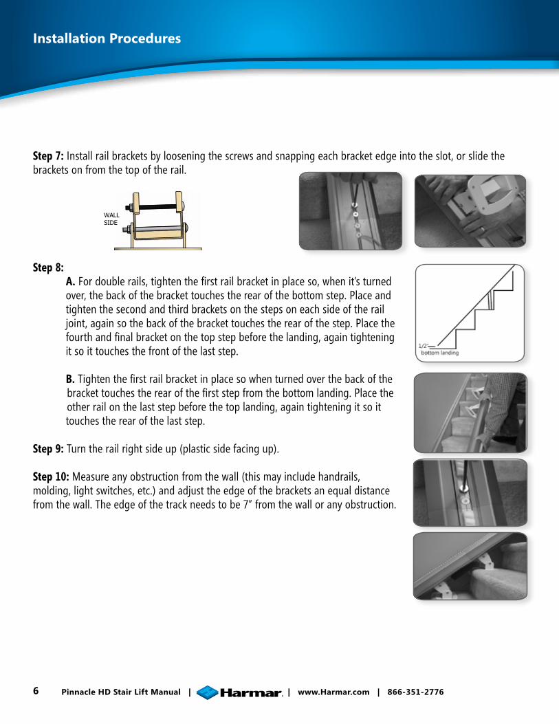
Step 7: Install rail brackets by loosening the screws and snapping each bracket edge into the slot, or slide the brackets on from the top of the rail.
Step 8: A.Fordoublerails,tightenthefirstrailbracketinplaceso,whenit’sturned over, the back of the bracket touches the rear of the bottom step. Place and tighten the second and third brackets on the steps on each side of the rail joint,againsothebackofthebrackettouchestherearofthestep.Placethe fourthandfinalbracketonthetopstepbeforethelanding,againtightening it so it touches the front of the last step. B.Tightenthefirstrailbracketinplacesowhenturnedoverthebackofthe brackettouchestherearofthefirststepfromthebottomlanding.Placethe other rail on the last step before the top landing, again tightening it so it touches the rear of the last step.
Step 9: Turn the rail right side up (plastic side facing up).
Step 10: Measure any obstruction from the wall (this may include handrails, molding,lightswitches,etc.)andadjusttheedgeofthebracketsanequaldistancefrom the wall. The edge of the track needs to be 7” from the wall or any obstruction.
installation Procedures
WALLSIDE
866-351-2776 | www.Harmar.com | | Pinnacle HD Stair Lift Manual 7
Table of Contentsinstallation Procedures
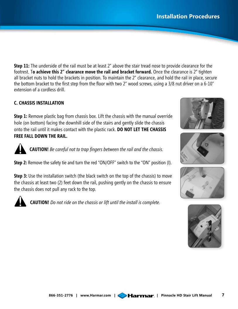
Step 11: The underside of the rail must be at least 2” above the stair tread nose to provide clearance for the footrest. To achieve this 2” clearance move the rail and bracket forward. Once the clearance is 2” tighten all bracket nuts to hold the brackets in position. To maintain the 2” clearance, and hold the rail in place, secure thebottombrackettothefirststepfromthefloorwithtwo2”woodscrews,usinga3/8nutdriverona6-10”extension of a cordless drill.
C. CHASSIS INSTALLATION
Step 1: Remove plastic bag from chassis box. Lift the chassis with the manual override hole (on bottom) facing the downhill side of the stairs and gently slide the chassis onto the rail until it makes contact with the plastic rack. DO NOT LET THE CHASSIS FREE FALL DOWN THE RAIL.
CAUTION! Be careful not to trap fingers between the rail and the chassis.
Step 2: Remove the safety tie and turn the red “ON/OFF” switch to the “ON” position (I).
Step 3: Use the installation switch (the black switch on the top of the chassis) to move the chassis at least two (2) feet down the rail, pushing gently on the chassis to ensure the chassis does not pull any rack to the top.
CAUTION! Do not ride on the chassis or lift until the install is complete.

Pinnacle HD Stair Lift Manual | | www.Harmar.com | 866-351-27768
installation Procedures
D. FINAL RAIL INSTALLATION
Step 1: Install the remaining plastic rack pieces in the upper rail.
Step 2: Useahacksaworchopsawtocutthelastplasticrackpieceflushwith therailend.Placesomethingonthefloortocatchdebrisormarkandcutthe rack outside.
The exposed, cut end of the plastic rack should face the top end of the rail (the factory-cut side should butt against the lower rack).
Step 3: Slide the top limit cam into one of the cam slots (either side), and tighten the pre-inserted Allen screw with a 5/64” Allen wrench. This will beusedtosetthefinalupperlimitsforthestairlift.
Step 4: Remove charging strip from the rail box. Connect charging strip connector to the charger wire that runs through the center of the rail from the lower charging strips.
Insert the two (2) charger strips into the keyed slots at the top of the rail (while standing on the top landing looking down). The charging strip with the red wire should be inserted into the left slot with the metal strip facing out. The charging strip with the black wire should be inserted into the right slot with the metal strip pointing out.
Bend the red and black wire tabs in toward the center of the rack.
Insert excess cable into the rail, leaving the pigtail with the Molex connector.
Step 5: Install the end plate to the top of the rack with the four (4) self-cutting Torx screws using the supplied T30 Torx bit.
TiP! Too much torque applied to these screws may result in damage. Take your time and apply grease to threads.

866-351-2776 | www.Harmar.com | | Pinnacle HD Stair Lift Manual 9
Table of Contentsinstallation Procedures
Step 6: Install one of the rack pre-compression screws in the threaded hole in the top railplate;tightenasfirmlyaspossiblebyhandwitha5/32”Allenwrench.
There are three (3) kinds of pre-compression screws:1. 1/2” for tracks under 6’2. 3/4” for tracks between 6’ and 12’3. 1” for tracks over 12’
Step 7: Plug in the battery charger at either end of the rail, choosing the closest or most convenient location of a wall power supply. Minimize wire length and intrusion.
E. FOOTREST & SEAT INSTALLATION
Step 1: Remove footrest from box and use the installation switch to drive the chassis downwardtoapositionabout6”clearofthefloor.Thisprovidesasafeareatoinstallandadjustthefootrest.Donotdrivetheunitintobottomstop.
Step 2: Turn the red “ON/OFF” switch located on the top of the chassis to the “OFF” position (0).
Step 3: Position the footrest onto the two (2) seat-leveling bolts on the outside of the chassis by aligning the large opening at the slot ends of the footrest.
Step 4: Ensure the footrest is fully engaged.

Pinnacle HD Stair Lift Manual | | www.Harmar.com | 866-351-277610
Table of Contentsinstallation Procedures
Step 5: Position the rear seat support onto the two (2) seat-leveling bolts on the backside of the chassis by aligning the large opening at the slot ends of the footrest.
Secure the rear seat support to the footrest/seat support using the two (2) hex-head bolts and washers.
Secure the rear of the slider rails to the rear seat support using the two (2) socket bolts.
Ensure that the seat support is level and tighten the two (2) front and two (2) rear leveling bolts.
Step 6: Connect the footrest cable to the 6-pin connector on the chassis.
TiP! When the 6-pin footrest and the 8-pin chair cables are both connected to the chas-sis, the black installation switch on the chassis is disabled and will not function.

866-351-2776 | www.Harmar.com | | Pinnacle HD Stair Lift Manual 11
Table of Contentsinstallation Procedures
Step 7: Align the seat rollers with the slider rails and slide the seat half way back.
Step 8: Swivel seat approximately 45 degrees to one side.
Step 9: Attachtheswivelpinbracketwiththeflatsidetowardsthefootrest support using the two (2) hex head bolts and washers. Ensure that one of the swivel pins is engaged into the slot in the swivel cam.
Step 10: Connect the seat cable to the 8-pin connector on the chassis.

Pinnacle HD Stair Lift Manual | | www.Harmar.com | 866-351-277612
Step 11: If the lift is equipped with the optional key lock, ensure that the key switch on the armrest control is in the locked position; the key should be in the vertical position.
Step 12: Turn the red “ON/OFF” switch located on the top of the chassis to the “ON” (I) position. You should hear a single beep and the LED indicator light on the armrest control should cycle through a test sequence, showing red, yellow and green respectively. If any of the system controls or safety sensors are engaged the LED indicator light will turn to yellow.
Step 13: If the LED indicator light is not green, check the safety senors:
1. Seat swivel sensor (seat should be in the locked position)
2. Footrest lower sensor (check by pushing in on the safety pan on the footrest)
3. Upper foot pan safety sensor (check by pushing on the safety pan on the footrest).
4. Front foot pan safety sensor (check by pushing on the safety pan on the footrest).
5. Uphill safety sensor (ensure nothing is blocking upward passage)
6. Downhill safety sensor (ensure nothing is blocking downward passage)
If the LED indicator light is still not green after testing sensors, turn the unit off and recheck all wire plugs. Turn the unit on again and recheck the LED indicator light cycle. When the LED indicator light remains green the lift is ready to operate.
Table of Contentsinstallation Procedures

866-351-2776 | www.Harmar.com | | Pinnacle HD Stair Lift Manual 13
remote Call/Send Control Operation
III. REMOTE CALL/SEND CONTROL OPERATION
A. REMOTE CONTROL OPERATION
The key switch on the arm of the chair must be in the “ON” position to use the remote call/send control.
STEP 1: Press and hold the appropriate directional button on the front of the hand control. The LED indicator light will turn green when a signal is being sent.
The chair lift will operate with or without a rider. All safety sensors on the chair lift are designed to continue to operate in their normal mode. The LED light indicator on the armrest will also display the appropriate color.
STEP 2: If the chair lift fails to respond, this may indicate the batteries are discharged and need to be replaced. Remove the back cover of the control and replace with commonly-available AAA batteries, ensuring that the polarity is correct.
B. REMOTE CONTROL RE-PROGRAMMING
All call/send controls are factory programmed. Re-programming is not normally necessary during installation.In the event that the remote call/send control needs to be re-programmed, it is essential to program BOTH controls in one programming cycle. Do so by completing the following:
1. Start with the red “ON/OFF” switch in the “OFF” position (0).2. Disconnect the 6-pin footrest and 8-pin chair wire harnesses from the chassis.3. Press and hold the install switch (located on the top of the chassis) in either direction.4. Turn the red “ON/OFF” switch to the “ON” position (I), and then release the install switch.5. Theliftwillbegintobeeprapidly(thismeansthefirstremotecontrolisreadytoprogram).6. Pressandreleasethe“UP”or“DOWN”buttonofthefirstremotecontrol(thefirstremotecontrolisnow
programmed).7. Press and release the “UP” or “DOWN” button of the second remote control (the second remote control is now
programmed).8. Upon completion, two beeps will indicate that both remote controls have been programmed. 9. Turn the “ON/OFF” switch to the “OFF” position (0).10. Connect the 6-pin footrest and 8-pin chair wire harnesses to the chassis and then turn the red “ON/OFF” switch to
the “ON” position (I).
11. Test each remote control in both the up and down directions.

Pinnacle HD Stair Lift Manual | | www.Harmar.com | 866-351-277614
Completion Procedures
IV. COMPLETION PROCEDURES
A. TEST ARMREST CONTROL SWITCH
STEP 1: Ensure that the unit travels correctly by operating the armrest control switch while standing in front of the unit.
STEP 2: Depress the switch in the upstairs direction to move up. The lift will beep, wait three (3) seconds and begin to smoothly accelerate upwards. The lift will continue to move upwards as long as the switch is depressed.
STEP 3: Release the switch and the lift will come to an immediate stop.
STEP 4: Depress the switch in the downstairs direction to move down. The lift will beep, wait three (3) seconds and begin to smoothly accelerate downwards.
STEP 5: Release the switch and the lift will come to an immediate stop.
STEP 6: Run the chair all the way up and down the rail to ensure that the top of the seat back has at least a 1/2” clearance from the wall and any obstructions.
CAUTION! Do not ride on the chassis or lift until the install is complete.
B. TIGHTEN BRACKETS
STEP 1: Install and fully tighten the rail bracket mounting screws (four (4) screws per bracket). For hardwood stairs,drillapilotholefirst.Forplywoodorparticleboardstairs,takecaretopreventstripping.
C. SET UPPER AND LOWER TRAVEL LIMITS
STEP 1: Test the lower travel limit by operating the lift downward, keeping the switch depressed. The unit should begintodecelerateabout3”fromitsfinalrestingpositionandstopclearofthefloor.
STEP 2:Thefinalstoppedpositioncanbeadjustedtoaccommodatetheheightoftheuserbyrepositioningthelimit cam located in a slot in the rail.
STEP 3: Usea5/64”Allenwrenchtoloosenthesetscrewinthelimitcam.Adjustthelimitcamupordownandretighten the set screws. Repeat the above steps until the lift stops in the desired position.

866-351-2776 | www.Harmar.com | | Pinnacle HD Stair Lift Manual 15
Completion Procedures
STEP 4: Repeat the above steps to set the upper limits. For safety, the footrest should be set at least level with the upper landing.
STEP 5:Theoptimumpositionismetwhentheseatheightabovetheflooristhesameatthetopandbottomofthestairs.
D. TEST SAFETY STOP SWITCHES
STEP 1: Safety stop switches are located in both the upward and downward ends of the chassis providing protection from obstructions on the rail.
STEP 2: Safety stop switches are located in the footrest bottom pan providing protection from obstructions and trapping hazards on the stairs.
STEP 3: A safety stop switch is part of the swivel seat mechanism and prevents the lift from operating when the swivel is in use.
STEP 4: Test all the safety stop switches by driving the lift down and touching the downward end of the chassis, the lower edge of the footrest, and the underside of the footrest in both its folded and unfolded positions.
STEP 5: In each of the above cases the unit should come to an immediate halt. The LED indicator light on the armrest control should turn to orange and the unit should beep intermittently.
STEP 6: When the control switch is released, the unit should NOT be able to be driven in the direction that the lift initially engaged the obstacle. Test this condition.
STEP 7: Test to ensure that the lift can only be driven away from the obstruction. The LED indicator light will turn to green and stop beeping indicating a safe operating condition.
STEP 8: Repeat the above tests while driving the lift in opposite direction.
STEP 9: If any safety condition does not function properly, carefully review all installation instructions, reset the “ON /OFF” switch and check that the LED indicator light is green. Repeat the above tests.
STEP 10: If any safety stop switch fails to immediately stop the lift and/or a red LED indicator light appears, remove the key to prevent further use of the lift and immediately call the manufacturer for assistance in diagnosing and repairing the problem. DO NOT USE THE LIFT.

Pinnacle HD Stair Lift Manual | | www.Harmar.com | 866-351-277616
Completion Procedures
E. ADDITIONAL SYSTEM CHECKS
STEP 1: After the successful testing of all safety switches, sit on the lift and operate to the top of the stairs. Keeping the control switch depressed continuously, the lift should gently decelerate and then stop at the top of the track.
STEP 2:Asafinaladjustment,sitontheliftanddotwo(2)completeuptripsandstopwiththechairatthebottom. Then tighten the compression screw in the top end plate, then run the chair to the top and again tighten thecompressionscrew.Runthechairtothemiddleanddoafinaltighteningofthecompressionscrew.
STEP 3: Drive the lift to the bottom, keeping the control switch depressed all the time, and check that the lift gently deceleratesandstopssothefootrestpanisclearofthefloor.Ifnecessaryadjustthelimitcamswitha5/64”Allenwrench.
STEP 4: Move the lift about three (3) feet from either the top or bottom of the rail. After 30 seconds the armrest LED indicator light will show orange and beep indicating that the lift is not positioned on a charge point. The beepwillstopafter30seconds,butthearmrestLEDindicatorlightwillcontinuetoflashorange.
STEP 5: Test the seat swivel at the top by using the levers and swiveling the seat towards the landing and stop the seat at 35 and 85 degrees. The seat swivel levers will release into a locked position at each of these angles. The lift will not operate in any of these positions if the control switch is depressed, and the LED indicator light will turn orange. Return the seat to its normal position and the LED indicator light will turn green and the lift will now operate normally.
STEP 6: Drive to the top or bottom and check the battery charging light. If the light is orange or red, the batteries are being charged.
THE LIFT IS NOW READY FOR USE.
© 2012 Harmar MKT-IM-PINNACLEHD-10/15/2012