hg3 instruction manual final - tru hone instruction... · 2018-03-13 · fig. 4 control box...
TRANSCRIPT

HG3 HOLLOW GRINDERInstruction Manual

The Lord is my shepherd, I shall lack nothing.
He makes me lie down in green pastures,
he leads me beside quiet waters, he restores my soul.
He guides me in paths of righteousness for his name’s sake.
Even though I walk through the valley of the shadow of death,
I will fear no evil, for you are with me;
You prepare a table before me in the presence of my enemies.
You anoint my head with oil, my cup over�ows.
Surely goodness and love will follow me all the days of my life,
and I will dwell in the house of the Lord forever.
Psalm 23

INTRODUCTION
This manual has been prepared to familiarize you with the operation
and maintenance of your Tru Hone HG3 Hollow Grinder and to provide important
safety information. Following these instructions will help assure safe and
trouble free operation of your Tru Hone Hollow Grinder System.
...ends the “Stone Age”
of Knife Sharpening.

TABLE OF CONTENTSGeneral Description of Parts and Switches ............................................................................................. 4
Requirements.......................................................................................................................................... 5 Electrical .............................................................................................................................................................................5 Air/Hydraulics...................................................................................................................................................................5 Coolant ...............................................................................................................................................................................5
Set-Up ..................................................................................................................................................... 5 Electrical Hook-Up..........................................................................................................................................................5 Grinding Wheel Rotation..............................................................................................................................................6 Air/Hydraulics Hook-Up................................................................................................................................................6 Coolant Preparation.......................................................................................................................................................6
Safety ...................................................................................................................................................... 6
Preparing for Operation.......................................................................................................................... 7
Grinding a Knife ...................................................................................................................................... 7
Dressing Grinding Wheels....................................................................................................................... 8
Rotating Diamond Dresser Bits............................................................................................................... 9
Chamfering Grinding Wheels ................................................................................................................ 10
Replacing Grinding Wheels ................................................................................................................... 10
Replacing a Diamond Dresser Bit.......................................................................................................... 11
Hydraulic Dressing System Maintenance.............................................................................................. 13 Adding Hydraulic Fluid .............................................................................................................................................. 14 Adjusting Dressing Cycles......................................................................................................................................... 14
Air/Water Separator .............................................................................................................................. 14
Air Pressure Gauge................................................................................................................................ 15
Air Cut-Off Valve.................................................................................................................................... 15
Coolant Tank and Filters........................................................................................................................ 15 Adding Coolant............................................................................................................................................................. 15 Changing Coolant........................................................................................................................................................ 16
Coolant Flow Control Valves.................................................................................................................. 17
110 Volt Outlet Box for Pump................................................................................................................ 17
Control Box / Transformer ..................................................................................................................... 17
Knife Gauge........................................................................................................................................... 18
Cleaning ................................................................................................................................................ 18
Preventative Maintenance Schedule and Recommended Stock Items ................................................. 19
2

Tru Hone HG3 Hollow Grinder

General Description of Parts & Switches
Hand Wheel
Cabinet Top Tray
Air/Water Separator
Air Line
Main Power Line
Fig. 1 Left View
Fig. 2 Front View
Fig. 3 Rear View
Flare Nozzle Holder
Wheel Guard
Left Main Cover
Upper Coolant Shield
Rear Coolant Shield
Upper Flow Control ValveLower Flow Control Valve
Left Diamond Dresser Bit
Left Dresser Advancement Knob
Left Dresser Cover Plate
Left Dresser Button
Forward Button
Pump Switch
Right Main Cover
Right Diamond Dresser Bit
Right Dresser Advancement Knob
Right Dresser Cover Plate
Wheel Guard Adjustment Knob
Right Dresser Button
Reverse Button
Stop Button
Front Cabinet Door
Knife Gauge
Splash Guard
Cord Connector CapMain Power Switch Light
Cabinet
Main Power Switch
Upper Coolant Flare Nozzle
Rear Cabinet Door
4

Fig. 4
Control Box
Junction Box
Tru Hone HG3 Hollow Grinder Requirements ELECTRICAL
Access to 3 Phase Electrical Supply.
Voltage Requirements are 208V to 230V or 440V to 480V.
Amperage Requirements are 9 AMP with lower voltage or 4.5 AMP with higher voltage.
Wiring Requirements - 4 lead wire SOS-Type supply cable, #14 or #16 gauge.
AIR/HYDRAULICS
Air Pressure of not less than 80 PSI.
Air Volume requirement is minimal.
Quick Disconnect accessibility.
Air Lines are yellow.
Hydraulic Lines are clear.
COOLANT
Coolant System on the hollow grinder is self-contained recirculated water with USDA approved additive.
Coolant Lines are blue.
SET-UPELECTRICAL HOOKUP
Test the power supply voltage and phase to be sure they meet the speci�cations for the hollow grinder. The speci�cations are listed inside the rear door.
Remove the small junction box cover located inside the rear cabinet to �nd 4 lead wires leading to the main power switch (see �g. 4).
Using a 4 lead wire for the power supply cord, strip back the cord insulation about 10”.
Strip back the wire ends approximately 1”.
Remove the cord connector cap, locking ring and rubber seal at the left side of the cabinet and slide them onto the power supply cord. Insert the cord wires through the cord connector into the junction box and tighten the cord connector cap (see �g. 1).
Connect the power supply cord wires to the junction box wires with wire nuts and replace the junction box cover. Connect the other end of the cord to the breaker box.
This completes the wiring hook up subject to checking for the PROPER ROTATION OF THE GRINDING WHEELS.
5

GRINDING WHEEL ROTATION
Inspect the grinding wheels to be sure they are clear of any obstructions and are not touching each other.
Turn the main power switch on (see �g. 1). The yellow light should come on.
Press the forward button (see �g. 2). The green light should come on and the grinding wheels should begin turning counterclockwise. If the grinding wheels are not turning counterclockwise, push the stop button o�, turn the main power switch o� and disconnect the power at the breaker box. Switch the two power leads in the hollow grinder junction box and repeat the previous steps in this section.
AIR/HYDRAULICS HOOKUP
NOTE: Air is only required to operate the two semi-automatic diamond dressing units that true up the grinding wheels.
Attach the air/water separator provided with the hollow grinder to the quick disconnect nozzle at the left side of hollow grinder (see �g. 1).
Attach the air line to the air/water separator.
The air regulator inside the rear cabinet should be set at approximately 80 PSI and the air cut-o� valve should be open (see �g. 34).
COOLANT PREPARATION
Remove the coolant tank located inside the front cabinet (see �g. 36). Set aside the �lter tray and the pump (see �g. 37). Pour 2 cups of the grinding solution into the coolant tank and add water until the coolant tank is approximately three quarters full.
Hang the sock �lter from the hook located on the front of the coolant down spout (see �g. 38). Place the pump back into the rear of the coolant tank and set the �lter tray on top of the coolant tank (see �g 39).
Slide the coolant tank back into the front cabinet (see �g. 36). Make sure the sock �lter is hanging straight with the bottom inside the �lter tray. Close the front door.
The HG3 Hollow Grinder should be placed in a relatively level area to insure the proper recirculation of the coolant into the coolant tank.
SAFETYBefore using the HG3 Hollow Grinder be sure you are not wearing rings, watches, bracelets or loose hanging necklaces. Long sleeves should be rolled up and hair nets worn for long hair.
Safety glasses should be worn at all times while operating the HG3 Hollow Grinder.
6

PREPARING FOR OPERATIONSee �g. 1, 2 and 3 for the location of these parts and switches.
Slide the stainless steel splash guard onto the front of the HG3 Hollow Grinder cabinet top tray.
Set the wheel guard into position. It may be necessary to move the wheel guard carriage away from the grinding wheels in order to set the wheel guard on the dowel pin. (Turn the wheel guard adjustment knob counterclockwise). The grinding wheels may also need to be moved apart. (Turn the hand wheel counterclockwise).
Position the upper coolant �are nozzle in the �are nozzle holder slot so that the coolant �ows onto the front 1/4” of the grinding surface. Set the rear and upper coolant shields in place. Set the coolant �ow control valves to the open position (see �g. 40).
Turn the main power switch on and press either the forward or reverse button to activate the grinding wheels. Knives may be ground with the wheel rotation in either direction. Turn the pump switch on.
Turn the hand wheel clockwise until you hear the grinding wheels just slightly touch each other.
CAUTION: Should the hand wheel become di�cult to turn when attempting to bring the grinding wheels together, turning should NOT BE FORCED as damage may result.
The grinding wheels may be grinding against the wheel guard. If so, turn the wheel guard adjustment knob counterclockwise enough to allow clearance for the grinding wheel adjustment.
ORThe inside of the dresser frames may be pressing against the base of the wheel guard. If so, turn the wheel guard adjustment knob clockwise enough to allow the proper clearance for the grinding wheel adjustment.
When the grinding wheels are just slightly touching each other, turn the wheel guard adjustment knob clockwise until the wheel guard touches the grinding wheels and then back it up 1/2 turn counterclockwise so the grinding wheels do not rub the wheel guard.
GRINDING A KNIFESee �g. 1, 2 and 3 for the location of these parts and switches.
Turn the main power switch on, press the forward or reverse button to activate the grinding wheels and turn the pump switch on.
Turn the hand wheel clockwise until you hear the grinding wheels slightly touch each other.
Turn the wheel guard adjustment knob clockwise until the wheel guard touches the grinding wheels and then turn the wheel guard adjustment knob 1/2 turn counterclockwise so the grinding wheels do not rub the wheel guard.
Direct the upper coolant �are nozzle so that the coolant �ows onto the front 1/4” of the grinding surface.
7

Place the knife on the grinding wheels with slight pressure as close to the heel of the knife as the wheel guard will allow (see �g. 5). Holding the knife level, pull it across the grinding wheels and increase the pressure gradually (see �g. 6). For knives with curved tips or curved blades, raise the handle to follow the curve as you draw the blade across the grinding wheels (see �g. 7).
When the tip of the knife blade is half way across the grinding surface, start back in with the knife and at the same time lower the handle. At the straight part of the blade continue in level with the knife blade and decrease the pressure against the grinding wheels. The width of the grind should be even on both sides of the blade. If it is not, lean the blade or put more pressure toward the side of the knife with the narrowest grind while grinding the knife. Continue grinding until the knife blade is ground to the desired taper or �ts into the correct knife gauge slot (see �g. 43). A properly tapered blade should �t into the slot but not touch the bottom of the slot. If the blade edge touches the bottom of the slot, the blade has been tapered too thin. If the blade does not �t into the slot, it needs more tapering on the HG3 Hollow Grinder.
DRESSING GRINDING WHEELS1. Before dressing the grinding wheels, visually inspect the end of each diamond dresser bit to be sure it is clear of the grinding wheel and in good condition (see �g. 8). If the dresser ram assembly is turned in too far clockwise and the end of the diamond dresser bit does not clear the grinding wheel (see �g. 9), turn the dresser advancement knob counterclockwise (see �g. 10) until the end of the diamond dresser bit is clear of the grinding wheel (see �g. 8).
2. If the machine is not on, turn the main power switch on, and press either the forward or reverse direction button which activates the motors and then turn the pump switch on.
3. Press and hold in the dresser button next to the direction button that is on (see �g. 11). This cycles the dresser assembly to the center. CAUTION: Do not dress the grinding wheels in this direction.
4. Continue holding in the dresser button until you turn the dresser advancement knob 1 click clockwise (see �g. 12). This moves the diamond dresser bit into position for dressing the grinding wheel one time.
Fig. 5
Fig. 8 Fig. 9
Fig. 10
Fig. 6 Fig. 7
8

5. Release the dresser button. The diamond dresser bit dresses the grinding wheel as it returns to the idle position. If the diamond dresser bit does not dress (does not touch) the grinding wheel or does not sound smooth (chatters), return to step 3. To keep the grinding wheels even with each other, it is important to dress each grinding wheel the same number of clicks on the dresser advancement knob.
6. On the last dressing pass, the diamond dresser bit should sound like it is making a smooth cut across the entire grinding surface. To dress the other grinding wheel, push the stop button o�. Press the other direction button and repeat dressing steps 3 through 5.
7. After both grinding wheels are dressed, the dots on the dresser advancement knobs should be at the same position. If the dots are not lined up, continue dressing one side until they are at the same position. Turn the hand wheel clockwise until you hear the grinding wheels just slightly touch each other.
8. Turn the wheel guard adjustment knob clockwise until you hear the wheel guard touch the grinding wheels and then back it up 1/2 turn counterclockwise so the grinding wheels do not rub the wheel guard.
9. Dress the grinding wheels often enough so that it takes only one or two clicks per dresser advancement knob to dress each grinding wheel.
10. Inspect the wheel guard slot to see that the grinding wheels meet in the center of the wheel guard slot (see �g. 13). If the grinding wheels meet to the left of the center of the wheel guard slot, dress the right grinding wheel 12 clicks (one complete turn clockwise) of the right dresser advancement knob. If the grinding wheels meet to the right of center of the wheel guard slot, dress the left grinding wheel 12 clicks (one complete turn clockwise) of the left dresser advancement knob.
ROTATING DIAMOND DRESSER BITSPeriodically the diamond dresser bits need to be turned to keep a sharp edge of the diamond next to the grinding wheel.
Turn the main power switch on, and press the forward button (see �g. 1 & 2).
Press and hold in the left dresser button next to the forward button (see �g. 11). This cycles the dresser assembly to the center.
Continue holding in the left dresser button until you turn the diamond dresser bit approximately 1/4 turn clockwise (see �g. 14).
Release the dresser button and repeat the previous steps for the reverse-right diamond dresser bit.
After both diamond dresser bits have been rotated, the dots should be at the same position.
Fig. 11
Fig. 14
Fig. 12 Fig. 13
9

CHAMFERING GRINDING WHEELSChamfering is necessary when the front edges of the grinding wheels become uneven or chipped.
Turn the main power switch on, and press the forward button. The left grinding wheel is now ready to be chamfered. CAUTION: Do not chamfer the right grinding wheel while the HG3 Hollow Grinder is running in the forward direction.
Holding the dressing stick down at approximately 45 degrees (see �g. 15), press the end of the dressing stick against the front edge of the left grinding wheel until the chamfering is completed.
To chamfer the right grinding wheel, push the stop button o�, and press the reverse button. The right grinding wheel is now ready to be chamfered. CAUTION: Do not chamfer the left grinding wheel while the HG3 Hollow Grinder is running in the reverse direction.
Holding the dressing stick down at approximately 45 degrees (see �g. 16), press the end of the dressing stick against the front edge of the right grinding wheel until the chamfering is completed.
Check the front edge of the grinding wheels to see that they are even with each other (see �g. 17).
REPLACING GRINDING WHEELSTurn o� all of the switches (see �g. 1 & 2). The pump switch and the stop button front center and the main power switch on the left side. Remove the upper coolant shield.
Turn the hand wheel counterclockwise until grinding wheels are at maximum separation. Lift and remove the wheel guard (see �g. 18).
CAUTION: Both of the dresser ram assemblies are extended in and need to be turned back (see �g. 19). Turn back both dresser advancement knobs counterclockwise until the end of each dresser ram assembly is approximately 1/8” (.32cm) from being �ush with the slide shield (see �g. 20).
Hold one grinding wheel and using a T-27 Torx wrench remove the four �at head Torx screws that fasten the grinding wheel to the adaptor hub (see �g. 21). Remove the old grinding wheel. Repeat the procedure for removing the other grinding wheel.
Clean the grinding wheel adaptor hubs of any grinding dust.
Slide the new grinding wheels onto the grinding wheel adaptor hubs and fasten each with four �at head Torx screws (see �g. 22).
Fig. 15 Fig. 16 Fig. 17
Fig. 18
Fig. 1910

Clean the bottom slot of the wheel guard and the area where it is positioned on the wheel guard carriage.
Turn the wheel guard knob counterclockwise enough to reposition the wheel guard on the dowel pin in front of the new grinding wheels. Be sure the wheel guard is not touching the grinding wheels. If it is touching the grinding wheels, continue turning the wheel guard adjustment knob counterclockwise until the wheel guard is clear of the grinding wheels.
Turn the hand wheel clockwise until the grinding wheels are almost touching each other. NOTE: To allow for this it may be necessary to further turn the wheel guard adjustment knob counterclockwise.
See the steps for dressing the grinding wheels on page 8 to �nish dressing and setting the HG3 Hollow Grinder wheels.
REPLACING A DIAMOND DRESSER BIT
Turn o� all of the power switches.
Disconnect the air line or shut o� the air cut-o� valve located inside the rear cabinet (see �g. 35).
On the dresser ram assembly for which the diamond dresser bit is being changed, turn back the dresser advancement knob four (4) or more full turns counterclockwise.
NOTE: The new diamond dresser bit will extend farther in because of the new condition of the diamond. It is important to turn back the dresser ram assembly before changing the diamond dresser bit. At the front of the cover, remove the 4 phillips truss 1/4” screws (see �g. 23) and the small dresser cover plate to access the desired dresser ram assembly (see �g. 24).
With a 3/16” hex key wrench remove the socket head cap screw located just below the dresser ram assembly (see �g. 25). Pull out the dresser ram assembly (see �g. 26).
Wipe clean the dresser ram assembly and the inside of the dresser saddle which holds the dresser ram assembly.
Fig. 23
Fig. 24
Fig. 20 Fig. 21 Fig. 22
11

Using a 1/16” hex key wrench loosen the spring plunger screw that holds the diamond dresser bit (see �g. 27) enough to slide out the used diamond dresser bit (see �g. 28).
Remove the knob from the used diamond dresser bit shaft and tighten it onto the end of the new diamond dresser bit shaft (see �g. 29). Clean the diamond dresser bit hole in the dresser ram assembly. Fill the groove that is cut into the diamond dresser bit shaft with grease and grease the shaft.
Slide the diamond dresser bit into the dresser ram assembly until the groove is past the spring plunger (see �g. 30). Tighten the spring plunger screw until it resists movement of the diamond dresser bit shaft. Slowly pull the diamond dresser bit shaft back until the spring plunger drops into the groove. Continue tightening the spring plunger screw until it is tight and then loosen it 1/4 turn.
Grease the dresser ram assembly and the inside of the dresser saddle. Slide the dresser ram assembly back into the dresser saddle (see �g. 26) and tighten with the socket head cap screw. NOTE: Be sure that the dresser ram knob is setting straight on the end of the ram. If it is not, push up on the dresser ram key nut before tightening the socket head cap screw.
Reposition the dresser cover plate and fasten with 4 phillips truss head screws.
Reconnect the air line or open the air cut-o� valve, turn on the main power switch and press the direction button for the dresser bit that was changed.
Press the dresser button for the dresser bit that was changed and turn the dresser advancement knob clockwise one click at a time while cycling the diamond dresser bit across the running grinding wheel. As soon as the new diamond dresser bit dresses the grinding wheel, line up the dresser advancement knob dots by dressing either the left or right grinding wheel.
Fig. 27
Fig. 28
Fig. 29
Fig. 30
Fig. 25 Fig. 26
12

Fig. 31
HYDRAULIC DRESSING SYSTEM MAINTENANCEThe hydraulic �uid reservoirs for the dressing system hydraulics are located inside the rear cabinet (see �g. 31). The hydraulic �uid levels should be checked weekly. The hydraulic lines are clear in color.
Air Cut-O�Valve
Hex HeadPlugs
Reservoir A
Reservoir B
Left DresserFlow Control
Valve
Air Pressure Gauge
Reservoir C
Reservoir D
Right Dresser Flow Control Valve
13

Fig. 33
Fig. 32
ADDING HYDRAULIC FLUID
If any of the �uid levels are below the full line, disconnect the air line from the HG3 Hollow Grinder or shut o� the air cut-o� valve (see �g. 35). Remove the hex head plug on top of the appropriate reservoir (see �g. 32) and �ll to the full mark with hydraulic �uid. Do not over�ll the �uid levels. Replace the hex head plugs that were removed for �lling. Reconnect the air line or turn on the air cut-o� valve.
ADJUSTING DRESSING CYCLES
The dressing cycle is the time it takes for a dresser assembly to return from the center position to the idle position. The dressing cycles are present at 10 seconds but may be slower in cooler environments and faster in warmer environments. Adjust the dressing cycle according to the environment in which the HG3 Hollow Grinder is being operated.
LEFT DRESSING CYCLE
To adjust the left dressing cycle, turn the air on, turn the main power switch on (see �g. 1), and press the forward button. This activates the motors and the left dressing system. Push in and hold the left dresser button next to the forward button. This cycles the left dresser assembly to the center. Release the left dresser button. The time for the left dresser assembly to return to the idle position should be approximately 10 seconds. If the dressing cycle is too slow or too fast, adjust it with the left dresser �ow control valve (see �g. 31). Turn the valve clockwise to slow down the dressing cycle or counterclockwise to speed it up.
RIGHT DRESSING CYCLE
To adjust the right dressing cycle, turn the air on, turn the main power switch on (see �g. 1), and press the reverse button. This activates the motors and the right dressing system. Push in and hold the right dresser button next to the reverse button. This cycles the right dresser assembly to the center. Release the right dresser button. The time for the right dresser assembly to return to the idle position should be approximately 10 seconds. If the dressing cycle is too slow or too fast, adjust it with the right dresser �ow control valve (see �g. 31). Turn the valve clockwise to slow down the dressing cycle or counterclockwise to speed it up.
AIR/WATER SEPARATORThe air/water separator located on the left side of the HG3 Hollow Grinder next to the main power switch (see �g. 33) removes water in the air lines that will contaminate the hydraulic system. An air/water separator should always be used on the air line. When water accumulates in the air/water separator it must be manually released by turning the valve at the bottom of the air/water separator.
14

COOLANT TANK & FILTERS
The coolant tank and �lters located inside the front cabinet (see �g. 36) should be checked weekly to be sure the coolant is clean and at the proper level and the �lters are clean.
ADDING COOLANT
If the coolant is clean but the level is down, add grinding solution and water (1/4 cup grinding solution: 1 gallon water) until the tank is approximately three quarters full.
Fig. 34 Fig. 35
Fig. 36
ADJUSTING DRESSING CYCLES
The dressing cycle is the time it takes for a dresser assembly to return from the center position to the idle position. The dressing cycles are present at 10 seconds but may be slower in cooler environments and faster in warmer environments. Adjust the dressing cycle according to the environment in which the HG3 Hollow Grinder is being operated.
LEFT DRESSING CYCLE
To adjust the left dressing cycle, turn the air on, turn the main power switch on (see �g. 1), and press the forward button. This activates the motors and the left dressing system. Push in and hold the left dresser button next to the forward button. This cycles the left dresser assembly to the center. Release the left dresser button. The time for the left dresser assembly to return to the idle position should be approximately 10 seconds. If the dressing cycle is too slow or too fast, adjust it with the left dresser �ow control valve (see �g. 31). Turn the valve clockwise to slow down the dressing cycle or counterclockwise to speed it up.
RIGHT DRESSING CYCLE
To adjust the right dressing cycle, turn the air on, turn the main power switch on (see �g. 1), and press the reverse button. This activates the motors and the right dressing system. Push in and hold the right dresser button next to the reverse button. This cycles the right dresser assembly to the center. Release the right dresser button. The time for the right dresser assembly to return to the idle position should be approximately 10 seconds. If the dressing cycle is too slow or too fast, adjust it with the right dresser �ow control valve (see �g. 31). Turn the valve clockwise to slow down the dressing cycle or counterclockwise to speed it up.
AIR/WATER SEPARATORThe air/water separator located on the left side of the HG3 Hollow Grinder next to the main power switch (see �g. 33) removes water in the air lines that will contaminate the hydraulic system. An air/water separator should always be used on the air line. When water accumulates in the air/water separator it must be manually released by turning the valve at the bottom of the air/water separator.
AIR PRESSURE GAUGEThe air pressure gauge located inside the rear cabinet is preset at approximately 80 PSI (see �g. 34). If an adjustment is required, read the directions on the very top of the pressure gauge on how to release the locked position and adjust the air pressure. After the adjustment has been made return it to the locked position.
AIR CUT-OFF VALVEThe air cut-o� valve located inside the rear cabinet must be open (lever up and the air gauge reading approximately 80 PSI) in order to operate the hydraulic dressing system (see �g. 34).
The air cut-o� valve must be closed (lever down and the air gauge reading zero) whenever adding hydraulic �uid to the hydraulic dressing system or disconnecting any hydraulic lines (see �g. 35).
15

Fig. 37
Fig. 38 Fig. 39
CHANGING COOLANT
Remove the coolant tank located inside the front cabinet. Set aside the �lter tray and pump (see �g. 37). Pour out the old coolant and rinse the coolant tank. Pour 2 cups of grinding solution into the coolant tank and add water until the coolant tank is approximately three quarters full. Clean or replace the tray and sock �lters. Return the tray �lter to the �lter tray. Hang the sock �lter from the hook located on the side of the coolant return spout (see �g. 38). Place the pump back into rear of the coolant tank and set the �lter tray on top of the coolant tank (see �g. 39). Slide the coolant tank into the front cabinet (see �g. 36). Make sure the sock �lter is hanging straight with the bottom inside the �lter tray. Close the front door.
Sock Filter
Pump
Filter Tray
Tray Filter
Coolant Tank
16
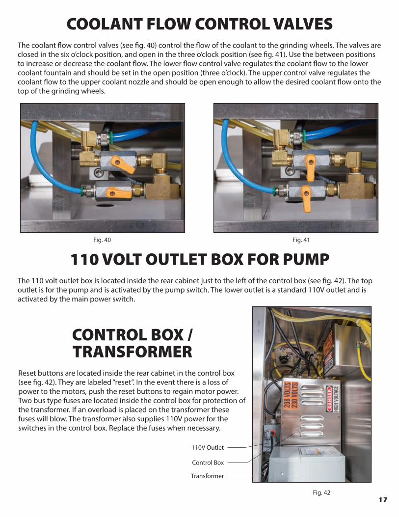
Fig. 42
Fig. 40 Fig. 41
COOLANT FLOW CONTROL VALVESThe coolant �ow control valves (see �g. 40) control the �ow of the coolant to the grinding wheels. The valves are closed in the six o’clock position, and open in the three o’clock position (see �g. 41). Use the between positions to increase or decrease the coolant �ow. The lower �ow control valve regulates the coolant �ow to the lower coolant fountain and should be set in the open position (three o’clock). The upper control valve regulates the coolant �ow to the upper coolant nozzle and should be open enough to allow the desired coolant �ow onto the top of the grinding wheels.
110 VOLT OUTLET BOX FOR PUMPThe 110 volt outlet box is located inside the rear cabinet just to the left of the control box (see �g. 42). The top outlet is for the pump and is activated by the pump switch. The lower outlet is a standard 110V outlet and is activated by the main power switch.
CONTROL BOX / TRANSFORMER
Reset buttons are located inside the rear cabinet in the control box (see �g. 42). They are labeled “reset”. In the event there is a loss of power to the motors, push the reset buttons to regain motor power. Two bus type fuses are located inside the control box for protection of the transformer. If an overload is placed on the transformer these fuses will blow. The transformer also supplies 110V power for the switches in the control box. Replace the fuses when necessary.
Control Box
110V Outlet
Transformer
17

Fig. 43
KNIFE GAUGEThe knife gauge measures the thickness of the taper of a knife blade (see �g. 43). After tapering a knife on the HG3 Hollow Grinder, draw the edge of the blade through the desired slot on the knife gauge (either .023” or .020”). (The .016” slot is a “No Go”. If the knife edge drops freely into this slot the taper of the edge is too thin). A properly tapered blade should �t into the .023” or .020” slot but not touch the bottom of the slot. If the blade edge touches the bottom of the slot, the blade has been tapered too thin. If the blade does not �t into the slot, it needs more tapering on the HG3 Hollow Grinder.
CLEANINGWhen grinding is completed for the day, it is recommended that the HG3 Hollow Grinder be rinsed down.
Push the stop button o� so that only the pump is running. NOTE: Grinding wheels should not be turning. Set the coolant shields aside and using the upper coolant �are nozzle on the jointed line, rinse and wipe the grinding area of the HG3 Hollow Grinder (see �g. 44). After rinsing, reposition the upper coolant �are nozzle so that the coolant �ows onto the front 1/4” of the grinding surface. Clean the coolant shields and set them back in place.
After most of the grinding coolant has drained back into the coolant tank, wipe up the grindings from the cabinet top tray.
Monthly or quarterly a more thorough cleaning is necessary.
Turn o� the HG3 Hollow Grinder and disconnect the air lines or shut o� the air cut-o� valve. Remove the small dresser cover plates that protect the dresser ram assemblies and then the left and right main covers.
Clean as necessary.Fig. 44
18

19
PREVENTATIVE MAINTENANCE SCHEDULE AND RECOMMENDED STOCK ITEMS
PM Schedule and Recommended Stock Items
Daily HG3 HR8 HCA Preventive Maintenance✓ ✓ ✓ Clean machines✓ ✓ Inspect coolant level
✓ Add water to sponge in HWD coverWeekly
✓ ✓ Rotate diamond dresser bits ¼ turn✓ ✓ Clean sock filter & tray filter
✓ Clean or replace wet tray sponge✓ ✓ Change water & additive (3 cups additive/Coolant Tank of water)✓ ✓ Drain air/water separator✓ ✓ ✓ Inspect grinding & honing wheels
Monthly✓ ✓ Replace sock filter✓ ✓ Inspect diamond dresser bits✓ ✓ Inspect hydraulic oil levels
Quarterly✓ ✓ Replace tray filter✓ ✓ Apply anti-seize to dresser ram assemblies & dresser slide rods
Annually✓ ✓ Inspect motor bearings✓ ✓ Remove main covers & clean as necessary
Quantity Recommended Stock Item Description1 set Hollow Grinder Wheels Complete Set (Standard 54 grit)1 set Honing Wheels Complete Set (Standard 220 grit)1 set Honing/Polishing Wheels Complete Set (1000 grit)4 ea. Sponge for HWD Cover1 ea. Cleaner For 1000 Grit Honing Wheels 6 OZ4 ea. Cleaning/Dressing Stick2 ea. Filter, Sock2 ea. Filter, Tray1 ea. Additive, Grinding Coolant - 5 gallons - USDA Approved2 ea. Dresser Bit, Diamond 6” (¼ Carat)3 ea. Bearing, Motor (Small) (Front & Rear HR8) (Rear HG3)1 ea. Bearing, Motor (Large) (Front HG3)1 ea. Motor (HG3 Hollow Grinder)1 ea. Motor (HR8 Honer)
CLD6
HGH4212HG34213HG34201HR84201
CLSTHGH7201HGH7211HGH7112HGH1304
Item #HG37122HR87125HWDTH1716
TRU HONE CORPORATION1721 NE 19th Avenue, Ocala, Florida 34470 USA
USA CANADA 1-800-237-4663 * ALL OTHERS 352-622-1213 * FAX 352-622-9180TruHone.com * [email protected] 9/9/2015
Preventative Maintenance

NOTES
20

Therefore put on the full armor of God, so that when the day of evil
comes, you may be able to stand your ground, and after you have
done everything, to stand. Stand �rm then, with the belt of truth
buckled around your waist, with the breastplate of righteousness in
place, and with your feet �tted with the readiness that comes from the
gospel of peace. In addition to all this, take up the shield of faith, with
which you can extinguish all the �aming arrows of the evil one. Take
the helmet of salvation and the sword of the Spirit which is the word
of God.
Ephesians 6:13-17

7/16
...ends the “Stone Age”
of Knife Sharpening.
TRU HONE CORPORATION1721 N.E. 19th Avenue
Ocala, Florida 34470 USA
USA & Canada Toll-Free800.237.4663 Outside U.S.A
352.622.1213 Fax
352.622.9180
TruHone.com