high-speed chip placer specifications
TRANSCRIPT

High-Speed Chip Placer Specifications
Model
CP-642CP-642E
CNT-CP642-02E
Fuji Machine Manufacturing

Contents
1. Outline................................................................................................1
1.1 Outline ..........................................................................................................1
1.2 Features........................................................................................................1
2. Environmental Specifications..........................................................3
2.1 Electrical Power and Air................................................................................3
2.2 Environmental Conditions.............................................................................3
2.3 Machine Weight ............................................................................................3
2.4 Machine Monitor ...........................................................................................3
2.5 Machine Components...................................................................................4
2.6 Machine Color...............................................................................................4
3. Machine Specifications ....................................................................5
3.1 Basic Specifications......................................................................................5
3.2 Board Transport ............................................................................................6
3.3 PCB Requirements .......................................................................................7
3.4 Warranty .......................................................................................................8
4. Placing Heads ...................................................................................9
4.1 Placing Heads...............................................................................................9
5. Nozzle...............................................................................................10
5.1 Nozzle and Nozzle Assembly .....................................................................10
5.2 Nozzle Arrangement ...................................................................................12
6. Parts Supply System ......................................................................13
6.1 Parts Supply Table (D-axis) and Tape Feeders ..........................................13
7. Vision System .................................................................................16
7.1 Camera Unit (Parts Recognition)................................................................16
7.2 Fiducial Mark Camera.................................................................................17
– i – CP-642(E) Specifications2.0

8. Machine Control System................................................................18
8.1 Machine Control Specifications ..................................................................18
8.2 Signal Tower ...............................................................................................19
9. Options ............................................................................................20
9.1 Installation of Optional Parts and Functions ...............................................20
9.2 Further Information .....................................................................................20
10.Equipment Overview ......................................................................23
10.1 Exterior Schematic......................................................................................23
10.2 Leveling Position.........................................................................................25
10.3 Electrical and Pneumatic Inlets...................................................................26
– ii – CP-642(E) Specifications2.0

1. Outline
1.1 Outline
The CP-642/CP-642(E) is a reliable, high-speed automatic component placement machinewhich places the smallest chips to the larger electronic components on high-densityprinted circuit boards.
The machine performs placing at a maximum speed of 0.09 sec/shot and can be loadedwith up to 140 types of parts. Furthermore, the XY-table speed has been increased on thismodel.
To further reduce noise the machine has been equipped with a rear cover which fullyencloses the device tables.
1.2 Features
• The CP-642/CP-642(E) achieves the world’s fastest placing speed, 0.09 sec/shot, inthe one-by-one chip shooter category. The CP-642/CP-642(E) exhibits animprovement of 25 to 30% in throughput compared with the CP IV-3 and animprovement of 10% compared with the CP-6.
• Computerized design analysis has resulted in a rigid machine structure. This rigidstructure, along with high-accuracy mechanical parts, endows theCP-642/CP-642(E) with the highest possible placement accuracy.
• The simple placing head, consisting of six nozzles per head, expands the number ofpossible nozzle variations and facilitates maintenance.
• A high-speed vision processing system utilizing gray scale technology providesreliable and accurate placement results.
• Press-in type tape feeders reduce the changeover time drastically. Increased rigidityfor 13 and 15-inch reel holders minimizes feeder vibration thereby guaranteeingstable tape feed.
• The newly designed rear cover for the D-axis table reduces the noise generated bythe D-axis feeders from 82 dB to 76 dB, and so improves the working environment.
• The Windows-based F4G (Fuji 4th Generation software) line management systemcontrols the production line with high efficiency. F4G features user-friendlyoperation allowing even beginners to utilize it.
Note: The CP-642/CP-642(E) does not include F4G. The F4G software must be
purchased separately. See the F4G specifications document for details.
– 1 – CP-642(E) Specifications2.0

• An expanded backup pin area has eliminated the restrictions on backup positionsthat existed on the XY-table on previous models. Also, the CP-642/CP-642(E) easilymeets the requirements to load PC boards of 0.5 mm thickness.
• The new loading system employs servo motors to control the PCB lifter rather thanthe air cylinders used on previous models.This system allows the CP-642(E) to shorten the PCB loading and unloading time(reduced from 5 to 4 sec) and control acceleration/deceleration for shock-freeplacement.
– 2 – CP-642(E) Specifications2.1
1. Outline

2. Environmental Specifications
2.1 Electrical Power and Air• Voltage: 3-phase 200 VAC ± 10%
• Frequency: 50/60 Hz
• Power consumption: 10 KVA
Notes:
(1) Input voltage: Selectable from 200, 210, 220, 230, 380, 400, 415, 460 and 480 V
(by selecting the transformer taps)
(2) An exclusive power source should be used for the machine in order to avoid problems from
noise, fluctuations in voltage, and high-frequency distortion.
(3) Compressed air: 0.5 MPa (5 kgf/cm2)
(4) Air consumption: 50 Nl/min
2.2 Environmental Conditions
• Ambient temperature : 15 to 35° C
• Ambient humidity : 30 to 80 %
• Protection Structure : Class IP22 equivalent
2.3 Machine Weight
Approximately 6000 kg (excluding the D-axis rear cover)
2.4 Machine Monitor
Either Japanese or English.
– 3 – CP-642(E) Specifications2.0

2.5 Machine Components
• XY-table
• Board conveyor
• Feeder setting tables
• Nozzles
• Placing heads
• Vision processing system
2.6 Machine Color
Body: Beige
Trim: Reddish brown
– 4 – CP-642(E) Specifications2.0
2. Environmental Specifications

3. Machine Specifications
3.1 Basic Specifications
• Placing Speed 0.09 sec/chip under the following conditions
> XY-table travel distance : within 14.8 mm (within 15.3 mm including compensation)
> D-axis movement : None
> FQ-axis rotation angle : within 20 degrees
> PQ-axis rotation angle : 90° or -90°
> Cam speed : 100%
> 180° rotation placement : 0.13 sec
• Placing Accuracy ±0.1 mm (3 sigma) in XY-direction
> Fiducial mark reference
> Rotational error is translated into an XY-coordinate.
• Placing Reliability 99.99 % (After auto recovery)
• Part Dimensions 1005 to 19 x 20 mm (20 x 20 mm for J-lead parts)
Part height: maximum 6 mm
• Package Type 8, 12, 16, 24 and 32 mm tape
Reel diameter: 180 mm, 330 mm and 380 mm
• Maximum Feeder Number 140 feeders (using 8 mm tape feeders)
• Board Loading Time 4.0 sec (XY-table travel time is not included)
• Fiducial Mark Read Time Approximately 0.5 sec/mark
> 1.2 mm mark diameter. Time needed to move between the marks and to compensate for mark appearance and displacement is not included.
• Nozzle Indexing Time 1 pitch rotation: 0.09 sec
2 pitch rotation: 0.15 sec
3 pitch rotation: 0.18 sec
– 5 – CP-642(E) Specifications2.1

3.2 Board Transport
(1) Direction of Board Flow
• Left to right – Standard
• Right to left – Optional
(2) Board Transport Height
• 900(+15, –5) mm Standard
• 950(+15, –5) mm Optional
Vibration isolation pads may increase the board transport height by 12 mm.
(3) Board Transport
• Conveyor belt system
• In-conveyor -> main conveyor (XY-table) -> out-conveyor
(4) Maximum Transport Weight
• 1 kg maximum (2 kg with optional roller guided conveyor)
(5) Conveyor Width Adjustment
• The width of the conveyors can be changed individually or jointly using theadjustment handle and the front rail as a reference.
– 6 – CP-642(E) Specifications1.0
3. Machine Specifications

3.3 PCB Requirements
(1) Board Size
• 356 mm (W) x 457 mm (L) maximum
• 50 mm (W) x 80 mm(L) minimum
• Thickness 0.5 mm – 4.0 mm
Note: Consult Fuji if board backup is required.
(2) Board Material
• Glass epoxy, composites, paper phenol, alumina, polyimide, etc.
(3) Board Restrictions
• Warpage: ±1.0 mm maximum
• Height of premounted parts: 6.0 mm maximum
• Height of premounted bottom side parts: 25.4 mm
– 7 – CP-642(E) Specifications2.0
3. Machine Specifications

3.4 Warranty
• Warranty period 2000 hours or 1 year. Fuji will bear no responsibility for damage due to acts of nature (fire, flood, earthquakes, etc) or incorrect operation.
– 8 – CP-642(E) Specifications2.0
3. Machine Specifications

4. Placing Heads
4.1 Placing HeadsStation Function1 Pick-up part from the D-table2 Part detection (large part only)3 Pθ: Placement angle pre-rotation in 90 degree angles4 Idle5 θ−axis nozzle rotation6 Vision processing7 Idle8 Idle9 Idle10 Fθ: Fine placement angle rotation (incl. adjustment)11 Placement12 FRθ:Fθ: Fine rotation origin return13 PRθ:Pθ: Pre-rotation origin return (cam driven)14 A-head detection15 Nozzle clutch origin detection16 NG parts discarded17 Detection of nozzle type No. 1 - No. 618 Nozzle change19 Nozzle change check (detect type No. 1 - 6)20 Idle
– 9 – CP-642(E) Specifications2.0

5. Nozzle
5.1 Nozzle and Nozzle Assembly
(1) Each placing head carries up to 6 nozzles of different types, selected from a range of15.
(2) Refer to the following table for nozzle types and applicable parts.
1005, 1608, SSMIN
1608, 2125, SMIN, MIN
2125, 3216, MIN, Tantalum A, Melf
3216, 3225, 4532, Tantalum A/B,
PTRR, Trimmer potentiometer
Tantalum B/C/D, PTRR, Melf,
SOIC 8, SSOP 16 ~ 20, Filter
SOIC 20~28W, SSOP 24~30, PLCC 18~32,
SQFP 48, SOJ 26, QFP 48
ø0.7
ø1.0
ø1.3
ø1.8
ø2.5
ø5.0
ø3.7
ø12
ø20
Bkgd Nozzle diameter Applicable parts
Trimmer potentiometer,
Aluminum electrolytic capacitor,
Tantalum D, SOIC 20~28W, SSOP 16~30,
PLCC 18~28, SQFP 48, SOJ 26
20 mm
Nozzle name
ø16
square
22 mmsquare
22 mmsquare( black )
ø7.0 SOIC 20~28W, SOJ 26, PLCC 20~52
R12-007
R12-010
R12, M12-013
R12-018
R16-025R20, M20-025
R16-037
R20-037
S20-050
S22-050
B22-050
S22-070
B22-070
– 10 – CP-642(E) Specifications1.0

5. Nozzle
Notes:
(1) The letter in "Nozzle name" denotes the shape of the diffuser (except M&B).R : Round (back light)M : Special nozzle for Melf (back light)S : Square (back light)B : Square (front light) (B indicates black)
(2) Depending on the shape and weight of the part, a different nozzle may be required.
– 11 – CP-642(E) Specifications1.0

5.2 Nozzle Arrangement
The standard arrangement of nozzles is either type A or B, as shown below. Otherarrangements made up of nozzles A ~ O are possible.
The nozzle types listed here are identified in the following table.
Notes: (1) Only a nozzle with a ø20 reflective disk or smaller can be attached on either
side of a nozzle with a 20 mm square reflective plate.
(2) Only a nozzle with ø16 reflective disk or smaller can be attached on either
side of a nozzle with a 22 mm square or 22 square (black) reflective plate.
1
2
3
4
5
6
R12-007
R12-010
R12-013
R20-025
R20-037
S20-050
1
2
3
4
5
6
R12-010
R12-013
R12-018
R20-025
R20-037
S20-050
Type A
Nozzle Types
Type B
ABCDE
R12-007R12-010R12-013M12-013R12-018
FG
HIJK
R16-025R16-037
R20-025M20-025R20-037S20-050
S22-050B22-050S22-070B22-070
LMNO
Position on Head Type AType B
Type A and Type B Nozzle Arrangements
1AB
2BC
3CE
4HH
5JJ
6KK
– 12 – CP-642(E) Specifications1.0
5. Nozzle

6. Parts Supply System
6.1 Parts Supply Table (D-axis) and Tape Feeders
(1) Types of Components 140 types (using 70 x 2 tables with 8 mm feeders)
(2) Placeable Components Components that comply with the packaging, feed pitch and parts height requirements as previouslyoutlined.
(3) Table Drive Method 2 motor/2 independent drive mechanisms.
(4) D-table Drive Modes May be selected from the following
• Device Change Mode
• Changeover Mode
• Joint Mode
(5) Feeder Pitch
Note: The expressions "left side" and "right side" refer to the feeder mounting positions when
viewed from the rear of the machine.
(6) Feeder Types (which can be placed at the ends of the device tables)
W8 W12N/AN/AN/AN/A
D1D70D71D140
√√√√
W16N/AN/AN/AN/A
W24N/AN/AN/AN/A
W32N/AN/AN/AN/A
W8W12W16W24W32
W81P2P2P2P2P
W122P2P2P2P3P
W162P2P2P2P3P
W242P2P2P3P3P
W322P3P3P3P3P
Lef
t sid
e
Right side
– 13 – CP-642(E) Specifications1.0

– 14 – CP-642(E) Specifications1.0
6. Parts Supply System
(7) Feeder Stands
• A feeder stand is a 3-tier shelf designed to accommodate unused or spare feeders.Shelves can be selected from the following list and attached to the stand.
(8) List of CP642/CP642(E) Compatible Feeders
For 330 mm reel
WD-0804-1.0-330
WD-0804-1.3-330
WD-0804-1.8-330
WE-0804-1.0-330
WE-0804-1.3-330
WE-0804-1.8-330
WE-1204-2.5-330
WE-1208-2.5-330
WE-1212-2.5-330
WE-1604-3.7-330
WE-1608-3.7-330
WE-1612-3.7-330
WE-2404-5.0-330
WE-2408-5.0-330
WE-2412-5.0-330
WE-2416-5.0-330
WE-2424-5.0-330
WE-3212-7.0-330
WE-3216-7.0-330
WE-3224-7.0-330
For 380 mm reel
WE-1204-2.5-380
WE-1208-2.5-380
WE-1212-2.5-380
WE-1604-3.7-380
WE-1608-3.7-380
WE-1612-3.7-380
(12 mm Double feeding)
(12 mm Double feeding)
For 180 mm reel
WD-0802-0.7-180
WD-0804-1.0-180
WD-0804-1.3-180
WD-0804-1.8-180
WE-0802-0.7-180
WE-0804-1.0-180
WE-0804-1.3-180
WE-0804-1.8-180
WE-1204-2.5-180
WE-1208-2.5-180
WE-1212-2.5-180
Feeder Stand
Holds 8, 12 mm
Holds 16 mm
Holds 24 mm
Holds 32 mm
(3 Shelves/ Stand)
(accommodates 34 feeders)
(accommodates 27 feeders)
(accommodates 22 feeders)
(accommodates 19 feeders)

Notes: (1) Both 330 and 380 diameter reels can be mounted on reel holders. The
feeding capacity is a maximum 10,000 parts at 4 mm/pitch and a maximum
5,000 parts at 8 mm/pitch.
(2) A part is fed by a single stroke for a pitch of 2, 4, 8, 12 and 16 mm, and by
multiple strokes for a pitch up to 24 mm.
(24 mm is the maximum length of tape which can be cut off.)
(3) 380 diameter reel holders are manufactured on demand.
(4) The reel's alphanumeric number includes the applicable nozzle size. The
size is the maximum nozzle diameter. Nozzles of smaller diameter can be
used on the feeder as well.
(5) All FCP-6 dedicated feeders are made of aluminum.
(6) The dimensions of the W8, 13-inch parts reel are shown below.
Feeders for the CP6 use a box-type reel holder, providing structural stability
which ensures repeated component pick-up accuracy.
– 15 – CP-642(E) Specifications1.0
6. Parts Supply System
7. Vision System
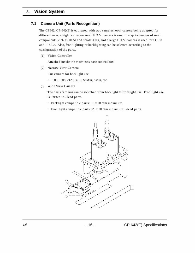
7.1 Camera Unit (Parts Recognition)
The CP642/CP-642(E) is equipped with two cameras, each camera being adapted fordifferent uses; a high resolution small F.O.V. camera is used to acquire images of smallcomponents such as 1005s and small SOTs, and a large F.O.V. camera is used for SOICsand PLCCs. Also, frontlighting or backlighting can be selected according to theconfiguration of the parts.
(1) Vision Controller
Attached inside the machine's base control box.
(2) Narrow View Camera
Part camera for backlight use
• 1005, 1608, 2125, 3216, SSMin, SMin, etc.
(3) Wide View Camera
The parts cameras can be switched from backlight to frontlight use. Frontlight useis limited to J-lead parts.
• Backlight compatible parts: 19 x 20 mm maximum
• Frontlight compatible parts: 20 x 20 mm maximum J-lead parts
– 16 – CP-642(E) Specifications1.0

Notes: (1) Specify the camera type, narrow or wide view, in part data.
(2) If a part larger than 3216 in size is inspected using the narrow view camera, the
placing speed may be reduced. The narrow view camera is intended for inspecting small
components at high resolution.
(3) If a part smaller than 4532 in size is inspected using the wide view camera, the placing
accuracy may be adversely affected. The wide view camera is designed for large components
from 4532 size parts to SQFP 48 pin devices.
7.2 Fiducial Mark Camera
(1) The camera is installed within the head assembly.
(2) The camera is used to accurately locate the board position by inspecting two ormore fiducial marks on the PCB. During operation, corrections are made to the partplacement position using this fiducial mark data.
– 17 – CP-642(E) Specifications1.0
7. Vision System

8. Machine Control System
8.1 Machine Control Specifications
(1) Placement Position Data Entry • Absolute data
(2) Acceleration Control (XY-table) • UHi, Hi, Mid, Low, ULow: 5-level adjustable acceleration anddeceleration settings.
(3) Controllable Axes • Cam, X, Y, Z, D1, D2, Fθ, FRθ, Nozzle changer: 9 axes
(4) CPU • 32 bit
(5) Maximum Number of Input Sequences • 5,000 sequences/board
(6) Maximum Number of Programs • 10 (1,500 sequences/program)in Storage
(7) Memory • Battery backup (lithium battery)
(8) Data Input • F4G systemNote: Refer to 9.2.12, “F4G System”.
(9) Data Unit • 0.01 mm on X-, Y- and Z-axes.• θ axis units : deg. and min.
(10) Communication • RS-232C
(11) Control Panel • Numerical keypad and function keys
(12) Vision Recognition Error Correction • Board displacement correction• Part displacement correction
– 18 – CP-642(E) Specifications1.0

8.2 Signal Tower
Notes:
(1) The signal tower lighting condition settings are made in Proper data.
(2) The blue light is replaced by a green light on IEC-compatible machines.
Machine Status
Automatic Operation
Board Loading
Board Waiting
Command Waiting
Parts Out
M/C Stop Due To Parts Out
M/C Stop Due To Error
Statistical Warning
Operator Call During Changeover
Vision Processing Error
Ready Mode
Changeover In Process
M/C Stop Due To Production Count Up
Blue(steady)
√
√
√
√
Blue(flashing)
√
√
√
√
Yellow(steady)
√
√
Yellow(flashing)
√
√
√
Red(steady)
√
Red(flashing)
√
– 19 – CP-642(E) Specifications1.0
8. Machine Control System

9. Options
9.1 Installation of Optional Parts and Functions
The options listed below are categorized into three groups.
Category A Factory installed (installed by Fuji prior to shipping)
Category B Site installed (installed on-site by Fuji)
Category C User installed (installed by the customer)
• Reference pin unit A or B
• Reference pins C
• Backup pins C
• Vacuum-type backup pins A or B
• Additional nozzles C
• Tape feeders C
• Handy terminal C
• Board-flow direction A
• Roller-guided conveyor A
• Tri-color signal tower A
• HELPS A
• F4G C
• Others
9.2 Further Information
9.2.1 Reference Pin Unit
(1) The CP642/CP-642(E) comes equipped with a fiducial mark camera thatreads fiducial marks to ascertain a board's position. Board-holding units foruse with reference pins are available as an option.
(2) Reference pin units can be used together with fiducial marks.
(3) The reference pin unit does not include reference pins. The reference pinsmust be ordered using the customer specification form.
– 20 – CP-642(E) Specifications1.0

9.2.2 Reference Pins
The following reference pins are available. Please specify the quantity and sizein your order.
• ø3.0 round or diamond shaped
• ø4.0 round or diamond shaped
9.2.3 Backup Pins
Order backup pins as needed
9.2.4 Vacuum Style Backup Pins
6 pins are used. Use of the vacuum backup pins increases board loading time byone second compared to standard backup pins. However, this may varydepending on the specified table mode.
Loading Speed Mode Time(sec)
Hi 5.0
Mid 5.5
Low 6.0
9.2.5 Additional Nozzles
Order additional nozzles as needed.
9.2.6 Part Supply Feeders
8, 12, 16, 24 and 32 mm feeders are available. Note requirements in your order.
9.2.7 Handy Terminal
(1) Permits the operator to conveniently enter and view data normallydisplayed on the control CRT during device checks.
(2) Eliminate errors when replacing reels by allowing device checks via theattached pen-type barcode reader.
9.2.8 Board-flow Direction
(1) Provides support for right to left board flow.
9.2.9 Roller-Guided Conveyor
(1) This unit enhances board transport performance by incorporating rollersunder the PCB transport conveyor belt.
(2) The maximum weight allowable is 1 to 2 kg including the transport pallet.
– 21 – CP-642(E) Specifications2.0
9. Options

9.2.10 Tri-color Signal Tower
(1) Customer selectable green or blue lights with standard red and yellowlights.
9.2.11 HELPS Specifications
(1) The HELPS system provides an in-line production system that supportsautomatic changeover. The main features are as follows:
• Automatic changeover of production programs
• Automatic conveyor width adjustment
• Displays confirmation items and manual procedure instructions forautomatic changeover operation.
(2) The level of automation varies according to the customer's specification .
• Board type (barcode or pattern-code) trigger.
• Manual (operation SW) trigger
Note: When a barcode or pattern-code is used as a trigger, a separate unit to
read data at the previous stage is required. Details are available
separately.
9.2.12 F4G System
(1) The F4G system performs data communication with the machine using thefollowing:
• Computer (IBM PC compatible )
• C/C (communication center)
• Program modules (F4GO, F4GP, F4GM, etc. as required)
(2) Refer to the the separate “F4G Specifications” for details.
Note: The PC for the F4G system should be prepared by the customer prior to
the installation of the machine.
9.2.13 Other Requirements
(1) Any requirements not covered in these specifications may be discussedseparately.
(2) If you have any questions, please contact Fuji or one of our salesrepresentatives.
– 22 – CP-642(E) Specifications1.0
9. Options

10. Equipment Overview
10.1 Exterior Schematic
10.1.1 Models with Rear Cover
– 23 – CP-642(E) Specifications2.0

10.1.2 Models with Fence
– 24 – CP-642(E) Specifications2.0
10. Equipment Overview

10.2 Leveling Position
1005
770
750
755
350
875
770
750
755
4545
4551540 475
5050
4551540 475
Uni
t: m
m
– 25 – CP-642(E) Specifications1.0
10. Equipment Overview

10.3 Electrical and Pneumatic Inlets
Note: Fuji does not supply the hose.
3 phase cable
Main breaker
Ground line
Electrical Outlet
20PM plug
Socket
Hose
20SH (for 1/4” hose)
0.5Mpa (5 kg/cm ) or more2
30SH (for 3/8” hose)
40SH (for 1/2” hose)
Air inlet
Electrical inlet
– 26 – CP-642(E) Specifications1.0
10. Equipment Overview

For inquiries concerning this specifications manual pleasecontact Fuji at one of the offices listed below.
Headquarters –––––––––––––––––––––––––––––––––––––––––––––
Fuji Machine Manufacturing Co., Ltd.19 Chausuyama Yamamachi, Chiryu, Aichi, 472-8686 Japan
Tel.: (0566) 81 - 2110 FAX: (0566) 83 - 1140
Overseas Offices ––––––––––––––––––––––––––––––––––––––––––
Fuji America Corporation
171 Corporate Woods Parkway Vernon Hills, IL. 60061 USA
Tel.: (847) 913-0162 FAX: (847) 913-0186
Fuji Machine Mfg (Europe) GmbH
Peter-Sander-Str. 43 D-55252 Mainz-Kastel Germany
Tel.: 06134-202120 FAX: 06134-202200
Fuji Singapore Office
C/O Mecomb Singapore Limited Sime Darby Centre 896 Dunearn Road #04-03A, Singapore 589472
Tel.: 4675952. FAX: 4693758
Fuji Malaysia Office
C/O Mecomb Malaysia Sdn Bhd 2487, Jalan Sultan Azlan Shah 11700 Penang, Malaysia
Tel.: 604-656-4002 FAX: 604-656-2941
Fuji Do Brazil Maquinas Industrials Ltda.
Edificio Eluma Avenida Paulista 1294-5 Andar Sao Paulo, S. P. CEPO 1310-100 Brazil
Tel.: 11-284-6511 FAX: 11-289-1097––––––––––––––––––––––––––––––––––––––––––––––––––––––––––
CP-642(E) Specifications1st Version October 1, ’962nd Version January 16, ’972.1 Version January 14, ’98
Fuji Machine Manufacturing Co., Ltd.SMT Engineering Division19 Chausuyama, Yamamachi, Chiryu,Aichi Prefecture, 472-0006 Japan
––––––––––––––––––––––––––––––––––––––––––––––––––––––––––
The specifications are subject to change without notice.
Copyright 1998 by Fuji Machine Manufacturing Co., Ltd.Printed in Japan