high-speed serial interface circuits and systems
TRANSCRIPT
High-Speed Serial Interface Circuits and Systems
Lect. 4 – Phase-Locked Loop (PLL) Type 1
(Chap. 8 in Razavi)

PLL• Phase locked loop
A (negative-feedback) control system that generates an output signal whose phase (and frequency) is related to the phase (and frequency) of an input reference signal – wikipedia –
• Output signal is phase-locked to reference signal: Constant phase relationship fout = M x fReference
PhaseDetector
LoopFilter
VoltageControlledOscillator
Divisionby M
ReferenceOutput

PLL• Applications
• Frequency Synthesis - Clocks for digital systems- LO in RF systems
• Clock recovery• Modulation/Demodulaton

PLL Block Diagram
• Reference?
PhaseDetector
LoopFilter
VoltageControlledOscillator
Divisionby M
ReferenceOutput
Equivalently, an LC oscillator
Oscillation frequency: kHz ~ a few hundred MHz

Phase-tracking by PLLD
ista
nce
time
• Cameraman can only control the accelerator (velocity)• Distance: Integral of velocityControl of velocity in order to lock the distanceAfter locking, distance and velocity should be the same

Phase-tracking by PLL
Abs
olut
e ph
ase
time
PLL achieves phase-locking by changing VCO frequency
PhaseDetector
LoopFilter
VoltageControlledOscillator
Divisionby M
ReferenceOutput

PD (Phase Detector): Compares phases of input and output signal and converts the phase difference to voltage signal
LPF (Low Pass Filter): Takes an average level of PD’s output voltage signal
PD can be realized with a multiplier
sin( )sin( )in outt t 1 cos[( ) ] cos[( ) ]2 in out in outt t
Basic PLL Operation

Approximately linear for = - /2
Assuming in=out
sin( )sin( )in outt t 1 cos[( ) ] cos[( ) ]2 in out in outt t
Filtered out by LPF
Basic PLL Operation

VCO (Voltage Controlled Oscillator): Frequency-tunable oscillator Output frequency is a function of control voltage (VC)
Basic PLL Operation

Phase tracking of PLL
Vin
Vout
VPD
Initially, Vout is locked to VinWith Phase jump in Vin here
ωin=ωout
Basic PLL Operation

Frequency tracking of PLL
Vin
Vout
VPD
ωin≠ωout
Frequency jump in Vin hereVout is locked to VinWith
Basic PLL Operation

A B VPD
0 0 00 1 11 0 11 1 0
XOR gate can be used as PD for digital signals
A
BVPD Locked
(π/2 phase offset)
A
B
VPD
B later than A
A
B
VPD
B earlier than A
A
B
VPD
Basic PLL Operation

Phase tracking of PLL
Vin
Vout
VPD
Vout is locked to Vin(π/2 phase offset)
ωin=ωout
DC level → VC
Phase jump in Vin here
Basic PLL Operation

Frequency tracking of PLL
Vin
Vout
VPD
Vout is locked to Vin
ωin≠ωout
Frequency jump in Vin here
Basic PLL Operation
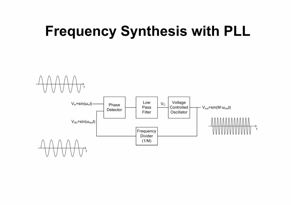
Frequency Synthesis with PLL

(FM signal)
(Recovered message)
(PLL output)
Frequency Demodulation with PLL

Linear approximation for PD characteristics LPF: First order with pole at s = - p
( )( )
( )C
PD
V sT s
V s
in – out)
VPD
VPD (s) = KPD x (s)
PLL Dynamics: Linear Model
p
ps

out (s) =
For simplicity let 0=0
Since d/dt =
PLL Dynamics: Linear Model
(1/s) KVCO x VC (s)
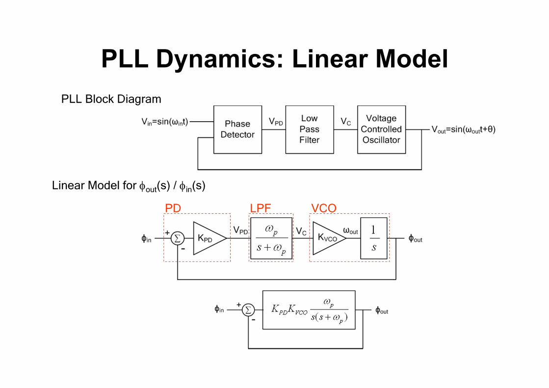
PLL Block Diagram
PD LPF VCO
Linear Model for out(s) / in(s)
PLL Dynamics: Linear Model

Open loop gain:
( )( )
pPD VCO
p
G s K Ks s
Closed loop gain
( )( )( )
out
in
sH ss
2PD VCO p
p PD VCO p
K Ks s K K
( )
1( )
pPD VCO
p
pPD VCO
p
K Ks s
K Ks s
2nd order LPF!
( )1 ( )
G sG s
PLL Dynamics: Linear Model
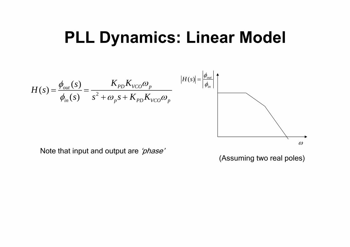
2
( )( )( )
PD VCO pout
in p PD VCO p
K KsH ss s s K K
( ) out
in
H s
Note that input and output are ‘phase’
(Assuming two real poles)
PLL Dynamics: Linear Model
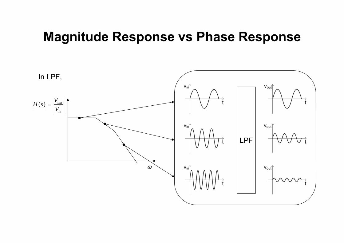
In LPF,
LPF
( ) out
in
VH sV
Magnitude Response vs Phase Response
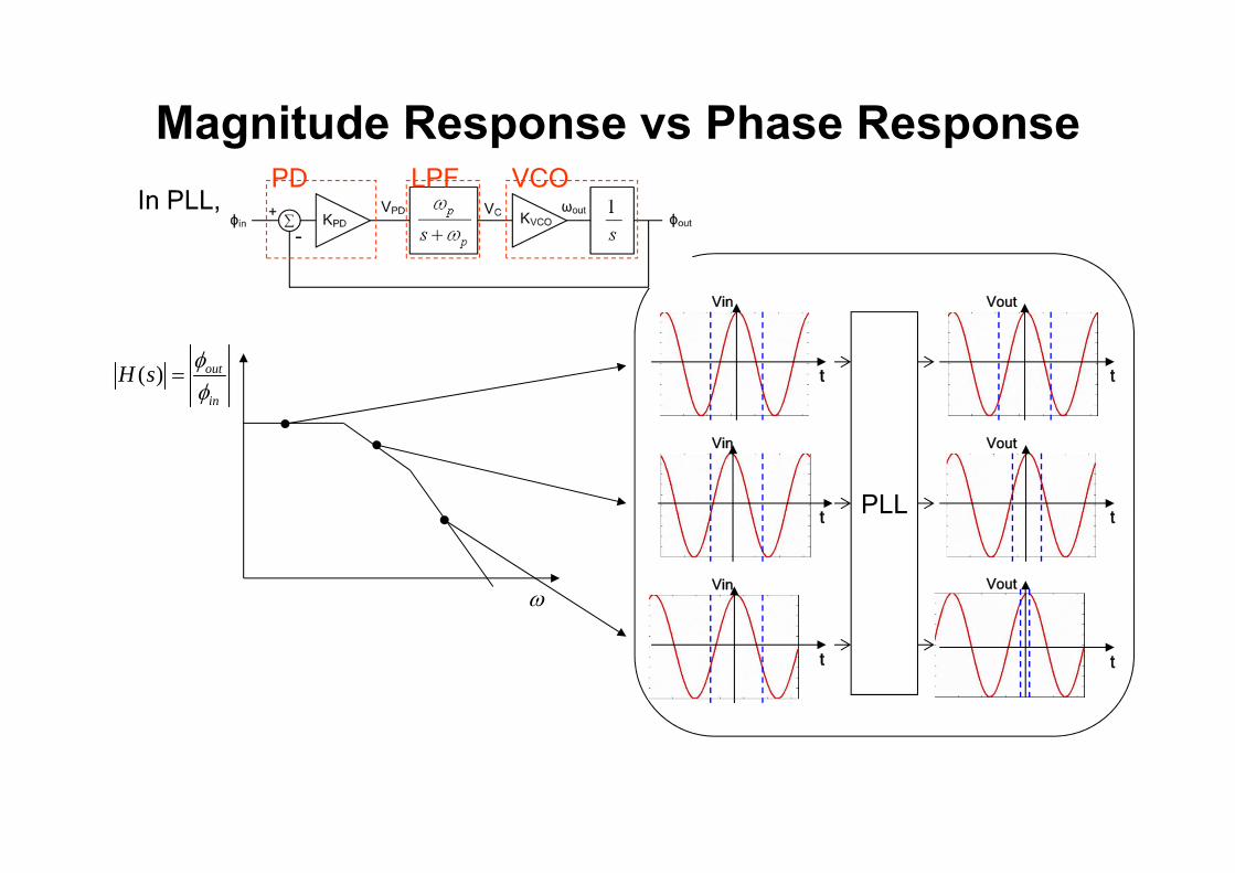
In PLL,
( ) out
in
H s
PLL
Vin Vout
t t
Vin Vout
t t
Vin Vout
t t
PD LPF VCO
Magnitude Response vs Phase Response

2
( )( )( )
PD VCO pout
in p PD VCO p
K KsH ss s s K K
n PD VCO PK K PD VCO
P
K KQ
2nd order system2
2 2( )( / )
n
n n
H ss Q s
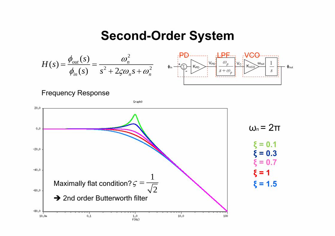
PD LPF VCO
Second-Order System
1 12 2
P
PD VCOQ K K
2
2 2( )2
n
n n
H ss s
Where are the poles? > 1: Over damped
1: Under damped
1: Critically damped
2
2 2
( )( )( ) 2
out n
in n n
sH ss s s
PD LPF VCO
Second-Order System
Frequency Response
ξ = 0.1ξ = 0.3ξ = 0.7ξ = 1ξ = 1.5
ωn = 2π
Maximally flat condition? 12
2nd order Butterworth filter

PD LPF VCO
( )( )
out
in
s ss s
2
2 22n
n ns s
( )( )
out
in
ss
Second-Order System
Step response: ( ) ( )in t u t
PLL
exp nt
2
2 2
( )( )( ) 2
out n
in n n
sH ss s s

PD LPF VCO
Second-Order System2
2 2
( )( ) 2
out n
in n n
ss s s
ξ = 0.1ξ = 0.3ξ = 0.7ξ = 1ξ = 1.5
ωn = 2π
Step response: ( ) ( )in t u t
PD LPF VCO
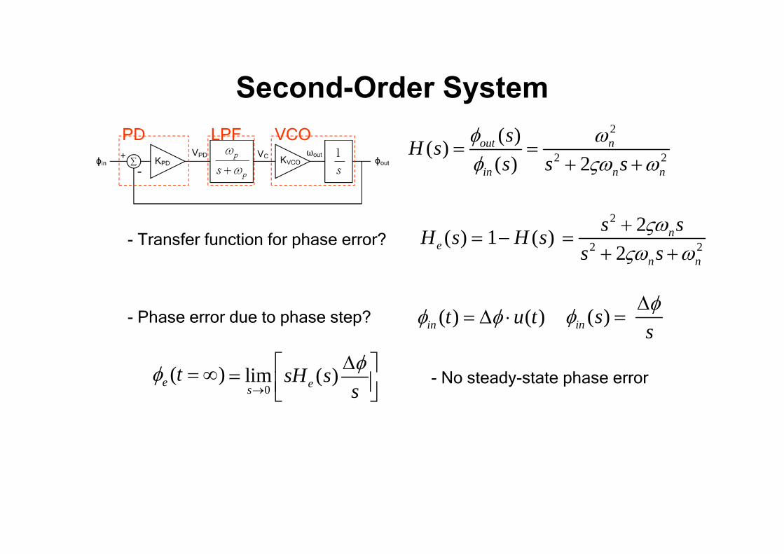
- Transfer function for phase error?
Second-Order System
( )e t
- Phase error due to phase step? ( ) ( )in t u t ( )in s
0lim ( )es
sH ss
- No steady-state phase error
( )eH s
2
2 2
( )( )( ) 2
out n
in n n
sH ss s s
1 ( )H s2
2 2
22
n
n n
s ss s
s

PD LPF VCO
Second-Order System2
2 2
( )( )( ) 2
out n
in n n
sH ss s s
2
2 2
2( )2
ne
n n
s sH ss s
20lim ( )es
sH ss
( )e t ( ) ( )in t u t
( )in s
( )in s
s
2s
2
n
PD VCOK K
- Phase error due to frequency step?