•high temperature thermoelectric · pdf filec,, •high temperature thermoelectric...
TRANSCRIPT
FIFTH QUARTERLY PROGRESS REPORT
C,, •HIGH TEMPERATURETHERMOELECTRIC RESEARCH
q im I JANUARY 1963- 29 MARCH 1963
C.) CONTRACT AF 33(657)-7387PROJECT NO. 8173 TASK NO. 817302-9
AUTHOR CONTRIBUTORSG. H. RINGROSE
C.M. HENDERSON R. G. AULTEMIL BEAVERR.J. JANOWIECKIH. B. JANKOWSKYL. REITSMA
ý .. MONSANTO RESEARCH CORPORATIONA SUBSIDIARY OF MONS&ANTO CHEMICAl, COMPANY
S~M DAYTON_ LABORATORY
,,To,,, 7. O01O ASTIA
-APR •22 I,.v..' . D

FOREWORD
This report describes work performed under Contract AF 33(657)-7387, Project No. 8173, Task No. 817302-9 during the period1 January 1963 - 29 March 1963. The contract concernsdevelopment of a high temperature thermoelectric generator, andis under sponsorship of the Flight Accessories Laboratory,Directorate of Aeromechanics, Aeronautical Systems Division,Wright-Patterson Air Force Base, Ohio. For the Air Force,Mr. Charles Glassburn is project engineer.
The contract is being performed by Monsanto Research Corporationat its Dayton Laboratory with C. M. Henderson as project leader.Working with him are R. G. Ault, Emil Beaver, H. Jankowsky,R. Janowiecki, L. Reitsma, and G. H. Ringrose. Technicalassistance was provided by R. R. Hawley, C. D. Reinhardt, D. Sevyand D. Swihart.
4
0 MONSANTO RKSEARNC CORPORATION S
ABSTRACT
An experimental model 5-watt (nominal) generator completed 2556 hrsof a sustained performance test at a hot-end temperature of .2000C(+25 0 C-4 0C),cold end at 714 0C (+12 0 C-00 C),in a vacuum of I0-P -10- mm Hg without degradation in power producing characteristics.The power/weight ratio of this generator, exclusive of heat source,ranged from 2.70 to 2.86 watt/lb. Tests at 1300*C and highertemperatures will be attempted with this generator.
Graphite-ended segmented modules of n- and p-type thermoelectricmaterials to supplement p-type MCC 50, the thermoelectric materialused in the 5-watt generator, were fabricated and partiallyevaluated. The first such p-n couple produced 250% more power thanthe p-type MCC-molybdenum couple used in the 5-watt generator.Improved emissive coatings and lightweight Junctions between moduleswere produced. Theee developments suggest that an advancedexperimental 50-watt generator having a power/weight ratio of10-20 watt/lb is feasible.
iii
* MONSANTO RESEARCH CORPORATION 0

TABLE OF CONTENTS
Page
II. INTRODUCTION AND SUMMARY 1
II. RESEARCH AND DEVELOPMENT RESULTS 3
A. Experimental Model Evaluation 3B. Component Improvement and Evaluation 20
III. CONCLUSIONS 41
IV. FUTURE PLANS 41
iv
0 MONSANTO RESEARCH CORPORATION 0
LIST OF FIGURES
Figure Title Page
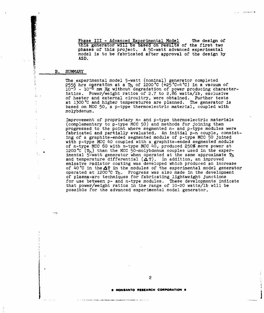
1 Arrangements of heater element, thermocouples andconstruction details of 5-watt experimental modelgenerator for 2500-hr duration test. (Thermalinsulation between modules not shown). 4
2 System for monitoring and controlling operationconditions of the model generator during the 2500-hbtest 5
3 Experimental model generator mounted and ready forduration testing. 7
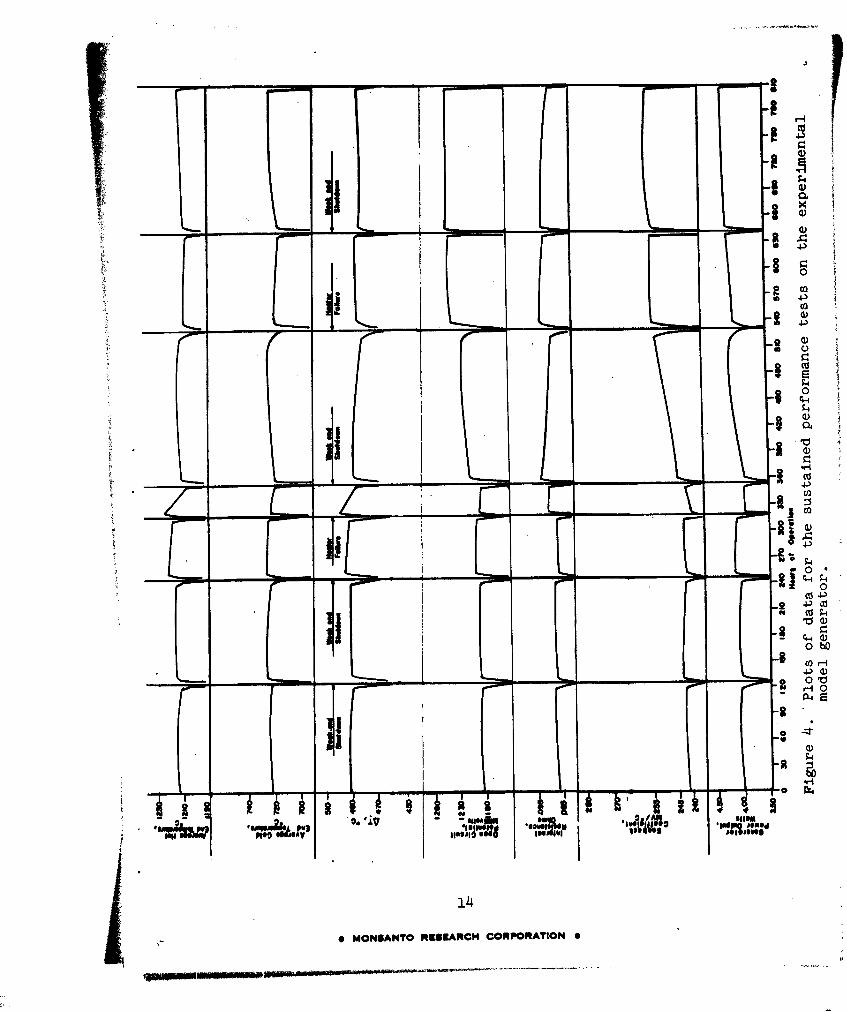
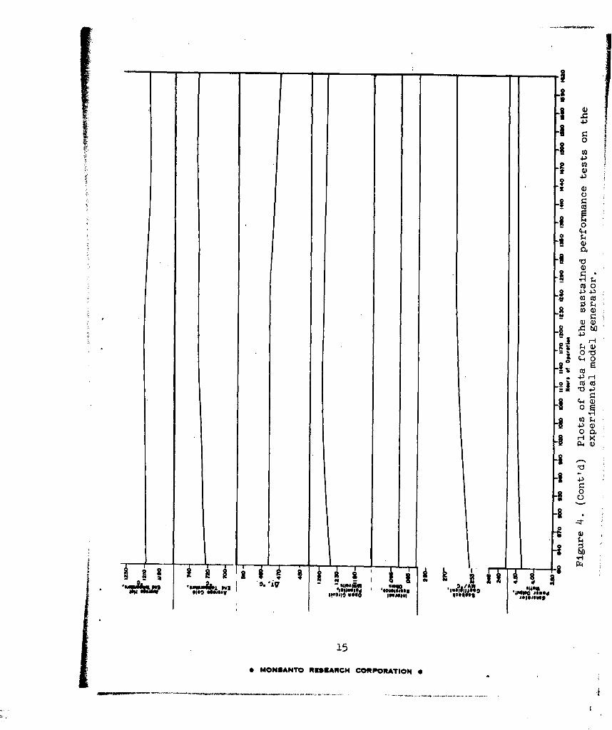
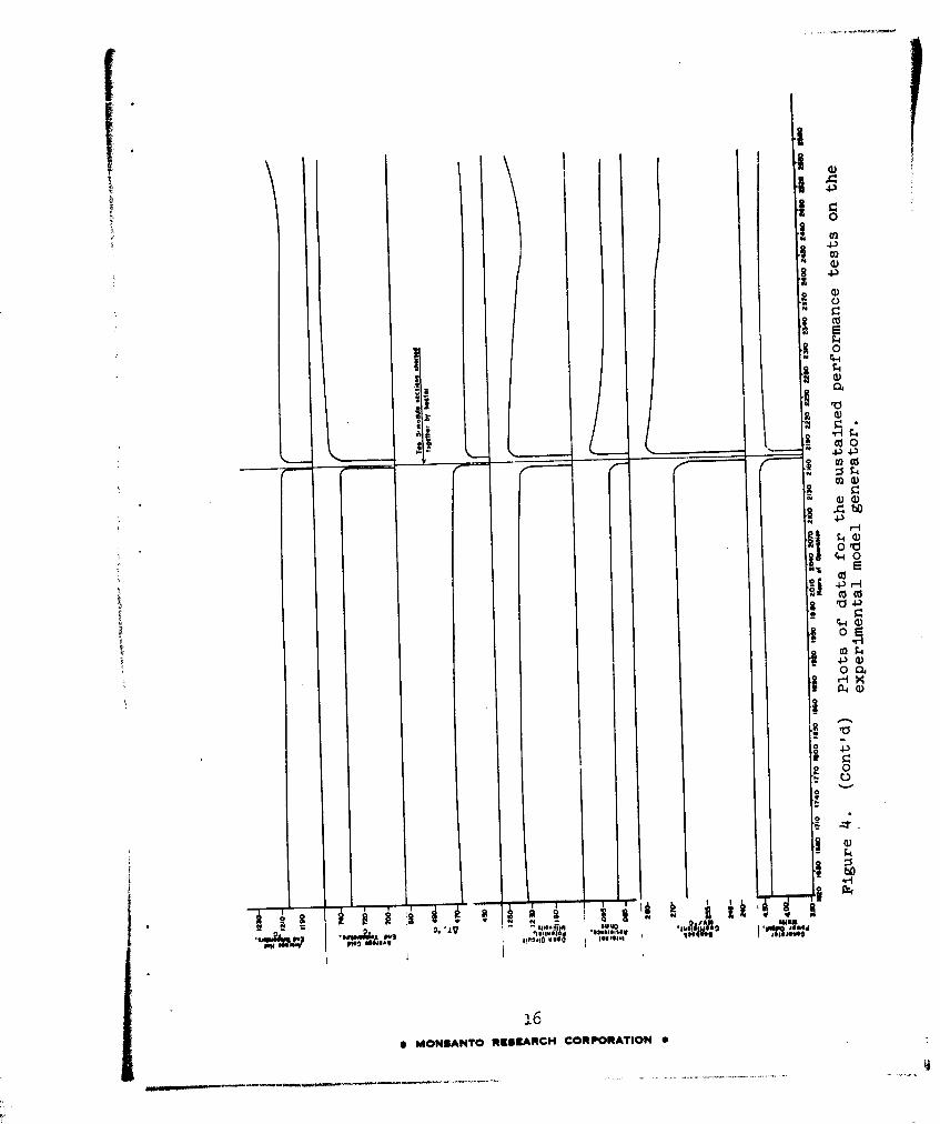
4 Plots of data for the sustained performance testson the experimental model generator. 14
5 Appearance of experimental model generator after2556-hrs egposure at a Th of 1200 0 C in a vacuum of10-5 - 10- mm Hg. 18
6 Proposed arrangement of segmented p- and n-typematerials for use in an advanced experimental modelgenerator. 19
7 Graphite-ended p-type segmented module of MCC 50-MCC 40. 29
8 Graphite-ended n-type segmented module of MCC 60-MCC 40. 30
9 Sandwich-type module 86D made by arc-plasma spraycoating a thin coat of molybdenum on the graphitebase, followed by a 1/8" layer of MCC 50 and a finalcold junction layer of molybdenum. 32
10 Experimental 2-leg module with arc-plasma spraycoated molybdenum hot and cold junctions. 33
11 Experimental 2-leg module with arc-plasma spraycoated molybdenum cold (radiator) junction. 34
12 Typical graphite hot-end junction configuration forevaluating graphite-ended p-n couples. 36
13. Partial test configuration used to evaluate graphite-ended segmented p-n couple showing modules joined with0.005" x i" x 1 1/4" moJybdenum and graphite hotjunction and surrounded by radiant heat shields. 37
14 Completed test configuration used to conduct sustainedevaluation tests on p-n couples. 38
v
0 MONSANTO R[SEARCH CORPORATION 0

LIST OF TABLES
Table Title Page
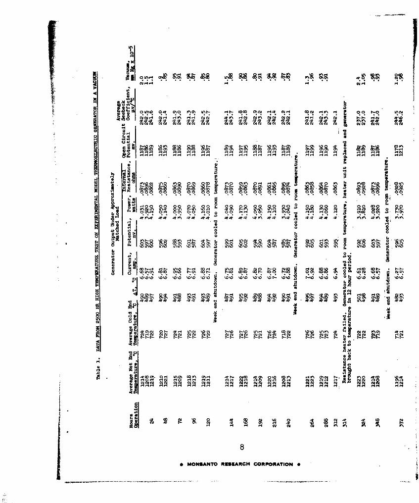
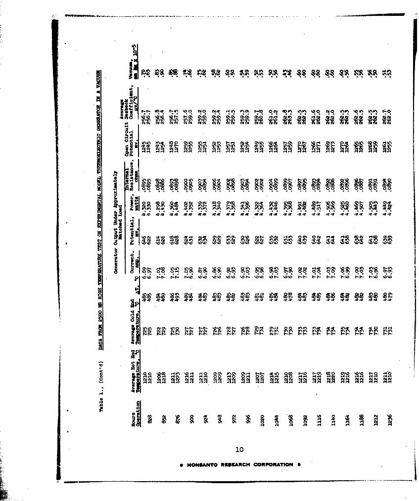
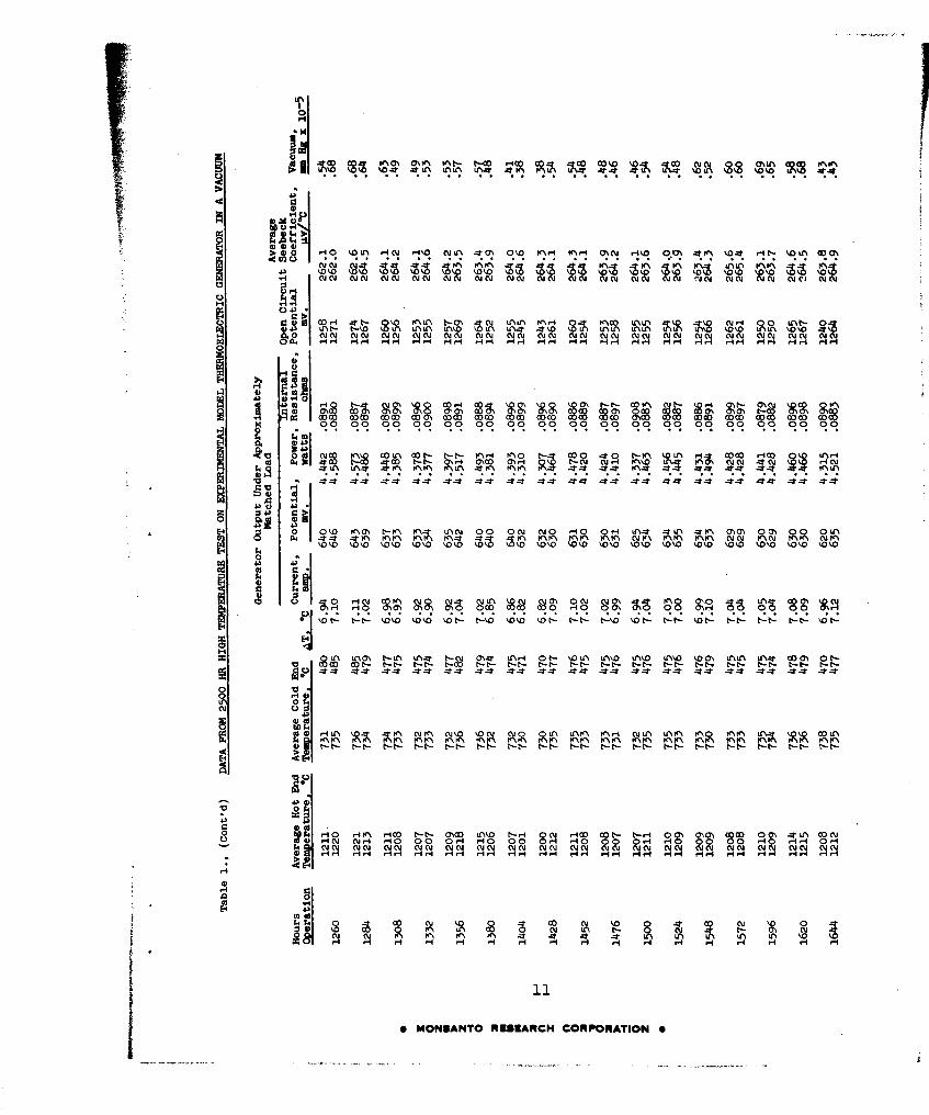
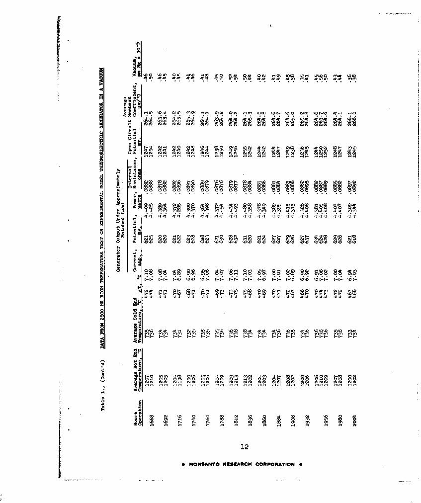
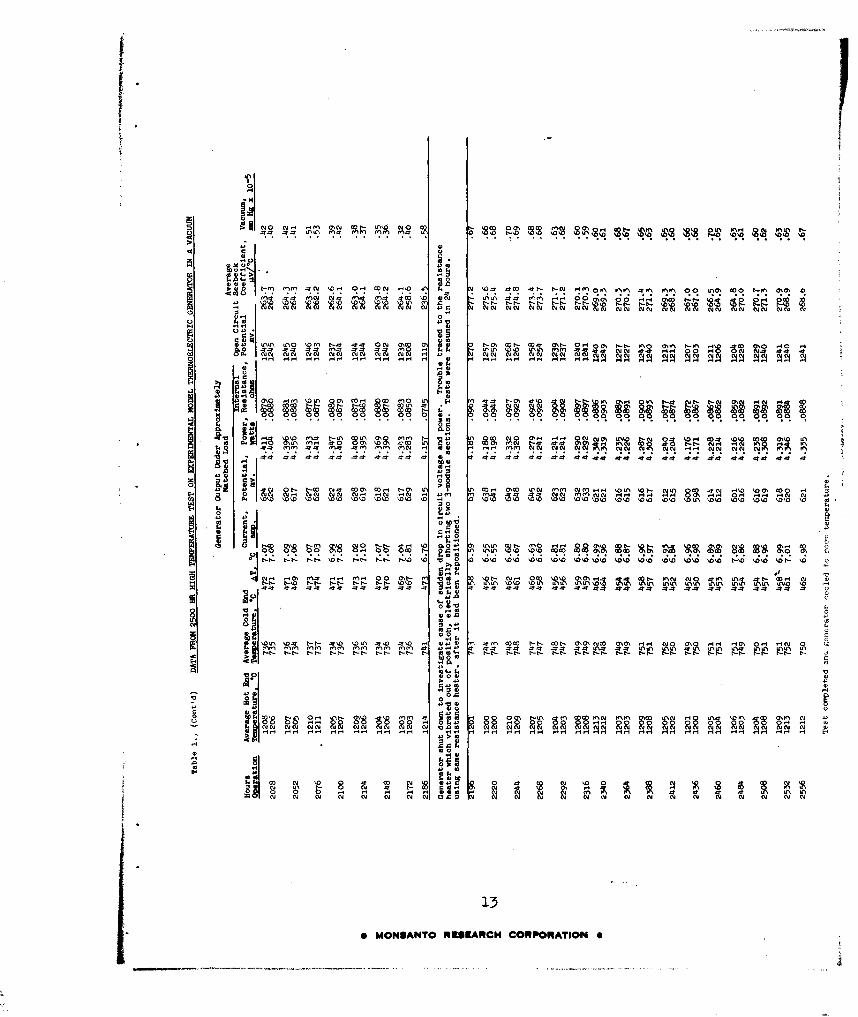
1 Data from 2500-hr High Temperature Test onExperimental Model Thermoelectric Generator ina Vacuum. 8
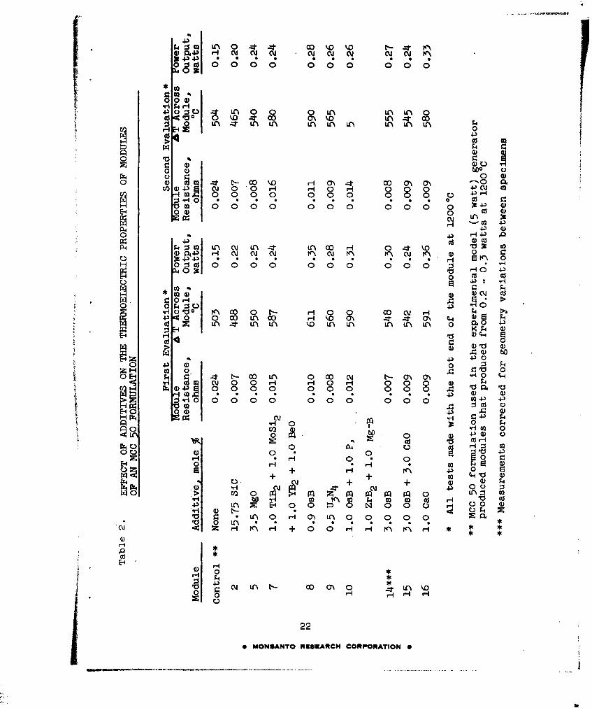
2 Effect of Additives on the Thermoelectric Propertiesof Modules of an MCC 50 Formulation. 22
3 Tests on Graphite-Ended Modules of MCC 60 Modifiedwith Additives. 24
4 Target Values for p- and n-type MCC 40 ThermoelectricMaterials. 25
5 Tests on Graphite-Ended Modules of n- and p-typeMCC 40 26
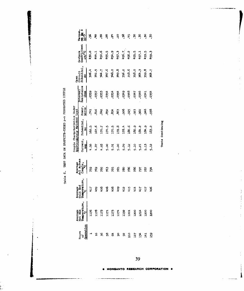
6 Test Data on Graphite-Ended p-n Segmented Couple 39
vi
0 MONSANTO RESEARCH CORPORATION 0
I. INTRODUCTION AND SUMMARY
A. BACKGROUND
The over-all program objective is to conduct applied research toestablish the technical feasibility of utilizing a high temperaturethermoelectric generator with a nuclear reactor heat source toproduce a long-lived power supply for aerospace vehicles. Thiseffort, the second phase of a program initiated 1 October 1961,is directed toward improving and further defining high-temperaturethermoelectric generator components. The results are to be usedto design and fabricate an advanced experimental model of a nominal50 watts output suitable for evaluation by means of electricalheaters or a simulated loop of a liquid-metal-cooled nuclear reactor.
Research on several phases is proceeding simultaneously. Theseare:
Phase I - Experimental Model Evaluation The nominal 5-wattexperimental generator, fabricated and preliminarily testedunder the first year's effort, is being subjected to a sustainedperformance evaluation of 2500 hr with a hot junctio•temperature (Th) of 12000C in a vacuum of 10-9 - 102 mm Hg.The cold junction temperature is about 7000C, dependent uponthe cooling available from radiation to ambient roomtemperatures. The generator is to produce power for anapproximately matched electrical resistance load during thisperformance test.
Phase II - Component Improvement and Evaluation MCC 50,used in fabrication of the 5-watt generator, is availableonly as a p-type thermoelectric material. An n-type material,to supplement p-type MCC 50 in the temperature range of 7000C -1200@C, plus other supplementary n- and p-type materials arenecessary if substantial improvements in thermal efficiencyand other characteristics are to be attained for the 50-wattgenerator. The new materials are to be developed by extendinginformation resulting from the first year's efforts, andalso by use of new proprietary thermoelectric materials.The latter are to be further developed on this project.
Effort will also be directed toward developing techniquesfor producing thermoelectric modules by new junction or end-forming methods. Plasma-arc spray coating the thermoelectricmaterials, as well as the electrical and thermal contacts,will be investigated. In addition, improved formulations willbe screened, with the best formulations to receive a sustainedevaluation.
1
0 MONSANTO RESEARCH CORPORATION 0
Phase III - Advanced Experimental Model The design ofthis generator will be based on results of the first twophases of this project. A 50-watt advanced experimentalmodel is to be fabricated after approval of the design byASD.
B. SUMMARY
The experimental model 5-watt (nominal) generator completed2556 hrs ogeratfon at a Th of 12000C (+25OC-4OC) in a vacuum oflo-5 - 10- mm Hg without degradation of power producing character-istics. Power/weight ratios of 2.7 to 2,86 watts/lb, exclusiveof heater and external circuitry, were obtained. Further testsat 13000C and higher temperatures are planned. The generator isbased on MCC 50, a p-type thermoelectric material, coupled withmolybdenum.
Improvement of proprietary n- and p-type thermoelectric materials(complementary to p-type MCC 50) and methods for joining themprogressed to the point where segmented n- and p-type modules werefabricated and partially evaluated. An initial p-n couple, consist-ing of a graphite-ended segmented module of p-type MCC 50 joinedwith p-type MCC 40 coupled with a graphite-ended segmented moduleof n-type MCC 60 with n-type MCC 40, produced 250% more power at12000C (Th) than the MCC 50-molybdenum couples used in the exper-imental 5-watt generator when operated at the same approximate Thand temperature differential (A T). In addition, an improvedemissive radiator coating was developed which produced an increaseof 400C in theAT in the modules of the experimental model generatoroperated at 12000C Th. Progress was also made in the developmentof plasma-arc techniques for fabricating lightweight junctionsfor use between p- and n-type modules. These developments indicatethat power/weight ratios in the range of 10-20 watts/lb will bepossible for the advanced experimental model generator.
2
0 MONSANTO RESEARCH CORPORATION 0
II. RESEARCH AND DEVELOPMENT RESULTS
A. PHASE I EXPERIMENTAL MODEL EVALUATION
This phase concerns the reliability and durability of the exper-imental model generator. The characteristics of the generator wereto be evaluated by subjecting it to a sustained exposure far 2500 hrsat Th of 12000C (+25oC-4oC) and a vacuum of 10-5 mm Hg. Thegenerator completed 2556 hrs operation this quarter, meeting animportant project requirement. During the sustained performancetest the power output of the generator not only remained stable butactually increased somewhat (--'8%) during the test period.
A cutaway assembly view, with partial cross sections, of the 5-wattgenerator as used for the sustained performance test is presentedin Figure 1. All thermoelectric modules of the 3-module sections1 through 9 around the central resistance heater unit and in the3-module section on top of the generator consisted of 1/2" diameterby 1/2" long p-type MCC 50 elements capped with graphite hot andcold junctions. These modules were joined with molybdenum to formthe basic p-n couple of the generator. Details of module and sectionconstruction are described in preceding quarterlies and the finalreport (ASD-TDR-62-896).
The hot junction temperature was controlled by feeding the outputof the thermocouple located at the cold end of module B of the3-module section 5 of Figure 1 to a power and temperature monitoredcontrol system shown in the circuit diagram of Figure 2. Thermo-couples were located at three hot-end sites and five cold-end siteson five different 3-module sections, in order to obtain represent-ative hot and cold temperatures of the generator under the test.The output of all temperature sensing thermocouples, generatorcurrent, and voltage outputs were continuously recorded. Through-out the test, the generator output, as indicated in Figure 2,was series-connected with a closely matched external resistive load"R" for maximum power output.
Prior to the 2500-hr test, the experimental model was subjectedto more than 100 hrs of continuous operation and for 106 thermalcycles. These tests are described in the final report for thefirst year's work, ASD-TDR-62-896. After these tests and beforeinitiating the sustained performance test, the experimental modelwas disassembled, inspected and reassembled. Close examination ofeach of the modules, ptior to starting the sustained performancetest, revealed no evidence of deterioration or physical damage(e.g., cracking) to the carbon-MCC 50-carbon modules. The molybdenumwire leads were also unaffected. The thermal insulation used toreduce the heat losses between the modules was discolored and some-what embrittled, but seemingly functional. New insulation wasused in the reassembly. It was noted that reinsertion of themolybdenum lead wires into the hot junction shoes of each three-
3
* MONSANTO RESEARCH CORPORATION S
0 H
r-1 04
04-'
4-) Q)
40 c
U)-
(L)O
0r10
H H Or
r. 0H
;_4 0 o
4) co
4-)
x 0),
4-).
4- c* ~ ~ ~ ~ ~ ~ ~ ~ -MOSNOREER4CRPRTO
coA

0
.5C --
lo 0
-0 0 S
= ur. 0 -
oo 0 -
0 0
U 'U 0
00
rz co
PC)
0 OSNOUEIAC OPRTO
module section caused a slight loosening of the fit between thewire and the hole in the graphite sections.
To offset an expected decrease in power output resulting from thissomewhat loose fit between the molybdenum wire leads and the holesin the graphite section pieces, a tenth 3-module section was-addedin series with the nine 3-module sections used in the originalgenerator. Thus assembled, and as shown in Figure 3, the experi-mental model generator weighed 1.6 lbs, exclusive of heat sourceand external lead wires.
The environmental vacuum chamber and auxiliary apparatus used tomonitor generator performance during the 2500-hr test was describedin the lcurth Quarterly Progress Report, pages 6-7.
Target conditions and data to be accumulated for the sustainedperformance test were as follows:
1. Hot-end temperature of about 12000C.2. Cold-end temperatures dependent upon radiation cooling.3. Vacuum of 105- mm Hg.4. Operation under approximately matched load conditions.5. Environmental and operating conditions plus load voltage
and current data to be recorded at least once each 24-hrperiod.
Data from the 2556 hrs test, during which at least two sets ofdata were collected for each 24-hr operating period, are presentedin Table 1. Figure 4 is a plot of the data in Table 1. After someinitial variations of power output, caused by small fluctuationsof hot-end temperature, the power output of the generator slowlyincreased with time until at about 800 hrs it was 4.362 watts ata Th of 12140C and a AT of 4870C. This is approximately 8% morepower than the 4.031 watts (2.5 watt/lb) the generator deliveredat the start of the test and correspondt to a 2.7 watt/lb ratiorofpower output to generator weight. The generator output continuedto increase slowly with time until at 1260 hrs operation the outputwas 4.588 watt at a Th of 1220'C and a aT of 4850C, for a 2.86watt/lb ratio and an approximate 14% improvement in generator out-put. Operation from 636 hrs to 2186 hrs was uninterrupted byheater trouble, the cause of six generator shutdowns during thefirst 636 hrs of the test.
A sudden drop in generator output voltage and power at the 2186thhour was traced to short circuiting of 2 or more of the 3-modulesections by wires from the heater unit which apparently had vibratedloose from its moorings and leaned against the hot end of thegenerator. This trouble was cured by cooling the generator to roomtemperature and repositioning the heater. No further heater orgenerator trouble was encountered and the generator output remainedrelatively constant to the end of the test. After 2556 hrs operationthe generator output had reached a plateau of 4.335 watts at 12120CTh and a AT of 461 0 C. It is believed that this improvement of 8%
6
0 MONSANTO RESEARCH CORPORATION 0
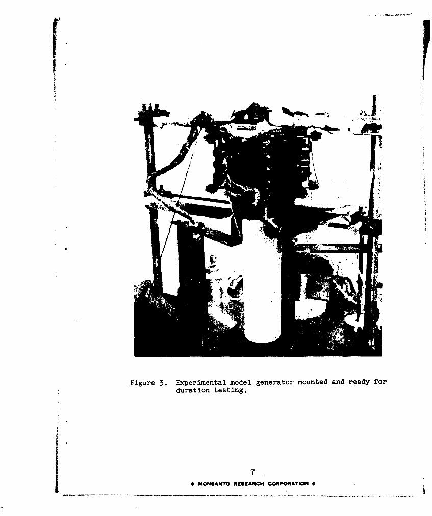
Figure 3. Experimental model generator mounted and ready forduration testing.
7
S MONSANTO RESEARCH CORPORATION S
*IM
4r 4 .r4 4 :T(4 44 r-V 4:t*A
cu N aIc u C v c u c u NN C u c u u %N C Y c u c Y0 uC u
0 0-t 0 " 0'U
IL.I
S4 i
4) PC N^ 110
I& OD o 8 p9o " c
C! ff 'c 8(0 00 ~ ~ 0 ("(-'~' (0 '(0 'O' 8C" -0' .0" 00' '%''OO
0*J0441.
0 0 c
14
im 4)3 ?C\ ')- 0.4 LAR H)'. m. FI- (40 4O )0 04')0E-4 c II - t-r ý Uc *t N 4
44
010
044 ~0
88
4~~ ~ MOMAT Ru0UEARrHCn([ Dcj -Dt-ý H CORPOXTION kD* n 0 -

too.0 t -Io 0*- 0; .4 4H 44 (m" 4n" 4 LA?" UAN V% 44Ný %0 44 Lr
cu ~ N N N NNN N N NNi Nucicj C N N N NN N N co Nu e.JN YC c t w Yc c
00 0r 80 00N 00 KN00 M 00 0 0 00 00\ 0'^ 0 00\ 00 001 %c % 4r-ml\ 4(
00 q 0 H 0 -I rNN r r-4 H 14 H g- f 4Hr 4H ý
-c. mA LAD M~~ WO LA,4-$ O L\ 0 N L0L Na 00( .44 OLAO 14 U, t-%D OLn~~r- c
'. M HD1 m1h MMC0O10 \ M000 0 0 0 !C 0 0~ 103 '0 '1'00 00 0 ~U00~' 00 010 11 0D
0 443 0
43LA LA LAL (m NNALA 0
141 v-- 4-t 44 gLAN- -
.44 0.0
m N N HN Nu N N.4 NN NH- .4. cN N4 NN NN NN NNml
\0 IDN -44 L* kL 410 10L 40 % 0 0O G4 - .0 4 t~ %D -t k-- LAO IL'.?".0 0 \".O" rk'?L' 104 kF0
43)
93 .0
4)0Ln 1r3 4-
E-4 09
6s MOSAT REEAC CORORAOO m0 - e
A AI
Cý-I- COO 1-Ln %00 CY0 01*V .41 WN ^O 1-0 001 G$^ &A^~ ý00 CYO0 LAkd' ' Ln^ tL'10
4Z Z 4 Z OLO' 6N A % kni O' Z I909
C.CD
RI !R9C RHff I OOO 00
oy~ ~ ~ ~ ~ ~ 9 A9ORnr4HRRW^rAi 91 A . mtArt
KI CVo .' 00 0 . .. .
%D0 01 014 o) 01 am W KK ot e& S&~4 8^C! C!
01 -0101 D W11 0 11001"H01 HCr'
04.0 Im H H H a%~ 0 H' Iý-C- 4nL 0w tC-W t-0m 00 0t.'0 '0O -C
o '40 9'4 00 8 4' -' 44 ''
'-4 rq ro:i
10t e~~~~ MONSANTO RESEARCH OPNIN0
14 447,~
A 0IA ~ J 0 L~
4)* 0 0C J H (ow K~n t-m' I t Lo\H ol h%000 0 L'-' 'CLA M4 N H 0 0 n t. -
40. H,' H H H H HH H'. H' H' e1.-4 H '. tA4 H m H 14 H ý8 -4
4 0 4 * 04 4 * * * * * 4 * * 4 4 4 4 * 4
0ýra '4 E- t~CM ta \ ko O 00 001 -1 w \ 0 m~ t-4 t-- UCD I". H 8 4 t- 0\c 0
v 0 a- 01.01 01.z 011P. a0010' .Dc c DC 00 0100. 2 23 WS OD OD 00 D000\.
0 44cd 09 -T LAO'. _-LA t.- .- mm \r.4* RID O t.- 'C. C'.' LA' K A'C '00' IALA LAS (00'. 0c 4 cu os
*4z 4* 44 4 4 -- t 4~ -t -T4 -T 44 44 4~t4 44 at 4T-t4 44 -T 4t4. -t-
40 'a
43E-4) o -L 01o P0%a1- \-N u\c 0 cu LAm ' 0 r-4 H (v*r'. LA?"' 1". 'm 0 w
5 4 _ 0* 4W\ PC\ "' n1' n'Cj \ K N K\ "\ C % K m m K l
44 4ý
to4 m 0 %C Y-. mU\ý8 C c m c %S9 t\8 01 - n c
IDt . - I D* . k - t% 00 0I- t t- t% 0t -t Dt- -t . l -t 0t
'003
H
Ul 0
1.11
go MO4AT r4EAC CORPORATIOn kl ý N0 U% ' K N n " \ " D 0 Ar
-4
04.
AO 0
M* M11V L U' Lf'4 Mr4 * L~ *
0 1 144 1 '. H 4 HH rl H r-4r4 -l 4 r,4 14 4 4r.,r1 Cr1 ý4L A H * .4 r4 r44
0 0.40 C00 01W 0 t-O ONOM '00 Oý -M O t--l .4o NrC 0L0t-l~1ONCO
§( 000
O 0 OoL 0I 01LC 00 CO () r
f CA N s tw 001M CD M-C 0N 001 CLn t-r COD M -I,- 010 W 00 00 0
.am 0*
4 -I Ln 00 0 H C C M ODn M H0 001 N -10 HA SID t- w M0COo 01111100000 N 0NN N1INN N MNM M A 04C1cr0 01110 N 01-I9 14 .kow '0. % 10 '.01 %D0 'Ol %0110 D0.D 'D1 IID I o % D kk k kD k 0 ID 10 10 %0
010
LAID c CrCr Cstl 0LID n H on ot I lL -~Ik-0- O-k- 6-k- 8 M-- H-k- O-M- k-k- gk k-N- k-k- k-k- - 8sk &Mk- --
cv-M ()l
8 H
U)0cu 0
0) r-r 4H Nn U 'ý n O * - - W % w W % n -MMK) M M M M M M M M M M M M M
y%0 0OSAT RSACHj CORPORATION
*'\ cK\ 00 NAO co t.- OOd 0 0
-. 0t0 t-
00U
H- 10 0, 00. MO W E0n
0.10
0 . , a
100
c: ( 44PIC 4 4( 4 4 - 0 0 45 4 CC-4. 0014 51 -. O 01 4- ls 0- 44)(5 III 4 ~ * 4 4 4 4 ~ ~ ~ * ~ g
C-- ---- C--- C--- C-C- -C C-C- 00 CC-0o C C-'D -- -- C -- CC- CC- C-- -. -- -- C--0.1 0 o m H cfoq-. 99
vo0
B0&A00t .tý ',t* t*t- , - tw ' 0 0, o 00 %ý ~ DD t 04 a% oD ýt 00 ý% -w WD I -
Ha m1~ H4. MH 90 - m. aI. 10 t- 61.- H-,- Q-Ir 9-1.- S49 I A p4.- - al 0-1A- Na -p4 C
-v o
CC.
0 z
t.4 t 0t .- t- r - tt - t- 9-I t- r10.
WN N p N CII N CII Ny 8 'R 9w0 N N N Ný NNl
0' MONAT RC4AC COPOAIO
0
02
ca
02
MI 0
co 4
m, H
0104
H02
- - - -.
i ~~I OWNI -'9 .J-
___o_ __-_
9. •-••#, "'i " "su; '
14
,_ •~ MONSANTO RUrSIARCMH CORPORATION S
W
I W
;K4)
c 0
_ . al
0.
;4)0
co
'04-) r
II
'0
15
S MONSANTO RUEIrARCH CORPORATION S
- 4)
I
I
a0)
co 0
S 4~W
51
4oo~O co 0
0a
161 1600Sr-6 I
O hCLL
1-.60 MONSANTO RmrllrARCH CORPORATION 0

in generator output with time resulted from the gradual loweringof resistance of the Junctions between the modules with time atelevated temperatures in a vacuum. Some improvement in thermo-electric properties of MCC 50 with time may also have occurred.
Examination of the exterior of the generator, at the end of thek test, revealed no damage from sublimation, thermal cracking or
diffusion damage of its MCC 50-molybdenum couples. Figure 5, aphotograph of the generator taken at the end of 2556 hrs exposureto test conditions, may be compared with Figure 3 (at start of test).The exterior of the modules and other generator parts were notvisibly affected,, other than a darkening of the Fiberfrax insulation.This darkening,previously noted during the 100-hr test last year,apparently has little effect on the thermal and electrical propertiesof Fiberfrax.
Following completion of the sustained performance test, attemptswere made to determine whether a graphite-phenolic radiator coatingwould increased T's along the generator modules. Attempts werealso made to measure drift of the control thermocouples during the2556-hr test period. The emissive coating evaluation showed thatits use on the advanced model should produce an increase of atleast 400C above the A T's obtained on the modules of the experimentalmodel generator. Details of tests on the emissive coatings arepresented in section II B 3 , Emissive Coatings.
To determine the possible change (drift) of the thermocouples in2556 hrs exposure to vacuum and high temperature, careful attemptswere made to remove the test-worn thermocouples so that theiremf output could be compared with the output of new calibrated ones.Unfortunately, none of the tungsten-rhenium couples used formeasuring Th could be removed intact. When it was found that theold thermocouples were so fragile, a new one was carefully installedin place of the first couple and the generator returned to operationat a Th of 12000C. This procedure permitted comparing the emf'sof the used tungsten-rhenium couples against the new one. Thissort of a comparison was made again after a second hot-end thermo-couple was replaced, permitting comparison of the Th of the generatorwith two new couples and one of the original couples. These testsindicated that the maximum drift of the tungsten-rhenium coupleswas less than + 100C at 1200 0 C after 2556 hrs.
After conducting Th thermocouple drift evaluation tests on theexperimental model generator, two of the cold-end thermocoupleswere removed intact. These will be compared against new ones todetermine how much their calibration may have drifted during thesustained performance test.
If time and project scheduling permit, it is planned to operatethe experimental model generator in a vacuum to temperatures of13000C for 500 hrs. If the generator survives this test, thetemperature will be increased to 1350 0 C.. If it survives the 1350 0 Ctest, the temperature would be increased to 14000C. Prior to
17
0 MONSANTO RESEARCH CORPORATION 0

Figure 5. Appearance of experimental model ~enerator after2556 hrsoe posure at a Th of 12000C in a vacuum ofib-5 - ri~ m Hg.
18SMONSANTO R6SEtARCH CORPORATION 0

Radiator Radiator
3rd Junction 300 *CV
p-type MCC-40 n-type MCC-40
2nd Junction 700 'C
p-type MGG-50 ' -type MCC-60
1st. Junction 1200 *C Carbon JunctionCarbon Connector
Figure 6. Proposed arrangement of segmented p- and n-typematerials for use in an advanced experimentalmodel generator.
19
e MONSANTO RKIEARCH CORPORATION e
-~-.-----~--.--------.

starting the 13000C test, the worn tungsten heater unit will bereplaced with a new one. At that time, a partial inspection ofthe generator will be made. These plans were made in cooperationwith the project engineer.
B. PHASE II COMPONENT IMPROVEMENTS AND EVALUATION
The purpose of this phase is to provide the improved materials andtechniques necessary to meet the design goals for an advancedexperimental model thermoelectric generator capable of a nominaloutput of 50 watts, 6 volts, 7% efficiency, 20 watts/lb with lessthan 10% degradation when operating at temperature for a 1-yearperiod. Operating conditions are to be: a hot junction temperatureof 12000C and cold Junction temperature obtained by radiationcooling in a vacuum of 10-5 mm Hg. The 50-watt unit should alsoaccommodate one or more 12" long x 7/16" diameter heat scurcesrepresenting a portion of a hot liquid metal loop from a nuclearreactor heat source.
To achieve these goals, matching and improvement of the thermo-electric properties of new materials, originated by Monsanto ChemicalCompany (MCC) to supplement MCC 50, are needed. In addition,segmenting of these new materials in p-n couples, as illustratedin Figure 6,was proposed.
The three supplementary MCC thermoelectric materials to be investigatedin addition to improving MCC 50 under this phase of the projectare:
1. n-type MCC 60, a new proprietary thermoelectricmaterial useful to 1200-1500°C and so far the bestcandidate material for use with p-type MCC 50.
2. n- and p-type MCC 40, new materials useful at temperaturesbelow 8500C.
To improve the power/weight ratio and efficiency of the advancedexperimental generator, a radiator coating of improved emissivity(relative to the nickel oxide coating on the radiators of the5-watt generator) is needed. Additionally, improved junctionforming techniques to permit fabrication of the segmented typemodules shown in Figure 6 of low interface resistances and goodmechanical properties, are needed. Waste heat radiators integrallyjoined to segmented modules are also needed. Arc-plasma techniquesfor forming such radiators and for producing large doughnut orring-type modules to minimize generator heat leaks are to beinveetigated.
Preferably, all candidate improvement formulations would bescreened in module form. However, the effort required to matchand bond junction materials with improved thermoelectric formulations
20* MONSANTO OWSEARCH CORPORATION S
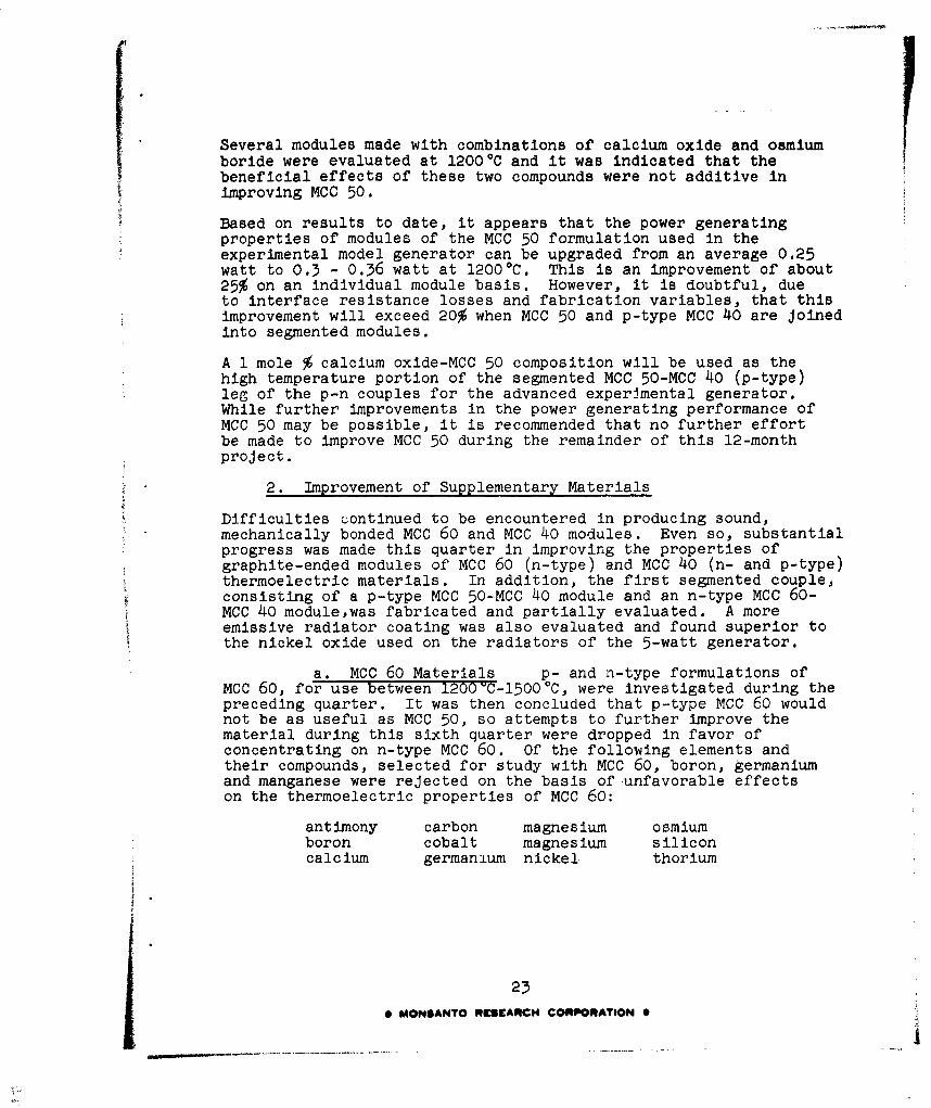
was clearly beyond the scope of this project. As described onpage 14 and in Figures 6, 7 and 8 of the Fourth Qparterly ProjectReport, special apparatus was designed and fabricated for screeningthose hot pressed elements (without junctions) of thermoelectricmaterials not readily fabricated as modules (with thermal andelectrical Junctions). Apparatus used to evaluate materials inmodule form was described on page l4 and in Figures 8, 11 and 12of the Fourth Quarterly Project Report. Both types of apparatuswere capable of evaluating materials under the same vacuum (10-5 -10-6 mm Hg) and temperature (-12000C) conditions.
Details of the work completed under this phase of the project arepresented next.
1. Improvement of MCC 50
During the preceding quarter, the effect of additives on the thermo-electric properties of MCC 50 was further evaluated using a moduleof MCC 50 as the standard. Eighteen modules were fabricated andscreened using this MCC 50 formula, modified with various additivesand combinations of additives, selected from prior data (Table 3of the Fburth Quarterly Report. Of this group, 9 showed sufficientpromise of improved thermoelectric properties to merit furtherconsideration. Additional modules of each of these formulationswere made and subjected to a second evaluation. The results ofeach evaluation of these modified MCC 50 formulations are presentedin Table 2. As shown in this table, results for each module werein all cases better than the MCC 50 formulation module used asthe standard in these evaluations. Modules containing osmium borideand calcium oxide additions offered the most immediate promisefor improvement in the power generating properties of MCC 50.
Accordingly, further efforts were made to determine the effectsof osmium boride and calcium oxide as individual additives and invarious combinations of the two. Modules were made from thestandard MCC 50 formulation at six different levels of calciumoxide addition: 0.1, 0.3, 0.5, 0.7, 0.9 and 1.0 mole %. Poweroutput per module ranged from a high 0.36 watt at 1.0 mole %calcium oxide to a low of 0.260 watt at 1.1 mole % calcium oxide.All measurements of module properties were made in a vacuum witha hot junction temperature of 12000C and using the same radiatorto cool the cold junction.
Modules were made using seven levels of osmium boride addition:0.1, 0.3, 0.5, 0.7, 0.9, 1.0 and 1.2 mole %. The same standardMCC 50 formulation was used for this osmium boride series of modulesas was used for the calcium oxide series. Power output per modulefor the osmium boride series ranged from a high 0.3 watt at 0.9mole % osmium boride to a low of 0.20 watt at 0.1 mole % of theboride.
21
*MONSANTO RESEARCH CORPORATION0A
8.1
0 * . 0 *
43 0 0):3 8 0 0s 0 0n 0 0n 00
0000.4.10 A 0.)
H4 U
0 a boo UN U 0 0)
0 0 9'm 4 ý '0 H- (3) 4t 00 m7 ch - Q) -,AC\J 0 0 H HOI 0H- 0 00 4.)CU m
0- 0 0 0 0 0 0 0 0 0 0 U0-
00I c; LA c; c ; c; '0
H 41 40 .43 r H.P Q0
4.) ~ C14.). rOI LA I (\ CU 0A A 0 .
K041 H C U C \ (\I r~1 K\ cm KN 0 0
H ; 0 ; 0 ; 0; 0 00 0 00 .rHO4.0 - 0 -
0 048~ 0~ 0- H0 0 0,O C HF.0 ~ ~~~ Lo CO H '0 ' 4 0
H O r ). $ý0 HO C; II0H 0 04: .
OE-4 .
00
E0 00) 4.
Z H 4n.)
ca~~Q I N+ - - 0) 0 4CU :ý 0 0 0. 00 0- 00 ) 4
1:03-1 tCiI 0~ 0 0 C; H; c ; c ; c4.) 0 LA E(00L0N 0 0 )
V~- 00A 0 * * * *
0 *
0. H PH H C
0 MO0AT RUEAC COaRTO
_________ ____ 4 $
Several modules made with combinations of calcium oxide and osmiumboride were evaluated at 1200 0 C and it was indicated that thebeneficial effects of these two compounds were not additive inimproving MCC 50.
Based on results to date, it appears that the power generatingproperties of modules of the MCC 50 formulation used in theexperimental model generator can be upgraded from an average 0.25watt to 0.3 - 0.36 watt at 12000C. This is an improvement of about25% on an individual module basis. However, it is doubtful, dueto interface resistance losses and fabrication variables, that thisimprovement will exceed 20% when MCC 50 and p-type MCC 40 are joinedinto segmented modules.
A 1 mole % calcium oxide-MCC 50 composition will be used as thehigh temperature portion of the segmented MCC 50-MCC 40 (p-type)leg of the p-n couples for the advanced experimental generator.While further improvements in the power generating performance ofMCC 50 may be possible, it is recommended that no further effortbe made to improve MCC 50 during the remainder of this 12-monthproject.
S2. Improvement of Supplementary Materials
Difficulties continued to be encountered in producing sound,* mechanically bonded MCC 60 and MCC 40 modules. Even so, substantial
progress was made this quarter in improving the properties ofgraphite-ended modules of MCC 60 (n-type) and MCC 40 (n- and p-type)thermoelectric materials. In addition, the first segmented couple,consisting of a p-type MCC 50-MCC 40 module and an n-type MCC 60-MCC 40 module,was fabricated and partially evaluated. A moreemissive radiator coating was also evaluated and found superior tothe nickel oxide used on the radiators of the 5-watt generator.
a. MCC 60 Materials p- and n-type formulations ofMCC 60, for use between 1200=C-l500°C, were investigated during thepreceding quarter. It was then concluded that p-type MCC 60 wouldnot be as useful as MCC 50, so attempts to further improve thematerial during this sixth quarter were dropped in favor ofconcentrating on n-type MCC 60. Of the following elements andtheir compounds, selected for study with MCC 60, boron, germaniumand manganese were rejected on the basis of unfavorable effectson the thermoelectric properties of MCC 60:
antimony carbon magnesium osmiumboron cobalt magnesium siliconcalcium germanium nickel thorium
23
* MONSANTO RESEARCH CORPORATION 0
JI

Forty-two modules of MCC 60, modified by various combinations ofantimony, calcium, carbon, cobalt, magnesium, nickel, osmium,silicon and thorium or their compounds (largely oxides), were madeand compared for power generation output in a vacuum at ~ 12000C.Compounds of calcium, thorium, silicon and cobalt produced themost promising n-type MCC 60 modules. Only modules with theseadditives produced more than 0.01 watt with a Th of 1200 0 C, theminimum power output considered worthy of further study. Table 3presents data on the MCC 60 modules that passed this screening test.
On the basis of this work, and in conjunction with the projectengineer, it was decided to forego further studies of the effectof additives based on antimony, carbon, magnesium, nickel and osmium.Compounds of these elements showed little promise of upgrading n-typeMCC 60 beyond an 0.02 watt le',el.
Concentrated effort to improve n-type MCC 60 with the silicidesof thorium and cobalt in combination with calcium oxide resultedin module 16P of Table 3. It produced 0.08 watt, the highestpower output for a MCC 60 module produced to date on this project.
Based on the performance of module 16P, n-type MCC 60 should beused above 8500C and our previous target of 0.2 watt at 12000Cfor a AT of 5500C should be revised to 0.1 watt at 12000C for a&T of 3500C. MCC 40 (n-type) modules, which are appreciably moreeffective than MCC 60 (n-type), would be used in segmented modulesat temperatures of 8500C and lower. The actual A T, over whicheach segment of thermoelectric (MCC 50, MCC 60 or MCC 40) materialshould operate to produce the most power per unit of weight inthe advanced expeririental model generator will be determined bytrade-off studies of Joule heat losses, thermoelectric propertiesof module materials, and radiator characteristics.
Table 3. TESTS ON GRAPHITE-ENDED MODULES OF MCC 60 MODIFIED WITH ADDITIVES
Seebeck Module AT AcrossModule Additive, Coefficient, Resistance, Module, Power,
No. mole %. ývC ohms 0C watts1 4.9 CoSi; .5ca -120.4 01017 52b 0.05
0.5 ThSi2; 0.1 Sb*16D 2.0 CaO -148 0.0734 470 0.022*16E 3.0 CaO -119.4 0.0456 447 0.021
16F 4.0 CaO -113.8 0.0178 459 0.079*16G 5.0 CaO -183.8 0.0706 460 0.025*16H 5.0 CaO; 5.0 CoSi -98.07 0.0226 437 0.029*16J 3.0 CoSi -77.7 0.102 476 0.031
16K 5.0 CoSi -39.0 0.0436 513 0.01016L 1.0 ThSi2 -86.1 0.0679 569 0.019116M 3.0 ThSi 2 -30.1 0.0082 428 0.042*16Q 1.0 As, i.0 CaO -120.7 0.0590 420 0.015
16R 1.0 Ca0; 1.0 CoSi,-71 0.010 429 0.081.0 ThSi 2
*Tested as thermoelectric element without junctions.
24e MONSANTO RESEARCH CORPORATION 0
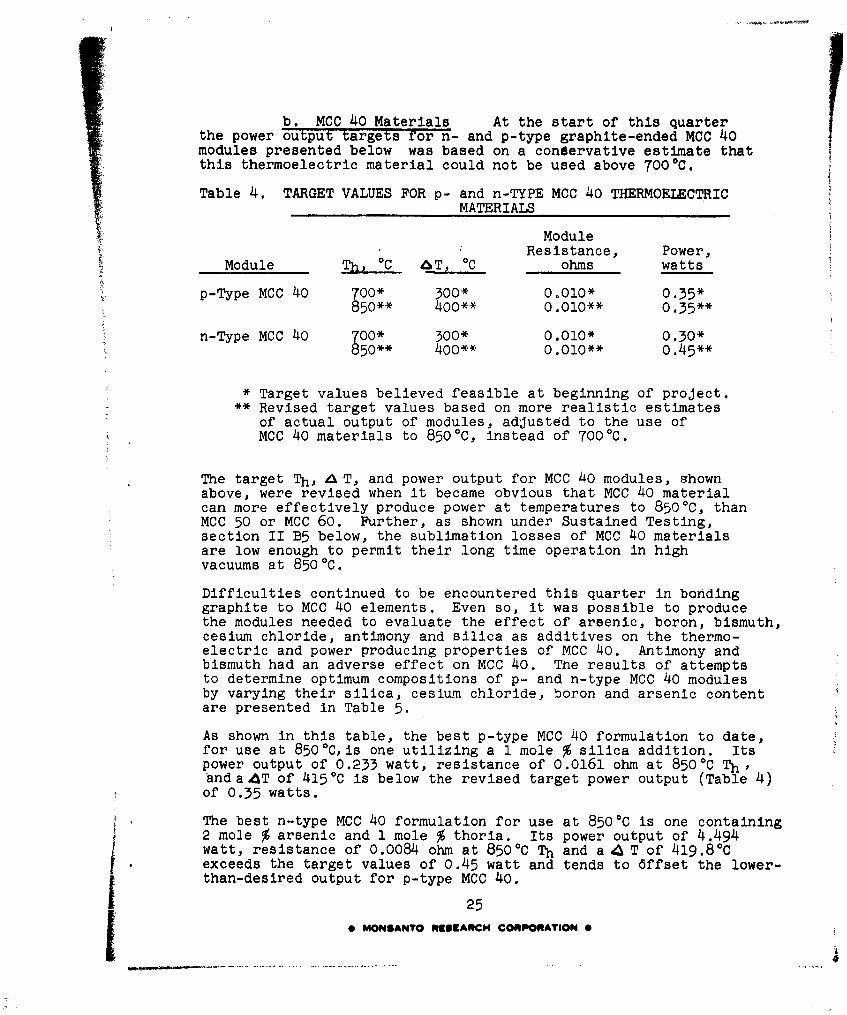
b. MCC 40 Materials At the start of this quarterthe power output targets for n- and p-type graphite-ended MCC 40modules presented below was based on a conservative estimate thatthis thermoelectric material could not be used above 700 0 C.
Table 4. TARGET VALUES FOR p- and n-TYPE MCC 40 THERMOELECTRICMATERIALS
ModuleResistance, Power,
Module C C ohms watts
p-Type MCC 40 700* 300* 0.010* 0.35*850** 4o0** 0.010** 0.35**
n-Type MCO 40 700* 300* 0.010* 0.30*850o** 400** 0.010** 0.45**
* Target values believed feasible at beginning of project.** Revised target values based on more realistic estimates
of actual output of modules, adjusted to the use ofMCC 40 materials to 8500C, instead of 7000C.
The target Th, , T, and power output for MCC 40 modules, shownabove, were revised when it became obvious that MCC 40 materialcan more effectively produce power at temperatures to 8500C, thanMCC 50 or MCC 60. Further, as shown under Sustained Testing,section II B5 below, the sublimation losses of MCC 40 materialsare low enough to permit their long time operation in highvacuums at 8500C.
Difficulties continued to be encountered this quarter in bondinggraphite to MCC 40 elements. Even so, it was possible to producethe modules needed to evaluate the effect of arsenic, boron, bismuth,cesium chloride, antimony and silica as additives on the thermo-electric and power producing properties of MCC 40. Antimony andbismuth had an adverse effect on MCC 40. The results of attemptsto determine optimum compositions of p- and n-type MCC 40 modulesby varying their silica, cesium chloride, boron and arsenic contentare presented in Table 5.
As shown in this table, the best p-type MCC 40 formulation to date,for use at 850 0C,is one utilizing a 1 mole % silica addition. Itspower output of 0.233 watt, resistance of 0.0161 ohm at 8500C Th,and a AT of 4150C is below the revised target power output (Table 4)of 0.35 watts.
The best n-type MCC 40 formulation for use at 8500C is one containing2 mole % arsenic and 1 mole % thoria. Its power output of 4.494watt, resistance of 0.0084 ohm at 8500C Th and a 4 T of 419.80Cexceeds the target values of 0.45 watt and tends to 6ffset the lower-than-desired output for p-type MCC 40.
25
0 MONSANTO RISEARCH CORPORATION 0
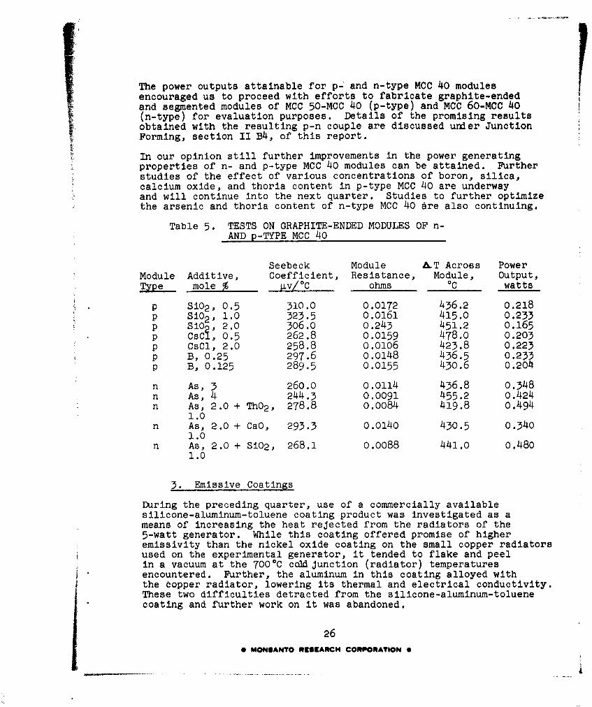
The power outputs attainable for p- and n-type MCC 40 modulesencouraged us to proceed with efforts to fabricate graphite-endedand segmented modules of MCC 50-MCC 40 (p-type) and MCC 60-Mcc 40(n-type) for evaluation purposes. Details of the promising resultsobtained with the resulting p-n couple are discussed under JunctionForming, section II B4, of this report.
In our opinion still further improvements in the power generatingproperties of n- and p-type MCC 40 modules can be attained. Furtherstudies of the effect of various concentrations of boron, silica,calcium oxide, and thoria content in p-type MCC 40 are underwayand will continue into the next quarter. Studies to further optimizethe arsenic and thoria content of n-type MCC 40 are also continuing.
Table 5. TESTS ON GRAPHITE-ENDED MODULES OF n-AND p-TYPE MCC 40
Seebeck Module &T Across PowerModule Additive, Coefficient, Resistance, Module, Output,Type mole % Lv/ 0 C ohms 0C watts
p Si02 , 0.5 310.0 0.0172 436.2 0.218p Si02 , 1.0 323.5 0.o161 415.0 0.233p Si02 , 2.0 306.0 0.243 451.2 0.165p CsCI, 0.5 262.8 0.0159 478.0 0.203p CsCl, 2.0 258.8 0.0106 423.8 0.223p B, 0.25 297.6 0.0148 436.5 0.233p B, 0.125 289.5 0.0155 430.6 0.204
n As, 3 260.0 0.0114 436.8 0.348n As, 4 244.3 0.0091 455.2 0.424n As, 2.0 + ThO2 , 278.8 0.0084 419.8 0.494
1.0n As, 2.0 + CaO, 293.3 0.0140 430.5 0.340
1.0n As, 2.0 + Si02, 268.1 0.0088 441.0 0.480
1.0
3. Emissive Coatings
During the preceding quarter, use of a commercially availablesilicone-aluminum-toluene coating product was investigated as ameans of increasing the heat rejected from the radiators of the5-watt generator. While this coating offered promise of higheremissivity than the nickel oxide coating on the small copper radiatorsused on the experimental generator, it tended to flake and peelin a vacuum at the 7000C cold Junction (radiator) temperaturesencountered. Further, the aluminum in this coating alloyed withthe topper radiator, lowering its thermal and electrical conductivity.These two difficulties detracted from the silicone-aluminum-toluenecoating and further work on it was abandoned.
26* MONSANTO RESEARCH CORPORATION 0

Experiments with various suspension agents led to a graphite-phenolic varnish base coating having promising emissivity (on arelative basis) and good adherince on copper metal. This material,diluted with ethyl alcohol, could be painted on the-radiators andrequired only air drying for 24 hrs followed by a low (50-200 0 C)temperature bake of 2 hrs in air or an inert atmosphere. From thetest results (using a simple comparator flowmeter), it was predictedthat this coating would produce an increase of 30-60C in thetemperature drop across modules mounted in the 5-watt generator.
After completing 2556 hrs operation on the experimental generator,it was decided to determine the effect of this coating on the ATacross modules of the 5-watt generator. This could be accomplishedmore meaningfully by applying, curing and testing the coating inplace on the radiators of the generator. The graphite-phenoliccoating was applied directly over and cured on the nickel oxidecoated radiators of the generator, with extreme care to preventany movement of the thermocouples in the hot and cold end of thegenerator. After completion of the coating operation the generatorwas returned to a steady Th of 12000C. When thermal equilibriumwas again achieved,the temperature drop down the length of themodules of the generator had increased by 400C above the AT obtainedwith the original nickel oxide coated radiator. On the basis of200-300 hrs exposure to a radiator temperature of -700 C in avacuum of lO-5 - lO-6 mm Hg,the graphite-phenolic coating has shownno appreciable loss of radiating power. It has shown a slighttendency to blister when it was heated too rapidly in a vacuumimmedietely after application, but this problem should be minimizedwith a more gradual vacuum bakeout cycle.
Determination of an increase in generator output with the increasedA T available from the graphite-phenolic coating was not possibleas the tungsten heater once again short circuited several of the3-module generator sections.
Specimens of this coating have been submitted to ASD for quantitativeemissivity measurements to ~7000C in a vacuum. The emissivityof other specimens will be measured under an inert atmosphere to*,600OC. Emissivity of this graphite-phenolic coating will alsobe compared with a high emissivity (0.88 at 7000C in a vacuum)coating known to ASD.
4. Junction FormingTo obtain design data the fabrication of four segmented moduleswas attempted late this quarter. These modules consisted of MCC 50-MCC 40 (p-type) and MCC 60-MCC 40 (n-type) materials joinedtogether and capped on each end with graphite. One module failedduring hot-pressing and one was broken during attempts to equip itwith thermocouple holes after being successfully hot-pressed.
The procedure used to fabricate these initial segmented p-typemodules consisted of hot-pressing 5 g of MCC 50 powder in a boronnitride-lined graphite die between two graphite (type AUC) end plungers.
27* MONSANTO RESEARCH CORPORATION 0
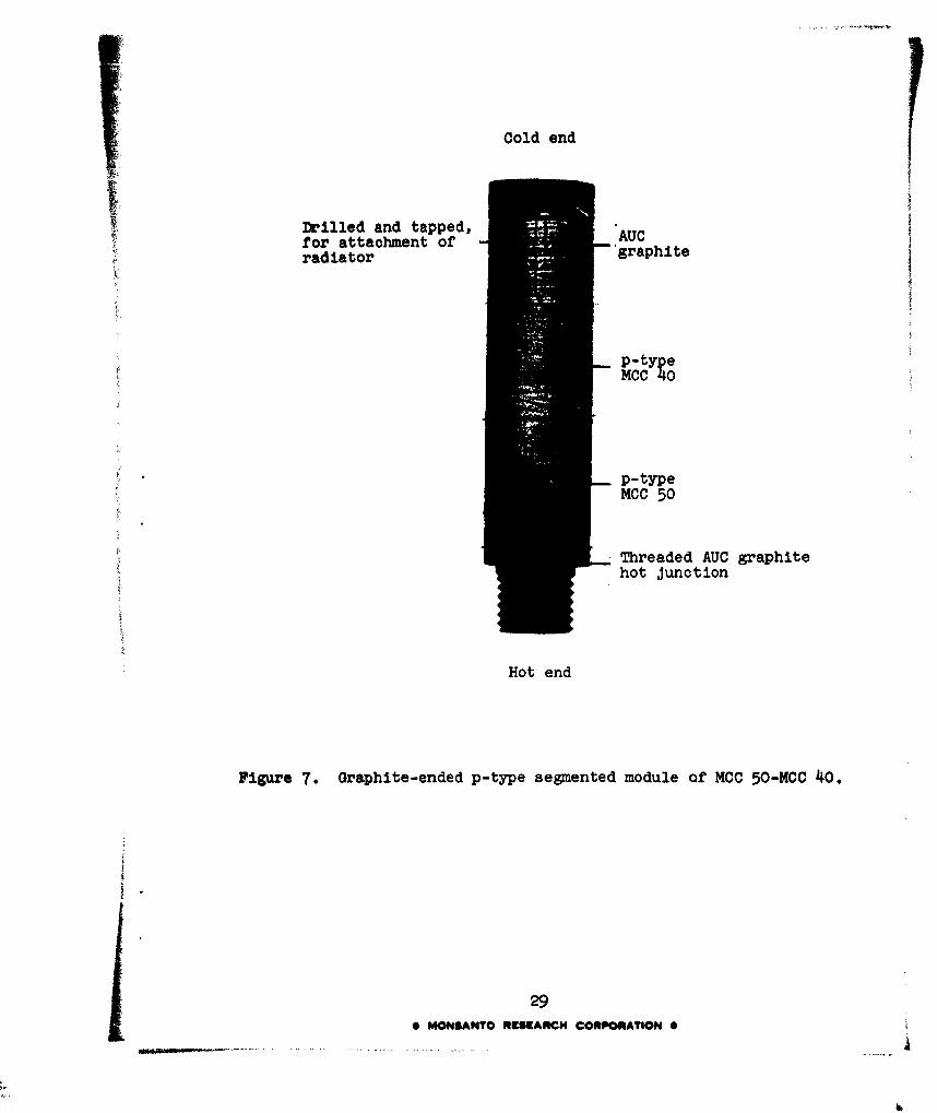
The temperature of the die assembly was raised to 20200 C in 5minutes while applying pressure to 4000 psi. These conditionswere maintained for 8-10 minutes. The assembly was then cooledto room temperature and one of the graphite ends was removed.The MCC 50-graphite interface was ground away, exposing a freshMCC 50 surface on one end of a 0.6 long MCC 50 element section.The diameter of the MCC 50 element was ground to 0.500" and usedas a plunger for the hot-pressing of the MCC 40 (p-type) elementto MCC 50. The p-type MCC 40 powder mix (5 g) was hot-pressed ina second boron nitride-lined graphite die between an AUC graphiteplunger on one end and the MCC 50-graphite plunger on the other.The temperature of the die was increased to 13500C over a 10-minute period while maintaining a rate of plunger travel of 0.01-0.02"/minute; When compaction of 0.2-0.3' had taken place, thetemperature was decreased to ambient while increasing the pressureto 2000 psi. Upon reaching ambient temperature, the die wasremoved from the hot press and the segmented module was removed.The MCC 50 and the MCC 40 sections of the p-type module, shown inFigure 7, were 0.5" long x 0.5" diameter.
An identical procedure,with the following exceptions, Wks used toproduce the graphite-ended segmented n-type module shown inFigure 8:
(1) Only 4 g of MCC 60 powder was used in place ofMCC 50 and a hot-pressing temperature of 21000Cwas used instead of 20200C. The length of theresultin§ MCC 60 module segment was 0.4" ratherthan 0.5
(2) In producing n-type MCC 40, 6.8 g of this powderwas used in place of 5 g of p-type MCC 40 and theresulting module segment was 0.6' long rather than0.51".
The light-colored material on the surface of the segmented p- andn-type modules of Figures 7 and 8 is MCC 40 that was extrudedaround the MCC 50 and MCC 60 and plungers during hot pressing.It is not necessary to remove this material since it will notharmfully affect the performance of the segmented modules. Itschief effect will be to increase the weight lost by vaporizationfrom segmented modules when a portion of the extruded MCC 40material is heated above 8500C in a vacuum.
The p- and n-type segmented modules, shown in Figure 7 and 8,are currently beinj tested as a p-n couple in a vacuum of 10-5 -10- 6 mm Hg at 1200 C (Th). The promising results of this tebtseries are presented under Sustained Testing, section II B5, ofthis report.
As discussed in the FourthQuarterly Report, the sizeable heat lbssesand fabrication costs inherent in the initial experimental modelgenerator design could be significantly reduced if sandwich-type
280 MONSANTO RESEARCH CORPORATION 0
Cold end
Drilled and tapped, AUCfor attachment of raht• 'graphiteradiator
p-type
MCC 40
p-typeMCC 50
Threaded AUC graphitehot Junction
Hot end
Figure 7. Graphite-ended p-type segmented module of MCC 50-MCC 40.
290 MONSANTO RESCARCH CORPORATION 0
Cold end
Drilled & tapped,for attachment -rahiAUCof radiator graphite
n-typeMCC 60
Threaded AUC graphitehot Junction
Hot end
Figure 8. Graphite-ended n-type segmented module of MCC 60-MCC 40.
30
0 MONSANTO R9SCARCH CORPORATION 9
ring-or doughnut-shaped modules of MCC 50 and other thermoelectricmaterials could be fabricated. Development of arc-plasma spraycoating techniques to produce such sandwich-type modules is anobjective of this phase of the project. A relati-e goal is to im-prove tk.-practicability of producing hot and cold junctions betweenthermoelectric modules via arc-plasma and flame spraying. Successin the latter would permit significant reductions in the weightof the advanced experimental model generator by eliminating fasten-ing pins or screws and by reducing the length of graphite nowrequired for attachment of junction and radiator materials at thehot and cold ends of modules.
Several sandwich-type MCC 50 modules were fabricated by arc-plasmamethods this quarter. One, a graphite-molybdenum-MCC 50-molybdenummodule, is shown in Figure 9. Its thermoelectric properties havenot yet been measured.
Other sandwich-type modules were evaluated in a vacuum of 12000C(Th) for S, and &T characteristics, as tabulated below. Satisfactoryelectrical contacts to the cold junction of these modules werenot accomplished, preventing measurement.of their resistance andpower output characteristics.
Thickness of Seebeck tT AcrossModule MCC 50 layer, Coefficient, Module,No. Description mils 4v/°OC Th,C 0C
82 Mo-MCC 50 1/16 308 1192 20084A C-Mo-MCC 50 1/16 136 1192 26486A C-Mo-MCC 50 1/8 185 1190 35089A C-Mo-MCC 50 1/16 266 1187 266
Each of the above modules withstood an ambient-1200OC-ambientthermal cycle in their evaluation. A thin (2-3 mil) coating ofmolybdenum was used to improve the bond between the graphite hotjunction material and MCC 50 for modules 84A, 86A and 89A.MCC 50 was sprayed directly on graphite to produce module 82. Thechief significanoeof the data from these 4 modules is thatsufficiently high Seebeck coefficients and &T's were obtained toindicate that useful thermoelectric modules can be made by thisapproach. It has definite possibilities as a technique for massproduction at lower costs and with more useful geometries formeeting generator design problems.
Techniques for attaching cold junction leads for measurement ofthe power output and resistance of complete modules like thatshown in Figure 9 are being investigated. In addition, new batchesof MCC 50 powder, with and without calcium oxide additive, arebeing prepared for use in further development of the arc-plasmamethod of fabricating sandwich-type modules.
31
0 MONSANTO RISEARCH CORPORATION 0
Figure 9. Sandwich-type module 86D made by arc-plasma spraycoating a thin coat of molybdenum on the graphitebase, followed by a 1/8" layer of MCC 50 and a finalcold Junction layer of molybdenum.
32
0 MONSANTO 111SMARCH CORPORATION 0
Figure 10. Experimental 2-leg module with arc-plasma spray coatedmolybdenum hot and cold junctions.
330 MONSANTO RESEARCH CORPORATION 0
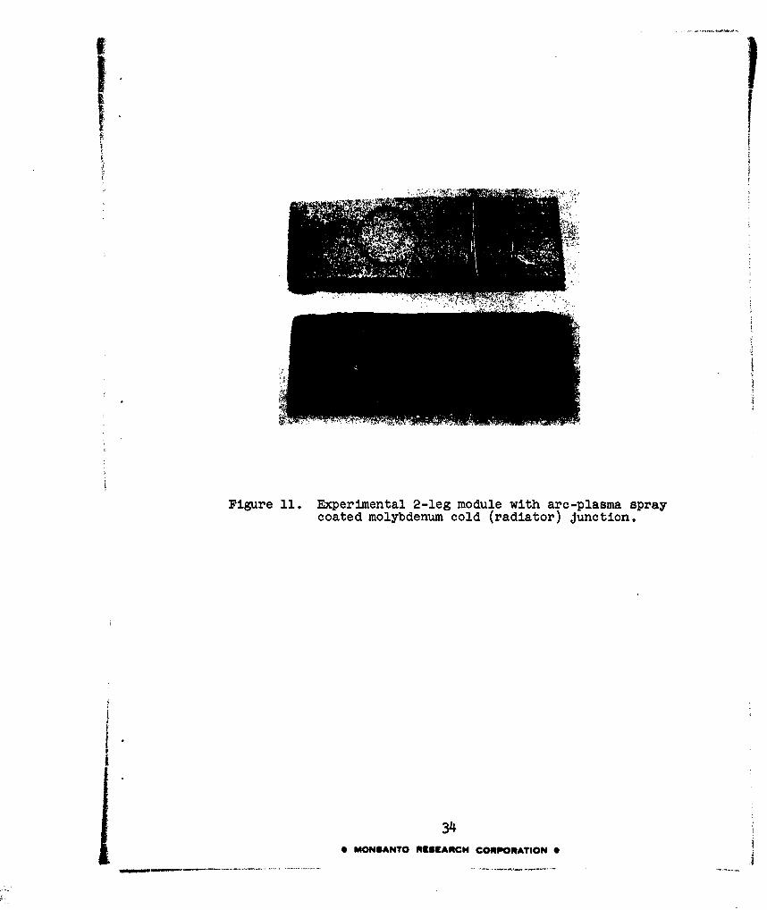
Figure 11. Experimental 2-leg module with arc-plasma spraycoated molybdenum cold (radiator) junction.
340 MONSANTO RESEARCH CORPORATION 0
An investigation was initiated this quarter of ways of utilizingarc-plasma and flame coating techniques to provide strong, thin,and lightweight hot and/or cold junctions between legs of p-ncouples. Such Junctions could be used in place of long and heavygraphite-molybdenum hot-junction shoes and graphite-copper radiatorsemployed on the 5-watt experimental generator. If this approachis successful, high power/weight ratios for the advancedexperimental model generator will be possible. Promising resultsin this effort were obtained, as shown in Figure 10. Here, twoshort graphite cylinders, simulating graphite-ended segmentedthermoelectric modules joined at their hot and cold ends byplasma-sprayed molybdenum, are shown. A second example ispresented in Figure 11 showing two short graphite cylinders joinedat one end (the radiator end) by plasma-sprayed molybdenum.This technique also offers high promise of adaptation to massproduction techniques and high power/weight ratios. However,more effort is needed to evaluate the mechanical strength, thermalshock resistance, and thermoelectric properties of junctions madethis way.
5. Sustained Testing
The most important milestone on this phase during the past quarterwas the initiation of sustained testing on the first p-n couplefabricated from the module shown in Figures 7 and 8. As shownin Figure 12, individual p- and n-type modules were screwed intoa combination graphite hot-junction heat source unit. The hot-junction unit is heated by a tungsten wire heater (not shown)wound around the vertical post below the large diameter-threadedportion of the unit. The two modules shown in Figure 12represent typical modules, not the p-n couples on which thedata in Table 6 was collected.
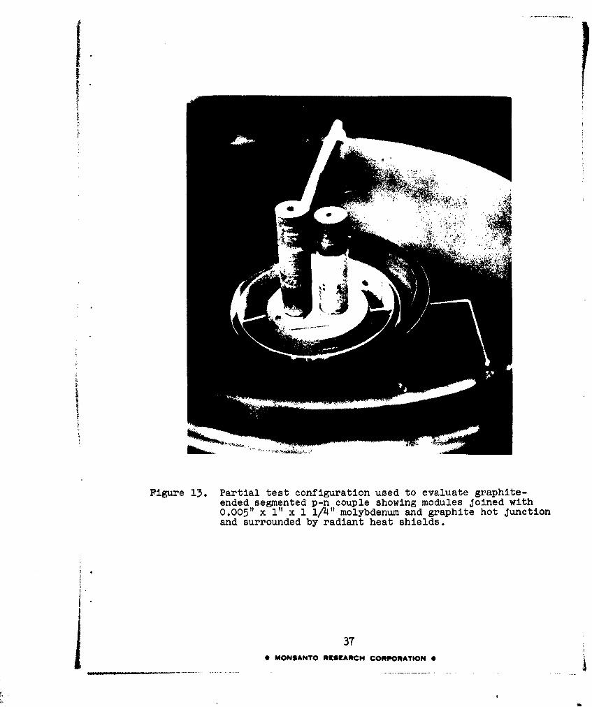
Figure 13 shows the p-n couples mounted on graphite within amultiwall radiation shield unit. The p-type MCC 50-MCd 40 legor module is the longest one shown. Coated-copper radiators,module power leads, and the top of the heat shield unit are notyet installed. An 0.005" x 1" x 1 1/4" molybdenum sheet (light-colored metal strip shown at the bottom or hot end of module)is used to lower the resistance of the hot junction end of thecouple. Alumina-insulated tungsten-rhenium thermocouples, whichmeasure the hot-end temperature, extend horizontally throughthe shields and outward from the graphite heat unit. Figure 14shows the completed test configuration for the sustained evaluationtests on the p-n segmented couple reported in Table 6.
The power output of the p-n couple shown in Figure 13 was 0.96watt with a &T of 7970C for a Th of 12140C. This is encouraginglyhigh. While it is not expected that a AT of 760-8000C can beobtained on the advanced generator, it is likely that &T's inthe neighborhood of 600-6500C (corresponding to radiator temperaturesof 550-600OC) can be achieved. With a 550-6000C AT and a Th of
35j 0 MONSANTO RESEARCH CORPORATION 0

®R .
Figure 12. Typical graphite hot-end Junction configuration forevaluating graphite-ended p-n couples.
36•MONSANTO RE[SEARCH CORPORATION
I|
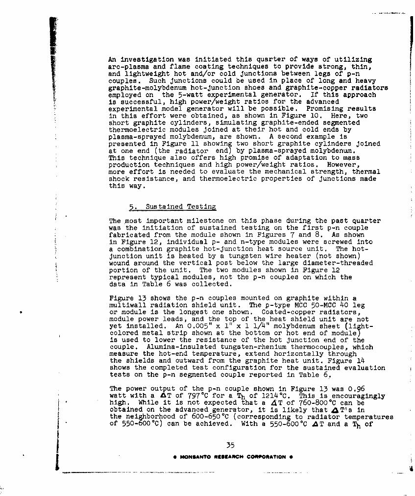
Figure 13. Partial test configuration used to evaluate graphite-ended segmented p-n couple showing modules Joined with0.005" x I" x 1 1/4" molybdenum and graphite hot Junctionand surrounded by radiant heat shields.
37* MONSANTO RESEAt•CH CORPORATION 0
I.l
Figure i4. Completed test configuration used to conduct sustainedevaluation tests on p-n couples.
38* MONSANTO RESEARCH CORPORATION 0
MO~~~t 0 n- 0 L~O - U L 4 L "
o t- ý0% UN t- m~ (h414) *n 4 C 4 n n n 4n
4) 0
c4 4 t tA - w0 0 w~ wU 00 -t\ ON 4t
0)L
1f) ( % 4 n n 4 'A LA A A A n4) ý4 0
00
to 93 91, 4 0 0 0 0 0 0 0 0
1ý 4 -PA U ' 0C J U 0
&4)
4)0 4)
F, 4) N oo ON 00 0 0
z 0 F0
Eý 0
U) HC\4 U' "N m' s ý 8 t
E4 ý LAc- 19 to- 0 0 0 to- 9 t .- I (U m-I 414
94
A)
4) -.
00 Hl H r, l
'0 MOSNO440f~tHCRORTO

vl200*C, it is anticipated that a power output of 0.7 watt percouple will be feasible for the advanced experimental generator.On this basis, the advanced generator should produce 250% morepower per module than was possible with the 5-watt model.
Since the test is continuing, sublimation losses cannot be determinedon each of the modules. This information will be obtained after250 hrs operation. The fact that power generating properties havenot decreased with time indicates that no serious sublimation ordiffusion damage has yet occurred. Tests on the p-n couple,
SFigure 13, are continuing. As further improvements in the thermo-electric properties of segmented couples are attained, couples ofsuch improved materials will be subjected to sustained evaluationtests.
Sublimation tests on individual single segment modules of MCC 60,MCC 40 (p-type), and MCC 40 (n-type) were also conducted. AnMCC 60 module, held at 12000C + 100C in a vacuum of 10-5 - 10-6
mm Hg, showed less than 1.9% viporization loss in 530 hrs. Ann-type MCC 40 module, run at 7000C + 100C in a vacuum of 10-5 -10-0 mm Hg, showed only a 0.12% los9 after 450 hrs. This loss wasso low that sublimation tests (,n p-type MCC 40 are being run at8500C.
40
0 MONSANTO RCSEARCH CORPORATION 0

III. CONCLUSIONS
Based on results obtained during the 2556-hr sustained performancetest, and the promising developments with n- and p-type thermo-electric materials needed to complement p-type MCC 50, the followingconclusions were reached:
1. The power generating properties of MCC 50-molybdenumcouples used in the experimental model ienerator arestable to 2556 hrs operat on at Th 1200 C (+25 0C-4 0 C)in a vacuum of 10-5 - i0- mm Hg.During this test thecouples sustained no visible damage from sublimation,diffusion at interfaces,or thermal cracking.
2. Power/weight ratios for the experimental model increasedfrom 2.5 watts/lb at the start of the test to 2.7 watts/lbafter 2556 hrs, an 8% gain in power output. This increaseprobably resulted from lowered junction resistances dueto vacuum welding at the cold ends of the MCC 50-molybdenum couples.
3. A more emissive coating, applied over the nickel oxidecoated-copper radiators of the experimental model generator,resulted in an increased AT of 400C.
4. Tests above 12000C should be run to determine the topfeasible operating temperature for this model.
5. Segmented p-n couples, based on MCC 50-MCC 40, MCC 60-MCC 40 modules when operated at a Th of 1200C, shouldproduce 0.7 watt/couple. An advanced experimentalgenerator equipped with such couples, a more emissivecoating and improved junctions should be capable ofa 10-20 watt/lb ratio.
41I MONSANTO RESEARCH CORPORATION e
I: IV. FUTURE PLANS
Effort during the next quarter will be devoted to the followingareas:
i. Sustained testing of the experimental model generatorat temperatures of 13000C and higher;
2. Efforts to improve p- and n-type MCC 40 materials andto fabricate and test improved p- and n-type segmentedcouples.
3. Attempts to further improve Junction forming techniques.
4. Development of a design for the advanced experimentalmodel generator.
5. Sustained evaluation tests on the most promisingthermoelectric materials in module and/ or coupleform.
42* MONSANTO RESEARCH CORPORATION 0