highest efficiency and ultra low emission – internal
TRANSCRIPT

Article citation info:
FRIEDL, H., FRAIDL, G., KAPUS, P. Highest efficiency and ultra low emission – internal combustion engine 4.0. Combustion Engines.
2020, 180(1), 8-16. https://doi.org/10.19206/CE-2020-102
8 Received 27 September 2019; Received in revised form 17 December 2019; Accepted 18 January 2020
Available online 30 March 2020 This is an open access article under the CC BY license (http://creativecommons.org/licenses/BY/4.0/)
Hubert FRIEDL CE-2020-102 Günter FRAIDL
Paul KAPUS
Highest efficiency and ultra low emission – internal combustion engine 4.0
In the future, the simultaneous reduction of pollutant and CO2 emissions will require significantly enhanced powertrain
functionalities that cannot only be adequately represented by the ICE (internal combustion engine) alone. Both automated transmissions
and especially powertrain electrification can help to meet efficiently those extended requirements. The extended functionalities are no
longer applied exclusively with the ICE itself ("Fully Flexible Internal Combustion Engine"), but distributed across the entire powertrain
("Fully Flexible Powertrain"). In addition, the powertrain will be fully networked with the vehicle environment and thus will utilize all
data that are useful for emission and consumption-optimized operation of the ICE.
Combustion engine and electrification often complement each other in a synergetic way. This makes it extremely sensible for the
combustion engine to evolve in future from a "single fighter" to a "team player". If one compares the requirements of such an ICE with
the definition of Industry 4.0, then there are extensive correspondences. Thus, it seems quite opportune to call such a fully networked
combustion engine designed to meet future needs as “Internal Combustion Engine 4.0 (ICE 4.0)”. This even more so, as such a name
can also be derived from the history: e.g. ICE 1.0 describes the combustion engines of the first mass-produced vehicles, ICE 2.0 the
combustion engines emission-optimized since the 1960s and ICE 3.0 the highly optimized "Fully Flexible Combustion Engine", which
currently offers a high torque and performance potential combined with low fuel consumption and pollutant emissions.
In addition to further improvements in fuel consumption, the "Combustion Engine 4.0" offers such a low level of pollutant emissions
that can best be described as "Zero Impact Emission". This means that such future ICE´s will no longer have a negative impact on the
imission situation in urban areas. With the e-fuels topic, the ICE also has the potential to become both CO2- and pollutant-neutral in the
medium and long term. This means that the ICE – also in passenger cars – will continue to be an essential and necessary cornerstone for
future powertrain portfolios for the next decades.
Key words: passenger car, gasoline, diesel, hybrid, powertrain
1. Introduction The combustion engine is currently undergoing the most
turbulent phase in its more than 100-year of history. From
the undeniable enabler of individual mobility, the ICE is
partly driven into a negative image as an air polluter and no
longer being a future oriented technology. Particularly in
Europe, the combination of exceeding imission limits in
major cities with the emissions issue of the Diesel engine,
has had a lasting impact on the image of the ICE. Potential
city access restrictions not only generate anxiety scenarios,
but also increasingly determine the buying behavior of the
customer and thus, not at least, question the future of the
Diesel engine in passenger cars. In the public discussion,
however, most often neither the resulting losses in people’s
assets and the contribution of non-automotive pollutant
emitters to the imission situation are considered.
Looking at the challenges of the ICE in a technically ra-
tional way against a global background, it is probably less the
issue of pollutants, but rather the sustainable reduction of
CO2 emissions, that presents the biggest challenge, Fig. 1.
Fig. 1. Global and regional challenges for the ICE
The fulfillment of the worldwide CO2 resp. fuel con-
sumption fleet limits is hampered both by a strongly in-
creasing portion of vehicles with high weight and driving
resistance (SUV boom) and thus unfavorable consumption
behavior compared to the passenger car as well as a still
restrained purchase behavior for XEV's.
In the US, low fuel prices give the customer a low eco-
nomic motivation to buy CO2-efficient vehicles. In addi-
tion, since the US legislation is traditionally more pollutant-
oriented than emissions-oriented, a more modest transition
to electromobility is expected.
In Europe, on the other hand, demanding CO2 reduc-
tions in conjunction with declining Diesel and SUV shares,
requires a relatively rapid expansion of electrification just
to meet the CO2 fleet targets. In addition, the shift towards
electrification is enhanced additionally by the ongoing
discussions about bans for the ICE.
In China, above all, the imission situation in mega cities
and the resulting registration restrictions and exemptions
for new energy vehicles (NEVs) are a major motivation for
electric drives.
Although the United States, especially California, have
been at the forefront of low pollutant emission legislation
for decades, in future both China with its extremely low
thresholds in the test cycle (China 6b) and demanding dura-
bility requirements, and especially Europe with a very chal-
lenging RDE legislation will become the pacemakers.
The short- and medium-term technology trends can be
estimated in a first approximation from the already apparent
or expected legislation, where strong regional differences
are to be expected. Long-term trends, on the other hand, are
mainly due to the CO2 reductions required to meet the cli-

Highest efficiency and ultra low emission – internal combustion engine 4.0
COMBUSTION ENGINES, 2020, 180(1) 9
mate goals. However, these must be seen as balance be-
tween the CO2 emissions of the transport sector ("Tank- to-
Wheel") and the provision of primary energy ("Well-to-
Tank"). Although the division into individual sectors allows
the definition of separate target values, there is the risk that
over the time course the overall optimum of CO2 reduction
will not always be achieved. For example, a reduction of
purely vehicle-related tank-to-wheel emissions by electric
vehicles only becomes effective in the total CO2 emissions,
if the well-to-tank emissions of the energy supply are re-
duced beforehand.
Of course, in addition to technical progress in develop-
ment, a wealth of legal and political influencing factors
determines the long-term development of technology. The
issues of registration and access restrictions ("Diesel-Ban",
"ICE-Stop") certainly play a decisive role, Fig. 2.
Fig. 2. Main factors influencing the long-term global technology distribu-
tion [1]
In addition to the reduction of pollutant emissions, ful-
filling the fleet CO2 limits is a key driver for electric vehi-
cles, whose emission contribution is currently rated "zero".
Thus, a transition from a tank-to-wheel to a well-to-wheel
approach with today's powerplant CO2 footprint would
significantly reduce the lever of the electric vehicles in fleet
CO2 and, above all, reduce the attractiveness of plug-in
hybrids (PHEV). Similarly, advances in battery technolo-
gies are also competing the need for PHEV as a long-haul
solution, even though the general fast-charging issue of
increasing inventory of BEVs with very high battery capac-
ity in long-haul operations is challenging.
The success of the fuel cell is much more determined by
the infrastructure than in the case of the battery-powered
vehicle. Here, in a global view, both the storage and the
distribution of hydrogen are still inhibitions. However,
vehicle refueling itself can be solved in a practical way by
the possible transfer of high energy contents within a brief
time.
With the ICE, on the other hand, the topics "Zero Im-
pact Emission" and "e-Fuels” as well as “e-Gas" also make
it possible to operate the ICE practically pollutant-free and
CO2-neutral, thus bringing it to a level with renewable
sources in terms of environmental impact in a then fair
competition again.
2. A new generation of ICE´s Basically, there are two options for meeting future CO2
fleet targets and emission limits:
• Electrification focus: The emphasis is placed on the
highest possible proportion of electrification (BEV +
PHEV), if necessary, a corresponding market penetration is
promoted with price support measures. In the case of con-
ventional drives, the focus is primarily only on the adapta-
tion to the legal boundaries, most of the CO2 fleet reduction
is represented by BEV and PHEV.
• Balanced approach: In addition to the "marketable"
growth of BEV + PHEV, the further reduction of CO2
emissions is the result of a significant advancement of ICE
based powertrains utilizing synergies with affordable elec-
trification measures.
However, looking at the current evolution of CO2 fleet
levels in Europe – the progression of CO2 reduction is well
above the target corridor for meeting the fleet targets for
2020 due to rising SUV and falling diesel emissions – all
technical options for CO2 reduction will have to be exploit-
ed. In conjunction with the also tightened RDE require-
ments, this requires a sustainable improvement or new
development of ICE based powertrains.
Since the issue of real world emissions will increasingly
come into the focus, it is becoming more sensible to in-
creasingly use the traffic and environmental information
available through the networking of the automobile to op-
timize fuel consumption and pollutant emission of the
powertrain. To use such a potential, it is necessary to inte-
grate electrical functionalities into the powertrain in addi-
tion to refined ICE attributes.
If one compares these requirements to future power-
trains with the definition of Industry 4.0, in Germany, then
surprising matches are found:
Definition Industry 4.0 [2] (in extracts, in the following
in italics):
• "Industrial production should be integrated with
modern information and communication technology". This
also applies also to automobile and optimized powertrain
management.
• "The technical basis for this are intelligent and digi-
tally networked systems. With their help, a largely self-
organized production is to be possible: people, machines,
equipment, logistics and products communicate and coop-
erate directly with each other in Industry 4.0”. This sen-
tence describes in an analogous manner also autonomous
driving functions and the networking of the automobile.
• "Networking should make it possible to optimize not
just a single production step but an entire value chain".
Also in the automobile, it will be possible in the future, to
optimize not only the driving itself, but the entire transport
process including energy-optimal route selection, maximiz-
ing the recuperation potentials and automation of assistance
functions such as automatic parking.
• "The network should also encompass all phases of
the product's lifecycle – from the idea of a product to de-
velopment, manufacturing, use and maintenance to recy-
cling." In the future, the evaluation of the automobile and
the various drives will also be increasingly carried out on
a "lifecycle" basis involving production, operation and
recycling.
Thus, it is perfectly opportune to call an ICE designed
comprehensively for future needs as “Internal Combustion
Highest efficiency and ultra low emission – internal combustion engine 4.0
10 COMBUSTION ENGINES, 2020, 180(1)
Engine 4.0 (ICE 4.0)”. But also from the history can be
derived such a name, Fig. 3.
“ICE 1.0” describes the combustion engines of the first
mass-produced vehicles. Affordability and reliability were
the defining parameters.
In California, the first emission limits for motor vehicles
were already set in the 1960s, which is certainly a decisive
milestone, e.g. defined as “ICE 2.0”.
Fig. 3. Generations of ICE based passenger car power- train systems
In the following decades, the limit values for pollutant
emissions and fleet consumption target values to be proven
on the chassis dynamometer were steadily tightened and
required significantly increased variability, the "Fully Flex-
ible Internal Combustion Engine – here described as “ICE
3.0”.
The future requirements regarding pollutant as well as
CO2 emissions, require significantly extended functionali-
ties of the powertrain, which no longer can be mapped
exclusively within the ICE ("Fully Flexible Combustion
Engine") but must be distributed to the entire drive train
("Fully Flexible Powertrain"). In addition, the drivetrain
will be networked with the vehicle environment, enabling
all data useful for emission-optimal powertrain operation to
be utilized, and will increasingly be powered by CO2-
neutral fuels from renewable sources – “ICE 4.0”.
Zero Impact Emission In addition to the currently negatively biased image of
the ICE, the complex discussions regarding access re-
strictions for emission-critical zones are causing uncertainty
among the buyer. Especially the lack of clearly defined
future framework conditions becomes an existential threat
to the Diesel engine in passenger cars already short term.
In the medium and long term, a general sales stop of
ICE is increasingly being discussed, without considering
the untapped potential of future ICE-based powertrain sys-
tems. To remain accepted, at least in the European public
opinion, it is generally necessary for the ICE to lower its
pollutant emissions to a level that is no longer relevant for
the environment. With EU6dtemp incl. RDE, a decisive
step has already been made in this direction. It can be as-
sumed that such vehicles will certainly fall below the imis-
sion limit values in today's imission-critical zones.
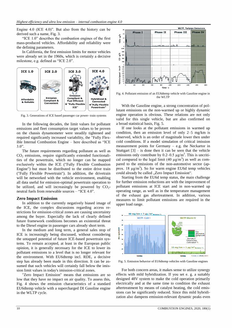
"Zero Impact Emission" means that emissions are so
low that they have no impact on air quality. To assess this,
Fig. 4 shows the emission characteristics of a standard
EU6dtemp vehicle with a supercharged DI Gasoline engine
in the WLTP cycle.
Fig. 4. Pollutant emission of an EU6dtemp vehicle with Gasoline engine in the WLTP
With the Gasoline engine, a strong concentration of pol-
lutant emissions on the non-warmed up or highly dynamic
engine operation is obvious. These relations are not only
valid for this single vehicle, but are also confirmed on
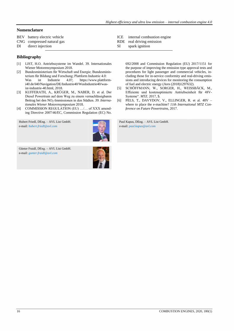
a broad statistical basis, Fig. 5.
If one looks at the pollutant emissions in warmed up
condition, then an emission level of only 2–5 mg/km is
observed, which is an order of magnitude lower then under
cold conditions. If a model simulation of critical imission
measurement points for Germany – e.g. the Neckartor in
Stuttgart [3] – is done then it can be seen that the vehicle
emissions only contribute by 0.2–0.5 µg/m3. This is uncriti-
cal compared to the legal limit (40 µg/m3) as well as com-
pared to the emissions of the non-automotive sector (ap-
prox. 18 µg/m3). So for warm engine EU6d temp vehicles
could already be called „Zero Impact Emission“.
Starting from the EU6d temp status, the main challenge
for further emission reductions are with the improvement of
pollutant emissions at ICE start and in non-warmed up
operating range, as well as in the temperature management
of the exhaust gas aftertreatment. In addition, various
measures to limit pollutant emissions are required in the
upper load range.
Fig. 5. Emission behavior of EU6dtemp vehicles with Gasoline engines
For both concern areas, it makes sense to utilize synergy
effects with mild hybridization. If you set e. g. a suitably
designed 48V system to make the cold operation primarily
electrically and at the same time to condition the exhaust
aftertreatment by means of catalyst heating, the cold emis-
sions can be significantly reduced. Since this mild hybridi-
zation also dampens emission-relevant dynamic peaks even

Highest efficiency and ultra low emission – internal combustion engine 4.0
COMBUSTION ENGINES, 2020, 180(1) 11
when warm (limitation of the ICE dynamics), it is possible
to achieve an emission level that justifies talking about
"Zero Impact Emission".
3. Electrification of the ICE In the future, the simultaneous reduction of both pollu-
tant and CO2 emissions will require significantly enhanced
functionalities of the powertrain, which can only be insuffi-
ciently represented by the ICE alone. Both automated
transmissions and electrification can help to efficiently
cover the extended functionalities. These functionalities are
no longer exclusively applied within the ICE itself ("Fully
Flexible Internal Combustion Engine"), but distributed
across the entire powertrain ("Fully Flexible Powertrain"),
Fig. 6.
Clever balancing of the complementary properties of
electrification and ICE results in a synergetic potential for
improvement in terms of reducing both pollutant and CO2
emissions. Thus, in future the ICE will change "from a lone
fighter to a team player".
As a result, especially with a high degree of electrifica-
tion, a simplification of the ICE will be also possible. If e.g.
the lowest load range of the ICE is replaced by purely elec-
tric driving or load shift by charging the battery, the layout
of the ICE can focus on the area of best specific fuel con-
sumption respectively low specific pollutant emissions
(with Gasoline engine e.g. layout of the turbocharger for
higher mass flow, possibly omission of variable valve lift,
modified layout of variable compression, etc.).
Fig. 6. From "Fully Flexible Combustion Engine" to "Fully Flexible
Powertrain" [1]
Already a sufficiently graded automated transmission
with a large spread helps to operate the ICE in most of the
driving situations in the respectively optimum map area –
usually best specific fuel consumption ("Sweet Spot Fol-
lower" – yellow area in Fig. 7). With appropriate hybridiza-
tion, even at low power demand the load point can be shift-
ed towards a high-efficiency range either by electrical recu-
peration and charging of the battery or, in the case of suffi-
cient battery charge, driven purely electrically (lower green
area in Fig. 7).
In the upper load range, of course, the electrical torque
can be used to increase the total torque (dashed green line).
Regarding emission and fuel consumption reduction, how-
ever, it is more sensible to reduce the torque and dynamic
demand of the ICE by means of the additional electrical
torque at least partially, especially with low engine speeds
(upper green area in Fig. 7). This not only allows avoidance
of operating ranges with unfavorable performance of the
ICE, but also additional synergy effects e.g. a modified
design of the turbocharger better matched to the higher flow
range (expansion of the stoichiometric operating range). In
view of the expected changes in RDE legislation [4], such
a "dynamic limitation" of the ICE also gains additional
importance for a robust RDE calibration. However, the
electrical torque is only temporary, according to the electric
energy available, which must be considered in the system
design accordingly.
Fig. 7. Interaction of ICE, Automated Transmission and Mild Hybridiza-
tion (48V)
Depending on the respective ICE, transmission and
electrification strategy, different arrangements of the elec-
tric motor prove to be the respectively most favorable vari-
ant, Fig. 8. Both modular and dedicated solutions are used
[5, 6].
Fig. 8. Electrification of ICE-based powertrain systems
4. Development of the Gasoline Engine
4.1. Challenges
Due to its in stoichiometric operation highly efficient
exhaust aftertreatment, the Gasoline engine has so far been
much less in the center of public emission discussions than
the Diesel engine. However, the new RDE legislation, es-
pecially the tightening of Package 3 and 4, represents
a huge challenge. Thus, e.g. the dynamic limitation intro-
duced to restrict aggressive driving allows, to a certain

Highest efficiency and ultra low emission – internal combustion engine 4.0
12 COMBUSTION ENGINES, 2020, 180(1)
extent, even extreme driving maneuvers such as full load
drive-off with cold engine. Consequently, reducing the
dynamics of the cold drive-off becomes a crucial criterion
for safely meeting future RDE requirements.
The strongest temperature and dynamic influence is ob-
tained in the gasoline engine for the number of particles,
Fig. 9.
Fig. 9. Influence of start temperature and driving style on the engine-out
particulate emissions in the RDE city section – TGDI engines
Since particulate filters for Gasoline engines, at least in
the new or freshly regenerated state have significantly low-
er filtration efficiencies than Diesel particulate filters,
a reduction of the particle engine out emissions is still re-
quired despite the broad introduction of the particulate filter
also with Gasoline engine. By detail optimization both the
temperature and the dynamic sensitivity of PN generation
could be significantly improved from an EU6c status, Fig.
10 left, towards an EU6d status, Fig. 9 right.
Compared to the Diesel engine, the Gasoline engine has
a much higher sensitivity to higher exhaust gas back pres-
sure, which gains in importance through the future require-
ment for stoichiometric operation in the entire map. Thus, the
trade-off between filtration efficiency and exhaust back pres-
sure of the GPF becomes a defining parameter for the Gaso-
line engine. Fig. 10 shows an overview of different filter
types with respective filter soot loadings of 0, 1 and 3 g/l.
Fig. 10. Trade-off between filter efficiency and exhaust back pressure with
different soot loadings
While in the past, high filtration efficiencies were al-
most inevitably associated with high backpressure (red and
yellow areas in Fig. 10), current developments are already
leading to much more favorable relations – green area in
Fig. 10 – although partially with compromises on filter size.
For gas-powered SI-engines this filter problem is eliminat-
ed, as from combustion side more or less no particle emis-
sion is generated thus increasing the attractiveness of Gas
engines additionally.
Finally, the elimination of scavenging strategies neces-
sary to safely comply with RDE-NOx, requires appropriate
compensation in torque and low-speed response, which in
turn argues for a "cooperation" between ICE and powertrain
electrification.
In general, some measures for the robust RDE fulfill-
ment are in trade-off with the CO2 emission, the central
future development focus of the Gasoline engine. This
increases the motivation to use low-cost electrification to
reduce CO2 emissions and to improve existing trade-offs,
for example with a different layout of the turbomachinery.
Since such mild hybridizations can also improve the ro-
bustness of emissions reduction in real world operation at
the same time, such systems will form a broad basis for
future ICE based powertrains.
4.2. Technology approaches Gasoline engine
The current technical mainstream of Gasoline engines –
extended expansion by Miller/Atkinson cycle concepts –
will continue in the foreseeable future, but will be further
optimized by improved charging systems. In addition to this
mainstream technology, however, a certain amount of tech-
nology diversification will remain. Variable Compression
Ratio VCR, Spark Initiated HCCI, advanced ignition and
Ultra High Pressure Injection UHP are additional focus
points, Fig.11.
Fig. 11. Technology roadmap Gasoline engine
Once knock can be limited or eliminated isolation of the
combustion chamber (“adiabatic engine“) can shift energy
from the low temperature to the high temperature level. In
combined processes these additional energy amounts can be
used. Peak efficiency levels of 45% up to 50% can be ex-
pected in the future.
Future emission requirements such as lowest particulate
emissions or stoichiometric operation in the complete en-
gine map require advanced emission concepts beyond the
three way catalyst and the particle filter.
By using an electrically heated catalyst with extended
preheating/post heating functionality (“conversion man-
agement”) as well as by hybridization and connectivity
further significant emission reduction up to “Zero Impact
Emission” level is possible even for not fully warmed up
engines.
Synergy effects with hybridization allow an even more
fuel consumption-oriented design of the IC, especially of
the charging and combustion processes. Since in future, the
ICE must increasingly cover various levels of electrifica-

Highest efficiency and ultra low emission – internal combustion engine 4.0
COMBUSTION ENGINES, 2020, 180(1) 13
tion, an expanded modularization will gain an increasing
importance even within the ICE. While in the past, different
torque and power levels of the ICE were usually covered
with different geometric displacements, the topic of charg-
ing enables a power and torque spread without changing the
engine geometric displacement. Miller and Atkinson cycle
allow a separation of geometric and effective compression
ratio. Thus, a widely spread power graduation can be dis-
played at the same geometric displacement within one en-
gine family. The performance differentiation is primarily
based on the extent of "Millerization", the boost pressure,
the valve lift curves and the geometric compression ratio,
Fig. 12.
Fig. 12. Modular Gasoline engine concept with different electrification
levels
While high torque at low engine speeds is a prerequisite
for a fuel economy oriented powertrain layout, it usually
results in some compromises with the ICE layout. Thus, an
electrical torque assistance at low speeds allows a much
more focused orientation of the ICE to the main operating
range, Fig. 12 center. In most cases, the charging unit can
also be better adapted and if necessary also simplified and
the geometric compression ratio can be raised further.
Recovery of exhaust gas energy, for example by means
of electrified turbochargers (e-turbo) in combination with
the electrified powertrain, is a sensible addition to a further
increase in efficiency.
Niche applications with extremely high specific power
are made possible by using additional electrical charging.
With the increased electrical power of high-voltage full
hybrids, this alignment can be taken a step further, Fig.12
lower part. Since considerably higher electrical energies are
converted here, an intelligent, preferably predictive energy
management is required to assure reproducibility of the
acceleration behavior with limited battery capacity.
In contrast to the low speed range, the direct influence
of electrification in the rated power range is limited by
economically justifiable battery sizes (exception: Plug In
Hybrid). However, synergy effects – such as e.g. reduced
exhaust back pressure can be used by modified layout of
the gas exchange process respectively the turbocharger.
Nevertheless, future legal requirements such as stoichi-
ometric operation in the entire map remain challenging and
require either a compromise with CO2 measures or addi-
tional expenses. A variety of measures is – either individu-
ally or in combination – is used to reduce the exhaust gas
temperature so far that an enrichment for component pro-
tection can be avoided. Fig. 13 shows an overview of the
stoichiometric power potential of the individual technolo-
gies and the cross-influence on the minimum specific fuel
consumption.
Active exhaust gas cooling in the form of an integrated
exhaust manifold is increasingly becoming the basic tech-
nology of turbocharged Gasoline engines, but is limited
towards higher performance by the high heat input into the
cooling system. Miller timing (early inlet valve closure)
provides a broad basis for the implementation of high geo-
metric compression ratio and extended expansion and is
primarily used to reduce fuel consumption. Improved gas
exchange (Variable Turbine Geometry, "Series Compressor
Turbocharger" with intercooler) enables lower charge tem-
peratures and better charging efficiencies. Cooled exhaust
gas recirculation improves both the stoichiometric power
range and the minimum fuel consumption, but at the same
time increases the heat input into the cooling system. Vari-
able geometric compression ratio, especially in conjunction
with variable intake valve lift proves to be very effective
both in view of stoichiometric power and fuel consumption.
And finally, water injection – albeit with respective water
consumption – enables stoichiometric operation up to more
than 170 kW/l.
Fig. 13. Measures to increase the stoichiometric power range, RON 95

Highest efficiency and ultra low emission – internal combustion engine 4.0
14 COMBUSTION ENGINES, 2020, 180(1)
With increasing electrification, the focus of fuel con-
sumption is shifting from the low load range (for example
2000 rpm, 2.0 bar BMEP) towards higher engine loads to
the area of minimum specific fuel consumption. Thus, the
ratio of maximum efficiency to maximum specific power
becomes a decisive engine parameter, Fig. 14.
Fig. 14. Trade-off between max. efficiency and max. specific performance
Looking at the state of the art, Miller/Atkinson concepts
represent the most attractive low-consumption solutions.
With advanced charging systems and refined combustion
processes, a significant shift of this trade-off is expected in
the future, especially towards higher specific performance.
However, the requirements of stoichiometric full load oper-
ation will result in increased differentiation in these specific
performance levels. Although the concept engines (hollow
circles in Fig. 14) are already designed for stoichiometric
operation, stoichiometric full load is only applied to a few
series engines yet.
While overall efficiencies of up to 45% appear feasible
in the medium term for current developments, in the re-
search stage total efficiencies of more than 50% are con-
ceivable in the long term with complex processes. This
significantly extends the trade-off between maximum effi-
ciency and specific performance compared to the current
state of the art, Fig. 15.
Fig. 15. Trade-off between maximum efficiency and specific power of Gasoline engines
The benchmark here are Formula 1 engines, which – not
restricted by the limitations of series solutions and emission
compliance – already achieve such efficiencies. If, on the
other hand, one considers the boundary conditions of series
engines, an increase in the compression ratio is a central
topic for improving efficiency. A technically comparatively
simple solution is a monovalent CNG engine that converts
CNG's high anti-knock properties into additional efficiency
improvements in addition to its chemical CO2 advantage.
This is a technically ideal solution that in future will also
offer the possibility of using CO2-neutral gas produced
from renewable energies distributed in basically existing
networks that are easy to expand. Unfortunately, this ap-
proach so far had poor customer and political resonance and
thus in the past a restrained market acceptance. Hopefully
CNG finally will achieve the importance it deserves.
Another much discussed approach are lean concepts.
Since there are additional question marks for any form of
lean operation due to the current NOx emission discussions,
avoiding knocking combustion as an enabler for higher
compression may be a more promising route. However,
many of the conventional knocking methods are based on
charge cooling and thus from the process point of view,
they are a thermodynamic loss which also increases the
required cooling capacity. A practically "knock-free" Gaso-
line engine would enable a significant paradigm shift: an
increasingly adiabatic engine which transfers the wall heat
losses into exhaust gas enthalpy and allows the respective
utilization of this exhaust gas energy in a subsequent ex-
pansion process, Fig. 16 upper part.
Fig. 16. Technology approaches for further increased efficiency of the
Gasoline engine
Such a knock-reduced Gasoline engine would be also an
ideal basis for homogeneous auto-ignition, Fig. 16 lower
part. As early as 2004, AVL had demonstrated that spark
ignition-triggered "auto-ignition" (AVL JCAI-Jet Con-
trolled Auto Ignition) dramatically improves the robustness
and stability of conventional HCCI technologies. However,
since NOx emissions require lean exhaust aftertreatment,
such a system has not been prioritized furthermore but has
been switched to more emission-stable stoichiometric ap-
proaches. Another possibility for improving the knocking
behavior, and also the charge dilution tolerance, is, for
example, a pre-chamber spark plug, Fig. 17.
By appropriate alignment of the ignition jets, the com-
bustion can be specifically accelerated in the direction of
knock-critical areas and thus the knocking behavior can be

Highest efficiency and ultra low emission – internal combustion engine 4.0
COMBUSTION ENGINES, 2020, 180(1) 15
improved. An advancement of 50% mass fraction burnt
point of up to 8°CA was achieved.
Fig. 17. Pre-chamber ignition
The most efficient measure to prevent pre-ignition and
knocking, however, is the introduction of the fuel only at
the end of the compression immediately before ignition,
Fig. 18. The local residence time of the fuel in knock-
critical areas is too low to trigger pre-ignition or knock =>
practically "knock-free" Gasoline engine.
Fig. 18. “Knock-Free Engine”; Ultra High Injection Pressure
However, the very late introduction and the necessary
preparation and distribution of the fuel requires extremely
high injection pressures. With injection pressures > 800 bar
and an adequate system design, a sufficient mixture for-
mation quality and homogenization can be achieved even at
very late injection.
Fig. 19 shows the effect of such a knock-reduced com-
bustion process in the engine map. With increasing the
geometrical compression ratio with a standard Miller com-
bustion system, e.g. from 12 to 14, shifts the area of best
BSFC (“sweet spot”) towards lower engine loads, however,
compromises the high load behavior quite significantly
especially at low speeds, Fig.19 center.
Fig. 19. Impact of a knock reduced combustion process in the engine map,
no EGR
With an "ICE only" powertrain, the reduced full load
torque would require a shorter drive ratio for comparable
performance and thus equalize the fuel consumption bene-
fits in the lower map range again. With a Hybrid, low-speed
assistance can be provided by an electrified powertrain.
Nevertheless, disadvantages would remain in the higher
load range.
A knock-reduced combustion method can fully exploit
the advantages of an increased compression in the lower
load range, but avoids the disadvantages in the higher load
range and at full load, Fig.19 right hand. Thus, such knock-
reduced combustion processes represent the next step in
Miller concepts.
Conclusions Regarding the improvement of real world emissions, the
transition to RDE proves to be much more effective than
lowering the certification values on the chassis dynamome-
ter – by fulfilling the current RDE legislation, in real driv-
ing conditions, the RDE-induced widespread introduction
of the particulate filter on the Gasoline engine and the sig-
nificantly tightened specifications for cold and high load
emissions result in essential pollutant reductions. It can be
assumed that such vehicles will certainly fall below the
imission limits even in today's imission-critical zones.
Since the extended boundary conditions of RDE legisla-
tion are no longer limited to statistically relevant driving
conditions only, but can cover virtually all possible modes
of operation, the short-term fulfillment of these require-
ments is an incredible challenge for the automotive indus-
try.
The uncertainty of the future markets' reaction calls for
the development of modular structures of both with ICE´s,
transmissions and electrification components.
In the long term, new potentials of the ICE can be seen
with regard to both pollutant and CO2 emissions. In particu-
lar, synergy effects with electrification and the networking
of powertrain control with all vehicle-relevant traffic and
environmental information – "Internal Combustion Engine
4.0" – enables both further fuel consumption improvements
and an emission behavior that can be described as "Zero
Impact Emission". This means that future combustion en-
gines will not have a negative impact on the pollutant imis-
sion situation. With the e-fuels theme, the combustion en-
gine also has the potential in the medium and long term to
become both CO2-neutral and pollutant-neutral.
Highest efficiency and ultra low emission – internal combustion engine 4.0
16 COMBUSTION ENGINES, 2020, 180(1)
Nomenclature
BEV battery electric vehicle
CNG compressed natural gas
DI direct injection
ICE internal combustion engine
RDE real driving emission
SI spark ignition
Bibliography
[1] LIST, H.O. Antriebssysteme im Wandel. 39. Internationales
Wiener Motorensymposium 2018.
[2] Bundesministerium für Wirtschaft und Energie; Bundesminis-
terium für Bildung und Forschung; Plattform Industrie 4.0:
Was ist Industrie 4.0?, https://www.plattform-
i40.de/I40/Navigation/DE/Industrie40/WasIndustrie40/was-
ist-industrie-40.html, 2018.
[3] KUFFERATH, A., KRÜGER, M., NABER, D. et al. Der
Diesel Powertrain auf dem Weg zu einem vernachlässigbaren
Beitrag bei den NO2-Immissionen in den Städten. 39. Interna-
tionales Wiener Motorensymposium 2018.
[4] COMMISSION REGULATION (EU) …/… of XXX amend-
ing Directive 2007/46/EC, Commission Regulation (EC) No.
692/2008 and Commission Regulation (EU) 2017/1151 for
the purpose of improving the emission type approval tests and
procedures for light passenger and commercial vehicles, in-
cluding those for in-service conformity and real-driving emis-
sions and introducing devices for monitoring the consumption
of fuel and electric energy (Ares (2018)1297632).
[5] SCHÖFFMANN, W., SORGER, H., WEISSBÄCK, M.,
Effiziente und kostenoptimierte Antriebseinheit für 48V-
Systeme“. MTZ. 2017, 5.
[6] PELS, T., DAVYDOV, V., ELLINGER, R. et al. 48V –
where to place the e-machine? 11th International MTZ Con-
ference on Future Powertrains, 2017.
Hubert Friedl, DEng. – AVL List GmbH.
e-mail: [email protected]
Günter Fraidl, DEng. – AVL List GmbH.
e-mail: [email protected]
Paul Kapus, DEng. – AVL List GmbH.
e-mail: [email protected]