hitachi virtual storage platform g200 hardware reference … · hitachi reserves the right to make...
TRANSCRIPT

Hitachi Virtual Storage Platform G200Hardware Reference Guide
MK-94HM8020-07
October 2016
© 2015, 2016 Hitachi, Ltd. All rights reserved.
No part of this publication may be reproduced or transmitted in any form or by any means, electronicor mechanical, including copying and recording, or stored in a database or retrieval system forcommercial purposes without the express written permission of Hitachi, Ltd., or Hitachi Data SystemsCorporation (collectively “Hitachi”). Licensee may make copies of the Materials provided that any suchcopy is: (i) created as an essential step in utilization of the Software as licensed and is used in noother manner; or (ii) used for archival purposes. Licensee may not make any other copies of theMaterials. “Materials” mean text, data, photographs, graphics, audio, video and documents.
Hitachi reserves the right to make changes to this Material at any time without notice and assumesno responsibility for its use. The Materials contain the most current information available at the timeof publication.
Some of the features described in the Materials might not be currently available. Refer to the mostrecent product announcement for information about feature and product availability, or contactHitachi Data Systems Corporation at https://support.hds.com/en_us/contact-us.html.
Notice: Hitachi products and services can be ordered only under the terms and conditions of theapplicable Hitachi agreements. The use of Hitachi products is governed by the terms of youragreements with Hitachi Data Systems Corporation.
By using this software, you agree that you are responsible for:1. Acquiring the relevant consents as may be required under local privacy laws or otherwise from
authorized employees and other individuals to access relevant data; and2. Verifying that data continues to be held, retrieved, deleted, or otherwise processed in
accordance with relevant laws.
Notice on Export Controls. The technical data and technology inherent in this Document may besubject to U.S. export control laws, including the U.S. Export Administration Act and its associatedregulations, and may be subject to export or import regulations in other countries. Reader agrees tocomply strictly with all such regulations and acknowledges that Reader has the responsibility to obtainlicenses to export, re-export, or import the Document and any Compliant Products.
Hitachi is a registered trademark of Hitachi, Ltd., in the United States and other countries.
AIX, AS/400e, DB2, Domino, DS6000, DS8000, Enterprise Storage Server, eServer, FICON,FlashCopy, IBM, Lotus, MVS, OS/390, PowerPC, RS/6000, S/390, System z9, System z10, Tivoli,z/OS, z9, z10, z13, z/VM, and z/VSE are registered trademarks or trademarks of InternationalBusiness Machines Corporation.
Active Directory, ActiveX, Bing, Excel, Hyper-V, Internet Explorer, the Internet Explorer logo,Microsoft, the Microsoft Corporate Logo, MS-DOS, Outlook, PowerPoint, SharePoint, Silverlight,SmartScreen, SQL Server, Visual Basic, Visual C++, Visual Studio, Windows, the Windows logo,Windows Azure, Windows PowerShell, Windows Server, the Windows start button, and Windows Vistaare registered trademarks or trademarks of Microsoft Corporation. Microsoft product screen shots arereprinted with permission from Microsoft Corporation.
iPad is a trademark of Apple Inc., registered in the U.S. and other countries.
All other trademarks, service marks, and company names in this document or website are propertiesof their respective owners.
2Hitachi Virtual Storage Platform G200 Hardware Reference Guide
Contents
Preface................................................................................................. 7Safety and environmental notices..............................................................................8Equipment with Network Equipment-Building System specifications............................. 9General safety guidelines........................................................................................ 10
Handling of heavy parts.................................................................................... 10Preventing electric shock...................................................................................10Avoiding rotating or moving parts...................................................................... 11Preventing machine damage..............................................................................11Working when the storage system is turned on...................................................11Precautions when using the storage system........................................................11Procedures in an emergency..............................................................................12
For electric shock........................................................................................ 12For fire....................................................................................................... 12
Intended audience................................................................................................. 13Product version......................................................................................................13Release notes........................................................................................................ 13Changes in this revision..........................................................................................13Document conventions........................................................................................... 13Conventions for storage capacity values...................................................................14Accessing product documentation........................................................................... 15Getting help...........................................................................................................15Comments.............................................................................................................16
1 Product overview............................................................................ 17Block configuration.................................................................................................18Hitachi Virtual Storage Platform G200 model............................................................ 18Features................................................................................................................19Scalability.............................................................................................................. 20
Examples of supported Hitachi Virtual Storage Platform G200 configurations.........20Maximum number of mounted drive trays...........................................................21
3Hitachi Virtual Storage Platform G200 Hardware Reference Guide

2 Hardware description.......................................................................25Storage system controllers......................................................................................26
CBSS controller.................................................................................................26CBSS with front panel bezel......................................................................... 26CBSS front panel without bezel.....................................................................27CBSS rear panel.......................................................................................... 28
CBSL controller.................................................................................................29CBSL with front panel bezel......................................................................... 29CBSL front panel without bezel.....................................................................30CBSL rear panel.......................................................................................... 31
Controller interfaces............................................................................................... 33Front end module descriptions...........................................................................33
10 Gbps iSCSI board LEDs and connectors (optical).......................................3310 Gbps iSCSI board LEDs and connectors (copper)...................................... 348/16/32 Gbps Fibre Channel (4-port) board LEDs and connectors................... 3516 Gbps Fibre Channel (2-port) board LEDs and connectors........................... 36
LAN blade LEDs and connectors.........................................................................38Back end module LEDs and connectors.............................................................. 38CBSS/CBSL AC power supply unit LEDs and connectors....................................... 39CBSSD/CBSLD DC power supply unit LEDs and connectors.................................. 39
Storage system drive trays......................................................................................40Small form factor (SFF) drive tray...................................................................... 40
SFF with front panel bezel............................................................................40SFF front panel without bezel.......................................................................41SFF rear panel............................................................................................ 42
Large form factor (LFF) drive tray...................................................................... 42LFF with front panel bezel............................................................................42LFF front panel without bezel....................................................................... 43LFF rear panel.............................................................................................44
Flash module drive (FMD) tray...........................................................................45FMD with front panel bezel.......................................................................... 45FMD front panel without bezel......................................................................45FMD rear panel........................................................................................... 47
Dense intermix drive tray.................................................................................. 48Dense intermix drive tray with front panel bezel............................................ 48Dense intermix drive tray display LEDs..........................................................49Dense intermix drive tray rear panel............................................................. 49
SFF and LFF AC power supply unit LEDs and connectors......................................50SFF and LFF DC power supply unit LEDs and connectors..................................... 51
Hitachi Virtual Storage Platform SVP server.............................................................. 51Service processor description.............................................................................52SVP front panel................................................................................................ 53SVP rear panel..................................................................................................53
3 System option modes...................................................................... 55System Option Modes.............................................................................................56
4 Maintaining the storage system........................................................87Storing the storage system..................................................................................... 88
4Hitachi Virtual Storage Platform G200 Hardware Reference Guide

Using flash module drives....................................................................................... 88Powering off the storage system............................................................................. 89Removing cables.................................................................................................... 89
5 User administration for maintenance utility........................................91Required roles for operating Maintenance Utility....................................................... 92Setting up user accounts........................................................................................ 93Disabling user accounts.......................................................................................... 95Removing user accounts.........................................................................................99Backing up user accounts......................................................................................102Restoring user account information........................................................................102
A Storage system specifications.........................................................105Model lists........................................................................................................... 106
Hitachi Virtual Storage Platform G200 controller model list................................. 106Drive tray model lists...................................................................................... 112Other model list..............................................................................................116
Replacement parts................................................................................................118Battery unit.................................................................................................... 118
Hitachi Virtual Storage Platform G200 mechanical specifications (AC power supplymodel)................................................................................................................ 119Hitachi Virtual Storage Platform G200 mechanical specifications (DC power supplymodel)................................................................................................................ 123Electrical specifications......................................................................................... 127VSP G200 electrical specifications (DC power supply)..............................................128Environmental specifications................................................................................. 129VSP G200 environmental specifications (DC power supply)...................................... 132Battery specifications............................................................................................134RAID specifications...............................................................................................134iSCSI specifications...............................................................................................135iSCSI standards....................................................................................................137Regulatory compliance..........................................................................................138Dense intermix drive tray connection restrictions.................................................... 139Physical SVP hardware specifications..................................................................... 139
Index................................................................................................ 141
5Hitachi Virtual Storage Platform G200 Hardware Reference Guide

6Hitachi Virtual Storage Platform G200 Hardware Reference Guide

PrefaceThis guide describes the VSP Gx00 models.
□ Safety and environmental notices
□ Equipment with Network Equipment-Building System specifications
□ General safety guidelines
□ Intended audience
□ Product version
□ Release notes
□ Changes in this revision
□ Document conventions
□ Conventions for storage capacity values
□ Accessing product documentation
□ Getting help
□ Comments
Preface 7Hitachi Virtual Storage Platform G200 Hardware Reference Guide
Safety and environmental noticesEquipment warranty
The term of guarantee of normal operation of the storage system and free service is one year fromdate of purchase.
If a failure occurs multiple times, the storage system might shut off to avoid a serious accident.
Notice of export controls
Export of technical data contained in this document might require an export license from the UnitedStates government, the government of Japan. or both. Contact the Hitachi Legal Department forguidance about any export compliance questions.
Backup
Hitachi cannot guarantee against data loss due to failures. Therefore, back up your data to minimizechances for data loss.
Data backup is also critical when hardware components are added or replaced, because performingsuch hardware procedures restores parameter settings that can affect how data is managed on thestorage systems.
Disposal
This symbol on the product or on its packaging means that your electrical and electronic equipmentshould be disposed at the end of life separately from your household wastes.
There are separate collection systems for recycling in the European Union. For more information,contact the local authority or the dealer where you purchased the product.
Recycling
A nickel-metal hydride battery is used in the Cache Backup Battery.
A nickel-metal hydride battery is a resource that can be recycled. When you want to replace theCache Backup Battery, call the service personnel. They will dispose of it for you. This nickel-metalhydride battery, which is designated as recycling product by a recycling promotion low, must berecycled.
The mark posted on the Cache Backup Battery is a three-arrow mark that indicates a recyclable part.
UEFI Development Kit 2010
This product includes UEFI Development Kit 2010 written by the UEFI Open Source Community. Formore information, see the UEFI Development Kit website:
http://sourceforge.net/apps/mediawiki/tianocore/index.php?title=UDK2010
8 PrefaceHitachi Virtual Storage Platform G200 Hardware Reference Guide
© 2004, Intel Corporation.
All rights reserved.
Redistribution and use in source and binary forms, with or without modification, are permittedprovided that the following conditions are met:
Redistributions of source code must retain the above copyright notice, this list of conditions and thefollowing disclaimer.
Redistributions in binary form must reproduce the above copyright notice, this list of conditions andthe following disclaimer in the documentation and/or other materials provided with the distribution.
Neither the name of the Intel Corporation nor the names of its contributors might be used to endorseor promote products derived from this software without specific prior written permission.
THIS SOFTWARE IS PROVIDED BY THE COPYRIGHT HOLDERS AND CONTRIBUTORS “AS IS” AND ANYEXPRESS OR IMPLIED WARRANTIES, INCLUDING, BUT NOT LIMITED TO, THE IMPLIED WARRANTIESOF MERCHANTABILITY AND FITNESS FOR A PARTICULAR PURPOSE ARE DISCLAIMED. IN NO EVENTSHALL THE COPYRIGHT OWNER OR CONTRIBUTORS BE LIABLE FOR ANY DIRECT, INDIRECT,INCIDENTAL, SPECIAL, EXEMPLARY, OR CONSEQUENTIAL DAMAGES (INCLUDING, BUT NOT LIMITEDTO, PROCUREMENT OF SUBSTITUTE GOODS OR SERVICES; LOSS OF USE, DATA, OR PROFITS; ORBUSINESS INTERRUPTION) HOWEVER CAUSED AND ON ANY THEORY OF LIABILITY, WHETHER INCONTRACT, STRICT LIABILITY, OR TORT (INCLUDING NEGLIGENCE OR OTHERWISE) ARISING IN ANYWAY OUT OF THE USE OF THIS SOFTWARE, EVEN IF ADVISED OF THE POSSIBILITY OF SUCHDAMAGE.
Notes on use
When using the Hitachi storage system, be sure to read this guide and understand the operatingprocedures and instructions described herein thoroughly before staring your operation.
The array complies with FDA radiation performance standard 21 CFR subchapter J.
EMI regulation
This equipment has been tested and found to comply with the limits for a Class A digital device,pursuant to Part 15 of the FCC Rules. These limits are designed to provide reasonable protectionagainst harmful interference when the equipment is operated in a commercial environment. Thisequipment generates, uses, and can radiate radio frequency energy and, if not installed and used inaccordance with the instruction manual, may cause harmful interference in which case the user willbe required to correct the interference at his own expense. Testing was done with shielded cables.Therefore, in order to comply with the FCC regulations, you must use shielded cables with yourinstallation.
The electromagnetic interference (EMI) test was done in the following configuration.
If trouble occurs in another configuration, a user might be requested to take appropriate preventativemeasures:• RKU + CBSS + dense intermix drive tray + flash module drive tray + 2 small form factor drive
trays + 1 large form factor drive tray.• RKU + CBSL + 1 small form factor drive tray +1 large form factor drive.
This product must not be used in residential areas.
This is a class A product. In a domestic environment this product can cause radio interference inwhich case the user can be required to take adequate measures.
Equipment with Network Equipment-Building Systemspecifications
Within the midrange storage systems of the Hitachi VSP family, the HitachiVirtual Storage Platform G200 is the equipment with the Network Equipment-Building System (NEBS) specifications.
The equipment with the NEBS specifications is suitable for use inTelecommunications Facilities. The equipment with the NEBS specifications issuitable for use in the CBN (Common Bonding Network).
Preface 9Hitachi Virtual Storage Platform G200 Hardware Reference Guide

General safety guidelinesBefore starting maintenance:• Maintenance must be performed by trained and qualified engineers only.• The safety guidelines and procedures in this manual must be read and
followed.• In this manual and on the storage system, hazard warnings are provided
to aid you in preventing or reducing the risk of death, personal injury, orproduct damage. Understand and follow these hazard warnings fully.
• If warning labels on the storage system become dirty or start peeling off,replace them.
• If an anomaly such as an unusual noise, smell, or smoke occurs on thestorage system while it is running, power off or remove the power cablesimmediately.
• Hazard warnings in this manual or on the storage system cannot coverevery possible case, because it is impossible to predict and evaluate allcircumstances beforehand. Be alert and use common sense.
• To ensure normal operation, operate the storage system according to theinformation in this manual.
Read the following safety guidelines carefully and follow them when youconduct maintenance of the machine:• Do not use materials that are outside the specifications for the storage
system.• Use the spare parts, consumables, and materials for maintenance that are
specified in this manual; otherwise, personal injury, system damage, anddegradation in system quality can occur.
• Keep the maintenance area neat.• Always put away parts, materials, and tools when not in use.
Handling of heavy parts• When lifting a heavy object, hold it close to yourself and keep your back
erect to prevent back injury.• When lifting an object designated with a caution in this manual, use a
proper lifting tool or have somebody assist you.
Preventing electric shock• Before starting work, be sure that, unless otherwise specifically instructed,
there is no potential electric hazard in the maintenance area such asinsufficient grounding or a wet floor.
• Before starting work, know where the emergency power-off switches arelocated and be sure you know how to operate them.
10 PrefaceHitachi Virtual Storage Platform G200 Hardware Reference Guide

• Unless otherwise specifically instructed, remove all power sources to themachine before starting maintenance. Switching off the storage systempower supplies is usually not sufficient.
• Do not touch any uninsulated conductor or surface that remains chargedfor a limited time after the external power supply to the storage system isdisconnected.
• Do not replace parts during a thunderstorm.
Avoiding rotating or moving parts• Do not supply power to any device with rotating or moving parts that are
not properly covered.• Tuck in your tie, scarf, shirt, or any other loose clothing to prevent it from
getting caught by a rotating or moving part.
Preventing machine damage• Use the tools and instruments, as instructed in this manual, or equivalent
commercially available tools and instruments suited for the purpose.• Use measurement instruments and powered tools that are properly
calibrated or periodically inspected.• Before finishing your work, be sure all parts removed during maintenance
have been installed in their original positions in the storage system. Do notleave any tools or foreign material in the storage system.
Working when the storage system is turned onObserve the following safety measures when working on the storage systemwith the system power turned on. When you perform maintenance, do nottouch live electric parts to prevent an electric shock.• Do not touch heat sinks immediately after a board is removed because the
heat sinks are extremely hot.• While performing maintenance, do not drop tools, screws, or other items
into the storage system, because doing so can cause a short circuit.• While performing maintenance, do not damage or pinch wires.• When moving a heavy object, have at least two people move the object
after confirming there are no obstacles nearby.
Precautions when using the storage system• Use the supplied power cords included with the storage system. Do not
use the supplied power cords for other products. Do not use other powercords with the storage system.
• Shut off the power feed to the equipment and inform the systemadministrator immediately if you notice an unusual smell, abnormal heatgeneration, or smoke emission. Leaving such conditions unattended cancause electric shock or fire.
Preface 11Hitachi Virtual Storage Platform G200 Hardware Reference Guide

• Exercise care when handling the storage system and its parts. Do not dropthe equipment or parts.
• Do not stand on the storage system. Avoid using the storage system forany use other than the one for which it was originally designed.
• Do not place heavy objects on the storage system, near the vents on thefront and rear panels, or on the cables attached to the storage system.
• Do not put a container with water, paper clips, or the like on the storagesystem or near the power supply.
• Route cables in a way to prevent people from tripping over them.• Do not operate the storage system in a moist or dusty place.• Keep these vents open and be sure they are not blocked to keep the
storage system ventilated. Cool air enters the storage system from the airvent on the front panel and exits through the vent on the rear panel.
• If a failure occurs in the storage system, follow the instructions in thismanual. If the problem is not covered by this manual, contact your systemadministrator.
Procedures in an emergency
For electric shock• Before performing maintenance, be sure that there is no potential electric
hazard in the maintenance area, such as insufficient grounding or a wetfloor.
• Before performing maintenance, observe where the emergency poweroffswitches are located and be sure you know how to operate them.
• Unless otherwise instructed, remove all power sources to the storagesystem before starting work. Switching off the storage system powersupplies is not sufficient. When power is fed from a wall or floor outlet,unplug the power supply cord, or turn off the switch on the powerdistribution panel or board.
• If the power supply has a lockout device, lock the device after powering offthe storage system and retain the key. Attach a notice on the panel orboard prohibiting the use of the switch.
• If the machine power has been already turned off, confirm that theseconditions have been satisfied.
For fire• Shut off all the power to the machine.• Turn off the emergency power switch or stop the power supply to the
storage system.• If the fire continues to burn after the power is shut off, take suitable
actions, including the use of a fire extinguisher, or call the fire department.
12 PrefaceHitachi Virtual Storage Platform G200 Hardware Reference Guide

Intended audienceThis document is intended for Hitachi Data Systems representatives andauthorized service providers who install, configure, or operate storagesystems.
Readers of this document should be familiar with the following:• Data processing and RAID storage systems and their basic functions.• One of the VSP Gx00 models.• The operating system and web browser software on the system hosting
the storage management software.
Product versionThis document revision applies to the following:• VSP G200 firmware 83-04-0x or later• SVOS 7.0 or later
Release notesRead the release notes before installing and using this product. They maycontain requirements or restrictions that are not fully described in thisdocument or updates or corrections to this document. Release notes areavailable on Hitachi Data Systems Support Connect: https://knowledge.hds.com/Documents.
Changes in this revisionSome of the features described in this document might not be currentlyavailable.
• Added new front end module (DW-F800-4HF32R) equipped with 32 GbpsFibre Channel 4-port to connect VSP Gx00 models with external devices.
• Updated storage system specifications.• Added support for 10 TB HDD and Flash Module Drives (FMD) with
capacities of 7 TB and 14 TB.• Updated URL links to official HDS support websites.
Document conventionsThis document uses the following typographic conventions:
Preface 13Hitachi Virtual Storage Platform G200 Hardware Reference Guide

Convention Description
Bold • Indicates text in a window, including window titles, menus, menu options,buttons, fields, and labels. Example:Click OK.
• Indicates emphasized words in list items.
Italic • Indicates a document title or emphasized words in text.• Indicates a variable, which is a placeholder for actual text provided by the
user or for output by the system. Example:pairdisplay -g group(For exceptions to this convention for variables, see the entry for anglebrackets.)
Monospace Indicates text that is displayed on screen or entered by the user. Example:pairdisplay -g oradb
< > angle brackets Indicates variables in the following scenarios:• Variables are not clearly separated from the surrounding text or from
other variables. Example:Status-<report-name><file-version>.csv
• Variables in headings.
[ ] square brackets Indicates optional values. Example: [ a | b ] indicates that you can choose a,b, or nothing.
{ } braces Indicates required or expected values. Example: { a | b } indicates that youmust choose either a or b.
| vertical bar Indicates that you have a choice between two or more options or arguments.Examples:
[ a | b ] indicates that you can choose a, b, or nothing.
{ a | b } indicates that you must choose either a or b.
This document uses the following icons to draw attention to information:
Icon Label Description
Note Calls attention to important or additional information.
Tip Provides helpful information, guidelines, or suggestions for performingtasks more effectively.
Caution Warns the user of adverse conditions and/or consequences (forexample, disruptive operations, data loss, or a system crash).
WARNING Warns the user of a hazardous situation which, if not avoided, couldresult in death or serious injury.
Conventions for storage capacity valuesPhysical storage capacity values (for example, disk drive capacity) arecalculated based on the following values:
14 PrefaceHitachi Virtual Storage Platform G200 Hardware Reference Guide

Physical capacity unit Value
1 kilobyte (KB) 1,000 (10 3) bytes
1 megabyte (MB) 1,000 KB or 1,0002 bytes
1 gigabyte (GB) 1,000 MB or 1,0003 bytes
1 terabyte (TB) 1,000 GB or 1,0004 bytes
1 petabyte (PB) 1,000 TB or 1,0005 bytes
1 exabyte (EB) 1,000 PB or 1,0006 bytes
Logical capacity values (for example, logical device capacity) are calculatedbased on the following values:
Logical capacity unit Value
1 block 512 bytes
1 cylinder Mainframe: 870 KB
Open-systems:• OPEN-V: 960 KB• Others: 720 KB
1 KB 1,024 (210) bytes
1 MB 1,024 KB or 1,0242 bytes
1 GB 1,024 MB or 1,0243 bytes
1 TB 1,024 GB or 1,0244 bytes
1 PB 1,024 TB or 1,0245 bytes
1 EB 1,024 PB or 1,0246 bytes
Accessing product documentationProduct user documentation is available on Hitachi Data Systems SupportConnect: https://knowledge.hds.com/Documents. Check this site for themost current documentation, including important updates that may havebeen made after the release of the product.
Getting helpHitachi Data Systems Support Connect is the destination for technical supportof products and solutions sold by Hitachi Data Systems. To contact technicalsupport, log on to Hitachi Data Systems Support Connect for contactinformation: https://support.hds.com/en_us/contact-us.html.
Hitachi Data Systems Community is a global online community for HDScustomers, partners, independent software vendors, employees, andprospects. It is the destination to get answers, discover insights, and make
Preface 15Hitachi Virtual Storage Platform G200 Hardware Reference Guide

connections. Join the conversation today! Go to community.hds.com,register, and complete your profile.
CommentsPlease send us your comments on this document to [email protected] the document title and number, including the revision level (forexample, -07), and refer to specific sections and paragraphs wheneverpossible. All comments become the property of Hitachi Data SystemsCorporation.
Thank you!
16 PrefaceHitachi Virtual Storage Platform G200 Hardware Reference Guide

1Product overview
Hitachi Virtual Storage Platform G200 is a modular, rack-mountable, storagesystem.
The storage systems have dual controllers that provide the interface to a datahost. Each controller contains its own processor, dual in-line cache memorymodules (DIMMs), cache flash memory (CFM), battery, and fans. Eachcontroller also has an Ethernet connection for out-of-band management usingHitachi Device Manager - Storage Navigator. If the data path through onecontroller fails, all hard drives remain available to data hosts using aredundant data path through the other controller. The storage system allowsa defective controller to be replaced.
All storage system models allow defective drives to be replaced withoutinterruption of data availability to host computers. A hot spare drive can beconfigured to replace a failed drive automatically, securing the fault-tolerantintegrity of the logical drive. Self-contained, hardware-based RAID logicaldrives provide maximum performance in compact external enclosures.
Key components are implemented with a redundant configuration, so that thestorage system can remain operational in the unlikely event that acomponent should fail. Adding and replacing components, along withfirmware upgrades, can be conducted while the storage system is operating.
□ Block configuration
□ Hitachi Virtual Storage Platform G200 model
□ Features
□ Scalability
Product overview 17Hitachi Virtual Storage Platform G200 Hardware Reference Guide

Block configurationA block configuration supports the Fibre Channel and Internet SmallComputer System Interface (iSCSI) protocols, and consists of:• Two controllers with onboard drives• One or more optional drive trays• One 1U block service processor server (SVP)
Hitachi Virtual Storage Platform G200 modelThe Hitachi Virtual Storage Platform G200 consists of:• A 2U enclosure that includes two controllers, and either 24 small factor
form factor (SFF) disk drives or 12 large form factor (LFF) disk drives.• An associated number of drive trays.
The Hitachi Virtual Storage Platform G200 supports 64 GB of high-speedmemory cache, arranged as 32 GB per controller.
The Hitachi Virtual Storage Platform G200 interfaces consist of:• 10 Gbps iSCSI: : 8 ports per system.• 10 Gbps iSCSI (Copper): : 8 ports per system.• 8 Gbps Fibre Channel: : 16 ports per system.• 16 Gbps Fibre Channel (2-port): : 8 ports per system.• 32/16 Gbps Fibre Channel (4-port): 16 ports per system.
Note: For information about the availability of the 32 Gbps SFPs,contact customer support.
Note: Some controllers and drive trays are available with AC or DC powersupplies (see the following tables). AC and DC controllers and drive trays arefunctionally identical, except for power.
Controller Powersupply Controller chassis Height
Number ofdrives
supportedDrive type
CBSS AC DW800-CBSS 2U (86 mm) 24 2.5 inch
CBSSD DC DW800-CBSSD 2U (86 mm) 24 2.5 inch
CBSL AC DW800-CBSL 2U (86 mm) 12 3.5 inch
CBSLD DC DW800-CBSLD 2U (86 mm) 12 3.5 inch
18 Product overviewHitachi Virtual Storage Platform G200 Hardware Reference Guide
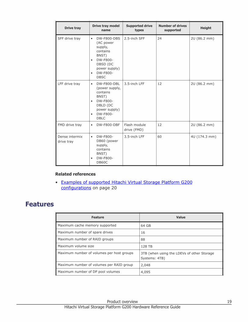
Drive tray Drive tray modelname
Supported drivetypes
Number of drivessupported Height
SFF drive tray • DW-F800-DBS(AC powersupply,containsBNST)
• DW-F800-DBSD (DCpower supply)
• DW-F800-DBSC
2.5-inch SFF 24 2U (86.2 mm)
LFF drive tray • DW-F800-DBL(power supply,containsBNST)
• DW-F800-DBLD (DCpower supply)
• DW-F800-DBLC
3.5-inch LFF 12 2U (86.2 mm)
FMD drive tray • DW-F800-DBF Flash moduledrive (FMD)
12 2U (86.2 mm)
Dense intermixdrive tray
• DW-F800-DB60 (powersupply,containsBNST)
• DW-F800-DB60C
3.5-inch LFF 60 4U (174.3 mm)
Related references
• Examples of supported Hitachi Virtual Storage Platform G200configurations on page 20
FeaturesFeature Value
Maximum cache memory supported 64 GB
Maximum number of spare drives 16
Maximum number of RAID groups 88
Maximum volume size 128 TB
Maximum number of volumes per host groups 3TB (when using the LDEVs of other StorageSystems: 4TB)
Maximum number of volumes per RAID group 2,048
Maximum number of DP pool volumes 4,095
Product overview 19Hitachi Virtual Storage Platform G200 Hardware Reference Guide

Feature Value
Maximum number of DP pools 64
Maximum number of Fibre Channel devicesconnected through a Fibre Channel switch
255
Maximum number of iSCSI hosts connectedthrough a network switch
255
ScalabilityAll storage systems offer pay-as-you-grow scalability by allowing you to hot-add drives as you need them.
Examples of supported Hitachi Virtual Storage Platform G200configurations
Controller Drive tray
Maximumnumber ofdrive trayssupported
Maximum number ofdrives supported
CBSS
SFF drive tray 7 192 HDDs or SSDs
LFF drive tray 7 108 HDDs or SSDs
FMD drive tray 7 108 FMDs
Dense intermixdrive tray
4264 HDDs or SSDs
Controller Drive tray
Maximumnumber ofdrive trayssupported
Maximum number ofdrives supported
CBSL
SFF drive tray 7 180 HDDs or SSDs
LFF drive tray 7 96 HDDs or SSDs
FMD drive tray 7 96 FMDs
Dense intermixdrive tray
4 252 HDDs or SSDs
Note: The Hitachi Virtual Storage Platform G200 includes the drive to beinstalled in the controller chassis.
Related references
• Hitachi Virtual Storage Platform G200 model on page 18
20 Product overviewHitachi Virtual Storage Platform G200 Hardware Reference Guide

Maximum number of mounted drive traysThe following table shows the maximum number of mountable drive traysand a maximum number of mountable drives for each drive type.
The values below include drives installed in the controller.
Controller Maximum drive trays Maximum number ofdrivesDrive trays Maximum number
CBSS SFF 7 192 HDDs or SSDs
LFF 7 108 HDDs or SSDs
FMD 7 108 FMDs
Dense intermix drive
tray
4 264 HDDs or SSDs
Controller Maximum drive trays Maximum number ofdrivesDrive trays Maximum number
CBSL SFF 7 180 HDDs or SSDs
LFF 7 96 HDDs or SSDs
FMD 7 96 FMDs
Dense intermix drive
tray
4 252 HDDs or SSDs
Controller
Number of mounted drivetrays (up to 7 per path)
Maximum number of mounteddrives
SFF, LFFdrives
Denseintermix drive
tray
SFF drive +dense
intermix drivetray
LFF drive +dense
intermixdrive tray
CBSS
7 0 192 108
5 1 204 144
3 2 216 180
1 3 228 216
0 4 264 264
The maximum number of drive trays that can be installed per path is 7.
Product overview 21Hitachi Virtual Storage Platform G200 Hardware Reference Guide

Controller
Number of mounted drivetrays (up to 8 per path)
Maximum number of mounteddrives
SFF, LFFdrives
Denseintermix drive
tray
SFF drive +dense
intermix drivetray
LFF drive +dense
intermixdrive tray
CBSL
7 0 180 96
5 1 192 132
3 2 204 168
1 3 216 204
0 4 252 252
The maximum number of drive trays that can be installed per path is 7.
Number of mounted drive trays (up to 10 perpath)
Maximum number of mounted drives
(up to 240 per path - see Note below)
SFF, LFF drives Dense intermix drivetray
SFF drive + denseintermix drive tray
LFF drive + denseintermix drive tray
48 0 1152 576
45 1 1140 600
44 2 1176 648
41 3 1164 672
40 4 1200 720
37 5 1188 744
36 6 1224 792
33 7 1212 816
32 8 1248 864
29 9 1236 888
28 10 1272 936
25 11 1260 960
24 12 1296 1008
21 13 1284 1032
20 14 1320 1080
17 15 1308 1104
16 16 1344 1152
13 17 1332 1176
12 18 1368 1224
9 19 1356 1248
22 Product overviewHitachi Virtual Storage Platform G200 Hardware Reference Guide

Number of mounted drive trays (up to 10 perpath)
Maximum number of mounted drives
(up to 240 per path - see Note below)
SFF, LFF drives Dense intermix drivetray
SFF drive + denseintermix drive tray
LFF drive + denseintermix drive tray
8 20 1392 1296
5 21 1380 1320
4 22 1416 1368
1 23 1404 1392
0 24 1440 1440
The maximum number of drive trays that can be installed per path is 8.
Product overview 23Hitachi Virtual Storage Platform G200 Hardware Reference Guide

24 Product overviewHitachi Virtual Storage Platform G200 Hardware Reference Guide

2Hardware description
The following sections describe the storage system hardware.
□ Storage system controllers
□ Controller interfaces
□ Storage system drive trays
□ Hitachi Virtual Storage Platform SVP server
Hardware description 25Hitachi Virtual Storage Platform G200 Hardware Reference Guide
Storage system controllersEvery storage system has two controllers. The controllers contain fans andpower supplies, and provide the interfaces between a host and the storagesystem.
A controller manages the I/O between the host system and data volumes.
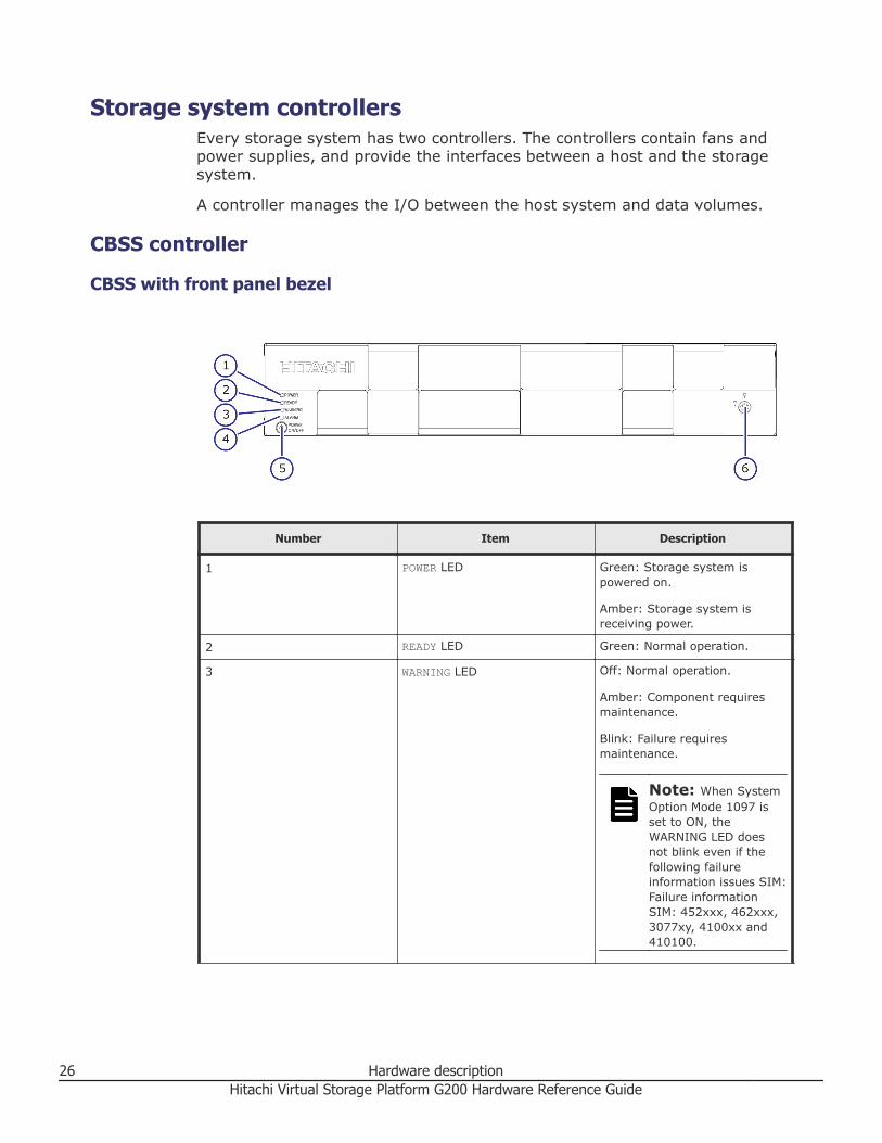
CBSS controller
CBSS with front panel bezel
Number Item Description
1 POWER LED Green: Storage system ispowered on.
Amber: Storage system isreceiving power.
2 READY LED Green: Normal operation.
3 WARNING LED Off: Normal operation.
Amber: Component requiresmaintenance.
Blink: Failure requiresmaintenance.
Note: When SystemOption Mode 1097 isset to ON, theWARNING LED doesnot blink even if thefollowing failureinformation issues SIM:Failure informationSIM: 452xxx, 462xxx,3077xy, 4100xx and410100.
26 Hardware descriptionHitachi Virtual Storage Platform G200 Hardware Reference Guide

Number Item Description
LED might go OFF during usermaintenance.
4 ALARM LED Off: Normal operation.
Red: Processor failure (systemmay be down). Go to theCustomer Contact Us page at https://support.hds.com/en_us/contact-us.html.
5 POWER ON/OFF (main switch) Powers the storage system.
6 Lock Locks and unlocks the frontpanel bezel by using thesupplied key.
Note: Removing a controller can cause the POWER, READY, WARNING, andALARM LEDs on the front panel to go off. These LEDs return to their on stateafter the storage system recovers from the controller replacement.
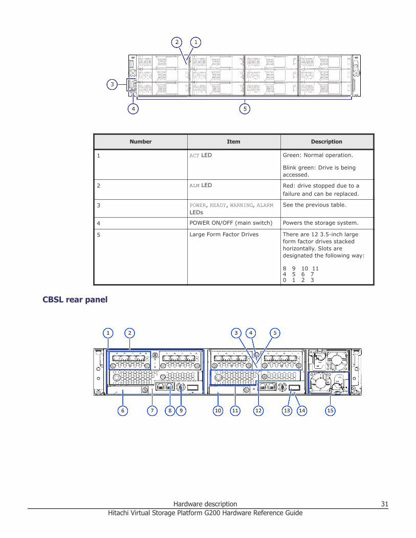
CBSS front panel without bezel
Number Item Description
1 ACT LED Green: Normal operation.
Blink green: Drive is beingaccessed.
2 ALM LED Red: drive stopped due to afailure and can be replaced.
3 POWER, READY, WARNING, ALARMLEDs
See the previous table.
4 POWER ON/OFF (main switch) Powers the storage system.
5 Small form factor drives There are 24 2.5-inch smallform factor drives oriented
Hardware description 27Hitachi Virtual Storage Platform G200 Hardware Reference Guide

Number Item Description
vertically. Slots are designated0-23 (left to right).
CBSS rear panel
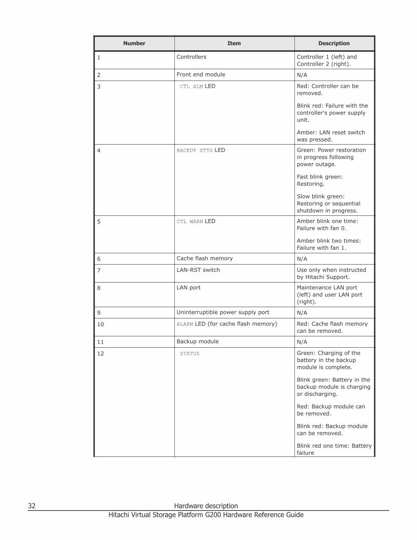
Number Item Description
1 Controllers Controller 1 (left) andController 2 (right).
2 Front end module N/A
3 CTL ALM LED Red: Controller can beremoved.
Blink red: Failure with thecontroller's power supplyunit.
Amber: LAN reset switchwas pressed.
4 BACKUP STTS LED Green: Power restorationin progress followingpower outage.
Fast blink green:Restoring.
Slow blink green:Restoring or sequentialshutdown in progress.
5 CTL WARN LED Amber blink one time:Failure with fan 0.
Amber blink two times:Failure with fan 1.
6 Cache flash memory N/A
7 LAN-RST switch Use only when instructedby Hitachi Support.
28 Hardware descriptionHitachi Virtual Storage Platform G200 Hardware Reference Guide

Number Item Description
8 LAN port Maintenance LAN port(left) and user LAN port(right).
9 Uninterruptible power supply port N/A
10 ALARM LED (for cache flash memory) Red: Cache flash memorycan be removed.
11 Backup module N/A
12 STATUS Green: Charging of thebattery in the backupmodule is complete.
Blink green: Battery in thebackup module is chargingor discharging.
Red: Backup module canbe removed.
Blink red: Backup modulecan be removed.
Blink red one time: Batteryfailure
Off: battery is notinstalled, failure occurred,or firmware is beingupgraded.
13 SAS port N/A
14 Port LED Blue: port link has beenmade.
15 Power supply unit N/A
CBSL controller
CBSL with front panel bezel
Hardware description 29Hitachi Virtual Storage Platform G200 Hardware Reference Guide

Number Item Description
1 POWER LED Green: Storage system ispowered on.
Amber: Storage system isreceiving power.
2 READY LED Green: Normal operation.
3 WARNING LED Off: Normal operation.
Amber: Component requiresmaintenance.
Blink: Failure requiresmaintenance.
Note: When SystemOption Mode 1097 isset to ON, theWARNING LED doesnot blink even if thefollowing failureinformation issues SIM:Failure informationSIM: 452xxx, 462xxx,3077xy, 4100xx and410100.
LED might go OFF during usermaintenance.
4 ALARM LED Off: Normal operation.
Red: Processor failure (systemmay be down). Go to theCustomer Contact Us page at https://support.hds.com/en_us/contact-us.html.
5 POWER ON/OFF (main switch) Powers the storage system.
6 Lock Locks and unlocks the frontpanel bezel by using thesupplied key.
Note: Removing a controller can cause the POWER, READY, WARNING, andALARM LEDs on the front panel to go off. These LEDs return to their on stateafter the storage system recovers from the controller replacement.
CBSL front panel without bezel
30 Hardware descriptionHitachi Virtual Storage Platform G200 Hardware Reference Guide
Number Item Description
1 ACT LED Green: Normal operation.
Blink green: Drive is beingaccessed.
2 ALM LED Red: drive stopped due to afailure and can be replaced.
3 POWER, READY, WARNING, ALARMLEDs
See the previous table.
4 POWER ON/OFF (main switch) Powers the storage system.
5 Large Form Factor Drives There are 12 3.5-inch largeform factor drives stackedhorizontally. Slots aredesignated the following way:
8 9 10 114 5 6 70 1 2 3
CBSL rear panel
Hardware description 31Hitachi Virtual Storage Platform G200 Hardware Reference Guide
Number Item Description
1 Controllers Controller 1 (left) andController 2 (right).
2 Front end module N/A
3 CTL ALM LED Red: Controller can beremoved.
Blink red: Failure with thecontroller's power supplyunit.
Amber: LAN reset switchwas pressed.
4 BACKUP STTS LED Green: Power restorationin progress followingpower outage.
Fast blink green:Restoring.
Slow blink green:Restoring or sequentialshutdown in progress.
5 CTL WARN LED Amber blink one time:Failure with fan 0.
Amber blink two times:Failure with fan 1.
6 Cache flash memory N/A
7 LAN-RST switch Use only when instructedby Hitachi Support.
8 LAN port Maintenance LAN port(left) and user LAN port(right).
9 Uninterruptible power supply port N/A
10 ALARM LED (for cache flash memory) Red: Cache flash memorycan be removed.
11 Backup module N/A
12 STATUS Green: Charging of thebattery in the backupmodule is complete.
Blink green: Battery in thebackup module is chargingor discharging.
Red: Backup module canbe removed.
Blink red: Backup modulecan be removed.
Blink red one time: Batteryfailure
32 Hardware descriptionHitachi Virtual Storage Platform G200 Hardware Reference Guide
Number Item Description
Off: battery is notinstalled, failure occurred,or firmware is beingupgraded.
13 SAS port N/A
14 Port LED Blue: port link has beenmade.
15 Power supply unit N/A
Controller interfacesControllers provide interfaces for connecting, powering, and configuring andmanaging the storage system. They also have LEDs to show the status of thestorage system.
Front end module descriptions
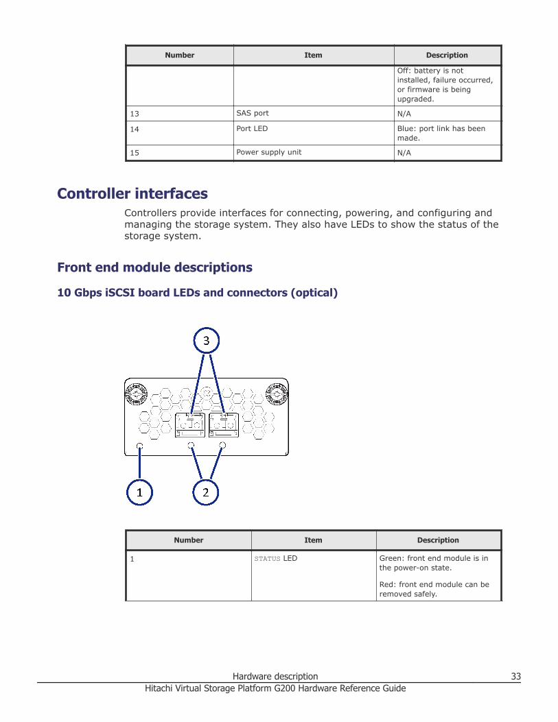
10 Gbps iSCSI board LEDs and connectors (optical)
Number Item Description
1 STATUS LED Green: front end module is inthe power-on state.
Red: front end module can beremoved safely.
Hardware description 33Hitachi Virtual Storage Platform G200 Hardware Reference Guide
Number Item Description
2 PORT LED Red: Small form-factorpluggable can be removed.
Blue: Normal link status.
Blink blue: Front end module isin communication status.
3 iSCSI connectors Connect to Ethernet LANcables.
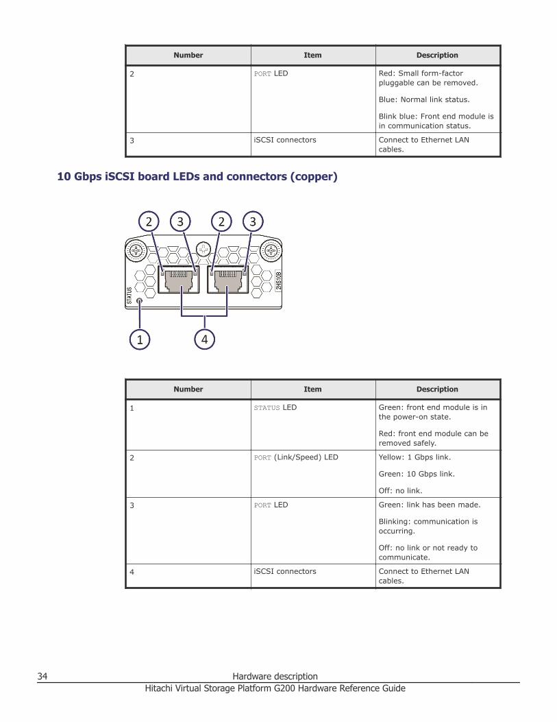
10 Gbps iSCSI board LEDs and connectors (copper)
Number Item Description
1 STATUS LED Green: front end module is inthe power-on state.
Red: front end module can beremoved safely.
2 PORT (Link/Speed) LED Yellow: 1 Gbps link.
Green: 10 Gbps link.
Off: no link.
3 PORT LED Green: link has been made.
Blinking: communication isoccurring.
Off: no link or not ready tocommunicate.
4 iSCSI connectors Connect to Ethernet LANcables.
34 Hardware descriptionHitachi Virtual Storage Platform G200 Hardware Reference Guide

8/16/32 Gbps Fibre Channel (4-port) board LEDs and connectors
Table 1 8 Gbps Fibre Channel
Number Item Description
1 Fibre Channel connectors Connect to Fibre Channelcables.
2 STATUS LED Green: front end module is inpower-on state.
Red: front end module can beremoved safely.
3 PORT LED Red: Small form-factorpluggable can be removed.
Blue: Normal link status at 8Gbps.
Green: Normal link status at 2Gbps or 4 Gbps.
Table 2 32/16 Gbps Fibre Channel
Number Item Description
1 Fibre Channel connectors Connect to Fibre Channelcables.
2 STATUS LED Green: front end module is inpower-on state.
Red: front end module can beremoved safely.
3 PORT LED Red: Small form-factorpluggable can be removed.
Hardware description 35Hitachi Virtual Storage Platform G200 Hardware Reference Guide
Number Item Description
Blue: Normal link status at 16Gbps (16 Gbps).
Blue: Normal link status at 32Gbps (32 Gbps).
Green: Normal link status at 4Gbps or 8 Gbps (16 Gbps).
Green: Normal link status at 8Gbps or 16 Gbps (32 Gbps).
Port Assignments
CHB#8/16/32 Gbps Fibre Channel Ports (left to right)
Port 1 Port 2 Port 3 Port 4
CHB-1A 1A 3A 5A 7A
CHB-1B 1B 3B 5B 7B
CHB-1C 1C 3C 5C 7C
CHB-1D 1D 3D 5D 7D
CHB-1E 1E 3E 5E 7E
CHB-1F 1F 3F 5F 7F
CHB-1G 1G 3G 5G 7G
CHB-1H 1H 3H 5H 7H
CHB-2A 2A 4A 6A 8A
CHB-2B 2B 4B 6B 8B
CHB-2C 2C 4C 6C 8C
CHB-2D 2D 4D 6D 8D
CHB-2E 2E 4E 6E 8E
CHB-2F 2F 4F 6F 8F
CHB-2G 2G 4G 6G 8G
CHB-2H 2H 4H 6H 8H
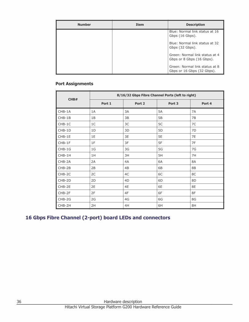
16 Gbps Fibre Channel (2-port) board LEDs and connectors
36 Hardware descriptionHitachi Virtual Storage Platform G200 Hardware Reference Guide

Number Item Description
1 STATUS LED Green: front end module is inthe power-on state.
Red: front end module can beremoved safely.
2 PORT LED Red: Small form-factorpluggable can be removed.
Blue: normal link status at 16Gbps.
Green: normal link status at 4or 8 Gbps.
3 Fibre Channel connectors Connect to Fibre Channelcables.
Port Assignments
CHB#16 Gbps Fibre Channel Ports (left to right)
Port 1 Port 2
CHB-1A 1A 3A
CHB-1B 1B 3B
CHB-1C 1C 3C
CHB-1D 1D 3D
CHB-1E 1E 3E
CHB-1F 1F 3F
CHB-1G 1G 3G
CHB-1H 1H 3H
CHB-2A 2A 4A
CHB-2B 2B 4B
CHB-2C 2C 4C
Hardware description 37Hitachi Virtual Storage Platform G200 Hardware Reference Guide

CHB#16 Gbps Fibre Channel Ports (left to right)
Port 1 Port 2
CHB-2D 2D 4D
CHB-2E 2E 4E
CHB-2F 2F 4F
CHB-2G 2G 4G
CHB-2H 2H 4H
LAN blade LEDs and connectors
Number LED or connector Description
1 ACT LED Green: data is beingtransferred.
2 LINK LED Green: link status is normal.
3 LAN 2 LAN port used by the user.
4 LAN 1 Maintenance LAN port used byservice personnel.
5 LAN ALARM LED Red: LAN blade can beremoved.
6 Uninterruptible power supplyport
Only supported in Japandomestic market.
Back end module LEDs and connectors
38 Hardware descriptionHitachi Virtual Storage Platform G200 Hardware Reference Guide
Number Item Description
1 PATH 1 connector Connect to a drive tray.
2 PORT LED Blue: Normal link status.
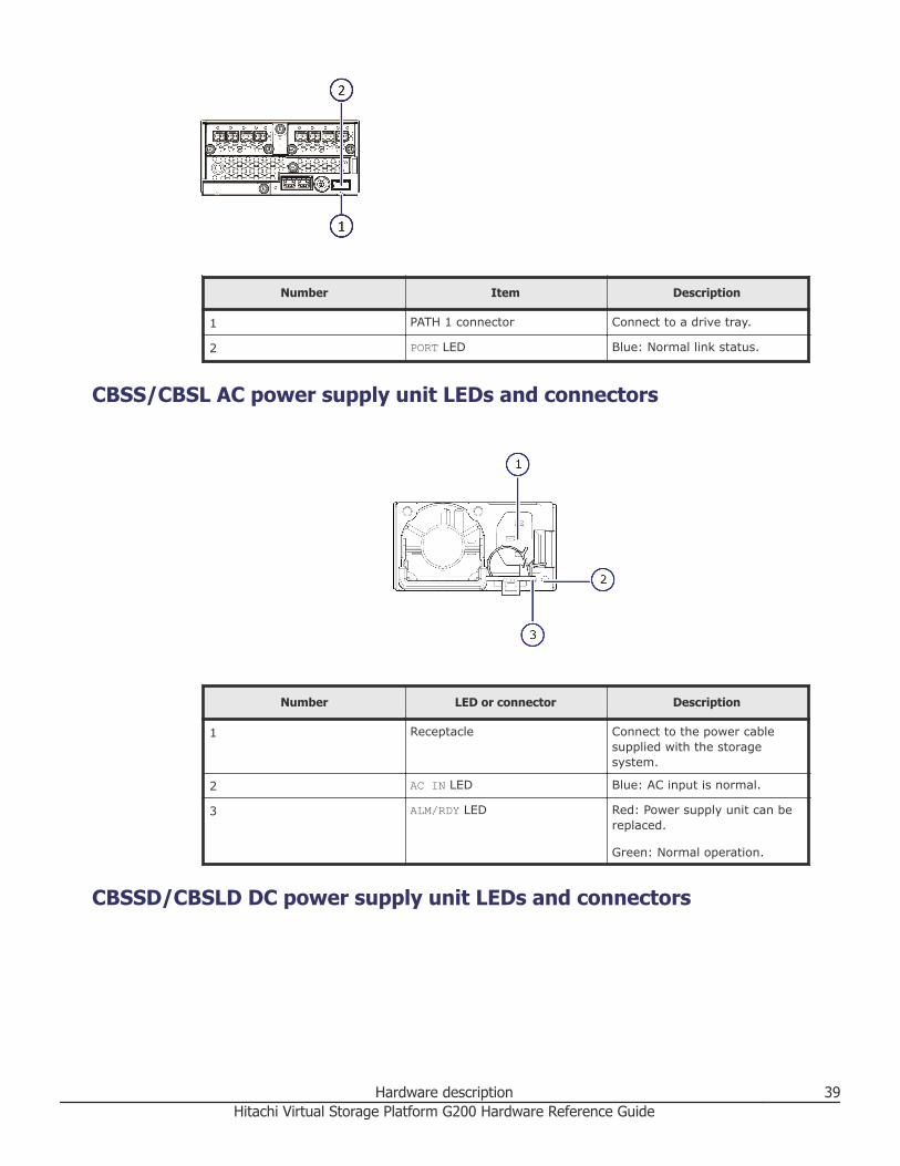
CBSS/CBSL AC power supply unit LEDs and connectors
Number LED or connector Description
1 Receptacle Connect to the power cablesupplied with the storagesystem.
2 AC IN LED Blue: AC input is normal.
3 ALM/RDY LED Red: Power supply unit can bereplaced.
Green: Normal operation.
CBSSD/CBSLD DC power supply unit LEDs and connectors
Hardware description 39Hitachi Virtual Storage Platform G200 Hardware Reference Guide

Number Item Description
1 ALM/RDY LED Red: Power supply unit can bereplaced.
Green: Normal operation.
2 DC IN LED Blue: DC input is normal.
Storage system drive traysDrive trays contain drives, power supplies, fans, and status LEDs. They alsoprovide interfaces for connecting to controllers and other drive trays.
Small form factor (SFF) drive tray
SFF with front panel bezel
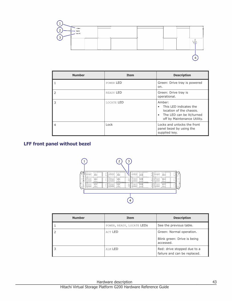
Number Item Description
1 POWER LED Green: Drive tray is poweredon.
40 Hardware descriptionHitachi Virtual Storage Platform G200 Hardware Reference Guide

Number Item Description
2 READY LED Green: Drive tray isoperational.
3 LOCATE LED Amber:• This LED indicates the
location of the chassis thatdetects a failure.
• The LED can be lit/turnedoff by Maintenance Utility tospecify the chassis location.
4 Lock Locks and unlocks the frontpanel bezel by using thesupplied key.
SFF front panel without bezel
Number Item Description
1 ACT LED Green: Normal operation.
Blink green: Drive is beingaccessed.
2 ALM LED Red: drive stopped due to afailure and can be replaced.
3 POWER, READY, LOCATE LEDs See the previous table.
4 Small form factor drives There are 24 2.5-inch smallform factor drives orientedvertically. Slots are designated0-23 (left to right).
Hardware description 41Hitachi Virtual Storage Platform G200 Hardware Reference Guide

SFF rear panel
Number Item Description
1 ENC N/A
2 POWER LED Green: ENC is in the power-onstate.
3 LOCATE LED • This LED indicates thelocation of the chassis.
• The LED can be lit or turnedoff by the maintenanceutility.
4 ALARM LED Red: ENC can be replaced.
5 PATH (IN) LED Blue: IN side port is linked up.
6 PATH (IN) connector Connect to a controller or drivetray.
7 PATH (OUT)LED Blue: OUT side port is linkedup.
8 PATH (OUT) connector Connect to a drive tray.
9 Console This port is reserved.
10 Power supply unit N/A
11 Receptacle Connect to the power cablesupplied with the storagesystem.
12 AC IN LED Green: Normal operation.
13 ALM LED Red: Power supply unit can bereplaced.
14 RDY LED Green: Normal operation.
Large form factor (LFF) drive tray
LFF with front panel bezel
42 Hardware descriptionHitachi Virtual Storage Platform G200 Hardware Reference Guide
Number Item Description
1 POWER LED Green: Drive tray is poweredon.
2 READY LED Green: Drive tray isoperational.
3 LOCATE LED Amber:• This LED indicates the
location of the chassis.• The LED can be lit/turned
off by Maintenance Utility.
4 Lock Locks and unlocks the frontpanel bezel by using thesupplied key.
LFF front panel without bezel
Number Item Description
1 POWER, READY, LOCATE LEDs See the previous table.
2 ACT LED Green: Normal operation.
Blink green: Drive is beingaccessed.
3 ALM LED Red: drive stopped due to afailure and can be replaced.
Hardware description 43Hitachi Virtual Storage Platform G200 Hardware Reference Guide
Number Item Description
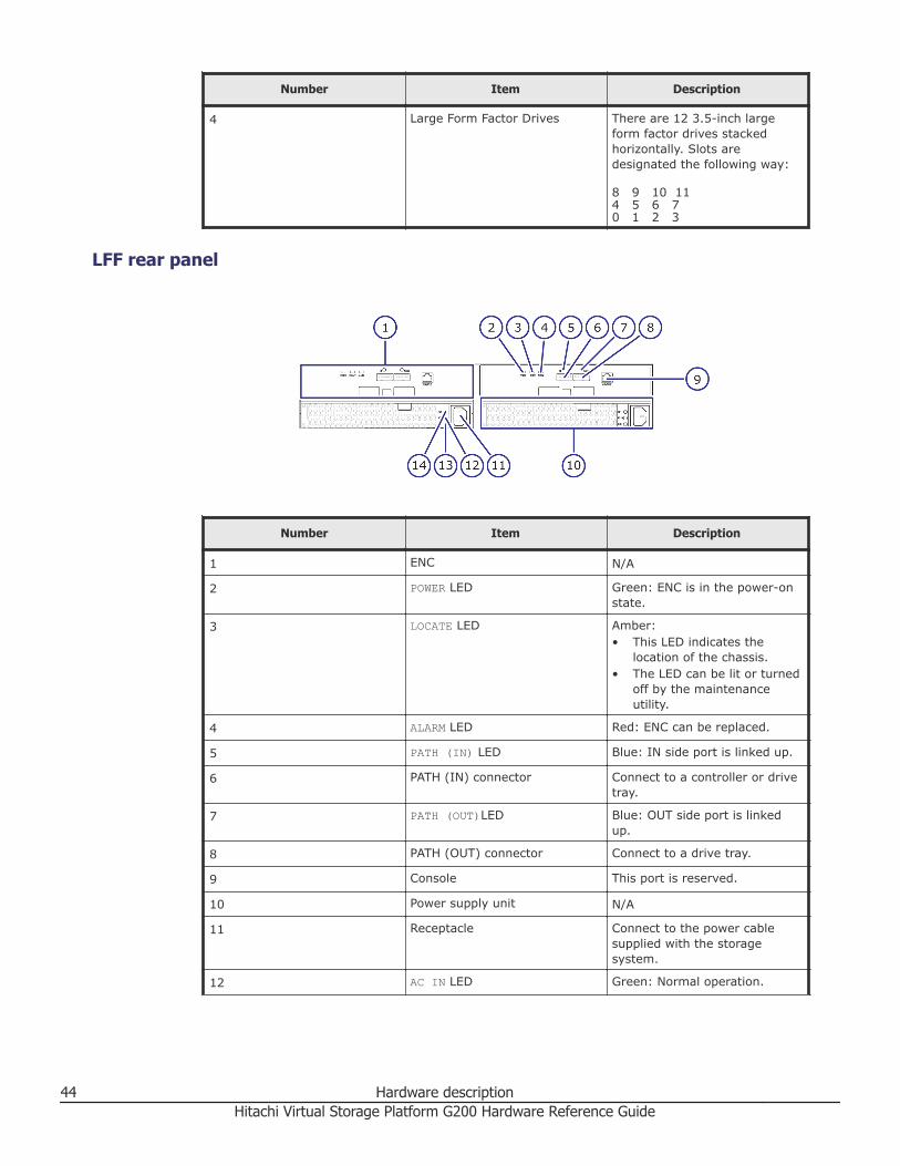
4 Large Form Factor Drives There are 12 3.5-inch largeform factor drives stackedhorizontally. Slots aredesignated the following way:
8 9 10 114 5 6 70 1 2 3
LFF rear panel
Number Item Description
1 ENC N/A
2 POWER LED Green: ENC is in the power-onstate.
3 LOCATE LED Amber:• This LED indicates the
location of the chassis.• The LED can be lit or turned
off by the maintenanceutility.
4 ALARM LED Red: ENC can be replaced.
5 PATH (IN) LED Blue: IN side port is linked up.
6 PATH (IN) connector Connect to a controller or drivetray.
7 PATH (OUT)LED Blue: OUT side port is linkedup.
8 PATH (OUT) connector Connect to a drive tray.
9 Console This port is reserved.
10 Power supply unit N/A
11 Receptacle Connect to the power cablesupplied with the storagesystem.
12 AC IN LED Green: Normal operation.
44 Hardware descriptionHitachi Virtual Storage Platform G200 Hardware Reference Guide

Number Item Description
13 ALM LED Red: Power supply unit can bereplaced.
14 RDY LED Green: Normal operation.
Flash module drive (FMD) tray
FMD with front panel bezel
Number Item Description
1 POWER LED Green: Drive tray is poweredon.
2 READY LED Green: Drive tray isoperational.
3 LOCATE LED Amber:• This LED indicates the
location of the chassis.• The LED can be lit or turned
off by the maintenanceutility.
4 Lock Locks and unlocks the frontpanel bezel by using thesupplied key.
FMD front panel without bezel
Hardware description 45Hitachi Virtual Storage Platform G200 Hardware Reference Guide

Number Item Description
1 2 ACT LED Green: Normal operation.
Blink: drive is being accessed.
Slow blink:• DKC-F710I-1R6FM/3R2FM:
insufficient battery capacityin the flash module drive.
• DKC-F810I-1R6FN/3R2FN/6R4FN: flash module drivebuilt-in capacitor is charged.If the storage system isturned on, the LED stopsblinking when the capacitoris charged completely(about two minutes).
Note: ACT indicatoris only printed on sometypes of FMDs.
ALM LED Red: Drive stopped due to afailure and can be replaced.
Note: ALM indicatoris only printed on sometypes of FMDs.
3 POWER, READY, LOCATE LEDs See the previous table.
46 Hardware descriptionHitachi Virtual Storage Platform G200 Hardware Reference Guide

Number Item Description
4 Flash module drives Twelve flash module drives.Slots are designated thefollowing way:
9, 10, 11
6, 7, 8
3, 4, 5
0, 1, 2
FMD rear panel
Number Item Description
1 ENC N/A
2 POWER LED Green: ENC is in the power-onstate.
3 LOCATE LED Amber:• This LED indicates the
location of the chassis.• The LED can be lit or turned
off by the maintenanceutility.
4 ALARM LED Red: ENC can be replaced.
5 PATH (IN) LED Blue: IN side port is linked up.
6 PATH (IN) connector Connect to a controller or drivetray.
7 PATH (OUT)LED Blue: OUT side port is linkedup.
8 PATH (OUT) connector Connect to a drive tray.
9 Console This port is reserved.
Hardware description 47Hitachi Virtual Storage Platform G200 Hardware Reference Guide

Number Item Description
10 Receptacle Connect to the power cablesupplied with the storagesystem.
11 Three LEDS, top to bottom:
RDY LED Green: power supply unit isoperating normally.
AC IN LED Green: power supply unit isoperating normally.
ALM REPLACE LED Red: power supply unit can bereplaced.
Dense intermix drive tray
Dense intermix drive tray with front panel bezel
Number Item Description
1 POWER LED Green: Drive tray is poweredon.
2 READY LED Green: Drive tray isoperational.
3 LOCATE LED Amber:• This LED indicates the
location of the chassis.• The LED can be lit or turned
off by the maintenanceutility.
4 Lock Locks and unlocks the frontpanel bezel by using thesupplied key.
48 Hardware descriptionHitachi Virtual Storage Platform G200 Hardware Reference Guide

Dense intermix drive tray display LEDs
Number Item Description
1 ACT Green: Normal operation.
Blink green: Drive is beingaccessed.
2 ALM LED Red: Drive stopped due to afailure and can be replaced.
Note: Drives are organized as follows, starting from the rear of the drive trayand moving left to right. In the above figure on the left, the rear of the drivetray is at the top.• Rear of drive tray: 48 - 59• 36 - 47• 24 - 35• 12 - 23• Front of drive tray: 00 - 11
Dense intermix drive tray rear panel
Hardware description 49Hitachi Virtual Storage Platform G200 Hardware Reference Guide
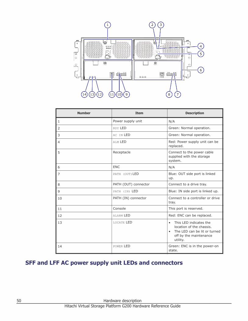
Number Item Description
1 Power supply unit N/A
2 RDY LED Green: Normal operation.
3 AC IN LED Green: Normal operation.
4 ALM LED Red: Power supply unit can bereplaced.
5 Receptacle Connect to the power cablesupplied with the storagesystem.
6 ENC N/A
7 PATH (OUT)LED Blue: OUT side port is linkedup.
8 PATH (OUT) connector Connect to a drive tray.
9 PATH (IN) LED Blue: IN side port is linked up.
10 PATH (IN) connector Connect to a controller or drivetray.
11 Console This port is reserved.
12 ALARM LED Red: ENC can be replaced.
13 LOCATE LED • This LED indicates thelocation of the chassis.
• The LED can be lit or turnedoff by the maintenanceutility.
14 POWER LED Green: ENC is in the power-onstate.
SFF and LFF AC power supply unit LEDs and connectors
50 Hardware descriptionHitachi Virtual Storage Platform G200 Hardware Reference Guide

Number Item Description
1 RDY LED Green: Normal operation.
2 AC IN LED Green: AC input is operatingnormally.
3 ALM LED Red: Power supply unit can bereplaced.
SFF and LFF DC power supply unit LEDs and connectors
Number Item Description
1 RDY LED Green: Normal operation.
2 DC IN LED Green: DC input is operatingnormally.
3 ALM LED Red: Power supply unit can bereplaced.
Hitachi Virtual Storage Platform SVP serverThe following sections describe the physical SVP. The SVP is also available asa virtual management server that runs on a VMware ESXi host or as aphysical management server that runs on a customer-supplied server.
Hardware description 51Hitachi Virtual Storage Platform G200 Hardware Reference Guide

Service processor descriptionVSP Gx00 models include a separate, dedicated 1U service processor (SVP)to host an element manager (Hitachi Device Manager - Storage Navigator).The SVP (model number 3919435.P) operates independently from thestorage system's CPU and operating system, and provides out‑of‑bandconfiguration and management of the storage system. It also collectsperformance data for key components of the storage system to enablediagnostic testing and analysis.
Note: This product is also designed for IT power distribution systems withphase-to-phase voltage.
The SVP runs Microsoft Windows Embedded Standard 7. This operatingsystem provides the same look and feel and desktop environment asMicrosoft Windows 7 Professional.
The SVP provides four RJ-45 ports:• Two ports connect to the storage system controllers (one port for each
controller).• One port connects to the user's IP network.• One port connects to a user-supplied management console PC.
Three of the four RJ-45 ports (the ones that connect to the controllers andthe IP network) are configured as a bridge. The SVP can be addressed usingthe default IP address 192.168.0.15.
In the unlikely event you cannot connect to the SVP using the default IPaddress, use the following emergency login: http://<default SVP IP address>/dev/storage/<model number><system serial number>/emergency.do. For example:
Storage system modelnumber
Storage system serialnumber
URL
8320004 456789 http://192.168.0.15/dev/
storage/8320004456789/
emergency.do
8340004 456789 http://192.168.0.15/dev/
storage/8340004456789/
emergency.do
8360004 456789 http://192.168.0.15/dev/
storage/8360004456789/
emergency.do
Users are responsible for adopting the appropriate security procedures withthe SVP, including:• Applying Windows security patches.
52 Hardware descriptionHitachi Virtual Storage Platform G200 Hardware Reference Guide

• Turning on automatic Windows updates or using the manual Windowsupdate method.
• Installing antivirus software that has been tested and approved by Hitachi.
SVP front panelThe SVP front panel has LEDs, a reset button, and a power button.
Number Description
1 LEDs. From left to right, the LEDs are:• BMC Heartbeat• LAN card 2• LAN card 1• Hard drive• System standby power
2 Reset button.
3 Power button. Applies power to or removespower from the SVP.
SVP rear panelThe only ports used on the rear panel of the SVP are the power socket andthe four LAN ports.
Hardware description 53Hitachi Virtual Storage Platform G200 Hardware Reference Guide
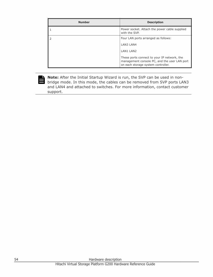
Number Description
1 Power socket. Attach the power cable suppliedwith the SVP.
2 Four LAN ports arranged as follows:
LAN3 LAN4
LAN1 LAN2
These ports connect to your IP network, themanagement console PC, and the user LAN porton each storage system controller.
Note: After the Initial Startup Wizard is run, the SVP can be used in non-bridge mode. In this mode, the cables can be removed from SVP ports LAN3and LAN4 and attached to switches. For more information, contact customersupport.
54 Hardware descriptionHitachi Virtual Storage Platform G200 Hardware Reference Guide

3System option modes
□ System Option Modes
System option modes 55Hitachi Virtual Storage Platform G200 Hardware Reference Guide

System Option ModesSystem Option Modes allow VSP Gx00 models to be configured to specificcustomer operating requirements.
At installation, the modes are set to their default values, as shown in thefollowing table. If you think these mode settings should be changed, discussthese settings with your Hitachi Data Systems team. The System OptionModes can be changed by a Hitachi Data Systems representative only.
The following table was up to date at the time this manual was published.However, the System Option Mode information might change in firmwarereleases that precede the next release of this manual. Contact your HitachiData Systems team for the latest information about System Option Modes.
The System Option Mode information includes:• Mode = specifies the System Option Mode number• Description = describes the action or function that the mode provides.• Default = specifies the default setting (ON or OFF) of the mode.
Note: These modes are supported by all firmware versions.
Mode Description Default
15 The mode can improve the host response time to be aboutwithin 6 seconds.
Note:
1. The mode applies when a drive response delay mayaffect business operations.
2. If Dynamic Sparing or Auto Correction Mode is used dueto host I/O conflicts with copy processing, I/O watchingtime is 30 seconds even the mode is set to ON.
3. Even though System Option Mode 015 is set to ON, thefunction does not apply to SATA or NL-SAS drives.
ON
22 Regarding the correction copy or the drive copy, in caseECCs/LRC PINs are set on the track of copy source HDD,mode 22 can be used to interrupt the copy processing(default) or to create ECCs/LRC PINs on the track of copytarget HDD to continue the processing.
Mode 22 = ON:
If ECCs/LRC PINs (up to 16*1) have been set on the trackof copy source HDD, ECCs/LRC PINs (up to 16*1) will becreated on the track of copy target HDD so that the copyprocessing will continue.
OFF
56 System option modesHitachi Virtual Storage Platform G200 Hardware Reference Guide

If the number of ECCs/LRC PINs exceeds the maximum, thecorresponding copy processing will be interrupted.
*1: The maximum number of ECCs/LRC PINs is as follows.
< For HUS VM>
73-03-01-00/00 or higher: 64
Earlier than 73-03-01-00/00: 16
Mode 22 = OFF:
If ECCs/LRC PINs have been set on the track of copy sourceHDD, the copy processing will be interrupted.
(first recover ECCs/LRC PINs by using the PIN recovery flow,and then perform the correction copy or the drive copyagain)
One of the controlling option for correction/drive copy.
80 For HUS VM (SI for OPEN)
In response to the Restore instruction from the host, ifneither Quick nor Normal is specified, the followingoperation is performed.
Mode 80 = ON:
Normal Restore (Reverse Copy) is performed.
Mode 80 = OFF:
Quick Restore is performed.
Notes:
1. This mode is applied when the specification for Restore ofSI is switched between Quick (default) and Normal.
2. The performance of Restore differs depending on theNormal or Quick specification.
OFF
87 HUS VM: Determining which of NormalCopy or QuickResync,
if not specified, is performed at the execution of pairresync
by RAID Manager. If ON, QuickResync, or if OFF,
NormalCopy is performed.
OFF
122 For Split or Resync request from the Mainframe host andStorage Navigator,
Mode 122 = ON:
By specifying Split or Resync, Steady/Quick Split or Normal/Quick Resync is respectively executed in accordance withNormal/Quick setting.
Mode 122 = OFF:
By specifying Split or Resync, Steady/Quick Split or Normal/Quick Resync is respectively executed in accordance withNormal/Quick setting.
For details, see the System Option Mode 122 sheet.
OFF
System option modes 57Hitachi Virtual Storage Platform G200 Hardware Reference Guide

Notes:
(1) For HUS VM, this mode is applied to use scripts etc thatare used on Lightning 9900 and Lightning 9900 V.
(2) Executing the pairresync command from RAID Managermay be related to the System Option Mode 087 setting.
(3) When performing At-Time Split from RAID Manager,
Set this mode to OFF or specify the environment variableHORCC_SPLT for Quick.
Otherwise, Pairsplit may turn timeout.
(4) The mode becomes effective after specifying Split/Resync following the mode setting. The mode function doesnot work if it is set during the Split/Resync operation.
292 Issuing OLS when Switching Port
In case the mainframe host (FICON) is connected with theCNT-made FC switch (FC9000 etc.), and is using along withthe TrueCopy S/390 with Open Fibre connection, theoccurrence of Link Incident Report for the mainframe hostfrom the FC switch will be deterred when switching the CHTport attribute (including automatic switching whenexecuting CESTPATH and CDELPATH in case of Mode114=ON).
Mode 292=ON:
When switching the port attribute, issue the OLS (100 ms)first, and then reset the Chip.
Mode 292=OFF:
When switching the port attribute, reset the Chip withoutissuing the OLS.
OFF
310 Mode 310 = ON:
The monitoring timer for MP hang-up is 6 seconds andreturning a response to the host within 8 is guaranteed.
Mode 310 = OFF:
The monitoring timer for MP hang-up remains 15 seconds(USP/NSC / USP V/VM) or 8 seconds (VSP/ VSP G1000).
Notes:
(1) This mode applies to a site where strict host responseperformance is required.
(2) If a hardware failure occurs when the mode is set to ON,the time until MPB blockage is determined is shorter thanusual.
OFF
448 Mode 448 = ON: (Enabled)
If the SVP detects a blocked path, the SVP assumes that anerror occurred, and then immediately splits (suspends) themirror.
Mode 448 = OFF: (Disabled)
N/A
58 System option modesHitachi Virtual Storage Platform G200 Hardware Reference Guide
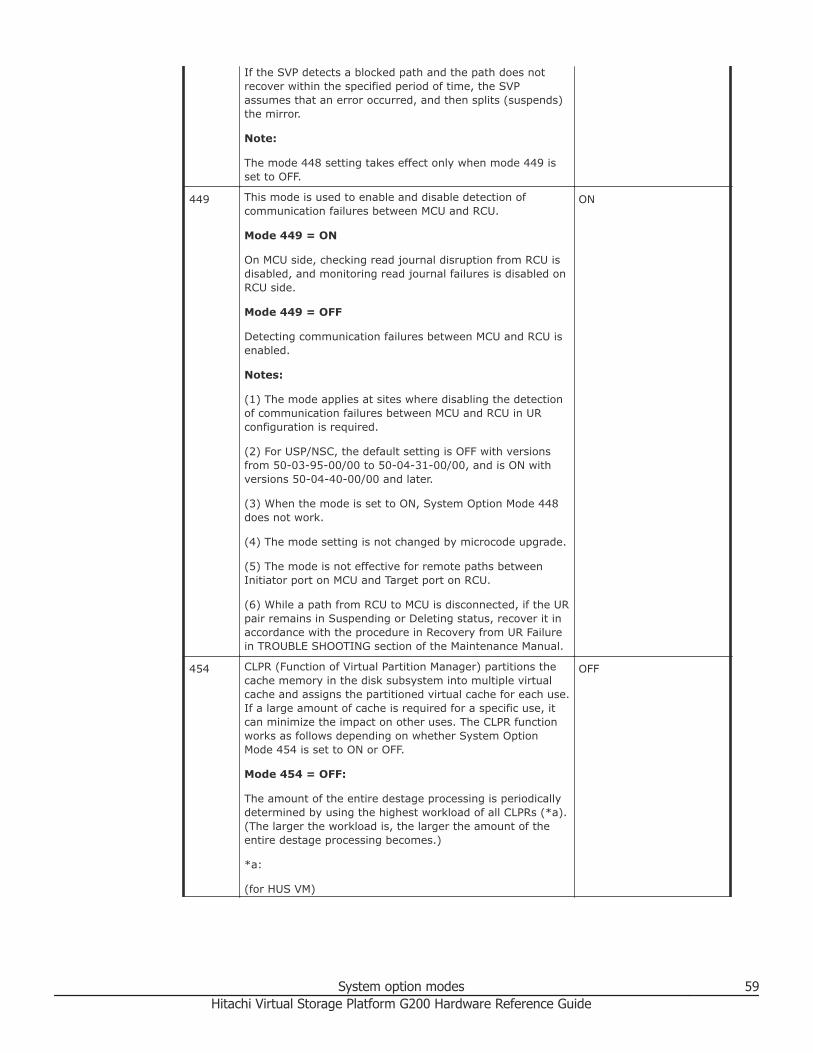
If the SVP detects a blocked path and the path does notrecover within the specified period of time, the SVPassumes that an error occurred, and then splits (suspends)the mirror.
Note:
The mode 448 setting takes effect only when mode 449 isset to OFF.
449 This mode is used to enable and disable detection ofcommunication failures between MCU and RCU.
Mode 449 = ON
On MCU side, checking read journal disruption from RCU isdisabled, and monitoring read journal failures is disabled onRCU side.
Mode 449 = OFF
Detecting communication failures between MCU and RCU isenabled.
Notes:
(1) The mode applies at sites where disabling the detectionof communication failures between MCU and RCU in URconfiguration is required.
(2) For USP/NSC, the default setting is OFF with versionsfrom 50-03-95-00/00 to 50-04-31-00/00, and is ON withversions 50-04-40-00/00 and later.
(3) When the mode is set to ON, System Option Mode 448does not work.
(4) The mode setting is not changed by microcode upgrade.
(5) The mode is not effective for remote paths betweenInitiator port on MCU and Target port on RCU.
(6) While a path from RCU to MCU is disconnected, if the URpair remains in Suspending or Deleting status, recover it inaccordance with the procedure in Recovery from UR Failurein TROUBLE SHOOTING section of the Maintenance Manual.
ON
454 CLPR (Function of Virtual Partition Manager) partitions thecache memory in the disk subsystem into multiple virtualcache and assigns the partitioned virtual cache for each use.If a large amount of cache is required for a specific use, itcan minimize the impact on other uses. The CLPR functionworks as follows depending on whether System OptionMode 454 is set to ON or OFF.
Mode 454 = OFF:
The amount of the entire destage processing is periodicallydetermined by using the highest workload of all CLPRs (*a).(The larger the workload is, the larger the amount of theentire destage processing becomes.)
*a:
(for HUS VM)
OFF
System option modes 59Hitachi Virtual Storage Platform G200 Hardware Reference Guide

(Write Pending capacity of CLPR#x of concerned MPB) ÷
(Cache capacity of CLPR#x of concerned MPB), x=0 to 31
CLPR whose value above is the highest of all CLPRs
Because the destage processing would be accelerateddepending on CLPR with high workload, when the workloadin a specific CLPR increases, the risk of host I/O halt wouldbe reduced.
Therefore, set Mode 454 to OFF in most cases.
Mode 454 = ON:
The amount of the entire destage processing is periodicallydetermined by using the workload of the entire system (*b).(The larger the workload is, the larger the amount of theentire destage processing becomes.)
*b:
(for HUS VM)
(Write Pending capacity of the entire system of concernedMPB) ÷ (Cache capacity of the entire system of concernedMPB)
Because the destage processing would not be acceleratedeven if CLPR has high workload, when the workload in aspecific CLPR increases, the risk of host I/O halt would beincreased. Therefore, it is limited to set Mode 454 to ONonly when a CLPR has constant high workload and it givespriority to I/O performance in a CLPR with low workloadthan host I/O halt in the CLPR with high workload.
Notes:
(1) When this System Option Mode is set to ON, even ifthere is an overloaded CLPR (CLPR with large Write Pendingcapacity), the amount of destage processing would notincrease easily. Therefore TOV(MIH) may occur in theoverloaded CLPR. Set this System Option Mode to ON onlywhen the overloaded state of a specific CLPR would notaffect other CLPRs.
In the case where the HUR function is used, if user volumesand journal volumes are defined in different CLPRs, whenthe CLPR to which the journal volumes are assignedoverflows, the user volumes become inaccessible either.Therefore it is recommended to set this System OptionMode to OFF.
(2) Because the destage processing will have a lowerpriority in the overloaded CLPR, the overloaded state of theoverloaded CLPR is not removed, and TOV(MIH) may occur.
457 (1) High Speed LDEV Format for External Volumes
The high speed LDEV format for external volumes isavailable by setting System Option Mode 457 to ON. IfSystem Option Mode 457 is ON, when selecting the externalvolume group and performing the LDEV format, any Writeprocessing on the external LUs will be skipped. However, if
OFF
60 System option modesHitachi Virtual Storage Platform G200 Hardware Reference Guide

the emulation type of the external LDEV is a mainframesystem, the Write processing for mainframe controlinformation only will be performed after the write skip.
(2) Support for Mainframe Control Block Write GUI
In case of System Option Mode 457 On, the high speedLDEV format for external volumes was supported at V03.Since V04, Control Block Write of the external LDEVs inMainframe emulation has been supported by StorageNavigator (GUI).
- In case the LDEV is not written with data “0” beforeperforming the function, the LDEV format may fail.
- After the format processing, make sure to set SystemOption Mode 457 to OFF.
459 PAIR → PSUS(SP) → PSUS: System Option Mode 459function is running at copy pending from P-VOL to S-VOLsuch as PSUS(SP) → PSUS. Please refer additional TAB ofmode list.
Mode 459 = ON:
Waits for cache memory to completely destage the DKC S-Vol to the External Volume S-Vol before changing pair statusto SUSPEND.
Mode 459 = OFF:
The status changes to SUSPEND as soon as all the deltadata is copied to S-Vol cache. The status does not wait forcache to destage to the S-Vol external volume.
OFF
466 Universal Replicator recommends the line band of 100 Mbpsor more for the path between Main and Remote. However,when a customer uses the line band of around 10 Mbps,operation on UR cannot be properly processed. As a result,many retries occur and UR may suspend. This mode isprovided to guarantee the line band of at least 10 Mbps forproper system operation.
Mode 466 = ON:
The line band of 10 Mbps or more is available. The JNL readis performed with 4-multiplexed read size of 256 KB.
Mode 466 = OFF:
The same as the conventional operation. The line band of100 Mbps or more is available. The JNL read is performedwith 32-multiplexed read size of 1 MB by default.
Note that the line band can be changed from the window forchanging JNL group options.
OFF
467 In case of using the following features, the current copyprocessing slows down if the dirty percentage is 60% orlarger, and it stops if the dirty percentage is 75% or larger.Mode 467 is to prevent the dirty percentage from over 60%so that the host performance is not affected.
ON
System option modes 61Hitachi Virtual Storage Platform G200 Hardware Reference Guide
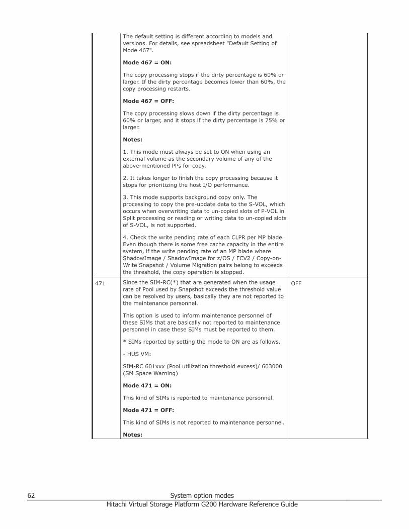
The default setting is different according to models andversions. For details, see spreadsheet "Default Setting ofMode 467".
Mode 467 = ON:
The copy processing stops if the dirty percentage is 60% orlarger. If the dirty percentage becomes lower than 60%, thecopy processing restarts.
Mode 467 = OFF:
The copy processing slows down if the dirty percentage is60% or larger, and it stops if the dirty percentage is 75% orlarger.
Notes:
1. This mode must always be set to ON when using anexternal volume as the secondary volume of any of theabove-mentioned PPs for copy.
2. It takes longer to finish the copy processing because itstops for prioritizing the host I/O performance.
3. This mode supports background copy only. Theprocessing to copy the pre-update data to the S-VOL, whichoccurs when overwriting data to un-copied slots of P-VOL inSplit processing or reading or writing data to un-copied slotsof S-VOL, is not supported.
4. Check the write pending rate of each CLPR per MP blade.Even though there is some free cache capacity in the entiresystem, if the write pending rate of an MP blade whereShadowImage / ShadowImage for z/OS / FCV2 / Copy-on-Write Snapshot / Volume Migration pairs belong to exceedsthe threshold, the copy operation is stopped.
471 Since the SIM-RC(*) that are generated when the usagerate of Pool used by Snapshot exceeds the threshold valuecan be resolved by users, basically they are not reported tothe maintenance personnel.
This option is used to inform maintenance personnel ofthese SIMs that are basically not reported to maintenancepersonnel in case these SIMs must be reported to them.
* SIMs reported by setting the mode to ON are as follows.
- HUS VM:
SIM-RC 601xxx (Pool utilization threshold excess)/ 603000(SM Space Warning)
Mode 471 = ON:
This kind of SIMs is reported to maintenance personnel.
Mode 471 = OFF:
This kind of SIMs is not reported to maintenance personnel.
Notes:
OFF
62 System option modesHitachi Virtual Storage Platform G200 Hardware Reference Guide

Set this mode to ON when it is required to informmaintenance personnel of the SIM-RC(*).
* SIMs reported by setting the mode to ON are as follows.
- HUS VM:
SIM-RC 601xxx (Pool utilization threshold excess)/ 603000(SM Space Warning)
474 UR initial copy performance can be improved by issuing acommand from Raid Manager/BC Manager to execute adedicated script consists of UR initial copy (Nocopy), URsuspend, TC (Sync) initial copy, TC (Sync) delete, and URresync.
Mode 474 = ON:
For a suspended UR pair, a TC-Sync pair can be created withthe same P-VOL/S-VOL so that UR initial copy time can bereduced by using the dedicated script.
Mode 474 = OFF:
For a suspended UR pair, a TC-Sync pair cannot be createdwith the same P-VOL/S-VOL. For this, the dedicated scriptcannot be used.
Notes:
1. Set this mode for both MCU and RCU.
2. When the mode is set to ON;
- Execute all of pair operations from Raid Manager/ BCM.
- Use a dedicated script.
- Initial copy operation is prioritized over update I/O.Therefore, the processing speed of the update I/O slowsdown by about 15μs per command.
3. If this mode is set to ON, the processing speed of updateI/O slows down by about 15μs per command, versiondowngrade is disabled, and Take Over is not available.
4. If the mode is not set to ON for both or either sides, thebehavior is as follows.
- Without setting on both sides: Normal UR initial copyperformance.
- With setting on MCU/without setting on RCU: TC Sync paircreation fails.
- Without setting on MCU/with setting on RCU: The updatedata for P-VOL is copied to the S-VOL in synchronousmanner.
5. While the mode is set to ON, make sure not to performmicro-program downgrade to an unsupported version.
6. While the mode is set to ON, make sure not to performthe Take Over function.
OFF
System option modes 63Hitachi Virtual Storage Platform G200 Hardware Reference Guide

7. The mode cannot be applied to a UR pair that is the 2ndmirror in URxUR multi-target configuration or URxURcascade configuration. If applied, TC pair creation isrejected with SSB=CBEE output.
506 This option is used to enable Delta Resync with no hostupdate I/O by copying only differential JNL instead ofcopying all data.
The HUR Differential Resync configuration is required.
Mode 506 = ON:
Without update I/O: Delta Resync is enabled.
With update I/O: Delta Resync is enabled.
Mode 506 = OFF:
Without update I/O: Total data copy of Delta Resync isperformed.
With update I/O: Delta Resync is enabled.
Note:
Even when mode 506 is set to ON, the Delta Resync mayfail and only the total data copy of the Delta Resync functionis allowed if the necessary journal data does not exist onthe primary subsystem used for the Delta Resync operation.
OFF
561 This option is used to allow Quick Restore for externalvolumes with different Cache Mode settings.
Mode 561 = ON:
Quick Restore for external volumes with different CacheMode settings is prevented.
Mode 561 = OFF:
Quick Restore for external volumes with different CacheMode settings is allowed.
OFF
589 When this option is ON, the frequency of progress update ofdisconnection is changed.
Mode 589 = ON:
For each external volume, progress is updated only whenthe progress rate is 100%.
Mode 589 = OFF:
Progress is updated when the progress rate exceeds theprevious level.
Notes:
1. Set this option to ON when disconnecting an externalvolume while the specific host IO operation is online and itsperformance requirement is severe.
2. Whether the disconnecting status for each externalvolume is progressed or not cannot be confirmed on
OFF
64 System option modesHitachi Virtual Storage Platform G200 Hardware Reference Guide
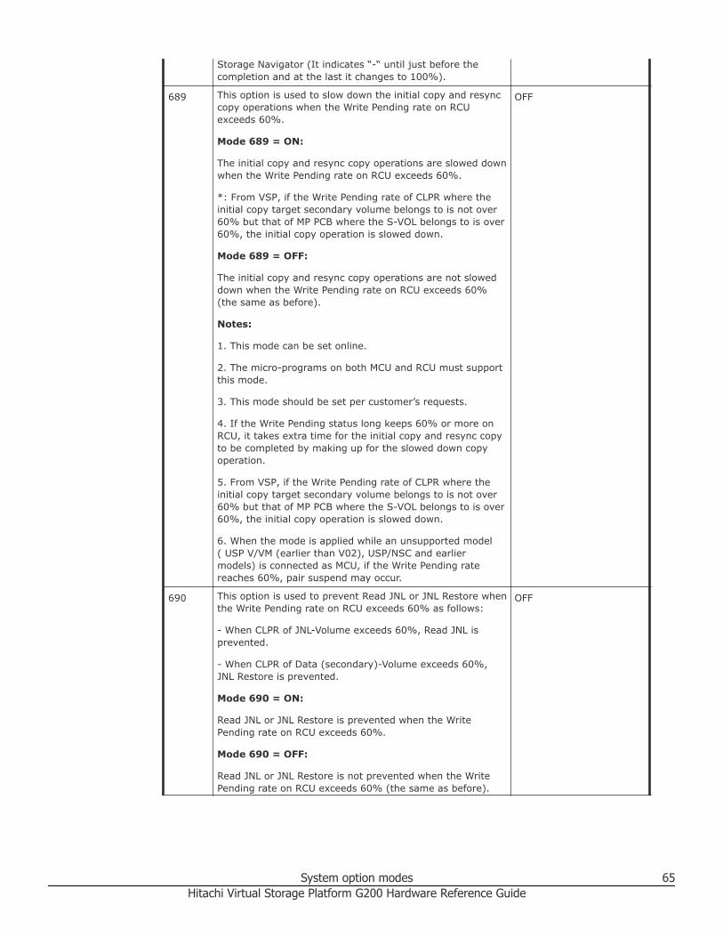
Storage Navigator (It indicates “-“ until just before thecompletion and at the last it changes to 100%).
689 This option is used to slow down the initial copy and resynccopy operations when the Write Pending rate on RCUexceeds 60%.
Mode 689 = ON:
The initial copy and resync copy operations are slowed downwhen the Write Pending rate on RCU exceeds 60%.
*: From VSP, if the Write Pending rate of CLPR where theinitial copy target secondary volume belongs to is not over60% but that of MP PCB where the S-VOL belongs to is over60%, the initial copy operation is slowed down.
Mode 689 = OFF:
The initial copy and resync copy operations are not sloweddown when the Write Pending rate on RCU exceeds 60%(the same as before).
Notes:
1. This mode can be set online.
2. The micro-programs on both MCU and RCU must supportthis mode.
3. This mode should be set per customer’s requests.
4. If the Write Pending status long keeps 60% or more onRCU, it takes extra time for the initial copy and resync copyto be completed by making up for the slowed down copyoperation.
5. From VSP, if the Write Pending rate of CLPR where theinitial copy target secondary volume belongs to is not over60% but that of MP PCB where the S-VOL belongs to is over60%, the initial copy operation is slowed down.
6. When the mode is applied while an unsupported model( USP V/VM (earlier than V02), USP/NSC and earliermodels) is connected as MCU, if the Write Pending ratereaches 60%, pair suspend may occur.
OFF
690 This option is used to prevent Read JNL or JNL Restore whenthe Write Pending rate on RCU exceeds 60% as follows:
- When CLPR of JNL-Volume exceeds 60%, Read JNL isprevented.
- When CLPR of Data (secondary)-Volume exceeds 60%,JNL Restore is prevented.
Mode 690 = ON:
Read JNL or JNL Restore is prevented when the WritePending rate on RCU exceeds 60%.
Mode 690 = OFF:
Read JNL or JNL Restore is not prevented when the WritePending rate on RCU exceeds 60% (the same as before).
OFF
System option modes 65Hitachi Virtual Storage Platform G200 Hardware Reference Guide

Notes:
1. This mode can be set online.
2. This mode should be set per customer’s requests.
3. If the Write Pending status long keeps 60% or more onRCU, it takes extra time for the initial copy to be completedby making up for the prevented copy operation.
4. If the Write Pending status long keeps 60% or more onRCU, the pair status may become Suspend due to the JNL-Vol being full.
5. When RAID 500 is used on P-VOL side, the mode cannotbe used. If the mode is set to ON, SSB=8E08 on P- VOLside and SSB=C8D1 on S-VOL side may frequently beoutput.
696 This mode is available to enable or disable the QoS function.
Mode 696 = ON:
QoS is enabled. (In accordance with the Share value set toSM, I/Os are scheduled. The Share value setting fromRMLIB is accepted.)
Mode 696 = OFF:
QoS is disabled. (The Share value set to SM is cleared. I/Oscheduling is stopped. The Share value setting from host isrejected.)
Note:
1. Set this mode to ON when you want to enable the QoSfunction.
OFF
701 This option is used to issue the Read command at the LUdiscovery operation using UVM.
Mode 701 = ON:
The Read command is issued at the LU discovery operation.
Mode 701 = OFF:
The Read command is not issued at the LU discoveryoperation.
Notes:
1. When the external storage is USP/NSC and the OpenLDEV Guard attribute (VMA) is defined on an externaldevice, set the mode to ON.
2. When this option is set to ON, it takes longer time tocomplete the LU discovery. The amount of time depends onexternal storages.
3. With this system option OFF, if searching for externaldevices with VMA set, the VMA information cannot be read.
4. When the mode is set to ON while the followingconditions are met, the external volume is blocked.
OFF
66 System option modesHitachi Virtual Storage Platform G200 Hardware Reference Guide
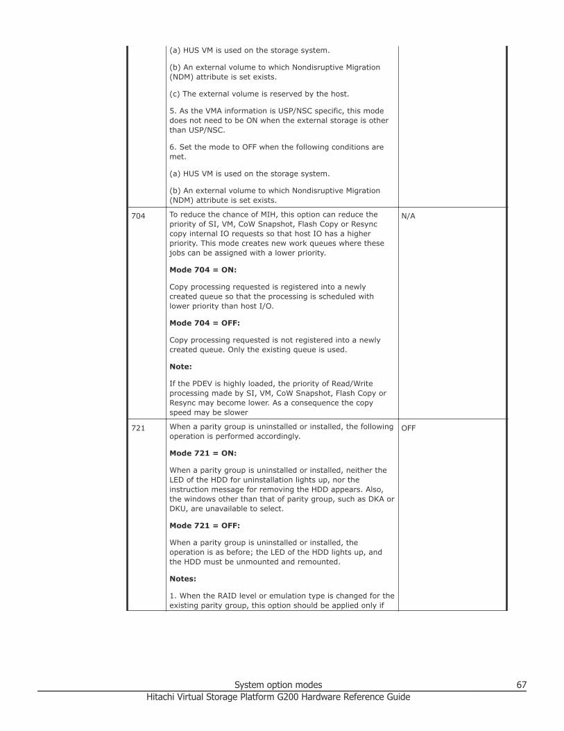
(a) HUS VM is used on the storage system.
(b) An external volume to which Nondisruptive Migration(NDM) attribute is set exists.
(c) The external volume is reserved by the host.
5. As the VMA information is USP/NSC specific, this modedoes not need to be ON when the external storage is otherthan USP/NSC.
6. Set the mode to OFF when the following conditions aremet.
(a) HUS VM is used on the storage system.
(b) An external volume to which Nondisruptive Migration(NDM) attribute is set exists.
704 To reduce the chance of MIH, this option can reduce thepriority of SI, VM, CoW Snapshot, Flash Copy or Resynccopy internal IO requests so that host IO has a higherpriority. This mode creates new work queues where thesejobs can be assigned with a lower priority.
Mode 704 = ON:
Copy processing requested is registered into a newlycreated queue so that the processing is scheduled withlower priority than host I/O.
Mode 704 = OFF:
Copy processing requested is not registered into a newlycreated queue. Only the existing queue is used.
Note:
If the PDEV is highly loaded, the priority of Read/Writeprocessing made by SI, VM, CoW Snapshot, Flash Copy orResync may become lower. As a consequence the copyspeed may be slower
N/A
721 When a parity group is uninstalled or installed, the followingoperation is performed accordingly.
Mode 721 = ON:
When a parity group is uninstalled or installed, neither theLED of the HDD for uninstallation lights up, nor theinstruction message for removing the HDD appears. Also,the windows other than that of parity group, such as DKA orDKU, are unavailable to select.
Mode 721 = OFF:
When a parity group is uninstalled or installed, theoperation is as before; the LED of the HDD lights up, andthe HDD must be unmounted and remounted.
Notes:
1. When the RAID level or emulation type is changed for theexisting parity group, this option should be applied only if
OFF
System option modes 67Hitachi Virtual Storage Platform G200 Hardware Reference Guide

the HDD mounted position remains the same at the time ofthe parity group uninstallation or installation.
2. After the operation using this option is completed, themode must be set back to Off; otherwise, the LED of theHDD to be removed will not light up at subsequent paritygroup uninstalling operations
725 This option determines an action when Not Ready isreturned from the external volume.
Mode 725 = ON:
When Not Ready is returned, the external path is blockedand the path status can be automatically recovered (NotReady blockade). Note that the two behaviors, automaticrecovery and blockade, may be repeated.
From version 60-05-06-00/00, the following is added.
For the device of Not Ready blockade, the Device HealthCheck is executed after 30 seconds.
Mode 725 = OFF:
When Not Ready is returned 3 times in 3 minutes, the pathis blocked and the path status cannot be automaticallyrecovered (Response error blockade).
Notes:
1. For HUS VM:
(1) Applying this System Option Mode is prohibited whenUSP V/VM is used as an external subsystem and its externalvolume is DP-VOL.
(2) Applying this System Option Mode is recommendedwhen the above condition (1) is not met and SUN storage isused as an external storage.
(3) Applying this System Option Mode is recommendedwhen the above condition (1) is not met and EMC CX series,VNX series, or Fujitsu Fibre CAT CX series is used as anexternal storage.
(4) Applying this System Option Mode is recommended ifthe above condition (1) is not met and a maintenanceoperation such as firmware update causing controller rebootis executed on the external storage side while a storagesystem other than Hitachi product is used as an externalsubsystem.
2. While USP V/VM is used as an external subsystem and itsvolume is DP-VOL, if some Pool-VOLs constituting the DP-VOL are blocked, a phenomenon of external path blockadeand recovery occurs repeatedly.
3. In the case that a virtual volume mapped by UVM is setto pool-VOL and used as DP-VOL in local subsystem, thisSystem Option Mode can be applied without problem.
OFF
729 To set the Protect attribute for the target DP-VOL using theDRU, when any Write operation is requested to the area
OFF
68 System option modesHitachi Virtual Storage Platform G200 Hardware Reference Guide

where the page allocation is not provided at a time whenthe HDP Pool is full.
Mode 729 = ON:
To set the Protect attribute for the target DP-VOL using theDRU, when any Write operation is requested to the areawhere the page allocation is not provided at a time whenthe HDP Pool is full. (Not to set in the case of Readrequest).
Mode 729 = OFF:
Not to set the Protect attribute for the target DP-VOL usingthe DRU, when any Write operation is requested to the areawhere the page allocation is not provided at a time whenHDP Pool is full.
Notes:
1. This System Option Mode is applied when;
-The threshold of Pool is high (e.g., 95%) and the Pool maybe full.
-DP V-VOL uses file system.
-Data Retention Utility is installed.
2. Since the Protect attribute is set for V-VOL, the Readoperation cannot be allowed as well.
3. When the Data Retention Utility is not installed, thedesired effect is not achieved.
4. Protect attribute can be released from the Data Retentionwindow of Storage Navigator after releasing the full statusof the Pool by adding a Pool-VOL.
5. With VSP Gx00/Fx00 V01+1 and later, do not change themode setting but use the virtual volume protection functionwhen the pool is full to change the setting.
6. With VSP Gx00/Fx00 V01+1 and later, when HM O63 or73 is set to ON, the setting of the HMO is prioritized overthe System Option Mode 729 setting so that the behaviorremains as that of setting the mode to OFF even when theSystem Option Mode is set to ON.
733 This option enables to suspend Volume Migration or QuickRestore operation during LDEV-related maintenance.
USP V/VM:
Mode 733 = ON:
Volume Migration or Quick Restore operation during LDEV-related maintenance is suspended.
Mode 733 = OFF:
Volume Migration or Quick Restore operation during LDEV-related maintenance is not suspended.
VSP and later models, HUS VM and later models:
OFF
System option modes 69Hitachi Virtual Storage Platform G200 Hardware Reference Guide

Mode 733 = ON:
Volume Migration or Quick Restore operation during LDEV-related maintenance is not suspended
Mode 733 = OFF:
Volume Migration or Quick Restore operation during LDEV-related maintenance is suspended.
Notes:
1. (USP V/VM) This option is recommended as functionalimprovement to avoid maintenance failures. In some casesof a failure in LDEV-related maintenance without setting theoption, Storage Navigator operations may be unavailable.
2. (USP V/VM) There is the potential for LDEV-relatedmaintenance activities to fail when Volume Migration andQuick Restore is active without setting the option.
3. Note that behavior when the mode is set to ON and OFFis reversed between USP V/VM and VSP and later/HUS VMand later.
4. (USP V/VM) This option should be applied when VolumeMigration or Quick Restore operation can be suspendedduring LDEV-related maintenance.
5. (USP V/VM) If virtual volume capacity expansionoperation conflicts with Volume Migration or Quick Restoreoperation, the virtual volume capacity expansion operationmay fail.
6. (VSP and later/HUS VM and later) This mode should beapplied to perform Volume Migration or Quick Restoreduring maintenance operation.
7. (VSP and later/HUS VM and later) Set mode 733 to ON ifyou want to prioritize the Volume Migration or Quick Restoreoperation over maintenance activities. In this case,maintenance activities may fail when the Volume Migrationor Quick Restore operation works during the maintenanceactivities.
8. (VSP and later/HUS VM and later) An LDEV-relatedmaintenance operation such as LDEV installation/removalmay fail when Volume Migration or Quick Restore takesplace.
734 When exceeding the pool threshold, the SIM is reported asfollows.
Mode 734 = ON:
A SIM is reported at the time when the pool usage rateexceeds the pool threshold (warning, system, or depletion).Once the pool usage rate falls below the pool threshold, andthen exceeds again, the SIM is reported again. If the poolusage rate continues to exceed the warning threshold andthe depletion threshold, the SIM (SIM-RC625000) isrepeatedly reported every eight (8) hours until the poolusage rate falls below the depletion threshold.
OFF
70 System option modesHitachi Virtual Storage Platform G200 Hardware Reference Guide

Mode 734 = OFF:
A SIM is reported at the time when the pool usage rateexceeds the pool threshold (warning, system, or depletion).Once the pool usage rate falls below the pool threshold, andthen exceeds again, the SIM is reported again. The SIM isnot reported while the pool usage rate continues to exceedthe warning threshold and the depletion threshold.
Notes:
1. This option is turned ON to prevent the Write I/Ooperation from being unavailable due to pool full.
2. If the pool threshold exceeding SIM occurs frequently,other SIMs may not be reported.
3. Though turning on this option can increase the warningeffect, if measures such as adding a pool fail to be done intime so that the pool becomes full, system option mode 729can be used to prevent file systems from being destroyed.
4. Turning on system option mode 741 can provide the SIMreport to not only the users but also the service personnel.
741 The option enables to switch over whether to report thefollowing SIM for users to the service personnel.
SIM-RC 625000 (DP Pool usage rate continues to exceed thethreshold)
Mode 741 = ON:
SIM is reported to the service personnel
Mode 741 = OFF:
SIM is not reported to the service personnel
Notes:
1. This option is set to ON to have SIM for users reported tothe service personnel,
- for the system where SNMP and E-mail notification are notset.
- if Storage Navigator isn’t periodically activated.
2. When Mode 734 is turned OFF, SIM-RC625000 is notreported; accordingly the SIM is not reported to the servicepersonnel even though this option is ON.
OFF
745 This option enables to change the area where theinformation is obtained as the Characteristic1 item fromSYMMETRIX.
Mode 745 = ON:
(1) The area where the information is obtained as theCharacteristic1 item from SYMMETRIX is changed.
(2) When CheckPaths or Device Health Check (1/hour) isperformed, the information of an already-mapped externalvolume is updated to the one after change.
OFF
System option modes 71Hitachi Virtual Storage Platform G200 Hardware Reference Guide
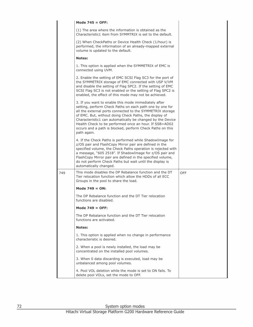
Mode 745 = OFF:
(1) The area where the information is obtained as theCharacteristic1 item from SYMMTRIX is set to the default.
(2) When CheckPaths or Device Health Check (1/hour) isperformed, the information of an already-mapped externalvolume is updated to the default.
Notes:
1. This option is applied when the SYMMETRIX of EMC isconnected using UVM.
2. Enable the setting of EMC SCSI Flag SC3 for the port ofthe SYMMETRIX storage of EMC connected with USP V/VMand disable the setting of Flag SPC2. If the setting of EMCSCSI Flag SC3 is not enabled or the setting of Flag SPC2 isenabled, the effect of this mode may not be achieved.
3. If you want to enable this mode immediately aftersetting, perform Check Paths on each path one by one forall the external ports connected to the SYMMETRIX storageof EMC. But, without doing Check Paths, the display ofCharacteristic1 can automatically be changed by the DeviceHealth Check to be performed once an hour. If SSB=AD02occurs and a path is blocked, perform Check Paths on thispath again.
4. If the Check Paths is performed while ShadowImage forz/OS pair and FlashCopy Mirror pair are defined in thespecified volume, the Check Paths operation is rejected witha message, “605 2518”. If ShadowImage for z/OS pair andFlashCopy Mirror pair are defined in the specified volume,do not perform Check Paths but wait until the display isautomatically changed.
749 This mode disables the DP Rebalance function and the DTTier relocation function which allow the HDDs of all ECCGroups in the pool to share the load.
Mode 749 = ON:
The DP Rebalance function and the DT Tier relocationfunctions are disabled.
Mode 749 = OFF:
The DP Rebalance function and the DT Tier relocationfunctions are activated.
Notes:
1. This option is applied when no change in performancecharacteristic is desired.
2. When a pool is newly installed, the load may beconcentrated on the installed pool volumes.
3. When 0 data discarding is executed, load may beunbalanced among pool volumes.
4. Pool VOL deletion while the mode is set to ON fails. Todelete pool VOLs, set the mode to OFF.
OFF
72 System option modesHitachi Virtual Storage Platform G200 Hardware Reference Guide

757 Setting this mode to ON or OFF to disable or enableoutputting In-band audit logs.
Mode 757 = ON:
In-band audit log is not output.
Mode 757 = OFF:
In-band audit log is output.
Notes:
(1) Mode 757 applies to the sites where outputting the In-band audit logs is not needed.
(2) When this option is set to ON,
- There is no access to SM for the In-band audit logs, whichcan avoid the corresponding performance degradation.
- SM is not used for the In-band audit logs.
(3) If outputting the In-band audit log is desired, set thismode to OFF.
OFF
784 This mode can reduce the MIH watch time of RI/O for a TCSync or GAD pair internally so that update I/Os cancontinue by using an alternate path without time-outoccurrence in the environment where Open host time-outtime is short (15 seconds or less). The mode is effective atinitial pair creation or Resync operation for TC Sync or GAD.(Not effective by just setting this mode to ON)
The mode is applied to TC Sync (83-01-01-x0/00 andhigher) and GAD (83-01-21-x0/00 and higher).
Mode 784 = ON:
The MIH time of RIO is internally reduced so that, eventhough a path failure occurs between DKCs in theenvironment where host MIH time is set to 15 seconds,update I/Os can be processed by using an alternate pathpromptly, lowering the possibility of host MIH occurrence.
Mode 784 = OFF:
The operation is processed in accordance with the TC Syncspecification.
Notes:
(1) The mode is applied to the environment where OPENhost time-out time is set to 15 seconds or less.
(2) The mode is applied to reduce RI/O MIH time to 5seconds.
(3) This function is available for all the TC Sync and GADpairs on the subsystem, unable to specify the pairs that areusing this function or not.
(4) To apply the mode to TC Sync, both MCU and RCU mustbe HUS VM and micro-program must be the support version
OFF
System option modes 73Hitachi Virtual Storage Platform G200 Hardware Reference Guide

on both sides. If either one of MCU or RCU is USP V/VM, thefunction cannot be applied.
(5) For a TC Sync or GAD pair with the mode effective (RI/OMIH time is 5 seconds), the setting of RI/O MIH time madeat RCU registration (default is 15 seconds, which can bechanged within range from 10 to 100 seconds) is invalid.However, RI/O MIH time displayed on Storage Navigator andCCI is not “5 seconds” but is what set at RI/O registration.
(6) If a failure occurs on the switched path between DKCs,Open server time-out may occur.
(7) If an MP to which the path between DKCs belongs isoverloaded, switching to an alternate path delays and time-out may occur.
(8) If an RI/O retry occurs due to other factors than RI/OMIH (5 sec), such as a check condition report issued fromRCU to MCU, the RI/O retry is performed on the same pathinstead of an alternate path. If a response delay to the RI/Ooccurs constantly on this path due to path failure or linkdelay, time-out may occur due to response timeaccumulation for each RI/O retried within 5 seconds.
(9) Even though the mode is set to ON, if Open host time-out time is set to 10 seconds or less, time-out may occurdue to a path failure between DKCs.
(10) Operation commands are not available for promptlyswitching to an alternate path.
(11) The mode works for the pair for which initial paircreation or Resync operation is executed.
(12) Micro-program downgrade to an unsupported versioncannot be executed unless all the TC Sync pairs aresuspended or deleted.
(13) See System Option Mode 784 sheet for operationalspecifications in each combination of MCU and RCU of TC.
(14) For GAD pairs, the mode is effective if the microcode isin a version that supports GAD.
(15) The mode does not support paths between DKCs usingiSCSI in VSP Gx00/Fx00. (Configuration where DKC paths ofFibre and iSCSI coexist is not supported.)
803 While a DP pool VOL is blocked, if a read or write I/O isissued to the blocked pool VOL, this mode can enable theProtect attribute of DRU for the target DP-VOL.
Mode 803 = ON:
While a DP pool VOL is blocked, if a read or write I/O isissued to the blocked pool VOL, the DRU attribute is set toProtect.
Mode 803 = OFF:
While a DP pool VOL is blocked, if a read or write I/O isissued to the blocked pool VOL, the DRU attribute is not setto Protect.
OFF
74 System option modesHitachi Virtual Storage Platform G200 Hardware Reference Guide

See the System Option Mode 729 and 803 sheet for moredetails.
Notes:
1. This mode is applied when
- a file system using DP pool VOLs is used.
- Data Retention Utility is installed.
2. Because the DRU attribute is set to Protect for the V-VOL,a read I/O is also disabled.
3. If Data Retention Utility is not installed, the expectedeffect cannot be achieved.
4. The Protect attribute of DRU for the HDP V-VOL can bereleased on the Data Retention window of Storage Navigatorafter recovering the blocked pool VOL.
5. With HM800 V01+1 and later, do not change the modesetting but use the virtual volume protection function whenthe pool volume is blocked to change the setting.
855 By switching the mode to ON/OFF when ShadowImage isused with System Option Mode 467 set to ON, copyprocessing is continued or stopped as follows.
Mode 855 = ON:
When the amount of dirty data is within the range from58% to 63%, the next copy processing is continued afterthe dirty data created in the previous copy is cleared toprevent the amount of dirty data from increasing (copy afterdestaging). If the amount of dirty data exceeds 63%, thecopy processing is stopped.
Mode 855 = OFF:
The copy processing is stopped when the amount of dirtydata is over 60%.
For details, see the System Option Mode 855 sheet.
Notes:
1. This mode is applied when all the following conditions aremet.
- ShadowImage is used with System Option Mode 467 set toON.
- Write pending rate of an MP blade that has LDEVownership of the copy target is high.
- Usage rate of a parity group to which the copy targetLDEV belongs is low.
- ShadowImage copy progress is delayed.
2. This mode is available only when System Option Mode467 is set to ON.
OFF
System option modes 75Hitachi Virtual Storage Platform G200 Hardware Reference Guide

3. If workload of the copy target parity group is high, thecopy processing may not be improved even if this mode isset to ON.
857 This option enables or disables to limit the cache allocationcapacity per MPB (VSP / VSP G1000) or MPU (HUS VM) towithin the prescribed capacity (*) except for CacheResidency.
*: 128 GB (VSP/HUS VM), 256 GB (VSP G1000).
Mode 857 = ON:
The cache allocation capacity is limited to within theprescribed capacity.
Mode 857 = OFF:
The cache allocation capacity is not limited to within theprescribed capacity.
Notes:
(1) This mode is applied to stabilize the performance bypreventing paging of PM control information from occurring.For details, refer to the section of Virtual Partition Managerin the guideline.
(2) The cache hit rate may decrease.
(3) The cache allocation capacity per MPB/MPU is limited towithin the prescribed capacity.
OFF
867 All-page reclamation (discarding all mapping informationbetween DP pool and DP volumes) is executed in DP-VOLLDEV format. This new method is enabled or disabled bysetting the mode to ON or OFF.
(Version 83-04-01-x0/00 or later) Mode 867 = ON:
LDEV format of the DP-VOL is performed with pagereclamation.
(Version 83-03-xx or earlier) Mode 867 = OFF:
LDEV format of the HDP-VOL is performed with 0 datawriting.
Notes:
1. The mode is applied from factory shipment.
2. Do not change the setting of the mode during DP-VOLformat.
3. If the setting of the mode is changed during DP-VOLformat, the change is not reflected to the format of the DP-VOL being executed but the format continues in the samemethod.
ON
896 The mode enables or disables the background formatfunction performed on an unformatted area of a DP/DT/TI*1pool.
*1: The background format function for a TI pool is onlyavailable for V01+1 (73-01-31-00/00) or higher.
ON
76 System option modesHitachi Virtual Storage Platform G200 Hardware Reference Guide

* For the information of operating conditions, refer toProvisioning Guide for Open Systems.
Mode 896 = ON:
The background format function is disabled.
Mode 896 = OFF:
The background format function is enabled.
Notes:
1. <HUS VM> The mode is applied when a customerrequires disabling the background format for a DP/DT/TI*1pool due to a concern of performance degradation of otherfunctions in an environment where a DP-VOL is used byother functions.
2. When the background format function is enabled,because up to 42MB/s of ECCG performance is used, localcopy performance may degrade by about 10%. Therefore,confirm whether the 10% performance degradation isacceptable or not before enabling the function.
3. When a Dynamic Provisioning VOL on an external storagesystem, which is used as an external VOL, is used as a poolVOL, if the external pool on the external storage sidebecomes full due to the background format, the externalVOL may be blocked.
If the external pool capacity is smaller than the externalVOL capacity (Dynamic Provisioning VOL of external storagesystem), do not enable the background format function.
4. If the background format function is disabled by changingthe mode setting, the format progress is initialized and theentire area become unformatted.
897 By the combination of System Option Mode 897 and 898setting, the expansion width of Tier Range upper I/O value(IOPH) can be changed as follows.
Mode 897 = ON:
System Option Mode 898 is OFF: 110%+0IO
System Option Mode 898 is ON: 110%+2IO
Mode 897 = OFF (Default)
System Option Mode 898 is OFF: 110%+5IO (Default)
System Option Mode 898 is ON: 110%+1IO
By setting the System Option Modes to ON to lower theupper limit for each tier, the gray zone between other tiersbecomes narrow and the frequency of page allocationincreases.
Notes:
1. Apply the mode when the usage of upper tier is low andthat of lower tier is high.
OFF
System option modes 77Hitachi Virtual Storage Platform G200 Hardware Reference Guide
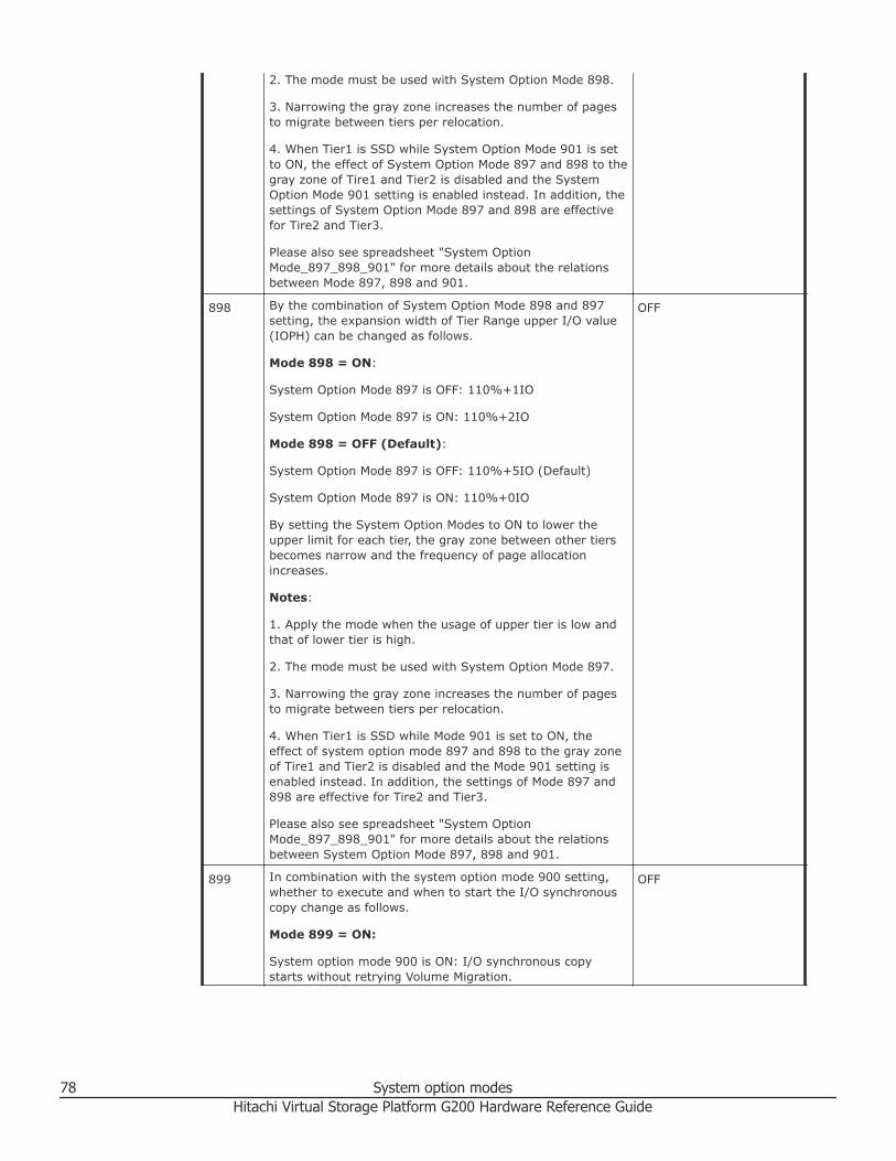
2. The mode must be used with System Option Mode 898.
3. Narrowing the gray zone increases the number of pagesto migrate between tiers per relocation.
4. When Tier1 is SSD while System Option Mode 901 is setto ON, the effect of System Option Mode 897 and 898 to thegray zone of Tire1 and Tier2 is disabled and the SystemOption Mode 901 setting is enabled instead. In addition, thesettings of System Option Mode 897 and 898 are effectivefor Tire2 and Tier3.
Please also see spreadsheet "System OptionMode_897_898_901" for more details about the relationsbetween Mode 897, 898 and 901.
898 By the combination of System Option Mode 898 and 897setting, the expansion width of Tier Range upper I/O value(IOPH) can be changed as follows.
Mode 898 = ON:
System Option Mode 897 is OFF: 110%+1IO
System Option Mode 897 is ON: 110%+2IO
Mode 898 = OFF (Default):
System Option Mode 897 is OFF: 110%+5IO (Default)
System Option Mode 897 is ON: 110%+0IO
By setting the System Option Modes to ON to lower theupper limit for each tier, the gray zone between other tiersbecomes narrow and the frequency of page allocationincreases.
Notes:
1. Apply the mode when the usage of upper tier is low andthat of lower tier is high.
2. The mode must be used with System Option Mode 897.
3. Narrowing the gray zone increases the number of pagesto migrate between tiers per relocation.
4. When Tier1 is SSD while Mode 901 is set to ON, theeffect of system option mode 897 and 898 to the gray zoneof Tire1 and Tier2 is disabled and the Mode 901 setting isenabled instead. In addition, the settings of Mode 897 and898 are effective for Tire2 and Tier3.
Please also see spreadsheet "System OptionMode_897_898_901" for more details about the relationsbetween System Option Mode 897, 898 and 901.
OFF
899 In combination with the system option mode 900 setting,whether to execute and when to start the I/O synchronouscopy change as follows.
Mode 899 = ON:
System option mode 900 is ON: I/O synchronous copystarts without retrying Volume Migration.
OFF
78 System option modesHitachi Virtual Storage Platform G200 Hardware Reference Guide

System option mode 900 is OFF: I/O synchronous copystarts when the threshold of Volume Migration retry isexceeded. (Recommended).
Mode 899 = OFF:
System option mode 900 is ON: I/O synchronous copystarts when the number of retries reaches half of thethreshold of Volume Migration retry.
System option mode 900 is OFF: Volume Migration is retiredand I/O synchronous copy is not executed.
Notes:
1. This mode is applied when improvement of VolumeMigration success rate is desired under the condition thatthere are many updates to a migration source volume ofVolume Migration.
2. During I/O synchronous copy, host I/O performancedegrades.
900 In combination with system option mode 899 setting,whether to execute and when to start the I/O synchronouscopy change as follows.
Mode 900 = ON:
System option mode 899 is ON: I/O synchronous copystarts without retrying Volume Migration.
System option mode 899 is OFF: I/O synchronous copystarts when the number of retries reaches half of thethreshold of Volume Migration retry.
Mode 900 = OFF:
System option mode 899 is ON: I/O synchronous copystarts when the threshold of Volume Migration retry isexceeded. (Recommended)
System option mode 899 is OFF: Volume Migration is retiredand I/O synchronous copy is not executed.
Notes:
1. This mode is applied when improvement of VolumeMigration success rate is desired under the condition thatthere are many updates to a migration source volume ofVolume Migration.
2. During I/O synchronous copy, host I/O performancedegrades.
OFF
901 By setting the mode to ON or OFF, the page allocationmethod of Tier Level ALL when the drive type of tier1 is SSDchanges as follows.
Mode 901 = ON:
For tier1 (drive type is SSD), pages are allocated until thecapacity reaches the limit.
OFF
System option modes 79Hitachi Virtual Storage Platform G200 Hardware Reference Guide

(Without consideration of exceeding performance limitation,allocation is done from highly loaded pages until reachingthe capacity limit.
When the capacity of the tier1 reaches the threshold value,the minimum value of the tier range is set to the startingvalue of the lower IOPH zone, and the maximum value ofthe lower tier range is set to the boundary value.
Mode 901 = OFF (default):
For tier1 (drive type is SSD), page allocation is performedbased on performance potential limitation.
(With consideration of exceeding performance limitation,allocation is done from highly loaded pages but at the pointwhen the performance limitation is reached, pages are notallocated any more even there is free space)
When the capacity of the tier1 reaches the threshold value,the minimum value of the tier range is set to the boundaryvalue, and the maximum value of the lower tier range is setto a value of boundary value x 110% + 5 [IOPH].
Notes:
1. This mode is applied when pages with the maximumcapacity need to be allocated to tier1 (drive type is SSD)with DT or DTz.
2. When Tier1 is SSD while System Option Mode 901 is setto ON, the effect of System Option Mode 897 and 898 to thegray zone of Tire1 and Tier2 is disabled and the SystemOption Mode 901 setting is enabled instead. In addition, thesettings of System Option Mode 897 and 898 are effectivefor Tire2 and Tier3.
3. The following is recommended when applying SystemOption Mode 901.
The actual I/O value (total number of I/Os of all tieringpolicies) < the performance potential value of Tier 1*1 x 0.6
*1: The performance potential value of Tier 1 displayed onMonitor information by using Dx-ray.
Please also see spreadsheet "System Option Mode897_898_901" for more details about the relations betweenSystem Option Mode 897, 898 and 901.
904 By setting the mode to ON or OFF, the number of pages tobe migrated per unit time at tier relocation is changed.
Mode 904 = ON:
The number of pages to be migrated at tier relocation is setto up to one page per second.
Mode 904 = OFF:
No restriction on the number of pages to be migrated at tierrelocation (existing specification).
Notes:
OFF
80 System option modesHitachi Virtual Storage Platform G200 Hardware Reference Guide
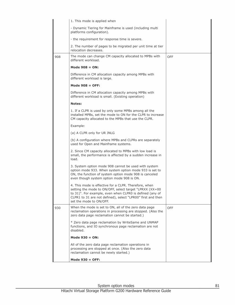
1. This mode is applied when
- Dynamic Tiering for Mainframe is used (including multiplatforms configuration).
- the requirement for response time is severe.
2. The number of pages to be migrated per unit time at tierrelocation decreases.
908 The mode can change CM capacity allocated to MPBs withdifferent workload.
Mode 908 = ON:
Difference in CM allocation capacity among MPBs withdifferent workload is large.
Mode 908 = OFF:
Difference in CM allocation capacity among MPBs withdifferent workload is small. (Existing operation)
Notes:
1. If a CLPR is used by only some MPBs among all theinstalled MPBs, set the mode to ON for the CLPR to increaseCM capacity allocated to the MPBs that use the CLPR.
Example:
(a) A CLPR only for UR JNLG
(b) A configuration where MPBs and CLPRs are separatelyused for Open and Mainframe systems.
2. Since CM capacity allocated to MPBs with low load issmall, the performance is affected by a sudden increase inload.
3. System option mode 908 cannot be used with systemoption mode 933. When system option mode 933 is set toON, the function of system option mode 908 is canceledeven though system option mode 908 is ON.
4. This mode is effective for a CLPR. Therefore, whensetting the mode to ON/OFF, select target "LPRXX (XX=00to 31)". For example, even when CLPR0 is defined (any ofCLPR1 to 31 are not defined), select “LPR00” first and thenset the mode to ON/OFF.
OFF
930 When the mode is set to ON, all of the zero data pagereclamation operations in processing are stopped. (Also thezero data page reclamation cannot be started.)
* Zero data page reclamation by WriteSame and UNMAPfunctions, and IO synchronous page reclamation are notdisabled.
Mode 930 = ON:
All of the zero data page reclamation operations inprocessing are stopped at once. (Also the zero datareclamation cannot be newly started.)
Mode 930 = OFF:
OFF
System option modes 81Hitachi Virtual Storage Platform G200 Hardware Reference Guide

The zero data page reclamation is performed.
See the system option mode 930 sheet for relationship withsystem option mode 755.
Notes:
(1) The mode is applied when stopping or disabling zerodata page reclamation by user request is required.
(2) When the mode is set to ON, the zero data pagereclamation does not work at all.
* Zero data page reclamation by Write Same and UNMAP,and IO synchronous page reclamation can work.
(3) When downgrading micro-program to a version thatdoes not support the mode while the mode is set to ON, setthe mode to OFF after the downgrade.
* Because the zero data page reclamation does not work atall while the mode is set to ON.
937 By setting the mode to ON, DT monitoring data is collectedeven if the pool is a DP pool.
Mode 937 = ON:
DT monitoring data is collected even if the pool is a DP pool.
Only Manual execution mode and Period mode aresupported.
Mode 937 = OFF:
DT monitoring data is not collected if the pool is a DP pool
Notes:
1. The mode is applied when DT monitoring data collectionis required in DP environment.
2. When DT is already used, do not set the mode to ON.
3. For DT monitoring data collection, shared memory for DTmust be installed. For details, see the system option mode937 sheet.
4. If monitoring data collection is performed without sharedmemory for DT installed, an error is reported and themonitoring data collection fails.
5. Before removing the shared memory for DT, set the modeto OFF and wait for 30 minutes.
6. Tier relocation with monitoring data collected when themode is set to ON is disabled.
7. When DP is converted into DT (after purchase of PPlicense), the collected monitoring data is discarded.
8. Before downgrading the micro-program to anunsupported version, set system option mode 937 to OFFand wait for at least 30 minutes.
OFF
82 System option modesHitachi Virtual Storage Platform G200 Hardware Reference Guide

1021 The mode can enable or disable the auto-recovery forexternal volumes of an EMC storage system.
Mode 0121 = ON:
An external volume that is blocked due to Not Ready statuscan be recovered automatically regardless of the type ofexternal storage system.
Mode 1021 = OFF (default):
An external volume that is blocked due to Not Ready statusmight not be recovered automatically depending on the typeof external storage system.
Notes:
(1) The mode is applied when the auto-recovery of externalvolumes that are blocked due to Not Ready status is desiredin UVM connection using an ECM storage system as anexternal storage system.
(2) When the mode is set to ON and the connected externalstorage system is not in stable status (such as failure andrecovery from failure), a blockage due to Not Ready statusand auto-recovery may occur repeatedly.
OFF
1070 The mode changes the processing for a group operationwith GAD CTG.
Mode 1070 = ON:
The status change of all pairs in a CTG is performed for 50msec.
Mode 1070 = OFF (default):
The status change of all pairs in a CTG is performed for 1msec.
Notes:
(1) The mode is applied when reducing the time to completestatus change of all pairs in a CTG at a group operation(suspension and resync operation) with the GAD CTGfunction. In a system configuration where host I/Operformance is prioritized, do not use the mode becausesetting the mode may affect the host I/O performance.
(2)The MP usage rate increases during status change of allpairs in a CTG. For approximate percentage increase in MPusage rate, see sheet "System Option Mode 1070".
OFF
1093 This mode is used to disable background unmap duringmicrocode downgrade from a version that supports poolreduction rate correction to a version that does not supportthe function.
Mode 1093 = ON:
Background unmap cannot work.
Mode 1093 = OFF (default):
Background unmap can work.
OFF
System option modes 83Hitachi Virtual Storage Platform G200 Hardware Reference Guide
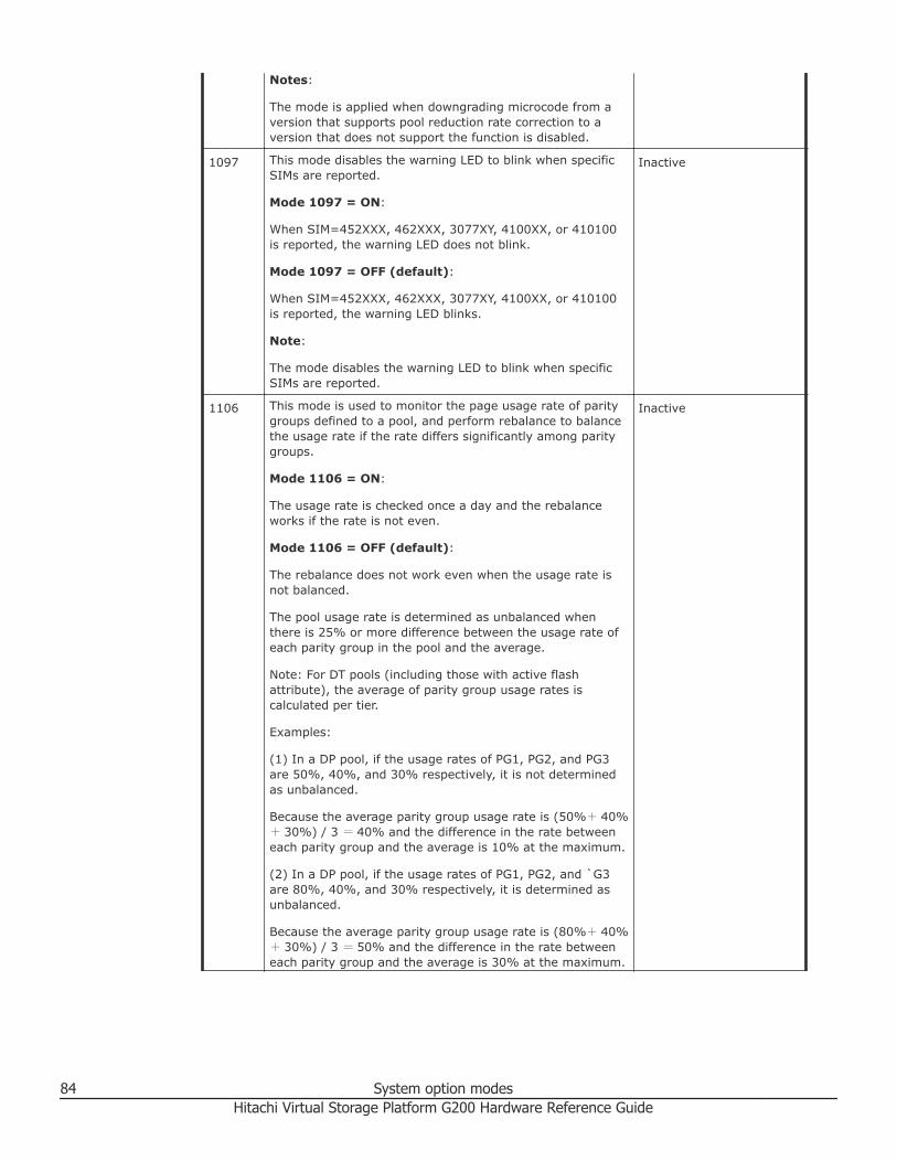
Notes:
The mode is applied when downgrading microcode from aversion that supports pool reduction rate correction to aversion that does not support the function is disabled.
1097 This mode disables the warning LED to blink when specificSIMs are reported.
Mode 1097 = ON:
When SIM=452XXX, 462XXX, 3077XY, 4100XX, or 410100is reported, the warning LED does not blink.
Mode 1097 = OFF (default):
When SIM=452XXX, 462XXX, 3077XY, 4100XX, or 410100is reported, the warning LED blinks.
Note:
The mode disables the warning LED to blink when specificSIMs are reported.
Inactive
1106 This mode is used to monitor the page usage rate of paritygroups defined to a pool, and perform rebalance to balancethe usage rate if the rate differs significantly among paritygroups.
Mode 1106 = ON:
The usage rate is checked once a day and the rebalanceworks if the rate is not even.
Mode 1106 = OFF (default):
The rebalance does not work even when the usage rate isnot balanced.
The pool usage rate is determined as unbalanced whenthere is 25% or more difference between the usage rate ofeach parity group in the pool and the average.
Note: For DT pools (including those with active flashattribute), the average of parity group usage rates iscalculated per tier.
Examples:
(1) In a DP pool, if the usage rates of PG1, PG2, and PG3are 50%, 40%, and 30% respectively, it is not determinedas unbalanced.
Because the average parity group usage rate is (50%+ 40%+ 30%) / 3 = 40% and the difference in the rate betweeneach parity group and the average is 10% at the maximum.
(2) In a DP pool, if the usage rates of PG1, PG2, and `G3are 80%, 40%, and 30% respectively, it is determined asunbalanced.
Because the average parity group usage rate is (80%+ 40%+ 30%) / 3 = 50% and the difference in the rate betweeneach parity group and the average is 30% at the maximum.
Inactive
84 System option modesHitachi Virtual Storage Platform G200 Hardware Reference Guide

(3) In a DT pool, if the usage rates of PG1, PG2, and PG3are 80% (SSD), 40% (SAS15K) and 30% (SAS15K), it isnot determined as unbalanced because:
- the average parity group usage rate of Tier1 is (80%) / 1= 80% and the difference in the rate between the paritygroup and the average is 0%.
- the average parity group usage rate of Tier2 is (40%+
30%) / 2 = 35% and the difference in the rate betweenthe parity group and the average is 5% at the maximum.
Note:
(1) The mode is applied when balancing the usage rate isrequired at a customer site where the usage rate is noteven.
System option modes 85Hitachi Virtual Storage Platform G200 Hardware Reference Guide

86 System option modesHitachi Virtual Storage Platform G200 Hardware Reference Guide

4Maintaining the storage system
Maintenance covers a broad spectrum of activity with the goal of keeping astorage system operational and available to all hosts. This chapter describestopics for performing storage system maintenance.
For more complex maintenance activities, contact customer support.
□ Storing the storage system
□ Using flash module drives
□ Powering off the storage system
□ Removing cables
Maintaining the storage system 87Hitachi Virtual Storage Platform G200 Hardware Reference Guide

Storing the storage systemIf the storage system does not receive power for more than six months, thebattery can become discharged and possibly damaged. To avoid thissituation, charge the battery for more than three hours at least once everysix months.
Note: Do not store the equipment in an environment with temperatures of104ºF (40ºC) or higher because battery life will be shortened.
Using flash module drivesObserve the following guidelines when handling the listed flash module drives(FMDs). The types of FMDs are equipped with a battery or capacitor.
Power up the flash module drives using power from the storage system for atleast 90 minutes every month. Failing to do so may render a flash moduledrive unusable and will abrogate replacement under the terms of thewarranty.
Model Name Drive type Battery Capacitor
DKC-F710I-1R6FM NFH1A-P1R6SS yes N/A
NFH1C-P1R6SS yes N/A
NFH1D-P1R6SS N/A Yes
DKC-F710I-3R2FM NFH1B-P3R2SS yes N/A
NFH1C-P3R2SS yes N/A
NFH1D-P3R2SS N/A yes
DKC-F810I-1R6FN NFHAE-Q1R6SS N/A yes
NFH1D-P1R6SS N/A yes
DKC-F810I-3R2FN NFHAE-Q3R2SS N/A yes
NFH1D-P3R2SS N/A yes
DKC-F810I-6R4FN NFHAE-Q6R4SS N/A yes
NFH1D-P6R4SS N/A yes
Guidelines for handling the FMDs
Follow the guidelines to avoid damaging the components when handlingFMDs.• Check the main edge connector of the drive for any damage, deformation,
dust or debris before installing.
88 Maintaining the storage systemHitachi Virtual Storage Platform G200 Hardware Reference Guide

• Check for floats or position gaps in the connector. Mark the identifiedlocation.
• To prevent any damages to the FMD, avoid touching the connector orhandling the ends of the FMD. Use both hands to hold the middle area ofthe FMD.
• Avoid installing or removing the FMD at an angled position.
Powering off the storage systemProcedure
1. Press the main switch for three seconds until the POWER LED blinks.2. Verify that the POWER LED on the front of the storage system changes
from green to amber.It can take from 25 minutes to 4 hours for the POWER LED to turn amber,depending on the configuration of the system (check after 33 minutes).
3. To stop the power supply from supplying power, remove the power cablesfrom the power supply units on the controller chassis and drive box.If the storage system is connected to a PDU, you can stop the powersupply by turning off the PDU breaker.
Note: If the storage system does not receive power for more thansix months, the battery can become discharged and possiblydamaged. To avoid this situation, charge the battery for more thanthree hours at least once every six months.
Removing cablesObserve the following instructions when removing cables form the storagesystem.
To remove a SAS cable, pull the tab of the SAS cable (1) to release the latchand remove the SAS cable (2).
Maintaining the storage system 89Hitachi Virtual Storage Platform G200 Hardware Reference Guide

To remove an optical cable, push the top of the connector of the optical cable(1) to release the latch and remove the SAS cable (2).
To remove a LAN cable, push the top of the LAN cable connector (1) torelease the latch and remove the LAN cable (2).
90 Maintaining the storage systemHitachi Virtual Storage Platform G200 Hardware Reference Guide
5User administration for maintenance
utilityThe maintenance utility allows you to set up and manage user accounts.
□ Required roles for operating Maintenance Utility
□ Setting up user accounts
□ Disabling user accounts
□ Removing user accounts
□ Backing up user accounts
□ Restoring user account information
User administration for maintenance utility 91Hitachi Virtual Storage Platform G200 Hardware Reference Guide
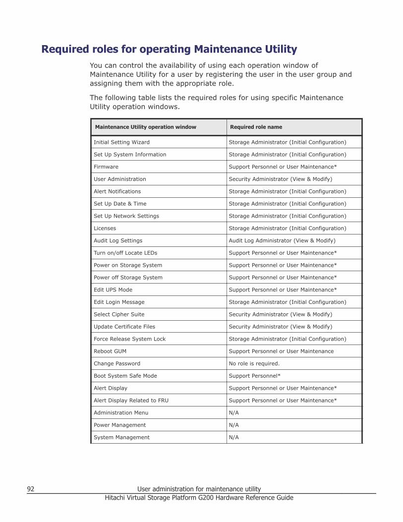
Required roles for operating Maintenance UtilityYou can control the availability of using each operation window ofMaintenance Utility for a user by registering the user in the user group andassigning them with the appropriate role.
The following table lists the required roles for using specific MaintenanceUtility operation windows.
Maintenance Utility operation window Required role name
Initial Setting Wizard Storage Administrator (Initial Configuration)
Set Up System Information Storage Administrator (Initial Configuration)
Firmware Support Personnel or User Maintenance*
User Administration Security Administrator (View & Modify)
Alert Notifications Storage Administrator (Initial Configuration)
Set Up Date & Time Storage Administrator (Initial Configuration)
Set Up Network Settings Storage Administrator (Initial Configuration)
Licenses Storage Administrator (Initial Configuration)
Audit Log Settings Audit Log Administrator (View & Modify)
Turn on/off Locate LEDs Support Personnel or User Maintenance*
Power on Storage System Support Personnel or User Maintenance*
Power off Storage System Support Personnel or User Maintenance*
Edit UPS Mode Support Personnel or User Maintenance*
Edit Login Message Storage Administrator (Initial Configuration)
Select Cipher Suite Security Administrator (View & Modify)
Update Certificate Files Security Administrator (View & Modify)
Force Release System Lock Storage Administrator (Initial Configuration)
Reboot GUM Support Personnel or User Maintenance
Change Password No role is required.
Boot System Safe Mode Support Personnel*
Alert Display Support Personnel or User Maintenance*
Alert Display Related to FRU Support Personnel or User Maintenance*
Administration Menu N/A
Power Management N/A
System Management N/A
92 User administration for maintenance utilityHitachi Virtual Storage Platform G200 Hardware Reference Guide

Maintenance Utility operation window Required role name
Resetting GUM N/A
*• Support Personnel: Operations performed by the service personnel• User Maintenance: Operations performed by the user
Setting up user accountsThis procedure describes how to create a user account and register theaccount to a user group with appropriate roles. You can create up to 20users, including the built-in user.
Procedure
1. In the Maintenance Utility window, click Administration > UserAdministration.
2. In the User Groups tab, click Create User.
3. Create a new user account. Specify the User Name, Account Status,
Authentication and User Group. Click Finish.
User administration for maintenance utility 93Hitachi Virtual Storage Platform G200 Hardware Reference Guide

Item Description
User Name
Account Status The following statuses are available:
Enable = user can use the account.
Disable = user cannot use the account or login to the storage management software.
Authentication The following methods are available:Local = does not use authentication server.Uses a dedicated password for storagemanagement software.
External = uses an authentication server.
4. Confirm the settings, and then click Apply.
94 User administration for maintenance utilityHitachi Virtual Storage Platform G200 Hardware Reference Guide

5. When the completion message appears, click Close.
Disabling user accountsThe following procedure describes how to disable user accounts.
Observe the following guideline:• Log into an account that is different from the user whose account that you
want to disable (you cannot disable the current login user account).• To disable the user account specified by the registered storage system in
the Storage Device List window, click Stop Service for the registeredstorage system. After disabling the user account, click Edit to enable theuser account.
Procedure
1. In the Maintenance Utility window, click Administration > UserAdministration.
2. In the User Groups tab, click the user group to which the user belongs.
User administration for maintenance utility 95Hitachi Virtual Storage Platform G200 Hardware Reference Guide

3. Click the Users tab, and then select the user that you want to disable.
4. Click Edit.5. For Account Status, click Disable, and then click Finish.
96 User administration for maintenance utilityHitachi Virtual Storage Platform G200 Hardware Reference Guide
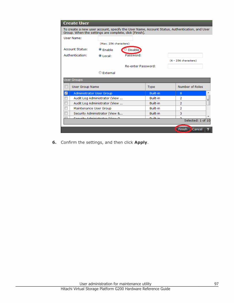
6. Confirm the settings, and then click Apply.
User administration for maintenance utility 97Hitachi Virtual Storage Platform G200 Hardware Reference Guide

7. When a completion message appears, click Close.
98 User administration for maintenance utilityHitachi Virtual Storage Platform G200 Hardware Reference Guide

Removing user accountsSecurity administrators can remove a user account when the account is nolonger in use. Built-in user accounts cannot be deleted. If deleting the currentlogin user account, you can continue the storage management softwareoperation until you log out.
Note: To delete the user account specified by the registered storage systemin the Storage Device List window, click Stop Service of the registeredstorage system. After deletion, click Edit to enable the user account.
Procedure
1. In the Maintenance Utility window, click Administration > UserAdministration.
2. In the User Groups tab, click the user group to which the user belongs.
User administration for maintenance utility 99Hitachi Virtual Storage Platform G200 Hardware Reference Guide
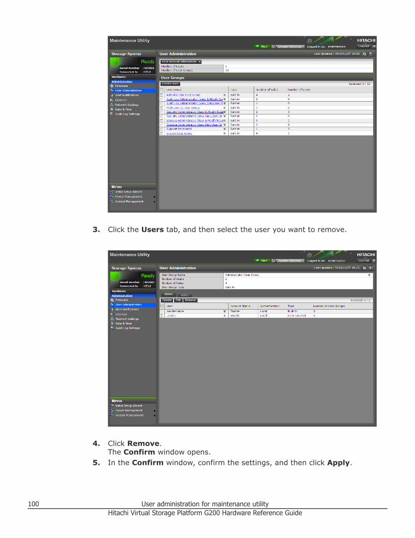
3. Click the Users tab, and then select the user you want to remove.
4. Click Remove.
The Confirm window opens.5. In the Confirm window, confirm the settings, and then click Apply.
100 User administration for maintenance utilityHitachi Virtual Storage Platform G200 Hardware Reference Guide

6. At the completion message, click Close.
User administration for maintenance utility 101Hitachi Virtual Storage Platform G200 Hardware Reference Guide

Backing up user accounts
Procedure
1. Click User Account Information > Backup.2. Specify a storage destination and a file name in the displayed window
and download a file.3. When the following message appears, click Close.
Restoring user account information
Procedure
1. Click User Account Information > Restore
The Restore User Account window opens.2. Specify file names to be restored, and then click Apply.
102 User administration for maintenance utilityHitachi Virtual Storage Platform G200 Hardware Reference Guide
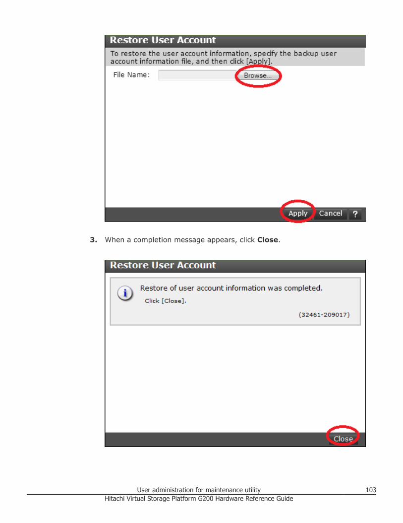
3. When a completion message appears, click Close.
User administration for maintenance utility 103Hitachi Virtual Storage Platform G200 Hardware Reference Guide

104 User administration for maintenance utilityHitachi Virtual Storage Platform G200 Hardware Reference Guide
AStorage system specifications
□ Model lists
□ Replacement parts
□ Hitachi Virtual Storage Platform G200 mechanical specifications (ACpower supply model)
□ Hitachi Virtual Storage Platform G200 mechanical specifications (DCpower supply model)
□ Electrical specifications
□ VSP G200 electrical specifications (DC power supply)
□ Environmental specifications
□ VSP G200 environmental specifications (DC power supply)
□ Battery specifications
□ RAID specifications
□ iSCSI specifications
□ iSCSI standards
□ Regulatory compliance
□ Dense intermix drive tray connection restrictions
□ Physical SVP hardware specifications
Storage system specifications 105Hitachi Virtual Storage Platform G200 Hardware Reference Guide

Model lists
Hitachi Virtual Storage Platform G200 controller model list
CBSS controller components
Part number Part name Quantity
DW800-CBSS 2U chassis 1
AC power supply unit 2
Power cable (0.9 m) 2
Power cable (2.5 m) 2
Backup module (BKM) 2
Front bezel (2U) 1
Binder 1
SAS cable label 2
Controller 2
DW-F800-BM10 Cache flash memory 2
CBSS controller optional components
Part number Part name Quantity
DW-F800-CTLS Controller Board 2
DW-F800-CTLSE Controller Board (Encryption) 2
DW-F800-2HS10S Front end module (10 Gbps SFP- iSCSI)
2-4
DW-F800-2HS10B Front end module (10 Gbpscopper - iSCSI)
2-4
DW-F800-4HF8 Front end module (8 Gbps - FC) 2-4
DW-F800-2HF16 Front end module (16 Gbps 2-port FC)
2-4
DW-F800-4HF32R2 Front end module (32 / 16 Gbps4-port FC)
2-4
DKC-F810I-CM8G Cache memory (8 GB) 4
DKC-F810I-CM16G Cache memory (16 GB) 4
DW-F800-BM10 Cache Flash Memory (CFM) 2
DKC-F810I-200MEM1 200 GB, 2.5-inch, MLC, 12Gbps, flash drive
0-24
106 Storage system specificationsHitachi Virtual Storage Platform G200 Hardware Reference Guide

Part number Part name Quantity
DKC-F810I-300KCM1 300 GB, 2.5-inch, 15k, 6 Gbps,SAS, drive (contains BNST)
0-24
DKC-F810I-300KCMC1 300 GB, 2.5-inch,15k, 6 Gbps,SAS, drive
0-24
DKC-F810I-400MEM 1 400 GB, 2.5-inch, MLC, 12Gbps, SAS, drive
0-24
DKC-F810I-600JCM1 600 GB, 2.5-inch, 10k, 6 Gbps,SAS, drive (contains BNST)
0-24
DKC-F810I-600JCMC1 600 GB, 2.5-inch, 10k, 6 Gbps,SAS, drive
0-24
DKC-F810I-600KGM1 600 GB, 2.5-inch, 15k, 12Gbps, SAS, drive
0-24
DKC-F810I-1R2JCM1 1.2 TB, 2.5-inch, 10k, 6 Gbps,SAS, drive (contains BNST)
0-24
DKC-F810I-1R2JCMC1 1.2 TB, 2.5-inch, 10k, 6 Gbps,SAS, drive
0-24
DKC-F810I-1R8JGM1 1.8 TB, 2.5-inch, 10k, 6 Gbps,SAS, drive
0-24
DKC-F810I-1R9MEM1 1.92 TB, 2.5-inch, MLC, 12Gbps, SAS, drive
0-24
DW-F800-1PS8 SFP for 8 Gbps shortwave 0-16
DW-F800-1PL8 SFP for 8 Gbps longwave 0-16
DW-F800-1PS16 SFP for 16 Gbps shortwave 0-16
DW-F800-1PL16 SFP for 16 Gbps longwave 0-16
DKC-F810I-1PS322 SFP for 32 Gbps shortwave 0-161 The drive capacity values are calculated as 1 G byte =1,000,000,000 bytes. This definition isdifferent from that calculated as 1 k byte =1,024 bytes, which are actually displayed on PCs thatyou are using. The parity group capacity values displayed in the storage management software arecalculated as 1 k byte =1,024 bytes.
2For information about the availability of the 32 Gbps SFPs, contact customer support.
CBSSD controller components
Part number Part name Quantity
DW800-CBSSD 2U chassis 1
DC power supply unit 2
Power cable (1.5 m) 2
Power cable (3 m) 2
Backup module (BKM) 2
Front bezel (2U) 1
Storage system specifications 107Hitachi Virtual Storage Platform G200 Hardware Reference Guide
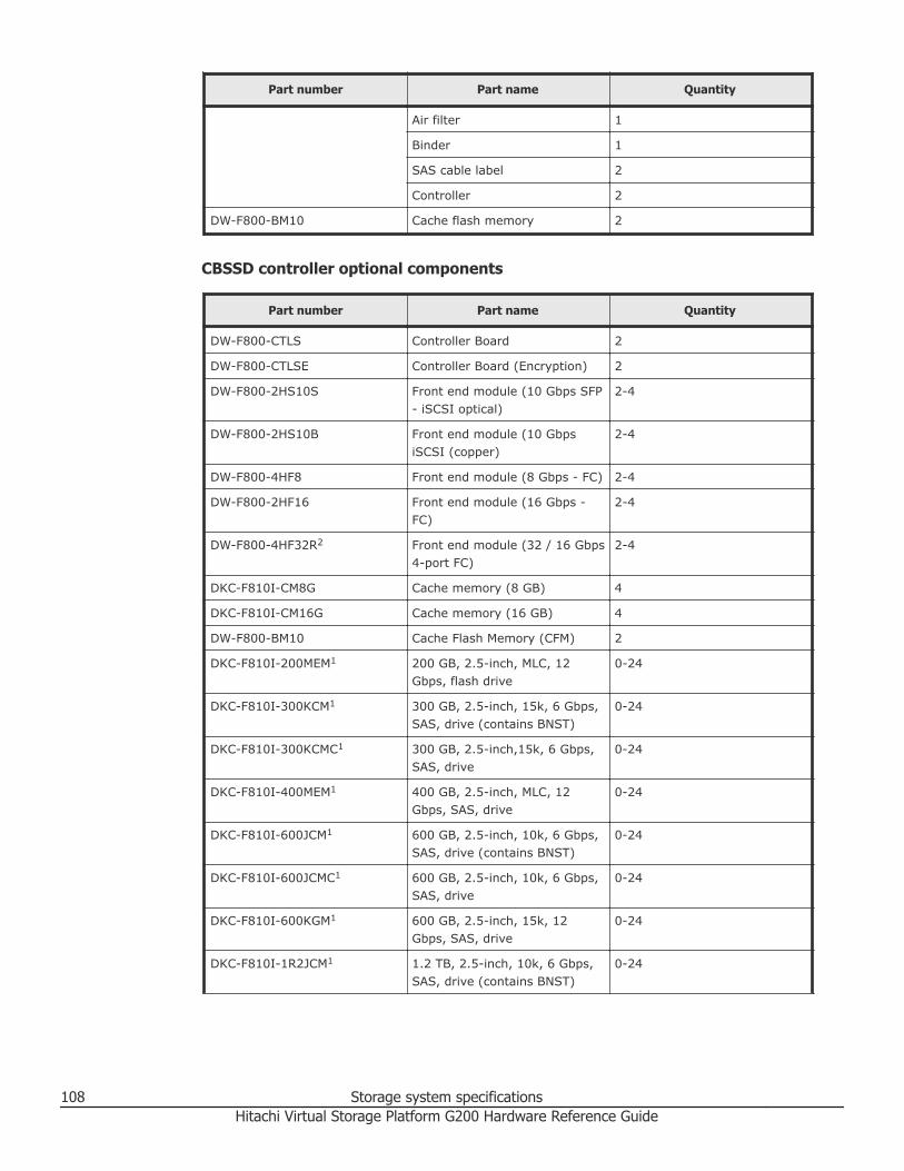
Part number Part name Quantity
Air filter 1
Binder 1
SAS cable label 2
Controller 2
DW-F800-BM10 Cache flash memory 2
CBSSD controller optional components
Part number Part name Quantity
DW-F800-CTLS Controller Board 2
DW-F800-CTLSE Controller Board (Encryption) 2
DW-F800-2HS10S Front end module (10 Gbps SFP- iSCSI optical)
2-4
DW-F800-2HS10B Front end module (10 GbpsiSCSI (copper)
2-4
DW-F800-4HF8 Front end module (8 Gbps - FC) 2-4
DW-F800-2HF16 Front end module (16 Gbps -FC)
2-4
DW-F800-4HF32R2 Front end module (32 / 16 Gbps4-port FC)
2-4
DKC-F810I-CM8G Cache memory (8 GB) 4
DKC-F810I-CM16G Cache memory (16 GB) 4
DW-F800-BM10 Cache Flash Memory (CFM) 2
DKC-F810I-200MEM1 200 GB, 2.5-inch, MLC, 12Gbps, flash drive
0-24
DKC-F810I-300KCM1 300 GB, 2.5-inch, 15k, 6 Gbps,SAS, drive (contains BNST)
0-24
DKC-F810I-300KCMC1 300 GB, 2.5-inch,15k, 6 Gbps,SAS, drive
0-24
DKC-F810I-400MEM1 400 GB, 2.5-inch, MLC, 12Gbps, SAS, drive
0-24
DKC-F810I-600JCM1 600 GB, 2.5-inch, 10k, 6 Gbps,SAS, drive (contains BNST)
0-24
DKC-F810I-600JCMC1 600 GB, 2.5-inch, 10k, 6 Gbps,SAS, drive
0-24
DKC-F810I-600KGM1 600 GB, 2.5-inch, 15k, 12Gbps, SAS, drive
0-24
DKC-F810I-1R2JCM1 1.2 TB, 2.5-inch, 10k, 6 Gbps,SAS, drive (contains BNST)
0-24
108 Storage system specificationsHitachi Virtual Storage Platform G200 Hardware Reference Guide

Part number Part name Quantity
DKC-F810I-1R2JCMC1 1.2 TB, 2.5-inch, 10k, 6 Gbps,SAS, drive
0-24
DKC-F810I-1R8JGM1 1.8 TB, 2.5-inch, 10k, 6 Gbps,SAS, drive
0-24
DKC-F810I-1R6FN1 1.6 TB, 12 Gbps SAS, FlashModule Drive DC2
0-24
DKC-F810I-1R9MEM1 1.92 TB, 2.5-inch, MLC, 12Gbps, SAS, drive
0-24
DKC-F810I-3R2FN1 3.2 TB, 12 Gbps SAS, FlashModule Drive DC2
0-24
DKC-F810I-6R4FN 7 TB (6.4 TiB), 12 Gbps SAS,Flash Module Drive DC2
0-24
DKC-F810I-1PS8 SFP for 8 Gbps shortwave 0-16
DKC-F810I-1PL8 SFP for 8 Gbps longwave 0-16
DKC-F810I-1PS16 SFP for 16 Gbps shortwave 0-16
DKC-F810I-1PL16 SFP for 16 Gbps longwave 0-16
DKC-F810I-1PS322 SFP for 32 Gbps shortwave 0-161 The drive capacity values are calculated as 1 G byte =1,000,000,000 bytes. This definition isdifferent from that calculated as 1 k byte =1,024 bytes, which are actually displayed on PCs thatyou are using. The parity group capacity values displayed in the storage management software arecalculated as 1 k byte =1,024 bytes.
2For information about the availability of the 32 Gbps SFPs, contact customer support.
CBSL controller components
Part number Part name Quantity
DW800-CBSL 2U chassis 1
AC power supply unit 2
Power cable (0.9 m) 2
Power cable (2.5 m) 2
Backup module 2
Front bezel (2U) 1
Binder 1
SAS cable label 2
Controller 2
DW-F800-BM10 Cache flash memory 2
Storage system specifications 109Hitachi Virtual Storage Platform G200 Hardware Reference Guide

CBSL controller optional components
Part number Part name Quantity
DW-F800-CTLS Controller Board 2
DW-F800-CTLSE Controller Board (Encryption) 2
DW-F800-2HS10S Front end module (10 Gbps SFP- iSCSI optical)
2-4
DW-F800-2HS10B Front end module (10 Gbpscopper - iSCSI copper)
2-4
DW-F800-4HF8 Front end module (8 Gbps - FC) 2-4
DW-F800-2HF16 Front end module (16 Gbps -FC)
2-4
DW-F800-4HF32R2 Front end module (32 / 16 Gbps4-port FC)
2-4
DKC-F810I-CM8G Cache memory (8 GB) 4
DKC-F810I-CM16G Cache memory (16 GB) 4
DW-F800-BM10 Cache Flash Memory (CFM) 2
DKC-F810I-400M6M1 400 GB, Flash drive, 3.5-inch 0-12
DKC-F810I-1R2J5M1 1.2 TB, 3.5-inch, 10kmin, 6Gbps SAS drive (contains BNST)
0-12
DKC-F810I-1R2J5MC1 1.2 TB, SAS, 3.5-inch 0-12
DKC-F810I-1R8J6M1 1.8 TB, 3.5-inch, 10kmin, 6Gbps, SAS, drive
0-12
DKC-F810I-4R0H3M1 4 TB, 7.2K 3.5-inch, 6 Gbps,SAS, drive (contains BNST)
0-12
DKC-F810I-4R0H3MC1 4 TB, 7.2K 3.5-inch, 6 Gbps,SAS, drive
0-12
DKC-F810I-6R0H9M1 6 TB, 7.2K 3.5-inch, 12 Gbps,SAS, drive
0-12
DKC-F810I-10RH9M3 10 TB 7.2K, 3.5-inch, 12 Gbps,SAS, drive
0-12
DKC-F810I-1PS8 SFP for 8 Gbps shortwave 0-16
DKC-F810I-1PL8 SFP for 8 Gbps longwave 0-16
DKC-F810I-1PS16 SFP for 16 Gbps shortwave 0-16
DKC-F810I-1PL16 SFP for 16 Gbps longwave 0-16
DKC-F810I-1PS322 SFP for 32 Gbps shortwave 0-161 The drive capacity values are calculated as 1 G byte =1,000,000,000 bytes. This definition isdifferent from that calculated as 1 k byte =1,024 bytes, which are actually displayed on PCs thatyou are using. The parity group capacity values displayed in the storage management software arecalculated as 1 k byte =1,024 bytes.
2For information about the availability of the 32 Gbps SFPs, contact customer support.
110 Storage system specificationsHitachi Virtual Storage Platform G200 Hardware Reference Guide

Part number Part name Quantity3For more information about availability, contact customer support.
CBSLD controller components
Part number Part name Quantity
DW800-CBSLD 2U chassis 1
DC power supply unit 2
Power cable (1.5 m) 2
Power cable (3 m) 2
Backup module 2
Front bezel (2U) 1
Binder 1
Air filter 1
SAS cable label 2
Controller 2
DW-F800-BM10 Cache flash memory 2
CBSLD controller optional components
Part number Part name Quantity
DW-F800-CTLS Controller Board 2
DW-F800-CTLSE Controller Board (Encryption) 2
DW-F800-2HS10S Front end module (10 Gbps SFP- iSCSI optical)
2-4
DW-F800-2HS10B Front end module (10 Gbpscopper - iSCSI copper)
2-4
DW-F800-4HF8 Front end module (8 Gbps - FC) 2-4
DW-F800-2HF16 Front end module (16 Gbps 2-port FC)
2-4
DW-F800-4HF32R2 Front end module (32 / 16 Gbps4-port FC)
2-4
DKC-F810I-CM8G Cache memory (8 GB) 4
DKC-F810I-CM16G Cache memory (16 GB) 4
DW-F800-BM10 Cache Flash Memory (CFM) 2
DKC-F810I-400M6M1 400 GB, 3.5-inch, flash drive 0-12
DKC-F810I-1R2J5M1 1.2 TB, 3.5-inch, 10kmn, 6Gbps, SAS, drive (containsBNST)
0-12
Storage system specifications 111Hitachi Virtual Storage Platform G200 Hardware Reference Guide

Part number Part name Quantity
DKC-F810I-1R8J6M1 1.8 TB, 3.5-inch, 10kmin, 6Gbps, SAS, drive
0-12
DKC-F810I-4R0H3M1 4 TB, 7.2K 3.5-inch, 6 Gbps,SAS, drive (contains BNST)
0-12
DKC-F810I-4R0H3MC 1 4 TB, 7.2K 3.5-inch, 6 Gbps,SAS, drive
0-12
DKC-F810I-6R0H9M1 6 TB, 7.2K 3.5-inch, 12 Gbps,SAS, drive
0-12
DKC-F810I-6R0HLM 6 TB, 7.2K 3.5-inch, 12 Gbps,SAS, drive
0-12
DKC-F810I-10RH9M3 10 TB 7.2K, 3.5-inch, 12 Gbps,SAS, drive
0-12
DKC-F810I-1R6FN1 1.75 TB, 12 Gbps SAS, FlashModule Drive DC2
0-12
DKC-F810I-3R2FN1 3.5 TB, 12 Gbps SAS, FlashModule Drive DC2
0-12
DKC-F810I-6R4FN 7 TB (6.4 TiB), 12 Gbps SAS,Flash Module Drive DC2
0-12
DKC-F810I-1PS8 SFP for 8 Gbps shortwave 0-16
DKC-F810I-1PL8 SFP for 8 Gbps longwave 0-16
DKC-F810I-1PS16 SFP for 16 Gbps shortwave 0-16
DKC-F810I-1PL16 SFP for 16 Gbps longwave 0-16
DKC-F810I-1PS32 2 SFP for 32 Gbps shortwave 0-161 The drive capacity values are calculated as 1 G byte =1,000,000,000 bytes. This definition isdifferent from that calculated as 1 k byte =1,024 bytes, which are actually displayed on PCs thatyou are using. The parity group capacity values displayed in the storage management software arecalculated as 1 k byte =1,024 bytes.
2For information about the availability of the 32 Gbps SFPs, contact customer support.
3For more information about availability, contact customer support.
Drive tray model lists
SFF drive tray components (AC power)
Model number Part name Quantity
DW-F800-DBS and DW-F800-DBSC
2U chassis 1
ENC 2
AC power supply unit 2
Power cable (0.9 m) 2
Power cable (2.5 m) 2
112 Storage system specificationsHitachi Virtual Storage Platform G200 Hardware Reference Guide

Model number Part name Quantity
Front bezel (2U) 1
SFF drive tray components (DC power)
Model number Part name Quantity
DW-F800-DBSD 2U chassis 1
ENC 2
DC power supply unit 2
Power cable (1.5 m) 2
Power cable (3 m) 2
Front bezel (2U) 1
Air filter 1
SFF drive tray optional components
Model number Part name Quantity
DKC-F810I-200MEM1 200 GB, MLC, 12 Gbps, SFF,flash drive
0-24
DKC-F810I-300KCM1 300GB, 15kmin, 6 Gbps, SAS,SFF, drive (contains BNST)
0-24
DKC-F810I-400MEM1 400GB, MLC, 12 Gbps, SFF,flash drive
0-24
DKC-F810I-600JCM1 600 GB, 10kmin, 6 Gbps, SAS,SFF, drive (contains BNST)
0-24
DKC-F810I-600KGM1 600 GB, 15kmin, 6 Gbps, SAS,SFF, drive
0-24
DKC-F810I-1R2JCM1 1.2 TB, 10kmin, 6 Gbps, SAS,SFF, drive (contains BNST)
0-24
DKC-F810I-1R9MEM1 1.92 TB, 2.5-inch, MLC, 12Gbps, SAS, drive
0-24
11 The drive capacity values are calculated as 1 G byte =1,000,000,000 bytes. This definition isdifferent from that calculated as 1 k byte =1,024 bytes, which are actually displayed on PCs thatyou are using. The parity group capacity values displayed in the storage management software arecalculated as 1 k byte =1,024 bytes.
LFF drive tray components (AC power)
Model number Part name Quantity
DW-F800-DBL and DW-F800-DBLC
2U chassis 1
Storage system specifications 113Hitachi Virtual Storage Platform G200 Hardware Reference Guide

Model number Part name Quantity
ENC 2
AC power supply unit 2
Power cable (0.9 m) 2
Power cable (2.5 m) 2
Front bezel (2U) 1
LFF drive tray components (DC power)
Model number Part name Quantity
DW-F800-DBLD 2U chassis 1
ENC 2
DC power supply unit 2
Power cable (1.5 m) 2
Power cable (3 m) 2
Front bezel (2U) 1
Air filter 1
Optional LFF drive tray components
Model number Part name Quantity
DKC-F810I-400M6M1 400 GB, LFF, Flash drive 0-12
DKC-F810I-1R2J5MC1 1.2 TB, SAS, LFF, drive 0-12
DKC-F810I-1R8J6M1 1.8 TB, 10k, 6 Gbps, SAS, LFF,drive
0-12
DKC-F810I-4R0H3M1 4 TB, 7.2K, 6 Gbps, SAS, LFF,drive (contains BNST)
0-12
DKC-F810I-6R0H9M1 6 TB, 7.2K, 12 Gbps, SAS, LFF,drive
0-12
DKC-F810I-10RH9M2 10 TB, 7.2K, 12 Gbps, SAS, LFF,drive
0-12
1 The drive capacity values are calculated as 1 G byte =1,000,000,000 bytes. This definition isdifferent from that calculated as 1 k byte =1,024 bytes, which are actually displayed on PCs thatyou are using. The parity group capacity values displayed in the storage management software arecalculated as 1 k byte =1,024 bytes.
2For more information about availability, contact customer support.
114 Storage system specificationsHitachi Virtual Storage Platform G200 Hardware Reference Guide
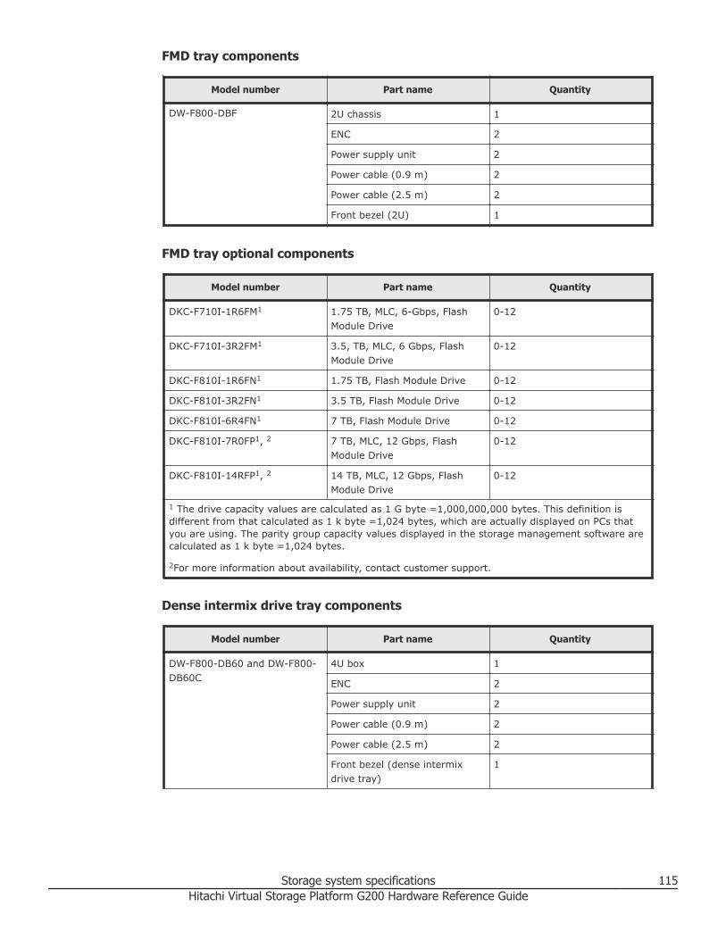
FMD tray components
Model number Part name Quantity
DW-F800-DBF 2U chassis 1
ENC 2
Power supply unit 2
Power cable (0.9 m) 2
Power cable (2.5 m) 2
Front bezel (2U) 1
FMD tray optional components
Model number Part name Quantity
DKC-F710I-1R6FM1 1.75 TB, MLC, 6-Gbps, FlashModule Drive
0-12
DKC-F710I-3R2FM1 3.5, TB, MLC, 6 Gbps, FlashModule Drive
0-12
DKC-F810I-1R6FN1 1.75 TB, Flash Module Drive 0-12
DKC-F810I-3R2FN1 3.5 TB, Flash Module Drive 0-12
DKC-F810I-6R4FN1 7 TB, Flash Module Drive 0-12
DKC-F810I-7R0FP1, 2 7 TB, MLC, 12 Gbps, FlashModule Drive
0-12
DKC-F810I-14RFP1, 2 14 TB, MLC, 12 Gbps, FlashModule Drive
0-12
1 The drive capacity values are calculated as 1 G byte =1,000,000,000 bytes. This definition isdifferent from that calculated as 1 k byte =1,024 bytes, which are actually displayed on PCs thatyou are using. The parity group capacity values displayed in the storage management software arecalculated as 1 k byte =1,024 bytes.
2For more information about availability, contact customer support.
Dense intermix drive tray components
Model number Part name Quantity
DW-F800-DB60 and DW-F800-DB60C
4U box 1
ENC 2
Power supply unit 2
Power cable (0.9 m) 2
Power cable (2.5 m) 2
Front bezel (dense intermixdrive tray)
1
Storage system specifications 115Hitachi Virtual Storage Platform G200 Hardware Reference Guide

Model number Part name Quantity
DW-F800-SCQ3 SAS cable (3 m), including 2omega clips(DW-F800-SCQ3)
2
Dense intermix drive tray optional components (VSP Gx00 models only)
Model number Part name Quantity
DKC-F810I-400M8M1 400 GB, MLC, 12 Gbps, flashdrive
0-60
DKC-F810I-1R2J7M1 1.2 TB, 10k, 6 Gbps, SAS, SFF,drive (contains BNST)
0-60
DKC-F810I-1R2J7MC1 1.2 TB, 10k, 6 Gbps, SAS, SFF,drive
0-60
DKC-F810I-1R8J8M1 1.8 TB, 10k, 6 Gbps, SAS, LFFdrive
0-60
DKC-F810I-4R0H4M1 4 TB, 7.2K, 6 Gbps, SAS, LFF,drive (contains BNST)
0-60
DKC-F810I-4R0H4MC1 4 TB, 7.2K, 6 Gbps, SAS, LFF,drive
0-60
DKC-F810I-6R0HLM1 6 TB, 7.2K, 12 Gbps, SAS, LFF,drive
0-60
DKC-F810I-10RHLM1, 2 10 TB, 7.2K, 12 Gbps, SAS, LFF,drive
0-60
1 The drive capacity values are calculated as 1 G byte =1,000,000,000 bytes. This definition isdifferent from that calculated as 1 k byte =1,024 bytes, which are actually displayed on PCs thatyou are using. The parity group capacity values displayed in the storage management software arecalculated as 1 k byte =1,024 bytes.
2For more information about availability, contact customer support.
Other model listNumbers in parentheses show the quantities of the components.
Power cables
Model number Specification
DW-F800-J1K 2.5 m, 2-pole power cable with groundingterminal (AC 125 V, 13 A or 15 A)
DW-F800-J2H 2.5 m, 2-pole power cable with groundingterminal (AC 250 V, 13 A or 15 A)
DW-F800-J2H5 5.0 m, 2-pole power cable with groundingterminal (AC 250 V, 13 A or 15 A)
116 Storage system specificationsHitachi Virtual Storage Platform G200 Hardware Reference Guide

Model number Specification
DW-F800-J2H10 10.0 m, 2-pole power cable with groundingterminal (AC 250 V, 13 A or 15 A)
A-F6516-P620 Power cable for PDU (1)
A-F6516-P630 Power cable for PDU (1)
SAS cables
Model number Specification
DW-F800-SCQ1 1 m SAS cable, including omega clips (2)
DW-F800-SCQ1F 1.5 m SAS cable, including omega clips (2)
DW-F800-SCQ3 3 m SAS cable, including omega clips (2)
DW-F800-SCQ5 5 m SAS cable, including omega clips (2)
DW-F800-SCQ10A 10 m SAS optical cable
DW-F800-SCQ30A 30 m SAS optical cable
DW-F800-SCQ1HA 100 m SAS optical cable
Optical cables
Model number Specification
A-6515-GM5L 5 m LC-LC optical cable for optical
A-6515-GM10L 10 m LC-LC optical cable for optical
A-6515-GM20L 20 m LC-LC optical cable for optical
A-6515-GM30L 30 m LC-LC optical cable for optical
A-6515-GM40L 40 m LC-LC optical cable for optical
A-6515-GM50L 50 m LC-LC optical cable for optical
A-6515-GM1JL 100 m LC-LC optical cable for optical
A-6515-GS10L 10 m LC-LC optical cable for optical
A-6515-GS20L 20 m LC-LC optical cable for optical
A-6515-GS30L 30 m LC-LC optical cable for optical
A-6515-GS50L 50 m LC-LC optical cable for optical
A-6515-GS1JL 100 m LC-LC optical cable for optical
A-6515-HM5L 5 m LC-LC optical cable for optical
A-6515-HM10L 10 m LC-LC optical cable for optical
A-6515-HM20L 20 m LC-LC optical cable for optical
A-6515-HM30L 30 m LC-LC optical cable for optical
A-6515-HM50L 50 m LC-LC optical cable for optical
Storage system specifications 117Hitachi Virtual Storage Platform G200 Hardware Reference Guide

Model number Specification
A-6515-HM100L 100 m LC-LC optical cable for optical
A-6515-HM200L 200 m LC-LC optical cable for optical
A-6515-HM300L 300 m LC-LC optical cable for optical
A-6515-JM5L 5 m LC-LC optical cable for optical
A-6515-JM10L 10 m LC-LC optical cable for optical
A-6515-JM20L 20 m LC-LC optical cable for optical
A-6515-JM30L 30 m LC-LC optical cable for optical
A-6515-JM50L 50 m LC-LC optical cable for optical
A-6515-JM100L 100 m LC-LC optical cable for optical
A-6515-JM200L 200 m LC-LC optical cable for optical
A-6515-JM300L 300 m LC-LC optical cable for optical
Replacement partsPart replacement is required to maintain high performance. Replacement ofparts is covered by the maintenance service contract.
Battery unit
Replacement period
Three years.
Treatment
Use the storage system in a place where the ambient temperature is 86°F(30°C) or less on average.
Periodic parts replacement is required. For customers with maintenanceservice contracts, parts are replaced periodically in keeping with the terms ofthe contract.
Note: The battery is designed to protect the data in the cache memory in anemergency, such as a sudden power failure. In these situations, follow thenormal power down procedure. If not, the battery might reach its lifespanearlier than expected and become unusable within three years. Whenreplacing the battery, follow the given procedure for disposing a used battery.
118 Storage system specificationsHitachi Virtual Storage Platform G200 Hardware Reference Guide
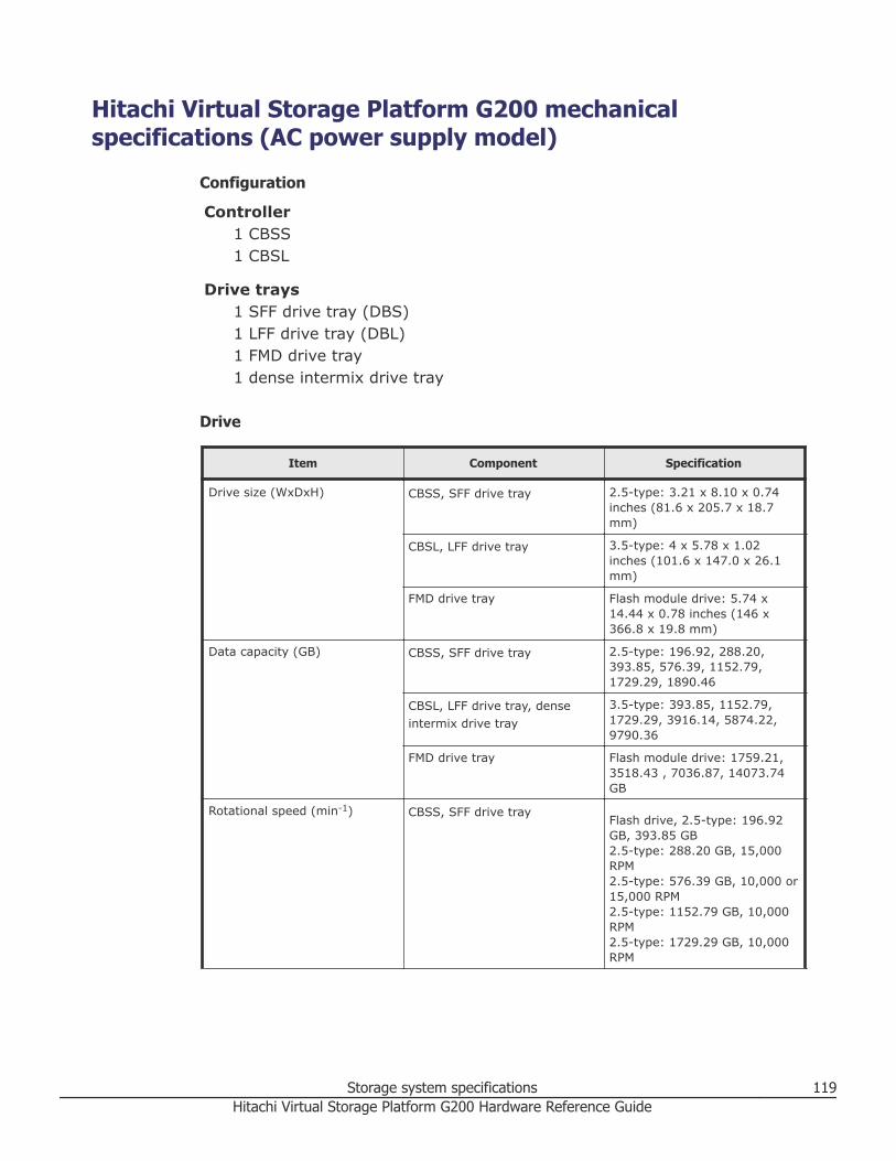
Hitachi Virtual Storage Platform G200 mechanicalspecifications (AC power supply model)
Configuration
Controller1 CBSS1 CBSL
Drive trays1 SFF drive tray (DBS)1 LFF drive tray (DBL)1 FMD drive tray1 dense intermix drive tray
Drive
Item Component Specification
Drive size (WxDxH) CBSS, SFF drive tray 2.5-type: 3.21 x 8.10 x 0.74inches (81.6 x 205.7 x 18.7mm)
CBSL, LFF drive tray 3.5-type: 4 x 5.78 x 1.02inches (101.6 x 147.0 x 26.1mm)
FMD drive tray Flash module drive: 5.74 x14.44 x 0.78 inches (146 x366.8 x 19.8 mm)
Data capacity (GB) CBSS, SFF drive tray 2.5-type: 196.92, 288.20,393.85, 576.39, 1152.79,1729.29, 1890.46
CBSL, LFF drive tray, denseintermix drive tray
3.5-type: 393.85, 1152.79,1729.29, 3916.14, 5874.22,9790.36
FMD drive tray Flash module drive: 1759.21,3518.43 , 7036.87, 14073.74GB
Rotational speed (min-1) CBSS, SFF drive trayFlash drive, 2.5-type: 196.92GB, 393.85 GB2.5-type: 288.20 GB, 15,000RPM2.5-type: 576.39 GB, 10,000 or15,000 RPM2.5-type: 1152.79 GB, 10,000RPM2.5-type: 1729.29 GB, 10,000RPM
Storage system specifications 119Hitachi Virtual Storage Platform G200 Hardware Reference Guide
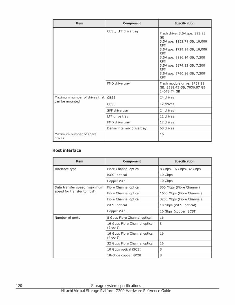
Item Component Specification
CBSL, LFF drive trayFlash drive, 3.5-type: 393.85GB3.5-type: 1152.79 GB, 10,000RPM3.5-type: 1729.29 GB, 10,000RPM3.5-type: 3916.14 GB, 7,200RPM3.5-type: 5874.22 GB, 7,200RPM3.5-type: 9790.36 GB, 7,200RPM
FMD drive tray Flash module drive: 1759.21GB, 3518.43 GB, 7036.87 GB,14073.74 GB
Maximum number of drives thatcan be mounted
CBSS 24 drives
CBSL 12 drives
SFF drive tray 24 drives
LFF drive tray 12 drives
FMD drive tray 12 drives
Dense intermix drive tray 60 drives
Maximum number of sparedrives
16
Host interface
Item Component Specification
Interface type Fibre Channel optical 8 Gbps, 16 Gbps, 32 Gbps
iSCSI optical 10 Gbps
Copper iSCSI 10 Gbps
Data transfer speed (maximumspeed for transfer to host)
Fibre Channel optical 800 Mbps (Fibre Channel)
Fibre Channel optical 1600 Mbps (Fibre Channel)
Fibre Channel optical 3200 Mbps (Fibre Channel)
iSCSI optical 10 Gbps (iSCSI optical)
Copper iSCSI 10 Gbps (copper iSCSI)
Number of ports 8 Gbps Fibre Channel optical 16
16 Gbps Fibre Channel optical(2-port)
8
16 Gbps Fibre Channel optical(4-port)
16
32 Gbps Fibre Channel optical 16
10 Gbps optical iSCSI 8
10-Gbps copper iSCSI 8
120 Storage system specificationsHitachi Virtual Storage Platform G200 Hardware Reference Guide

Item Component Specification
Transferred block size 512 bytes
Maximum number of hostsusing a Fibre Channel switch
255
Maximum number of hostsusing a network switch
255
RAID specifications
D: Data drive, P: Parity drive.
Although the storage system with a configuration of RAID 1, RAID 5, or RAID6 provides data reliability enhanced by redundancy, there is a chance thatuser data could be lost due to an unexpected host, storage system hardware,or software failure. Therefore, users are requested to back up all data.
Item Drive tray
RAID Level SAS, SAS 7.2k, flash drives mounted
RAID 1 2D+2D, 4D+4D
RAID 5 3D+1P, 4D+1P, 6D+1P, 7D+1P
RAID 6 6D+2P, 12D+2P, 14D+2P
Item Specification
Maximum number of parity groups 88
Maximum volume size 3 TB (or 4 TB when using the LDEVs of otherstorage systems)
Maximum volumes/host groups and iSCSItargets
2,048
Maximum volumes/parity groups 2,048
Internal logic specifications
Item Component Specifications
Shared memory Flash memory 32 MB
L3 cache memory 4 MB
SDRAM 1 GB
Data assurance method Data bus Parity
Cache memory ECC (1 bit for correction, 2 bitsfor detection)
Drive Data assurance code
Storage system specifications 121Hitachi Virtual Storage Platform G200 Hardware Reference Guide

Physical specifications
Item Component Specifications
Start-up time (min)1 Controller Standard: 5 to 8
Drive trays Standard: 5 to 8
Chassis size ControllerWxDxH: 19 x 32 x 3.5 inches(483 x 813 x 88 mm)
SFF drive trayWxDxH: 19 x 22.2 x 3.5 inches(483 x 565 x 88.2 mm)
LFF drive trayWxDxH: 19 x 22.2 x 3.5 inches(483 x 565 x 88.2 mm)
FMD drive trayWxDxH: 19 x 30 x 3.4 inches(483 x 762 x 87 mm)
Dense intermix drive trayWxDxH: 19 x 40.5 x 7 inches(482 x 1029 x 176 mm)
Mass (approximate)2 CBSS97 lbs (44 kg)
CBSL101.4 lbs (46 kg)
SFF drive tray51 lbs (23 kg)
LFF drive tray59.5 lbs (27 kg)
FMD drive tray84 lbs (38 kg)
Dense intermix drive tray198 lbs (90 kg)
Required height CBSS, CBSL 2
SFF drive tray 2
LFF drive tray 2
FMD drive tray 2
Dense intermix drive tray 4
Notes1. The startup time might be longer in proportion to the number of drive trays connected. With a
maximum configuration of 1 controller and 19 drive trays, startup time is approximately 8minutes.
2. Value of maximum configuration when all controllers and drives are mounted.3. Mixing SFF, LFF, FMD, and dense intermix drive trays might affect the maximum number of
drives that can be mounted.
Cache specifications
Item Specifications
Capacity (GB) 64 GB
Control method Read LRU, Write after
122 Storage system specificationsHitachi Virtual Storage Platform G200 Hardware Reference Guide

Item Specifications
Battery backup Provided
Backup duration Unrestricted (saving to a nonvolatile memory)
Data in the cache memory is preserved against power failures. If a poweroutage occurs, data in cache memory is written to drives.
When the storage system enters Cache Backup mode, the amber WARNINGLED goes on to when the system starts. This warning indicates that thebattery charge has dropped significantly and the remaining battery capacityis not sufficient; the storage system will continue operating with the WriteCache function disabled.
When the battery is charged, the warning indication disappears, and thestorage system continues the operation in the Write Cache function.
The warning indication disappears within six hours. Even when the warning isshown, normal operation is assured in Write-Through. Read and writeperformance is lowered because the Write Cache function is disabled.
If the storage system is not charged for more than six months, the batterycan become overcharged and sustain unrecoverable damage. To avoid thissituation, charge the battery more than 3 hours every six months.
Insulation performance
Item Specifications
Insulation withstand voltage AC 1,500 V (100 mA, 1 min)
Insulation resistance DC 500 V, 10 M Ω or more
Hitachi Virtual Storage Platform G200 mechanicalspecifications (DC power supply model)
Configuration
Controller1 CBSSD1 CBSLD
Drive trays1 SFF drive tray (DBSD)1 LFF drive tray (DBLD)
Storage system specifications 123Hitachi Virtual Storage Platform G200 Hardware Reference Guide

Item Component Specification
Drive size (WxDxH) CBSSD, SFF drive tray 2.5-type: 3.21 x 8.10 x 0.74inches (81.6 x 205.7 x 18.7mm)
CBSLD, LFF drive tray 3.5-type: 4 x 5.78 x 1.02inches (101.6 x 147.0 x 26.1mm)
Data capacity (GB) CBSSD, SFF drive tray 2.5-type: 196.92, 288.20,393.85, 576.39, 1152.79,1729.29, 1890.46
CBSLD, LFF drive tray 3.5-type: 393.85, 1152.79,1729.29, 3916.14, 5874.22,9790.36
Rotational speed (min-1) CBSSD, SFF drive trayFlash drive, 2.5-type: 196.92GB, 393.85 GB2.5-type: 288.20 GB, 15,000RPM2.5-type: 576.39 GB, 10,000 or15,000 RPM2.5-type: 1152.79 GB, 10,000RPM2.5-type: 1729.29 GB, 10,000RPM
CBSLD, LFF drive trayFlash drive, 3.5-type: 393.85GB3.5-type: 1152.79 GB, 10,000RPM3.5-type: 1729.29 GB, 10,000RPM3.5-type: 3916.14 GB, 7,200RPM3.5-type: 5874.22 GB, 7,200RPM3.5-type: 9790.36 GB, 7,200RPM
Maximum number of drives thatcan be mounted
CBSSD, SFF drive tray 24 drives
CBSLD, LFF drive tray 12 drives
Maximum number of sparedrives
16
Host interface
Item Component Specification
Interface type Fibre Channel optical 8 Gbps, 16 Gbps, 32 Gbps
iSCSI optical 10 Gbps
Copper iSCSI 10 Gbps
Data transfer speed (maximumspeed for transfer to host)
Fibre Channel optical 800 Mbps (Fibre Channel)
Fibre Channel optical 1600 Mbps (Fibre Channel)
124 Storage system specificationsHitachi Virtual Storage Platform G200 Hardware Reference Guide

Item Component Specification
Fibre Channel optical 3200 Mbps (Fibre Channel)
iSCSI optical 10 Gbps (iSCSI optical)
Copper iSCSI 10 Gbps (copper iSCSI)
Number of ports 8 Gbps Fibre Channel optical 16
16 Gbps Fibre Channel optical(2-port)
8
16 Gbps Fibre Channel optical(4-port)
16
32 Gbps Fibre Channel optical 16
10 Gbps optical iSCSI 8
10 Gbps copper iSCSI 8
Transferred block size 512 bytes
Maximum number of hostsusing a Fibre Channel switch
255
Maximum number of hostsusing a network switch
255
RAID specifications
D: Data drive, P: Parity drive.
Although the storage system with a configuration of RAID 1, RAID 5, or RAID6 provides data reliability enhanced by redundancy, there is a chance thatuser data could be lost due to an unexpected host, storage system hardware,or software failure. Therefore, users are requested to back up all data.
Item Drive tray
RAID Level SAS, SAS 7.2k, flash drives mounted
RAID 1 2D+2D, 4D+4D
RAID 5 3D+1P, 4D+1P, 6D+1P, 7D+1P
RAID 6 6D+2P, 12D+2P, 14D+2P
Item Specification
Maximum number of parity groups 88
Maximum volume size 3 TB (or 4 TB when using the LDEVs of otherstorage systems)
Maximum volumes/host groups and iSCSItargets
2,048
Maximum volumes/parity groups 2,048
Storage system specifications 125Hitachi Virtual Storage Platform G200 Hardware Reference Guide
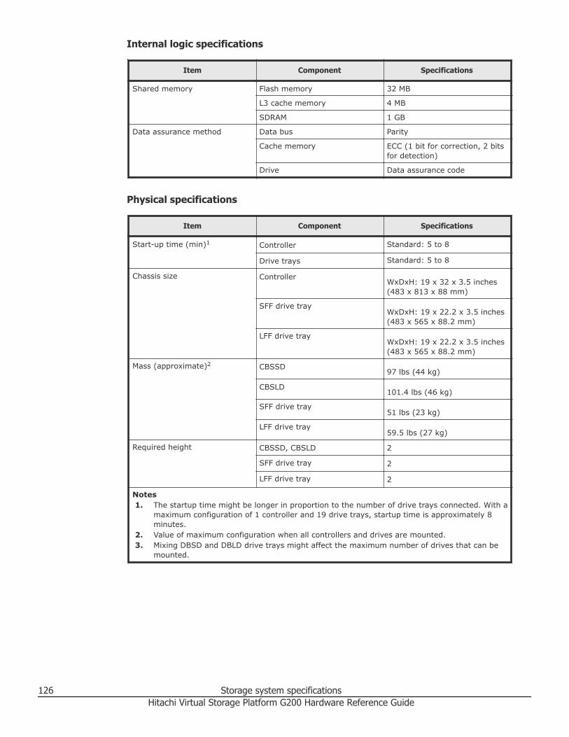
Internal logic specifications
Item Component Specifications
Shared memory Flash memory 32 MB
L3 cache memory 4 MB
SDRAM 1 GB
Data assurance method Data bus Parity
Cache memory ECC (1 bit for correction, 2 bitsfor detection)
Drive Data assurance code
Physical specifications
Item Component Specifications
Start-up time (min)1 Controller Standard: 5 to 8
Drive trays Standard: 5 to 8
Chassis size ControllerWxDxH: 19 x 32 x 3.5 inches(483 x 813 x 88 mm)
SFF drive trayWxDxH: 19 x 22.2 x 3.5 inches(483 x 565 x 88.2 mm)
LFF drive trayWxDxH: 19 x 22.2 x 3.5 inches(483 x 565 x 88.2 mm)
Mass (approximate)2 CBSSD97 lbs (44 kg)
CBSLD101.4 lbs (46 kg)
SFF drive tray51 lbs (23 kg)
LFF drive tray59.5 lbs (27 kg)
Required height CBSSD, CBSLD 2
SFF drive tray 2
LFF drive tray 2
Notes1. The startup time might be longer in proportion to the number of drive trays connected. With a
maximum configuration of 1 controller and 19 drive trays, startup time is approximately 8minutes.
2. Value of maximum configuration when all controllers and drives are mounted.3. Mixing DBSD and DBLD drive trays might affect the maximum number of drives that can be
mounted.
126 Storage system specificationsHitachi Virtual Storage Platform G200 Hardware Reference Guide
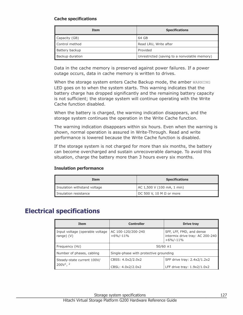
Cache specifications
Item Specifications
Capacity (GB) 64 GB
Control method Read LRU, Write after
Battery backup Provided
Backup duration Unrestricted (saving to a nonvolatile memory)
Data in the cache memory is preserved against power failures. If a poweroutage occurs, data in cache memory is written to drives.
When the storage system enters Cache Backup mode, the amber WARNINGLED goes on to when the system starts. This warning indicates that thebattery charge has dropped significantly and the remaining battery capacityis not sufficient; the storage system will continue operating with the WriteCache function disabled.
When the battery is charged, the warning indication disappears, and thestorage system continues the operation in the Write Cache function.
The warning indication disappears within six hours. Even when the warning isshown, normal operation is assured in Write-Through. Read and writeperformance is lowered because the Write Cache function is disabled.
If the storage system is not charged for more than six months, the batterycan become overcharged and sustain unrecoverable damage. To avoid thissituation, charge the battery more than 3 hours every six months.
Insulation performance
Item Specifications
Insulation withstand voltage AC 1,500 V (100 mA, 1 min)
Insulation resistance DC 500 V, 10 M Ω or more
Electrical specificationsItem Controller Drive tray
Input voltage (operable voltagerange) (V)
AC 100-120/200-240+6%/-11%
SFF, LFF, FMD, and denseintermix drive tray: AC 200-240+6%/-11%
Frequency (Hz) 50/60 ±1
Number of phases, cabling Single-phase with protective grounding
Steady-state current 100V/200V1, 2
CBSS: 4.0x2/2.0x2
CBSL: 4.0x2/2.0x2
SFF drive tray: 2.4x2/1.2x2
LFF drive tray: 1.9x2/1.0x2
Storage system specifications 127Hitachi Virtual Storage Platform G200 Hardware Reference Guide

Item Controller Drive tray
FMD drive tray: 2.6x2/1.3x2
Dense intermix drive tray: -/3.0x2
Current rating of breaker/fuse(A)
16.0 (each electrical)
Heat value (normal) (kJ/h) CBSS: 1800 or less
CBSL 1550 or less
SFF drive tray: 1120 or less
LFF drive tray: 940 or less
FMD drive tray: 1300/1520 orless
Dense intermix drive tray: 3460or less
Steady-state power (VA/W)3 CBSS: 800/760 or less
CBSL: 800/760 or less
SFF drive tray: 480/460 or less
LFF drive tray: 380/350 or less
FMD drive tray: 520/490 or less
Dense intermix drive tray:1200/1160 or less
Power consumption (VA/W) CBSS: 520/500 or less
CBSL: 450/430 or less
SFF drive tray: 320/310 or less
LFF drive tray: 280/260 or less
FMD drive tray: 440/420 or less
Dense intermix drive tray:1000/960 or less
Notes:1. The power current of Nx2 described in this table is required for a single power unit.2. If one power unit fails, another power unit requires electric current for the two power units.
Therefore, plan the power supply facility so that the current-carrying capacity for one powerunit can provide the total capacity for two power units.
3. This table shows the power requirement (100 V or 200 V) for the maximum configuration .The actual required power might exceed the value shown in the table when the tolerance isincluded.
VSP G200 electrical specifications (DC power supply)
Input power specifications
Item CBSSD CBSLD DBSD DBLD
Rated inputvoltage (v)
DC -60 to -48
Input voltagefluctuation (v)
DC -72 to -40
128 Storage system specificationsHitachi Virtual Storage Platform G200 Hardware Reference Guide

Item CBSSD CBSLD DBSD DBLD
Input voltageinstantfluctuation (v)
DC -75 to -36
Inrush current(v)
35 (Ta = 25°C, in the range of rated input voltage, except when voltagefluctuates)
Input shape Connection by connector. Connect the terminal by the dedicated cable withterminal. Connector: Positronic Industries Inc., PCS Series
Heat value(kJ/h)
1800 1550 1120 940
Steady-statepower (W)
760 760 460 350
Powerconsumption(W)
500 430 310 260
Input current(A)
15.9 15.9 9.6 7.3
UPS No connection
Remote adapter No connection
Environmental specificationsTemperature
Caution: The following VSP Gx00/Fx00 storage system components are notsupported in high-temperature environments. Do not operate the followingcomponents at temperatures of 40°C or higher:• DB60 dense drive tray• HDS provided service processor (SVP) server• First-generation FMDs (non-DC2 FMDs)
State Controller SFF, LFF drivetrays Dense intermix drive tray
Operating 50°F to 104°F(10°C to 40°C)
50°F to 104°F(10°C to 40°C)
50°F to 95°F (10°C to 35°C)
Non-operating 14°F to 122°F(-10°C to 50°C)
14°F to 122°F(-10°C to 50°C)
14°F to 122°F (-10°C to 50°C)
Transport, storage -22°F to 140°F(-30°C to 60°C)
-22°F to 140°F(-30°C to 60°C)
-22°F to 140°F (-30°C to 60°C)
Storage system specifications 129Hitachi Virtual Storage Platform G200 Hardware Reference Guide

State Controller SFF, LFF drivetrays Dense intermix drive tray
Temperaturechange rate(°C/h)
10 or less
State Controller FMD drive trays
Operating 50°F to 104°F(10°C to 40°C)
DKC-F710I-1R6FM or DKC-F710I-3R2FM drive is installed:50°F to 95°F (10°C to 35°C)
Operating 50°F to 104°F(10°C to 40°C)
DKC-F810I-1R6FN/3R2FN/6R4FN/7R0FP/14RFP drive isinstalled: 50°F to 104°F (10°C to 40°C)
Non-operating 14°F to 122°F(-10°C to 50°C)
14°F to 95°F (-10°C to 35°C)
Transport, storage -22°F to 140°F(-30°C to 60°C)
-22°F to 122°F (-30°C to 50°C)
Temperaturechange rate(°C/h)
10 or less
Humidity
State Percentage
Operating 8 to 80
Non-operating 8 to 90
Transport, storage (%) 5 to 95
Maximum wet bulb temperature (°C) 29 (non-condensing)
Vibration
State m/s2
Operating 2.5 or lessWithin 5 seconds (resonance point: 10 Hz orless)
Non-operating 5.0 or less at 5 Hz to 300 Hz (no damage toproduct)9.8 (1.0 G)
Within 5 seconds (resonance point: 10 Hz orless)
Transport (packed) 5.0 or less
130 Storage system specificationsHitachi Virtual Storage Platform G200 Hardware Reference Guide
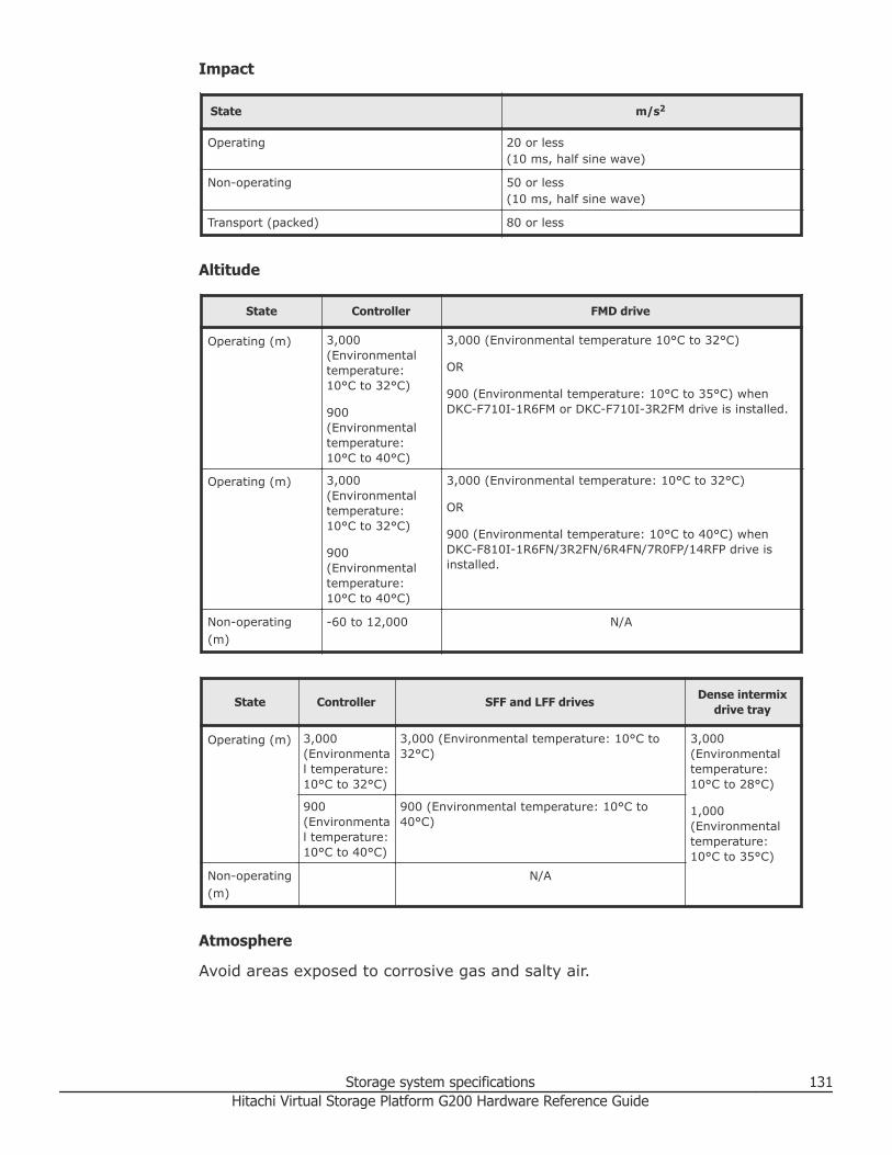
Impact
State m/s2
Operating 20 or less(10 ms, half sine wave)
Non-operating 50 or less(10 ms, half sine wave)
Transport (packed) 80 or less
Altitude
State Controller FMD drive
Operating (m) 3,000(Environmentaltemperature:10°C to 32°C)
900(Environmentaltemperature:10°C to 40°C)
3,000 (Environmental temperature 10°C to 32°C)
OR
900 (Environmental temperature: 10°C to 35°C) whenDKC-F710I-1R6FM or DKC-F710I-3R2FM drive is installed.
Operating (m) 3,000(Environmentaltemperature:10°C to 32°C)
900(Environmentaltemperature:10°C to 40°C)
3,000 (Environmental temperature: 10°C to 32°C)
OR
900 (Environmental temperature: 10°C to 40°C) whenDKC-F810I-1R6FN/3R2FN/6R4FN/7R0FP/14RFP drive isinstalled.
Non-operating(m)
-60 to 12,000 N/A
State Controller SFF and LFF drives Dense intermixdrive tray
Operating (m) 3,000(Environmental temperature:10°C to 32°C)
3,000 (Environmental temperature: 10°C to32°C)
3,000(Environmentaltemperature:10°C to 28°C)
1,000(Environmentaltemperature:10°C to 35°C)
900(Environmental temperature:10°C to 40°C)
900 (Environmental temperature: 10°C to40°C)
Non-operating(m)
N/A
Atmosphere
Avoid areas exposed to corrosive gas and salty air.
Storage system specifications 131Hitachi Virtual Storage Platform G200 Hardware Reference Guide

Acoustic Noise
State Controller SFF, LFF Dense intermix drive tray
Operating
60 dB (Environmental temperature32°C or less)1
60 dB(Environmentaltemperature32°C or less)1
71 dB (Environmentaltemperature 32°C or less)1, 2,3, 4
Non-operating
55 dB 55 dB 71 dB (Environmentaltemperature 32°C or less)1, 2,3, 4
Notes:1. The system's internal temperature controls the rotating speed of the fan module. Therefore,
this standard value might be exceeded if the maximum load continues under high-temperature environment or if a failure occurs in the system.
2. Sound pressure level (LA) changes from 66 dB or 75 dB, according to the ambienttemperature, drive configuration, and operating status. Maximum volume can reach 79 dBduring maintenance procedure for a failed ENC or power supply.
3. Acoustic power level (LwA) measured by the ISO 7779 standard is 7.2 B. This value changesfrom 7.2 B to 8.1 B, according to the ambient temperature, drive configuration, and operatingstatus.
4. When accessing the dense intermix drive tray, do not work for long times at the rear of therack.
State Controller FMD
Operating
60 dB (Environmental temperature32°C or less)1
60 dB (Environmental temperature 32°C orless)1, 2, 3
(When accessing the dense intermix drive tray,do not work for long times at the rear of therack.)
Non-operating
55 dB (Environmental temperature 32°C or less)1, 2, 3, 4 55 dB
Notes:1. The system's internal temperature controls the rotating speed of the fan module. Therefore,
this standard value might be exceeded if the maximum load continues under high-temperature environment or if a failure occurs in the system.
2. Sound pressure level (LA) changes from 66 dB or 75 dB, according to the ambienttemperature, drive configuration, and operating status. Maximum volume can reach 79 dBduring maintenance procedure for a failed ENC or power supply.
3. Acoustic power level (LwA) measured by the ISO 7779 standard is 7.2 B. This value changesfrom 7.2 B to 8.1 B, according to the ambient temperature, drive configuration, and operatingstatus.
VSP G200 environmental specifications (DC power supply)
132 Storage system specificationsHitachi Virtual Storage Platform G200 Hardware Reference Guide

Item CBSSD/CBSLD/DBSD/DBLD Notes
Temperature Operating 41°F to 104°F
(5°C to 40°C)
Non-operating 23°F to 131°F
(-5 to 55°C) in 16hours
Transport/storage) -22°F to 140°F
(-30°C to 60°C)
Humidity Operating 5% to 85% (non-condensing)
Transportation/storage 5% to 95% (non-condensing)
Vibration Operating (m/s2) 2.5 or less (5 to 300Hz)
Within 5 seconds
(Resonance point:10 Hz or less)Non-operating (m/s2) 5.0 or less (5 to 300
Hz): No criticaldamage for product.
9.8 (1.0 G) Adopt fall-prevention safetymeasures.
Transport (packed)(m/s2)
5.0 or less
Impact Operating (m/s2) 20 or less 10 ms, half sine wave
Non-operating (m/s2) 50 or less
Transport (packed)(m/s2)
80 or less
Angle at which the storage system turnsover
15° or less To be measured when installedon leveling bolts.
Altitude Operating (m) -60 to 1,800 abovesea level
Environmentaltemperature: 41°F to104°F (5°C to 40°C)
-1,800 to 4,000above sea level
Environmentaltemperature: 41°F to86°F (5°C to 30°C)
Atmosphere No corrosive gas andsalty air must be
found.
Acoustic Noise Operating 60 dB
Environmentaltemperature: 89.6°F
(32°C) or less
Measured at the position 1.5meter away from the storage
system, at a height of 1.5meters.
Storage system specifications 133Hitachi Virtual Storage Platform G200 Hardware Reference Guide
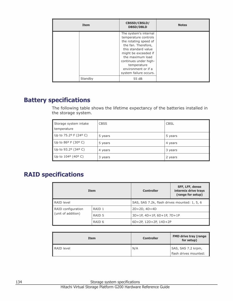
Item CBSSD/CBSLD/DBSD/DBLD Notes
The system's internaltemperature controlsthe rotating speed ofthe fan. Therefore,this standard value
might be exceeded ifthe maximum load
continues under high-temperature
environment or if asystem failure occurs.
Standby 55 dB
Battery specificationsThe following table shows the lifetime expectancy of the batteries installed inthe storage system.
Storage system intake
temperature
CBSS CBSL
Up to 75.2º F (24º C) 5 years 5 years
Up to 86º F (30º C) 5 years 4 years
Up to 93.2º (34º C) 4 years 3 years
Up to 104º (40º C) 3 years 2 years
RAID specifications
Item ControllerSFF, LFF, dense
intermix drive trays(range for setup)
RAID level SAS, SAS 7.2k, flash drives mounted: 1, 5, 6
RAID configuration(unit of addition)
RAID 1 2D+2D, 4D+4D
RAID 5 3D+1P, 4D+1P, 6D+1P, 7D+1P
RAID 6 6D+2P, 12D+2P, 14D+2P
Item Controller FMD drive tray (rangefor setup)
RAID level N/A SAS, SAS 7.2 krpm,
flash drives mounted:
134 Storage system specificationsHitachi Virtual Storage Platform G200 Hardware Reference Guide
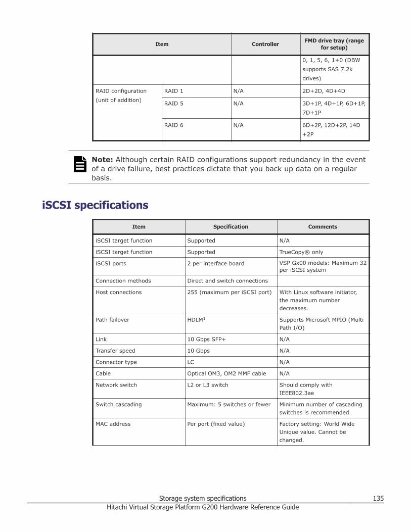
Item Controller FMD drive tray (rangefor setup)
0, 1, 5, 6, 1+0 (DBW
supports SAS 7.2k
drives)
RAID configuration
(unit of addition)
RAID 1 N/A 2D+2D, 4D+4D
RAID 5 N/A 3D+1P, 4D+1P, 6D+1P,
7D+1P
RAID 6 N/A 6D+2P, 12D+2P, 14D
+2P
Note: Although certain RAID configurations support redundancy in the eventof a drive failure, best practices dictate that you back up data on a regularbasis.
iSCSI specificationsItem Specification Comments
iSCSI target function Supported N/A
iSCSI target function Supported TrueCopy® only
iSCSI ports 2 per interface board VSP Gx00 models: Maximum 32per iSCSI system
Connection methods Direct and switch connections
Host connections 255 (maximum per iSCSI port) With Linux software initiator,the maximum numberdecreases.
Path failover HDLM1 Supports Microsoft MPIO (MultiPath I/O)
Link 10 Gbps SFP+ N/A
Transfer speed 10 Gbps N/A
Connector type LC N/A
Cable Optical OM3, OM2 MMF cable N/A
Network switch L2 or L3 switch Should comply withIEEE802.3ae
Switch cascading Maximum: 5 switches or fewer Minimum number of cascadingswitches is recommended.
MAC address Per port (fixed value) Factory setting: World WideUnique value. Cannot bechanged.
Storage system specifications 135Hitachi Virtual Storage Platform G200 Hardware Reference Guide

Item Specification Comments
Maximum transfer unit (MTU) 1,500, 4,500, 9,000 bytes(Ethernet frame)
Jumbo frame, MTU size greaterthan 1500
Link aggregation Not supported N/A
Tagged VLAN Supported N/A
IPv4 Supported N/A
IPv6 Supported Note the following precautions:• When iSCSI Port IPv6 is set
to Enabled, if the IPv6global address is set toautomatic, the address isdetermined by acquiring aprefix from an IPv6 router.
• If the IPv6 router does notexist in the network, theaddress cannot bedetermined. As a result, aniSCSI connection might bedelayed. When an iSCSIPort IPv6 is set to Enabled,verify the IPv6 router isconnected to the samenetwork, and then set IPv6global addressautomatically.
Subnet mask Supported N/A
Gateway address Supported N/A
DHCP N/A N/A
DNS N/A N/A
Ping (ICMP ECHO) Transmit,Receive
Supported N/A
IPsec2 N/A N/A
TCP port number 3260 Changeable among 1 to65,535. Observe the following ifchanging values:• The setting of the
corresponding host shouldalso be changed to log inthe new port number.
• The new port number mightconflict with other networkcommunication or befiltered on some networkequipment, preventing thestorage system fromcommunicating through thenew port number.
136 Storage system specificationsHitachi Virtual Storage Platform G200 Hardware Reference Guide

Item Specification Comments
iSCSI name Both iqn3 and eui4 types aresupported
The unique iqn value isautomatically set when a targetis made. iSCSI name isconfigurable.
Error recovery level 0 (zero) Error recovery by retrying fromhost. Does not support Level 1and Level 2.
Header digest Supported Detects header error or dataerror with iSCSIcommunication. The storagesystem follows the host's digestsetting. If digest is enabled, theperformance degrades. Theamount of the degradationdepends on factors such as hostperformance of host andtransaction pattern.
Data digest Supported
Maximum iSCSI connections atone time
255 per iSCSI port N/A
CHAP Supported Authentication: login request issent properly from host tostorage. CHAP is not supportedduring discovery session.
Mutual (2-way) CHAP Supported (not available ifconnected to Linux softwareinitiator)
Authentication: login request issent properly from host tostorage.
CHAP user registration Max 512 users per iSCSI port N/A
iSNS Supported With iSNS (name service), ahost can discover a targetwithout knowing the target's IPaddress.
Note:1. JP1, HiCommand Dynamic Link Manager. Pass switching is achieved. Not supported on
Windows Vista and Windows 7 operating systems.2. IP Security. Authentication and encryption of IP packets. The storage system does not
support IPsec.3. iqn: iSCSI Qualified Name. The iqn consists of a type identifier, "iqn," a date of domain
acquisition, a domain name, and a character string given by the individual who acquired thedomain. Example: iqn.1994-04.jp.co.hitachi:rsd.d7m.t.10020.1b000.tar
4. eui: 64-bit Extended Unique Identifier. The eui consists of a type identifier, "eui," and anASCII-coded, hexadecimal, EUI-64 identifier. Example: eui.0123456789abcdef
iSCSI standardsThe following standards apply to the management, maintenance, and iSCSIdata ports. To configure this system, use switches that comply with thefollowing standards:
Storage system specifications 137Hitachi Virtual Storage Platform G200 Hardware Reference Guide

• IEEE 802.1D STP• IEEE 802.1w RSTP• IEEE 802.3 CSMA/CD• IEEE 802.3u Fast Ethernet• IEEE 802.3z 1000 BASE-X• IEEE 802.1Q Virtual LANs• IEEE 802.3ad Dynamic LACP• IEEE 802.3ae 10 Gigabit Ethernet• RFC 768 UDP• RFC 783 TFTP• RFC 791 IP• RFC 793 TCP• RFC 1157 SNMP v1• RFC 1231 MIB II• RFC 1757 RMON• RFC 1901 SNMPv2
Regulatory complianceThis equipment has been tested and certified for compliance with thefollowing standards.
Standard Specification Mark on the product Country regulation
Electronic emissioncontrols
FCC part 15 Subpart B:2013
FCC USA and Canada
ICES-003 Issue 5:2012 ICES-003 USA and Canada
AS/NZS CISPR22:2009+A1
RCM Australia and NewZealand
TP TC 020/2011 EAC Russia, Belarus, andKazakhstan
CNS 13438 BSMI Taiwan
KN22 KC Korea
KN24 KC Korea
Electronic emissioncertifications
EN5522: 2010 CEmarking EU
EN5524: 2010 CEmarking EU
EN61000-3.2:2006+A1+A2
CEmarking EU
EN61000-3.3:2008 CEmarking EU
Safety certifications UL and CSA60950-1:2007
cTUVus USA and Canada
EN60950-1:2006+A1 TUV Germany
138 Storage system specificationsHitachi Virtual Storage Platform G200 Hardware Reference Guide

Standard Specification Mark on the product Country regulation
IEC60950-1:2005+A1 N/A All CB countries
IEC60950-1:2005+A1 S_Mark Argentina
TP TC 004/2011 EAC Russia
CNS 14336-1 BSMI Taiwan
EN60950-1:2006+A1 CEmarking EU
Radio interferencevoluntary control
VCCI V-3/2013.04 VCCI Japan
Dense intermix drive tray connection restrictionsIf a drive is inserted into a slot of a dense intermix drive tray when theinstalled number of drives exceeds 240 slots per path, the drive is blocked.
Physical SVP hardware specificationsThe following table lists the hardware specifications for the physical SVPsupplied by Hitachi Data Systems.
Caution: The physical SVP is not supported in high-temperatureenvironments. Do not operate it in locations where the temperature is 40°Cor higher.
Item Specification
Dimensions Height: 1.7 inches (43 mm)
Width: 17.2 inches (437 mm)
Depth: 14.5 inches (369 mm)
Weight: 14 lbs (6.4 kg)
Processor Celeron G1820 2.7-GHz 2M, 2C, 2T
• Cores: 2
• Instruction set: 64-bit
• SmartCache: 2 MB
• Maximum memory size: 32 GB
• Memory types: DDR3-1333, DDR3L-1333 @1.5V
Memory 8-GB RAM DDR3
Hard drive 2 TB
Network interface card x4 ports (on-board NIC) +
Storage system specifications 139Hitachi Virtual Storage Platform G200 Hardware Reference Guide
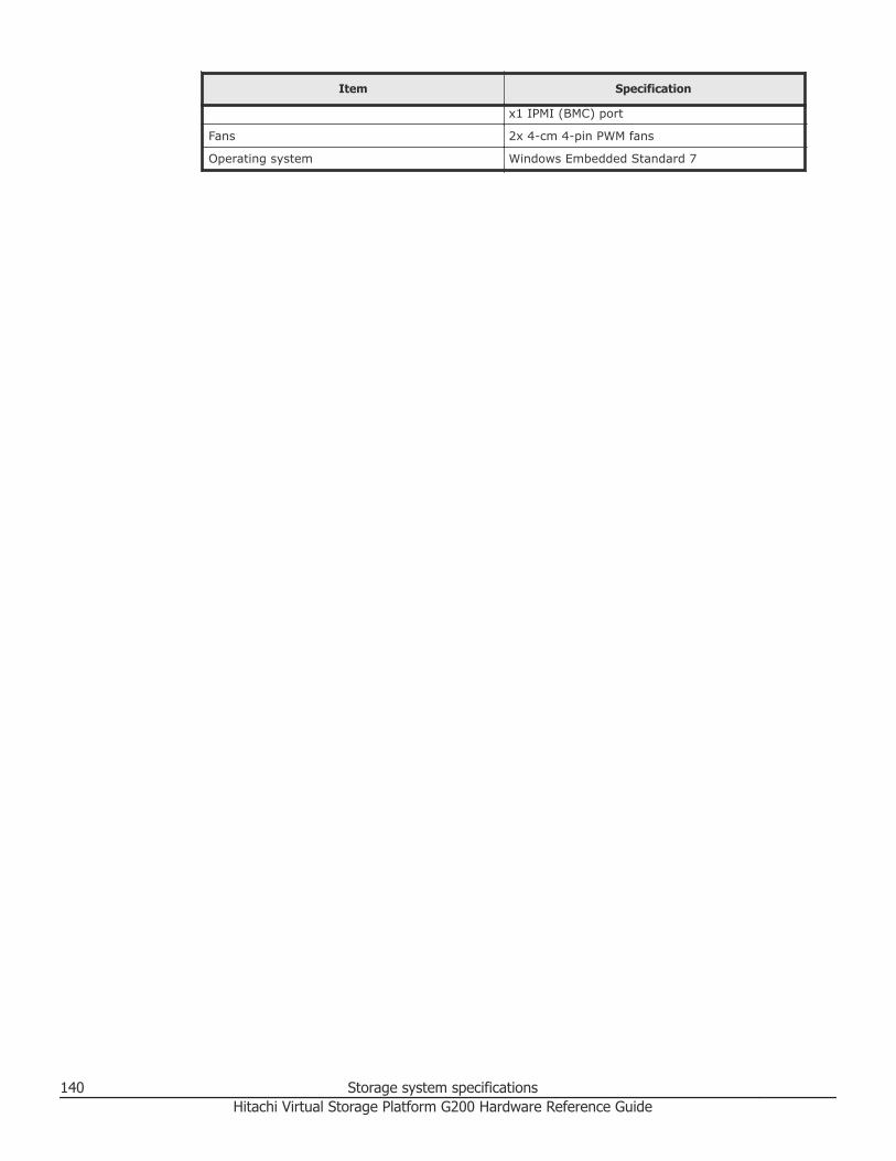
Item Specification
x1 IPMI (BMC) port
Fans 2x 4-cm 4-pin PWM fans
Operating system Windows Embedded Standard 7
140 Storage system specificationsHitachi Virtual Storage Platform G200 Hardware Reference Guide
IndexNumerics
10 Gbps iSCSI board (copper) 3410 Gbps iSCSI board (optical) 3316 Gbps Fibre Channel board 35, 3632 Gbps Fibre Channel board 358 Gbps Fibre Channel board 35
AAC
mechanical specifications 119AC power supply units
CBSL controller 39CBSS controller 39large form factor drive tray 50small form factor drive tray 50
Bback end module
LEDs and connectors 38backing up user accounts 102battery
specifications 134unit 118
bezelsCBSL controller 29CBSS controller 26dense intermix drive tray 48flash module drive tray 45large form factor drive tray 42small form factor drive tray 40
Ccables
removing 89CBSL controller 29
AC power supply unit 39CBSL controller 29front panel bezel 29rear panel 31without front panel bezel 30
CBSLD power supply unit 39
CBSS controller 26AC power supply unit 39rear panel 28with front panel bezel 26without front panel bezel 27
CBSSD power supply unit 39compliance 138configurations 20connection restrictions for dense intermix drivetray 139connections
dense intermix drive tray restrictions 139controllers
CBSL 29CBSS 26
DDC
electrical specifications 128environmental specifications 132mechanical specifications 123
DC power supply unitsCBSLD 39CBSSD 39large form factor drive tray 51small form factor drive tray 51
dense intermix drive tray 48display LEDS 49rear panel 49with front panel bezel 48
dense intermix drive tray connection restrictions139disabling user accounts 95display LEDS on dense intermix drive tray 49drive trays
dense intermix 48flash module 45large form factor 42maximum number 21small form factor 40
Index 141Hitachi Virtual Storage Platform G200 Hardware Reference Guide

Eelectrical specifications 127
DC 128environmental specifications 129
DC 132
Ffeatures 19Fibre Channel
cable removal 89flash module drive tray 45
rear panel 47with front panel bezel 45without front panel bezel 45
front end modules10 Gbps iSCSI board (copper) 3410 Gbps iSCSI board (optical 3316 Gbps Fibre Channel board 35, 3632 Gbps Fibre Channel board 358 Gbps Fibre Channel board 35
front panel bezelsCBSL controller 29CBSS controller 26dense intermix drive tray 48flash module drive tray 45large form factor drive tray 42small form factor drive tray 40
Hhardware
specifications 139
IiSCSI
cable removal 89specifications 135standards 137
LLAN blade LEDs and connectors 38large form factor drive tray 42
AC power supply unit 50DC power supply units 51rear panel 44with front panel bezel 42without bezel 43
Mmaintaining the storage system 87maximum
number of mounted drives 21
mechanical specificationsAC 119DC 123
model lists 106mounted drive trays 21
Nnumber of mounted drive trays 21
Pparts, replacement 118physical SVP
hardware specifications 139rear panel 53
power supply unitsCBSL controller 39CBSLD 39CBSS controller 39CBSSD 39
powering off the storage system 89
RRAID specifications 134rear panel of physical SVP 53rear panels
CBSL controller 31CBSS controller 28dense intermix drive tray 49flash module drive tray 47large form factor drive tray 44small form factor drive tray 42
regulatory compliance 138removing cables 89removing user accounts 99replacement parts 118
battery unit 118restoring user account information 102roles 92
SSAS cables
removing 89scalability 20setting up user accounts 93small form factor drive tray 40
AC power supply unit 50DC power supply units 51rear panel 42with front panel bezel 40without bezel 41
specificationsbattery 134electrical 127electrical (DC) 128
142 IndexHitachi Virtual Storage Platform G200 Hardware Reference Guide

environmental 129environmental (DC) 132hardware 139iSCSI 135mechanical (DC) 123RAID 134storage system 105
standards for iSCSI 137storage system
maintenance 87power off 89regulatory compliance 138specifications 105storing 88
storage system controllersCBSL 29CBSS 26
storing the storage system 88supported configurations 20System Option Modes 56
Uuser administration 91
Index 143Hitachi Virtual Storage Platform G200 Hardware Reference Guide

144 IndexHitachi Virtual Storage Platform G200 Hardware Reference Guide

Hitachi Virtual Storage Platform G200 Hardware Reference Guide

Hitachi Data Systems
Corporate Headquarters2845 Lafayette StreetSanta Clara, California 95050-2639U.S.A.www.hds.com
Regional Contact Information
Americas+1 408 970 [email protected]
Europe, Middle East, and Africa+44 (0) 1753 [email protected]
Asia Pacific+852 3189 [email protected]
Contact Uswww.hds.com/en-us/contact.html
MK-94HM8020-07
October 2016