hmtsuzlle, alubumd - nasa · nasa-george c. marshall space flight center technical memorandum...
TRANSCRIPT

I - ~
L
' NASA TECHNICAL MEMORdNDUM
I . N.4S.4 TM X-53546
December 5, 1966
A P O R T A B L E D I F F E R E N T I A L B A L L G A U G E T O M E A S U R E T H E I N T E R N A L F L A R E A N G L E O F M C 1 4 6 F L A R E D T U B I N G By David Cleghorn, William A. Wall, and J D Bennight
Manufacturing Engineering Laboratory
NASA
George C. Murshdll Spuce Flight Center, Hmtsuzlle, Alubumd
https://ntrs.nasa.gov/search.jsp?R=19670009723 2018-07-16T06:15:30+00:00Z
TECHNICAL MEMORANDUM X-53 546
A PORTABLE DIFFERENTIAL BALL GAUGE TO MEASURE THE INTERNAL FLARE ANGLE
OF MC146 FLARED TUBING
David Cleghorn William A. Wall J D Bennight
George C. Marshall Space Flight Center Huntsville, Alabama
A B STRA CT
The internal angle of MC 146 Revision D flared tubing is specified as 74" f 1Q' . This angle is critical for correct mating with the male flare fitting. A considerable amount of effort has been expended for quality control purposes to measure this angle by a plaster o r plastic cast method. Techniques to meas- ure this angle are usually time consuming and costly.
This document describes a portable, differential ball gauge developed by the Manufacturing Engineering Laboratory to measure the internal flare angle accurately and speedily. The operational theory and pertinent rnathematical der- ivations are included herein to demonstrate the principles of design of the Internal Flare Angle Gauge MR&T-sk-872. Potential e r r o r sources are discussed in order to evaluate their theoretical and practical impact on total accuracy. Tables and charts are included to short cut the design t ime of future ball gauges.
It is concluded that the differential ball gauge concept is a practical shop and inspection instrument which will quickly determine the average internal tube flare angle without waiting or relying heavily on operator judgement.
NASA-GEORGE C. MARSHALL SPACE FUGHT CENTER

. NASA-GEORGE C. MARSHALL SPACE FLIGHT CENTER
TECHNICAL MEMORANDUM x-53546
A PORTABLE DIFFERENTIAL BALL GAUGE TO MEASURE THE INTERNAL FLARE ANGLE
OF MC146 FLARED TUBING
BY
David Cleghorn William A. Wall
J D Bennight
MANUFACTURING RESEARCH AND TECHNOLOGY DIVISION MANUFACTURING ENGINEERING LABORATORY RESEARCH AND DEVELOPMENT OPERATIONS
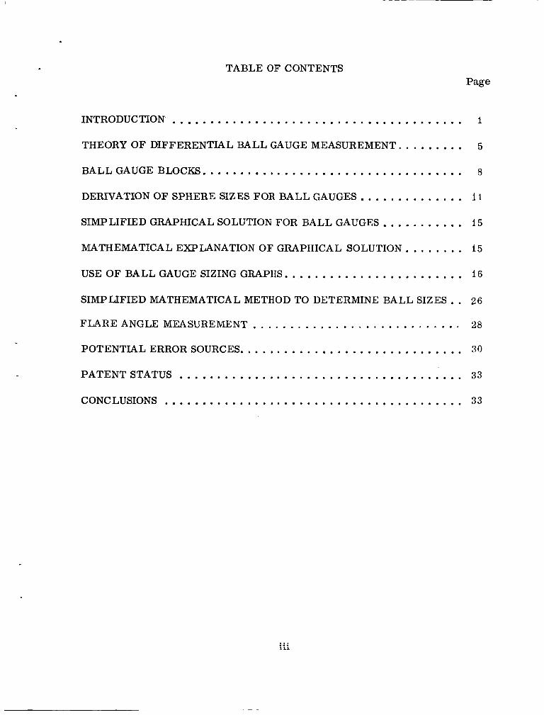
TABLEOFCONTENTS Page
INTRODUCTION ....................................... 1
THEORY OF DIFFERENTIAL BALL GAUGE MEASUREMENT . . . . . . . . . 5
BALLGAUGEBLOCKS ................................... 8
DERIVATION OF SPHERE SIZES FOR BALL GAUGES . . . . . . . . . . . . . . 11
SIMPLIFIED GRAPHICAL SOLUTION FOR BALL GAUGES . . . . . . . . . . . 15
MATHEMATICAL EXPLANATION OF GRAPHICAL SOLUTION . . . . . . . . 15
USE O F BALL GAUGE SIZING GRAPHS ........................ 16
SIMPLIFIED MATHEMATICAL METHOD TO DETERMINE BALL SIZES . . 26
FLARE ANGLE MEASUREMENT . . . . . . . . . . . . . . . . . . . . . . . . . . . . 28
POTENTIALERRORSOURCES .............................. 30
PATENTSTATUS ...................................... 33
CONCLUSIONS ........................................ 33

LIST OF ILLUSTRATIONS
Figure Title Page
I. Marshall Tube Flare Specification MC 146 . . . . . . . . . . . . . 2
2. Precision Ball Method of Determining the Internal Flare Angle . . . . . . . . . . . . . . . . . . . . . . . . . . . . . . . . . . 3
3. Flare Angle Gauge MR&T-sk-872 . . . . . . . . . . . . . . . . . . . 4
6 4. Differential Ball Gauge Pictorial Diagram . . . . . . . . . . . . . .
8 5. MR&T-sk-872 Differential Ball Gauge Ki t . . . . . . . . . . . . .
6. Points of Minimum and Maximum Tubing Wall Thickness . . . . . . . . . . . . . . . . . . . . . . . . . . . . . . . . . . . 10
7. Geometric Relationships of the Internal Flare Angle . . . . . . . 12
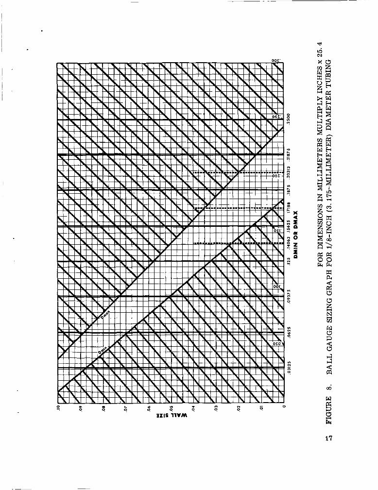
8. Ball Gauge Sizing Graph for 1/8-inch (3.175-millimeter) Diameter Tubing . . . . . . . . . . . . . . . . . . . . . . . . . . . . . . 17
9. Ball Gauge Sizing Graph for 1/4-inch (6,350-millimeter) Diameter Tubing . . . . . . . . . . . . . . . . . . . . . . . . . . . . . . 18
10. Ball Gauge Sizing Graph for 5/16-inch (7. 9375-millimeter) Diameter Tubing . . . . . . . . . . . . . . . . . . . . . . . . . . . . . . 19
11. Ball Gauge Sizing Graph for 3/8-inch (9.525-millimeter) Diameter Tubing . . . . . . . . . . . . . . . . . . . . . . . . . . . . . . 20
12. Ball Gauge Sizing Graph for 1/2-inch (12. 700-millimeter) Diameter Tubing . . . . . . . . . . . . . . . . . . . . . . . . . . . . . . 21
13. Ball Gauge Sizing Graph for 5/8-inch (15.875-millimeter) Diameter Tubing . . . . . . . . . . . . . . . . . . . . . . . . . . . . . . 22
14. Ball Gauge Sizing Graph for 3/4-inch (19. 050-millimeter) DiameterTubing . . . . . . . . . . . . . . . . . . . . . . . . . . . . . . 23
15. Ball Gauge Sizing Graph for I-inch (25.4-millimeter) Diameter Tubing . . . . . . . . . . . . . . . . . . . . . . . . . . . . . . 24
iv
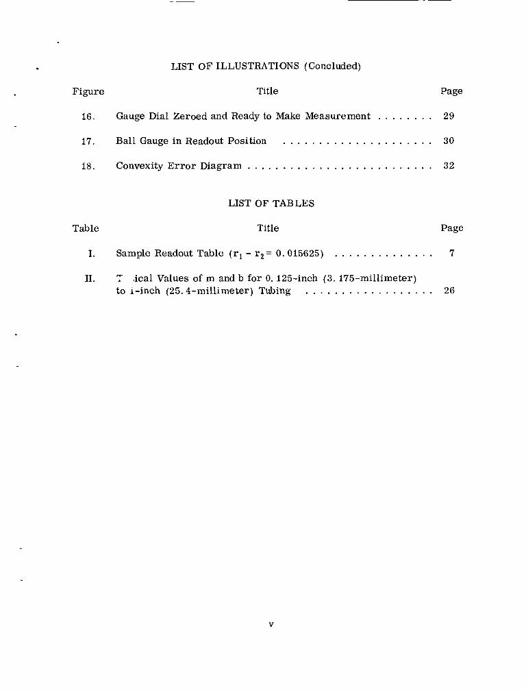
LIST OF ILLUSTRATIONS (Concluded)
Figure Title Page
16.
17.
18.
Gauge Dial Zeroed and Ready to Make Measurement . . . . . . . .
Ball Gauge in Readout Position
Convexity E r r o r Diagram . . . . . . . . . . , . . . . . . . . . . . . . . .
29
. . . . . . . . . . . . . . . . . . . . . 30
32
LIST OF TABLES
Table Title Page
I. Sample Readout Table (rl - r2 = 0.015625) . . . . . . . . . . . . . . 7
11. 7 to i-inch (25.4-millimeter) Tubing
i ca l Values of m and b for 0. 125-inch (3 . 175-millimeter) . . . . . . . . . . . . . . . . . . 26
V
TECHNICAL MEMORANDUM X- 53546
A PORTABLE D I FFERENTIAL BALL GAUGE TO MEASURE THE INTERNAL FLARE ANGLE
OF MC146 FLARED TUBING
INTRODUCTION
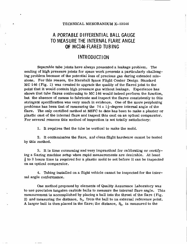
Separable tube joints have always presented a leakage problem. The sealing of high pressure joints for space work presents a particularly challeng- ing problem because of the potential loss of precious gas during extended mis- sions. Fo r this reason, the Marshall Space Flight Center Design Standard MC 146 (Fig. i) was created to upgrade the quality of the flared joint to the point that it would contain high pressure gas without leakage. Experience has shown that tube flares conforming to MC 146 would indeed perform the function, but the absence of means to fabricate and inspect the flares consistently to this stringent specification was very much in evidence. One of the more perplexing problems has been that of measuring the 74 f i i-degree internal angle of the flare. The only certified method at MSFC to date has been to make a plaster o r plastic cast of the internal flare and inspect this cast on an optical comparator. F o r several reasons this method of inspection is not totally satisfactory:
I . It requires that the tube be vertical to make the mold.
2. It contaminates the flare, and clean flight hardware cannot be tested by this method.
3. It is time consuming and very impractical for calibrating o r certify- ing a flaring machine setup when rapid measurements are desirable. At least 8 to 3 hours time is required for a plastic mold to set before it can be inspected on an optical comparator.
4. Tubing installed on a flight vehicle cannot be inspected for the inter- nal angle conformance.
One method proposed by elements of Quality Assurance Laboratory was to use precision tungsten carbide balls to measure the internal flare angle. This measurement is accomplished by placing a ball into the throat of the f lare (Fig. 2) and measuring the distance, Si, from the ball to an external reference point. A larger ball is then placed in the flare; the distance, %, is measured to the

4730-239 F E D SUP C L A S S
NONE
REFERENCE ZONES SEENOTE 7
@ REISSUED D U L 1 0 EXTENSIVE CHANGES
CONCAVITY CONVEXITY] SEE ZONE "E" SEE NOTE 7 RADIUS 'R' FLARE SEALING SURFACE
TUBE O.D.1 I
SECTION VIEW _.
TUBE I U B E 0.0. D D R R CONCEN- ROUNDNESS TtIICKNEhS 0. D.
NOMINAL T R I K Y
~ C H r MAX&UM DIA T O L RADIUS T O L
NOTES' I . THIS DESIGN 5TANDARD E b T h B L E H L S THE REQUIREMFNTS FOR THE GEOMETRIC CONFIGURATlON Of fLARED TUBE ENDh. DESIGNED FOR U S E WITH MC AND M F FLARED TUBE CONNECTORS.
1. THE f L A R E )HALL B E F R E E O F B U R H I , SHARP EDGES. CIlATTER MARKS. TOOL MARKS. EXLEISII E OXIDES. FOREIGA MATERIAL. METALLIC FLAKES. AND
5. THE R O U G H E S S O F THE BLARE S E A L M C SURF4CE. IN BOTH R A D I A L AND TANGENTIAL DIRECTIONS, SHALL NOT EXCEED l b CLA FOR ALUMINUM OR 10 C L A FUR ANY OTHER MATERIAL.
6. THE FL.4RE SEALING SURFACE PROFILE SHALL NOT EXHIBIT CONCAVITY, HOWEVER, I T M A Y HAVE A CONVEX CONFIGURATION NOT TO E X C E E D . 001
7. REFERENCE ZONES FOR DETERMINING CONCENTRICITY, ROUNDNESS AND THICKNESS CHARACTERISTICS (SEE SKETCH) ZONE "*.' 15 THE APPROXIMATE MIDPOINT OF THE FLARE SEALING SURFACE. ZONE , 'E" 15 THE APPROXIMATE MIDPOINT 06 THE EXTERNAL ANGLE SURFACE. ZONE ',C" IS APPROXIMATELY 114" FROM THE LINE O f TANGENCY OF T Y F EXTERNAL RADIUS "R ' AND THE TUBE 0. D. ZONE "E ' IS ON IHE EXTERNAL W G L E SURFACE. APPROXIMATELY AT THE LINE
THE F L A R E SEALING SURFACE (ZONE "A 'I .AND T H E TUBE 0 D. (ZONE "C"I SHALL BE CONCENTRIC WITHIN THE V4LUES LISTED IN THE TABLE. THE F L A R E SEALING SURFACE lZONE "A") SHALL BE ROUND. A5 CHECKED ON THE RADIUS
TANGENCY WITH THE EXTEI[FIAlrRADIUS "R" 8 .
A WITIIIN THE VALUES LISTED M'THE TABLE. THE CHANGE of ROUNDNESS WITHIN ANY 30. OF ARC SHALL NOT E X C E E ~ . n o w
L
A THE CHANGE O F THICKNESS. MEASURED BETWEEN THE EXTERNAL SURFACE - (ZONE "B") AND THE F L A R E SEALING SURFACE (ZONE "A'). AS CHECKED ON THE RADIUS
IN ANY 30 . O F ARC. THE F L A R E THICKp(ESS IN ZONE "E" SHALL NOT B E LESS THAN 70% OF THE NOMINAL WALL THICKNESS FOR RLUMINUM AND NOT LESS THAN 80% FOR A L L OTHER MATERIALS.
OF THE FLARE SEALINGSURFACE, SHALL NOT EXCEED THE VALUES LISTED M THE TABLE
11. n T E ~ E A X I M U M ~ I A M E T E R OF THE TUBE MEASURED APPROXIMATELY AT THE LINE OF
TANGENCY WITH RADIUS "R". SHALL NOT EXCEED T H E VALUES LISTED IN THE TABLE. 1 3 . DIMENSIONS ARE IN INCHES. 14. THIS DESIGN STANDARD Is NOT T O BE USED AS A P.4RT NUMBER
5 CUSTODIAN G E O R G E C. M A R S H A L L SPACE F L I G H T C E N T E R Huntrvillo, Alabama
DESIGN STANDARC PROCUREMENT SPECIFICATION TITLE
MC146 NONE TUBING END, FLARED, COORDINATION STATUS STANDARD DIMENSIONS FOR
SHEET I OF I MSFC
I.r .- I." I m., 1-1, ,_I
FIGURE 1. MARSHALL TUBE FLARE SPECIFICATION MC 146
2

ENCE
FIGURE 2. PRECISION BALL METHOD OF DETERMINING THE I N T ~ R N A L FLARE ANGLE
same reference point. The difference in distances (Si-S,) to the reference point, H, and the difference in diameters of the two balls dl and 4 determine the aver- age slope of the joint between the points of ball contact. Of course, precision is a function of the knowledge of the exact dimensions of the spheres and distances Si and E+. In this case the required angle A can be determined by the following formula:
- 1 A 2H Cosec -= 2 d2 - di
Solving Gaging Problems with Master Balls, Industrial Tektronics, Inc. , Technical Bulletin B-41, page 4.
3

This reporting activity was requested to design and develop a small, lightweight gauge which would utilize the ball gauge concept for measuring the tube flare internal angle. To minimize mistakes and to render the handling of the precision tungsten carbide balls easier, the decision was made to attach the spheres to either end of a stem which is properly marked to identify the correct tube size and readout table. Figure 3 pictures the finished gauge. Utilization of this differential technique vastly reduces the chances of e r r o r since it elimin- ates the need for gauge blocks, o r the like, to make up the distance from a dial indicator to the surface of the sphere. Therefore, only a standard .OOOi-inch ( .0025-millimeter) graduated dial indicator is required for readout. Since the trigonometric formula upon which this differential principle is based differs from the solution of the case illustrated in Figure 2, the following mathematical solution is offered to show how the angular readout formula for the differential ball gauge tables is derived.
4
FIGURE 3. FLARE ANGLE GAUGE MR& T-sk-872

c
l -
THEORY OF DIFFERENTIAL BALL GAUGE MEASUREMENT
Figure 4 illustrates the small sphere, in solid line, of a differential ball gauge inserted in a tube flare. It also shows the reverse operation, in dashed line, where the large sphere is in the tube flare. If the small ball is inserted in the tube flare, distance from the point of contact, A, of the ball and f la re to the actuator of the gauge is distance AM. Likewise, if the differential gauge is reversed, the distance f rom A to the gauge actuator now becomes AMI.
By inspection of Figure 4,
AM = r2 sin 8 + S + ri,
and:
+S tr2. (r1 - r2) sin 8
AMI = r2 sin 8 +
The critical dimension which finally determines the flare angle is d.
Again, by inspection of Figure 4,
d=AM1 - A M .
Substituting Equations ( I) and (2 ) into Equation ( 3 ) ,
d = + S + r 2 ] (r l -rd sin 8 [r2 sin e + [ r2 sin 8 + S + r l ]
+ S + r2 - r2 sin 8 - S- rl. ( rl - r2) sin 0 d = r2 sin 8 +
Cancelling and combining terms , the required mathematical relationship becomes :
( rl - r2) sin 8
d = - (r1 - r2)
The sample readout table, Table I, was calculated for differential ball gauges where the difference in ball radii is ( rl - r2). Distance d is the reading obtained on a dial indicator as explained later.

FLARE\
t ‘2 SIN 0
I 1 1 - ‘2
4 -I
--f-- -- -I \j- I
ACTUATOR DIAL INDICATOR
FIGURE 4. DIFFEREN’ TIAL BALL GAUGE PICTORIAL DIAGRAM
6

0 0 0 0 0 4 4 0 0 0 " " " " I ?
0 0 0 0 0 o o o o a t - I ? t - L - w
o m o m o h l h l m m * d d d d d d d d d d
m o m o m * m m w w d d d d d d d d d d
m o m o m a o o d d a 0 0 0 0 O d d d d 0 0 0 0 0 . . . . .
o m o m o h l @ J m m * 0 0 0 0 0
0 0 0 0 0 d d d d d . . . . .
k ink
I I I I I I I I I I 0 0 0 0 0 w w w w w m m m m m
0 0 0 0 0 w w w c o w m m m m m
H
m o m o m * m m w
0 0 0 0 0
d d d d d o o o o t *
. . . . * I
o m o m o " I ? w m a 0 0 0 0 0
m o m o m O-aOO.+d O d d d d d d d d d 0 0 0 0 0
d d d d d 3 0 0 0 0 . . . . . . . . . . . . . . . . . . . .
w
s Fr
D O 0 0 0 a w w Q ) w m m m m m
0 0 0 0 0 0 0 0 0 0 " " " C - P C - L - P - w w m m m m m m m m m m
I I I I I
L - w w w w " " " P P
0 0 0 0 0
o m o m o h l h l m m * a a a a a 0 0 0 0 0 0 0 0 0 0
m o m o m * m m w w m a a a a 0 0 0 0 0 0 0 0 0 0
o m o m o t - " m w a a a a m a 0 0 0 0 0 0 0 0 0 0 . . . . . . . . . . . . . . .
7

BALL GAUGE BLOCKS
Con figuration
As stated earlier, the differential ball gauge blocks consist of a small tungsten carbide and a larger tungsten carbide ball attached to either end of a metal stem (Fig. 5) . Tungsten carbide balls were selected because of their low temperature expansion coefficient, their resistance to corrosion, and their extremely hard 1 micro-inch surface finish. During fabrication, the balls a r e brazed to an oversize stem and the stem machined for .0005 inch ( .013 milli- meter) concentricity of the centerline of the stem and the spheres. Each ball gauge is then clearly marked for tube size, wall thickness range, and correct angular readout table.
BALL GAUGE DES I GN CR ITER I A
Extreme care must be exercised to ascertain that the spheres will always make contact only with the flat surface of the flare. Since a - + 10 percent varia- tion is allowable in the tube wall thickness, this fact must be considered when the large and small balls for each gauge are being sized. Originally, large scale drawings were made for a given tube size and a given wall size in order to determine these two diameters. Because of the time consumed and the inherent inaccuracy of this method, a mathematical method to accomplish this task was felt necessary. Simply stated, the problem was to determine a formula for the smallest possible sphere and the largest possible sphere which would f i t inside a given flare and at the same time rest only on the sealing surface of the flare. Formulas 9 and 21 of this document determine the required limits. Since vari- ations of the tube wall thickness affect the width of the sealing surface, these formulas are based on tube tolerances found in MSFC Design Standard MCl46, and Table 111 of MSFC-SPEC-l3IC, Figures I and 6 respectively.

OUTSIDE DIAMETER AND WALL THICKNESS TOLERANCES
Nominal dimensions (all wal l thicknesses)
Outside diameter (inch)
Permissible to le rance f r o m specified dimensions
Outside diameter Wall thickness ( inch) r a n g e ( p e r c e n t of
0 to 0. 5 incl.
O v e r 0.5 to I. 5 incl.
O v e r I. 5
/POINT OF MINIMUM WALL THICKNESS
specified dimension) Average Ovalne ss
+O. 004 0.002 f i o -0.000
+O. 005 0.003 f i o -0.000
+o. 010 0.005 f i o -0.000
ACCEPTABLE VARIATION
POINT WALL
,POINT OF WALL TH
POINT OF MAXIMUM WALL THICKNESS \
O F MINIMUM THICKNESS \
: MAXIMUM ICKNESS
UNACCEPTABLE VARIATION
FIGURE 6. POINTS O F MINIMUM AND MAXIMUM TUBING WALL THICKNESS
i o

DERIVATION OF SPHERE SIZES FOR BALL GAUGES
F o r the derivation of formulas to determine the ball diameters, refer to Figure 7.
Given: Overall diameter, Do Wall Thickness, t Outside flare diameter, D Arc Radius, R Angles e and a Segment AB and A'B' = .9t
Note: The term ''0. 9t" is an average thickness arrived at by a large sampling of MC 146 flares.
EF is parallel to AB Problem: Derive formulas expressing the diameter of smallest sphere - -
which may be tangent to AE and A'E' and the diameter of largest sphere which may be tangent to AE and A'E' using only the given.
-
Let: D1 = throat diameter AA' D = length of EF D = lengthof FB X
L Q = length of F G o r F'G' ~ - -
4 = mouth diameter EE'
D4 = length of BB' D = length of B'Q'
D = length of A' Q ' S
r
Determination of Dmin
D = diameter of smallest sphere which may be tangent t o m and A'E' . Since acute angles whose corresponding sides are mutually perpendicular are equal,
min
Angle HAA' = SEE' = angle 8 ;
Angle EFG = BCD = angle a;
D = Di sec e . min
4 4 L L
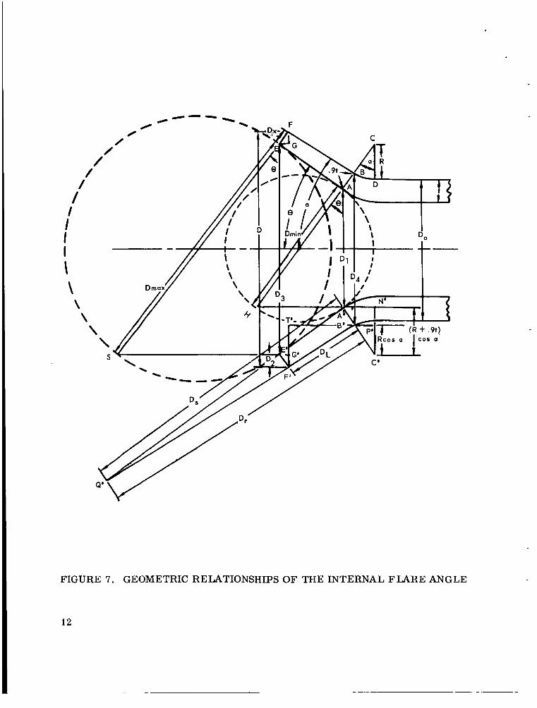
FIGURE 7. GEOMETRIC RELATIONSHIPS OF THE INTERNAL FLARE ANGLE
12
F
By inspection,
Di = Do +2R - 2C'N'
but C'N' = ( R + .9T) cos a.
Substituting the right side of ( 7) into (6) , we find :
Di = DO +2R - 2(R+. 9T) Cos a.
Substituting the right side of ( 8) into (5 ) , we find:
D = [ D o + 2 R - 2 ( R + . 9 T ) C o s a l s e c 9 . min
Determination of Dmax
- = diameter of largest sphere which may be tangent to AE and A'E' . max D
By inspection,
D4 = Do +2R - 2C'P' (10)
But C'P' = R Cos a. (11)
Substituting the right side of (ii) into ( I O ) , we find :
D 4 = D O + 2 R - 2 R C o s a = D o + 2 R (1-Cosa) . ( 12)
In triangle B'T'F,
s in a = ( D;T ) ; therefore,
D - Dd D = L 2 s in a
By inspection,

Angle B'Q'A' = (8 - a)
. 9t D = s s i n ( 8 - a )
D = D c o s ( €3 - a ) . r S
I .9t( Dr - DL)
Substituting the right half of ( 14) into (15), we have
I 4 = D - 2 Q
D = . S t c o t ( 8 - a ) . (16) r
Since corresponding parts of similar triangles are proportional, in triangles B'Q'A' and F'Q'E',
r D D = X
3 = D cos a X
D = q s e c e . max
A solution is derived by assimilating the equations as follows:
1. Substitute the right half of ( 16) and ( 13) into (17) ; 2. Substitute the right half of ( 17) into ( 18) ; 3 . Substitute the right half of (18) into ( 19) ; 4. Substitute the right half of ( 19) into (20) .
The equation derived is :
D-Do-2R( I-cos a i l )
D

It can now be shown that D formula ( 9) and D min max formula (21) are
straight line formulas; thus a simplified graphical solution is possible.
SIMPLIFIED GRAPHICAL SOLUTION FOR BALL GAUGES
If wall thickness t and Dmin ( o r Dmax ) are used as coordinates in a
rectangular system, a straight line graph is formed. Thus, for any given tube size, it is possible to determine D
out the solving formulas ( 9) and (21) . ( o r D min max ) for any given wall s
MATHEMATICAL EXPLANATION OF GRAPHICAL SOLUT
ze t with-
ON
From Equation ( 9) : D = sec 8 [ Do +.2R - 2 ( R + .9 t ) (cos a) ] . min Do, R, sec 8 and cos a are all constants for any one given tube size, and t is the only variable. This equation may be rearranged in the following manner:
D = sec 8 [Do+2R - 2 (R+.9t) cos a ] min
D = s e c e [ D o + 2 R - 2 R c o s a - i . 8 t c o s a ] min
D = Do sec 8 +2R sec 0 - 2R cos a sec 8 - 1.8t cos a sec 0 min
D = (-1.8 COS a sec e ) t + (Do sec 8 + 2R sec 8 - 2R cos a sec e ) . (22)
min
The last equation is in the form y = m x + b, the graph of which is a straight line.
Likewise, equation (21) for D is : max
D-D,,-2R( 1-cos a))]} 9t (. 9t cot (e-a) = 2 s i n a
.9t cot (e - a )
15

D, Do, R, cos a, sec 0 , cos (0 -a), and sin ( 8 -a) are all constants fo r any given tube size, and t (the wall thickness) is the only variable. Equation (21) can thus be rearranged into the following form:
D-DO-2R( I-cos a ) ] 2 cos a sec 8 D = ( - i . 8 cos a sec 0 ) t + [ + D sec 8 . max 2 s i n a c o t ( 8 - a )
Equation (22) is also in the form y = mx + b, and therefore its graph is also a straight line.
As a result of this mathematical conclusion, plots of Equations (22) and (23) are included as Figures 8 through 15 for tube sizes of 1/8 to I-inch (3.175 - 25.4 millimeter) .
USE OF BALL GAUGE S IZlNG GRAPHS
Problem:
Determine the minimum diameter sphere to use with 0.25-inch( 6.35- millimeter) by 0.020-inch ( 0.508-millimeter) wall tubing.
Solution:
1. Refer to graph in Figure 9.
2. Locate the wall s ize ( in this case 0.020-inch o r 0,508-millimeter) in the left margin marked "WALL SIZE" and read straight across to the diagonal line marked I'D 'I Proceed straight down and read the answer, 0.3035 inch min' ( 7 . 7 millimeters) .
3. The number 0.3035 inch ( 7 . 7 millimeters) may now be rounded to next higher even thirty-second of an inch (0.792 millimeter). The vertical lines on the graph indicate these increments because the production of even 1/32-inch (0 . 792 millimeter) precision balls is standard.
Problem:
Determination of maximum diameter sphere to use with 0.25-inch (6.35 millimeters) by 0.020-inch ( 0.508 millimeter) wall tubing.
I -
0 m h 9 In * 0 n 0 - ? ? ? ? 9 ? ? 9 ?
3ZIE 1 l V M
0 0 In
p!
In h z 1 n z 1 0
In
h OD
7
In h
0 n
?
In N 0 ?
In
c* n 9
W
17
X
n
0
i *
w r9
d c-l c * w P; 5
R s

d 4
w

l Z l S 11VM
20
w P;

.
3Zlb 11VM
x pc c !3
21

h 0 CI 0 0 In P 9 9 9 ? 9 a 0 0. - 9 9 9
3215 1 l V M
22
w 0
M + w
H r&

X pc
m w CS 3
23
x pc
24

1. Refer to graph in Figure 9.
2. Locate the wall size (in this case 0.020 inch o r 0.508 millimeter) in the left margin marked "WALL SIZE" and advance straight across to the diagonal line marked 'ID Proceed straight down and read the answer,
0.404 inch (10.26 millimeters) . max'
3. This answer, 0.404 inch (10.26 millimeters) , may now be rounded to the next lower even 32nd (0.792 millimeter) of a n inch.
NOTE: When the graphs a r e used for 0.75-inch (19.05 millimeters) and 1-inch (25.4 millimeters) tubing, the right margin marked "WALL SIZE" is used fo r determining the diameters of the large spheres. To find the desired wall size, proceed straight across to the diagonal line marked "D
max thence straight up to read the answer. ' I and
The above example illustrates how the diameters of the two spheres used with 0.25-inch (6.35 millimeters) tubing and 0.020 (0.508 millimeters) wall ball gauges may be calculated. Although these two sphere diameters may be adjusted as indicated in step 3 of both examples, the diameter of the small sphere must always be less than the diameter of the large sphere. If pre-calcu- lated values for m and b are available, a simplified mathematical check is also easily made. An explanation of this method follows.
25
SIMPLIFIED MATHEMATICAL METHOD TO DETERMINE BALL SIZES
i 1. 89202 1.88852
I
Given: Tube size and wall size.
Find: Diameter of small sphere and/or large sphere.
Procedure: 1. In Table II below, locate m o r b across from given tube size and desired sphere.
TABLE 11. TYPICAL VALUES O F M AND b FOR 0.125-INCH TO i-INCH TUBING
Sphere
Small Large
Small Large
Small Large
Small Large
Small Large
Small Large
Small Large
Small I Large
m
1. 89202 1. 88852
1. 89202 1. 88852
1.89202 1 .88852
i. 89202 1 . 88852
i. 89202 1.88852
i .89202 i. 88852
i. 89202 1.88852
~
b
. i 801 88
.243440
.337751
.445880
.416532
.522 93 0
.501175
.600770
.665440
.820470
.824266
.975970
.988534 1.173590
i. 309937 i. 477050
I Size is given in inches with millimeters in parentheses.
26

2. Use m and b in the following formulas:
Minimum diameter of small sphere ( D
Maximum diameter of large sphere ( D
) = b - m ( .9t)
) = b - m ( I. It)
( 24)
(25)
min
rnax
Where: t = tube wall thickness in inchss.
3. D may be increased to any convenient size and D lowered to
any convenient size; but D must always be greater than D preferably
by a minimum of 0.0666 inch (I. 584 millimeter).
min rnax
max min’
This simple solution is possible because D and D min rnax may be expressed
in the form y = mx + b. For any given tube size, m and b are constant and need not be recalculated each time.
EXAMPLE I:
To determine the minimum diameter of the small sphere used with 0.25- inch (3.175 millimeters) tubing and 0.020-inch (0.508 millimeter) wall:
I. From Table 11: m = I. 89202, b = .337751
2. Using formula (23) :
Minimum Diameter of Sphere ( D ) = .337751 - I. 89202 ( .9) ( .020) min
= .337751 - I. 89202 ( .018)
= .337751 - .034056
= .303691 inch (7 .7 millimeters)
3. The answer, .303691, may now be increased to a more convenient size if desired.
EXAMPLE 2:
To determine the maximum diameter of large sphere used with 0.25-inch (3.175 millimeters) tubing and 0.020-inch (0.508 millimeter) wall:
27

I. From Table 11: m = I. 88852, b = .445880
2. Using formula (24) :
Maximum Diameter of Large Sphere ( D ) = .44588 - 1.88852( I. I) ( .020) max
=. 44588 - I. 88852 ( .022)
= .44588 - .041547
= .40433 inches (10.25 mil- limeters)
3. The answer, .40433, may now be decreased to a more convenient size if desired.
NOTE: Examples i and 2 above demonstrate how the two spheres for 0.25-inch (3.175 millimeters) tubing and 0.020-inch (0.508 millimeter) wall are calculated. Although these two sphere diameters may be adjusted as indi- cated in step 3 of both examples, the diameter of the small sphere must always be less than the diameter of the large sphere.
The product of our development was Internal F la re Angle Gauge, MSFC drawing MR&T-sk-872. Figure 3 illustrates the gauge housing which consists of the Main Block -1, Dial Indicator -2, a Gross Movement Adjustment Screw -3, ''V" Block -4, Tube Clamping Ring -5, and an assortment of Split Sleeves -6 to clamp the specimen to be measured. A sample differential Ball Gauge -7 is also pictured. The Main Block -i is made of a special tool quality aluminum to minimize warpage and weight. Clamping of the tube sample is convenient since the spring cone inside the Clamping Ring -5 is free to rotate. The Split Sleeve -6 slides into the spring cone and hand rotation of -5 quickly clamps and aligns the tube specimen.
FLARE ANGLE MEASUREMENT
For a measurement, the tube specimen is first clamped in the Main Block, and the proper differential ball gauge selected and placed in the "Vf Block with the small sphere in the tube flare. The Gross Adjustment Screw is then used to adjust the dial indicator until its hand is off the mechanical limit. The indicator is zeroed with its regular rotating dial -8 until the hand is zeroed, Figure 16. Next, the zero setting is checked by assuring that the small sphere
28

FIGURE 16. GAUGE DIAL ZEROED AND READY TO WAKE MEASUREMENT
is snug in the flare, After the check for snugness and zero, the ball gauge is reversed, Figure 17, placing the large sphere in the flare. The dial indicator will now read distance I'd. 'I To determine the flare angle, refer to the Readout Table etched on the tab of the ball gauge. A sample readout table is illustrated in Table I. The procedure should be repeated several times until a consistent reading is obtained. Usually, two o r three minutes is sufficient time to complete a measurement.
29

.
FIGURE 17. BALL GAUGE IN READOUT POSITION
POTENTIAL ERROR SOURCES
Of course, there a r e potential e r r o r sources associated with this inspec- tion approach, but most have been eliminated o r minimized through design of the gauges. Those sources minimized through design will be discussed first.
I . Source: The known diameter and roundness of the tungsten carbide spheres.
Solution: This has been minimized by specifying precision balls below 0.75 inch ( 19.05 millimeters) in diameter to 0.00001-inch (0. 000254- millimeter) tolerance and balls 0.75 inch (19.05 millimeters and above to *0.00005-inch ( 0.00127-millimeter) tolerance. The degree of readout error is
30

inversely proportional to the difference in diameters of the balls; i. e., the larger the difference of ball diameters, the more accurate the internal flare angle can be measured. Under the worst conditions with the precision spheres specified, the maximum error due to ball diameter could range from f 2 to * 7 minutes of arc depending on many parameters. bearings with the stated tolerances are available commercially.
Tungsten carbide precision ball
2. Source: The alignment of the centerline of the gauge with respect to the centerline of the tube.
Solution: This problem has been minimized by specifying that the flats of the "V" block in which the differential ball gauge rests be parallel to the center- line of the tube clamp within * 0,001 inch (0.254 millimeter) . Actually, a cer - tain amount of cocking of the ball gauge in the "V" block can be tolerated. Up to I. 5 degrees of non-parallelism will not materially affect the readout. Align- ment of the tube in the gauge is a factor of the precision of the clamping means; therefore every 'precaution was taken to specify precision tube alignment for gauge MR&T-sk-872.
Measurement E r r o r Sources:
1. Source: Concentricity, eccentricity, and finish of the sealing surface of the tube flare.
Comment: Tube f lares made to MCi46 present no problem due to the above listed factors. The allowable eccentricity, concentricity and sealing surface finish of MCi46 precludes a smooth, uniform sealing surface. A slight pressure on the ball gauge should be sufficient to seat the differential gauge in the flare adequately.
2. Source: Convexity of the tube flare sealing surface. MC146 allows + 0.001-inch (0.0254- millimeter) convexity and zero-inch concavity of the sealing surface.
Comment: Convexity of the sealing surface is potentially the greatest source of readout e r ror . MC146, Figure 18 pictures a flare with dashed convex- ity. Further, MCi46 states that "The flare sealing surface shall not exhibit concave areas, but may have a convex configuration of a concentric nature not to exceed 0. 001 as indicated in drawing. Close inspection of triangle AOB will show that side AB is the e r r o r introduced into the dial indicator reading '7df? i f the small ball makes contact at 0 on the sealing surface and the large ball makes contact at F. The e r r o r distance introduced by the convexity would be:
31

FIGURE 18. CONVEXITY ERROR DIAGRAM
Error distance = ( Convexity) ( s in 8 )
Internal f lare angle 2 where: B =
r

Of course, the smaller the maximum convexity of the sealing surface, the less the probability of e r r o r . Also, if the amount of convexity were the same at the two points of contact, such as points D and E in Figure 18, the readout e r r o r caused by the convexity of the sealing surface would be zero because of cancel- lation. Thus, to minimize readout e r ro r due to convexity of the sealing surface, the balls should be sized to make contact as near the ends of the sealing surface as possible. A check of a large sampling of flares indicated that the probabil- ity of a large e r r o r caused by the convexity of the sealing surface is very re- mote. A maximum of f 3 to f 7 minutes of flare angle arc would normally be sufficient allowance for convexity error in a borderline case.
ACCURACY
Based on experience and probability factors, it is estimated that total angular readout e r r o r for ball gauges sized to a specific tube size and wall thick- ness would range from 0 to f 7 minutes of arc. On the other hand, ball gauges sized f o r a specific tube size and range of wall thicknesses present a probabil- ity of e r r o r ranging from 0 to f 12 minutes of arc. It then becomes obvious that a decision based on cost of additional gauges versus accuracy is a definite application consideration.
PATENT STATUS
A joint patent 011 gauges MR&T-sk-774 and MR&T-sk-872, a second generation design, has been applied f o r by Mr. W. A. Wall and Mr . N. D. Elder of the Marshall Space Flight Center.
CONCLUSIONS
The differential ball gauge method of measuring the internal flare angle of an MC146 flare is concluded to be a valid method. Speed, accuracy, reliabil- ity, maintainability and simplicity of this gauge renders it a reliable, workable, shop type, measuring instrument. Repeatability of the reading from gauge to gauge is an outstanding feature. It has been proved that the same reading, with- in reason,. may be obtained on any gauge manufactured ot the same tolerances as gauge MR&T-sk-872. In addition, this gauge is portable and can make equally accurate readings in the field o r on the bench. Of importance, frequent C a l i - bration is not required.
33

NASA T M X-53546 A PPROVA L December 5, 1966
A PORTABLE DIFFERENTIAL BALL GAUGE TO MEASURE TlIE INTEHNAL FLARE ANGLE OF MC146 FLARED TUBING
By David Clcghorn, William A. Wall, and J D Uennight
The information in this report has been reviewed for security classifica- tion. Energy Commission programs has been made by the MSFC Security Classifica- tion Officer.
Review of any information concerning Department of Defense or Atomic
This report , in its entirety, has been determined to be unclassified.
This report has' also been reviewed and approved for technical accuracy.
J"D BENNIG- Chief, Experimental Electronics Develop men t Branch
/ J. P. ORR Chief, Mnnufacturing Research & Technology Division
,, I
I / ' 4 I
W. R. KUERS Director, Manufacturing Engineering La11 oratory
34
.