holistic solutions for environmental compliance - … · holistic solutions for environmental...
TRANSCRIPT
1 © Wärtsilä Emission presentation, Cimac Oslo 27 January 2010 Göran Hellén 1/34
Holistic Solutions for Environmental Compliance27 January 2010
Göran HellénSenior Manager, Marine Regulations and Engine Affairs
Wärtsilä Industrial OperationsProduct Centre Ecotech
2 © Wärtsilä Emission presentation Cimac Oslo 27 January 2010 Göran Hellén 2/34
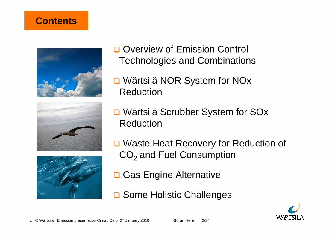
� Overview of Emission Control Technologies and Combinations
� Wärtsilä NOR System for NOxReduction
� Wärtsilä Scrubber System for SOxReduction
� Waste Heat Recovery for Reduction of CO2 and Fuel Consumption
� Gas Engine Alternative
� Some Holistic Challenges
Contents

3 © Wärtsilä Emission presentation Cimac Oslo 27 January 2010 Göran Hellén 3/34
� Overview of Emission Control Technologies and Combinations
Contents
4 © Wärtsilä Emission presentation Cimac Oslo 27 January 2010 Göran Hellén 4/34
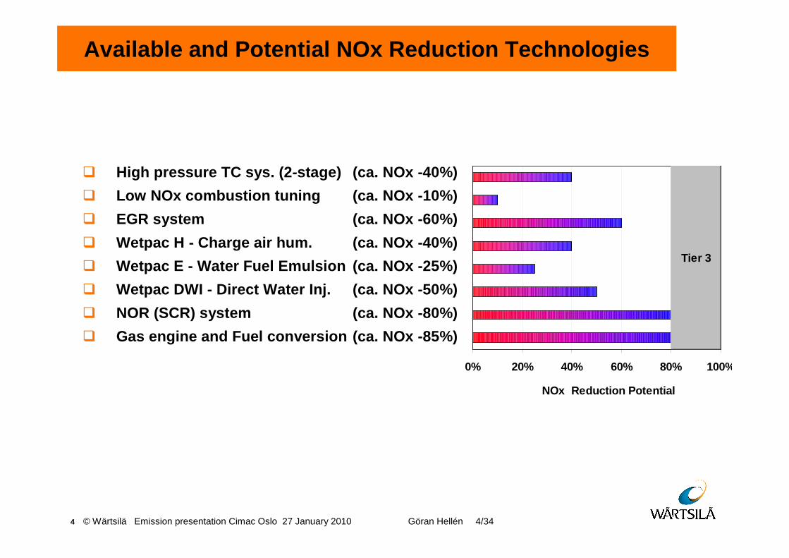
Available and Potential NOx Reduction Technologies
NOx Reduction Potential
0% 20% 40% 60% 80% 100%
Tier 3
� High pressure TC sys. (2-stage) (ca. NOx -40%)
� Low NOx combustion tuning (ca. NOx -10%)
� EGR system (ca. NOx -60%)
� Wetpac H - Charge air hum. (ca. NOx -40%)
� Wetpac E - Water Fuel Emulsion (ca. NOx -25%)
� Wetpac DWI - Direct Water Inj. (ca. NOx -50%)
� NOR (SCR) system (ca. NOx -80%)
� Gas engine and Fuel conversion (ca. NOx -85%)
5 © Wärtsilä Emission presentation 11 December 2009 Göran Hellén 5/31
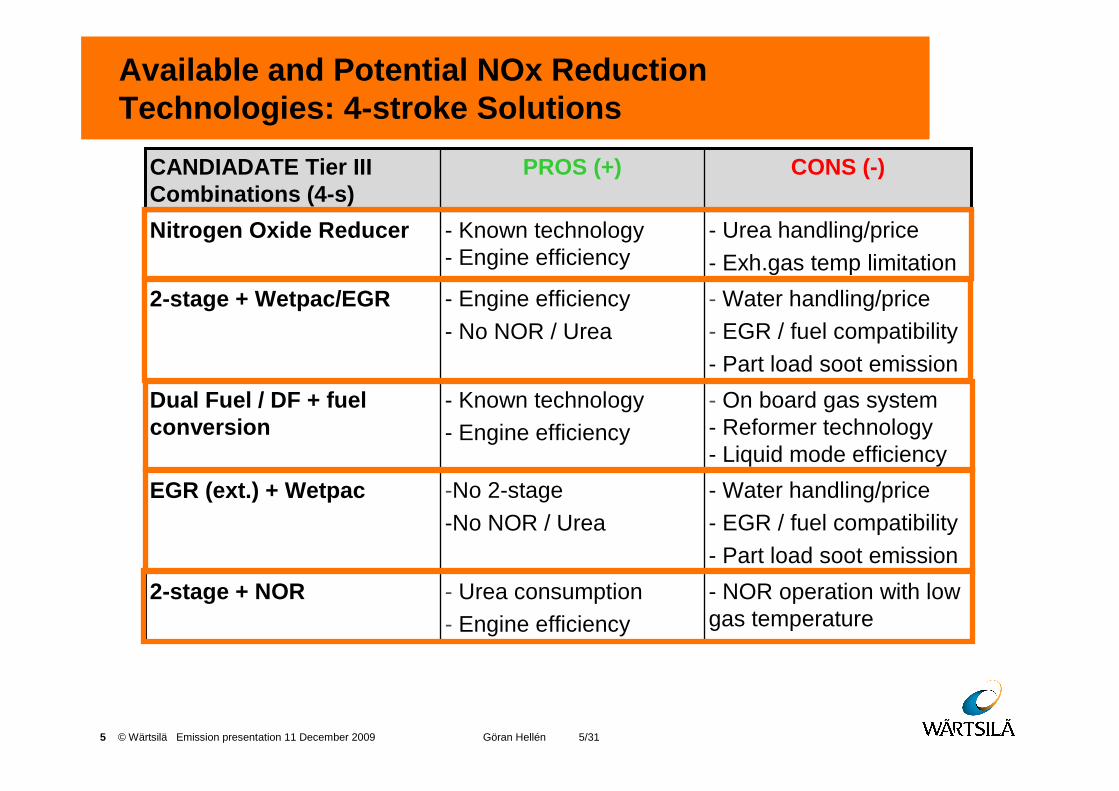
Available and Potential NOx Reduction Technologies: 4-stroke Solutions
- NOR operation with low gas temperature
- Urea consumption- Engine efficiency
2-stage + NOR
- Water handling/price- EGR / fuel compatibility- Part load soot emission
-No 2-stage -No NOR / Urea
EGR (ext.) + Wetpac
- On board gas system - Reformer technology - Liquid mode efficiency
- Known technology- Engine efficiency
Dual Fuel / DF + fuel conversion
- Water handling/price- EGR / fuel compatibility- Part load soot emission
- Engine efficiency- No NOR / Urea
2-stage + Wetpac/EGR
- Urea handling/price- Exh.gas temp limitation
- Known technology - Engine efficiency
Nitrogen Oxide Reducer
CONS (-)PROS (+)CANDIADATE Tier III Combinations (4-s)
6 © Wärtsilä Emission presentation 11 December 2009 Göran Hellén 6/31
� Wärtsilä NOR System for NOxReduction
Contents
7 © Wärtsilä Emission presentation 11 December 2009 Göran Hellén 7/31
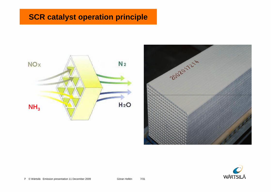
SCR catalyst operation principle
NH3
8 © Wärtsilä Emission presentation 11 December 2009 Göran Hellén 8/31
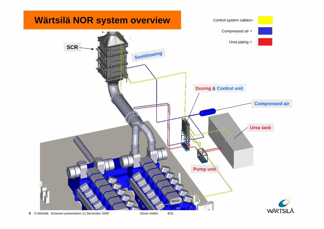
Wärtsilä NOR system overview
SCR
Urea tank
Compressed air
Pump unit
Dosing & Control unit
Control system cables=
Compressed air =
Urea piping =
Sootblowing
Wecs
9 © Wärtsilä Emission presentation 11 December 2009 Göran Hellén 9/31
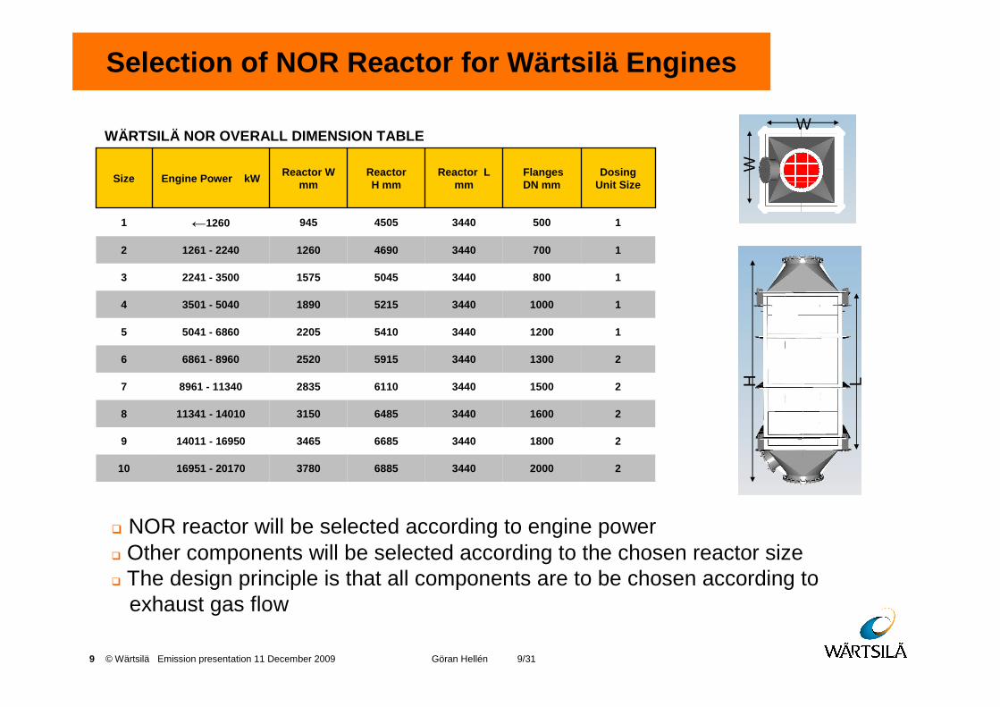
Selection of NOR Reactor for Wärtsilä Engines
� NOR reactor will be selected according to engine power� Other components will be selected according to the chosen reactor size� The design principle is that all components are to be chosen according to
exhaust gas flow
2200034406885378016951 - 2017010
2180034406685346514011 - 169509
2160034406485315011341 - 140108
215003440611028358961 - 113407
213003440591525206861 - 89606
112003440541022055041 - 68605
110003440521518903501 - 50404
18003440504515752241 - 35003
17003440469012601261 - 22402
150034404505945←12601
Dosing Unit Size
Flanges DN mm
Reactor L mm
ReactorH mm
Reactor W mmEngine Power kWSize
WÄRTSILÄ NOR OVERALL DIMENSION TABLEW
W
W
WH L

10 © Wärtsilä Emission presentation 11 December 2009 Göran Hellén 10/31
Wärtsilä NOR Performance
� High activity over a wide temperature range
� Efficient SCR process� Durable catalyst against ageing and
erosion
� Fuels: MGO / MDO / HFO (< 1.0 % S)
� Next NOR generation can operate with high sulphur fuels for combination with scrubbers
� NOR delivery means ensuring the compatibility of the NOR system with the engine.
Operation
Typically 15-20 l/h / MWUrea consumption
NOx below IMO Tier IIINOx reduction up to 90 %
Performance
11 © Wärtsilä Emission presentation 11 December 2009 Göran Hellén 11/31
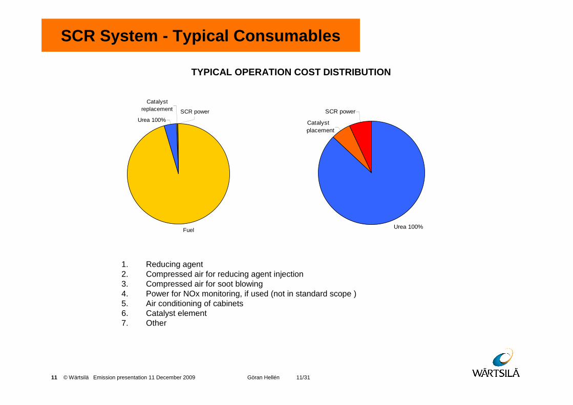
Fuel
Urea 100%
Catalyst replacement SCR power
Urea 100%
Catalyst replacement
SCR power
SCR System - Typical Consumables
1. Reducing agent2. Compressed air for reducing agent injection3. Compressed air for soot blowing4. Power for NOx monitoring, if used (not in standard scope )5. Air conditioning of cabinets6. Catalyst element7. Other
TYPICAL OPERATION COST DISTRIBUTION
12 © Wärtsilä Emission presentation 11 December 2009 Göran Hellén 12/31
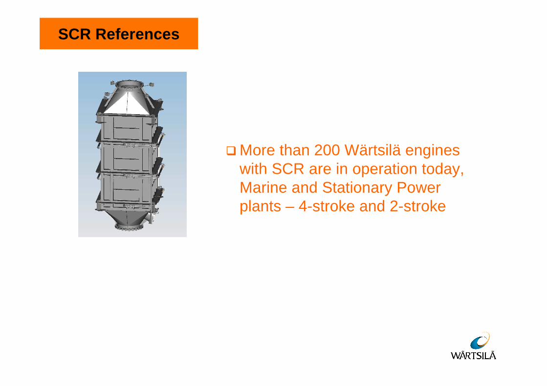
SCR References
� More than 200 Wärtsilä engineswith SCR are in operation today, Marine and Stationary Powerplants – 4-stroke and 2-stroke
13 © Wärtsilä Emission presentation 11 December 2009 Göran Hellén 13/31
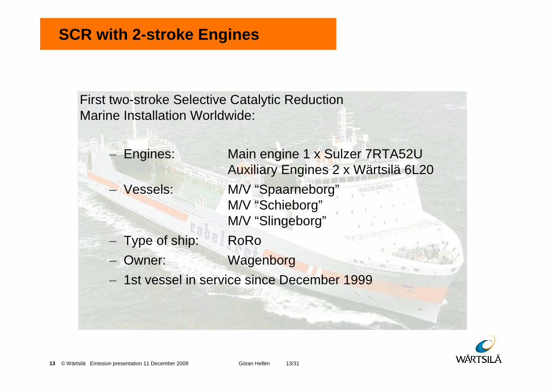
SCR with 2-stroke Engines
First two-stroke Selective Catalytic ReductionMarine Installation Worldwide:
– Engines: Main engine 1 x Sulzer 7RTA52UAuxiliary Engines 2 x Wärtsilä 6L20
– Vessels: M/V “Spaarneborg”M/V “Schieborg”M/V “Slingeborg”
– Type of ship: RoRo
– Owner: Wagenborg
– 1st vessel in service since December 1999
14 © Wärtsilä Emission presentation 11 December 2009 Göran Hellén 14/31
�Wärtsilä Scrubber System for SOxReduction
Contents
15 © Wärtsilä Emission presentation 11 December 2009 Göran Hellén 15/3115 © Wärtsilä This document is the property of Wärtsilä Corporation and shall not be copied or reproduced without the consent of the owner. © Wärtsilä
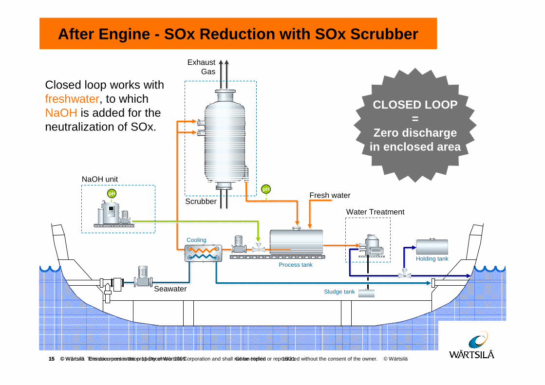
Scrubber
pHpH
NaOH unit
Fresh water
Water Treatment
Cooling
ExhaustGas
Seawater
Closed loop works with freshwater, to which NaOH is added for the neutralization of SOx.
After Engine - SOx Reduction with SOx Scrubber
CLOSED LOOP=
Zero dischargein enclosed area
Process tankHolding tank
Sludge tank
16 © Wärtsilä Emission presentation 11 December 2009 Göran Hellén 16/3116 © Wärtsilä This document is the property of Wärtsilä Corporation and shall not be copied or reproduced without the consent of the owner. © Wärtsilä
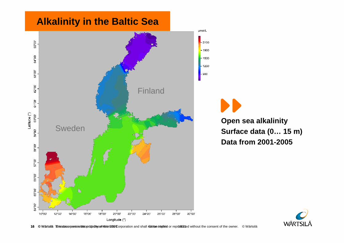
Open sea alkalinitySurface data (0… 15 m)Data from 2001-2005
Alkalinity in the Baltic Sea
Sweden
Finland
17 © Wärtsilä Emission presentation 11 December 2009 Göran Hellén 17/3117 © Wärtsilä This document is the property of Wärtsilä Corporation and shall not be copied or reproduced without the consent of the owner. © Wärtsilä
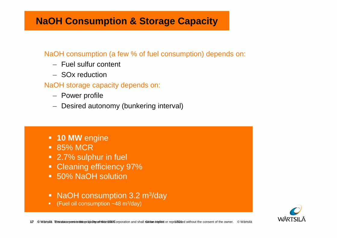
NaOH Consumption & Storage Capacity
NaOH consumption (a few % of fuel consumption) depends on:– Fuel sulfur content
– SOx reduction
NaOH storage capacity depends on:– Power profile
– Desired autonomy (bunkering interval)
� 10 MW engine� 85% MCR� 2.7% sulphur in fuel� Cleaning efficiency 97%� 50% NaOH solution
� NaOH consumption 3.2 m3/day � (Fuel oil consumption ~48 m3/day)
18 © Wärtsilä Emission presentation 11 December 2009 Göran Hellén 18/31
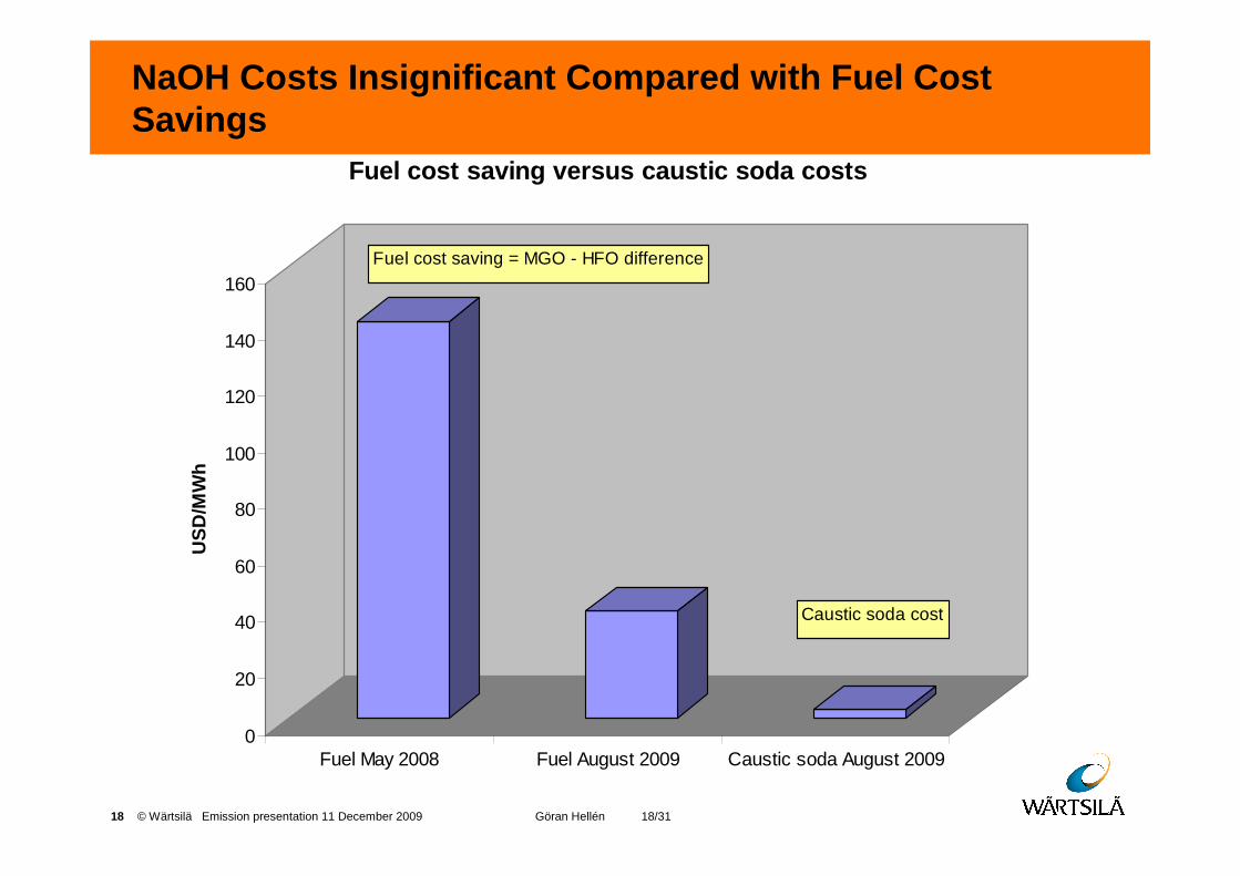
NaOH Costs Insignificant Compared with Fuel Cost Savings
0
20
40
60
80
100
120
140
160
US
D/M
Wh
Fuel May 2008 Fuel August 2009 Caustic soda August 2009
Fuel cost saving versus caustic soda costs
Fuel cost saving = MGO - HFO difference
Caustic soda cost
19 © Wärtsilä Emission presentation 11 December 2009 Göran Hellén 19/3119 © Wärtsilä This document is the property of Wärtsilä Corporation and shall not be copied or reproduced without the consent of the owner. © Wärtsilä
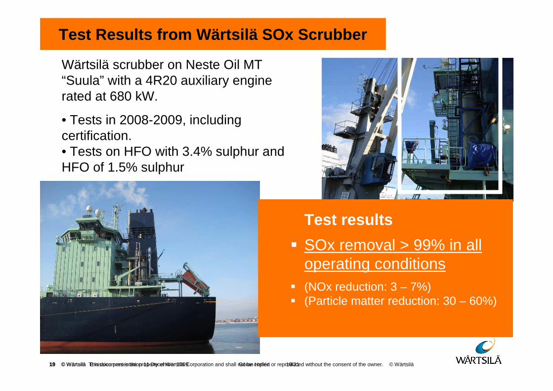
Test Results from Wärtsilä SOx Scrubber
Wärtsilä scrubber on Neste Oil MT “Suula” with a 4R20 auxiliary engine rated at 680 kW.
• Tests in 2008-2009, including certification.• Tests on HFO with 3.4% sulphur and HFO of 1.5% sulphur
Test results
� SOx removal > 99% in all operating conditions
� (NOx reduction: 3 – 7%)� (Particle matter reduction: 30 – 60%)
20 © Wärtsilä Emission presentation 11 December 2009 Göran Hellén 20/31
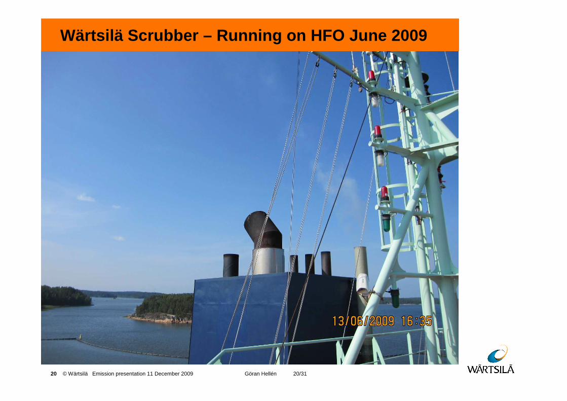
Wärtsilä Scrubber – Running on HFO June 2009
21 © Wärtsilä Emission presentation 11 December 2009 Göran Hellén 21/31
� Waste Heat Recovery for Reduction of CO2 and Fuel Consumption
Contents
22 © Wärtsilä Emission presentation 11 December 2009 Göran Hellén 22/31
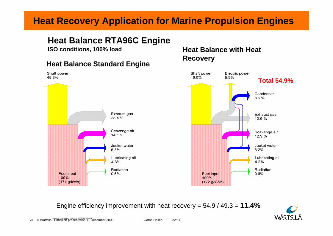
Heat Recovery Application for Marine Propulsion Eng ines
Heat recovery.ppt / 22 / 5.11.2002/ H.Schmid
Heat Balance Standard Engine
Heat Balance with Heat Recovery
Heat Balance RTA96C EngineISO conditions, 100% load
Engine efficiency improvement with heat recovery = 54.9 / 49.3 = 11.4%
Total 54.9%
23 © Wärtsilä Emission presentation 11 December 2009 Göran Hellén 23/31
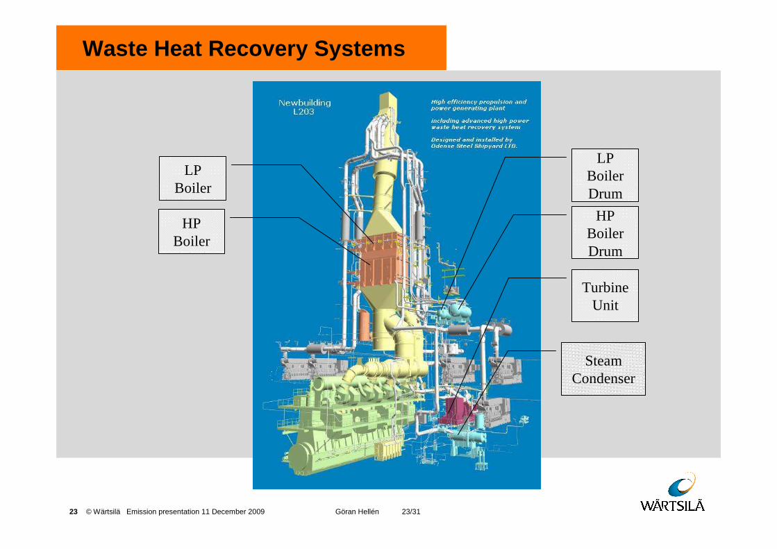
Waste Heat Recovery Systems
LP Boiler
HP Boiler
LP Boiler Drum
HP Boiler Drum
Turbine Unit
Steam Condenser
24 © Wärtsilä Emission presentation 11 December 2009 Göran Hellén 24/31
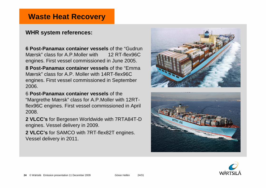
Waste Heat Recovery
WHR system references:
6 Post-Panamax container vessels of the “Gudrun Mærsk” class for A.P.Moller with 12 RT-flex96C engines. First vessel commissioned in June 2005.
8 Post-Panamax container vessels of the “Emma Mærsk” class for A.P. Moller with 14RT-flex96C engines. First vessel commissioned in September 2006.
6 Post-Panamax container vessels of the “Margrethe Mærsk” class for A.P.Moller with 12RT-flex96C engines. First vessel commissioned in April 2008.
2 VLCC’s for Bergesen Worldwide with 7RTA84T-D engines. Vessel delivery in 2009.
2 VLCC’s for SAMCO with 7RT-flex82T engines. Vessel delivery in 2011.
25 © Wärtsilä Emission presentation 11 December 2009 Göran Hellén 25/31
Engine Combined Cycles - ECCs
Wärtsilä Engine Combined Cycle Solutions on Stationa ry Power Plants
� First ECC project for Wärtsilä was in 1990 to Ringgold, 3 x 18V32GD
� Totally 10 projects under delivery, among them:
• Attock Refinery, Pakistan 9 x W18V46
• Nishat Power, Pakistan 11 x W18V46
• Nishat Chunian Power 11 x W18V46
• IGE (Monopoli), Italy 6 x W18V46 LBF
• Fri-El, Italy 4 x W18V46 LBF
• Green Energy, Italy 1 x W18V46 LBF
• Liberty Power, Pakistan 11 x W18V46
• Attock II, Pakistan
• Etc.
26 © Wärtsilä Emission presentation 11 December 2009 Göran Hellén 26/31
� Gas Engine Alternative
Contents
27 © Wärtsilä Emission presentation 11 December 2009 Göran Hellén 27/31
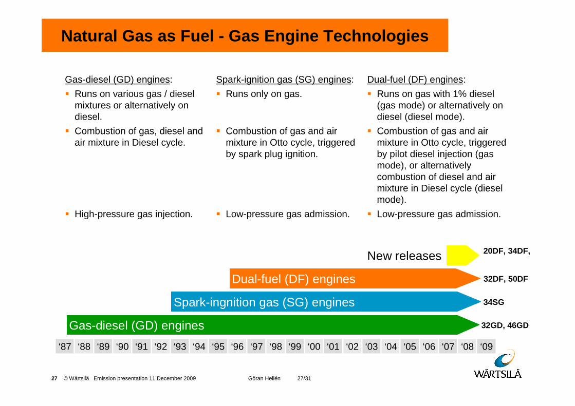
Natural Gas as Fuel - Gas Engine Technologies
Gas-diesel (GD) engines:
� Runs on various gas / diesel mixtures or alternatively on diesel.
� Combustion of gas, diesel and air mixture in Diesel cycle.
� High-pressure gas injection.
Dual-fuel (DF) engines:
� Runs on gas with 1% diesel (gas mode) or alternatively on diesel (diesel mode).
� Combustion of gas and air mixture in Otto cycle, triggered by pilot diesel injection (gas mode), or alternatively combustion of diesel and air mixture in Diesel cycle (diesel mode).
� Low-pressure gas admission.
Spark-ignition gas (SG) engines:
� Runs only on gas.
� Combustion of gas and air mixture in Otto cycle, triggered by spark plug ignition.
� Low-pressure gas admission.
Spark-ingnition gas (SG) engines 34SG
Dual-fuel (DF) engines 32DF, 50DF
Gas-diesel (GD) engines 32GD, 46GD
‘87 ‘88 ‘89 ‘90 ‘91 ‘92 ‘93 ‘94 ‘95 ‘96 ‘97 ‘98 ‘99 ‘00 ‘01 ‘02 ‘03 ‘04 ‘05 ‘06 ‘07 ‘08 ‘09
20DF, 34DF, New releases
28 © Wärtsilä Emission presentation 11 December 2009 Göran Hellén 28/31
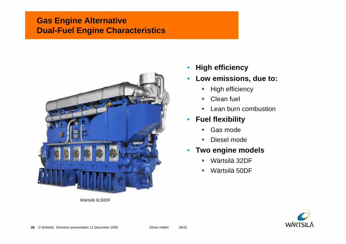
Gas Engine AlternativeDual-Fuel Engine Characteristics
• High efficiency
• Low emissions, due to:� High efficiency
� Clean fuel
� Lean burn combustion
• Fuel flexibility� Gas mode
� Diesel mode
• Two engine models� Wärtsilä 32DF
� Wärtsilä 50DF
Wärtsilä 6L50DF
29 © Wärtsilä Emission presentation 11 December 2009 Göran Hellén 29/31
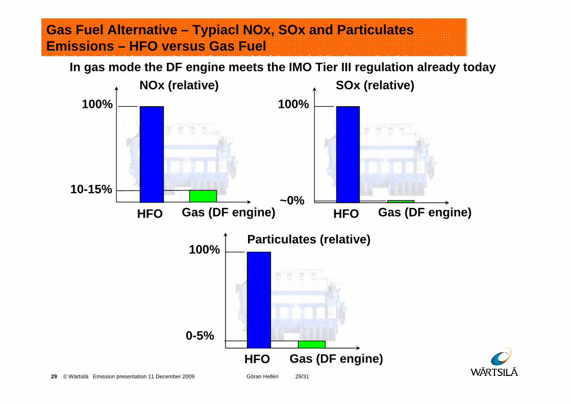
Gas (DF engine) HFO
NOx (relative)
100%
10-15%
HFO
SOx (relative)
100%
~0%Gas (DF engine)
Gas (DF engine) HFO
Particulates (relative)100%
0-5%
Gas Fuel Alternative – Typiacl NOx, SOx and ParticulatesEmissions – HFO versus Gas Fuel
In gas mode the DF engine meets the IMO Tier III regulat ion already today
30 © Wärtsilä Emission presentation 11 December 2009 Göran Hellén 30/31
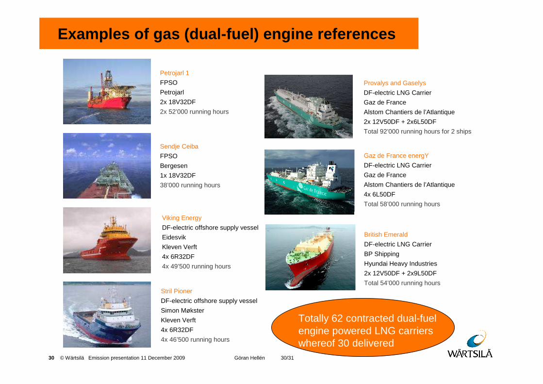
Examples of gas (dual-fuel) engine references
Petrojarl 1
FPSO
Petrojarl
2x 18V32DF
2x 52’000 running hours
Sendje Ceiba
FPSO
Bergesen
1x 18V32DF
38’000 running hours
Viking Energy
DF-electric offshore supply vessel
Eidesvik
Kleven Verft
4x 6R32DF
4x 49’500 running hours
Stril Pioner
DF-electric offshore supply vessel
Simon Møkster
Kleven Verft
4x 6R32DF
4x 46’500 running hours
Provalys and Gaselys
DF-electric LNG Carrier
Gaz de France
Alstom Chantiers de l’Atlantique
2x 12V50DF + 2x6L50DF
Total 92’000 running hours for 2 ships
Gaz de France energY
DF-electric LNG Carrier
Gaz de France
Alstom Chantiers de l’Atlantique
4x 6L50DF
Total 58’000 running hours
British Emerald
DF-electric LNG Carrier
BP Shipping
Hyundai Heavy Industries
2x 12V50DF + 2x9L50DF
Total 54’000 running hours
Totally 62 contracted dual-fuelengine powered LNG carrierswhereof 30 delivered

31 © Wärtsilä Emission presentation 11 December 2009 Göran Hellén 31/31
� Some Holistic Challenges
Contents
32 © Wärtsilä Emission presentation 11 December 2009 Göran Hellén 32/31
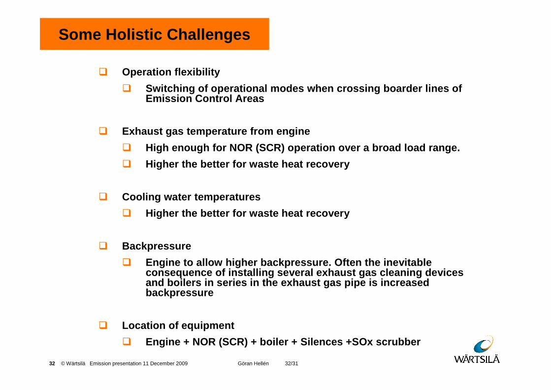
Some Holistic Challenges
� Operation flexibility
� Switching of operational modes when crossing boarde r lines of Emission Control Areas
� Exhaust gas temperature from engine
� High enough for NOR (SCR) operation over a broad lo ad range.
� Higher the better for waste heat recovery
� Cooling water temperatures
� Higher the better for waste heat recovery
� Backpressure
� Engine to allow higher backpressure. Often the inev itable consequence of installing several exhaust gas clean ing devices and boilers in series in the exhaust gas pipe is in creased backpressure
� Location of equipment
� Engine + NOR (SCR) + boiler + Silences +SOx scrubber
33 © Wärtsilä Emission presentation 11 December 2009 Göran Hellén 33/31
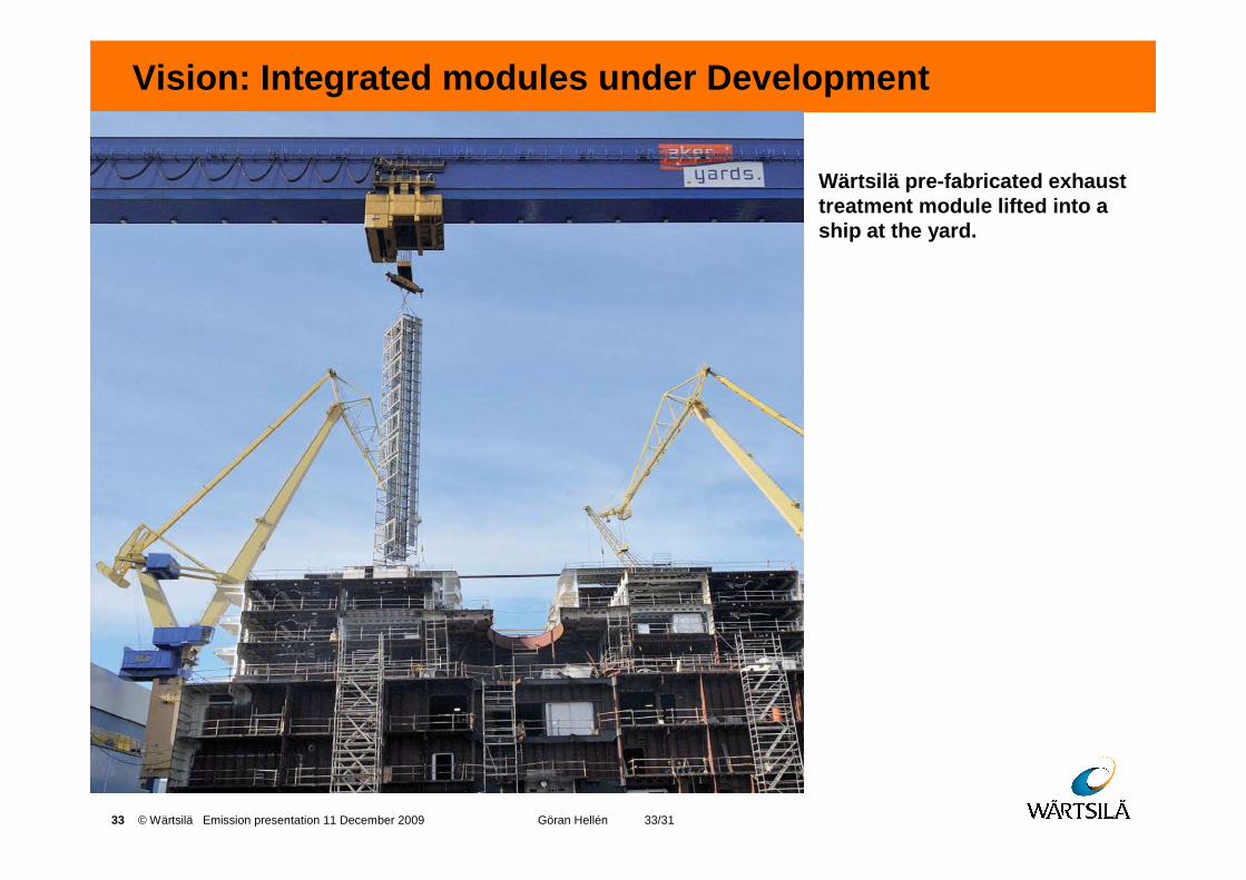
Vision: Integrated modules under Development
Wärtsilä pre-fabricated exhausttreatment module lifted into a ship at the yard.
34 © Wärtsilä Emission presentation 11 December 2009 Göran Hellén 34/31
Thank Youfor Your Attention!