honoapiʻilani highway realignment phase 1a
TRANSCRIPT
HONOAPIʻILANI HIGHWAY REALIGNMENT PHASE 1A Brian Lock, P.E., ASCE1 and Eric Matsumoto, P.E., ASCE, PCI, SEAOH2
1Associate Director, Wilson Okamoto Corporation, 1907 S. Beretania Street,
Suite 400, Honolulu, HI, 96826 2Vice President, KSF, Inc., 615 Piʻikoi Street, Suite 300, Honolulu, HI, 96814
ABSTRACT The Honoapi‘ilani Highway Realignment, Phase 1A, Future Keawe Street
Extension to Lahainaluna Road project is the first phase of the Lahaina Bypass Highway and meant to alleviate traffic congestion along the existing highway with Phase 1A targeting traffic congestion associated with the Lahainaluna School Complex.
Just before construction began, significant historical agricultural terraces were discovered in direct conflict with the highway, thereby halting design. The roadway was realigned to avoid the historical sites, requiring the re-design of concrete inverted tied-arch Kahoma Bridge. This also meant the beginning of a new environmental assessment process, including consultation with Native Hawaiians under Section 106 National Historic Preservation Act.
Kahoma bridge, which was previously straight, now required the bridge be designed on a curve. This new configuration significantly magnified the complexity of this structure. Despite the challenges, the bridge was designed and constructed to span 360’ across the stream, which we believe is the first of its type on a curve.
The project also features Lahainaluna Bridge, a 160’ grade separation bridge over the highway.
After a few years of hard work and consultation with the community, construction began in 2009 and Phase 1A was open to the public in April 2013
INTRODUCTION The Honoapi‘ilani Highway Realignment, Phase 1A, Keawe Street Extension to
Lahainaluna Road opened to the public in April 2013. The project is the first phase of the Lahaina Bypass Highway meant to alleviate traffic congestion associated with the Lahainaluna School Complex. The project features an extension of Keawe Street, ¾-mile segment of bypass highway, long span Kahoma Uka Bridge, a grade-separated Lahainaluna Road intersection with bridge, a substantial amount of earthwork, and retaining structures. The Design-Build project was constructed by Hawaiian Dredging Construction Company (HDCC) with design by Wilson Okamoto Corporation (WOC) along with KSF, Inc, Geolabs, Inc., and Cultural Surveys Hawaiʻi, Inc. (CSH) in cooperation with the State of Hawaiʻi, Department of Transportation (HDOT).
Just before construction in 2007, significant historical agricultural terraces were discovered in direct conflict with the highway, thereby halting design. The engineers
Page 1
evaluated alternative alignments to avoid the agricultural terraces allowing the project to proceed after a short delay. The re-design also meant the beginning of a new environmental assessment process, including consultation with Native Hawaiians under Section 106 National Historic Preservation Act.
The realignment triggered the re-design of Kahoma Uka Bridge. The Bridge, which was originally straight, now required a horizontal curve with a radius of 1,200 feet and superelevation. This new configuration significantly magnified the complexity of the structure. With the full cooperation and dedication of everyone involved, the re-design of Kahoma Uka Bridge expeditiously proceeded in September of 2009.
In December of 2010, work on the Kahoma Uka Bridge commenced. After two years of construction, the community was presented with a horizontally curved, 60 foot wide, 360 foot single span, low-profile, inverted tied arch bridge that neither obstructs the scenic view planes nor interferes with the stream environment below. The project also features Lahainaluna Bridge, a 130’ single span rigid frame bridge that allows Lahainaluna Road to cross over the new highway. Precast beams with parabolic soffits are utilized in this structure. At the abutments, the superstructure depth is 5’-8” while only 3’-8” at midspan. The slender superstructure with parabolic soffit a “gateway” to West Maui.
Construction of the bridge was completed at an approximate cost of $85 million.
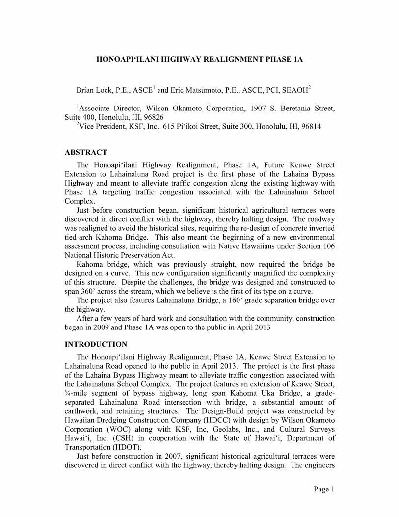
Photo 1: Plan depicting realignment of highway to avoid historical agricultural terraces.
Page 1

KAHOMA UKA BRIDGE Design Concept
During bidding, the HDCC Design-Build team conceptualized spanning across Kahoma Stream without intermediate piers utilizing a post tensioned, inverted tied-arch concrete bridge on shallow spread footings. The benefit of the single span outweighed design and construction challenges of the inverted tied-arch. During the design phase, discovery of historical agricultural terraces encompassing 30 acres conflicted with the highway, triggering re-design of Kahoma Uka Bridge. In order to respect this culturally significant site, the roadway was realigned and the bridge was designed on a horizontal curve with a radius of 1,200 feet and lengthened 360’ span. This new configuration significantly magnified the complexity of this structure.
Realigning the highway required adapting the original design, curving Kahoma Uka Bridge with a full superelevated deck. Bents, connecting the inverted arch to the deck, were aligned longitudinally with the stream, and pre-cast concrete segments were no longer uniform, each piece containing unique dimensions. The highway curve also distorted forces and displacements requiring re-design of concrete members and post-tensioning. Despite these complex challenges, the bridge was designed and constructed to span the stream.
The bridge bottom chord consists of ten lines of precast concrete plank segments that are joined together with post-tension reinforcing strands. The post-tensioned strands, which help maintain compression in the bottom chord tie, are anchored within the end blocks that are located on the abutments at each end of the bridge. The lines of precast plank segments form an inverted arch and functions as the bridge bottom chord tie to resist the tension forces that are generated in the bridge span due to flexure. In order to address the torsion created by the horizontal curvature in the bridge, the post-tensioning stresses in the planks are stepped. A greater lifting force is provided on the outside of the curve than the inside. Cast-in-place concrete beams, which run perpendicular to the length of the bridge, provide transverse stiffness to the inverted arch by bracing the individual precast segments at each end. The transverse stiffener beams also support precast concrete bents that in turn support the bridge top chord at seven locations, which are equally spaced across the length of the bridge span.
The bridge top chord consists of precast concrete deck planks and precast concrete girders that act as composite sections that are tied together through a cast-in-place concrete deck slab. The concrete girders run longitudinally with the bridge length and span between the concrete bents. The deck planks run transverse to the bridge length and span
Photo 2: Kahoma Uka Bridge (Photo credit Ed Gross Photography)
Photo 3: Kahoma Uka Bridge Precast Tub Girders
Page 1

between the concrete girders and also function as formwork for the cast-in-place concrete deck slab, which ties all of the top chord elements together.
The bridge top and bottom chord, along with the post-tension reinforcement are then anchored into the end blocks at each end of the span. The cast-in-place concrete end blocks incorporate friction pendulum bearings on top of the concrete spread footings to accommodate end block rotation and thermal expansion and contraction of the superstructure.
In the final configuration, the top chord directly supports the vehicle loads and resolves the compression strut forces in the bridge top chord. Below that, the inverted arch forms the bridge bottom chord tie with the post-tensioned reinforcing providing net compression throughout the entire bridge structure.
A total of 260 precast components were fabricated on site. This direction effectively eliminated transportation requirements of plant cast components. Transporting large precast members from the port in Kahului to Lahaina along a route containing sharp curves and tunnels would have created a severe disruption to traffic flow.
The bridge top and bottom chord construction utilized high-performance concrete mix design, with a minimum 28-day compressive strength of 8,000 psi. The concrete mix took advantage of the high-quality/high-strength aggregates available on Maui without significant cost increases. In addition, the concrete mix design for the deck slab incorporated a shrinkage-reducing admixture (SRA) that significantly reduced the shrinkage and creep, thereby reduced concrete cracking.
The bridge foundation design utilizes spread footings at both abutments. The bridge abutments are not required to resolve horizontal forces due to the inverted arch configuration since the top chord compression strut resolves the post-tension anchorage force produced in the bottom chord. The horizontal thrust forces, due to the roadway slope and thermal expansion, are transferred to the south abutment and resisted via lateral bearing on the adjacent roadway grade.
LAHAINALUNA GRADE SEPARATION BRIDGE Design Concept
For the Lahainaluna Bridge, the team developed a thin, jointless (low-maintenance), post-tensioned, cast-in-place concrete arch girder bridge on shallow foundation. The design spanned the 130’ grade separation over the new bypass highway without center piers. At the center, the arch thinned to just 3’-8” deep. The single span opened the view corridor by preventing center piers from becoming an obstruction on the highway below.
The abutments are poured neat against the rock face, which results from excavation for the new highway, and is locked into the rock substrate. The superstructure consists of multiple T-shaped girders of varying width and depth. The girder depths vary from 3’-8” at midspan to 5’-8” at the abutments located at each end of the bridge span. After the superstructure was stressed and locked with the abutments, the T-shaped girders and abutments function together as a rigid frame. An advantage of the frame’s rigidity is that the T-shaped girders resist the applied loading with a combined mechanism of “beam flexure” and “arching” to help reduce the long term deflection and to minimize abutment footing requirements.
Page 2
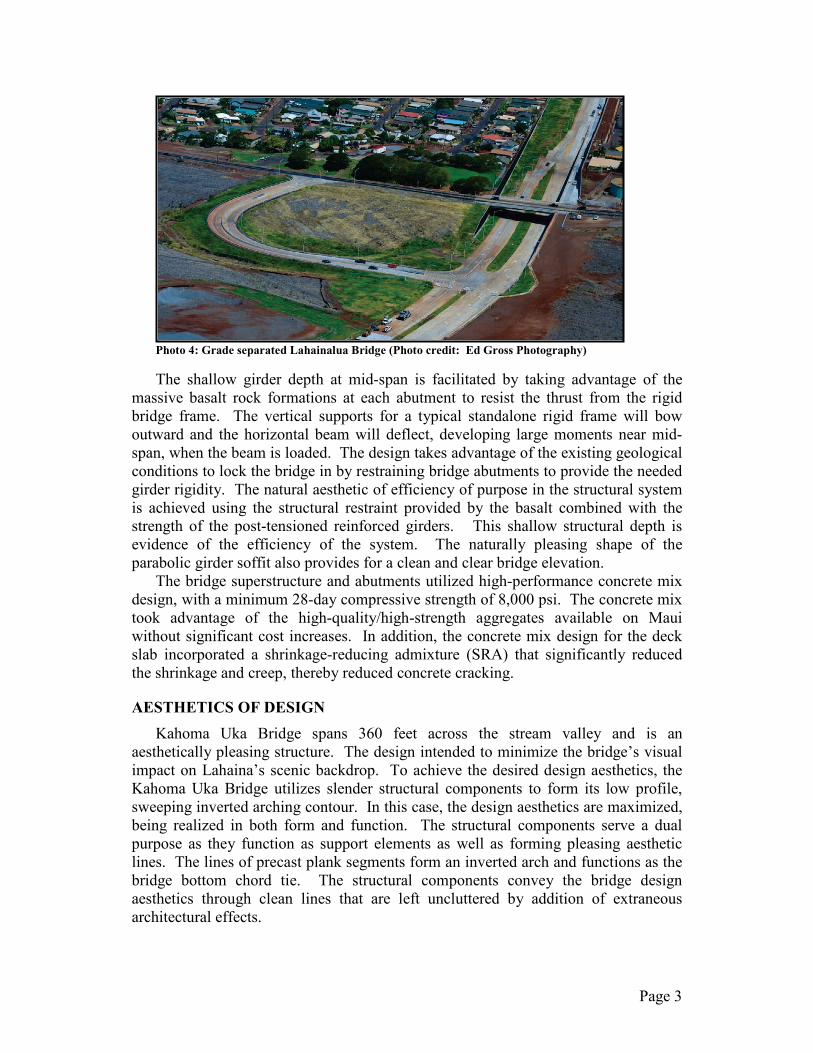
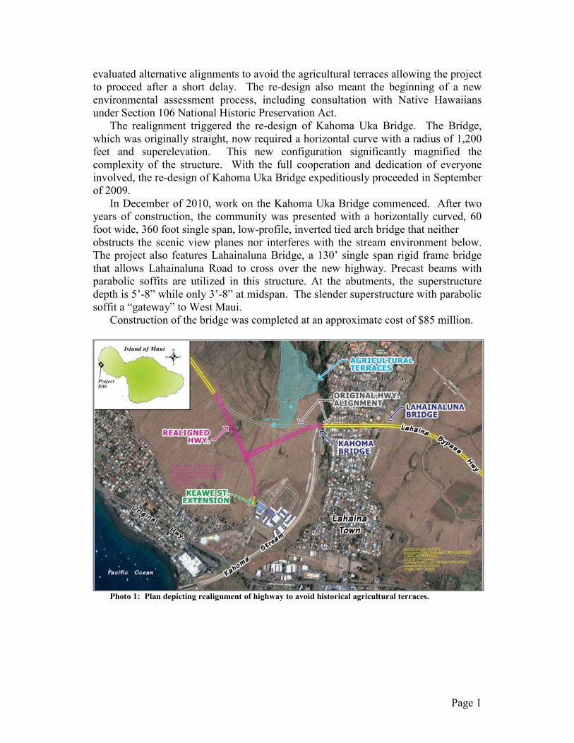
Photo 4: Grade separated Lahainalua Bridge (Photo credit: Ed Gross Photography)
The shallow girder depth at mid-span is facilitated by taking advantage of the massive basalt rock formations at each abutment to resist the thrust from the rigid bridge frame. The vertical supports for a typical standalone rigid frame will bow outward and the horizontal beam will deflect, developing large moments near mid-span, when the beam is loaded. The design takes advantage of the existing geological conditions to lock the bridge in by restraining bridge abutments to provide the needed girder rigidity. The natural aesthetic of efficiency of purpose in the structural system is achieved using the structural restraint provided by the basalt combined with the strength of the post-tensioned reinforced girders. This shallow structural depth is evidence of the efficiency of the system. The naturally pleasing shape of the parabolic girder soffit also provides for a clean and clear bridge elevation.
The bridge superstructure and abutments utilized high-performance concrete mix design, with a minimum 28-day compressive strength of 8,000 psi. The concrete mix took advantage of the high-quality/high-strength aggregates available on Maui without significant cost increases. In addition, the concrete mix design for the deck slab incorporated a shrinkage-reducing admixture (SRA) that significantly reduced the shrinkage and creep, thereby reduced concrete cracking.
AESTHETICS OF DESIGN Kahoma Uka Bridge spans 360 feet across the stream valley and is an
aesthetically pleasing structure. The design intended to minimize the bridge’s visual impact on Lahaina’s scenic backdrop. To achieve the desired design aesthetics, the Kahoma Uka Bridge utilizes slender structural components to form its low profile, sweeping inverted arching contour. In this case, the design aesthetics are maximized, being realized in both form and function. The structural components serve a dual purpose as they function as support elements as well as forming pleasing aesthetic lines. The lines of precast plank segments form an inverted arch and functions as the bridge bottom chord tie. The structural components convey the bridge design aesthetics through clean lines that are left uncluttered by addition of extraneous architectural effects.
Page 3
The inverted arch bridge structure is a hybrid solution for the required 360-foot single span, which falls in-between the span ranges for economical concrete bridge structures. For spans of up to 240 feet, segmental precast and post-tensioned concrete I-girders typically provide an economical solution. For span in excess of 500 feet, cable stay segmental concrete bridges typically provide an economical solution. In this case, the design of the inverted arch bridge evolved from a hybrid of design principles taken from each of those bridge schemes to provide a cost-efficient single span bridge solution to span 360 feet across Kahoma Stream without intermediate supports.
The slender features of the Kahoma Uka Bridge are also carried over into the top and bottom chord structural elements. From an elevation perspective, the edge of the concrete deck appears as a light structure in profile with minimal visual impact before transitioning back to the precast girders. The bottom chord also maintains a low profile across the length of the inverted tied-arch. The use of high-strength, high-performance concrete minimizes the required element thickness.
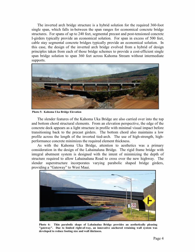
As with the Kahoma Uka Bridge, attention to aesthetics was a primary consideration in the design of the Lahainaluna Bridge. The rigid frame bridge with integral abutment system is designed with the intent of minimizing the depth of structure required to allow Lahainaluna Road to cross over the new highway. The slender superstructure incorporates varying parabolic shaped bridge girders, providing a “Gateway” to West Maui.
Photo 5: Kahoma Uka Bridge Elevation
Photo 6: Thin parabolic shape of Lahainalua Bridge provides an aesthetically pleasing "gateway". Due to limited right-of-way, an innovative anchored retaining wall system was developed to reduce footing size and wall thickness.
Page 4
EXPEDIENCY OF DESIGN AND CONSTRUCTION AND MITIGATION OF IMPACTS TO RESIDENTS
Highway construction projects typically have a multitude of impacts on residents that are located along the affected highway as well as those who utilize the roadways that are affected by construction activities. It is therefore obvious that minimizing the construction timeline minimizes the impacts to residents as well as others that may be adversely affected by construction activities. Expediency in design and construction helps condense the overall project timeline and directly helps to mitigate the impacts to those affected by the project. The contractor and the design team were able to take full advantage of the Design-Build delivery strategy to incorporate materials, means, and methods to expedite construction.
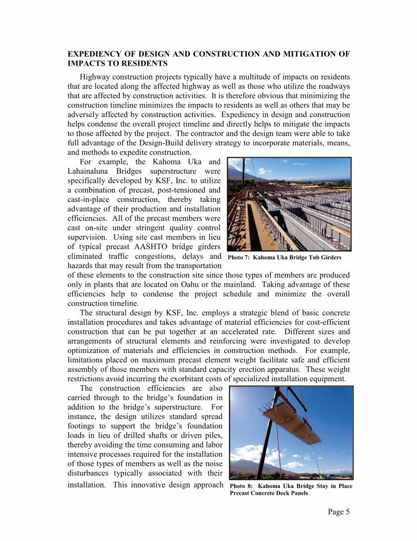
For example, the Kahoma Uka and Lahainaluna Bridges superstructure were specifically developed by KSF, Inc. to utilize a combination of precast, post-tensioned and cast-in-place construction, thereby taking advantage of their production and installation efficiencies. All of the precast members were cast on-site under stringent quality control supervision. Using site cast members in lieu of typical precast AASHTO bridge girders eliminated traffic congestions, delays and hazards that may result from the transportation of these elements to the construction site since those types of members are produced only in plants that are located on Oahu or the mainland. Taking advantage of these efficiencies help to condense the project schedule and minimize the overall construction timeline.
The structural design by KSF, Inc. employs a strategic blend of basic concrete installation procedures and takes advantage of material efficiencies for cost-efficient construction that can be put together at an accelerated rate. Different sizes and arrangements of structural elements and reinforcing were investigated to develop optimization of materials and efficiencies in construction methods. For example, limitations placed on maximum precast element weight facilitate safe and efficient assembly of those members with standard capacity erection apparatus. These weight restrictions avoid incurring the exorbitant costs of specialized installation equipment.
The construction efficiencies are also carried through to the bridge’s foundation in addition to the bridge’s superstructure. For instance, the design utilizes standard spread footings to support the bridge’s foundation loads in lieu of drilled shafts or driven piles, thereby avoiding the time consuming and labor intensive processes required for the installation of those types of members as well as the noise disturbances typically associated with their installation. This innovative design approach
Photo 7: Kahoma Uka Bridge Tub Girders
Photo 8: Kahoma Uka Bridge Stay in Place Precast Concrete Deck Panels
Page 5
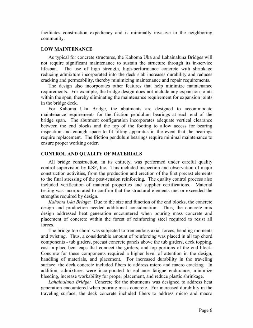
facilitates construction expediency and is minimally invasive to the neighboring community.
LOW MAINTENANCE As typical for concrete structures, the Kahoma Uka and Lahainaluna Bridges will
not require significant maintenance to sustain the structure through its in-service lifespan. The use of high strength, high-performance concrete with shrinkage reducing admixture incorporated into the deck slab increases durability and reduces cracking and permeability, thereby minimizing maintenance and repair requirements.
The design also incorporates other features that help minimize maintenance requirements. For example, the bridge design does not include any expansion joints within the span, thereby eliminating the maintenance requirement for expansion joints in the bridge deck.
For Kahoma Uka Bridge, the abutments are designed to accommodate maintenance requirements for the friction pendulum bearings at each end of the bridge span. The abutment configuration incorporates adequate vertical clearance between the end blocks and the top of the footing to allow access for bearing inspection and enough space to fit lifting apparatus in the event that the bearings require replacement. The friction pendulum bearings require minimal maintenance to ensure proper working order.
CONTROL AND QUALITY OF MATERIALS All bridge construction, in its entirety, was performed under careful quality
control supervision by KSF, Inc. This included inspection and observation of major construction activities, from the production and erection of the first precast elements to the final stressing of the post-tension reinforcing. The quality control process also included verification of material properties and supplier certifications. Material testing was incorporated to confirm that the structural elements met or exceeded the strengths required by design.
Kahoma Uka Bridge: Due to the size and function of the end blocks, the concrete design and production needed additional consideration. Thus, the concrete mix design addressed heat generation encountered when pouring mass concrete and placement of concrete within the forest of reinforcing steel required to resist all forces.
The bridge top chord was subjected to tremendous axial forces, bending moments and twisting. Thus, a considerable amount of reinforcing was placed in all top chord components - tub girders, precast concrete panels above the tub girders, deck topping, cast-in-place bent caps that connect the girders, and top portions of the end block. Concrete for these components required a higher level of attention in the design, handling of materials, and placement. For increased durability in the traveling surface, the deck concrete included fibers to address micro and macro cracking. In addition, admixtures were incorporated to enhance fatigue endurance, minimize bleeding, increase workability for proper placement, and reduce plastic shrinkage.
Lahainaluna Bridge: Concrete for the abutments was designed to address heat generation encountered when pouring mass concrete. For increased durability in the traveling surface, the deck concrete included fibers to address micro and macro
Page 6
cracking. In addition, admixtures were incorporated to enhance fatigue endurance, minimize bleeding, increase workability for proper placement, and reduce plastic shrinkage. The temperature in the superstructure was also monitored such that the connection of superstructure to abutments could be made at the optimum point.
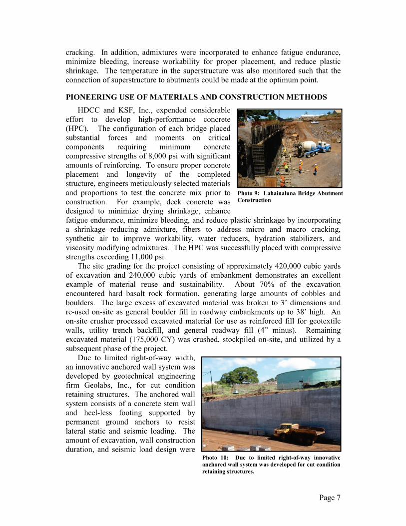
PIONEERING USE OF MATERIALS AND CONSTRUCTION METHODS HDCC and KSF, Inc., expended considerable
effort to develop high-performance concrete (HPC). The configuration of each bridge placed substantial forces and moments on critical components requiring minimum concrete compressive strengths of 8,000 psi with significant amounts of reinforcing. To ensure proper concrete placement and longevity of the completed structure, engineers meticulously selected materials and proportions to test the concrete mix prior to construction. For example, deck concrete was designed to minimize drying shrinkage, enhance fatigue endurance, minimize bleeding, and reduce plastic shrinkage by incorporating a shrinkage reducing admixture, fibers to address micro and macro cracking, synthetic air to improve workability, water reducers, hydration stabilizers, and viscosity modifying admixtures. The HPC was successfully placed with compressive strengths exceeding 11,000 psi.
The site grading for the project consisting of approximately 420,000 cubic yards of excavation and 240,000 cubic yards of embankment demonstrates an excellent example of material reuse and sustainability. About 70% of the excavation encountered hard basalt rock formation, generating large amounts of cobbles and boulders. The large excess of excavated material was broken to 3’ dimensions and re-used on-site as general boulder fill in roadway embankments up to 38’ high. An on-site crusher processed excavated material for use as reinforced fill for geotextile walls, utility trench backfill, and general roadway fill (4” minus). Remaining excavated material (175,000 CY) was crushed, stockpiled on-site, and utilized by a subsequent phase of the project.
Due to limited right-of-way width, an innovative anchored wall system was developed by geotechnical engineering firm Geolabs, Inc., for cut condition retaining structures. The anchored wall system consists of a concrete stem wall and heel-less footing supported by permanent ground anchors to resist lateral static and seismic loading. The amount of excavation, wall construction duration, and seismic load design were
Photo 9: Lahainaluna Bridge Abutment Construction
Photo 10: Due to limited right-of-way innovative anchored wall system was developed for cut condition retaining structures.
Page 7
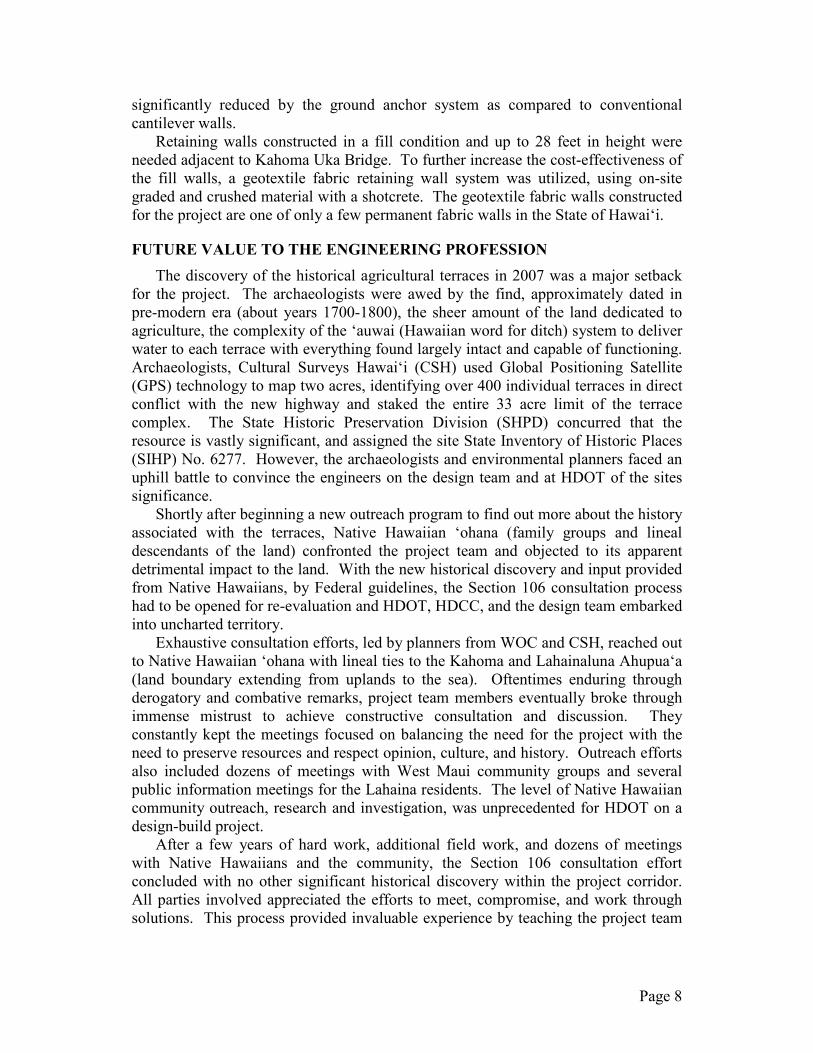
significantly reduced by the ground anchor system as compared to conventional cantilever walls.
Retaining walls constructed in a fill condition and up to 28 feet in height were needed adjacent to Kahoma Uka Bridge. To further increase the cost-effectiveness of the fill walls, a geotextile fabric retaining wall system was utilized, using on-site graded and crushed material with a shotcrete. The geotextile fabric walls constructed for the project are one of only a few permanent fabric walls in the State of Hawaiʻi.
FUTURE VALUE TO THE ENGINEERING PROFESSION The discovery of the historical agricultural terraces in 2007 was a major setback
for the project. The archaeologists were awed by the find, approximately dated in pre-modern era (about years 1700-1800), the sheer amount of the land dedicated to agriculture, the complexity of the ‘auwai (Hawaiian word for ditch) system to deliver water to each terrace with everything found largely intact and capable of functioning. Archaeologists, Cultural Surveys Hawai‘i (CSH) used Global Positioning Satellite (GPS) technology to map two acres, identifying over 400 individual terraces in direct conflict with the new highway and staked the entire 33 acre limit of the terrace complex. The State Historic Preservation Division (SHPD) concurred that the resource is vastly significant, and assigned the site State Inventory of Historic Places (SIHP) No. 6277. However, the archaeologists and environmental planners faced an uphill battle to convince the engineers on the design team and at HDOT of the sites significance.
Shortly after beginning a new outreach program to find out more about the history associated with the terraces, Native Hawaiian ‘ohana (family groups and lineal descendants of the land) confronted the project team and objected to its apparent detrimental impact to the land. With the new historical discovery and input provided from Native Hawaiians, by Federal guidelines, the Section 106 consultation process had to be opened for re-evaluation and HDOT, HDCC, and the design team embarked into uncharted territory.
Exhaustive consultation efforts, led by planners from WOC and CSH, reached out to Native Hawaiian ‘ohana with lineal ties to the Kahoma and Lahainaluna Ahupua‘a (land boundary extending from uplands to the sea). Oftentimes enduring through derogatory and combative remarks, project team members eventually broke through immense mistrust to achieve constructive consultation and discussion. They constantly kept the meetings focused on balancing the need for the project with the need to preserve resources and respect opinion, culture, and history. Outreach efforts also included dozens of meetings with West Maui community groups and several public information meetings for the Lahaina residents. The level of Native Hawaiian community outreach, research and investigation, was unprecedented for HDOT on a design-build project.
After a few years of hard work, additional field work, and dozens of meetings with Native Hawaiians and the community, the Section 106 consultation effort concluded with no other significant historical discovery within the project corridor. All parties involved appreciated the efforts to meet, compromise, and work through solutions. This process provided invaluable experience by teaching the project team
Page 8
to be sensitive to a community’s history and culture and to be patient when working through issues with the community to establish solutions.
CONCLUSION The discovery of the historical agricultural terraces was a major setback for the
project. The roadway was realigned to avoid the culturally significant site. Kahoma Uka Bridge, which was previously designed to be straight, now required a horizontal curve which magnified the complexity of this structure. The redesign of the highway caused a delay in the construction and anticipated completion of the project. WOC and their sub-consultants were faced with many challenges and overcame them by having experienced team members and working with the community.
Expediency in design and construction helped condense the overall project timeline and reduced impacts to those affected by the project. To help expedite construction of Kahoma Uka and Lahainaluna Bridges, the superstructures were developed utilizing a combination of precast, post-tensioned, and cast-in-place construction, thereby taking advantage of their production and installation efficiencies. Using on-site cast members in lieu of precast bridge girders eliminated the traffic congestion, delays and hazards that may have resulted from the transportation of these elements to the construction site. Taking advantage of these efficiencies helped to condense the project schedule and minimize the overall construction timeline.
The project immediately and significantly improved traffic for the West Maui community by dispersing traffic volume away from a known choke point along the existing highway. Traffic associated with morning and afternoon school hours is distributed between two intersections instead of one, alleviating backup along the highway.
This project represents a collaborative and successful partnership between HDOT and the project team utilizing the design-build delivery system.
ACKNOWLEDGEMENTS The authors appreciate the support of ACECC.
Page 9