horita utg-50horita.com/downloads/manuals/horita utg-50 manual.pdf · the utg-50 incorporates an...
TRANSCRIPT

HORITA UTG-50
GPS Based, Multi-Frame Rate
Universal SMPTE Time Code Generator
USER MANUAL
For Models UTG-50, RM-50/UTG, SR-50/UTG
Software Version UTG201
Doc. 073164-00
Rev. C
(C) Copyright 2014
P.O. Box 3993, Mission Viejo, CA 92690 (949) 489-0240

2
COPYRIGHT
(C) 2014 HORITA Co., Inc., All rights reserved
No part of this document may be copied or reproduced in any form or by any means without prior written consent of
HORITA Co., Inc., P.O. Box 3993, Mission Viejo, CA 92690
HORITA Co. makes no warranties with respect to this documentation and disclaims any warranties of merchantability or
fitness for a particular purpose. HORITA, its logo, and UTG-50 are trademarks of HORITA Co., Inc.

3
Table Of Contents
1 GENERAL 7
1.1 Word and Acronym Definitions 7
1.2 SMPTE Time Code 8
SMPTE Time Code Format 9
SMPTE Time Code Bits 9
Time Bits 9
User Bits 9
Time Code Frame Rates 9
Time Code Time and Real Time 9
Time Code and Time of Day/Date 9
Drop Frame Time Code 10
Non-Drop Frame Time Code 10
2 FEATURES 11
3 CONNECTING 13
3.1 Connecting Power 13
3.2 Operating From Battery Power 13
3.3 Connecting The GPS Antenna 13
3.4 Locating The GPS Antenna 13
3.5 Connecting Video IN and OUT 14
Figure 3-1, Basic UTG-50 Hookup 14
3.6 Connecting Time Code IN and OUT 14
3.7 Connecting The 1PPS and Alarm Outputs 14
1PPS Signal 14
Alarm Signal 14
3.8 Selecting Signal For Output on RCA Connector 14
3.9 DB9 Output Signals 14
4 OPERATING 15
4.1 General 15
4.2 Front Panel Switches 15
4.3 POWER Switch and LED Operation 15
Table 4-1, UTG-50 LED Operation 15
4.4 POWER ON System Reset 15
4.5 MODE Switch 15
4.6 POSITION Switch 15
4.7 CHAR Switch 16
4.8 UTG-50 Mode Flow Diagram Description 16
Figure 4-1, UTG-50 Mode Flow Diagram 16
4.9 Entering and Exiting the Setup Menus 16
4.10 Selecting Different Setup Menu Items 16
4.11 Changing the Selected Menu Item 17
4.12 General UTG-50 Setup Operations 17
4.13 DISPLAY Setup 17
4.14 TCG/SYSTEM Setup 17
4.15 TC/TIME Setup 17
4.16 UB/DATE Setup 18
4.17 "UTG SETUP HELP" Screen 18
GPS/S GLOBL POS SYS 18
MAN/M MANUL ENT DAT 18
PRE/P PRESET 18
RTC/C REAL TIME CLK 18
TCR/R TIME CODE RDR 18
T&D TIME & DATE 19

4
Table Of Contents
ZN/Z ZONE 19
* 1PPS 19
DATA :USER =SYS 19
4.18 "DISPLAY SETUP" Menu 19
CHAR:WHT 19
BACK: ON 19
SIZE H:1X V:2X 19
SCR POS H:18 V:28 20
NUM LINES 1-9:N 20
CLR:N 20
UTG200 20
OPER 20
4.19 "TCG/SYSTEM SETUP" Menu 20
GPS=T&D 21
* 1PPS 21
TC ADV: .0S 21
RTC JAM TIME:OFF 21
DATE: OFF 21
TIME: 21
DATE: 21
TCG:25F 21
TC REF=GPS 21
JAM/LOK SETUP: AUTO 22
JAM:1X =Y 22
TOL: 00:02 22
LOK:GPS=Y 22
ERR 00:00 22
STD:NTSC 22
SYS RST:N 22
4.20 "TC/TIME SETUP" Menu 23
PRE: 00:00:00:00 23
TCR:24F 00:00:00:00 23
TCR FRAME RATE DISPLAY 23
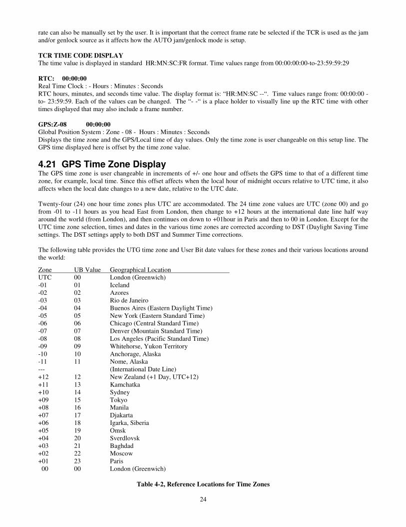
TCR TIME CODE DISPLAY 24
RTC: 00:00:00 24
GPS:Z-08 00:00:00 24
42.21 GPS Time Zone Display 24
Table 4-2, Reference Locations for Time Zones 24
GPS TIME DISPLAY 24
4.22 Daylight Savings Time 25
DST:ENA BEG>-Y-<END 25
MN/:DAY 04/02 10/12 25
DST:ENA 25
BEG>-Y-<END 25
MN/:DAY 04/02 10/12 25
MN/:SUN 04/2 10/1 25
TC REF:GPS BKUP:RTC 25
TC REF:GPS 25
4.23 Backup Operation and Alarm Signal 26
BKUP:RTC 26
OUT= 00:00:00:00 26

5
Table Of Contents
4.24 “UB/DATE SETUP" Menu 26
UB NUM 8 7 :6 5:4 3 :2 1 26
DATE:HOR ZN:YR:MN:DY 26
DATE:HOR 26
ZN:YR:MN:DY 27
MAN/M 0 0: 1 0: 0 8 : 1 2 27
TCR/R 0 0: 0 9: 2 2 : 1 3 27
RTC/C - - 0 8- 0 9- 1 0 27
GPS/S Z-0 8 0 9-1 0- 1 1 27
UB SRC: Z Z: RR:R R: RR 27
TIME ZONE SELECTION FOR UB-87 27
DATE SELECTION FOR UB-65-43-21 27
OUT= 0 0:0 0:0 0:0 0 27
4.25 Time Code Jam and Genlock Operations 27
4.26 "Jamming" 28
4.27 "Genlock" 28
4.28 "AUTO" Jam/Lok Setup Mode Operation 29
4.29 Genlock to an External Time Code Input 29
4.30 Genlock to GPS or RTC 29
4.31 Genlock to Video 29
Table 4-3, Jam and Genlock "AUTO SETUP" 29
Default Settings
4.32 Time Code Frame Rate Translation 30
4.33 Time Code Backup or Repair 30
4.34 Entering and Editing Source ID Data 30
4.35 Source ID Character Selection 30
4.36 Character Set 31
Table 4-4, Video Overlay Character Set 31
4.37 Inserting Spaces and Deleting Characters 31
4.38 Centering a Line of Text 32
4.39 Turning the Display Off and On 32
5 MAINTENANCE 5.1 Cleaning 33
5.2 Service and Troubleshooting 33
5.3 Adjustments 33
Figure 5-1, Adjustment Locations 33
5.4 Horizontal Size Adjustment 33
5.5 Video Level & Equalization Adjustment 33
6 SPECIFICATIONS Power 35
Video 35
Time Code 35
GPS Receiver 35
RTC 35
Alarm Signal 35
Switches 36
Environment 36
Dimensions 36
Weight 36

6
7. SOFTWARE REVISION NOTES UTG200 Initial release
UTG201 The UTG-50 had a minor software revision from UTG200 to UTG201 on 04-16- 2014. This
revision fixed a problem in recalling some time zone settings, and enhanced operation of the
DST setup for “Summer Time” operation.
The paragraphs affected and revised by the UTG201 are 4.18 (OPER/TEST), 4.21
and 4.22.

7
1 GENERAL
This manual provides instructions for installing and operating the HORITA UTG-50 Universal Time Code Generator
(UTG).
The UTG-50 is a “Master” SMPTE time code generator intended for use in field, studio, editing, engineering, and post
production situations.
The UTG-50 generates “Longitudinal” (also called “Linear”) format SMPTE time code (LTC) at various user selectable
frame rates. Both balanced and un-balanced output signals are provided. The UTG-50 can “jam” and “genlock” the
generated time code to various internal and external time and video reference signals as required.
The UTG-50 can set the time code time to the “time-of-day” and set the time code “user bits” to the date for use in
situations where it is desired that the time code represent the actual time of day and date. This is useful for driving analog,
digital, and video overlay studio time-of-day clock displays. In this application, the UTG-50 may be setup to perform
automatic Daylight Savings Time (DST) time and date correction if desired.
The UTG-50 consists of a highly accurate crystal controlled multi-frame-rate SMPTE longitudinal Time Code Generator
(TCG). The initial TCG start time value can be manually preset by the user or electronically preset (jammed) from an
external SMPTE time code input, from an internal GPS receiver, or from an internal Real Time Clock (RTC) chip.
After initial presetting and startup, the TCG can be set to thereafter “free run” or to genlock (also termed phase lock) to an
externally applied time code or video reference signal or to the internal GPS receiver or RTC chip.
As the TCG generates the time code, the original reference signal used to preset the TCG time is monitored and its time
value is compared to that of the UTG-50 time code. If there is a time error difference that exceeds a user preset value, the
TCG is then again preset (jammed) to the source time.
If the original preset signal fails to occur for longer than about five minutes, the UTG-50 will output an “Alarm” signal and
then either continue to “free run” or will switch over to a user’s pre-selected backup source for the time and date.
Besides its use as a genlock reference, the composite video input to the UTG-50 is also overlaid with various UTG-50
operational setup menus and time and date displays. Additionally, the user can enter and display up to 9 lines of 20
characters each of source ID or other alphanumeric titling information.
All of the UTG-50 setup information, operating mode selection, and titling information is saved in battery backed up, non-
volatile memory, and restored at power up.
1.1 Word and Acronym Definitions Word and acronym definitions used in this manual are explained below:
DF “Drop Frame” time code - See “SMPTE Time Code”
DST Daylight Savings Time - also called “summer time” in most European countries, is the practice of temporarily
advancing clocks during the summer so that afternoons have more daylight and mornings have less.
Typically clocks are adjusted forward one hour near the start of spring and then adjusted backward in
autumn.
EBU European Broadcast Union - A European standards setting organization.
FPS Frames-Per-Second - “Frame rate” of video, film, or time code. The number of times in a second that a frame of
video, film, or a time code is changed or updated.
Freerun Free running - Not locked to a reference. “free range” time code See Genlock
Genlock To lock signals together such that one is a timing reference for the other. For example, to lock time code
generation to a video reference so that each frame of time code is generated in exact synchronism with the
generation of each frame of video.

8
GPS Global Positioning System - A system of satellites that broadcasts precise time and other signals that allow GPS
receivers to accurately determine the time-of-day, date, and their geographical location on the Earth.
GMT Greenwich Mean Time - See UTC
Jam To electronically preset a time code generator to the same jammed time as another time source to cause the
generated time code to have the same time value as that of the source time.
LTC Longitudinal/Linear Time Code - See “SMPTE Time Code”.
NDF “Non-Drop Frame” time code - See “SMPTE Time Code”
NTSC National Television Systems Committee - US standards setting organization. Also referred to as the 525line,
29.97FPS video standard for the first US color television system.
PAL Phase Alternating Line - The 625 line, 25FPS video standard for one of the first European color television
systems.
RTC Real-Time-Clock - A clock that keeps the real time of day and (usually) date. In the UTG-50 the RTC is a
computer chip.
SMPTE Society of Motion Picture and Television Engineers - A US standards setting organization. Usually Pronounced
“sim-tea” or “simpt-tea”
TC Time Code - See “ SMPTE Time Code”
TCR Time Code Reader – reads (decodes) SMPTE time code. The UTG-50 incorporates an internal multi-frame-rate
SMPTE time code reader., sometimes referred to in this manual as the “UTG-50 TCR” or just the “TCR”.
TCG Time Code Generator - generates SMPTE time code. The UTG-50 incorporates a multi-frame-rate internal
SMPTE time code generator, sometimes referred to in this manual as the “UTG-50 TCG” or just the “TCG”.
TZ Time Zone - a geographical area on the earth that has been defined to have particular positive or negative time
offset from UTC, usually of a whole integer hours value. UTC time is adjusted by the time zone value to
produce “local” time (and date).
UB User Bits - See “SMPTE Time Code”
UTC Coordinated Universal Time (abbreviated UTC) is the primary time standard by which the world regulates clocks
and time. Computer servers, online services and other entities that rely on having a universally accepted time use
UTC for that purpose.
UTC time is based on International Atomic Time (TAI) with leap seconds added at irregular intervals to
synchronize the time with the earth’s rotation
The UTC time zone is zero “00”, popularly known as GMT (Greenwich Mean Time), or Zulu time. Local time
differs from UTC by the number of hours of your time zone. Time zones around the world can be expressed as
positive or negative offsets from UTC.
GPS time is the atomic time scale implemented by the atomic clocks in the GPS ground control stations and the
GPS satellites themselves. GPS time was zero at 0h 6-Jan-1980 and, since it is not adjusted by leap seconds,
GPS is currently (2013) ahead of UTC by 15 seconds. The GPS receiver in the UTG-50 corrects GPS time and
date to that of UTC time and date.
1.2 SMPTE Time Code
SMPTE time code is an electronic timing signal that assigns a unique number to identify each individual frame (image) of
video or film. SMPTE time code was initially developed in the 1960’s to facilitate the operation of electronic video tape
editing systems, but has since found numerous other applications.

9
As an electronic signal, SMPTE time code has a frequency range that allows it to be recorded on an audio recorder or the
audio track of a video recorder.
Sometimes SMPTE time code is referred to as “longitudinal” or “linear” time code because of it being recorded on a
continuous path along the length of a video or audio tape, rather than being recorded on slanted "tracks" via a spinning head
as is the method for video recording.
SMPTE Time Code Format - Instead of numbering video or film frames starting with frame number 1 and then counting
on up from there, SMPTE time code numbers each frame in an hours, minutes, seconds, and frame number format:
“HR:MN:SC:FR”. This produces a “digital clock” type of time representation for each frame number.
SMPTE Time Code Bits - The SMPTE time code format provides eighty (80) digital bits of information per frame.
Sixteen (16) of these bits are used to assist in locating and properly decoding the other 64 bits of the time code.
Time Bits - Thirty two (32) of the remaining 64 bits are used to encode the hours, minutes, seconds, and frame number of
the actual SMPTE time code time value for a particular video/film frame.
User Bits - The last remaining thirty-two (32) bits are “extra” and are available to encode "user" information as desired. In
the UTG, the user bits are used to encode the date and time zone.
Time Code Frame Rates - SMPTE time code can be generated at different frame rates in order to accommodate the
variety of video and film frame rates in use today. This match of time code and image frame rates is necessary in order to
be able to assign a specific time code number to each individual image frame. Matched frame rates insure that a time code
frame number does not “straddle” more than one frame, or more than one frame does not straddle more than one time code
number.
Some of the more common frame rates are as follows:
23.976FPS - This frame rate is slightly slower than the standard 24FPS film frame rate by an amount proportional to that of
the difference between the 29.97FPS and 30FPS video frame rates. Used in video-to-film transfer applications.
24FPS - standard film frame rate.
25FPS - European PAL television frame rate.
29.97FPS - US NTSC color television frame rate.
29.97DF - Drop frame time code frame rate - Drop frame time code is synchronized to the US NTSC television frame rate
of 29.97FPS and maintains a nominal “real time” time value.
29.97NDF - Non-drop frame time code frame rate - Non-drop frame time code is synchronized to the US NTSC television
frame rate but its actual time value runs slower than that of real time.
30FPS - US black and white television frame rate.
Time Code Time and Real Time - “Real time” is the passage of time as measured by a clock. Although SMPTE time
code has a clock type time format, its time value may or may not match that of real time. This means that even though it
may look like the “seconds” of the time code are changing once a second, they may be changing at a slower or faster rate.
The time value of SMPTE time code running at 24FPS, 25FPS, and 30FPS matches that of real time. The time value of
time code running at 29.97FPS DF SMPTE time code pretty much matches that of real time
The time value of 23.976FPS and 29.97FPS NDF SMPTE time code runs slower and does not match that of real time.
Time Code and Time of Day/Date - Although it ultimately depends on the accuracy of the time code generator, when
running at one of the integer frame rates or 24, 25, or 30FPS, SMPTE time code can be set to and will maintain accurate
time-of-day time.
10
In addition, because the SMPTE time code format has provision for including extra information, the date can be included
along with the time of day. The date can be in year/month/day, Julian, or other formats, and may include time zone
information as well.
When referenced to the time of day and date, SMPTE time code can be used to operate various analog and digital real-time
time/date clock displays, including LED, LCD, video overlay, and those with hours, minutes and seconds hands.
Another use for time of day/date SMPTE time code is as the time and date reference for controlling various types of
automated television playback and recording equipment.
Drop Frame Time Code - The exception to time code time matching real time is the time code used with the NTSC video
system. In this system the frame rate as represented by the frame numbers is 30FPS. However, the frame numbers are
counted up by a time base that is running just slightly slower than 30FPS, running at only 29.97FPS. So, after counting 30
frames, it hasn’t actually been one second of real time. It’s been a little less.
As time goes by, the amount of real time error continuously increases until it eventually lags that of real time by about 3 1/2
seconds an hour. To compensate for this error, the normal frame number counting sequence is altered slightly during
generation of the time code.
In 30FPS time code the frame number count starts at frame “00”, advances on up to frame number “29”, then wraps around
to frame 00 and starts over. Each time the frame count wraps around to frame 00 the seconds change to the next second,
then eventually the minutes and hours change in typical clock fashion. However, after counting for one minute the time
code time value has fallen behind real time by about two frames worth of time, about 66 thousands of a second (66ms).
The method chosen to correct this two frames a minute lag in real time was simply to start the frame count at 02 instead of
00 at the start of each new minute. Then continue counting as normal. This is called “drop-frame” time code, although no
frames of anything are actually dropped.
So, with drop frame time code, at the start of each minute the frame count wraps from 29-to-02 instead of 29-to-00,
skipping the numbers 00 and 01. The result is that the SMPTE time code time gradually falls behind real time for a minutes
worth of time, then jumps ahead when the next new minute starts, then gradually falls behind again. Although there is a
continuously varying short time error, the overall real time error is greatly reduced.
Actually, to fine tune the real time accuracy of drop frame time code, the once a minute drop-frame correction is not
performed whenever the minutes change occurs at the start of a new tens of minutes. At the start of each tens-of-minutes
the frame number count wraps normally, from 29-to-00, rather than from 29-to-02.
Drop frame correction of the time code is a continuous process and it is not noticeable that it is occurring when looking at a
real time clock display using 29.97DF SMPTE time code.
Non-Drop Frame Time Code - Non-drop frame time code is time code using the 30FPS time code numbering system that
is actually counted or advanced at the slightly slower frequency of 29.97 times-per-second, and in which drop frame
correction is not performed. This causes the time code real time value to lag behind and not match that of actual real time.
However, in this format there are no skipped frame numbers.

11
2 FEATURES
• Five separate setup screens titled HELP, DISPLAY, TCG/SYSTEM, TC/TIME, and UB/DATE, plus “Auto” setup
modes provide simple and easy means to select time code frame rates, jam and genlock reference time sources, set time and
date values, GPS, RTC, and DST operation, plus adjust source ID video overlay display character attributes such as size,
position, black/white, etc..
• The UTG-50 is multi-frame-rate and can generate time code at 23.976FPS, 24FPS, 25FPS, 29.97FPS DF (Drop
Frame), 29.97FPS NDF (Non-Drop Frame), and 30FPS (non-drop frame), with a freerun accuracy of +/- 1 frame-per-
hour.
• The UTG-50 can manually or automatically "jam" (preset) to an externally applied SMPTE time code time and date, to
the GPS time and date, or an internal RTC time and date.
• An automatic jam of the UTG-50 can be set to take place if the time difference between the UTG-50 time code
generator and the selected UTG-50 time source exceeds a user settable value of from zero seconds and frames to over
59 seconds and 29 frames.
• The UTG-50 can be set to "freerun" or to "genlock" (phase lock) the generated time code to either the incoming video,
the TCR time code input, the GPS signal, or the RTC.
• A special UTG-50 “Auto Jam/Genlock” setup mode automatically sets up the UTG-50 jam type, jam error tolerance,
and genlock mode for optimum operation according to the UTG-50 frame rate and jam source selection.
• The UTG-50 "user bit" portion of the generated time code can be set to match that of the jam source or can be
manually preset.
• The Daylight Savings Time (DST) date can be entered as a specific beginning/ending month and day or
beginning/ending month and Sunday.
• UTC time from the GPS system can be offset to that of a local time zone. This time zone offset also automatically
adjusts the date as necessary .
• The UTG-50 TCR reads SMPTE/EBU time code at frame rates of 23.976FPS, 24FPS, 25FPS, drop and non-drop
frame 29.97FPS, and 30FPS, at play speed +/- approximately 15%.
• The UTG-50 TCR "auto FPS" detect mode automatically detects 23.976, 25, 29.97DF, and 29.97NDF frame rates.
Other frame rates of 24/30FPS can be manually set.
• The RTC time and date can be manually set or automatically jammed each second to either the GPS or the TCR time
and date.
• The UTG-50 can display the generated time code and user bit values as a video overlay keyed into the NTSC or PAL
composite video input signal.
• The UTG-50 video overlay display can be set as black or white characters, with or without a background, with size
selectable between four horizontal and four vertical values.
• The nine lines of the video overlay display can be automatically numbered (and unnumbered) from 1-9 for easier
placement of time code or source ID information on the screen.
• Front panel LED “blinks” to indicate 1-PPS, time code is being read and video is present.
• Balanced and unbalanced SMPTE Time Code, and 1-PPS and Alarm signals are output.
• Operates from a small AC power adapter, which is included, or can be operated in the field from 9-to-12 volts DC
battery power.

12
• Available in desktop (UTG-50), Rackmount (RM-50/UTG), Rackmount Add On (AO-50/UTG) or Shortrack (SR-
50/UTG) models.

13
3 CONNECTING
3.1 Connecting Power Included with your UTG-50 is an AC power adapter that provides a 9 volt, 500 milliamperes DC output. This adapter is
equipped with a DC power connector that has a 2.5mm inner diameter and a 5.5mm outer diameter. The center pin
receptacle is "+" (positive) voltage polarity.
Insert the power plug into the UTG-50 "+9V POWER" connector and plug the adapter into 110-120 volt, 60-Hz AC power.
Note that you may also have been supplied with an equivalent power adapter suited for use with other mains supply
voltages and for operation at 50-Hz AC power.
WARNING:
ELECTRICALLY OPERATED PRODUCT
As with all electrical products, precautions should be observed during handling and use to prevent electrical shock.
NOTE:
Make sure the plug is inserted all the way into the power connector. The UTG-50 has internal protection circuitry to prevent
it from being damaged should the wrong polarity of power be applied. However, do not use an adapter of more than 9 volts
at 500 milliamperes or damage to the UTG-50 may result.
3.2 Operating From Battery Power You can operate your UTG-50 from battery power in order to use it in the field.. The UTG-50 operates from 9-to-12 volts
DC.
3.3 Connecting The GPS Antenna The UTG GPS receiver antenna has a five (5) meter cable with a “screw-on” type SMA coaxial RF connector. Simply
screw the SMA connector at the end of the antenna cable onto the SMA connector jack on the UTG. Unscrew the connector
to disconnect the antenna cable.
3.4 Locating The GPS Antenna Although, like other GPS systems, the UTG-50 GPS system does tend to work indoors, for best operation the GPS antenna
should be located where the GPS satellites signals will not be blocked by foliage, buildings, or other structures. Generally
this means placing the antenna where there is an unobstructed view of a large area of the sky. A rooftop, skylight, or un-
tinted window location is likely to be suitable.
It should also be noted that the antenna should be kept away from exposure to high levels of RF energy which can cause
receiver overload and failure of the GPS receiver to detect the extremely weak GPS signals. This means avoiding locations
near transmitter antennas unless the antenna can be shielded from the transmitter and still have a clear view of the sky.
3.5 Connecting Video IN and OUT Figure 3-1 shows a basic hookup for the UTG-50 when used with a typical video source and a video monitor.
Video Figure 3-1, Basic UTG-50 Hookup
Connect video from the video source to the BNC connector labeled VIDEO IN on the UTG-50. Connect VIDEO OUT from
Video In Video Out
Time Code In Time Code Out
GPS Antenna 1PPS/Alarm

14
the UTG-50 to a video monitor.
When the UTG-50 is powered up, the VIDEO IN input is terminated at 75 ohms. When powered off, video is looped
directly from VIDEO IN to VIDEO OUT, bypassing the UTG-50.
3.6 Connecting Time Code IN and OUT Time Code In
Connect line level time code from the time code source to the RCA connector labeled TC IN on the UTG-50.
Time Code Out The UTG-50 provides both balanced and unbalanced time code outputs. The un-balanced output is provided on an RCA
connector The balanced time code output is available on both an XLR and DB9 connectors on Rackmount and Shortrack
UTG-50 packages while, because of the smaller rear panel, the desktop UTG-50 provides the balanced time code output
only on the DB9 connector.
Connect to either the balanced or un-balanced time code signals as desired.
Pinouts for the DB9 connector are described in later paragraphs.
3.7 Connecting The 1PPS and Alarm Outputs The UTG-50 provides both 1PPS and Alarm output signals. The DB9 connector has both outputs available, while a separate
RCA output is available for selection of either one or the other.
1PPS Signal The 1PPS signal from the UTG-50 is a negative going pulse of approximately 5ms width and goes from +5V to 0V. The
leading edge is within a few microseconds of the UTG tick. The 1PPS signal is output on Pin-3 of the DB9 connector.
Alarm Signal The Alarm signal is an “open collector” pulldown to ground type of signal and the alarm condition is when the signal goes
high. The pulldown can sink 100ma. The alarm signal is output on Pin-4 of the DB9 connector
3.8 Selecting the Signal for Output on RCA Connector Either the 1PPS or the Alarm signal can be output on the RCA connector. Refer to Section-5 for instructions on how to gain
access to the inside components of the UTG-50. On the small circuit board is a jumper selector labeled JP1. Place the
removable jumper between ALARM/RCA to select the Alarm signal or between 1PPS/RCA to select the 1PPS signal.
3.9 DB9 Output Signals The DB9 connector pinouts and associated signals are as follows, and are also labeled on the UTG-50 rear panel:
Pin Signal
1 TC+
2 TC-
3 1PPS
4 Alarm
5 N/C Reserved
6 N/C Reserved
7 Gnd
8 Gnd
9 Gnd

15
4 OPERATING
4.1 General The following paragraphs describe the general scheme for setting up and operating the Horita UTG-50. Because of the
variety in both the needs of the user and the capabilities of the UTG-50, this manual provides only descriptions of the
functions of the various UTG-50 settings, along with a more general description of UTG-50 operation. Specific setup of all
of the UTG-50 parameters for a particular need or application is left to be determined by the user, after acquiring an
understanding of the capabilities and each of the specific functions of the UTG-50.
This section of the manual starts with a description of powering up the UTG-50 and operating its switches to enter SETUP
mode and navigate through and make selections from the various setup menus.
This is followed by a general description of how to go about using each of the setup menus to set up the UTG-50 for typical
operation as a "master" SMPTE time code generator, and then a detailed description of each setup menu and menu item
selection and a more detailed description of “Jamming” and “Genlocking” operation and frame rate conversion.
Finally, instructions describe how to enter and edit video overlay source ID information.
Note that the terms UTG and UTG-50 are used interchangeably in this manual and that the UTG-50 internal SMPTE TCR
and TCG are sometimes referred to as the UTG-50 TCR or UTG-50 TCG, or sometimes simply as the TCR or TCG.
4.2 Front Panel Switches There are four toggle switches on the front panel, labeled POWER, MODE, POSITION, and CHAR. Operation of each of
these switches is described in the following paragraphs.
To operate the UTG-50 after connecting it into your system as described in SECTION 3 of this manual, first connect video
and time code in and out, locate the GPS antenna as required, connect power from the power adapter and set the UTG-50
POWER switch to ON.
4.3 POWER Switch and LED Operation The power switch turns UTG-50 power ON and OFF. A red LED located above the power switch lights to indicate power is
on and also blinks at different rates to indicate presence of the time code and video inputs as described below in Table 4-1.
LED Condition Meaning OFF Power OFF
1PPS blink Normal -TCG operating using user selected primary time source.
2PPS blink Error - TCG operating using user selected backup time source.
Table 4-1, UTG-50 LED Operation
4.4 POWER ON System Reset System reset initializes all variable data in the UTG-50 to default values. A hardware selected SYSTEM RESET function is
accessible by powering up the UTG-50 while holding the MODE switch in the "SETUP" position, then releasing it.
4.5 MODE Switch The MODE switch is a three position momentary action switch used to select and control the basic operate/setup modes of
the UTG. The center position of the switch is off and the switch can be actuated to either DISPLAY or SETUP positions.
This is described in greater detail in later paragraphs.
4.6 POSITION Switch The POSITION switch is a three position momentary action switch labeled with left/right and up/down arrows. This switch
is used to select various menu items when the UTG-50 is in SETUP mode, or to select the screen position for a character
when entering data in DISPLAY mode.

16
4.7 CHAR Switch The CHAR (character) switch is a three position momentary action switch labeled PREV/NEXT and is used to change a
selected menu item's value when in SETUP mode, for example Y/N, ON/OFF, etc., or to select a specific character when
entering data in DISPLAY mode.
4.8 UTG-50 Mode Flow Diagram Description
Figure 4-1 shows how operation of the UTG-50 changes as the MODE switch is actuated between DISPLAY and SETUP.
The down arrow means that the MODE switch is actuated down to SETUP, the up arrow means that the switch is actuated
up to DISPLAY.
1 Insert/Delete Spaces
2 Edit Video Overlay Text
UP arrow = DISPLAY
3 Video Overlay Display OFF
DOWN arrow = SETUP
4 Video Overlay Display ON
5 SETUP Menu Display ON
(Automatic, not from switch)
6 Next SETUP Menu
Figure 4-1, UTG-50 Mode Flow Diagram
The diagram shows that, for example, if the UTG-50 is displaying video overlay information (4), actuating the MODE
switch down to SETUP causes the UTG-50 to display a SETUP menu (5), while actuating the switch up to DISPLAY
causes the video overlay display to turn off (3).
When the UTG-50 first switches into SETUP mode (5), the setup menu and menu item previously selected are recalled and
displayed. Thereafter, each time the MODE switch is actuated to SETUP, the UTG-50 displays the next sequential setup
menu and the previously selected menu item (6-5).
When DISPLAY is selected from SETUP mode (5), the UTG-50 recalls and displays the previous video overlay display of
any source ID text and time and date information.
4.9 Entering and Exiting the Setup Menus There are five setup menus: UTG HELP SETUP, DISPLAY SETUP, TCG/SYSTEM SETUP, TC/TIME SETUP, and
UB/DATE SETUP. The setup menus allow selection of various display and character attributes, selection of operating
modes and functions, and entering of source ID information.
To display the setup menus, toggle the MODE switch to SETUP and release. Depending on the actual UTG-50 operating
mode, for example if entering source ID information, you may have to toggle the switch a few times to enter a setup menu.
The selected item on the setup menu is indicated by it "flashing" on and off, and the POSITION and CHAR switches now
serve to select and change the flashing menu item.
To exit the setup mode, actuate the MODE switch to DISPLAY and release.
4.10 Selecting Different Setup Menu Items Menu items are selected via the POSITION switch. Flashing of the menu selection moves on to the next item each time the
POSITION switch is actuated and released. Actuating the switch down causes the selection to move to the right and down,

17
actuating the switch up causes the reverse action. Holding the POSITION switch actuated causes quick scanning through
the menu items.
Generally, user selectable and changeable items are preceded by a colon “:” character. Menu items or values that result
from internal UTG-50 operation are not directly user selectable and are preceded by an equal “=” character.
4.11 Changing the Selected Menu Item After a menu item is selected, the choices available for that item are accessed via the CHAR switch. The choices may be
indicated by changes in names, like ON/OFF, WHT/BLK, or Y/N for yes or no. Actuating the CHAR switch down or up
scans forward or backward through the choices available. Holding the switch actuated causes automatic scanning through
the choices.
4.12 General UTG-50 Setup Operations
When first powered up, UTG-50 operation returns to whatever operational mode was selected when the UTG-50 was last
powered off. If it was powered off displaying a particular setup menu, that menu will be recalled and displayed. If
displaying time, date, and source ID, that information will be recalled and displayed.
If this is the very first time that the UTG-50 is powered up and operated, select the TCG/SYSTEM SETUP menu and
perform a system reset by selecting “Y” for the “SYS RST:N” menu item. Otherwise, select the DISPLAY SETUP menu
after power up and proceed with the general setup instructions provided for each setup menu. Following these general setup
instructions are detailed descriptions of each menu item selection available on each of the five UTG setup screens.
4.13 DISPLAY Setup From this menu choose if you want to display the time and/or date and on which of the 9 display lines they will be
displayed. For the time and date as well as for any source ID text entered, select the character color, black/white,
with/without a background surround, as well as the H & V size and position.
If you are going to enter source ID information when you leave the setup mode, you may want to automatically number the
9 text lines for reference to help position the text. You can turn the text off after entering the desired text. Later paragraphs
provide a detailed description of how to enter and edit text for source ID and other needs.
4.14 TCG/SYSTEM Setup Next, select the TCG/SYSTEM SETUP menu and choose if you want the RTC jammed to the GPS or TCR time and/or
date. A common choice would be to use the GPS for primary time and date and use the RTC as backup in case there is a
problem with GPS satellite reception. The RTC jam mode would be set to GPS so that the two times would always match.
Select the desired TCG frame rate, and set the jam and genlock operating mode. If there are no specific or special
requirements for jamming and genlocking the UTG-50, then simply set the JAM/LOK SETUP to AUTO. Set the video
standard (STD) to NTSC if operating in the US or to PAL if operating in the UK or Europe.
On the TCG/SYSTEM SETUP menu you can also check and verify that you are getting both the GPS message and 1PPS
signal from the GPS system.
4.15 TC/TIME Setup Next, proceed to the TC/TIME SETUP menu. On this menu all of the time sources that can jam and genlock the UTG-50
are displayed together on the same screen. These time sources are: PRESET, TCR, GPS, and RTC, and are selected via the
“TC REF” menu item.
In addition to the source times, the actual UTG-50 TCG time code output value is displayed at the bottom of the screen and
can be visually compared to the source times to verify desired jamming of the UTG-50.
Along with the reference time source selection is selection of a backup (BKUP) time source. The available selections are
the RTC, GPS, TCR, or OFF. The UTG-50 will switch over to this time reference after about 5 minutes of monitoring and
detecting that the selected time source has failed. If OFF is selected, the TCG will “free run” if the time source fails, then
seemlessly re-jam and/or genlock when the source is restored.
Also on this menu is where the GPS time zone is selected if GPS time and date are being used for the time reference. Set
the time zone to produce the “local” time and date from the UTG-50 time code output, or to any other desired time zone.
The UTG automatically adjusts both the time and the date for that time zone.

18
Select the DST date format and the date values for when DST correction is to begin and end. The methods avail are the
traditional “month and Sunday” or the “month and day”. Month and Sunday automatically repeats on the correct day every
year. Month and Day requires new date values be entered each year.
4.16 UB/DATE Setup Next, select the UB/DATE SETUP menu. On this menu all of the date sources that can be encoded into the UTG-50 time
code user bits for the date are displayed together on the same screen. These date sources are: MAN/M, TCR/R, RTC/C, and
GPS/S, and are selected via the UB SRC menu selection. This selection applies to UBs 65-43-21 which are used to encode
the Year, Month, and Day, into the SMPTE time code.
In addition to the source times, the actual TCG user bit output value is displayed at the bottom of the screen and can be
visually compared to the source dates to verify desired operation of the UTG-50.
Also on this setup menu is selection of the source for the time zone data output from the UTG-50, which is encoded into
user bits 87 of the time code. The available selections for the time zone source are from the GPS Time Zone (ZZ) setting,
TCR (RR) user bits 87, or manually entered data via the MAN (MM) 87 values..
Finally, select the encoding format for the user bit date data. This can be either the Horita (HOR) format or the Leitch (LEI)
format. The Horita format produces a human readable date display on common SMPTE time code readers that display user
bits. The Horita format is also used to adjust time and date displays on various Horita products. The Leitch data format
does not provide human readable date displays of user bit data, but is required if using Leitch time and date display
products.
4.17 "UTG SETUP HELP" Screen The UTG SETUP HELP screen provides a short description of the meaning of some of the abbreviations used on the UTG-
50 setup menus, as a quick refresher reference. There are no menu items for user selection on the HELP screen. The HELP
screen display is as follows:
*UTG SETUP HELP*
GPS/S GLOBL POS SYS
MAN/M MANUL ENT DAT
PRE/P PRESET DATA
RTC/C REAL TIME CLK
TCR/R TIME CODE RDR
T&D TIME & DATE
ZN/Z ZONE * 1PPS
DATA :USER =SYS
The following is a detailed explanation of each of the UTG SETUP HELP screen items.
GPS/S GLOBL POS SYS Both “GPS” and “S” are used on UTG-50 setup menus to indicate that the Global Position System can be
selected to provide or is providing the time and date to operate the UTG-50.
MAN/M MANUL ENT DAT
Both “MAN” and “M” are used on UTG-50 setup menus to indicate that user supplied manually entered data can
be selected to provide or is providing the time, date, and/or time zone information to operate the UTG-50.
PRE/P PRESET
“PRESET” and “P” are used on UTG-50 setup menus to indicate that user supplied manually entered data can be
selected to provide or is providing a time value to preset the TCG. The PRESET value is the starting time code
number for the TCG when it’s manually operated in the RUN/STOP mode.
RTC/C REAL TIME CLK
Both “RTC” and “C” are used on UTG-50 setup menus to indicate that the Real Time Clock can be selected to
provide or is providing the time and date to operate the UTG-50.
TCR/R TIME CODE RDR
Both “TCR” and “R” are used on UTG-50 setup menus to indicate that the SMPTE time code input to the UTG-50
can be selected to provide or is providing the time and date to operate the UTG-50.

19
T&D TIME & DATE
Time and date information from the GPS system is being received
ZN/Z ZONE
Both “ZN” and “Z” are used on UTG-50 setup menus to indicate that the user supplied manually entered time zone
value can be selected to provide or is providing an offset to the GPS UTC time and date so that the UTG-50
SMPTE time code output value is that for a different time zone, such as for “local” time and date.
* 1PPS
An asterisk (*) character flashes next to the "T&D" display each time the highly accurate 1PPS signal is received
from the GPS system. The 1PPS signal is separate from the actual time and date information also received from
the GPS system. The asterisk flashes on the help screen as an example only and does not indicate the
presence of a GPS 1PPS signal.
DATA :USER =SYS
There are two sources for data displayed on the various UTG-50 setup menus; data that is entered by the user, and
data that comes from within the UTG-50 “system” as it operates. The “colon” (:) and “equal” (=) characters are
used on the UTG-50 setup menus to identify the source of the data being displayed.
Data following a colon is “user” entered data and can be changed by the user. Data following an equal sign is
“system” data from within the UTG, and cannot be directly changed by the user.
4.18 "DISPLAY SETUP" Menu The DISPLAY SETUP menu provides user selection of various display character attributes, selection of a time and/or date
video overlay, and clearing of the source ID text screen video overlay. A typical DISPLAY SETUP menu appears on the
UTG-50 screen as follows:
*DISPLAY SETUP* DEFAULT "SYS RST" VALUES
CHAR:WHT BACK: ON WHT, ON
SIZE H:1X V:2X 1X, 2X
SCR POS H:17 V:30 17, 30
NUM LINES 1-9:N N
CLR:N N
DISPLAY TC:Y LINE:1 Y, 8
UB:Y LINE:2 Y, 9
UTG200 OPER OPER
The following paragraphs provide a detailed explanation of each of the individual DISPLAY SETUP menu items.
CHAR:WHT
Character : White
Selects character “color”
WHT white characters
BLK black characters
BACK: ON
Background : On
Selects character background
ON background is on
OFF background is off
SIZE H:1X V:2X
Size Horizontal : 1X Vertical : 2X
Selects character horizontal (H) and vertical (V )size of 1X,2X,3X, or 4X.
H: 1X 1H pixel
2X 2 H pixels
3X 3 H pixels
4X 4 H pixels

20
V: 1X 7 H lines
2X 14 H lines
3X 28 H lines
4X 42 H lines
Horizontal sizes 3 and 4 are generally not practical for displaying time code or user bit data, but can be used for display of
large source ID characters if desired.
SCR POS H:18 V:28 Screen Position Horizontal : 18 Vertical : 28
Adjusts overall horizontal (H) and vertical (V) position of 9 X 20 display
H 06-64 (numerical reference)
V 05-64 (numerical reference)
The H and V position value controls the horizontal and vertical position of the entire display matrix of 9 lines of 20
characters of source ID text which is shown when the setup mode is exited. The display position of the setup menus is
fixed.
NUM LINES 1-9:N
Number Lines 1-9 : No
Adds/removes line numbers to/from the video overlay screen to indentify each of the 9 lines of text.
Y add line numbers
N remove line numbers
Numbering of the lines helps adjust H and V position and size and locate where on the screen to place source ID text or the
time code and user bit displays. The lines are automatically numbered with 1-9 at the left side of the display when "Y" is
selected. The numbers are removed when "N" is selected.
CLR:N
Clear : No
Clears UTG-50 display screen
Y Clears display screen of all text, then returns to “N”
UTG200
Shows version of UTG-50 software. No selection
OPER
Operate
Selects between UTG-50 “operate” and “test” modes.
OPER UTG-50 is in the normal operate mode
TEST UTG-50 is placed into factory test mode. In TEST mode various internal UTG-50 values are displayed on
the TCG/SYSTEM SETUP menu screen to verify correct UTG-50 jam, genlock, GPS, and TCR
operation. The RTC time display is changed to display UTC HH:MM:SS for us as a UTC time reference.
4.19 "TCG/SYSTEM SETUP" Menu The TCG/SYSTEM SETUP menu provides user selection of various higher level UTG-50 options such as jamming of the
RTC, selection the TCG FPS rate and jam and genlock operating modes, display of GPS receiver operating status, and
performing a system level reset operation. A typical TCG/SYSTEM SETUP menu appears on the UTG-50 screen as
follows:
*TCG/SYSTEM SETUP* DEFAULT "SYS RST" VALUES
GPS=T&D* TC ADV:.0S .0S
RTC JAM TIME:GPS=Y OFF
DATE:OFF OFF
TCG:25F TC REF:GPS 29DF
JAM/LOK SETUP: AUTO AUTO
JAM:AUT =Y TOL:00:02 AUT, 00:02
LOK:GPS =Y ERR 00:00 GPS
STD:NTSC SYS RST:N NTSC

21
The following paragraphs provide a detailed explanation of each of the individual TCG/SYSTEM SETUP menu items.
GPS=T&D
Global Position System = Time & Date
Indicates the type of GPS message data being received
??? No GPS data
T&- GPS time only
T&D GPS time and date
* 1PPS
1 Pulse-Per-Second
An asterisk (*) character displayed next to the GPS T&D message flashes on the screen each time a 1PPS signal is received
from the GPS system. The 1PPS signal has highly accurate GPS system timing and is used by the UTG-50. GPS time and
date information from the GPS receiver is sent some time after the 1PPS signal and its timing accuracy is affected by the
serial communications baud rate and various other data that may be randomly included along with the time and date
information. The UTG-50 provides a 1PPS signal output on the rear panel for the user.
TC ADV: .0S
Time Code Advance : .0 Seconds
Indicates the amount of real time that the UTG-50 advances the timing of frame “00” (zero) of the TCG time code relative
to the GPS 1PPS timing signal to provide user adjustment for downstream time code delays.
.0S-.9S Frame 00 can be advanced from 0 seconds to 0.9 seconds ahead of the 1PPS reference in steps of 1/10
second.
RTC JAM TIME:OFF
DATE: OFF
Real Time Clock Jam Time (or Date) : Off
These two setup lines identify jam selections for jamming the RTC time and date to that of the GPS or TCR inputs to the
UTG.
TIME: Selects jam source for the RTC time and indicates if jammed
OFF RTC jam time is off
GPS Jam RTC time to GPS
TCR Jam RTC time to TC
=Y RTC time is/was jammed
=N RTC time not jammed
DATE:
Selects jam source for the RTC date and indicates if jammed
OFF RTC jam date is off
GPS Jam RTC date to GPS
TCR Jam RTC date to TC
=Y RTC date is/was jammed
=N RTC date not jammed
TCG:25F
Time Code Generator : 25 Frames
Selects TCG frame rate in Frames-Per-Second (FPS)
23F 23.976 FPS
24F 24FPS
25F 25FPS
29DF 29.97FPS Drop Frame
29ND 29.97FPS Non-Drop
30F 30FPS (non-drop)
TC REF=GPS
Time code reference = GPS.

22
This is a copy of the TC REF selection made on the "TC/TIME SETUP" menu. It is repeated here for user convenience
when setting up or checking operation of the UTG jam and genlock settings.
JAM/LOK SETUP: AUTO
Jam / Genlock Setup : Auto
Selects auto or manual setup of the TCG jam and genlock parameters
AUTO Optimum Jam and genlock parameters are automatically set according to all of the various UTG-50 setup
parameter selections such as frame rate, time code source, etc. AUTO is the "normal" mode of operation
of the UTG-50.
MAN Jam and genlock parameters are set manually and are not affected by other UTG-50 setup selections. Use
this setting for special jam and genlock requirements.
JAM:1X =Y
Jam : 1 time
Provides selection of TCG jam mode. User settable when only when MAN jam mode is selected.
OFF TCG jam is turned off
AUT Automatically jam TCG if error tolerance is exceeded
1X Jam TCG one (1) time, then let "free run" after that
=Y TCG jam was performed
=N TCG jam not performed
TOL: 00:02
Tolerance : Tolerance is set to 02 frames
Amount of error allowed between the jam source reference time and the TCG time before the UTG-50 will automatically
re-jam to the jam source reference time. User settable only when MAN jam mode is selected..
- -:- - Tolerance not active (i.e. – as for a 1X jam)
00:00 00 seconds, 00 frames
59:29 59 seconds, 29 frames
LOK:GPS=Y
Genlock : Global Position System = Yes
Selects the genlock source for the TCG and indicates if genlocked. User settable only when MAN jam mode is selected.
OFF TCG genlock is off - TCG “free runs”
GPS Genlock TCG to GPS
RTC Genlock TCG to RTC
TCR Genlock TCG to time code input
VID Genlock TCG to video input
Note that not every manually selected genlock choice can genlock the UTG SMPTE time code generator. For example, the
23.976 and 29.97FPS TCG FPS rates cannot be locked to a 1PPS genlock source. More detailed information about
jamming and genlocking of the TCG is provided in later paragraphs.
ERR 00:00 Error value is zero
Displays the amount of error between the jam source reference time and the actual time value of the TCG time code output.
- -:- - Error measurement not active (i.e. - video genlock)
00:00 00 sec, 00 frames
59:29 59 sec, 29 frames
Note that a "+" or "-" sign is displayed before the error value and indicates the relationship of the UTG time relative to the
source reference time. For example, a display of "+00:05" means that the UTG time is 5 frames ahead of the jam source
reference time.
STD:NTSC
Standard : National Television Systems Committee
Selects video standard for the composite video input to the UTG-50
NTSC 525 lines/29.97 frames-per-second
PAL 625 lines/25 frames-per-second
SYS RST:N

23
System Reset : No
Performs a system reset to initialize all UTG-50 setup parameters to default
values.
Y perform system reset and return to “N”
N do not perform system
The system reset default values are shown next to the associated menu setup screens shown at the start of each setup menu
description.
A hardware selected SYSTEM RESET function is accessible by powering up the UTG-50 while holding the MODE switch
in the "SETUP" position, then releasing it.
4.20 "TC/TIME SETUP" Menu The TC/TIME SETUP menu provides user selection and setup of various UTG-50 options that control the value of the
“time” portion of the SMPTE time code generator. This includes selection of primary and backup time sources, PRE and
RTC setup, GPS time zone and daylight savings time setup, and display of all of the “time” source values as well as the
actual UTG-50 time output value. A typical TC/TIME SETUP menu appears on the UTG-50 screen as follows:
*TC/TIME SETUP* DEFAULT "SYS RST" VALUES
PRE: 00:00:00:00 00:00:00:00
TCR:24F 00:00:00:00
RTC 08:45:26 --
GPS:Z-08 09:22:13 -- ZUTC
DST:DIS BEG>-Y-<END DIS
MN/:SUN 04/2 11/1 DAY, 01/01, 01/01
TC REF:GPS BKUP:RTC GPS/RTC
OUT= 00:00:00:00
The following paragraphs provide a detailed explanation of each of the TC/TIME SETUP menu items.
PRE: 00:00:00:00
Preset : Hours : Minutes : Seconds : Frames
TCG manual preset value. The preset time is displayed in standard HR:MN:SC:FR format. Time values range from
00:00:00:00-to-23:59:59:29. Each of these values can be preset by the user (The frame value shown here,”29” is that for 30
FPS time code).
TCR:24F 00:00:00:00
Time Code Reader : 24 FPS - Hours : Minutes : Seconds : Frames
This menu line displays TCR frame rate and time values. Frame rate is in FPS. The time display format is standard
HR:MN:SC:FR.
TCR FRAME RATE DISPLAY
23F? Detected auto frame rate value is either 23.976FPS or 24FPS. If the actual frame rate is 24 FPS, then that
value must be manually selected by the user. Whenever a frame rate is manually selected, the automatic
frame rate selection mode is ended and must be re-selected if auto mode is again desired.
23F 23.976 FPS
24F 24FPS
25F 25FPS
29DF 29.97FPS drop frame
29N? Detected auto frame rate value is either 29.97FPS non-drop frame or 30FPS. If the actual frame rate is
30 FPS, then that value must be manually selected by the user. Whenever a frame rate is manually
selected, the automatic frame rate selection mode is ended and must be re-selected if auto mode is again
desired.
29ND 29.97FPS non-drop frame
30F 30FPS
??F is displayed when the TCR automatic frame rate mode is first selected. The question marks are replaced with one of the
frame rates after the frame rate of the incoming time code is detected, which may require one or two seconds. The frame
24
rate can also be manually set by the user. It is important that the correct frame rate be selected if the TCR is used as the jam
and/or genlock source as it affects how the AUTO jam/genlock mode is setup.
TCR TIME CODE DISPLAY
The time value is displayed in standard HR:MN:SC:FR format. Time values range from 00:00:00:00-to-23:59:59:29
RTC: 00:00:00
Real Time Clock : - Hours : Minutes : Seconds
RTC hours, minutes, and seconds time value. The display format is: “HR:MN:SC --“. Time values range from: 00:00:00 -
to- 23:59:59. Each of the values can be changed. The “- -“ is a place holder to visually line up the RTC time with other
times displayed that may also include a frame number.
GPS:Z-08 00:00:00
Global Position System : Zone - 08 - Hours : Minutes : Seconds
Displays the time zone and the GPS/Local time of day values. Only the time zone is user changeable on this setup line. The
GPS time displayed here is offset by the time zone value.
4.21 GPS Time Zone Display The GPS time zone is user changeable in increments of +/- one hour and offsets the GPS time to that of a different time
zone, for example, local time. Since this offset affects when the local hour of midnight occurs relative to UTC time, it also
affects when the local date changes to a new date, relative to the UTC date.
Twenty-four (24) one hour time zones plus UTC are accommodated. The 24 time zone values are UTC (zone 00) and go
from -01 to -11 hours as you head East from London, then change to +12 hours at the international date line half way
around the world (from London), and then continues on down to +01hour in Paris and then to 00 in London. Except for the
UTC time zone selection, times and dates in the various time zones are corrected according to DST (Daylight Saving Time
settings. The DST settings apply to both DST and Summer Time corrections.
The following table provides the UTG time zone and User Bit date values for these zones and their various locations around
the world:
Zone UB Value Geographical Location
UTC 00 London (Greenwich)
-01 01 Iceland
-02 02 Azores
-03 03 Rio de Janeiro
-04 04 Buenos Aires (Eastern Daylight Time)
-05 05 New York (Eastern Standard Time)
-06 06 Chicago (Central Standard Time)
-07 07 Denver (Mountain Standard Time)
-08 08 Los Angeles (Pacific Standard Time)
-09 09 Whitehorse, Yukon Territory
-10 10 Anchorage, Alaska
-11 11 Nome, Alaska
--- (International Date Line)
+12 12 New Zealand (+1 Day, UTC+12)
+11 13 Kamchatka
+10 14 Sydney
+09 15 Tokyo
+08 16 Manila
+07 17 Djakarta
+06 18 Igarka, Siberia
+05 19 Omsk
+04 20 Sverdlovsk
+03 21 Baghdad
+02 22 Moscow
+01 23 Paris
00 00 London (Greenwich)
Table 4-2, Reference Locations for Time Zones

25
GPS TIME DISPLAY GPS hours, minutes and seconds time value. Except when the UTC time zone is selected, this time display is “offset” or
adjusted from the actual GPS HR:MN:SC time by the time zone value and any DST correction.. The display format is:
“HR:MN:SC --“. Time values range from: 00:00:00-to-23:59:59. None of the values are user changeable. The “- -“ is a
place holder to visually line up the GPS time with other times displayed that may also include a frame number.
4.22 Daylight Savings Time (DST)/Summer Time (ST) Although the timing details are different, Daylight Saving Time (in the US) and Summer Time (in Europe) are both the
same type of correction applied to the time of day to provide more waking hours of time during the daytime. They are
simply referred to as DST in regards to the UTG.
The UTG has provisions for enabling and disabling DST correction, for indicating if the current (GPS) time and date are
within the DST correction period, for selecting the DST date format as month-and-day or month-and-Sunday, and fields for
entering the actual beginning and ending DST date values.
DST correction works only when GPS is the time reference and the TCG frame rate is 24, 25, 30, or 29.97DF FPS.
DST correction takes place at 2AM local time for all of the “-“ time zones, and at 1AM UTC/GMT for zone 00 and all of
the “+” time zones.
DST:ENA BEG>-Y-<END
MN/:DAY 04/02 10/12
These two lines on the TC/TIME SETUP menu operate together to setup and display the condition of DST correction of the
GPS time and date.
DST:ENA
Daylight Savings Time : Enabled
Permits enabling and disabling daylight savings time correction.
ENA DST correction of the GPS time and date is enabled.
DIS DST correction of the GPS time and date is disabled.
BEG>-Y-<END
Begin > - Yes - < End
This area of text indicates if current UTG-50 time and date values are within the DST correction period, and also defines
two columns for entering the DST beginning and ending month and day on the next line of text immediately below the
BEG and END text.
Y The current GPS time and date is within the DST correction period. Note that even if a “Y” is displayed,
if DST correction is not enabled as described above, DST correction will not be applied.
N The current GPS time and date is not within the DST correction period and DST correction will not be
applied even if enabled as described above.
MN/:DAY 04/02 10/12
Month / : Day 04/02 10/12
The DST correction period date is entered as a specific DST beginning and ending month/day date for the current year.
Month values can go from 01-12, day values from 01-31. In this example, 04/2, April 2nd
, is the beginning month/day and is
displayed directly below BEG on the line above. 10/12, October 12th
, is the ending month and day and is displayed below
END above .
MN/:SUN 04/2 10/1
Month /:Sunday 04/2 10/1
The DST correction period date is entered as a specific DST beginning and ending month/Sunday for any year. Month
values can go from 01 to 12, Sunday values from 01-04 and L. In this example 04/2 means DST begins on the 2nd
Sunday
in April, and 10/1 means DST ends on the 1st Sunday in October. “L” means the last Sunday of the month. So “3/L” means
the last Sunday in March.
TC REF:GPS BKUP:RTC Permits selection of a primary and a backup time source for the TCG time reference. Also indicates if the primary time
source fails.

26
TC REF:GPS
Time Code Reference : Global Position System
TCR The TCG primary time source is the time code reader
GPS The TCG primary time source is the GPS input
RTC The TCG primary time source is the RTC. When the RTC is the primary time source there is no backup
source and the BKUP text is not displayed.
PRE The PRE (manual preset) time is the source for the TCG start time. When PRE is selected, the text RUN
or STOP is displayed instead of BKUP.
RUN The TCG time runs (increments) at the selected frame rate.
STOP Incrementing of the TCG time stops. Selecting PRE when STOP is displayed causes the TCG to
preset to the manually entered PRE value.
4.23 Backup Operation and Alarm Signal If the primary reference time source for the UTG fails for over 5-6 minutes the UTG switches to the "BKUP" time source
for its reference to real time. When using the backup time reference, the text "BKUP" flashes at a slow rate, the red LED on
the UTG front panel flashes two times each second rather than once each second, and the UTG "ALARM" output signal
goes from a low level (transistor pull down), to a high level.
The UTG continuously monitors the condition of the primary reference time source and switches back to it as soon as it
again becomes operational.
BKUP:RTC
Backup : Real Time Clock
“BKUP” is displayed whenever the TC SRC selection is set to GPS or TCR. The BKUP selections available are:
OFF The TCG free runs if the primary time source fails.
TCR The time code input is the backup time source
RTC The RTC is the backup time source
GPS The GPS input is the backup time source
OUT= 00:00:00:00
This is a display of the actual TCG SMPTE time code value output from the UTG. The display format is the standard
HR:MN:SC:FR.
4.24 “UB/DATE SETUP" Menu The UB/DATE SETUP menu provides user selection and setup of various UTG-50 options that control the value of the
User Bit “date” portion of the SMPTE time code generator. This includes selection of user bit date source, setup of the
MAN value, and display of all of the source values and the actual UTG-50 user bit/date output value.
A typical UB/DATE SETUP menu appears on the UTG-50 screen as follows:
*UB/DATE SETUP* DEFAULT "SYS RST" VALUES
UB NUM 8 7:6 5 :4 3 :2 1
DATE:HOR ZN:YR:MN:DY
MAN/M: 0 7: 0 8:4 5 :2 6 00:00:00:00
TCR/R 0 0: 0 9:2 2 :1 3
RTC/C - - 0 8 -0 9-1 0
GPS/S Z- 08 0 9 -10 -1 1
UB SRC: ZZ:RR:RR:RR ZZ:SS:SS:SS
OUT= 0 0:0 0:0 0:0 0
The following paragraphs provide a detailed explanation of each of the UB/DATE SETUP menu items.
UB NUM 87 :65 :43 :21
User Bit Number
This setup menu line provides eight column identifiers to show what UTG-50 data will be placed into what nibble of the
user bits of the time code.

27
The 32 binary user bits of the SMPTE time code are divided into 8 groupings of 4-bit units called “nibbles”. These nibbles
are numbered from 8 down to 1 and contain the date information within the SMPTE time code, when the time code is used
for time and date.
DATE:HOR ZN:YR:MN:DY
This setup menu line provides selection of the user bit date format and also identifies which user bit nibbles are used for
what particulars of the date data.
DATE:HOR
Date : Horita
The date information contained within the user bits of the time code can be encoded in either the Horita format or the
Leitch format. Each of these is a proprietary format. The advantage of the Horita format is that it is straight forward and
allows the date to be displayed correctly when displaying “user bits” on any standard SMPTE time code reader.
HOR The date is encoded in the Horita format
LEI The date is encoded in the Leitch format
ZN:YR:MN:DY
Zone : Year : Month : Day
This display is directly below the user bit nibble identifiers and shows that user bit nibbles 87 are used for the time zone, 65
for the year, 43 for the month, and 21 for the day.
MAN/M 0 0: 1 0: 0 8 : 1 2
Manual / M
This line allows user entry of manual user bit data for each of the eight user bit nibbles. This manual data can later be
selected for placing into the user bits of the UTG-50 time code output.
TCR/R 0 0: 0 9:2 2 :1 3
Time Code Reader / R
This is a display of the TCR user bit data being read.. This TCR data can later be selected for placing into the user bits of
the UTG-50 time code output.
RTC/C - - 0 8 -0 9-1 0 Real Time Clock / C
This is a display of the RTC date and where it will be placed into the user bits of the UTG-50 time code output if the RTC
is selected as the source of the UTG-50 date.
GPS/S Z-08 0 9 -10 -1 1
Global Position System / S
This is a display of the time zone and the GPS date and where they will be placed into the user bits of the UTG-50 time
code output if the GPS is selected as the source of the UTG-50 date.
UB SRC: ZZ:RR:RR:RR
Two fields are provided for selection of the source of the UTG-50 user bit data for the time zone and the combined year,
month, and day.
TIME ZONE SELECTION FOR UB87
Three selections are available for the time zone: ZZ, RR, and MM
ZZ This is the time zone as setup on the TC/TIME SETUP menu. The time zone value encoded into the user
bits goes from 00 to 23, while the user entered UTG-50 time zone goes from 00 to +11and then to -12 and
back down to 00.
RR The time zone value is from TCR user bits 87
MM The time zone value is from manually entered data for user bits 87
DATE SELECTION FOR UB 65-43-21
Three selections are available for the date year, month, and day:
SS:SS:SS The date is derived from the GPS date, offset by the time zone and any DST correction
CC:CC:CC The date is directly from the RTC. No offsets are applied.
RR:RR:RR The date is directly from TCR user bits 65-43-21. No offsets are applied.

28
OUT= 0 0:0 0:0 0:0 0
This is a display of the actual TCG user bit data being output from the UTG-50.
4.25 Time Code Jam and Genlock Operations Many of the UTG-50 TCG operations involve setting and maintaining the time code to the same time or time and date as is
available from the GPS system, the UTG-50 internal RTC chip, or an externally applied SMPTE time code input signal.
Setting the UTG-50 TCG time to match that of another "reference" time source is called “jamming” the UTG-50. It is more
or less an “instantaneous” forced type of event. One instant it’s at a particular time, the next instant it’s set to match another
time.
Once jammed, further maintaining the “timing” of the UTG-50 time precisely matched to that of the original source time is
called “genlocking” the UTG-50. Genlocking means GENerator LOCKed. The “timing of the time” means that the seconds
of the UTG-50 time code output is changing to a new second exactly at the same instant that the seconds of the source
reference time is changing to a new second. The one second “ticks” are lined up and this is what genlocking maintains.
Setting the time to the correct value in the first place is what jamming does.
In cases of large time errors, re-jamming may be performed to maintain the correct time after the original jam operation.
Genlocking is more of a continuous process of fine tuning, making gradual adjustments of the UTG-50 time relative to the
source reference time, while jamming is a quick, coarse adjustment.
4.26 "Jamming" The UTG-50 can be jammed to the time or to both the time and date if date information is available from the jamming
source. Jamming the time simply sets the TCG time code value to match that of the time contained in the jam source.,
which is the time reference.
Jamming the date is different from jamming the time because the date information from the jam source is put into the
“extra” bits that are available in the SMPTE time code format. These extra bits are called the “user bits” of the time code,
and are usually abbreviated “UB”. Because their use is not defined like the bits for the time code itself are, the user bits
have been used in many different ways for many applications in various field, studio, audio, video, and pre and post
production situations.
When the jam operation is completed, the UTG-50 is jammed and is running, at least for that moment, in step with the
incoming jam source time.
Jamming can be turned off, be set to occur just one time, or be set to occur automatically if the time value between the
UTG-50 time and the jam source time exceeds a preset amount.
Generally, the UTG-50 is jammed just one time (1X) if the jam source and UTG-50 frame rate are not genlockable to each
other.
The UTG-50 automatically jams to the selected jam source after power up. In addition, a jam operation is initiated
automatically at various other times, such as when the jam source, TCG FPS, jam mode, time zone or other setup
parameters are changed, when the jam error tolerance is exceeded, the UTG switches into or out of backup mode, etc.
4.27 "Genlock" After the UTG-50 has been jammed to the source time, in most cases it can be kept "genlocked" to the jam source time or to
another input to the UTG-50. Genlocked means phase locked and this in turn means that, for example, if the frame rates of
the UTG-50 time code in and time code out were the same, and if the UTG-50 was genlocked to the TCR, than both time
codes would match exactly, in step bit-for-bit as they were being read and generated. When the TCR was reading the input
bits for the units of frames, the UTG-50 would be outputting the exact bits for the units of frames.
When the time code is genlocked to video, this means that the UTG-50 starts generating the frames value of the time code
exactly at the start of the video frame, and ends with the time code hours value and sync pattern exactly at the end of the
video frame. This process is continuously repeated as each frame of time code and video is generated, and helps insure that
when a time code number is later read, that it is for that particular video frame that it overlaid in time.

29
In general, when genlocking to video, if the frame rates of the video and the UTG-50 time code do not match, then the
UTG-50 time code can not be genlocked to the video. An exception to this is the 23.976FPS frame rate which the UTG-50
can genlock to a standard composite NTSC video input.
If the time code input to the TCR is the jam source but it is not locked to video, the UTG-50 can be setup to jam to the TCR
time but genlock to the input video if desired. If the natural time drift between the TCR input time code and the TCG time
code should ever causes the time error to exceed the UTG TOL value, the UTG-50 will re-jam the TCG to the current TCR
value.
When genlocking to time code, if the frame rates of the incoming time code and that of the UTG-50 generated time code do
not match, the UTG-50 can still be genlocked to the incoming time code as long as the frame rates resolve at each second.
This means that the 24FPS, 25FPS, and 30FPS frame rates can all be genlocked to each other or to the 1PPS "tick" from the
GPS or RTC. When genlocking in this manner, genlock status is checked on each new second.
The 23.976FPS and 29.97ND FPS frame rates also resolve at each second and therefore can be genlocked to each other.
However, although able to be genlocked to each other, the 29.97ND and 23.976 frame rates can not be genlocked to any
other integer time code or 1PPS signal because they simply run slower than real time, meaning that their seconds change at
a slower rate than the seconds of real time are changing.
When one of the time codes is 29.97DF and the other is 29.97ND, an accumulating error of 2 frames a minute occurs due to
the drop-frame time code jumping from frame number 29 to 02 at each minute (except on the tens-of-minutes).
4.28 "AUTO" Jam/Lok Setup Mode Operation The AUTO Jam/Lok setup mode automatically sets optimum UTG-50 jam and genlock operation according to the frame
rate selected for the TCG in association with the jam and genlock sources selected. This auto setup mode should provide
optimum operation of the UTG-50 for all typical jam and genlock needs.
The following paragraphs provide a general description of UTG-50 genlock setup, while the following Table 4-3 shows the
details of the automatic settings for each combination of UTG-50 frame rate and jam and genlock source selections.
4.29 Genlock to an External Time Code Input If the TCR and TCG frame rates are equal, the TCR and TCG time codes are genlocked at each frame time. If the TCR and
TCG frame rates are any mix of 24, 25, or 30FPS, the TCG is genlocked so that TCG frame 00 starts at the start of each
new second of the input time code.
If there is any TCR/TCG mix of 23.976 and 29.97NDF FPS, then the TCG is genlocked so that frame 00 occurs at the start
of each new TCR second.
4.30 Genlock to GPS or RTC If the TCG frame rate is 24, 25, or 30FPS, the TCG is genlocked so that frame 00 occurs at the start of each new GPS or
RTC second. If the frame rate is 23.976, 29.97DF, or 29.97NDF FPS, then these frame rates cannot be genlocked to the
GPS or the RTC.
4.31 Genlock to Video If the video and TCG frame rates are equal, that is NTSC video and 29.97 FPS time code, or PAL video and 25FPS time
code, then genlock takes place on each frame of video and time code. If the frame rates are NTSC video and 23.976FPS
time code, or PAL video and 24 or 30FPS time code, then genlock takes place at a video derived one second rate at the start
of each TCG frame 00.
Table 4-3 shows how the UTG-50 JAM/LOK AUTO setup mode sets up the "default" jam and genlock settings for the
various UTG-50 frame rate and time reference sources selected. The 01/02/04 frame ERR TOL values allow an occasional
one or two frame time error between the reference time and the UTG time code time to not cause a re-jam operation.

30
"1X" = 1-time, "--" = N/U (not used)
UTG JAM JAM ERR GENLOCK
FPS SRC (TCR FPS) MODE TOL SRC
23.976 TCR: 23.976,29.97NDF AUT 01 TCR
TCR: 24,25,30,29.97DF,
GPS,RTC,PRE 1X -- VID if NTSC
24,25,30 TCR: 23.976,29.97NDF,
29.97DF 1X -- VID if PAL
TCR: 24,25,30 AUT 01 TCR
GPS AUT 02 RTC
RTC AUT 02 GPS
PRE 1X -- VID if PAL
29.97DF TCR: 29.97DF AUT 01 TCR
TCR: 23.976,24,25,30,
RTC,PRE 1X -- VID if NTSC
GPS AUT 04 VID if NTSC
UTG JAM JAM ERR GENLOCK
FPS SRC (TCR FPS) MODE TOL SRC
29.97NDF TCR: 23.976,29.97NDF AUT 01 TCR
TCR: 29.97DF,24,25,30,
GPS,RTC,PRE 1X -- VID if NTSC
Table 4-3, Jam and Genlock "AUTO SETUP" Default Settings
4.32 Time Code Frame Rate Translation One of the uses of the UTG-50 is to translate time codes from one frame rate to another frame rate, for example when
converting from NTSC video and time code numbers to PAL video and time code numbers. To perform this operation
simply select the frame rate of the input time code and the frame rate of the desired output time code. The UTG-50 TCR
will then read the input time code, jam the UTG-50 TCG to the TCR time code value, then output the UTG-50 time code at
the UTG-50 frame rate.
Certain jam and genlock restrictions apply when translating time codes and these should be reviewed in the section on jam
and genlock operations.
4.33 Time Code Backup or Repair The UTG-50 can be used as a backup time code generator by setting it's TCR and UTG-50 frame rates to the same FPS
value. With this setting, the UTG-50 output time code matches that of the TCR input time code and if the input is ever lost,
the UTG-50 will seamlessly continue to output correct time code.
This same action can be used to "repair" poor time code because once the UTG-50 is jammed, it will continue to output
new time code to replace the poor input time code as it comes and goes.
4.34 Entering and Editing Source ID Data. To select the source ID text entry mode, actuate and release the MODE switch to DISPLAY until the screen displays a
flashing cursor. The flashing cursor shows the position of where the next character will be entered.
4.35 Source ID Character Selection Use the POSITION and CHAR switches to move the cursor and select the desired characters for entry as shown in Table 4-
4. A blank (transparent) character is available between each grouping, and the numeric characters can be quickly accessed
by scanning in the reverse (PREV) direction.

31
The POSITION "arrow" switch selects a character's position, and the CHAR NEXT/PREV switch selects a particular
character from various numeric, alpha, punctuation, and math symbols. You can actuate a switch for a single selection at a
time, or hold it down for 2-seconds and cause automatic and rapid selection.
When starting in the NEXT direction, the character set goes from A-Z, 0-9, punctuation, math symbols, back to A-Z, etc.
Starting PREV goes in exact reverse, proceeding from 9-0, then Z-A, math symbols, punctuation, etc. This is so you don't
have to go through the alphabet to get to the numbers, or go through the numbers to get to the alpha characters. A blank
space character is placed between each group of characters for added convenience.
4.36 Character Set The following table shows the characters available for adding source ID text to the UTG-50 video
overlay:
Alphabet
A-Z upper case only
blank transparent
Punctuation
. period
, comma
' apostrophe
& ampersand
: colon
? question mark
! exclamation point
blank transparent
Graphics black box black cursor size box
white box white cursor size box
up arrow
down arrow
left arrow
right arrow
center dot
underscore (not actually under a character)
blank transparent
Math Symbols
~ approximately
) right parentheses
( left parentheses
/ slash (divide)
* asterisk (multiply)
- hyphen (minus)
+ plus (add)
= equal
blank transparent
Numbers
0-9
blank transparent
Table 4-4, Video Overlay Character Set

32
Table 4-4, Video Overlay Character Set - cont.
4.37 Inserting Spaces and Deleting Characters Actuating the MODE switch to DISPLAY when in the edit source ID text mode places the UTG-50 into the Insert/Delete
mode. In this mode the cursor flashes more rapidly.
The POSITION switch is used to move the cursor to a desired line or character. Actuating the CHAR switch to PREV
deletes the character under the cursor and pulls the remainder of the line to the left. Actuating the CHAR switch to NEXT
inserts a space under the cursor and moves the remaining text to the right.
4.38 Centering a Line of Text The Insert/Delete mode is convenient for centering a line of text once entered. First, enter the text desired on each line,
starting at the left of the screen. After the desired text is entered, switch to the Insert/Delete mode, position the cursor at the
start of the line, and insert (or delete) spaces using the NEXT/PREV switch until the line of text is centered or placed where
desired.
4.39 Turning the Display Off and On When the MODE switch is first actuated to DISPLAY after the UTG-50 is displaying the video overlay source ID text, the
display turns off. If actuated to SETUP, the UTG-50 display turns back on. In this manner the UTG-50 display can be
quickly switched on and off using the front panel MODE switch.

33
5 MAINTENANCE
5.1 Cleaning 1. Do not attempt to disassemble your UTG-50 to clean it.
2. Clean your UTG-50 using only a damp cloth.
3. NEVER use water or solvents such as alcohol, window cleaner, etc., to clean your UTG-50.
5.2 Service and Troubleshooting If you suspect your UTG-50 is not operating properly, check the following:
1. Check all video and time code coaxial cables and connections for opens or shorts.
2. If there is a problem with GPS satellite reception, try re-orienting the GPS antenna to make sure it is positioned to have a
clear view of the sky through a window.
3. If using an AC power adapter different from the one supplied with the UTG-50, make sure it supplies the UTG-50 with
at least 9 volts (maximum of 12 volts) when the UTG-50 is switched on.
You may return your UTG-50 to HORITA for service. Please contact HORITA first, either by phone or mail, before
returning your unit.
5.3 Adjustments Adjustments are provided for video level and equalization and horizontal size.
To access the adjustments, remove the bottom cover from the UTG-50 by removing the two screws from the front panel
and then sliding the bottom cover out towards the front.
If you have a Rackmount or Shortrack packaged UTG-50, remove the four screws from the top cover and remove the cover.
All adjustments are located on the circuit board as shown in Figure 5-1.
LEVEL
H SIZE+
+
VID
R20
R23
C25 EQ
FRONT
Figure 5-1, Adjustment Locations
5.4 Horizontal Size Adjustment 1. Adjust H-SIZE control R20 for the desired horizontal size. Note that this adjustment also affects the size of the setup
screen displays.
5.5 Video Level & Equalization Adjustment
1. Connect a 1-volt P-P video sweep signal to VIDEO IN and a waveform monitor or oscilloscope to VIDEO OUT. Make
sure the video output is terminated.
2. Adjust VID LEVEL control R23 for a 1-volt P-P output level (unity gain).

34
3. Adjust C25 for flattest frequency response out to 5 MHz.
4. Re-assemble the UTG-50.

35
6 SPECIFICATIONS
NOTE: us = microseconds, ms = milliseconds, mA = milliamp, mV = millivolt
Power Operation 9-to-12V DC, apprx. 300 mA.
Connector DC power connector, 2.5mm inner, 5.5mm outer
AC Adapter 9 volt, 500 mA.
Video IN/OUT
Level Standard NTSC or PAL 1V P-P composite video, terminated at 75 Ohm
Connector BNC
Time Code IN 200mV-to -10V P-P
Connector RCA
OUT
Unbalanced 1.6V P-P square wave. Rise time approximately 35us
Connector RCA
Balanced +/- 1.6V P-P square wave. Rise time approximately 35us
Connector Male XLR, 1=GND, 2=TC+, 3=TC-
TCG
FPS Frame Rates Generates time code at 23.976, 24, 25, 29.97DF, 29.97NDF, and 30 FPS
TCR Genlock +/-1 TC bit time
1PPS GPS Genlock TCG frame 00 delayed apprx 1ms from 1PPS, +/-1 TC bit time
1PPS RTC Genlock 1PPS +/-2.5ms
TCR
FPS Frame Rates Reads time code at 23.976, 24, 25, 29.97DF, 29,97NDF, and 30FPS. Reads at “play
speed” +/- apprx. 15%
Auto Frame Rate Detect 23.976/24FPS, 25FPS, 29.97DF, 29.97NDF/30FPS. The 23.976/24 and 29.97NDF/30
frame rates are detected but must be further selected by user.
GPS Receiver Channels Simultaneous tracking of 12 satellites
NMEA Message Data GPRMC
1PPS Accuracy UTC +/-1us
RTC Accuracy +/-1 second-per-day
Alarm Signal Normal operation Open collector pull down when the primary time source is present.
Maximum current is 100mA. Maximum voltage is +12V
Alarm operation Pull down to ground is released through 100K pull up to +5VDC.

36
Switches POWER ON/OFF Toggle switch with red LED above
MODE Momentary toggle switch
POSITION Momentary toggle switch
CHAR Momentary toggle switch
Environment Operating 5C to 40C (41F to 104F)
Storage -10C to 60C (14F to 140F)
Dimensions Desktop 1.75"H, 3.5"W, 4.5"D
Rackmount 1.75"H, 19"W, 7"D
Weight Approximately 15 Oz. including power adapter.
NOTE: Specifications subject to change without notice