hot water systems - kingspan albion - kingspan hot · pdf filegalvanised steel sheet. ......
TRANSCRIPT
Industrial, Commercial & Marine Products
Hot Water Systems
Manchester CalorifiersCoates Environmental
& RenewableDesign Partnership
Comm-Ind-Mar--Bro-LR-30.06.10.indd 1 07/07/2010 10:37
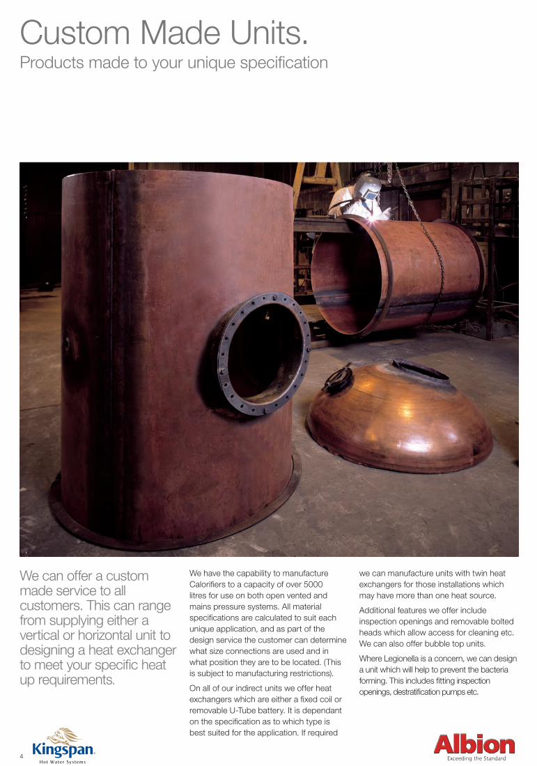
Custom Made Units.Products made to your unique specification
We can offer a custom made service to all customers. This can range from supplying either a vertical or horizontal unit to designing a heat exchanger to meet your specific heat up requirements.
We have the capability to manufacture Calorifiers to a capacity of over 5000 litres for use on both open vented and mains pressure systems. All material specifications are calculated to suit each unique application, and as part of the design service the customer can determine what size connections are used and in what position they are to be located. (This is subject to manufacturing restrictions).
On all of our indirect units we offer heat exchangers which are either a fixed coil or removable U-Tube battery. It is dependant on the specification as to which type is best suited for the application. If required
we can manufacture units with twin heat exchangers for those installations which may have more than one heat source.
Additional features we offer include inspection openings and removable bolted heads which allow access for cleaning etc. We can also offer bubble top units.
Where Legionella is a concern, we can design a unit which will help to prevent the bacteria forming. This includes fitting inspection openings, destratification pumps etc.
4
Commercial Industrial brochure Artwork -v4.indd 5 24/7/08 23:01:31
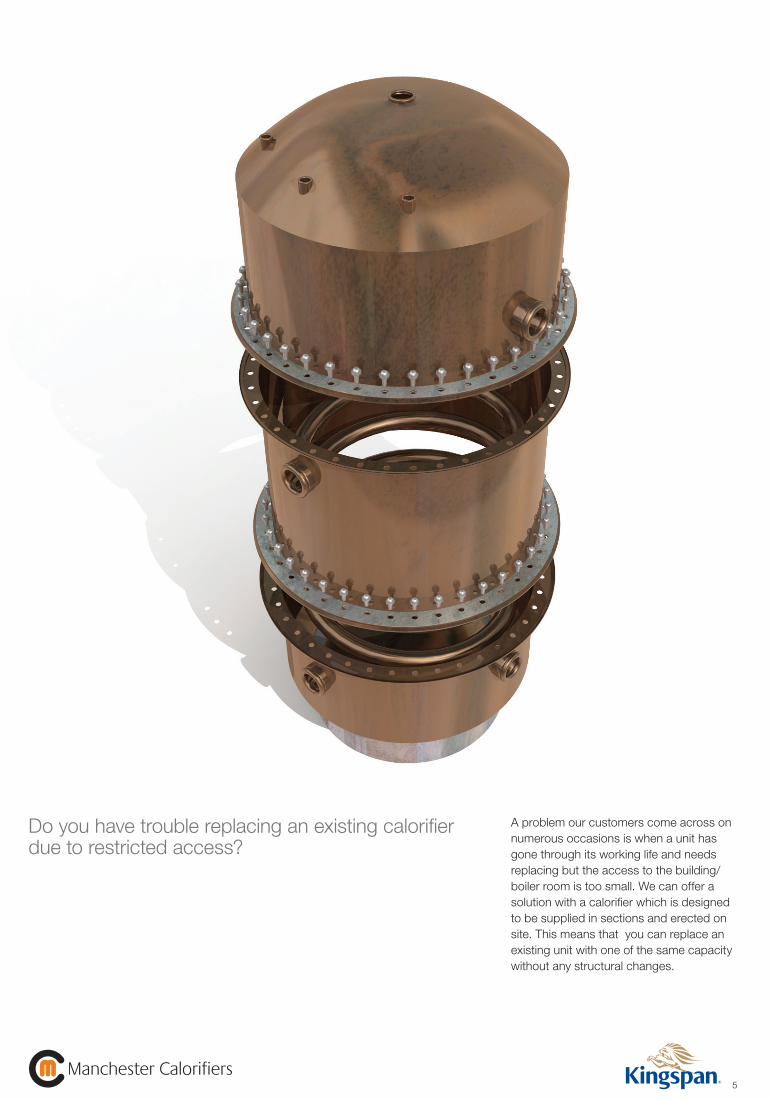
A problem our customers come across on numerous occasions is when a unit has gone through its working life and needs replacing but the access to the building/ boiler room is too small. We can offer a solution with a calorifier which is designed to be supplied in sections and erected on site. This means that you can replace an existing unit with one of the same capacity without any structural changes.
5Manchester Calorifiers
Manchester Calorifiers
Do you have trouble replacing an existing calorifier due to restricted access?
Commercial Industrial brochure Artwork -v4.indd 6 24/7/08 23:01:33
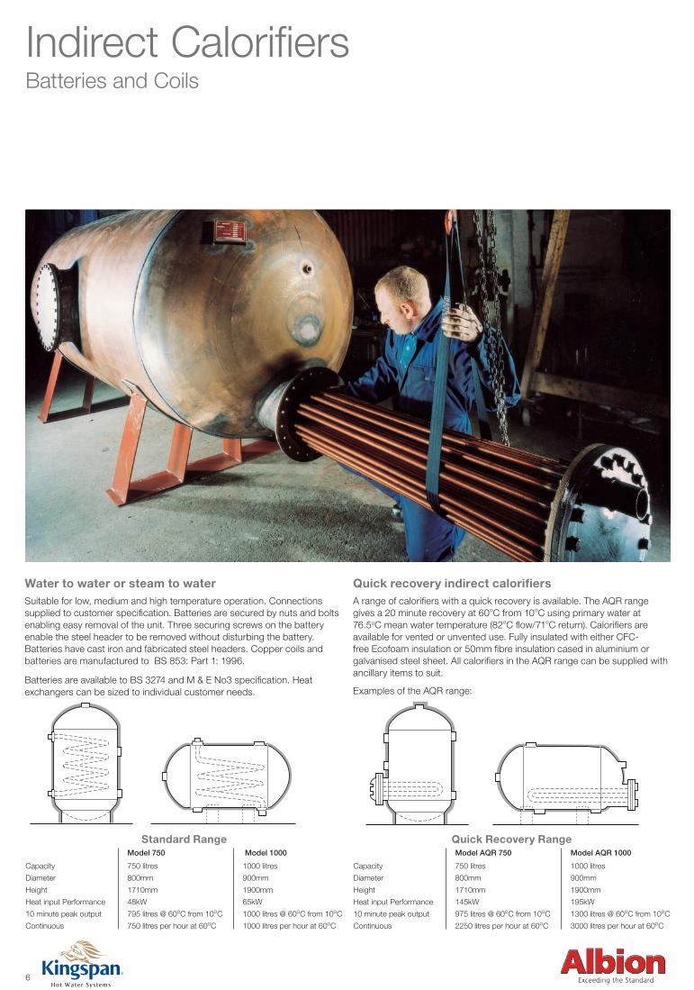
Indirect CalorifiersBatteries and Coils
Quick recovery indirect calorifiersA range of calorifiers with a quick recovery is available. The AQR range gives a 20 minute recovery at 60oC from 10oC using primary water at 76.5oC mean water temperature (82oC flow/71oC return). Calorifiers are available for vented or unvented use. Fully insulated with either CFC-free Ecofoam insulation or 50mm fibre insulation cased in aluminium or galvanised steel sheet. All calorifiers in the AQR range can be supplied with ancillary items to suit.
Examples of the AQR range:
Water to water or steam to waterSuitable for low, medium and high temperature operation. Connections supplied to customer specification. Batteries are secured by nuts and bolts enabling easy removal of the unit. Three securing screws on the battery enable the steel header to be removed without disturbing the battery. Batteries have cast iron and fabricated steel headers. Copper coils and batteries are manufactured to BS 853: Part 1: 1996.
Batteries are available to BS 3274 and M & E No3 specification. Heat exchangers can be sized to individual customer needs.
Model AQR 750 Model AQR 1000
Capacity 750 litres 1000 litres
Diameter 800mm 900mm
Height 1710mm 1900mm
Heat input Performance 145kW 195kW
10 minute peak output 975 litres @ 60oC from 10oC 1300 litres @ 60oC from 10oC
Continuous 2250 litres per hour at 60oC 3000 litres per hour at 60oC
Model 750 Model 1000
Capacity 750 litres 1000 litres
Diameter 800mm 900mm
Height 1710mm 1900mm
Heat input Performance 48kW 65kW
10 minute peak output 795 litres @ 60oC from 10oC 1000 litres @ 60oC from 10oC
Continuous 750 litres per hour at 60oC 1000 litres per hour at 60oC
6
Standard Range Quick Recovery Range
Commercial Industrial brochure Artwork -v4.indd 7 24/7/08 23:01:45
Model AQR 750 Model AQR 1000
Capacity 750 litres 1000 litres
Diameter 800mm 900mm
Height 1710mm 1900mm
Heat input Performance 145kW 195kW
10 minute peak output 975 litres @ 60oC from 10oC 1300 litres @ 60oC from 10oC
Continuous 2250 litres per hour at 60oC 3000 litres per hour at 60oC
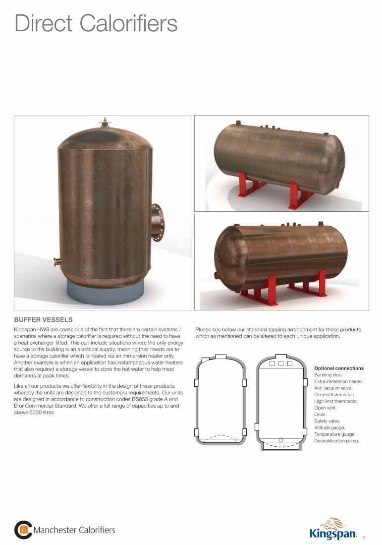
Direct Calorifiers
7Manchester Calorifiers
Manchester Calorifiers
BUFFER VESSELSKingspan HWS are conscious of the fact that there are certain systems / scenarios where a storage calorifier is required without the need to have a heat exchanger fitted. This can include situations where the only energy source to the building is an electrical supply, meaning their needs are to have a storage calorifier which is heated via an immersion heater only. Another example is when an application has instantaneous water heaters that also required a storage vessel to store the hot water to help meet demands at peak times.
Like all our products we offer flexibility in the design of these products whereby the units are designed to the customers requirements. Our units are designed in accordance to construction codes BS853 grade A and B or Commercial Standard. We offer a full range of capacities up to and above 5000 litres.
Please see below our standard tapping arrangement for these products which as mentioned can be altered to each unique application.
Optional connectionsBursting disc.Extra immersion heater.Anti vacuum valve.Control thermostat.High limit thermostat.Open vent.Drain.Safety valve.Altitude gauge.Temperature gaugeDestratification pump.
61
2
3
4
5 5
4
6
7 2
3
8 9
1
10
61
2
3
4
5 5
4
6
7 2
3
8 9
1
10
Commercial Industrial brochure Artwork -v4.indd 8 24/7/08 23:02:00
9Manchester Calorifiers
Manchester Calorifiers
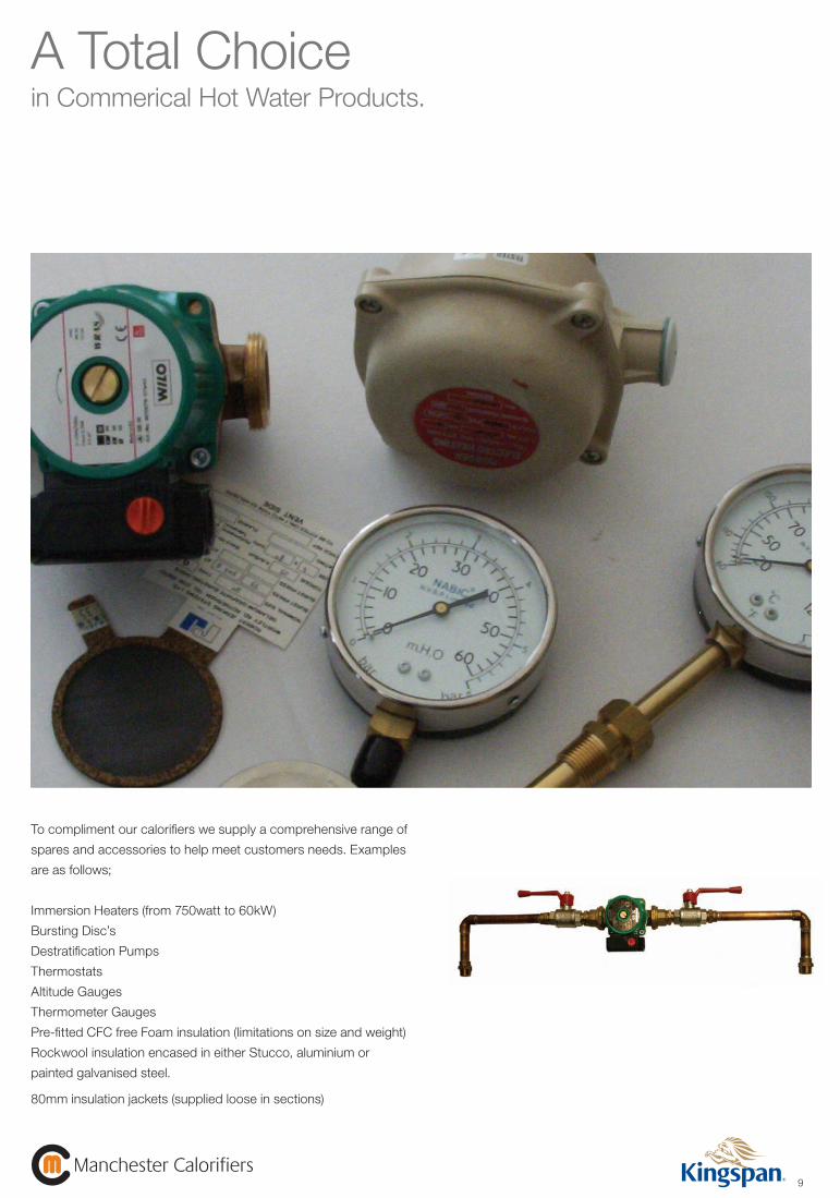
A Total Choicein Commerical Hot Water Products.
To compliment our calorifiers we supply a comprehensive range of
spares and accessories to help meet customers needs. Examples
are as follows;
Immersion Heaters (from 750watt to 60kW)
Bursting Disc’s
Destratification Pumps
Thermostats
Altitude Gauges
Thermometer Gauges
Pre-fitted CFC free Foam insulation (limitations on size and weight)
Rockwool insulation encased in either Stucco, aluminium or
painted galvanised steel.
80mm insulation jackets (supplied loose in sections)
Commercial Industrial brochure Artwork -v4.indd 10 25/7/08 08:03:49
Hot Water Storage Calorifiersavailable in Copper, Stainless, Galvanised and Mild Steel.
GeneralMaterials of construction are generally in accordance with the relevant British Standard Code of Practice. British Standards applicable to cylinder construction are codes 853 (Grade A or B). Vertical pattern units are fitted with either a ringstand or three leg mild steel stand (where applicable). Horizontal type units have rubber lined mild steel cradles, supplied loose for customer location.
Shell materialCopper is the ideal material to use with potable water because of its non-corrosive properties. The material thickness (therefore cost) is relative to the shell working pressure (head), and this must be stated at enquiry stage. Alternatives (such as stainless steel) are available particularly for large capacities and working pressuresabove 6.00 bar. Mild steel (Galvanised after manufacture) is available for particularly hard water conditions.
Primary heaterConstructed in the form of U-tubes containing extended surface copper tubes, roller expanded into a non ferrous tubeplate. Each unit is sized to specific requirements and can be adapted to suit water, steam and other heating mediums. Primary headers would be constructed from either cast iron or mild steel (fabricated).
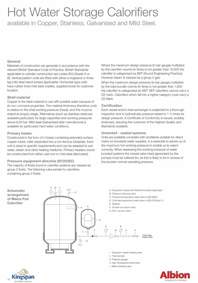
Pressure equipment directive (97/23/EC)The majority of fluids found in calorifier systems are classed asgroup 2 fluids. The following rules pertain to calorifierscontaining group 2 fluids:
Where the maximum design pressure (in bar gauge) multipliedby the calorifier volume (in litres) is not greater than 10,000 thecalorifier is categorised as SEP (Sound Engineering Practice).However steam is classed as a group 2 gas:
When the maximum design pressure (in bar gauge) multipliedby the tube bundle volume (in litres) is not greater than 1,000the calorifier is categorised as SEP. SEP calorifiers cannot carry a CE mark. Calorifiers which fall into a higher category must carry a CE Mark
CertificationEach vessel and/or heat exchanger is subjected to a thoroughinspection and is hydraulically pressure tested to 1 ½ times itsdesign pressure. A Certificate of Conformity is issued, suitablyendorsed, assuring the customer of the Highest Quality andStandards available.
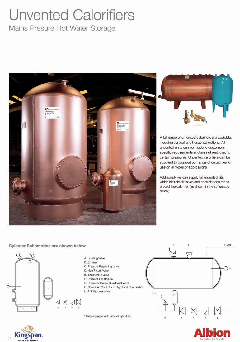
Unvented - sealed systemsUnits are available complete with ancillaries suitable for directmains (or boosted) water supplies. It is essential to advise us ofthe maximum hot working pressure to enable us to selectcorrectly. When assessing the working pressure of waterboosted systems the closed valve head (generated by thepumps) must be catered for, as this is likely to be in excess ofthe booster normal operating pressure.
10
iii iiG
C
iv
A
IF B E V
D
iii iii
Cold watersupply pipe
iv
Expansion vessel with fixed/removeable diaphragmA.
Pressure reducing valveB.
Pressure/temperature relief valve to (BS 6283)C.
Cold feed (expansion) relief valve to (BS 6759 part 1)D.
StrainerE.
Double non return valveF.
Anti -vacuum valveG.
Schematic arrangement of Mains Fed Calorifier
i Expansion vessel isolating valve
ii Thermometer
iii Pressure gauges
iv High Temperature thermostat
v Mains Isolating valve
Commercial Industrial brochure Artwork -v4.indd 11 24/7/08 23:02:21
11Manchester Calorifiers
Manchester Calorifiers
B
*
A
A B
F
IN
BatteryRemoval
OUT
IN
OUT
BatteryRemoval
C
E
D
TYPE HU
E
D
C
F
Approx190mm
TYPE VU
B
*
A
A B
F
IN
BatteryRemoval
OUT
IN
OUT
BatteryRemoval
C
E
D
TYPE HU
E
D
C
F
Approx190mm
TYPE VU
B
*
A
A B
F
IN
BatteryRemoval
OUT
IN
OUT
BatteryRemoval
C
E
D
TYPE HU
E
D
C
F
Approx190mm
TYPE VU
B
*
A
A B
F
IN
BatteryRemoval
OUT
IN
OUT
BatteryRemoval
C
E
D
TYPE HU
E
D
C
F
Approx190mm
TYPE VU
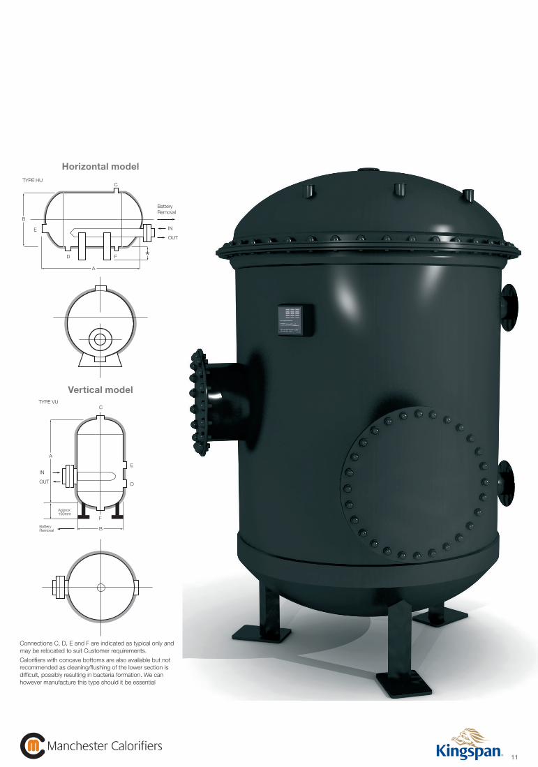
Connections C, D, E and F are indicated as typical only and may be relocated to suit Customer requirements.
Calorifiers with concave bottoms are also available but not recommended as cleaning/flushing of the lower section is difficult, possibly resulting in bacteria formation. We can however manufacture this type should it be essential
Vertical model
Horizontal model
Commercial Industrial brochure Artwork -v4.indd 12 24/7/08 23:02:24
12
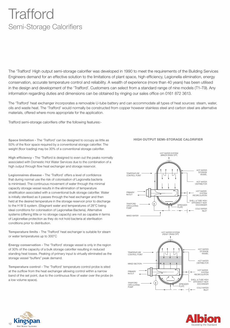
TraffordSemi-Storage Calorifiers
The ‘Trafford’ High output semi-storage calorifier was developed in 1990 to meet the requirements of the Building Services Engineers demand for an effective solution to the limitations of plant space, high efficiency, Legionella elimination, energy conservation, accurate temperature control and reliability. A wealth of experience (more than 40 years) has been utilised in the design and development of the ‘Trafford’. Customers can select from a standard range of nine models (T1–T9). Any information regarding duties and dimensions can be obtained by ringing our sales office on 0161 872 3613.
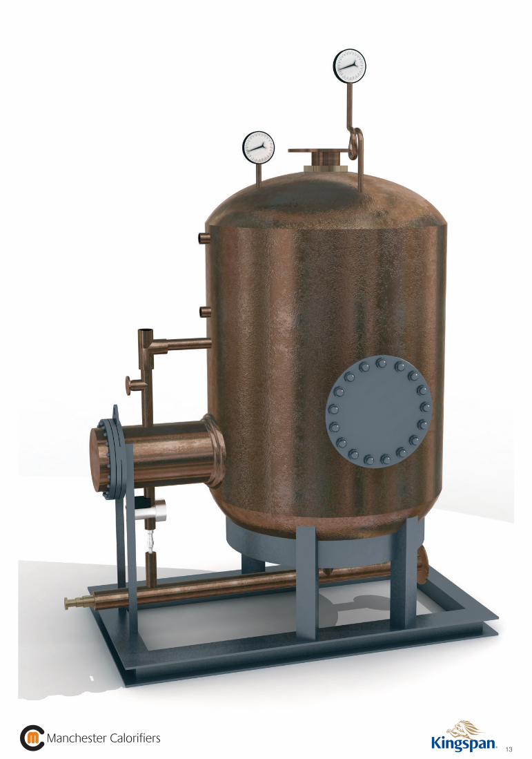
The ‘Trafford’ heat exchanger incorporates a removable U-tube battery and can accommodate all types of heat sources: steam, water, oils and waste heat. The ‘Trafford’ would normally be constructed from copper however stainless steel and carbon steel are alternative materials, offered where more appropriate for the application.
Trafford semi-storage calorifiers offer the following features:-
Space limitation - The ‘Trafford’ can be designed to occupy as little as 50% of the floor space required by a conventional storage calorifier. The weight (floor loading) may be 30% of a conventional storage calorifier.
High efficiency - The ‘Trafford is designed to even out the peaks normally associated with Domestic Hot Water Services due to the combination of a high output through flow heat exchanger and storage reservoir.
Legionnaires disease - The ‘Trafford’ offers a level of confidence that during normal use the risk of colonisation of Legionella bacteria is minimised. The continuous movement of water through the minimal capacity storage vessel results in the elimination of temperature stratification associated with a conventional bulk storage calorifier. Water is initially sterilised as it passes through the heat exchanger and then held at the desired temperature in the storage reservoir prior to discharge to the H W S system. (Stagnant water and temperatures of 28oC being ideal conditions for colonisation of Legionellae Bacteria). Alternative systems (offering little or no storage capacity) are not as capable in terms of Legionellae protection as they do not hold bacteria at sterilisation conditions prior to distribution.
Temperature limits - The ‘Trafford’ heat exchanger is suitable for steam or water temperatures up to 300oC
Energy conservation - The ‘Trafford’ storage vessel is only in the region of 30% of the capacity of a bulk storage calorifier resulting in reduced standing heat losses. Peaking of primary input is virtually eliminated as the storage vessel “buffers” peak demand.
Temperature control - The ‘Trafford’ temperature control probe is sited at the outflow from the heat exchanger allowing control within a narrow band of the set point, due to the continuous flow of water over the probe (in a low volume space).
TEMPERATURECONTROL POINT
HOT WATERSTORAGE
VESSEL
HOT WATERDISTRIBUTOR
HOT WATER SYSTEM
RECIRCULATION
SHELL & TUBE HIGHEFFICIENCY HEAT
EXCHANGER
COLD WATERINLET
PRIMARYIN/OUT
TRAFFORDCIRCULATINGPUMP
SPREADERPLATE
MIXED WATER
HOT WATER SYSTEM(MINOR DRAW OFF)
TEMPERATURECONTROL POINT
HOT WATERSTORAGE
VESSEL
HOT WATERDISTRIBUTOR
HOT WATER SYSTEM
RECIRCULATION
SHELL & TUBE HIGHEFFICIENCY HEAT
EXCHANGER
COLD WATERINLET
PRIMARYIN/OUT
MIXED SECTION
TRAFFORDCIRCULATINGPUMP
SPREADERPLATE
HOT WATER SYSTEM(HEAVY DRAW OFF)
TEMPERATURECONTROL POINT
HOT WATERSTORAGE
VESSEL
HOT WATERDISTRIBUTOR
HOT WATER SYSTEM
RECIRCULATION
SHELL & TUBE HIGHEFFICIENCY HEAT
EXCHANGER
COLD WATERINLET
PRIMARYIN/OUT
TRAFFORDCIRCULATINGPUMP
SPREADERPLATE
MIXED WATER
HOT WATER SYSTEM(MINOR DRAW OFF)
TEMPERATURECONTROL POINT
HOT WATERSTORAGE
VESSEL
HOT WATERDISTRIBUTOR
HOT WATER SYSTEM
RECIRCULATION
SHELL & TUBE HIGHEFFICIENCY HEAT
EXCHANGER
COLD WATERINLET
PRIMARYIN/OUT
MIXED SECTION
TRAFFORDCIRCULATINGPUMP
SPREADERPLATE
HOT WATER SYSTEM(HEAVY DRAW OFF)
HIGH OUTPUT SEMI-STORAGE CALORIFIER
Commercial Industrial brochure Artwork -v4.indd 13 24/7/08 23:02:25
13Manchester Calorifiers
Manchester Calorifiers
Commercial Industrial brochure Artwork -v4.indd 14 24/7/08 23:02:27
14
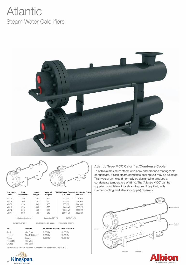
AtlanticSteam Water Calorifiers
Horizontal Shell Shell Overall OUTPUT (kW) Steam Pressure At Chest Unit Diameter* Length* Height* 1.50 Bar 3.00 Bar
MC 05 140 1200 355 100 kW 130 kW
MC 06 160 1200 415 270 kW 350 kW
MC 08 210 1500 460 600 kW 800 kW
MC 10 270 1500 525 1000 kW 1250 kW
MC 12 310 1500 565 1800 kW 2200 kW
MC 14 360 1500 640 2500 kW 3000 kW
*All dimensions in mm Secondary 82/71oC OUTPUT (kW)
Part Material Working Pressure Test Pressure
Shell Mild Steel 6.36 Bar 10.50 Bar
Header Ci or Mild Steel 6.36 Bar 10.50 Bar
Tubes Copper 6.36 Bar 10.50 Bar
Tubeplate Mild Steel
Cradles Mild Steel
For applications other than above refer to our sales office, Telephone:- 0161 872 3613
Atlantic Type MCC Calorifier/Condense CoolerTo achieve maximum steam efficiency and produce manageable condensate, a flash steam/condense cooling unit may be selected.This type of unit would normally be designed to produce a condensate temperature of 88 oC. The ‘Atlantic MCC’ can be supplied complete with a steam trap set if required, withinterconnecting mild steel (or copper) pipework.
STRAINER
SIGHT GLASS STEAM TRAP
CALORIFIER
CONDENSECOOLER
CONSTRUCTION CODE SHELL TO BS853 TUBES TO BS3274
Commercial Industrial brochure Artwork -v4.indd 15 24/7/08 23:02:31
15Manchester Calorifiers
Manchester Calorifiers
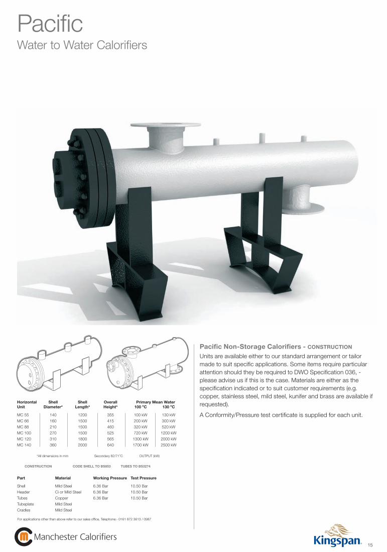
PacificWater to Water Calorifiers
Horizontal Shell Shell Overall Primary Mean Water Unit Diameter* Length* Height* 100 oC 130 oC
MC 55 140 1200 355 100 kW 130 kW
MC 66 160 1500 415 200 kW 300 kW
MC 88 210 1500 460 320 kW 520 kW
MC 100 270 1500 525 720 kW 1200 kW
MC 120 310 1800 565 1300 kW 2000 kW
MC 140 360 2000 640 1700 kW 2500 kW
*All dimensions in mm Secondary 82/71oC OUTPUT (kW)
Part Material Working Pressure Test Pressure
Shell Mild Steel 6.36 Bar 10.50 Bar
Header Ci or Mild Steel 6.36 Bar 10.50 Bar
Tubes Copper 6.36 Bar 10.50 Bar
Tubeplate Mild Steel
Cradles Mild Steel
For applications other than above refer to our sales office, Telephone:- 0161 872 3613 / 0987
CONSTRUCTION CODE SHELL TO BS853 TUBES TO BS3274
Pacific Non-Storage Calorifiers - CONSTRUCTION
Units are available either to our standard arrangement or tailor made to suit specific applications. Some items require particular attention should they be required to DWO Specification 036, - please advise us if this is the case. Materials are either as the specification indicated or to suit customer requirements (e.g. copper, stainless steel, mild steel, kunifer and brass are available if requested).
A Conformity/Pressure test certificate is supplied for each unit.
Commercial Industrial brochure Artwork -v4.indd 16 24/7/08 23:02:33
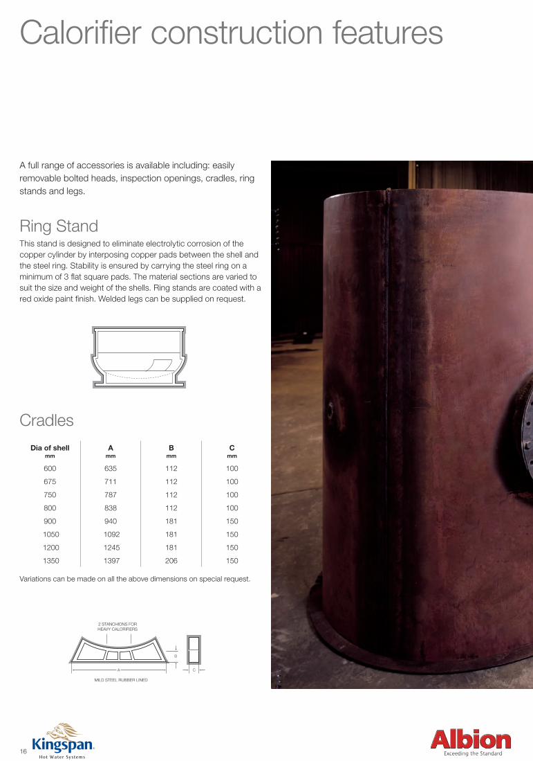
Cradles
Dia of shellmm
A mm
B mm
C mm
600 635 112 100
675 711 112 100
750 787 112 100
800 838 112 100
900 940 181 150
1050 1092 181 150
1200 1245 181 150
1350 1397 206 150
2 STANCHIONS FORHEAVY CALORIFIERS
MILD STEEL RUBBER LINED
B
A C
SHELL
NECK
COPPER LINEDSTEEL COVER
BOLTS
BACKINGRING
JOINTRING
BACKINGRING
JOINTRING
BACKINGRING
BOLTS
TOP OF CYLINDER
Calorifier construction features
A full range of accessories is available including: easily removable bolted heads, inspection openings, cradles, ring stands and legs.
Ring StandThis stand is designed to eliminate electrolytic corrosion of the copper cylinder by interposing copper pads between the shell and the steel ring. Stability is ensured by carrying the steel ring on a minimum of 3 flat square pads. The material sections are varied to suit the size and weight of the shells. Ring stands are coated with a red oxide paint finish. Welded legs can be supplied on request.
Variations can be made on all the above dimensions on special request.
2 STANCHIONS FORHEAVY CALORIFIERS
MILD STEEL RUBBER LINED
B
A C
SHELL
NECK
COPPER LINEDSTEEL COVER
BOLTS
BACKINGRING
JOINTRING
BACKINGRING
JOINTRING
BACKINGRING
BOLTS
TOP OF CYLINDER
16
Commercial Industrial brochure Artwork -v4.indd 17 24/7/08 23:02:41
17Manchester Calorifiers
Manchester Calorifiers
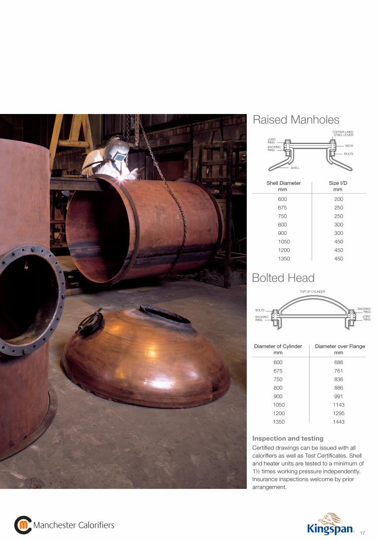
Inspection and testingCertified drawings can be issued with all calorifiers as well as Test Certificates. Shell and heater units are tested to a minimum of 1½ times working pressure independently. Insurance inspections welcome by prior arrangement.
Raised Manholes
Bolted Head
Shell Diameter Size I/D mm mm
600 200
675 250
750 250
800 300
900 300
1050 450
1200 450
1350 450
2 STANCHIONS FORHEAVY CALORIFIERS
MILD STEEL RUBBER LINED
B
A C
SHELL
NECK
COPPER LINEDSTEEL COVER
BOLTS
BACKINGRING
JOINTRING
BACKINGRING
JOINTRING
BACKINGRING
BOLTS
TOP OF CYLINDER
Diameter of Cylinder Diameter over Flange mm mm
600 686
675 761
750 836
800 886
900 991
1050 1143
1200 1295
1350 1443
2 STANCHIONS FORHEAVY CALORIFIERS
MILD STEEL RUBBER LINED
B
A C
SHELL
NECK
COPPER LINEDSTEEL COVER
BOLTS
BACKINGRING
JOINTRING
BACKINGRING
JOINTRING
BACKINGRING
BOLTS
TOP OF CYLINDER
Commercial Industrial brochure Artwork -v4.indd 18 24/7/08 23:02:47
18
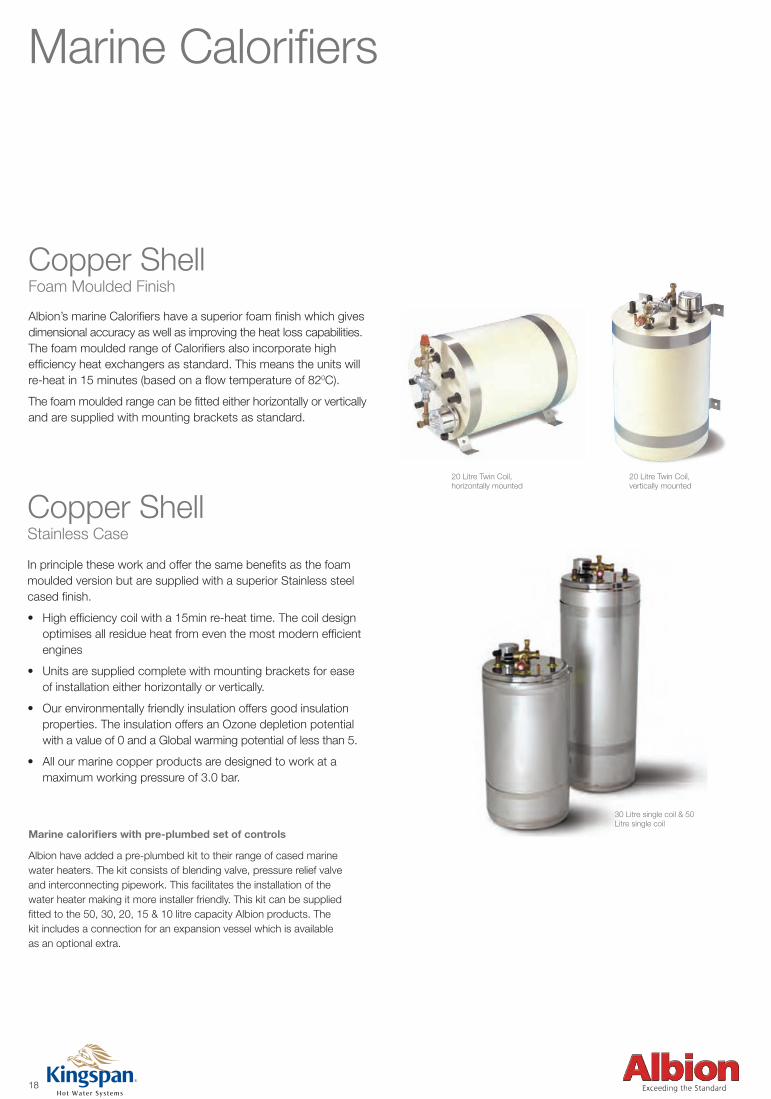
Marine Calorifiers
Albion’s marine Calorifiers have a superior foam finish which gives dimensional accuracy as well as improving the heat loss capabilities. The foam moulded range of Calorifiers also incorporate high efficiency heat exchangers as standard. This means the units will re-heat in 15 minutes (based on a flow temperature of 820C).
The foam moulded range can be fitted either horizontally or vertically and are supplied with mounting brackets as standard.
Copper Shell Foam Moulded Finish
20 Litre Twin Coil, vertically mounted
20 Litre Twin Coil, horizontally mounted
In principle these work and offer the same benefits as the foam moulded version but are supplied with a superior Stainless steel cased finish.
• Highefficiencycoilwitha15minre-heattime.Thecoildesign optimises all residue heat from even the most modern efficient engines
• Unitsaresuppliedcompletewithmountingbracketsforease of installation either horizontally or vertically.
• Ourenvironmentallyfriendlyinsulationoffersgoodinsulation properties. The insulation offers an Ozone depletion potential with a value of 0 and a Global warming potential of less than 5.
• Allourmarinecopperproductsaredesignedtoworkata maximum working pressure of 3.0 bar.
Copper ShellStainless Case
30 Litre single coil & 50 Litre single coil
Marine calorifiers with pre-plumbed set of controls
Albion have added a pre-plumbed kit to their range of cased marine water heaters. The kit consists of blending valve, pressure relief valve and interconnecting pipework. This facilitates the installation of the water heater making it more installer friendly. This kit can be supplied fitted to the 50, 30, 20, 15 & 10 litre capacity Albion products. The kit includes a connection for an expansion vessel which is available as an optional extra.
Commercial Industrial brochure Artwork -v4.indd 19 24/7/08 23:02:49
19Manchester Calorifiers
Manchester Calorifiers
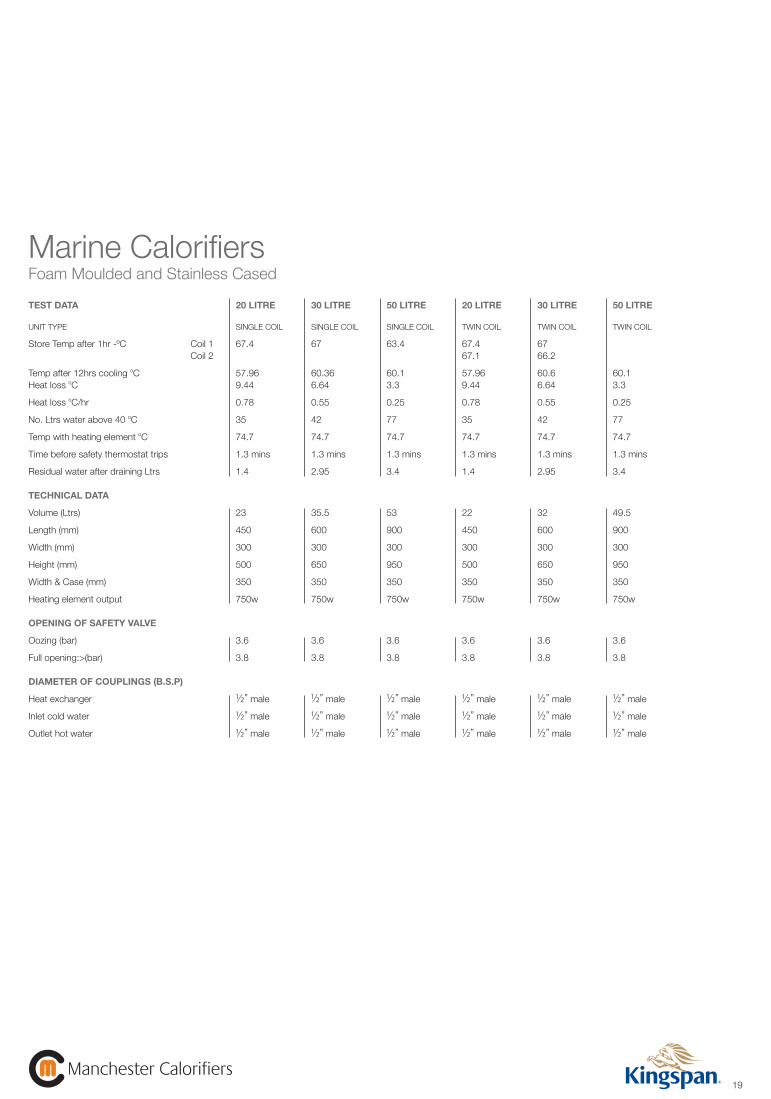
TEST DATA 20 LITRE 30 LITRE 50 LITRE 20 LITRE 30 LITRE 50 LITRE
UNIT TYPE SINGLE COIL SINGLE COIL SINGLE COIL TWIN COIL TWIN COIL TWIN COIL
Store Temp after 1hr -ºC Coil 1 67.4 67 63.4 67.4 67 Coil 2 67.1 66.2
Temp after 12hrs cooling oC 57.96 60.36 60.1 57.96 60.6 60.1Heat loss oC 9.44 6.64 3.3 9.44 6.64 3.3
Heat loss oC/hr 0.78 0.55 0.25 0.78 0.55 0.25
No. Ltrs water above 40 oC 35 42 77 35 42 77
Temp with heating element oC 74.7 74.7 74.7 74.7 74.7 74.7
Time before safety thermostat trips 1.3 mins 1.3 mins 1.3 mins 1.3 mins 1.3 mins 1.3 mins
Residual water after draining Ltrs 1.4 2.95 3.4 1.4 2.95 3.4
TECHNICAL DATA
Volume (Ltrs) 23 35.5 53 22 32 49.5
Length (mm) 450 600 900 450 600 900
Width (mm) 300 300 300 300 300 300
Height (mm) 500 650 950 500 650 950
Width & Case (mm) 350 350 350 350 350 350
Heating element output 750w 750w 750w 750w 750w 750w
OPENING OF SAFETY VALVE
Oozing (bar) 3.6 3.6 3.6 3.6 3.6 3.6
Full opening:>(bar) 3.8 3.8 3.8 3.8 3.8 3.8
DIAMETER OF COUPLINGS (B.S.P)
Heat exchanger 1/2” male 1/2” male 1/2” male 1/2” male 1/2” male 1/2” male
Inlet cold water 1/2” male 1/2” male 1/2” male 1/2” male 1/2” male 1/2” male
Outlet hot water 1/2” male 1/2” male 1/2” male 1/2” male 1/2” male 1/2” male
Marine CalorifiersFoam Moulded and Stainless Cased
Commercial Industrial brochure Artwork -v4.indd 20 24/7/08 23:02:50
20
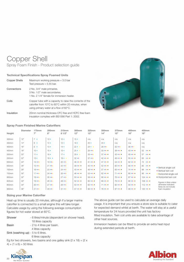
Copper Shell Spray Foam Finish - Product selection guide
Technical Specifications Spray Foamed Units
Copper Shells Maximum working pressure = 3.0 bar Test pressure = 5.55 bar.
Connections 2 No. 3/4” male primaries. 3 No. 1/2” male secondaries. 1 No. 2 1/4” female for immersion heater.
Coils Copper tube with a capacity to raise the contents of the calorifier from 10°C to 60°C within 20 minutes, when using primary water at a flow of 82°C.
Insulation 20mm nominal thickness CFC free and HCFC free foam insulation complies with BS1566 Part 1: 2002.
• Vertical single coil • Vertical twin coil • Horizontal single coil • Horizontal twin coil Figures in litres unless otherwise indicated. Sizes do not include foam insulation
Diameter 175mm 200mm 210mm 300mm 325mm 350mm 375mm 400mm 450mmHeight 7” 8” 8 1/2” 12” 13” 14” 15” 16” 18”
300mm 12” 7 • 10 • 10 • 15 • n/a n/a n/a n/a n/a
350mm 14” 8 • 12 • 12 • 18 • 20 • ••• 23 • ••• n/a n/a n/a
400mm 16” 9 • 13 • 14 • 22 • • • 24 • • • • 28 • • • • 32 • • • • 36 • • • • n/a
450mm 18” 10 • 15 • 15 • 25 • •• 29 • • • • 33 • • •• 38• • •• 43• • •• 52 • • ••
500mm 20” 11 • 16 • 17 • 29 • • • 33 • • • • 37 • • •• 43• • •• 49• • •• 57 • • ••
550mm 22” 13 • 18 • • 19 • • • 32 • • •• 37 • • • • 42 • • •• 49• • •• 55• • •• 65 • • ••
600mm 24” 14 • • • 19 • • • 20 • • • 36 • • •• 41• • •• 47• • •• 54• • •• 62• • •• 72 • • ••
650mm 26” 15 • • • 21 • • • 22 • • • 39 • • •• 45• • •• 52• • •• 60• • •• 68• • •• 80 • • ••
700mm 28” 16 • • • 23 • • • 24 • • • 43 • • •• 49• • •• 57• • •• 65• • •• 74• • •• 88 • • ••
750mm 30” 17 • • • 24 • • • 26 • • • 46 • • •• 53• • •• 62• • •• 71• • •• 80• • •• 96 • • ••
800mm 32” 19 • • • 26 • • • 27 • • • 50 • • •• 58• • •• 66• • •• 76• • •• 87• • •• 104• • ••
825mm 33” 19 • • • 26 • • • 28 • • • 52 • • •• 60• • •• 69• • •• 79• • •• 90• • •• 108• • ••
850mm 34” 20 • • • 27 • • • 29 • • • 53 • • •• 62• • •• 71• • •• 82• • •• 93• • •• 112• • ••
900mm 36” 21 • • • 29 • • • 31 • • • 57 • • •• 66• • •• 76• • •• 87• • •• 99• • •• 120• • ••
Spray Foam Finished Marine Calorifiers
Sizing your Marine Calorifier
Heat-up time is usually 20 minutes, although if a larger marinecalorifier is connected to a small engine this will take longer.Calculate usage by using the following average consumptionfigures for hot water stored at 60°C.
Shower - 6 litres/minute (dependent on shower head). 18 litres capacityBasin - 2 to 4 litres per basin. 4 litres capacitySink (washing up) - 5 to 6 litres. 6 litres capacityEg for two showers, two basins and one galley sink (2 x 18) + (2 x 4) + (1 x 6) = 50 litres
The above guide can be used to calculate an average daily usage. It is important that you ensure a store size is suitable to cater for expected demand whilst at berth. The water will stay at a useful temperature for 24 hours provided the unit has factoryfitted insulation. Twin coil units are available to take advantage of other heat sources.
Immersion heaters can be fitted to provide an extra heat inputduring extended periods at berth.
Commercial Industrial brochure Artwork -v4.indd 21 24/7/08 23:02:55
21Manchester Calorifiers
Manchester Calorifiers
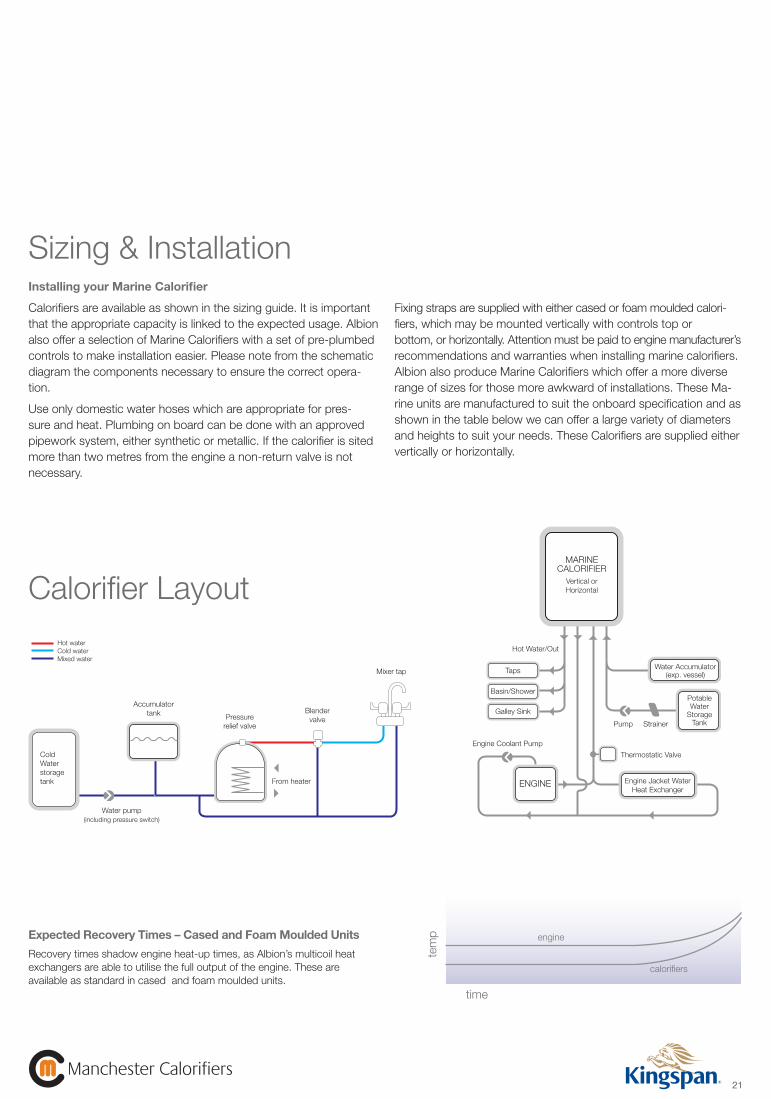
Installing your Marine Calorifier
Calorifiers are available as shown in the sizing guide. It is important that the appropriate capacity is linked to the expected usage. Albion also offer a selection of Marine Calorifiers with a set of pre-plumbed controls to make installation easier. Please note from the schematic diagram the components necessary to ensure the correct opera-tion.
Use only domestic water hoses which are appropriate for pres-sure and heat. Plumbing on board can be done with an approved pipework system, either synthetic or metallic. If the calorifier is sited more than two metres from the engine a non-return valve is not necessary.
Fixing straps are supplied with either cased or foam moulded calori-fiers, which may be mounted vertically with controls top orbottom, or horizontally. Attention must be paid to engine manufacturer’s recommendations and warranties when installing marine calorifiers. Albion also produce Marine Calorifiers which offer a more diverse range of sizes for those more awkward of installations. These Ma-rine units are manufactured to suit the onboard specification and as shown in the table below we can offer a large variety of diameters and heights to suit your needs. These Calorifiers are supplied either vertically or horizontally.
Sizing & Installation
ColdWaterstoragetank
Accumulatortank
Water pump(including pressure switch)
Pressurerelief valve
Blendervalve
From heater
Mixer tap Taps
MARINECALORIFIER
Vertical orHorizontal
Basin/Shower
Galley Sink
Engine Coolant Pump
Thermostatic Valve
Engine Jacket WaterHeat Exchanger
Water Accumulator(exp. vessel)
PotableWater
StorageTank
ENGINE
Pump Strainer
Hot Water/Out
Expected Recovery Times – Cased and Foam Moulded Units
Recovery times shadow engine heat-up times, as Albion’s multicoil heat exchangers are able to utilise the full output of the engine. These are available as standard in cased and foam moulded units.
time
tem
p engine
calorifiers
Calorifier LayoutHot waterCold waterMixed water
Commercial Industrial brochure Artwork -v4.indd 22 24/7/08 23:02:57
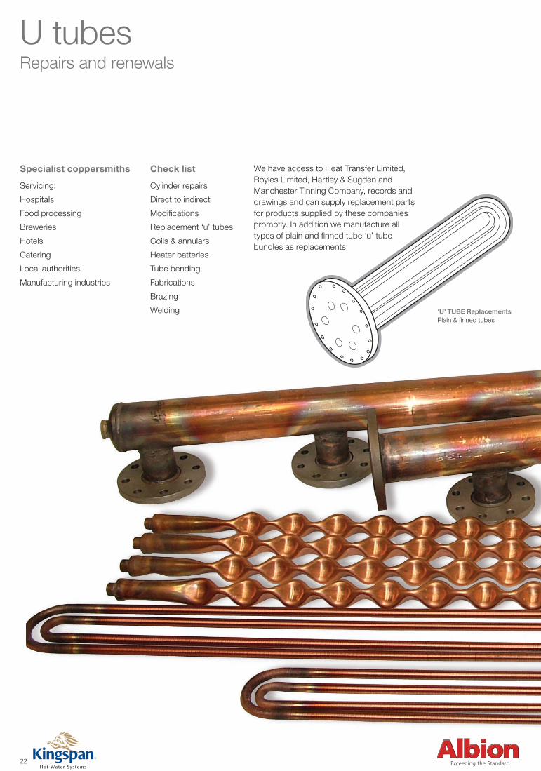
U tubesRepairs and renewals
Specialist coppersmiths
Servicing:
Hospitals
Food processing
Breweries
Hotels
Catering
Local authorities
Manufacturing industries
‘U’ TUBE ReplacementsPlain & finned tubes
We have access to Heat Transfer Limited, Royles Limited, Hartley & Sugden and Manchester Tinning Company, records and drawings and can supply replacement parts for products supplied by these companies promptly. In addition we manufacture all types of plain and finned tube ‘u’ tube bundles as replacements.
Check list
Cylinder repairs
Direct to indirect
Modifications
Replacement ‘u’ tubes
Coils & annulars
Heater batteries
Tube bending
Fabrications
Brazing
Welding
22
Commercial Industrial brochure Artwork -v4.indd 23 24/7/08 23:03:01
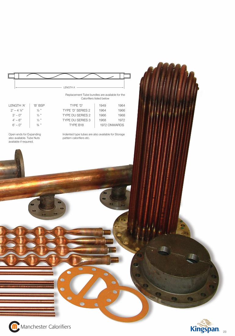
LENGTH A
LENGTH ‘A’ ‘B’ BSP
2’ – 4 ¼” ½ ”
3’ – 0” ½ ”
4’ – 6” ½ ”
6’ – 0” ¾ ”
Open ends for Expanding also available. Tube Nutsavailable if required.
TYPE ‘D’ 1949 1964
TYPE ‘D’ SERIES 2 1964 1966
TYPE DU SERIES 2 1966 1968
TYPE DU SERIES 3 1968 1972
TYPE B18 1972 ONWARDS
Indented type tubes are also available for Storage pattern calorifiers etc.
Replacement Tube bundles are available for the Calorifiers listed below
23Manchester Calorifiers
Manchester Calorifiers
Commercial Industrial brochure Artwork -v4.indd 24 24/7/08 23:03:03
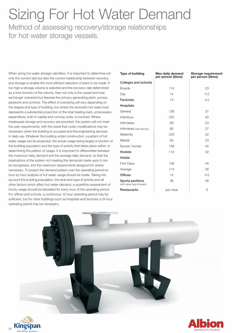
Sizing For Hot Water Demand Method of assessing recovery/storage relationships for hot water storage vessels.
When sizing hot water storage calorifiers, it is important to determine not
only the correct size but also the correct relationship between recovery
and storage to enable the most efficient selection of plant to be made. If
too high a storage volume is selected and the recovery rate determined
as a time function of the volume, then not only is the vessel and heat
exchanger oversized but likewise the primary generating plant, pumps,
pipework and controls. The effect of oversizing will vary depending on
the degree and type of building, but where the domestic hot water load
represents a substantial proportion of the total heating load, unnecessary
expenditure, both in capital and running costs, is involved. Where
inadequate storage and recovery are provided, the system will not meet
the user requirements, with the result that costly modifications may be
necessary when the building is occupied and the engineering services
in daily use. Whatever the building under construction, a pattern of hot
water usage can be projected, the actual usage being largely a function of
the building population and the type of activity that takes place within. In
determining the pattern of usage, it is important to differentiate between
the maximum daily demand and the average daily demand, so that the
implications of the system not meeting the demands made upon it can
be recognised, and the maximum requirements designed for where
necessary. To project the demand pattern over the operating period an
hour by hour analysis of hot water usage should be made. Taking into
account the building population, the level and type of activity and all
other factors which affect hot water demand, a quantitive assessment of
hourly usage should be tabulated for every hour of the operating period.
For offices and schools, a continuous 12 hour operating period may be
sufficient, but for other buildings such as hospitals and factories a 24 hour
operating period may be necessary.
Type of building Max daily demand per person (litres)
Storage requirement per person (litres)
Colleges and schools
Boards 114 23
Day 14 4.5
Factories 14 4.5
Hospitals
General 136 27
Infectious 225 45
Infirmaries 68 23
Infirmaries (with laundry) 90 27
Maternity 225 32
Mental 90 23
Nurses’ homes 136 45
Hostels 114 32
Hotels
First Class 136 45
Average 114 36
Offices 14 4.5
Sports pavilions(with spray type showers)
36 36
Restaurants per meal 6
24
Commercial Industrial brochure Artwork -v4.indd 25 24/7/08 23:03:05
25Manchester Calorifiers
Manchester Calorifiers
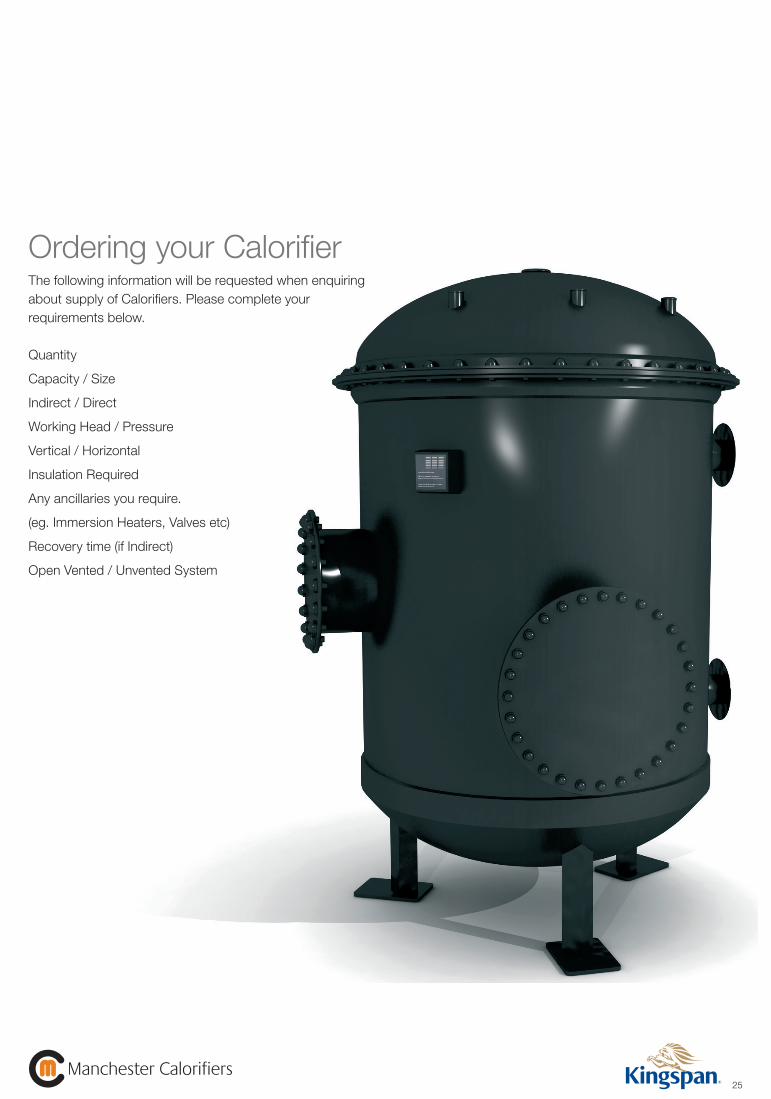
Ordering your CalorifierThe following information will be requested when enquiring about supply of Calorifiers. Please complete your requirements below.
Quantity
Capacity / Size
Indirect / Direct
Working Head / Pressure
Vertical / Horizontal
Insulation Required
Any ancillaries you require.
(eg. Immersion Heaters, Valves etc)
Recovery time (if Indirect)
Open Vented / Unvented System
Commercial Industrial brochure Artwork -v4.indd 26 24/7/08 23:03:07

Our credentialsWe have a long and distinguished history of supplying mechanical heating engineers with industrial and commercial calorofiers to meet a wide range of demands in varied environments. Outlined below are a sample section of our valued customer base developed over many years of successful trading.
WINDSOR CASTLE
BUCKINGHAM PALACE
WESTMINSTER ABBEY (CHOIR SCHOOL)
HOUSES OF PARLIAMENT
MANCHESTER UNIVERSITY
READING UNIVERSITY
WINCHESTER COLLEGE
LOUGHBOROUGH UNIVERSITY
ROYAL HOLLOWAY UNIVERSITY
SALFORD UNIVERSITY
IMPERIAL COLLEGE, LONDON
CADBURYS LIMITED
TREBOR BASSETT LIMITED
BURTONWOOD BREWERY
PLANET HOLLYWOOD
TOTTENHAM HOTSPUR F.C.
MANCHESTER UNITED F.C.
DAVID LLOYD LEISURE CENTRES
OXFORD UNITED F.C.
IPSWICH TOWN F.C.
HADEN YOUNG LIMITED U.K
A.E. TECHNOLOGY
N G BAILEY & CO LIMITED
SULZER INFRA (U.K) LIMITED
MANCHESTER ROYAL INFIRMARY
WITHINGTON HOSPITAL, MANCHESTER
SOUTHPORT GENERAL HOSPITAL
WYTHENSHAWE HOSPITAL, MANCHESTER
LEIGHTON HOSPITAL, CREWE
SOUTH SHIELDS GENERAL HOSPITAL
QUEEN ELIZABETH HOSPITAL, BIRMINGHAM
CARLISLE INFIRMARY
FAZAKERLEY HOSPITAL, LIVERPOOL
CAMERON HOSPITAL, FIFE
QUEEN’S MEDICAL CENTRE, NOTTINGHAM
NOTTINGHAM CITY HOSPITAL
ADDENBROOKS HOSPITAL
CHRISTIE HOSPITAL, MANCHESTER
NORTHERN GENERAL HOSPITAL, SHEFFIELD
LEEDS GENERAL INFIRMARY
ROYAL LIVERPOOL HOSPITAL
MATER HOSPITAL, BELFAST
DORCHESTER HOTEL
TRAVEL LODGE HOTELS
GROSVENOR HOUSE HOTEL
DE VERE HOTELS
BRITTANIA HOTELS
MOAT HOUSE HOTELS
TRUST HOUSE FORTE
HILTON HOTEL
CO-OPERATIVE INSURANCE SOCIETY H.Q
LE PAIN CROUSTILLIAN LIMITED
HALIFAX BUILDING SOCIETY H.Q
PRINCESS FOODS
BANK OF ENGLAND
CONVENIENCE FOODS LTD
KELLOGGS
MARKS AND SPENCER PLC
J SAINSBURY PLC
DUNNES STORES
BOOTHS SUPERMARKETS
ROYAL ARMOURIES MUSEUM, LEEDS
MANCHESTER AIRPORT
GATWICK AIRPORT
MANCHESTER CITY COUNCIL
SHROPSHIRE COUNTY COUNCIL
HEATHROW AIRPORT
TRAFFORD M.B.C
ROLLS ROYCE PLC
FORMICA LIMITED, SOUTH SHIELDS
DU PONT (U.K) LIMITED
ZENECA
H.M. PRISONS
PFIZER LIMITED
SHELL (U.K) STANLOW
INSTITUTE FOR ANIMAL HEALTH
NATURAL HISTORY MUSEUM, LONDON
26
Commercial Industrial brochure Artwork -v4.indd 27 24/7/08 23:03:08

Notes
27Manchester Calorifiers
Manchester Calorifiers
Commercial Industrial brochure Artwork -v4.indd 28 24/7/08 23:03:08