how higher chilled water temperature can improve data ... · units and returning to the chiller....
TRANSCRIPT

How Higher Chilled Water Temperature Can Improve Data Center Cooling System Efficiency
Executive summary Alternative data center cooling approaches such as indirect air economization are calling into question the economic justification for using traditional chilled water cooling in new data centers, especially those in mild climates. This paper describes some innovative approaches to chilled water cooling, where the chiller is used only to boost cooling capacity on the hottest days. A capex and opex analysis describes how these approaches can save 41%-64% opex, with 13% increase in capex with assumption of using the same chiller. We also discuss the design considerations for these new technologies.
Revision 0
by Paul Lin Victor Avelar John Bean
White Paper 227
RATE THIS PAPER

Schneider Electric – Data Center Science Center White Paper 227 Rev 0 2
How Higher Chilled Water Temperature Can Improve Data Center Cooling System Efficiency
Return-on-investment analysis drives an ongoing industry effort to reduce data cen-ter operation costs by reducing the cooling system energy consumption. A revision to ASHRAE standard TC9.9, released in 20111, encourages increasing the number of hours on economizer mode as an effective means of lowering cooling system en-ergy consumption. In this revision, ASHRAE continued to expand the environmental range for data centers to where an increasing number of locations throughout the world are able to operate with more hours of economizer mode. In other words, re-ducing the number of hours in full mechanical (i.e. compressor) mode can achieve significant energy savings. In order to leverage economization to reduce energy cost, some IT server vendors are also trying to design server models which can run at higher temperatures and humidity2. Furthermore, improved monitoring and airflow management allows data center operators to be more aggressive with higher IT inlet temperatures. However, increasing IT inlet air temperatures must be balanced against the potential increase in server fan energy which can actually increase total data center energy consump-tion. For more information on this topic, see White Paper 221, The Unexpected Im-pact of Raising Data Center Temperatures. Chillers require a large amount of electricity to operate, for example, chillers con-sume about 60%-85% of the total cooling system energy consumption, which de-pends on chiller type and cooling architecture. Therefore, data center operators are trying to seek ways to reduce chiller energy consumption. One way to do this is to increase the chilled water (CHW) temperature3, traditionally set to 7°C (45°F). The original purpose of using lower CHW temperature was to provide latent cooling capacity (dehumidification) in commercial buildings for human comfort. However, data center environments mainly have a sensible cooling capacity requirement. So, higher CHW temperatures can be used to enhance the chiller efficiency for chilled water plants dedicated to data centers. Why isn’t this best practice widely adopted? One reason is that data center designers and operators have some con-cerns over higher CHW temperatures including: • How much energy can I actually save by increasing my CHW temperature?
• Will raising CHW temperature increase the cooling system capital cost?
• How high can I increase my CHW temperature?
• Will raising CHW temperature impact the reliability of my chillers?
• Will raising CHW temperature impact the reliability, capacity, and energy con-sumption of my CRAH units?
• Will raising CHW temperatures impact the IT inlet temperature, so as to in-crease the energy consumption of my IT devices?
This paper studies the impact of higher CHW temperature and provides answers to the questions above. This paper also discusses other approaches to improve the CHW cooling system efficiency. We use a packaged air-cooled chiller with econo-mizer mode to illustrate how higher CHW temperature can improve cooling system efficiency, reduce the energy cost, and impact capital cost. Finally, we discuss de-sign considerations for these new technologies.
1 ASHRAE. 2011, Thermal Guidelines for Data Processing Environments, Developed by ASHRAE Tech-
nical Committee 9.9. 2 http://en.community.dell.com/techcenter/extras/m/white_papers/20102656.aspx 3 Chilled water temperature here means the chilled water setpoint of the chillers. It is also called chilled
water supply temperature or leaving chilled water temperature of the chillers.
Introduction
Schneider Electric – Data Center Science Center White Paper 227 Rev 0 3
How Higher Chilled Water Temperature Can Improve Data Center Cooling System Efficiency
This paper is written with the assumption that the reader has knowledge of how CHW systems and economizer modes work. See sidebar for an overview of heat rejection with CHW systems. For more information, see White Papers 59, The Differ-ent Technologies for Cooling Data Centers and White Paper 132, Economizer Modes of Data Center Cooling Systems. Energy savings for CHW cooling systems can be achieved through many approaches. This paper reviews the following en-ergy saving strategies and discusses the first four in detail: • Use higher CHW temperatures
• Redesign CRAH coil to compensate for higher CHW temperatures
• Increase CHW deltaT
• Use adiabatic cooling to further improve heat rejection efficiency
• Improve device efficiency
• Improve control methodology
• Improve hydraulic architecture
Architecture analyzed
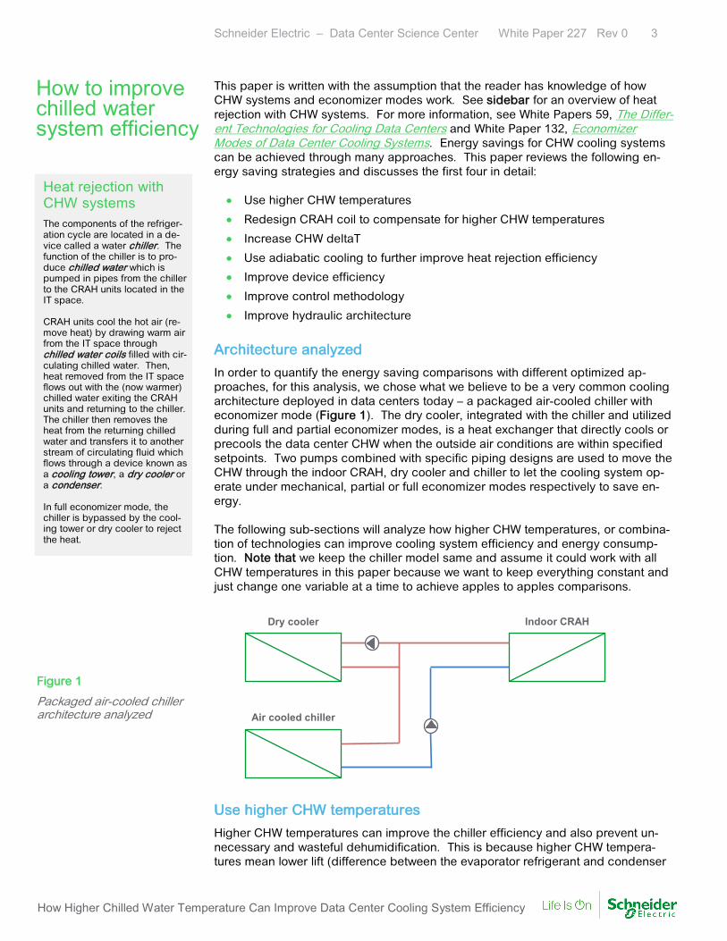
In order to quantify the energy saving comparisons with different optimized ap-proaches, for this analysis, we chose what we believe to be a very common cooling architecture deployed in data centers today – a packaged air-cooled chiller with economizer mode (Figure 1). The dry cooler, integrated with the chiller and utilized during full and partial economizer modes, is a heat exchanger that directly cools or precools the data center CHW when the outside air conditions are within specified setpoints. Two pumps combined with specific piping designs are used to move the CHW through the indoor CRAH, dry cooler and chiller to let the cooling system op-erate under mechanical, partial or full economizer modes respectively to save en-ergy. The following sub-sections will analyze how higher CHW temperatures, or combina-tion of technologies can improve cooling system efficiency and energy consump-tion. Note that we keep the chiller model same and assume it could work with all CHW temperatures in this paper because we want to keep everything constant and just change one variable at a time to achieve apples to apples comparisons.
Indoor CRAHDry cooler
Air cooled chiller
Use higher CHW temperatures
Higher CHW temperatures can improve the chiller efficiency and also prevent un-necessary and wasteful dehumidification. This is because higher CHW tempera-tures mean lower lift (difference between the evaporator refrigerant and condenser
How to improve chilled water system efficiency
Heat rejection with CHW systems The components of the refriger-ation cycle are located in a de-vice called a water chiller. The function of the chiller is to pro-duce chilled water which is pumped in pipes from the chiller to the CRAH units located in the IT space. CRAH units cool the hot air (re-move heat) by drawing warm air from the IT space through chilled water coils filled with cir-culating chilled water. Then, heat removed from the IT space flows out with the (now warmer) chilled water exiting the CRAH units and returning to the chiller. The chiller then removes the heat from the returning chilled water and transfers it to another stream of circulating fluid which flows through a device known as a cooling tower, a dry cooler or a condenser. In full economizer mode, the chiller is bypassed by the cool-ing tower or dry cooler to reject the heat.
Figure 1
Packaged air-cooled chiller architecture analyzed

Schneider Electric – Data Center Science Center White Paper 227 Rev 0 4
How Higher Chilled Water Temperature Can Improve Data Center Cooling System Efficiency
refrigerant pressure). In other words, the compressors don’t need to work so hard to reject heat energy. Meanwhile, the chillers can also operate in economizer mode for a larger portion of the year. However, the chillers must be capable of operating at higher water temperatures (see sidebar). Increasing CHW temperatures requires that we look at the entire cooling system ho-listically as the system dynamics are complex. Table 1 shows the impact of in-creasing CHW temperature in Frankfurt, Germany (see Appendix for more assump-tions). In the analysis for Table 1, we kept everything constant, including IT inlet air temperature fixed at 23°C (73.4°F), while increasing the CHW temperatures, which means the energy consumption of IT devices remains constant. The CRAH unit here is designed to work with a range of CHW temperatures which can provide roughly the same cooling capacity with the same power consumption when the CHW temperature is below about 13°C (55°F). When the CHW tempera-ture is increased above 13°C (55°F), the smaller delta T between the two fluids (air-flow and chilled water) reduces the cooling capacity of the CRAH unit. When the CHW temperature is increased to about 20°C (68°F) or above, we can’t achieve the same IT inlet air temperature with this CRAH unit and the CRAH coil must be rede-signed to compensate for higher CHW temperatures. The next sub-section will dis-cuss this behavior in detail. From Table 1, as the CHW temperature increases, we can conclude the following: • The chiller energy decreases due to improved chiller efficiency and increased
economizer hours. However, as the chilled water increases to 15°C (59°F) or above, more CRAH units must be added to provide enough cooling capacity and also to achieve the same IT inlet supply temperature. As more CRAH units are added, the CRAH fan speed is reduced to further reduce energy consumption. However, the CRAH capital cost increases.
• The chiller capacity increases with warmer CHW temperatures. Although we kept the same chiller size (for an apples to apples comparison), it’s possible to reduce the chiller size at higher CWH temperatures, thereby reducing the cooling system capital cost.
• The total cooling system energy decreases. These savings depend on many factors like data center location, cooling system configuration, etc.
Chilled Water Temp.
Chiller Max. Cap.
(kW)
Full / Partial Economizer
Hours
Total Chiller Energy (kWh)
CRAH Unit Capacity
& Quantity
Total CRAH Energy (kWh)
Total Cooling Energy (kWh)
Total Energy Savings
7°C (45°F) 903 246 / 3,650 2,349,926 200 kW (5) 353,028 3,051,602 Baseline
10°C (50°F) 1,002 1,451 / 3,706 2,001,754 200 kW (5) 353,028 2,703,430 11%
13°C (55°F) 1,109 2,324 / 3,530 1,676,653 200 kW (5) 353,028 2,378,329 22%
15°C (59°F) 1,184 3,236 / 3,377 1,468,820 166 kW (6) 325,872 2,143,340 30%
17°C (63°F) 1,261 3,896 / 3,393 1,279,330 125 kW (8) 226,358 1,854,337 39%
Operating tempera-tures of chillers Every chiller has a maximum chilled water temperature it is capable of supplying. This is limited by the type and design of the chiller. Depending on the chiller type, the chiller com-ponents may require special features which allow for higher chilled water supply tempera-tures. We recommend you consult with your chiller vendor before increasing your chilled water setpoints.
Table 1 Impact of chilled water temperature on cooling system (Frankfurt, Germany)

Schneider Electric – Data Center Science Center White Paper 227 Rev 0 5
How Higher Chilled Water Temperature Can Improve Data Center Cooling System Efficiency
Redesign CRAH coil to compensate for higher CHW temperatures
In this section, the CRAH coil is essentially “tuned” for a particular CHW system. For our analysis, the IT inlet air temperature is kept constant, which has the effect of decreasing the CRAH coil capacity as the CHW temperature increases. In the pre-vious subsection, we increased the number of CRAH units to compensate for this. However, the best approach is to redesign the CRAH coils to compensate for the higher CHW temperatures, although these CRAH coils will typically cost more. To illustrate the impact of the CRAH coil on the total cooling energy, we started with the analysis from Table 1, except that we replaced the original CRAH coil with the optimal CRAH coil for the two highest CHW temperatures. These results are shown in Table 2. Note that the CRAH coils for Table 1 are already designed and opti-mized for CHW temperatures below 13°C (55°F), therefore, the total CRAH energy for these chilled water temperatures are the same in Tables 1 and 2.
Chilled Water Temp.
Chiller Max. Cap.
(kW)
Full / Partial Economizer
Hours
Total Chiller Energy (kWh)
CRAH Unit Capacity
& Quantity
Total CRAH Energy (kWh)
Total Cooling Energy (kWh)
Total Energy Savings
7°C (45°F) 903 246 / 3,650 2,349,926 200 kW (5) 353,028 3,051,602 Baseline
10°C (50°F) 1,002 1,451 / 3,706 2,001,754 200 kW (5) 353,028 2,703,430 11%
13°C (55°F) 1,109 2,324 / 3,530 1,676,653 200 kW (5) 353,028 2,378,329 22%
15°C (59°F) 1,184 3,236 / 3,377 1,468,820 166 kW (6) 325,872 2,143,340 30%
17°C (63°F) 1,261 3,896 / 3,393 1,279,330 125 kW (8) 226,358 1,854,337 39%
20°C (68°F) 1,350 5,157 / 3,009 1,044,646 125 kW (8) 203,232 1,596,526 48%
21°C (70°F) 1,428 5,854 / 2,312 950,191 125 kW (8) 222,854 1,521,693 50%
With optimal CRAH coils, as the CHW temperature increases from 17°C (63°F) to 20°C (68°F), the CRAH energy is further reduced to achieve more energy savings. However, even with the optimized coil at 21°C (70°F) CHW temperature, the CRAH fan energy increases slightly. Despite this increase, the total cooling energy is the lowest because the energy savings from the chillers offset the CRAH energy in-crease. We could have added more CRAH units to achieve lower CRAH energy, but this increases CRAH capital cost. This tradeoff should be evaluated to deter-mine the optimal CRAH quantity. Increase CHW deltaT
The power consumption of chilled water pumps and the CRAH unit fans, is directly proportional to the cube of the motor speed (specifically the shaft speed). The mo-tor speed is proportional to the water (or air) mass flow rate, which means the power consumption is proportional to the cube of the mass flow rate. From the for-mula, cooling capacity (Q) in units of kW:
Q = Mass Flow Rate × DeltaT × Specific Heat of Fluid We see that the mass flow rate and deltaT are inversely related (specific heat of fluid is a constant for a specific fluid at a given temperature). For a given amount of
Table 2 Impact of CRAH coil on cooling system (Frankfurt, Germany)

Schneider Electric – Data Center Science Center White Paper 227 Rev 0 6
How Higher Chilled Water Temperature Can Improve Data Center Cooling System Efficiency
heat energy (Q) rejected, if we increase deltaT, the mass flow rate is reduced which reduces the energy consumption of the pump and the CRAH unit fans. Figure 2 shows the reduction in pump or fan energy (measured in % of rated power consumption) as the mass flow rate is reduced (or deltaT is increased). For exam-ple, reducing the mass flow rate from 100% to 80% in pump or fan speed results in an energy saving of 49%.
To illustrate the impact of CHW deltaT on cooling system energy, we start with the analysis from Table 2, except that we vary the CHW deltaT. We choose the 20°C (68°F) CHW setpoint scenario, and change the CHW deltaT from 5°C (9°F) to 7°C (13°F) and to 10°C (18°F) to assess the deltaT impact on cooling system energy. Note that the return chilled water temperature from the IT space equals the setpoint plus the deltaT. These results are shown in Table 3.
Chilled Water DeltaT
Chiller Max. Cap. (kW)
Full / Partial Economizer
Hours
Total Chiller Energy (kWh)
CRAH Unit Capacity
& Quantity
Total CRAH Energy (kWh)
Total Pump Energy (kWh)
Total Cooling Energy (kWh)
Total Energy Savings
5°C (9°F) 1,350 5,157 / 3,009 1,044,646 125 kW (8) 203,232 348,648 1,596,526 Baseline
7°C (13°F) 1,365 5,157 / 3,267 973,625 125 kW (8) 250,186 127,020 1,350,830 15%
10°C (18°F) 1,400 5,157 / 3,522 872,756 111 kW (9) 228,636 75,336 1,176,728 26%
From these results we can conclude the following: • As the CHW deltaT increases, a significant amount of the pump energy is
saved due to lower pump speed.
• The chiller energy decreases further due to improved chiller efficiency (de-pendent on the chiller type and system design) and increased economizer hours. Although the smaller chilled water mass flow rate reduces the effec-tiveness of the chillers, the increased chilled water return temperatures com-pensate for this reduction. Meanwhile, the increased chilled water return tem-peratures leads to more economizer hours.
100%
73%
51%
34%22%
0%
20%
40%
60%
80%
100%
120%
50% 60% 70% 80% 90% 100% 110%
% o
f rat
ed p
ower
con
sum
ptio
n
% of rated mass flow rate
Figure 2
Performance curve of pumps or fans (power vs. mass flow rate)
Table 3 Impact of chilled water deltaT on chiller efficiency and pump energy (Frankfurt, Germany)
Schneider Electric – Data Center Science Center White Paper 227 Rev 0 7
How Higher Chilled Water Temperature Can Improve Data Center Cooling System Efficiency
• The CRAH energy increases because the heat transfer effectiveness of the CRAH coil is reduced due to the lower chilled water flow rate. In order to pro-vide the same cooling capacity, the CRAH fans need to spin up which means more fan energy. However, in this case, in order to achieve constant IT inlet temperature, the proper design practice is to increase the number of CRAH units and lower the airflow per CRAH as shown in 10°C (18°F) delta T sce-nario.
• Compared to the baseline case, the total cooling energy is further reduced, although the increased CRAH energy offsets some portion of the chiller and pump energy savings.
Use adiabatic cooling to further improve heat rejection efficiency
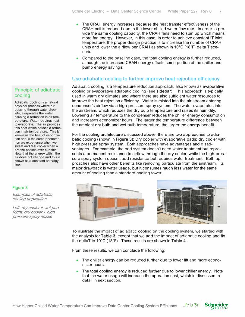
Adiabatic cooling is a temperature reduction approach, also known as evaporative cooling or evaporative adiabatic cooling (see sidebar). This approach is typically used in warm dry climates and where there are also sufficient water resources to improve the heat rejection efficiency. Water is misted into the air stream entering condenser’s airflow via a high-pressure spray system. The water evaporates into the airstream, which reduces the dry bulb temperature and raises its humidity. Lowering air temperature to the condenser reduces the chiller energy consumption and increases economizer hours. The larger the temperature difference between the ambient dry bulb and wet bulb temperature, the larger the energy benefit. For the cooling architecture discussed above, there are two approaches to adia-batic cooling (shown in Figure 3): Dry cooler with evaporative pads; dry cooler with high pressure spray system. Both approaches have advantages and disad-vantages. For example, the pad system doesn’t need water treatment but repre-sents a permanent resistance to airflow through the dry cooler, while the high-pres-sure spray system doesn’t add resistance but requires water treatment. Both ap-proaches also have other benefits like removing particulate from the airstream. Its major drawback is water usage, but it consumes much less water for the same amount of cooling than a standard cooling tower.
To illustrate the impact of adiabatic cooling on the cooling system, we started with the analysis for Table 3, except that we add the impact of adiabatic cooling and fix the deltaT to 10°C (18°F). These results are shown in Table 4. From these results, we can conclude the following: • The chiller energy can be reduced further due to lower lift and more econo-
mizer hours.
• The total cooling energy is reduced further due to lower chiller energy. Note that the water usage will increase the operation cost, which is discussed in detail in next section.
Principle of adiabatic cooling Adiabatic cooling is a natural physical process where air passing through water drop-lets, evaporates the water causing a reduction in air tem-perature. Water requires heat to evaporate. The air provides this heat which causes a reduc-tion in air temperature. This is known as the heat of vaporiza-tion and is the same phenome-non we experience when we sweat and feel cooler when a breeze passes over our skin. Note that the energy within the air does not change and this is known as a constant enthalpy line.
Figure 3
Examples of adiabatic cooling application Left: dry cooler + wet pad Right: dry cooler + high pressure spray nozzle

Schneider Electric – Data Center Science Center White Paper 227 Rev 0 8
How Higher Chilled Water Temperature Can Improve Data Center Cooling System Efficiency
Cooling System
Chiller Max. Cap. (kW)
Full / Partial Economizer
Hours
Total Chiller Energy (kWh)
CRAH Unit Capacity
& Quantity
Total CRAH Energy (kWh)
Total Pump Energy (kWh)
Total Cooling Energy (kWh)
Total Energy Savings
Without Adiabatic 1,400 5,157 / 3,522 872,756 111 kW (9) 228,636 75,336 1,176,728 Baseline
With Adiabatic 1,460 3,896 / 4,528 803,015 111 kW (9) 228,636 75,336 1,106,987 6%
Improve device efficiency
Another way of reducing cooling energy consumption is to choose cooling devices with higher efficiency. Improving device efficiency is an ongoing effort for cooling device manufactures. For example, adding variable frequency drive (VFD) to an existing chiller model, or designing a new chiller model with VFD, or designing a CRAH with variable speed fans. VFD matches the chiller motor speed to the cool-ing load which reduces the chiller power consumption, especially as the load on the compressor varies. For information on the characteristics of different types of com-pressors, see White Paper 254, The Different Types of Cooling Compressors. VFD can also be added to CHW pumps and CRAH unit fans to optimize the performance as the load varies (discussed in “Increase CHW deltaT” section). Improve control methodology
Cooling devices are normally controlled manually in a standalone and decentralized mode based on their return air temperature and humidity, or chilled water setpoints. For example, cooling devices like CRAHs/CRACs are adjusted manually by data center operators who change the setpoints, or turn the devices on based on their knowledge or intuition. These control practices lead to poor cooling system perfor-mance. The best practice is to adopt effective cooling control systems to reduce the energy consumption of the entire cooling system. For more information on this topic, see White Paper 225, Optimize Data Center Cooling with Effective Control Systems. Improve hydraulic architecture
By “hydraulic architecture” we mean the architecture of the CHW pumping system. The original intent of innovations in hydraulic architecture is to reduce the energy consumption of the pumps as the load varies. Since the pumps in the data center environment need to work all through the year, a variable speed pumping system is preferred in order to reduce the operation cost. An efficient pumping system allows chillers to operate at or close to its design del-taT over all expected load conditions while never allowing the flow rate to drop be-low the minimum to ensure chiller reliability (see sidebar). There are two typical hy-draulic architectures in data centers – primary variable speed pumping system and primary-secondary variable speed pumping system. A “primary-only pumping sys-tem” means that there is only one piping loop where the pumps change speed to reduce water flow rate under partial load conditions. Doing this can save pump en-ergy although the chiller efficiency is slightly reduced. A “primary-secondary pumping system” means that there are two piping loops. The water flow rate in the primary loop is constant to ensure the reliability and efficiency of the chiller. The secondary loop changes water flow rate to save pump energy while ensuring the cooling requirement during partial load conditions. Both approaches can save
Design principle of the chillers Chillers are normally optimized to operate with a specific chilled water deltaT (the temperature difference between supply and return chilled water). Chillers normally have a minimum allow-able chilled water flow rate re-quirement, which depends on the chiller type, to ensure the re-liability of the chillers. For partial load conditions, the water flow rate of the chillers must be reduced to achieve the specific water deltaT while keeping the flow rate above the minimum allowable range.
Table 4 Impact of adiabatic cooling on chiller efficiency (Frankfurt, Germany)

Schneider Electric – Data Center Science Center White Paper 227 Rev 0 9
How Higher Chilled Water Temperature Can Improve Data Center Cooling System Efficiency
pump energy through changing the speed or the quantity of running pumps. The selection between these two pumping systems are beyond the scope of this paper and is not discussed. The impact of raising CHW temperatures on total cost of ownership (TCO) can vary significantly depending on the cooling architecture and the climate. In this section, we modeled the packaged air-cooled chiller architecture described in this paper in two data center locations – Frankfurt, Germany and Miami, U.S. Figure 4 shows the variation in BIN data for these two locations to show how the distribution of temper-ature varies significantly. The number of hours at different temperature bins drives how many economizer hours you can gain when you raise the chilled water temper-ature. Meanwhile, it also drives how much water usage for adiabatic cooling. Based on the Köppen climate classification, we know that Frankfurt has a temperate oceanic climate and Miami has a tropical monsoon climate4. A data center with four cooling system variations are modeled – traditional with / without adiabatic cooling and optimized with / without adiabatic cooling (see Appendix for more assump-tions).
Temperature distribution (°F)
Miami
Frankfurt
Findings
Tables 5 and 6 summarize the energy consumption of a data center with the four cooling systems in two locations (Frankfurt and Miami respectively). From these re-sults, we can conclude the following: • Compared with the traditional CHW system, the optimized CHW system re-
duces energy consumption in Frankfurt by about 50% using the first four en-ergy saving strategies discussed in the “How to improve chilled water system efficiency” section (about 25% energy reduction in Miami).
4 https://en.wikipedia.org/wiki/K%C3%B6ppen_climate_classification “Tropical monsoon climates have
monthly mean temperatures above 18°C in every month of the year and feature wet and dry seasons.” “Temperate oceanic climates have the “coldest month averaging above 0°C (32°F), all months with av-erage temperatures below 22°C (71.6°F), and at least four months averaging above 10°C (50°F). No significant precipitation difference between seasons”.
Analysis of data centers with higher chilled water temperature
Figure 4
Variation in BIN data for two locations: Frankfurt and Miami (Vertical axis represents number of hours)

Schneider Electric – Data Center Science Center White Paper 227 Rev 0 10
How Higher Chilled Water Temperature Can Improve Data Center Cooling System Efficiency
• Adiabatic cooling improves these energy savings but to a lesser extent than the other energy-saving strategies. Adiabatic cooling resulted in more energy savings in Miami due to the warmer climate.
• Bin weather data is a significant driver in determining how much energy sav-ings can be achieved.
Cooling system
Chiller Max. Cap. (kW)
Full / Partial Economizer
Hours
Total Chiller Energy (kWh)
CRAH Unit Capacity &
Quantity
Total Pump Energy (kWh)
Total CRAH Energy (kWh)
Total Cooling Energy (kWh)
Total Energy Savings
Traditional without adiabatic 903 246 / 3,650 2,349,926 200 kW (5) 348,648 353,028 3,051,602 Baseline
Optimized without adiabatic 1,400 5,157 / 3,522 872,756 111 kW (9) 75,336 228,636 1,176,728 61%
Traditional with adiabatic 969 246 / 4,323 2,308,634 200 kW (5) 348,648 353,028 3,010,310 Baseline
Optimized with adiabatic 1,460 3,896 / 4,528 803,015 111 kW (9) 75,336 228,636 1,106,987 63%
Cooling system
Chiller Max. Cap. (kW)
Full / Partial Economizer
Hours
Total Chiller Energy (kWh)
CRAH Unit Capacity &
Quantity
Total Pump Energy (kWh)
Total CRAH Energy (kWh)
Total Cooling Energy (kWh)
Total Energy Savings
Traditional without adiabatic 909 0 / 53 3,645,814 200 kW (5) 348,648 353,028 4,347,490 Baseline
Optimized without adiabatic 1,410 126 / 7,166 2,584,876 111 kW (9) 56,414 228,636 2,869,926 34%
Traditional with adiabatic 963 0 / 53 3,479,614 200 kW (5) 348,648 353,028 4,181,290 Baseline
Optimized with adiabatic 1,470 288 / 7,004 2,277,616 111 kW (9) 56,414 228,636 2,562,666 39%
Tables 7 through 8 summarize the TCO of a data center with the different cooling system configurations in Frankfurt and Miami. Compared with the traditional chilled water system, the optimized system reduces cooling energy consumption by 64% in Frankfurt and 41% in Miami, with an increased cooling system capital cost of 13% for both. The 3-year TCO is reduced by 17% in Frankfurt and 12% in Miami. Note that the systems with adiabatic cooling require water, even in locations without suffi-cient water resource. The 13% capex premium shown in Tables 7 and 8 is at-tributed only to the special CRAH coil and adiabatic feature. However, in reality, you would use a lower cost chiller with 7°C water in a traditional design, which would mean that you would pay more than the 13% premium for the optimized chiller plant. Therefore, the total cost premium for the chiller plant when consid-ering a traditional chiller would be on the order of 15-20%.
Table 5 Cooling system energy comparison between traditional and optimized cooling system at 100% IT LOAD (Frankfurt)
Table 6 Cooling system energy comparison between traditional and optimized cooling system at 100% IT LOAD (Miami)

Schneider Electric – Data Center Science Center White Paper 227 Rev 0 11
How Higher Chilled Water Temperature Can Improve Data Center Cooling System Efficiency
Traditional
without adiabatic
Optimized with
adiabatic
Improvements over traditional
Total energy (kWh) 3,051,602 1,106,987 64%
pPUE (cooling only) 1.35 1.13 16%
Water usage (m3/year) 0 1,454 -
Capex $1,120,268 $1,265,507 13% increase
3-year TCO $1,810,812 $1,519,297 16%
Traditional
without adiabatic
Optimized with
adiabatic
Improvements over traditional
Total energy (kWh) 4,347,490 2,562,666 41%
pPUE (cooling only) 1.50 1.29 14%
Water usage (m3/year) 0 4,318 -
Capex $1,120,268 $1,126,507 13% increase
3-year TCO $2,104,057 $1,855,182 12%
Table 7 Improvements for Frankfurt comparing traditional and optimized cooling systems
Table 8 Improvements for Miami comparing traditional and optimized cooling systems

Schneider Electric – Data Center Science Center White Paper 227 Rev 0 12
How Higher Chilled Water Temperature Can Improve Data Center Cooling System Efficiency
Data center operators can achieve significant energy savings by increasing the CHW temperatures, CHW deltaT, and using adiabatic cooling for outdoor heat re-jection. These combined strategies can reduce energy consumption by 41% - 64%, which depends on the data center locations and cooling system configura-tions, while increasing the total cooling system capital cost by 15-20%.
However, keep the following in mind before adopting the strategies discussed in this paper:
• Ensure your chillers are capable of operating at higher CHW temperatureswithout impacting their reliability.
• Ensure the cooling capacity of indoor CRAH coils can provide your desired ITsupply setpoint at higher at higher CHW temperatures.
• Ensure that a source of low-cost water is available before using adiabaticcooling.
About the authorsPaul Lin is a Senior Research Analyst at Schneider Electric's Data Center Science Center.
He is responsible for data center design and operation research, and consults with clients on risk
assessment and design practices to optimize the availability and efficiency of their data center en-
vironment. Before joining Schneider Electric, Paul worked as the R&D Project Leader in LG Elec-
tronics for several years. He is now designated as a “Data Center Certified Associate”, an interna-
tionally recognized validation of the knowledge and skills required for a data center professional.
He is also a registered HVAC professional engineer. Paul holds a master’s degree in mechanical
engineering from Jilin University with a background in HVAC and Thermodynamic Engineering.
Victor Avelar is the Director and Senior Research Analyst at Schneider Electric’s Data Center Sci-
ence Center. He is responsible for data center design and operations research, and consults with
clients on risk assessment and design practices to optimize the availability and efficiency of their
data center environments. Victor holds a bachelor’s degree in mechanical engineering from Rens-
selaer Polytechnic Institute and an MBA from Babson College. He is a member of AFCOM.
John Bean Jr. is the Director of innovation for Racks and Cooling Solutions at Schneider Electric.
Previously John was World-Wide Engineering Manager for Cooling Solutions at Schneider Electric,
developing several new product platforms and establishing engineering and laboratory facilities in
both the USA and Denmark. Before joining APC, John was Engineering Manager for other compa-
nies involved in the development and manufacture of mission-critical cooling solutions.
Conclusion
RATE THIS PAPER

Schneider Electric – Data Center Science Center White Paper 227 Rev 0 13
How Higher Chilled Water Temperature Can Improve Data Center Cooling System Efficiency
The Unexpected Impact of Raising Data Center Temperatures White Paper 221
The Different Technologies for Cooling Data Centers White Paper 59
Economizer Modes of Data Center Cooling Systems White Paper 132
The Different Types of Cooling Compressors White Paper 254
Optimize Data Center Cooling with Effective Control Systems White Paper 225
Data Center Capital Cost Calculator TradeOff Tool 4
Cooling Economizer Mode PUE Calculator TradeOff Tool 11
Contact us For feedback and comments about the content of this white paper:
Data Center Science Center [email protected]
If you are a customer and have questions specific to your data center project:
Contact your Schneider Electric representative at www.apc.com/support/contact/index.cfm
Browse all white papers whitepapers.apc.com
tools.apc.com
Browse all TradeOff Tools™
Resources
© 20
17 S
chne
ider E
lectri
c. Al
l righ
ts re
serve
d.

Schneider Electric – Data Center Science Center White Paper 227 Rev 0 14
How Higher Chilled Water Temperature Can Improve Data Center Cooling System Efficiency
Assumptions for Table 1
• 1MW data center loaded to 100% to model worst case scenario
• IT inlet air temperature is fixed at 23°C (73.4°F).
• Chilled water deltaT (difference between the supply and return chilled water temperatures) is kept constant 5°C (9°F) as CHW temperature increases.
• Same CRAH unit coil (designed for CHW temperature from 7°C to 13°C) was used as CHW temperature increases.
• Chiller model is kept same in order to support all CHW temperatures thereby isolating the effect of CHW temperature.
• CRAH redundancy: N+1
• Chillers are in an N+1 configuration, sized for 20-year extreme temperature.
• Hot aisle containment is used.
• 20% glycol for the chilled water
• Chillers are without adiabatic cooling.
• Redundant CRAH units and chillers are standby.
• The energy consumption of the chilled water pump is fixed.
• Bin data from ASHRAE Weather Data Viewer 5.0 (2013) was used to calculate the chiller energy.
• Assume variable speed drive (VSD) pumps with constant performance are used which means same energy consumption of the pumps.
Assumptions for Table 7 to Table 8
• 1MW data center loaded to 100% to model worst case scenario
• IT inlet air temperature is fixed at 23°C (73.4°F).
• CRAH redundancy: N+1
• Chillers are in an N+1 configuration, sized for 20-year extreme temperature.
• Hot aisle containment is used.
• 20% glycol for the chilled water (only for Frankfurt and no need for Miami)
• Redundant CRAH units and chillers are in standby.
• Bin data from ASHRAE Weather Data Viewer 5.0 (2013) was used to calculate the chiller energy.
• The power train losses are not included in PUE.
• 3% cost of capital used for TCO calculations
• $0.08 per kilowatt hour cost of electricity and $0.8 per cubic meters ($3 per 1,000 gallons) cost of water
• The capital expense values were estimated using component, labor, and de-sign prices typically seen in a 1MW data center project. Most of this data came from the Data Center Capital Cost Calculator.
• For cooling systems without adiabatic cooling, the optimized chillers cost the same with the traditional chillers although their performance is enhanced.
• The capex savings of hydraulic system (i.e. piping, valves, etc.) are not con-sidered for larger CHW deltaT in these analysis.
Table A1 shows the detailed variable assumptions for the traditional and optimized cooling systems.
Appendix
T bl A1

Schneider Electric – Data Center Science Center White Paper 227 Rev 0 15
How Higher Chilled Water Temperature Can Improve Data Center Cooling System Efficiency
Cooling variable Traditional Optimized
IT inlet air temperature 23°C (73.4°F) 23°C (73.4°F)
CHW temperature 7°C (45°F) 20°C (68°F)
CRAH coil water temperature range 7°C (45°F) - 13°C (55°F) 20°C (68°F) or above
CHW deltaT 5°C (9°F) 10°C (18°F)
Chilled water pumps Constant speed Pumps with VSD
CRAH fans Fans with VSD Fans with VSD