hydraulic workshop crane silverline hwk kls · d gb f hydraulischer werkstattkran silverline...
TRANSCRIPT

F 09.02.136_PDF_28.03.2011 / UD
Hydraulischer Werkstattkran Hydraulic workshop crane Grue d’atelier hydraulique
SILVERLINE HWK KLS www.pfaff-silberblau.com
D Original Betriebsanleitung
GB Translated Operating Instructions
F Traduit Mode d’emploi Nr. 040025779_Ed.-04.2011

D GB F
Hydraulischer Werkstattkran SILVERLINE Hydraulic workshop crane SILVERLINE Grue d’atelier hydraulique SILVERLINE
F 09.02.136
technische Änderungen vorbehalten design changes under reserve changements techniques sous réserve 2 / 32
Tipp! Allgemeiner nützlicher Hinweis
Achtung! Wartungshinweise
Tip General, helpful tip
Important note! Maintenance information
Conseil ! Conseil d'utilité générale
Attention ! Consignes de maintenance
Vorsicht! Warnung vor einer allgemeinen Gefahr. Bei Missachtung Verlet-
Achtung! Schmierstoffentsorgung
Warning! Contains a warning that a general hazard exists. Risk of injury if warming
Important note! Disposal of lubricants
Prudence!
Signale un danger de type général. En cas de non-respect, risque de
Attention ! Elimination d'huiles usagées
Achtung! Wichtige Hinweise
Achtung! Entsorgung
Important note! Important information
Important note! Disposal
Attention! Remarques importantes
Attention ! Élimination
Achtung! Montage- und Einstellungshinweise
Important note! Assembly and adjustment information
Attention ! Consignes de montage et de réglage
D
Bestimmungsgemäße Verwendung .................................................................................... 4 Unfallverhütungsvorschriften............................................................................................... 4 Sicherheitshinweise............................................................................................................. 4 Technische Daten ............................................................................................................... 5 Inbetriebnahme ................................................................................................................... 5 Betrieb ............................................................................................................................. 7 Inspektions- und Wartungsanleitung ................................................................................... 8 Betriebsstörungen und ihre Ursachen................................................................................. 9
GB
Proper usage..................................................................................................................... 10 Accident prevention regulations ........................................................................................ 10 Safety instructions............................................................................................................. 10 Technical specifications .................................................................................................... 11 Using for the first time ....................................................................................................... 11 Operation .......................................................................................................................... 13 Inspection and servicing instructions................................................................................. 14 Malfunctions and their causes........................................................................................... 15
F
Utilisation conforme à l'affectation prévue......................................................................... 16 Prescriptions en matière de prévention des accidents ...................................................... 16 Consignes de sécurité....................................................................................................... 16 Caractéristiques techniques .............................................................................................. 17 Mise en service ................................................................................................................. 17 Mise en service ................................................................................................................. 19 Instructions d'inspection et de maintenance...................................................................... 20 Les dérangements et leurs causes ................................................................................... 21 Ersatzteilliste / Spare parts list / Liste des pièces détachées HWK KLS 0,5 ............. 22 Ersatzteilliste / Spare parts list / Liste des pièces détachées HWK KLS 1,0 ............. 26

D GB F
Hydraulischer Werkstattkran SILVERLINE Hydraulic workshop crane SILVERLINE Grue d’atelier hydraulique SILVERLINE
F 09.02.136
technische Änderungen vorbehalten design changes under reserve changements techniques sous réserve 3 / 32
E D
C B
M
G
K JI
A1A2
A3A4
F1.
..kg
F2.
..kg
F4.
..kg
F3.
..kg
H
K
H
I J
Type HWK KLS 0,5 HWK KLS 0,5 HWK KLS 1,0 HWK KLS 1,0
Art.-Nr. 040008514 040008515 040008516 040008517
Klappbar / Collapsible / Repliable „II“ „V“ „II“ „V“
F1 [kg] 500 500 1000 1000
F2 [kg] 400 400 800 800
F3 [kg] 350 350 700 700
F4 [kg] 250 250 500 500
A1 [mm] 1130 1130 1130 1130
A2 [mm] 1230 1230 1230 1230
A3 [mm] 1330 1330 1330 1330
A4 [mm] 1430 1430 1430 1430
B [mm] 2200 2200 2200 2200
C [mm] 2080 2080 2080 2080
D [mm] 940 940 940 940
E [mm] 770 770 770 770
G [mm] 1680 1680 1680 1680
H [mm] 1820 1820 1820 1820
I [mm] 850 850 850 850
J [mm] 990 990 990 990
K [mm] 620 620 620 620
M [mm] 160 160 160 160
„V“
„II“

Deutsch Hydraulischer Werkstattkran SILVERLINE F 09.02.136
technische Änderungen vorbehalten design changes under reserve changements techniques sous réserve 4 / 32
Vor Inbetriebnahme die Betriebsanleitung aufmerksam lesen! Sicherheitshinweise beachten! Dokument aufbewahren!
Bestimmungsgemäße Verwendung Der hydr. Werkstattkran ist eine Hebeeinrichtung zum manuellen Heben und Senken und Verfahren von Lasten. Er ist geeignet zur Verwendung auf ebenem, waagerechtem und befestigtem Boden. Maschineller Antrieb ist verboten. Nicht für Dauerbetrieb zugelassen Nicht geeignet für Einsatz in explosionsgefährdeten Räumen. Nicht geeignet für Einsatz in aggressiver Umgebung. Änderungen am Werkstattkran, sowie das Anbringen von Zusatzgeräten, sind nur mit unserer ausdrücklichen schriftlichen Genehmigung erlaubt. Technische Daten und Funktionsbeschreibung beachten!
Unfallverhütungsvorschriften Es sind jeweils die im Einsatzland gültigen Vorschriften zu beachten.1) in Deutschland z.Zt.: EG Richtlinie 2006/42/EG BGV D 8 Winden Hub- und Zuggeräte BGV D 6 Krane DIN EN 982 Hydraulische Komponenten DIN 15018-1 Krane - Stahltragwerk BGR 500 Kap. 2.8 Lastaufnahmeeinrichtungen im Hebezeugbetrieb 1) in der jeweils gültigen Fassung
Sicherheitshinweise Bedienung, Montage und Wartung nur durch: Beauftragtes, qualifiziertes Personal (Definition für Fachkräfte nach IEC 364)
Qualifiziertes Personal sind Personen, die aufgrund ihrer Ausbildung, Erfahrung, Unterweisung sowie Kenntnisse über einschlägige Normen und Bestimmungen, Unfallverhütungsvorschriften und Betriebsverhältnisse von den für die Sicherheit der Anlage Verantwortlichen berechtigt worden sind, die jeweils erforderliche Tätigkeit auszuführen und dabei mögliche Gefahren erkennen und vermeiden können.
Der Betrieb ist nur auf ebenem und befestigtem Boden zulässig. Das Befördern von Personen sowie der Aufenthalt im Gefahrenbereich ist verboten. Aufenthalt unter gehobener Last ist verboten. Nie in Bereiche bewegen, die nicht eingesehen werden können. Gesamter Hubbereich muss einschaubar sein. Nie in bewegliche Teile greifen. Mängel sind sofort sachkundig zu beheben. Lasten sind ausschließlich am Haken des Kranarmes zu befestigen. Last nur senkrecht heben. Schrägzug ist nicht erlaubt. Last nicht schwingen (schaukeln) lassen. Die Last nie in gehobenem Zustand unbeaufsichtigt schweben
lassen. Traglast nicht überschreiten (entspr. Traglastschildern). Kran darf nur manuell verfahren werden, die Benutzung von
zusätzlichen Transportmitteln ist verboten! Die Last möglichst niedrig, unter Beachtung der Bodenfreiheit
unter der Last, über den Flur transportieren Den Kran nie auf schiefen Ebenen benutzten. In Arbeitspausen bzw. in Parkposition den Werkstattkran mit
Feststellbremse gegen Lageveränderungen sichern! Vor Erstinbetriebnahme durch Sachkundigen prüfen.
-RICHTIG- -FALSCH-
Deutsch Hydraulischer Werkstattkran SILVERLINE F 09.02.136
technische Änderungen vorbehalten design changes under reserve changements techniques sous réserve 5 / 32
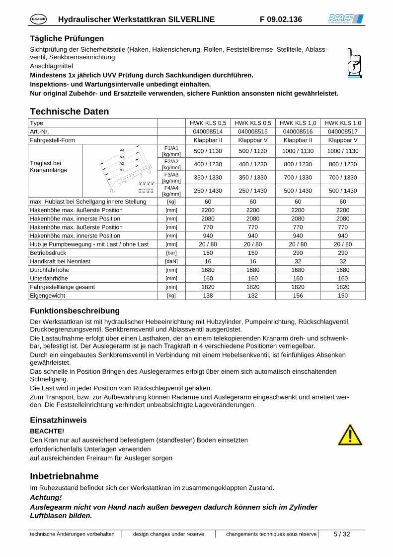
Tägliche Prüfungen Sichtprüfung der Sicherheitsteile (Haken, Hakensicherung, Rollen, Feststellbremse, Stellteile, Ablass-ventil, Senkbremseinrichtung. Anschlagmittel Mindestens 1x jährlich UVV Prüfung durch Sachkundigen durchführen. Inspektions- und Wartungsintervalle unbedingt einhalten. Nur original Zubehör- und Ersatzteile verwenden, sichere Funktion ansonsten nicht gewährleistet.
Technische Daten Type HWK KLS 0,5 HWK KLS 0,5 HWK KLS 1,0 HWK KLS 1,0
Art.-Nr. 040008514 040008515 040008516 040008517
Fahrgestell-Form Klappbar II Klappbar V Klappbar II Klappbar V F1/A1
[kg/mm] 500 / 1130 500 / 1130 1000 / 1130 1000 / 1130
F2/A2 [kg/mm]
400 / 1230 400 / 1230 800 / 1230 800 / 1230
F3/A3 [kg/mm]
350 / 1330 350 / 1330 700 / 1330 700 / 1330
Traglast bei Kranarmlänge
A1
A2
A3
A4
F1
...kg
F2
...kg
F3
...kg
F4
...kg
F4/A4
[kg/mm] 250 / 1430 250 / 1430 500 / 1430 500 / 1430
max. Hublast bei Schellgang innere Stellung [kg] 60 60 60 60
Hakenhöhe max. äußerste Position [mm] 2200 2200 2200 2200
Hakenhöhe max. innerste Position [mm] 2080 2080 2080 2080
Hakenhöhe max. äußerste Position [mm] 770 770 770 770
Hakenhöhe max. innerste Position [mm] 940 940 940 940
Hub je Pumpbewegung - mit Last / ohne Last [mm] 20 / 80 20 / 80 20 / 80 20 / 80
Betriebsdruck [bar] 150 150 290 290
Handkraft bei Nennlast [daN] 16 16 32 32
Durchfahrhöhe [mm] 1680 1680 1680 1680
Unterfahrhöhe [mm] 160 160 160 160
Fahrgestelllänge gesamt [mm] 1820 1820 1820 1820
Eigengewicht [kg] 138 132 156 150
Funktionsbeschreibung Der Werkstattkran ist mit hydraulischer Hebeeinrichtung mit Hubzylinder, Pumpeinrichtung, Rückschlagventil, Druckbegrenzungsventil, Senkbremsventil und Ablassventil ausgerüstet. Die Lastaufnahme erfolgt über einen Lasthaken, der an einem telekopierenden Kranarm dreh- und schwenk-bar, befestigt ist. Der Auslegerarm ist je nach Tragkraft in 4 verschiedene Positionen verriegelbar. Durch ein eingebautes Senkbremsventil in Verbindung mit einem Hebelsenkventil, ist feinfühliges Absenken gewährleistet. Das schnelle in Position Bringen des Auslegerarmes erfolgt über einem sich automatisch einschaltenden Schnellgang. Die Last wird in jeder Position vom Rückschlagventil gehalten. Zum Transport, bzw. zur Aufbewahrung können Radarme und Auslegerarm eingeschwenkt und arretiert wer-den. Die Feststelleinrichtung verhindert unbeabsichtigte Lageveränderungen.
Einsatzhinweis BEACHTE! Den Kran nur auf ausreichend befestigtem (standfesten) Boden einsetzten erforderlichenfalls Unterlagen verwenden auf ausreichenden Freiraum für Ausleger sorgen
Inbetriebnahme Im Ruhezustand befindet sich der Werkstattkran im zusammengeklappten Zustand.
Achtung! Auslegearm nicht von Hand nach außen bewegen dadurch können sich im Zylinder Luftblasen bilden.

Deutsch Hydraulischer Werkstattkran SILVERLINE F 09.02.136
technische Änderungen vorbehalten design changes under reserve changements techniques sous réserve 6 / 32
Betriebsbereitschaft herstellen: (nur auf ebenem, waagerechtem, befestigtem Boden verwenden)
Achtung! Entriegelte Radarme immer festhalten! Verletzungsgefahr
Transportein-stellung
Aufstellbügel einschwenken
1. Aufstellbügel entsichern (Sicherungssplint herauszie-hen) und in Funktionsposition (Pfeilrichtung) bringen
2. Bolzensicherung entfernen (Sicherungsfeder lösen) 3. Bolzen entriegeln
4. Fahrwerksholm ausklappen
(Auf Bewegungsfreiraum achten. Es dürfen sich keine Gegenstände im Bewegungsbereich be-finden. Der Bediener muss darauf achten, dass etwaige weitere Personen, ausreichend Abstand zum Kran achten!)
5. Fahrgestell durch Fußkraft etwas
anheben 6. Gelenkbolzen einstecken und sichern
7. Gelenkbolzen verriegeln und
sichern
8. Nach dem Verriegeln und Sichern des ersten Fahrwerkholmes den 2. Fahrwerkholm ausklappen, verriegeln und sichern.
9. Alle Verriegelungen und Si-cherungen auf ordnungsge-mäßen Sitz prüfen
10. Die Umstellung in den Trans-portzustand erfolgt in gleicher Weise in umgekehrter Reihen-folge.
ACHTUNG: Beim Verschieben des zusammengeklappten Kranes auf ebenem, glatten Boden achten. Beim Auftreten von Hindernissen (Unebenheiten im Boden) besteht Umstürzgefahr.
Handhabung
Prüfung vor Arbeitsbeginn:
einwandfreie Funktion der Stellteile Funktion der Feststelleinrichtung Zustand der Laufrollen und Rollenachsen Haken und Lastaufnahmemittel
Fahren und Lenken mittels Handgriff Der Kran ist zum Verfahren von Lasten nur für geringe Wege geeignet. Last möglichst niedrig über dem Boden verfahren. Beim Verfahren mit Last ist darauf zu achten, dass die Last nicht schwingt bzw. schaukelt. Den Kran nur mittels Handgriff verschieben, nie den Ablasshebel oder den Pumphebel dazu benutzten. Da der Kran nur eine Feststelleinrichtung besitzt, darf er nicht auf Steigungen und Gefällen eingesetzt werden. Währen des Hubvorgangs und beim Abstellen ist die Feststelleinrichtung zu betätigen.
Handgriff
Ablasshebel
Pumphebel
feststellen
lösen

Deutsch Hydraulischer Werkstattkran SILVERLINE F 09.02.136
technische Änderungen vorbehalten design changes under reserve changements techniques sous réserve 7 / 32
Pumphebel- Aufbewahrungsort
Aufnehmen der Last Auslegearm in gewünschte Hubstellung bringen und verriegeln Vergewissern sie sich, dass die Tragfähigkeit des Kranes in der jeweiligen Tragarmlänge nicht überschritten wird. Die jeweiligen Belastungsangaben (siehe unten) sind zu beachten.
1000kg
F = 1000kg
A1
F = 800kg
800kg
A2
F = 700kg
700kg
A3
F = 500kg
500kg
A4
F = 250kg
A4
250kg
F = 350kg
500kg
350kg
A3 F = 400kg
400kg
A2 F = 500kg
A1
Position Auslegearmes Der Ausleger kann in 4 verschiedene Arbeitsstellungen verwendet werden.
Kranarm verstellen:
Sicherungssplint und Bolzen herausziehen Kranarm in die gewünschte Position bringen Bolzen in die entsprechende Bohrung einstecken und sichern.
Inbetriebnahme erst nach Prüfung aller Bolzenverbindungen mit Sicherung
Betrieb Sicherstellen, dass die Sicherheitslasche des Kranhakens nach dem Einhängen des Hebehilfsmittels richtig geschlossen ist.
Heben Pumphebel in Pumphebelhalter einstecken Den Pumphebel abwechselnd auf und ab bewegen um
Öldruck im Zylinder aufzubauen (Pumphebelmechanismus ist mit Rückholfeder ausgestattet).
Bei Unterbrechung der Pumpbewegungen, bleibt der Kranarm in der er-reichten Position stehen.
Wird beim Heben der Anschlag des hydraulischen Zylinders erreicht, kommt das Druckbegrenzungsventil zum Ansprechen.
Sobald der Kran bis zum Anschlag angehoben ist, darf der Pumphebel nicht mehr betätigt werden.
Senken Senkhebel in Pfeilrichtung bewegen. Senkgeschwindigkeit der Last
anpassen. Beim Loslassen des Senkhebels wird die Senkbewegung unterbrochen. Die max. Senkgeschwindigkeit wird unabhängig von der Last durch ein
Senkbremsventil geregelt.
Handgriff
Senkhebel
Pumphebel

Deutsch Hydraulischer Werkstattkran SILVERLINE F 09.02.136
technische Änderungen vorbehalten design changes under reserve changements techniques sous réserve 8 / 32
Inspektions- und Wartungsanleitung Inspektionsintervalle Wartungs- und Inspektionsarbeiten
Sichtprüfung der Stellteile und Lastaufnahmemittel (Haken, Hakensicherung)
Funktion des Werkstattkran
Bolzenverbindungen/-Sicherungen
Räder, Handgriffe und Absenkvorrichtung reinigen
täglich bzw. vor jedem Einsatz
Ist Leckage vorhanden?
vierteljährlich Bolzenlagerung schmieren
Lastaufnahmemittel prüfen, reinigen, ölen
Bewegliche Teile reinigen und ölen
halbjährlich
Bei seltener Verwendung Hubkolben hochpumpen und wieder ganz einfahren.
Ölstand kontrollieren
Sämtliche Teile des Kranes auf Verschleiß prüfen und falls erf. defekte Teile auswechseln.
Typenschild auf Lesbarkeit prüfen
jährlich
Sachkundigenprüfung durchführen lassen 1)
alle 2 Jahre Ölwechsel durchführen
1) z.B. durch Pfaff-silberblau Kundendienst
Die Lebensdauer des Gerätes ist begrenzt, verschlissene Teile müssen rechtzei-tig erneuert werden.
Hydraulikanlage Die Hydraulikanlage besteht aus Zylinder-Pumpeinheit mit eingebautem Ablassventil, Sicherheitsventil, eingebautem Überdruck- und Rückschlagventil. Außer den gem. Wartungsanleitung vorgeschriebenen Prüfungen und dem vorgeschriebenem Ölwechsel bedarf die Hydraulikanlage kaum einer Wartung. Vor Beginn der Wartungs- und Instandsetzungsarbeiten an der Hydraulikpumpe, ist diese zu entlasten (drucklos zu machen). Hydraulikpumpe nicht ohne Öl betätigen! Beim Ölwechsel muss das Öl aus dem Öltank abgesaugt werden. Nach dem Ölwechsel bzw. nach Bedarf, muss das Hydrauliksystem entlüftet werden. Das Entlüften nur im unbelasteten Zustand ausführen. Ölfüllmenge beachten!
Entlüftungsvorgang Mehrmals Hydraulik im unbelasteten Zustand betätigen (Heben-Senken).
Hydraulikschaltplan
A) Pumpe B) Ölfilter C) Druckbegrenzungsventil D) Senkbremsventil E) Absenkventil F) Rückschlagventil H) Zylinder

Deutsch Hydraulischer Werkstattkran SILVERLINE F 09.02.136
technische Änderungen vorbehalten design changes under reserve changements techniques sous réserve 9 / 32
Hydrauliköl- und Schmierstoffempfehlung Für eine einwandfreie Funktion des Kranes, wird ein Hydrauliköl, bzw. werden Schmierstoffe aus untenstehender Tabelle empfohlen. Diese Spezialöle genügen den techn. Anforderungen hinsichtlich Viskosität ( Walkpenetration ) und Pourpoint am besten. Die Schmierstoffe sind für Umgebungstemperaturen - 10° bis + 40° C ausgelegt.
Marke empf. Druckflüssigkeit für Hydraulikanlage: Hydrauliköl HLP - DIN 51524 T2 - ISO VG 32
Ölmenge l
Optimol Hydo Öl 5045
Esso Nuto H 32
BP Energol HLP 32
Shell Tellus Öl 32
Aral Vitam GF 32
Mobil D.T.E. 25
DEA Astron HLP 32
Altschmierstoff ist entspr. den gesetzlichen Bestimmungen zu entsorgen!
Betriebsstörungen und ihre Ursachen
Hydraulische Anlage
Störungen Ursachen Beseitigung
Last zu schwer, Druckbegrenzungsventil ist wirksam.
Last verringern! Kran hebt Last nicht an (Pumpe arbeitet einwandfrei)
Ablassventil schließt nicht mehr oder Ven-tilsitz ist durch Verschmutzung undicht.
Reinigen bzw. austauschen! *
Druckbegrenzungsventil verstellt oder Ven-tilsitz verschmutzt.
Ventil einstellen oder reinigen! * Kran hebt bei fördernder Pumpe, mit oder ohne Last, langsam oder gar nicht. Hydraulikpumpe ist defekt.
Undichtigkeit im Hydrauliksystem.
Hydraulikpumpe reparieren oder austauschen! * Gehobene Last sinkt selb-
ständig ab. Ablassventil schließt nicht mehr oder Ven-tilsitz ist durch Ölverschmutzung undicht
Reinigen bzw. austauschen!
Die gehobene Last sinkt zu langsam ab.
Temperatur zu niedrig - Hydrauliköl zu zäh Wärmeren Raum aufsuchen!
Der Kranarm senkt zu schnell ab
Senkbremsventil verstellt oder defekt. Zylinder aus der Pumpeneinheit aus-bauen, das Ventil abnehmen und prüfen. Falls defekt austauschen
Beim Pumpen wird der Kran-arm angehoben aber senkt schnell wieder ab.
Zuwenig Öl im Ölbehälter. Öl nachfüllen
Pumphebel bewegt sich nicht Rückschlagventil verschmutzt oder defekt. Ventil reinigen bzw. austauschen *. Pumphöhe wird nicht erreicht Dichtungen der Pumpeneinheit beschädigt.
Zu wenig Öl im Ölbehälter. Die Pumpeneinheit ausbauen und die Dichtungen erneuern. * Öl nachfüllen
Der Kranarm bleibt nicht in der gewünschten Arbeitsstellung stehen und senkt wieder ab.
Zylinderdichtungen beschädigt. Senkventil verschmutzt oder defekt.
Dichtungen erneuern * Ventil reinigen, bzw. austauschen *.
* Nur durch autorisierte Werkstätte
Entsorgung:
Nach Außerbetriebnahme sind die Teile des Staplers entsprechend den gesetzlichen Bestimmungen der Wiederverwertung zuzuführen bzw. zu entsorgen!

English Hydraulic workshop crane SILVERLINE F 09.02.136
technische Änderungen vorbehalten design changes under reserve changements techniques sous réserve 10 / 32
Read the operating manual carefully before using the crane. Follow the safety instructions. Keep the document in a safe place.
Proper usage The hydraulic crane is a lifting device designed for the manual lifting, lowering and transportation of loads. It is suitable for use on level, horizontal and firm floor/ground surfaces. It must not be used as a mechanical drive unit. It is not suitable for permanent operation. It is not suitable for use in rooms where there is a potential risk of explosions. It is not suitable for use in aggressive atmospheres. The workshop crane must never be altered or auxiliary units added without our express written approval. Refer to the technical data and function description.
Accident prevention regulations Compliance with the regulations in force in the country of use is mandatory 1) In Germany, these are currently as follows: EC Machinery directive 2006/42/EC BGV D8 Winches, lifting and towing equipment BGV D6 Cranes DIN EN 982 Hydraulic components DIN 15018-1 Cranes; steel structures; verification and analyses BGR 500 section 2.8 Load handling equipment in lifting gear 1) The latest versions are applicable
Safety instructions Operation, installation, and servicing must be left strictly to: Instructed, trained personnel (Definition of trained personnel according to IEC 364)
Trained personnel are people who, because of their education, experience, instruction and knowledge of the relevant standards and regulations, accident prevention regulations and operating conditions, have been authorized by the persons responsible for the safety of the system to carry out the necessary work and can identify and avoid possible dangers as they do so.
Use is only permitted on a level and firm floor/ground surface. The crane must not be used to transport personnel nor may personnel be located in the danger area. Do not stand under a raised load. Never move in areas which are obscured from view. You must be able to see the entire lifting area. Never reach into moving parts. Defects are to be rectified immediately by trained personnel. Loads must be fastened only to the hook on the crane arm. Lift the load vertically only. Lifting at a slant is not permitted. Never swing (rock) the load. Never slew the load off the ground without supervision. Never exceeds the load capacity (see load capacity plates). The crane may only be moved manually. Its use with any addi-
tional means of transport is prohibited! As far as the floor/ground clearance beneath the load permits,
transport the load at as low a height as possible. Never use the crane on uneven surfaces. During all breaks in work and when the crane is parked, always
apply the parking brake to ensure that the crane cannot change position!
Before the crane is used for the first time, a competent expert must inspect it.
-RIGHT- -WRONG-

English Hydraulic workshop crane SILVERLINE F 09.02.136
technische Änderungen vorbehalten design changes under reserve changements techniques sous réserve 11 / 32
Daily inspections Visual inspection of all safety parts (hook, safety catch, castors, parking brake, operating elements, lowering valve, lowering brake device). Lifting tackle The crane must undergo an accident prevention regulations test by an expert at least once a year. Keep precisely to the inspection and servicing intervals. Use only genuine accessory and spare parts; otherwise, the crane may not function safely.
Technical specifications Type HWK KLS 0,5 HWK KLS 0,5 HWK KLS 1,0 HWK KLS 1,0
Art. No. 040008514 040008515 040008516 040008517
Type of undercarriage Collapsible II Collapsible V Collapsible II Collapsible V F1/A1
[kg/mm] 500 / 1130 500 / 1130 1000 / 1130 1000 / 1130
F2/A2 [kg/mm]
400 / 1230 400 / 1230 800 / 1230 800 / 1230
F3/A3 [kg/mm]
350 / 1330 350 / 1330 700 / 1330 700 / 1330
Load capacity for each crane arm length
A1
A2
A3
A4
F1.
..kg
F2.
..kg
F3.
..kg
F4.
..kg
F4/A4
[kg/mm] 250 / 1430 250 / 1430 500 / 1430 500 / 1430
Max. lifting capacity with overdrive at the inner position
[kg] 60 60 60 60
Hook height at max. outer position [mm] 2200 2200 2200 2200
Hook height at max. inner position [mm] 2080 2080 2080 2080
Hook height at max. outer position [mm] 770 770 770 770
Hook height at max. inner position [mm] 940 940 940 940
Lift per pump movement – with load / without load
[mm] 20 / 80 20 / 80 20 / 80 20 / 80
Operating pressure [bar] 150 150 290 290
Hand force for nominal load [daN] 16 16 32 32
Overhead clearance height [mm] 1680 1680 1680 1680
Underclearance height [mm] 160 160 160 160
Overall undercarriage length [mm] 1820 1820 1820 1820
Net weight [kg] 138 132 156 150
Function description The workshop crane is equipped with a hydraulic lifting device with lifting cylinder, pump unit, non-return valve, pressure control valve, lowering brake valve and lowering valve. The load is held by a lifting hook which is fastened to a rotatable and swivellable telescopic crane arm. The cantilever arm can be locked in four different positions, depending on the admissible load. A built-in lowering brake valve in combination with a lever lowering control valve permits the load to be lowered with sensitivity. The cantilever arm can be positioned quickly using the overdrive which actuates automatically. The load is held in every position by the non-return valve. For transportation or storage purposes the wheel arms and cantilever arm can be folded in and locked. The parking brake prevents the crane from moving position unintentionally.
Notes on use IMPORTANT! Only ever use the crane on a sufficiently firm (stable) floor/ground surface. Use underlay material if necessary. Make sure there is sufficient clearance for the cantilever arm.
Using for the first time When not in use the workshop crane is folded together.
Important Never move the cantilever out by hand as this may cause air bubbles to form in the cylinder.

English Hydraulic workshop crane SILVERLINE F 09.02.136
technische Änderungen vorbehalten design changes under reserve changements techniques sous réserve 12 / 32
Making ready for use: (only ever use on a flat, horizontal floor/ground surface)
Important! Always hold unlocked wheel arms tightly! Risk of injury
Transportation position
Swinging down the upright bar
1. Unlock the upright bar (pull out the locking pin ) and move to the function position (direction of arrow).
2. Remove the retaining pin (slacken the stop spring). 3. Unlock the pin .
4. Swing down the
undercarriage bar (Check that there is sufficient room to maneuver. There must be no objects in the maneuvering area. The operator must ensure that any other persons in the vicinity keep a safe distance from the crane!)
5. Lift the undercarriage slightly with your
foot. 6. Insert the hinge pin and fasten.
7. Lock and fasten the hinge pin.
8. Once the first undercarriage bar has been locked and fastened, swing down the second undercarriage bar and lock and fasten.
9. Check that all locks and fasteners are fixed tightly.
10. To return to the transportation state, follow the above instructions in reverse order.
CAUTION:
When it is folded together, only ever push the crane on a smooth and level floor/ground surface. Any obstacles (uneven floor) may cause it to tip over.
Handling
Inspections required before starting work:
Check that the operating elements are in proper working order Check that the parking brake is in proper working order Check the condition of the castors and the castor axles Check the hook and the load bearing mechanism
Carrying and steering with the handle The crane is only suitable for carrying loads over short distances. Carry the load at as low a height above the floor/ground as possible. When carrying the load it is imperative that the load is not permitted to swing or rock. Use only the handle to move the crane. Never use the lowering lever or the pump lever to do so. Since the crane only has a single parking brake it must never be used on slopes and gradients. The parking brake must always be on during lifting and setting down.
Handle
Lowering lever
Pump leverl
lock
re lease

English Hydraulic workshop crane SILVERLINE F 09.02.136
technische Änderungen vorbehalten design changes under reserve changements techniques sous réserve 13 / 32
Pump leverdepository
handle
Lowering lever
pump lever
Picking up the load Move the cantilever arm to the desired lifting position and lock. Check that the load capacity of the crane is not exceeded for the length of the arm. Never exceed the load capacity specifications given below.
1000kg
F = 1000kg
A1
F = 800kg
800kg
A2
F = 700kg
700kg
A3
F = 500kg
500kg
A4
F = 250kg
A4
250kg
F = 350kg
500kg
350kg
A3 F = 400kg
400kg
A2 F = 500kg
A1
Cantilever arm position The cantilever arm can be used in four different working positions.
Adjusting the cantilever arm:
Pull out the locking pin and pin . Move the crane arm to the desired position. Insert the pins in corresponding holes and fasten.
Never start using before you have checked the pin connections and their fasteners.
Operation Check that the safety lug for the lifting hook is properly closed when the lifting tackle has been attached.
Lifting Attach the pump lever to the pump lever holder. Move the pump lever up and down to build up oil
pressure in the cylinder, (the pump lever mechanism is equipped with a restoring spring).
If the pumping movement is interrupted, the crane arm stays in the position it has reached.
If the stop on the hydraulic cylinder is reached during
pumping, the pressure control valve will cut in. Once the crane has reached the stop, you must cease operating the pump lever.
Lowering Move the lowering lever in the direction of the arrow. Adjust the speed of lowering to the load. Releasing the lowering lever stops the lowering movement. A lowering brake valve independently of the load regulates the maximum lowering speed.

English Hydraulic workshop crane SILVERLINE F 09.02.136
technische Änderungen vorbehalten design changes under reserve changements techniques sous réserve 14 / 32
Inspection and servicing instructions Inspection intervals Servicing and inspection work
Visual inspection of the operating elements and lifting tackle (hook, safety catch).
Check that the workshop crane is in proper working order.
Pin connections/fasteners.
Clean wheels, handles and lowering device.
Daily or before use
Are there any leaks?
Quarterly Grease all stud bearings
Check, clean and oil the load handling equipment.
Clean and oil moving parts.
Every six month
If used infrequently, pump up the lifting pistons and move completely in again.
Check the oil level.
Check all parts of the crane for wear and replace any defective parts if necessary.
Check that the model plate is completely legible.
Every year
Have the annual test carried out by an expert 1)
Every 2 years Change the oil.
1) e.g. by Pfaff-silberblau after-sales service
The service life of your crane is limited. Worn parts must be renewed in good time.
Hydraulic system The hydraulic system is comprised of a cylinder pump unit with a built-in lowering valve, safety valve and built-in overpressure and non-return valve. Apart from the inspections required in accordance with the maintenance instructions and the stipulated oil change, the hydraulic system should require little maintenance. Before starting any maintenance or repair work on the hydraulic pump, always first make sure that it is not under load (make it unpressurized). Never use the hydraulic pump without oil! To change the oil, the oil must be suctioned out of the oil tank. After the oil has been changed it may be necessary, or whenever needed otherwise, to bleed the air from the hydraulic system. Only ever bleed air from the system when not under load. Check the oil level!
Bleeding the air Actuate the hydraulic system several times when not under load (lift and lower).
Hydraulic system circuit
A) Pump B) Oil filter C) Pressure control valve D) Lowering brake valve E) Lowering valve F) Non-return valve H) Cylinder

English Hydraulic workshop crane SILVERLINE F 09.02.136
technische Änderungen vorbehalten design changes under reserve changements techniques sous réserve 15 / 32
Oils and lubricants recommended for the hydraulic system For the trouble-free use of the crane it is recommended that you use one of the hydraulic system oils and lubricants listed in the table below. These special-purpose oils are the best available to meet technical requirements in terms of viscosity (worked penetration ) and pour point. The lubricants are suitable for ambient temperatures of - 10° to + 40° C.
Brand Recommended hydraulic fluid for hydraulic system: Hydraulic oil HLP - DIN 51524 T2 - ISO VG 32
Oil quantity l
Optimol Hydo Oil 5045
Esso Nuto H 32
BP Energol HLP 32
Shell Tellus Oil 32
Aral Vitam GF 32
Mobil D.T.E. 25
DEA Astron HLP 32
Dispose of used lubricants in accordance with statutory regulations.
Malfunctions and their causes
Hydraulic system
Malfunction Causes Elimination
The load is too heavy, the pressure control valve cuts in.
Reduce the load! The crane does not lift the load (pump is in perfect working order). The lowering valve does not close any
more or there is a leak in the valve face because of soiling.
Clean or replace! *
The pressure control valve is displaced or the valve face soiled.
Adjust or clean the valve! * The crane lifts only slowly or not at all, with or without load, with the pump working. The hydraulic pump is defective.
Leak in the hydraulic system.
Repair or replace the hydraulic pump! * A lifted load lowers again of its
own accord. The lowering valve does not close any more or there is a leak in the valve face because of contaminated oil.
Clean or replace!
The lifted load is lowered too slowly.
Temperature too low – hydraulic oil too thick.
Use in a warmer room/area!
The crane arm is lowered too fast.
The lowering brake valve is displaced or defective.
Take the cylinder out of the pump unit, remove the valve and check. Replace if defective.
The crane arm lifts when pumped but then quickly lowers again.
Insufficient oil in the oil tank. Top up with oil.
The pump lever does not move.
The non-return valve is either soiled or defective.
Clean or replace the valve.*
The pump height is not reached.
The seals on the pump unit are damaged. Insufficient oil in the oil tank.
Remove the pump unit and replace the seals.* Top up with oil.
The crane arm does not stay in the desired working position and lowers again.
The cylinder seals are damaged. The lowering valve is soiled or defective.
Replace the seals.* Clean or replace the valve.*
* By authorized workshop only.
Disposal: After placing permanently out of service, the crane parts must be disposed of or recycled in accordance with statutory requirements!

Français Grue d’atelier hydraulique SILVERLINE F 09.02.136
technische Änderungen vorbehalten design changes under reserve changements techniques sous réserve 16 / 32
Lire attentivement le mode d'emploi avant la mise en service ! Observer les consignes de sécurité ! Conserver soigneusement le document !
Utilisation conforme à l'affectation prévue La grue d’atelier hydraulique est un dispositif de levage servant à soulever, à abaisser et à déplacer des charges. Elle convient à une utilisation sur des sols plans, horizontaux et consolidés. Tout entraînement mécanique est interdit. Non homologué pour le fonctionnement permanent Ne convient pas à l'utilisation dans des locaux exposés aux explosions. Ne convient pas à l'utilisation dans un environnement agressif. Toute modification pratiquée sur la grue d’atelier hydraulique ainsi que tout montage d'appareils auxiliaires nécessitent impérativement notre autorisation écrite préalable. Veuillez observer les caractéristiques techniques et la description du fonctionnement !
Prescriptions en matière de prévention des accidents Il y a lieu de toujours observer les prescriptions en vigueur dans le pays où vous opérez.1) En Allemagne, ce sont actuellement les prescriptions et directives suivantes : Directive 2006/42/CE relative aux machines BGV D 8 Treuils et appareils de levage et de traction BGV D 6 Grues DIN EN 982 Composants hydrauliques DIN 15018-1 Grues – ouvrages porteurs métalliques BGR 500 chap. 2.8 Dispositifs d'élingage dans le cade de l’utilisation d’engins de levage 1) dans la version actuellement en vigueur
Consignes de sécurité Maniement, montage et entretien réservés exclusivement au : Personnel qualifié et dûment habilité (Définition du personnel qualifié selon la directive IEC 364)
On entend par personnel qualifié les personnes qui, en raison de leur formation, de leur expérience et des instructions dont elles ont bénéficié, ainsi que par leur connaissance des normes, directives, règlements de prévoyance contre les accidents et conditions de service concernés, ont été habilitées par le responsable de la sécurité de la machine à accomplir la tâche nécessaire et sont en mesure de reconnaître et d'éviter les dangers pouvant éventuellement survenir dans ce contexte.
L’exploitation est autorisée uniquement sur des sols plans et consolidés. Il est interdit de transporter des personnes avec les engins de levage ainsi que de se tenir dans la zone de
danger. Il est interdit de se placer sous des charges en suspension. Ne jamais déplacer la charge dans des zones difficiles à surveiller. L'ensemble de la zone de levage doit être bien visible. Ne jamais introduire la main dans des éléments mobiles. Il convient de remédier immédiatement de manière compétente à tout défaut constaté. Les charges doivent être fixées exclusivement au crochet du dispositif d’accrochage de la flèche. Soulever la charge à la verticale uniquement. Il est interdit de tirer obliquement la charge. Ne pas faire osciller (balancer) la charge. Ne jamais laisser une charge levée et en suspension sans surveillance. Ne pas dépasser la capacité de charge prescrite (indiquée sur les
plaquettes correspondantes). La grue doit uniquement être translatée manuellement ; l'utilisation de
moyens de transport supplémentaires est interdite ! Transporter la charge le plus basse possible au-dessus du sol, en te-
nant compte de la garde au sol sous la charge. Ne jamais utiliser la grue sur des terrains en pente.
-CORRECT- -FAUX-
Pendant les pauses de travail et dans la position de repos, bloquer la grue d’atelier au moyen du frein d’immobilisation pour empêcher tout déplacement intempestif !
Faire effectuer un contrôle par un expert avant la première mise en service.

Français Grue d’atelier hydraulique SILVERLINE F 09.02.136
technische Änderungen vorbehalten design changes under reserve changements techniques sous réserve 17 / 32
Contrôles quotidiens Contrôle visuel des pièces de sécurité (crochet, blocage des crochets, galets, frein d'immobilisation,
organes de commande, purgeur, dispositif de freinage de descente). Matériel d’élingage Faire effectuer régulièrement par des spécialistes, au moins une fois par an, une inspection conforme à la directive de prévention des accidents. Observer impérativement les intervalles d'inspection et de maintenance prescrits. Utiliser exclusivement des accessoires et des pièces de rechange d'origine ; dans le cas contraire, le fonctionnement fiable ne pourrait être garanti.
Caractéristiques techniques Type HWK KLS 0,5 HWK KLS 0,5 HWK KLS 1,0 HWK KLS 1,0 Réf. art. 040008514 040008515 040008516 040008517 Forme du châssis Repliable II Repliable V Repliable II Repliable V
F1/A1 [kg/mm] 500 / 1130 500 / 1130 1000 / 1130 1000 / 1130
F2/A2 [kg/mm] 400 / 1230 400 / 1230 800 / 1230 800 / 1230
F3/A3 [kg/mm] 350 / 1330 350 / 1330 700 / 1330 700 / 1330
Charge pour longueur de flèche
A1
A2
A3
A4
F1.
..kg
F2.
..kg
F3.
..kg
F4.
..kg
F4/A4
[kg/mm] 250 / 1430 250 / 1430 500 / 1430 500 / 1430
Charge de levage max. en avance rapide position interne
[kg] 60 60 60 60
Hauteur max. de crochet pos. ext. extrême [mm] 2200 2200 2200 2200 Hauteur max. de crochet pos. int. extrême [mm] 2080 2080 2080 2080 Hauteur max. de crochet pos. ext. extrême [mm] 770 770 770 770 Hauteur max. de crochet pos. int. extrême [mm] 940 940 940 940 Course par actionnement de pompage - avec charge / sans charge
[mm] 20 / 80 20 / 80 20 / 80 20 / 80
Pression de service [bar] 150 150 290 290 Force manuelle avec charge nominale [daN] 16 16 32 32 Hauteur de passage [mm] 1680 1680 1680 1680 Hauteur libre [mm] 160 160 160 160 Longueur totale du châssis [mm] 1820 1820 1820 1820 Poids propre [kg] 138 132 156 150
Description du fonctionnement La grue d’atelier est équipée d’un dispositif de levage hydraulique muni d'un vérin de levage, d'une pompe, d'une valve anti-retour, d'un limiteur de pression, d'une valve de freinage à l’abaissement et d'un purgeur. L’accrochage de la charge s’effectue par le biais d’un crochet fixé sur une flèche télescopique orientable et inclinable. Le bras-levier est verrouillable dans 4 positions différentes, en fonction de la capacité de charge souhaitée. La valve de freinage à l’abaissement intégrée associée à une vanne d’abaissement du levier, permet d’assurer une descente progressive sans à-coups. La mise en position expresse du bras-levier s’effectue au moyen d’un déplacement rapide s'enclenchant automatiquement. La charge est maintenue par la valve anti-retour dans toute position souhaitée. Les bras de roue et le bras-levier peuvent être pivotés et bloqués pour effectuer le transport ou le rangement de l'engin. Le dispositif de blocage empêche tout déplacement intempestif.
Remarque d’utilisation ATTENTION : Utiliser la grue uniquement sur un sol suffisamment ferme (stable) ! Si nécessaire, utiliser des semelles d’appui Veiller à observer un espace libre suffisant pour la potence
Mise en service Quand la grue d’atelier est dans l’état de repos, elle est repliée.
Attention ! Ne pas déplacer manuellement le bras-levier vers l’extérieur, car des bulles d’air risqueraient de se former dans le vérin.

Français Grue d’atelier hydraulique SILVERLINE F 09.02.136
technische Änderungen vorbehalten design changes under reserve changements techniques sous réserve 18 / 32
Etablir l'état de service : (utiliser uniquement sur des sols plans, horizontaux et consolidés)
Attention ! Toujours maintenir les bras de roue déverrouillés ! Risque de blessures !
Réglage pour le transport
Pivoter l'étrier de positionnement
1. Retirer le cran d’arrêt (retirer la goupille de blocage ) de l’étrier et amener ce dernier dans la position de fonctionnement (sens de la flèche)
2. Retirer le blocage de boulon (desserrer le ressort d’arrêt)
3. Déverrouiller le boulon
4. Déplier le longeron du
châssis (veiller à respecter un espace de manoeuvre suffisant. S’assurer qu’aucun objet ne se trouve dans la zone de manoeuvre. L’opérateur doit veiller à ce toute autre personne présente se tienne suffisamment à l'écart de la grue !)
5. Soulever légèrement le châssis à la force du
pied 6. Emboîter le boulon d’articulation et le bloquer
7. Verrouiller et bloquer
le boulon d’articulation
8. Après le verrouillage et le blocage du premier longeron, déplier, verrouiller et bloquer le 2e longeron.
9. Vérifier que tous les dispositifs de verrouillage et de blocage sont correctement en place
10. Pour préparer l'engin avant de le transporter, procéder de manière identique, dans l'ordre inverse des opérations.
ATTENTION : Pour déplacer la grue repliée, veiller à utiliser un sol plan et lisse. En présence d’obstacles (inégalités du sol), la grue risque de basculer.
Maniement
Vérifications à effectuer avant le début du service :
parfait fonctionnement des organes de commande fonctionnement du dispositif de blocage état des galets de roulement et des axes crochet et dispositifs porteurs de charge
Conduite et manoeuvre au moyen de la manette La grue convient au déplacement de charges uniquement sur des courts trajets. Déplacer la charge, si possible, au plus près du sol. Lors du déplacement de la charge, veiller à ce qu’elle ne se balance pas et n’oscille pas. Déplacer la grue uniquement au moyen de la manette ; ne jamais utiliser à cette fin le levier de descente ou le levier de pompage. Etant donné que la grue ne possède qu'un seul dispositif de blocage, son utilisation est à proscrire dans les montées et les descentes. Pendant l’opération de levage et lorsque la grue est à l’arrêt, actionner le dispositif de blocage.
Manette
Levier de descente
Levier de pompage
bloquer
desserrer

Français Grue d’atelier hydraulique SILVERLINE F 09.02.136
technische Änderungen vorbehalten design changes under reserve changements techniques sous réserve 19 / 32
Prise des charges Amener le bras de levage dans la position souhaitée et le verrouiller. S’assurer que la capacité de charge de la grue n’est pas dépassée pour la longueur d’avant-bec respective. Les spécifications respectives concernant les charges (voir ci-dessous) sont à respecter.
1000kg
F = 1000kg
A1
F = 800kg
800kg
A2
F = 700kg
700kg
A3
F = 500kg
500kg
A4
F = 250kg
A4
250kg
F = 350kg
500kg
350kg
A3 F = 400kg
400kg
A2 F = 500kg
A1
Position du bras de levage Le bras de levage peut être utilisé dans 4 positions de service différentes.
Ajuster la flèche de grue :
Enlever la goupille de sécurité et le boulon Amener la flèche de grue dans la position souhaitée Emboîter le boulon dans le perçage prévu à cet effet, puis le bloquer.
Mise en service uniquement après avoir vérifié si tous les assemblages boulonnés sont correctement bloqués
Mise en service S’assurer que l’éclisse de sécurité du crochet est fermée correctement après l'accrochage du dispositif auxiliaire de levage.
Levage Emboîter le levier de pompage dans le support prévu à cet
effet Déplacer en alternance le levier en avant et en arrière pour
établir la pression d'huile dans le vérin (le mécanisme du levier de pompage est équipé d’un ressort de rappel).
Interrompre l’actionnement de la pompe a pour effet d’immobiliser le bras de grue dans la position atteinte.
Si la butée du vérin hydraulique est atteinte lors du levage, la soupape de limitation de pression est déclenchée.
Dès que la grue a atteint la position de butée lors de la manœuvre de levage, il est interdit de continuer d’actionner le levier de pompage.
Abaissement
Déplacer le levier de descente dans le sens de la flèche. Adapter la vitesse d’abaissement en fonction de la charge.
Relâcher le levier de descente a pour effet d’interrompre le mouvement d'abaissement. La vitesse de descente maximum est réglée indépendamment de la charge, au moyen d’une valve de freinage à l’abaissement.
Dépôt du levier
Manette
Levier de descente
Levier de pom

Français Grue d’atelier hydraulique SILVERLINE F 09.02.136
technische Änderungen vorbehalten design changes under reserve changements techniques sous réserve 20 / 32
Instructions d'inspection et de maintenance Intervalles d'inspection Travaux d'inspection et de maintenance
Contrôle visuel des organes de commande et des dispositifs d’élingage (crochet, blocage de crochet)
Fonctionnement de la grue d’atelier
Assemblages/Blocages des boulons
Nettoyer les roues, manettes et le dispositif d’abaissement
quotidiens et avant chaque utilisation
Vérifier s'il existe des fuites
trimestriels Graisser toute les paliers de boulon
Vérifier, nettoyer, huiler les dispositifs porteurs de charge
Nettoyer et huiler les éléments mobiles
semestriels
Si le piston de levée est rarement utilisé, pomper pour le faire remonter, puis le faire redescendre entièrement.
Vérifier le niveau d'huile
Vérifier le niveau d'usure de tous les composants de la grue d’atelier et remplacer les pièces défectueuses si nécessaire
Vérifier si la plaque signalétique est bien lisible
annuels
Faire effectuer un contrôle par des experts 1)
tous les deux ans Faire une vidange de lubrifiant
1) par le SAV de Pfaff silberblau, par exemple
La durée de vie de l'appareil est limitée ; les pièces usagées devront être remplacées à temps.
Système hydraulique Le système hydraulique est constitué d'un ensemble vérin-pompe avec purgeur intégré, soupape de sûreté ainsi que avec soupape de surpression et de non-retour intégrée. Hormis les contrôles prescrits conformément à la notice de maintenance et la vidange prescrite, le système hydraulique nécessite très peu d'entretien. Avant de commencer les travaux d’entretien et de mise en état sur la pompe hydraulique, supprimer la pression (dépressuriser). Ne pas actionner la pompe hydraulique en l’absence de fluide ! En cas de vidange, aspirer le fluide contenu dans le réservoir. Une fois la vidange effectuée ainsi qu’en cas de besoin, il convient de purger le système hydraulique. Effectuer la purge uniquement hors charge. Observer la quantité d’huile de remplissage !
Opération de purge Actionner à plusieurs reprises le système hydraulique hors charge (Montée-Descente).
Schéma hydraulique
A) Pompe B) Filtre à huile C) Soupape de limitation de pression D) Valve de freinage à l’abaissement E) Valve de descente F) Soupape anti-retour H) Vérin

Français Grue d’atelier hydraulique SILVERLINE F 09.02.136
technische Änderungen vorbehalten design changes under reserve changements techniques sous réserve 21 / 32
Fluides hydrauliques / lubrifiants recommandés Pour assurer le parfait fonctionnement de la grue, nous recommandons d’utiliser un fluide hydraulique et des lubrifiants mentionnés dans le tableau ci-après. Ces huiles spéciales répondent aux exigences techniques relatives à la viscosité (pénétration par foulage) et au point d’écoulement. Les lubrifiants sont conçus pour des températures ambiantes comprises entre - 10° et +40°C.
Marque Fluide sous pression conseillé pour l’installation hydraulique :
fluide hydraulique HL-DIN 51524 T2 ISO VG 32 Quantité d'huile l
Optimol Hydo Öl 5045
Esso Nuto H 32
BP Energol HLP 32
Shell Tellus Öl 32
Aral Vitam GF 32
Mobil D.T.E. 25
DEA Astron HLP 32
Le lubrifiant usé devra être éliminé conformément aux dispositions légales !
Les dérangements et leurs causes
Système hydraulique Dérangements Causes Remède
La charge est trop lourde, la soupape de limitation de pression est activée.
Diminuer la charge ! La grue ne soulève pas la charge (la pompe fonctionne correctement)
Le purgeur ne ferme plus ou le siège de soupape n'est plus étanche à cause de l'encrassement.
Procéder au nettoyage ou le remplacer *
La soupape de limitation de pression est mal ajustée ou le siège de soupape est encrassé.
Régler la soupape ou la nettoyer ! * La grue soulève lentement ou pas du tout, avec charge ou à vide, la pompe fonctionnant correctement.
La pompe hydraulique est défectueuse.
Fuite dans le système hydraulique.
Réparer ou remplacer la pompe hydraulique ! * La charge levée s’abaisse
automatiquement. Le purgeur ne ferme plus ou le siège de soupape n'est plus étanche à cause de l'encrassement par le fluide.
Procéder au nettoyage ou le remplacer !
La charge levée s’abaisse trop lentement.
Température trop basse - fluide hydraulique trop visqueux
Travailler dans un local plus chaud !
La flèche de la grue s’abaisse trop rapidement
Valve de freinage à l’abaissement mal ajustée ou défectueuse
Démonter le vérin de l’ensemble-pompe, retirer et contrôler la valve. La remplacer si elle est défectueuse
Lors du pompage, la flèche est soulevée mais s'abaisse à nouveau rapidement.
Pas assez de fluide dans le réservoir. Rajouter du fluide
Le levier de pompage ne se déplace pas
Soupape anti-retour encrassée ou défectueuse.
Nettoyer la soupape ou la remplacer*.
La hauteur de refoulement n’est pas atteinte
Les joints de l’ensemble-pompe sont endommagés. Pas assez de fluide dans le réservoir.
Démonter l’ensemble-pompe et remplacer les joints. * Rajouter du fluide
La flèche de grue ne reste pas dans la position de service souhaitée et s’abaisse à nouveau.
Les joints du vérin sont endommagés. Valve de descente encrassée ou défectueuse.
Remplacer les joints * Nettoyer la soupape ou la remplacer*.
* Uniquement par des ateliers de réparation dûment habilités
Elimination :
Après la mise hors service, les composants de la grue devront être remis aux collectes de recyclage ou être éliminés, conformément aux dispositions légales en vigueur.

D GB F
Werkstattkran / Workshop crane / Grue d’atelier Type HWK KLS 0,5 Art. Nr. 040008514; 040008515; F 09.02.136
COLUMBUS McKINNON Engineered Products GmbH Am Silberpark 2-8 86438 Kissing/Germany
Telefon: +49 8233 2121-800 Telefax: +49 8233 2121-805 www.pfaff-silberblau.com
Edition 08.2005 22 / 32
Ersatzteilliste / Spare parts list / Liste des pièces détachées HWK KLS 0,5
Bildliche Darstellung unverbindlich! Bei Ersatzteilbestellungen „Prüf. Nr, Type und Baujahr“ angeben ! Graphic representation not binding! For spare parts orders please state “Prüf. Nr., type and year of manufacture”! Représentation graphique sans engagement! En cas de commande veuillez indiquer le "Prüf-nr." type et l'année de fabrication » !
Pos.
Stü
ck
un
it
Un
ité Benennung Nomenclature Spécification Abmessungen / dimensions Art.Nr./ Ref.no.
no. réf
A 1 Lasthaken vollst. load hook complete crochet porte charge complet No. 1, 2, 3, 4, 54 040008514100
B 2 Lenkrad vollst. steering wheel complete roue directrice complet No. 29 - 41 040008514200
C 2 Laufrad vollst. carrying wheel complete roue de roulement complet No. 38, 39, 52, 53 040008514300
D 2 Laufrad vollst. carrying wheel complete roue de roulement complet No. 43, 44, 45 040008514400
G 1 Set Betätigungshebel set lever handle Set levier de manœuvre No. 15,16,18,19,20,23, D39, D40, D41, D54
040008514700

D GB F
Werkstattkran / Workshop crane / Grue d’atelier Type HWK KLS 0,5 Art. Nr. 040008514; 040008515; F 09.02.136
COLUMBUS McKINNON Engineered Products GmbH Am Silberpark 2-8 86438 Kissing/Germany
Telefon: +49 8233 2121-800 Telefax: +49 8233 2121-805 www.pfaff-silberblau.com
Edition 08.2005 23 / 32
Pos. S
tück
un
it
Un
ité Benennung Nomenclature Spécification Abmessungen / dimensions Art.Nr./ Ref.no.
no. réf
1 6 Sicherungsring für Welle retaining ring for shaft circlip extérieur Ø18 A 2 2 Distanzring distance ring bague d´écartement Ø60xØ18x15 A 3 1 Bolzen bolt boulon Ø18x82 A 4 1 Lasthaken vollst. hook assembly crochet porte charge compl. A 5 1 Ausleger Schiebestück jib extern bras de levage périphérique 0400085140056 2 Sicherungsring für Wellen retaining ring for shaft circlip extérieur Ø18 7 1 Bolzen bolt boulon Ø14x82 0400085140078 1 Ausleger vollst. jib assembly bras de levage complet 0400085140089 3 Splint splint pin goupille fendue Ø3x88 10 1 Bolzen bolt boulon Ø16x160 04000851401011 3 Sicherheitsmutter safety nut écrou de sécurité M18 DIN 980 12 3 Scheibe washer rondelle Ø18 13 3 Sechskantschraube hexagon screw vis hexagonal M18x100 DIN 931 10.9 14 1 Kransäule column colonne 15 1 Kunststoff Kugel plastic ball boule plastifiée G 16 1 Betätigungshebel lever handle levier de manœuvre G 17 2 Griff handhold poignée 04000851401718 1 Bolzen bolt boulon G 19 1 Sechskantmutter hexagon nut écrou hexagonal M8 DIN 934 -8 G 20 1 Gewindebolzen stud bolt boulon fileté G 21 1 Hydraulikpumpe hydraulic pump pompe hydraulique 04000851402122 1 Bolzen bolt boulon 04000851402223 1 Bremsseil brake cable câble de frein G 24 1 Spannstift spring type straight pin goupille à ressort 4x20 DIN 1481 25 1 Welle shaft arbre Ø16x610 040008514025
26 3 Zylinderschraube mit Innensechskant
hexagon socket head cap screw
vis à tête cylindrique à six pans creux
M8x16 DIN 912
27 2 Exzenterring eccentric ring anneau excentrique 04000851402728 1 Pedal pedal pédale 04000851402829 2 Sechskantschraube hexagon screw vis hexagonal M10x25 DIN 931-8.8 B 30 2 Sechskantmutter hexagon nut écrou hexagonal M10 DIN 934 -8 B 31 4 Ringmutter lifting eye nut écrou à anneau M24 B 32 2 Drucklager bearing palier B 33 2 Dichtungsring gasket ring rondelle d´étanchéité B 34 2 Drucklager bearing palier B 35 2 Radgabel wheel fork fourchette B 36 2 Bremse brake frein B
37 2 Zylinderschraube mit Innensechskant
hexagon socket head cap screw
vis à tête cylindrique à six pans creux
M12 x80- DIN 912 B
38 4 Rillenkugellager deep groove ball bearing roulement rainuré á billes B, C 39 4 Laufrad wheel roue B, C 40 2 Distanzhülse bushing douille d´écartement Ø17xØ12x51 B 41 2 Sechskantmutter hexagon nut écrou hexagonal M12 DIN 934 -8 B 42 2 Bolzen mit Splint bolt with splint pin boulon avec goupille fendue 04000851404243 2 Gewindebolzen bolt boulon D 44 2 Laufrad wheel roue D 45 2 Splint split pin goupille fendue D 46 1 Fahrwerksholm links carriage arbor left châssis de transport à gauche Type 040008514 04000851404646 1 Fahrwerksholm links carriage arbor left châssis de transport à gauche Type 040008515 04000851504647 1 Fahrwerksholm rechts carriage arbor right châssis de transport à droite Type 040008514 04000851404747 1 Fahrwerksholm rechts carriage arbor right châssis de transport à droite Type 040008515 040008515047
48 1 Zylinderschraube mit Innensechskant
hexagon socket head cap screw
vis à tête cylindrique á six pans creux
M8x40 DIN 912 51
49 1 Sicherheitsmutter safety nut écrou de sécurité M8 DIN 980 51 50 2 Abdeckung covering couvercle 51 51 1 Aufstellbügel upright bar cran d’arrêt 04000851405152 2 Sicherungsring für Wellen retaining ring for shaft circlip extérieur 18x1 DIN 471 C 53 2 Bolzen bolt boulon C 54 2 Dichtung gasket rondelle A 55 2 Dichtung gasket rondelle 56 2 Feder spring ressort B

D GB F
Werkstattkran / Workshop crane / Grue d’atelier Type HWK KLS 0,5 Art. Nr. 040008514; 040008515; F 09.02.136
COLUMBUS McKINNON Engineered Products GmbH Am Silberpark 2-8 86438 Kissing/Germany
Telefon: +49 8233 2121-800 Telefax: +49 8233 2121-805 www.pfaff-silberblau.com
Edition 08.2005 24 / 32
D24D23D22
D21
D20
D19
D9D10
D11
D13
D13D14D15D16
D17
D18D26
D25
D31D32D33
D27
D28
D8D59D58
D60
D57
D56
D55
D54
D39
D40
D52
D30
D53
D40D52D51D50
D34
D35D36
D37D38D45
D29
D30
D39
D40
D41
D46 D47D48D49
D42 D43 D44 D39
D1
D2
D3D4
D5
D6D7
D61
Bildliche Darstellung unverbindlich! Bei Ersatzteilbestellungen „Prüf. Nr, Type und Baujahr“ angeben ! Graphic representation not binding! For spare parts orders please state “Prüf. Nr., type and year of manufacture”! Représentation graphique sans engagement! En cas de commande veuillez indiquer le "Prüf-nr." type et l'année de fabrication » !
Pos.
Stü
ck
un
it U
nite
Benennung Nomenclature Spécification Abmessungen / dimensions
Art.Nr./ Ref.no. / no. réf
E (1) Dichtungssatz sealing set jeu de joints 040008514500
F (1) Überdruckventil pressure-relief valve soupape de surpression 040008514600

D GB F
Werkstattkran / Workshop crane / Grue d’atelier Type HWK KLS 0,5 Art. Nr. 040008514; 040008515; F 09.02.136
COLUMBUS McKINNON Engineered Products GmbH Am Silberpark 2-8 86438 Kissing/Germany
Telefon: +49 8233 2121-800 Telefax: +49 8233 2121-805 www.pfaff-silberblau.com
Edition 08.2005 25 / 32
Pos. S
tück
u
nit
Un
ite
Benennung Nomenclature Spécification Abmessungen / dimensions
Art.Nr./ Ref.no. no. réf
D1 1 Hubkolben piston piston D2 2 O-Ring o-ring joint torique E D3 1 Führung guiding guidage D4 1 O-Ring-Führung o-ring guiding guidage pour joint torique D5 1 O-Ring o-ring joint torique E D6 1 Dichtscheibe tightening washer rondelle d´étanchéité D7 1 Sechskantmutter hexagon nut écrou hexagonal M20x1,5 DIN D8 1 Überwurfmutter cap nut écrou-raccord D9 1 Dichtungsring gasket ring rondelle d´étanchéité
D10 1 Pumpkolben piston piston 040008514110D11 1 O-Ring o-ring joint torique E D12 1 Kugel ball bille D13 1 O-Ring o-ring joint torique E D14 1 Verschlussschraube locking screw vis de fermeture D15 1 Dichtungsring gasket ring rondelle d´étanchéité E D16 1 Abstreifer dust seal stripper E D17 1 Pumpenzylinder pump cylinder cylindre de la pompe 040008514117 D18 1 O-Ring o-ring joint torique E D19 1 Rückholfeder retaining spring ressort de rappel D20 1 Ventilsitz valve seating siège de soupape D21 1 Spannstift spring type straight pin goupille á ressort D24 D22 1 Kappe cap capot D24 D23 1 Federführung spring guide guidage à ressort D24 D24 1 Rückholfeder (Set) retaining spring (Set) ressort de rappel 040008514124D25 1 Hülse sleeve douille D26 1 Hebelaufnahme lever retainer appui à levier D27 1 Pumphebel pump lever levier de pompe D28 1 Handgriff handle grip manette D29 1 Flügelschraube wing screw vis à oreilles M8x10
D30 2 Zylinderschraube mit Innensechskant
hexagon socket head cap screw
vis á tête cylindrique á six pans creux
M8x50 DIN 912
D31 1 Verschlussschraube locking screw vis de fermeture F D32 1 O-Ring o-ring joint torique F D33 1 Druckfeder spring ressort F D34 1 Ventilkegel valve cone cône de soupape F D35 1 Druckstück thrust piece membre de pression F D36 1 Ventilsitz valve seat soupape F D37 2 O-Ring o-ring joint torique E , F D38 1 Kugel Steel ball bille F D39 2 Sechskantmutter hexagon nut écrou hexagonal M8 DIN 934 -8 G D40 2 Scheibe washer rondelle A 8,4 DIN 125-St G D41 1 Sechskantschraube hexagon screw vis hexagonale M8x20 DIN 931 8.8 G D42 1 Bolzen bolt boulon D43 1 Hebelstück lever plate levier D44 1 Gewindestift set screw vis sans tête M8x30 DIN 913 D45 1 Gewindestift set screw vis sans tête M8x12 DIN 913 D46 1 Aufnahmekopf retainer logement D47 1 Druckfeder spring ressort F D48 1 Kegelstift taper pin Goupille conique F D49 2 O-Ring o-ring joint torique E , F D50 1 Dichtungsring gasket ring rondelle d´étanchéité E D51 1 Sechskantschraube hexagon screw vis hexagonal M16x12 DIN 931 8.8 D52 2 Sicherheitsmutter safety nut écrou de sécurité D53 1 Verstellhebel Variation lever levier de manœuvre D54 1 Sechskantschraube hexagon screw vis hexagonale M8x22 DIN 931 8.8 G D55 1 Dichtungsring gasket ring rondelle d´étanchéité E D56 1 Sechskantschraube hexagon screw vis hexagonale M8x16 DIN 931 8.8 D57 1 Zylinderrohr vollst. cylinder assembly cylindre compl. D58 1 O-Ring o-ring joint torique E D59 1 Abstreifer dust seal stripper E D60 1 Distanzhülse bushing douille d´écartement D61 1 Spannstift spring type straight pin goupille á ressort 5x20 DIN 1481

D GB F
Werkstattkran / Workshop crane / Grue d’atelier Type HWK KLS 1,0 Art. Nr. 040008516; 040008517; F 09.02.136
COLUMBUS McKINNON Engineered Products GmbH Am Silberpark 2-8 86438 Kissing/Germany
Telefon: +49 8233 2121-800 Telefax: +49 8233 2121-805 www.pfaff-silberblau.com
Edition 08.2005 26 / 32
Ersatzteilliste / Spare parts list / Liste des pièces détachées HWK KLS 1,0
Bildliche Darstellung unverbindlich! Bei Ersatzteilbestellungen „Prüf. Nr, Type und Baujahr“ angeben ! Graphic representation not binding! For spare parts orders please state “Prüf. Nr., type and year of manufacture”! Représentation graphique sans engagement! En cas de commande veuillez indiquer le "Prüf-nr." type et l'année de fabrication » !
Pos. S
tück
u
nit
Un
ité Benennung Nomenclature Spécification Abmessungen /
dimensions Art.Nr./ Ref.no.
no. réf
A 1 Lasthaken vollst. load hook complete crochet porte charge complet No. 1, 2, 3, 4, 54 040008514100
B 2 Lenkrad vollst. steering wheel complete roue directrice complet No. 29 - 41 040008514200
C 2 Laufrad vollst. carrying wheel complete roue de roulement complet No. 38, 39, 52, 53 040008514300
D 2 Laufrad vollst. carrying wheel complete roue de roulement complet No. 43, 44, 45 040008514400
G 1 Set Betätigungshebel set lever handle Set levier de manœuvre No. 15,16,18,19,20,23, D39, D40, D41, D54
040008514700

D GB F
Werkstattkran / Workshop crane / Grue d’atelier Type HWK KLS 1,0 Art. Nr. 040008516; 040008517; F 09.02.136
COLUMBUS McKINNON Engineered Products GmbH Am Silberpark 2-8 86438 Kissing/Germany
Telefon: +49 8233 2121-800 Telefax: +49 8233 2121-805 www.pfaff-silberblau.com
Edition 08.2005 27 / 32
Pos. S
tück
un
it
Un
ité Benennung Nomenclature Spécification Abmessungen / dimensions
Art.Nr./ Ref.no. / no. réf
1 6 Sicherungsring für Welle retaining ring for shaft circlip extérieur Ø18x1,2 DIN 471 A 031040766 2 2 Distanzring distance ring bague d´écartement Ø60xØ18x15 A 3 1 Bolzen bolt boulon Ø18x82 A 4 1 Lasthaken vollst. hook assembly crochet porte charge compl. A 5 1 Ausleger Schiebestück jib extern bras de levage périphérique 0400085160056 2 Sicherungsring für Wellen retaining ring for shaft circlip extérieur Ø14x1 DIN 471/1 A2B 031040782
7 1 Bolzen bolt boulon Ø14x82 040008514007
8 1 Ausleger vollst. jib assembly bras de levage complet 0400085160089 3 Splint splint pin goupille fendue Ø3,2x80 DIN 94-St
10 1 Bolzen bolt boulon Ø16x160 04000851401011 3 Sicherheitsmutter safety nut écrou de sécurité M18 DIN 982 12 3 Scheibe washer rondelle A19 DIN 125-St 13 3 Sechskantschraube hexagon screw vis hexagonal M18x100 DIN 931 10.9 14 1 Kransäule column colonne 15 1 Kunststoff Kugel plastic ball boule plastifiée G 16 1 Betätigungshebel lever handle levier de manœuvre G 17 2 Griff handhold poignée 04000851401718 1 Bolzen bolt boulon G 19 1 Sechskantmutter hexagon nut écrou hexagonal M8 DIN 934-6 A2B G 031014360 20 1 Gewindebolzen stud bolt boulon fileté G 21 1 Hydraulikpumpe hydraulic pump pompe hydraulique 04000851402122 1 Bolzen bolt boulon 04000851602223 1 Bremsseil brake cable câble de frein G 24 1 Spannstift spring type straight pin goupille à ressort 4x20 DIN 1481 F/St 031051081 25 1 Welle shaft arbre Ø16x610 040008514025
26 3 Zylinderschraube mit Innensechskant
hexagon socket head cap screw
vis à tête cylindrique à six pans creux
M8x16 DIN 9128.8 A2B 031011945
27 2 Exzenterring eccentric ring anneau excentrique 04000851402728 1 Pedal pedal pédale 04000851402829 2 Sechskantschraube hexagon screw vis hexagonal M10x25 DIN 933-8.8 B 031014398 30 2 Sechskantmutter hexagon nut écrou hexagonal M10 DIN 934-6 B 031014391 31 4 Ringmutter lifting eye nut écrou à anneau M24 B 32 2 Drucklager bearing palier B 33 2 Dichtungsring gasket ring rondelle d´étanchéité B 34 2 Drucklager bearing palier B 35 2 Radgabel wheel fork fourchette B 36 2 Bremse brake frein B
37 2 Zylinderschraube mit Innensechskant
hexagon socket head cap screw
vis à tête cylindrique à six pans creux
M12 x80 DIN 912 B
38 4 Rillenkugellager deep groove ball bearing roulement rainuré á billes B, C 39 4 Laufrad wheel roue B, C 40 2 Distanzhülse bushing douille d´écartement Ø17xØ12x51 B 41 2 Sechskantmutter hexagon nut écrou hexagonal M12 DIN 934-8 B 031015004 42 2 Bolzen mit Splint bolt with splint pin boulon avec goupille fendue 04000851404243 2 Gewindebolzen bolt boulon D 44 2 Laufrad wheel roue D 45 2 Splint split pin goupille fendue D 46 1 Fahrwerksholm links carriage arbor left châssis de transport à gauche Type 040008516 04000851604646 1 Fahrwerksholm links carriage arbor left châssis de transport à gauche Type 040008517 04000851704647 1 Fahrwerksholm rechts carriage arbor right châssis de transport à droite Type 040008516 04000851604747 1 Fahrwerksholm rechts carriage arbor right châssis de transport à droite Type 040008517 040008517047
48 1 Zylinderschraube mit Innensechskant
hexagon socket head cap screw
vis à tête cylindrique á six pans creux
M8x45 DIN 912-8.8 51 031015963
49 1 Sicherheitsmutter safety nut écrou de sécurité M8 DIN 982-8 A2B 51 03101058150 2 Abdeckung covering couvercle 51 51 1 Aufstellbügel upright bar cran d’arrêt 04000851405152 2 Sicherungsring für Wellen retaining ring for shaft circlip extérieur 18x,21 DIN 471/1 C 031040766 53 2 Bolzen bolt boulon C 54 2 Dichtung gasket rondelle A 55 2 Dichtung gasket rondelle 56 2 Feder spring ressort B

D GB F
Werkstattkran / Workshop crane / Grue d’atelier Type HWK KLS 1,0 Art. Nr. 040008516; 040008517; F 09.02.136
COLUMBUS McKINNON Engineered Products GmbH Am Silberpark 2-8 86438 Kissing/Germany
Telefon: +49 8233 2121-800 Telefax: +49 8233 2121-805 www.pfaff-silberblau.com
Edition 08.2005 28 / 32
D24D23D22
D21
D20
D19
D9D10
D11
D13
D13D14D15D16
D17
D18D26
D25
D31D32D33
D27
D28
D8D59D58
D60
D57
D56
D55
D54
D39
D40
D52
D30
D53
D40D52D51D50
D34
D35D36
D37D38D45
D29
D30
D39
D40
D41
D46 D47D48D49
D42 D43 D44 D39
D1
D2
D3D4
D5
D6D7
D61
Bildliche Darstellung unverbindlich! Bei Ersatzteilbestellungen „Prüf. Nr, Type und Baujahr“ angeben ! Graphic representation not binding! For spare parts orders please state “Prüf. Nr., type and year of manufacture”! Représentation graphique sans engagement! En cas de commande veuillez indiquer le "Prüf-nr." type et l'année de fabrication » !
Pos.
Stü
ck
un
it
Un
ite
Benennung Nomenclature Spécification Abmessungen / dimensions
Art.Nr./ Ref.no. / no. réf
E (1) Dichtungssatz sealing set jeu de joints 040008514500
F (1) Überdruckventil pressure-relief valve soupape de surpression 040008514600

D GB F
Werkstattkran / Workshop crane / Grue d’atelier Type HWK KLS 1,0 Art. Nr. 040008516; 040008517; F 09.02.136
COLUMBUS McKINNON Engineered Products GmbH Am Silberpark 2-8 86438 Kissing/Germany
Telefon: +49 8233 2121-800 Telefax: +49 8233 2121-805 www.pfaff-silberblau.com
Edition 08.2005 29 / 32
Pos. S
tück
un
it
Un
ite
Benennung Nomenclature Spécification Abmessungen / dimensions
Art.Nr./ Ref.no. / no. réf
D1 1 Hubkolben piston piston D2 2 O-Ring o-ring joint torique E D3 1 Führung guiding guidage D4 1 O-Ring-Führung o-ring guiding guidage pour joint torique D5 1 O-Ring o-ring joint torique E D6 1 Dichtscheibe tightening washer rondelle d´étanchéité D7 1 Sechskantmutter hexagon nut écrou hexagonal M20x1,5 DIN 439 D8 1 Überwurfmutter cap nut écrou-raccord D9 1 Dichtungsring gasket ring rondelle d´étanchéité
D10 1 Pumpkolben piston piston 040008514110 D11 1 O-Ring o-ring joint torique E D12 1 Kugel ball bille D13 1 O-Ring o-ring joint torique E D14 1 Verschlussschraube locking screw vis de fermeture D15 1 Dichtungsring gasket ring rondelle d´étanchéité E D16 1 Abstreifer dust seal stripper E D17 1 Pumpenzylinder pump cylinder cylindre de la pompe 040008514117 D18 1 O-Ring o-ring joint torique E D19 1 Rückholfeder retaining spring ressort de rappel D20 1 Ventilsitz valve seating siège de soupape D21 1 Spannstift spring type straight pin goupille á ressort D24 D22 1 Kappe cap capot D24 D23 1 Federführung spring guide guidage à ressort D24 D24 1 Rückholfeder retaining spring ressort de rappel 040008514124 D25 1 Hülse sleeve douille D26 1 Hebelaufnahme lever retainer appui à levier D27 1 Pumphebel pump lever levier de pompe D28 1 Handgriff handle grip manette D29 1 Flügelschraube wing screw vis à oreilles M8x10
D30 2 Zylinderschraube mit Innensechskant
hexagon socket head cap screw
vis á tête cylindrique á six pans creux
M8x50 DIN 912 031014271
D31 1 Verschlussschraube locking screw vis de fermeture F D32 1 O-Ring o-ring joint torique F D33 1 Druckfeder spring ressort F D34 1 Ventilkegel valve cone cône de soupape F D35 1 Druckstück thrust piece membre de pression F D36 1 Ventilsitz valve seat soupape F D37 2 O-Ring o-ring joint torique E , F D38 1 Kugel Steel ball bille F D39 2 Sechskantmutter hexagon nut écrou hexagonal M8 DIN 934-6 A2B G 031014360 D40 2 Scheibe washer rondelle B 8,4 DIN 125-St G 031013751 D41 1 Sechskantschraube hexagon screw vis hexagonale M8x20 DIN 933-8.8 A2B G 031014401 D42 1 Bolzen bolt boulon D43 1 Hebelstück lever plate levier D44 1 Gewindestift set screw vis sans tête M8x30 DIN 913-45H 031014322 D45 1 Gewindestift set screw vis sans tête M8x12 DIN 913-A2-70 031012747 D46 1 Aufnahmekopf retainer logement D47 1 Druckfeder spring ressort F D48 1 Kegelstift taper pin Goupille conique F D49 2 O-Ring o-ring joint torique E , F D50 1 Dichtungsring gasket ring rondelle d´étanchéité E D51 1 Sechskantschraube hexagon screw vis hexagonal M16x16 DIN 933-8.8 03114371 D52 2 Sicherheitsmutter safety nut écrou de sécurité D53 1 Verstellhebel Variation lever levier de manœuvre D54 1 Sechskantschraube hexagon screw vis hexagonale M8x22 DIN 931 8.8 G D55 1 Dichtungsring gasket ring rondelle d´étanchéité E D56 1 Sechskantschraube hexagon screw vis hexagonale M8x16 DIN 933-8.8 031013211 D57 1 Zylinderrohr vollst. cylinder assembly cylindre compl. D58 1 O-Ring o-ring joint torique E D59 1 Abstreifer dust seal stripper E D60 1 Distanzhülse bushing douille d´écartement D61 1 Spannstift spring type straight pin goupille á ressort 5x22 DIN 1481 F-St 031051148

COLUMBUS McKINNON Engineered Products GmbH Am Silberpark 2-8 86438 Kissing/Germany
Telefon: +49 8233 2121-800 Telefax: +49 8233 2121-805 www.pfaff-silberblau.com
EG-Konformitäts-erklärung
im Sinne der EG-Maschi-nenrichtlinie 2006/42/EG,
Anhang II, Nr. 1A
EC-Declaration of Conformity
as defined by EC Machinery Directive 2006/42/EC,
annex II, No. 1A
Déclaration "CE" de Conformité
conformément à la directive "CE" relative aux machines
2006/42/CE, Annexe II No. 1A
Hiermit erklären wir, dass Herewith we declare that the supplied model of
Nous déclarons que le modèle
Hydraulischer Werkstattkran SILVERLINE; klappbar
Hydraulic workshop crane SILVERLINE; collapsible
Grue d’atelier hydraulique SILVERLINE ; repliable
Type HWK KLS 0,5 HWK KLS 0,5 HWK KLS 1,0 HWK KLS 1,0
Art.-Nr. 040008514 040008515 040008516 040008517
zum Heben und Senken von Lasten
for lifting and lowering of loads pour lever et baisser des charges
mit allen einschlägigen Bestimmungen der EG Maschinenrichtlinie 2006/42/EG in Übereinstimmung ist
complies with the relevant provisions of the EC Machinery directive 2006/42/EC applying to it
est conforme à l’ensemble des dispositions selon la directive 2006/42/CE relative aux machines
Angewendete harmonisierte Normen, insbesondere:
Applied harmonised standards, in particular: Normes harmonisées utilisées, notamment
DIN EN ISO 12100-1; DIN EN ISO 12100-2; DIN EN 982; DIN 15018-1,
Angewendete nationale Normen und technische Spezifikationen, insbesondere:
Applied national technical standards and specifications, in particular:
Normes et spécifications techniques nationales qui ont été utilisées, notamment
BGV D8; ; BGV D6; BGR 500-2.8
Ort/Datum Kissing, 01.04.2011
ppa. Ulrich Hintermeier i.V. Konrad Ertl Der Unterzeichnende ist bevollmächtigt die technischen Unterlagen gem. Anhang VII A zusammenzustellen und der zuständigen Behörde auf Verlangen zu übermitteln.
The signing is authorised to put together the technical documents in accordance with appendix VII A and to transmit to the responsible authority on demand.
Le signant est habilité à rassembler les documents techniques selon l'annexe VII A et à les transmettre, sur demande, aux autorités compétentes.
Für Komplettierung, Montage und Inbetriebnahme gem. Betriebsanleitung zeichnet verantwortlich:
Ort: ................................................................. Datum: ..................................................................
Verantwortlicher: ............................................. Firma: ..................................................................

COLUMBUS McKINNON Engineered Products GmbH Am Silberpark 2-8 86438 Kissing/Germany
Telefon: +49 8233 2121-800 Telefax: +49 8233 2121-805 www.pfaff-silberblau.com
Prüfnachweise Inspection Certificate / Certificat d’inspection
Datum der Inbetriebnahme:
Date of commissioning / Date de la mise en sevice
Prüfung vor der ersten Inbetriebnahme:
Inspection prior to first commissioning Inspection avant la première mise en service
durch:
by / par Firmenstempel / company stamp / cachet d’entreprise
Sachverständiger / Competent person / expert Sachkundiger
Wiederkehrende Prüfungen Regular Inspections / Inspections régulières
Prüfdatum
Inspection Date
Date d’inspection
Befund Result / Résultat
Unterschrift des Sachkun-digen/Sachverständiger
Signature of a competent inspector
Signature de l’expert
Mängel behoben
Defects eliminated
am durch
on by
le par
Alle Standorte finden Sie auf / All locations can be found at
www.pfaff-silberblau.com
D
COLUMBUS McKINNON Engineered Products GmbH Am Silberpark 2-8 86438 Kissing GERMANY Telefon +49 8233 2121-0 Telefax +49 8233 2121-805 [email protected] www.cmco.eu/pfaff-silberblau
Händler: Merchant / commerçant Firmenstempel/stamp/cachet de la maison
Bei Inbetriebnahme Typenschilddaten eintragen:
Note name-plate data when taking into operation:
Inscrire les données sur la plaque du constructeur pendant l’utilisation :
Prüf.- Nr. Test no. No. de vérification Type Type Type Art. Nr. Art. No. Réf. de l’article Basismodell Base modell Modèle de base Geräte/Fabrik-Nr. Device / Serial number Numéro de série Baujahr Year of manufacture Année de construction Hublast Capacity Capacité