hyperdrive pro 3 solid chassis - hyperdrive racing.com 3 solid manual.pdfthe hyperdrive pro 3 solid...
TRANSCRIPT

Hyperdrive Pro 3 Solid Chassis
© 2007 Hyperdrive RacingPublished September 2006

Congratulations! You now own a state of the art 1/10 scale oval race car. The Hyperdrive Pro 3 Solid Chassis has gone through months of testing by our factory drivers to insure that you get a car that has maximum performance and adjustability built in. In purchasing this kit you have not only helped the hobby and sport of Oval pan car racing by supporting your local hobby shop but you have also bought the quality of a Hyperdrive Racing performance product.
How well your car performs is dependant upon the assembly of your car kit. Take your time and assemble your car as shown in this manual. This will give you a good starting point from which you can make adjustments dependant upon the track you are racing on.
The following items are required to complete your car:• Two channel Surface Radio• Electronic Speed Control• Batteries (4 cell)• 05 Electric Motor• Shock Oil• Tires• Body
Tools needed in the construction of your car:• Phillips Screwdriver• Hobby Knife• Allen Wrenches; 3/32, 1/16 & 0.050• Pliers or appropriate sized Nut Drivers/Sockets
Introduction
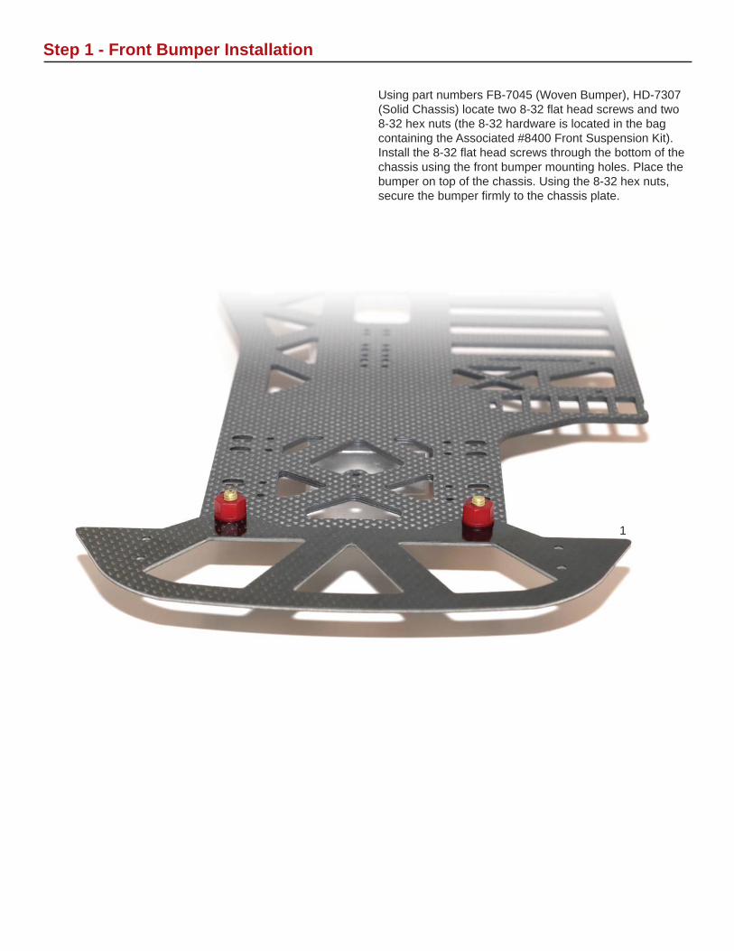
Using part numbers FB-7045 (Woven Bumper), HD-7307 (Solid Chassis) locate two 8-32 fl at head screws and two 8-32 hex nuts (the 8-32 hardware is located in the bag containing the Associated #8400 Front Suspension Kit). Install the 8-32 fl at head screws through the bottom of the chassis using the front bumper mounting holes. Place the bumper on top of the chassis. Using the 8-32 hex nuts, secure the bumper fi rmly to the chassis plate.
Step 1 - Front Bumper Installation
1
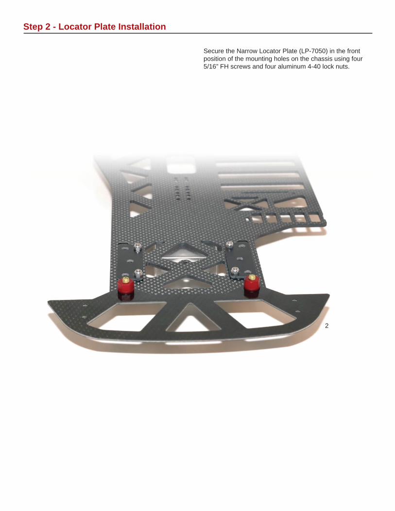
Secure the Narrow Locator Plate (LP-7050) in the front position of the mounting holes on the chassis using four 5/16” FH screws and four aluminum 4-40 lock nuts.
Step 2 - Locator Plate Installation
2
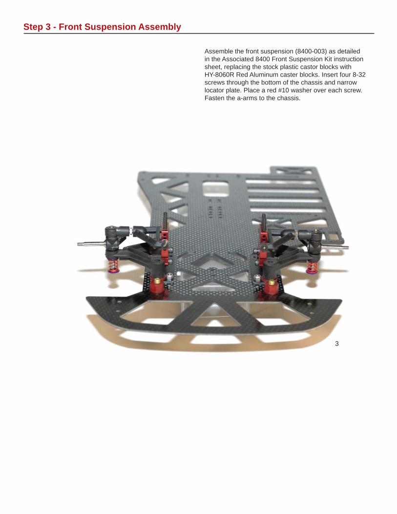
Assemble the front suspension (8400-003) as detailed in the Associated 8400 Front Suspension Kit instruction sheet, replacing the stock plastic castor blocks with HY-8060R Red Aluminum caster blocks. Insert four 8-32 screws through the bottom of the chassis and narrow locator plate. Place a red #10 washer over each screw. Fasten the a-arms to the chassis.
Step 3 - Front Suspension Assembly
3
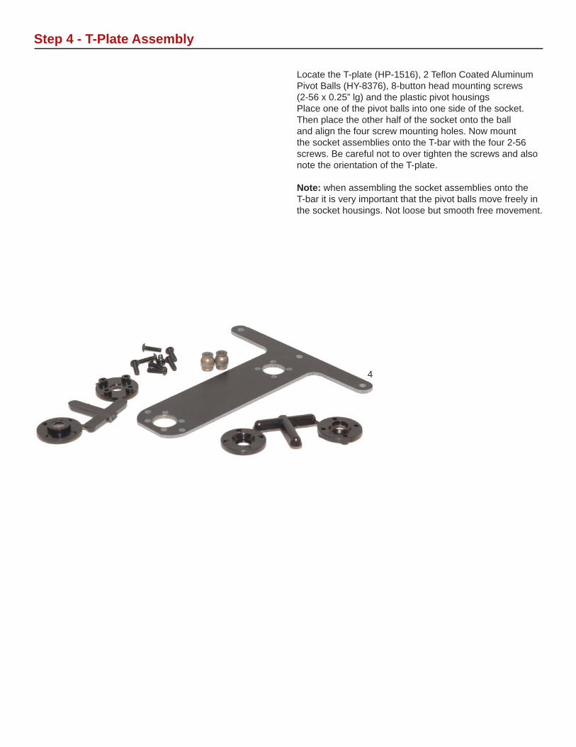
Locate the T-plate (HP-1516), 2 Tefl on Coated Aluminum Pivot Balls (HY-8376), 8-button head mounting screws (2-56 x 0.25” lg) and the plastic pivot housingsPlace one of the pivot balls into one side of the socket. Then place the other half of the socket onto the ball and align the four screw mounting holes. Now mount the socket assemblies onto the T-bar with the four 2-56 screws. Be careful not to over tighten the screws and also note the orientation of the T-plate.
Note: when assembling the socket assemblies onto the T-bar it is very important that the pivot balls move freely in the socket housings. Not loose but smooth free movement.
Step 4 - T-Plate Assembly
4

Locate the Bottom Plate (HD-7365), Right Side Pod Plate (HD-7340), Left Side Pod Plate (HD-7341), three .075 black t-plate spacers, four 1/4” FH screws, three 3/8” FH screws and 3 4-40 Aluminum lock nuts.
Insert the three 3/8” FH screws threw the bottom of the bottom plate using the right most set of holes. Next, place the .075 t-plate spacers over each screw. Place the t-plate over the screws and secure the t-plate with 3 4-40 locknuts as shown in fi gure 5. Finally, using the 1/4” FH screws, install both the right and left side pod plates to the bottom plate as shown in fi gure 5.
Step 5 - Rear Pod Assembly
5

Locate the Nerf Wing (HD-7303), two 5/16” FH screws, and two 4-40 aluminum lock nuts. Insert two 5/16” FH screws through the bottom of the chassis on the right hand side to mount the Nerf Wing. Place the nerf wing over the screws, and attach with two 4-40 locknuts.
Step 6 - Nerf Wing Installation
6

Using the rear pod from step 5, insert one 1/2” FH screw through the bottom of the chassis. Place the front t-plate pivot ball over the screw, and secure with a 4-40 lock nut. Refer to fi gure 7 for proper placement.
Step 7 - Pod Installation
7Slider Chassis Pictured
8
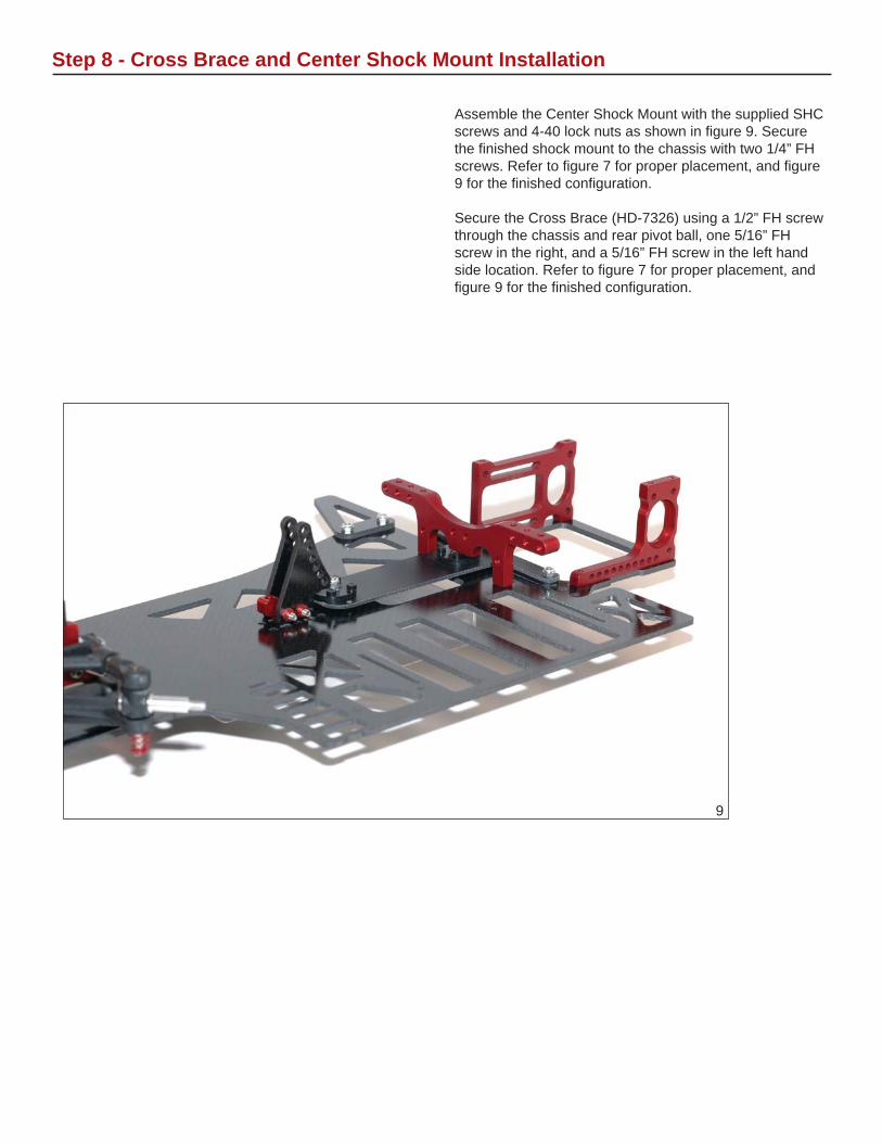
Assemble the Center Shock Mount with the supplied SHC screws and 4-40 lock nuts as shown in fi gure 9. Secure the fi nished shock mount to the chassis with two 1/4” FH screws. Refer to fi gure 7 for proper placement, and fi gure 9 for the fi nished confi guration.
Secure the Cross Brace (HD-7326) using a 1/2” FH screw through the chassis and rear pivot ball, one 5/16” FH screw in the right, and a 5/16” FH screw in the left hand side location. Refer to fi gure 7 for proper placement, and fi gure 9 for the fi nished confi guration.
Step 8 - Cross Brace and Center Shock Mount Installation
9

Locate the Shock & Body mounts (HD-7320), 2 Aluminum Ball studs, 8 1/4” BH screws, 4 .020 shims, and 2 4-40 lock nuts.
Install a ball stud from the front of the shock mount using the second hole down from the top. Place two .020” shims over the threaded shank of both ball studs. Secure them using a 4-40 lock nut. Repeat for the opposite side. Using two 1/4” BH screws each, attach the completed shock mount to the cross brace. Refer to fi gure 10 for proper placement.
Using the remaining four 1/4” BH screws, attach the body mounts to the cross brace.
Step 9 - Body & Side Shock Mount Installation
10
11

Locate the Center/Offset top plate (HD-7315), four 1/4” BH screws, three aluminum ball studs, and three 4-40 lock nuts. From the top of the top plate, insert one ball stud in the right most forward hole and secure it with a 4-40 lock nut from the bottom of the plate. Insert two more ball studs in the right most hole locations securing each with a 4-40 lock nut. Install the fi nished top plate onto the rear pod using the remaining four 1/4” BH screws. Refer to fi gure 12 as needed.
Step 10 - Top Plate Installation
12

Assemble the Center shock (TAM-1000R) and the side shocks (SK-1000R) as per the instructions included with each shock. Hyperdrive suggests using high quality silicon shock oils in your shocks. A good starting point on the shock setup is 40 wt. in the center shock and 30 wt. in both side shocks. Also start with the softer of the provided springs. At this time also attach the side shocks onto the ball ends. Make sure to use the included Associated Heavy Duty Ball Cups on both ends of the side shocks to attain proper shock length. The center shock will require a SHC screw and 4-40 lock nut supplied with the center shock mount for installation.
Step 11 - Shock Assembly and Installation
13

Locate the Ride Height Set (PP-2312) and choose the two adjusters with the holes in the center. Depending on the Final ride height of your car these may have to be changed. Note: Always install the same adjuster on each side of the pod in the same orientation. Failure to do this will cause the rear axle to bind and possibly destroy your bearings.
Insert the two adjusters into the Pod sides. Press them in until they are fl ush with the inside of the Pod sides. Install a Rear Axle / Right Hub Bearing (1/4” x 3/8” fl anged) into each of the Ride Height Adjusters (see fi gure 14).
Step 12 - Bearing Carrier Installation
14

Locate the following for the Diff and Rear Axle assembly: Rear Axle (RA-0401), Offset Diff Hub (RA-2405R), Left Side Wheel Hub (RA-2410R), Micro-Washers (RA-0403), Spur Gear Bearing (RA-0408-NF), Rear Axle and Right Hub Bearings (RA-0408), Diff Centering Set (RA-0411R), Diff balls (DB-0901), Diff Rings (DR-1002) and Spur Gear (SG-0116).
Install the Spur Gear Bearing (1/4” x 3x8” fl angeless) into the center of the Spur Gear. At this time also install the Diff Balls into the outer ring of holes in the Spur Gear. Install two of the Rear Axle / Right Hub Bearings (1/4” x 3/8” fl anged) into the Diff Hub. Place one of the Diff rings onto the shoulder of the axle.
Place a small amount of diff lube on each of the diff balls installed in the spur gear and place the spur gear assembly onto the axle. Now place the second diff ring onto the spur gear and slide the Diff Hub down over the axle making sure the diff ring aligns onto the shoulder of the hub.
Install the Diff Centering cone over the end of the axle and secure it with the supplied nylon nut. Tighten just enough to hold the assembly fi rmly together.
Step 13 - Rear Axle / Differential Assembly
15

Place three micro washers over the free end of the axle. Insert through the right bearing carrier. Place one more micro washer, and two wide axle spacers, and the left side clamping hub on the free end of the axle and tighten assembly.
Step 14 - Axle Installation
16
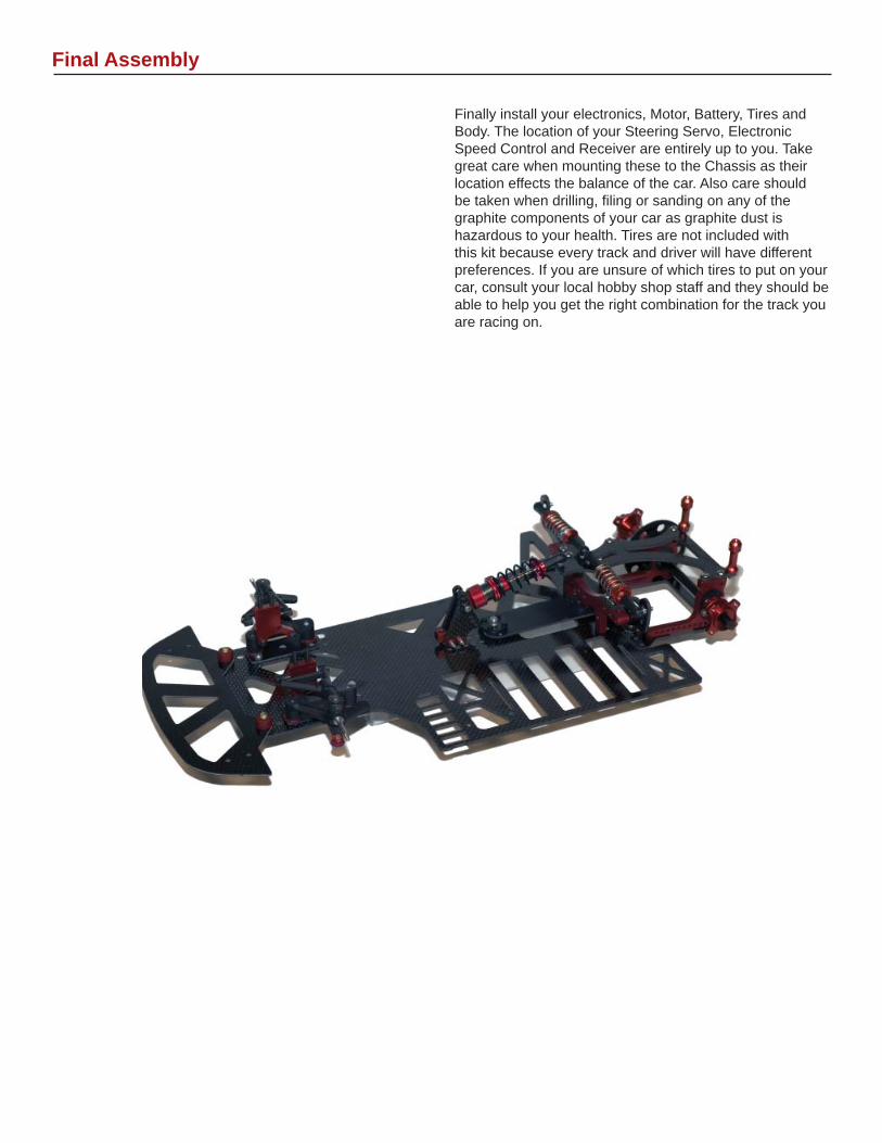
Finally install your electronics, Motor, Battery, Tires and Body. The location of your Steering Servo, Electronic Speed Control and Receiver are entirely up to you. Take great care when mounting these to the Chassis as their location effects the balance of the car. Also care should be taken when drilling, fi ling or sanding on any of the graphite components of your car as graphite dust is hazardous to your health. Tires are not included with this kit because every track and driver will have different preferences. If you are unsure of which tires to put on your car, consult your local hobby shop staff and they should be able to help you get the right combination for the track you are racing on.
Final Assembly