i a i c i nst - americanradiohistory.com a i r i c r i nst ct r voi. ... of engineering technology...
TRANSCRIPT

THE
i A i r
i C r
i NST CT r VoI. 25 No. 6 JANUARY 1972
TRANSISTOR TESTER Provides accurate measurements of transistor a.c. gain by means of a bridge technique, dispensing with the necessity for
an expensive meter. Also gives a measure of leakage current and checks
semiconductor diodes.
20p
IN T S I.C. INTRUDER ALARM www.americanradiohistory.com

Each £3 unit of Home Unit Insurance gives you protection up to the limit shown This is the simplified insurance you have been waiting for. Not just cover on the contents of your home but a
package of personal protection you and your family need. And it's how we save you so much money: just ONE policy to issue instead of nine! You can build up to the cover you need by additional units
(or # units after the first) up to a maximum of five. So simple. So easy. Apply to your Broker, Agent or local office of a General Accident company. The Home Unit Policy can replace your existing insurances And remember- as you buy more possessions just add more Home Units at any time.
THE GENERAL ACCIDENT FIRE & LIFE ASSURANCE CORPORATION LTD
Metropolitan House, 35 Victoria Avenue, Southend -on -Sea, Essex, SS2 6BT
It pays to be protected bya
Please send me further particulars of the Home Unit Insurance.
Name
Address
5304
www.americanradiohistory.com

REVERBERATION UNIT KIT 6 transistor reverberation chamber to which microphones, irstruments, etc., may be con- nected for added dimensional effect. The out- put is suitable for most amplifiers and the unit is especially suitable for use with elec- tronic organs. A ready -built spring and trans- ducer assembly used. Complete easy -:o -build kit, with constructional E7.50. Pre -drilled and printed case E1.70 extra. All parts available separately.
notes and circuits
WAH -WAH PEDAL KIT The Wilsic Wah -Wah pedal comprises a
SELECTIVE AMPLIFIER MODULE KIT, containing all the components to build a
two transistor circuit module, which may be used by the constructor for his own design or fitted to the FOOT VOLUME CONTROL PEDAL (as photo) converting
it :o Wah -Wah operation. This pedal is in strong fawn plastic and fitted with output lead and screened plug. Selective amplifier module kit E1.75. Foot Volume control pedal E5.13. COMPLETE KIT L6.50. Add 38p for assembly of module.
WILSIC VIBRATO UNIT A new kit to build a self -contained vibrato foot sw tch unit. 4- silicon transistor circuit in tough grey hammered finish metal cabinet. Variable speed and depth controls and on off foot switch. Ideal for guitars but unsuitable for high level inputs. COMPLETE KIT E5.2S, all parts available separately.
THE WILSIC BOOK OF CIRCUITS contains the full instructions for the Reverb unit, Wah -Wah pedal and our Vibrato unit.
PRICE ONLY 15p
SEND 5p in stamps for latest catalogue (Autumn 1971) of Hi -Fi, components, guitars, etc., etc. Friendly, high -speed service.
WILSIC ELECTRONICS LTD. 6 COPLEY ROAD, DONCASTER, YORKS
COMPONENTS HOBBYIST AMATEUR DOMESTIC
SURPLUS INDUSTRIAL BULK OFFERS
SELECTED PACKS 50p plus lop Post /Pack
21 4 x 4 pole, 3 way, wafer switch. 22 20 x equipment phono plugs, metal. 23 4 x 5k log pots. 24 20 x pvc clip on mes bulb holder. 25 3 pair Bulgin 5mm switched jack socket and
plug. 26 2 x 12volt solenoid and plunger. 27 4 x 3 pole, 7 way, wafer switch. 28 5 x 10k wirewound pots. 29 10 x 1 k 1 Owatt wirewound resistor. 30 15 x 15k 2%,1 watt resistor. 31 15 x 150k, 2 %, 2 watt resistor. 32 4 x 5k switched volume controls. 33 10 x 400 ohm, 10 watt wirewound resistors. 34 25 x 3.3pf 500v ceramic condenser. 35 10 x 330k, 1 %, 2 watt resistors. 36 4 x 2 pole, 5 way, wafer switch. 37 5 x 50k wirewound pots. 38 15 x 500pf 5% condensers. 39 25 x 220k, 3 watt resistors. 40 150 pieces paxoline, 4áx 2 x 8 ".
THE RADIO SHACK 9AM -8PM
161 ST. JOHN'S HILL
BATTERSEA, S.W.11 01 -223 5016
JANUARY 1972
Howoo A FAST EASY WAY TO LEARN BASIC
RADIO & ELECTRONICS Build as you learn with the exciting new TECHNATRON Outfit! No mathe- matics. No soldering -you learn the practical way.
Learn basic Radio and Electronics at home - the fast, modern way. Give yourself essential technical `know - how' - like reading circuits, assembling standard com- ponents, experimenting, building - quickly and without effort, and enjoy every moment. B.1.E.T.'s Simplified Study Method and the remarkable TECENATRON Self - Build Outfit take the mystery out of the subject, making learning easy and interesting.
Even if you don't know the first thing about Radio now,
you'll build your own Radio set within a month or so! and what's snore, you
will understand exactly what you are doing. The TECHNA- TRON Outfit contains every- thing you need, from tools to transistors even a versatile Multimeter which we teach you to use. All you need give is a little of your spare time and the surprisingly low fee, pay- able monthly if you wish. And the equipment remains yours, so you can use it again and again. You LEARN but it's as fascinating as a hobby. Among many other interesting experiments, the Radio set you build and it's a good one is really a bonus. This is first and last a teaching course, but the training is as fascinating as any hobby and it could be the springboard for a career in Radio and Electronics.
FREE BRITISH INSTITUTE
OF ENGINEERING
TECHNOLOGY
A I4- year -old could understand and benefit from this Course but it teaches the real thing. The easy to understand, practical projects from a burglar -alarm to a sophisticated Radio set help you traster basic Radio and Electronics even if you are a `non- techn..cal' type. And, if you want to make it a career, B.I.E.T. has a fine range of Courses up to City and Guilds standards. New Specialist Booklet If you wish to make a career in Electronics, send for your FREE copy of `OPPORTUNITIES IN TELECOMMUNICATIONS I TV AND RADIO'. This brand new booklet just out tells you all about TECHNATRON and B.1.E.T.'s full range of courses.
Dept. B9, ALDERMASTON COURT, READING RG7 4PF
Accredited by the Council for the Accreditation of Correspondence Colleges.
POST THIS COUPON FOR FREE BOOK
rPlease send books and full infirmation - free and without obligation.
I
I
I
I
NAME AGE (BLOCK CAPITALS PLEASE)
ADDRESS
OCCUPATION
I
I
I
I To B.I.E.T. Dept. B9, Aldermaston Court, Reading RG7 4PF
L N - n - n 321
www.americanradiohistory.com

NEW LOW PRICE TESTED S.C.R.'S. 30A
TO -48 £p
1.15 1.40 1.60 1.75 - 4.00
PIV IA 3A 7A 10A 16A TO -5 TO -66 10-66 TO -48
Lp £p £p Lp £p 50 0.23 0.25 0.47 0.50 0.53
100 0.25 0.33 0.53 0.58 0.63 200 0.35 0.37 0.57 0.61 0.75 400 0.43 0.47 0.67 0.75 0.93 600 0.53 0.57 0.77 0.97 1.25 800 0.63 0.70 0.90 1.20 1.50
SILICON RECTIFIERS -TESTED PIV 300(äA 750mA
£p £p IA £p
1.5A Lp
3A Lp
IOA Lp
50 0.04 0.05 0.05 0.07 0.14 0.21 100 0.04 0.06 0.05 0.13 0.16 0.23 200 0.05 0.09 0.06 0.14 0.20 0.24 400 0.06 0.13 0.07 0.20 0.27 0.37 600 0.07 0.16 0.10 0.23 0.34 0.45 800 0.10 0.17 0.13 0.25 0.37 0.55
1000 0.11 0.25 0.15 0.30 0.46 0.63 1200 - 0.33 - 0.33 0.57 0.75
TRIACS
VBOM 2A 6A 10A
TO-1 TO-66 TO-88
£p £p £p
100 0.30 0.50 0.75
200 0.50 0.60 0.90
400 0.70 0.75 1.10
30A £p
0.47 0.75 1.00 1.25 1 85 2.00 2.60
LUCAS SILICON RECTIFIERS
35 -Amp, 400 P.I.V., Stud Type £1.10 each.
DIACS FOR USE WITH TRIACS BR100 (D32) 37p each
2A POTTED BRIDGE RECTIFIERS 200V SOp
UNIJUNCTION UT46. Eqvt. 2N2646, Eqvt. TIS43. BEN3000 27p each. 25-99 26p 100 UP 20p.
NPN SILICON PLANAR BC107/8/9, 10p each: 50-99, 9p; 100 up, 8p each; 1,000 off, 7p each. Fully tested and coded TO -18 case.
BRAND NEW TEXAS GERM. TRANSISTORS
Coded and Guaranteed Pak No. EQVT TI 2G371B 0071 T2 D1374 0075 T3 D1216 OC81D T4 2G381T OC81 T5 2G382T 0082 TO 2G344B 0C44 T7 2G345B 0C45 T8 20378 0078 T9 2G399A 2N1302 T10 20417 AF117
All 60p each pack
2N2060 NPN SIL. DUAL TRANS. CODE D1599 TEXAS. Our price 25p each.
Sil. trans. suitable for P.E. Organ. Metal TO -18
Eqvt. ZTX300 5p each. Any Qty.
SIL. G.P. DIODES £p 300mW 30 .. 0.60 4OPIV (Min.) 100 .. 1.60 Sub -Min. 500 .. 5.00 Full Tested 1,000 .. 9.00 Ideal for Organ Builders.
D13131 Silicon Unilater- al switch 50p each A Silicon Planar, mono- lithic integrated circuit having thyristor elec- trical characteristics. but with an anode gate and a built -in Zener" diode between gate and cathode. Full data and application circuits avail- able on request.
322
FULL RANGE OF ZENER DIODES VOLTAGE RANGE 2 -33V. 400mV (DO -7 Case) 13p ea. 15W (Top - Hat) 18p ea. 10W (SO-10 Stud) 26p ea. All fully tested 5% tol. and marked. State voltage required.
FREE One 50p Pack of your own choice free with ardere valued £4 or over
AF239 PNP GERM, SIEMENS VHF TRAN- SISTORS, RF MIXER & OSC. UP TO 900 MHZ. USE AS RE- PLACEMENT FOR AF139 -AF186 & 100'e OF OTHER USES IN VHF. OUR SPECIAL LOW PRICE:-1.24 37p each. 25-99 34p each 100- 30p each.
CADMIUM CELLS ORP12 43p
ORP60, ORP61 40p each
PHOTO TRANS. OCP71 Type. 43p
SILICON PHOTO TRANSISTOR
TO-18 Lena end. NPN Sim. to BPX25 & P21. BRAND NEW. Full data available. Fully Guaran- teed. Qty. 1 -24 25-99 100 up Price each 45p 40p 95p
FET'S 2N3819 .. 2N3820 .. 2N3821 2N3823 .. 2N5458 2N54B9 .. BFW10 .. MFP105 ..
35p 50p 95p 30p 50p 40p 40p 40p
KING OF THE PAKS Unequalled Value and Quality
SUPER PAKS NE
EMICO SEMICONDUCTORS
Satisfaction GUARANTEED in Every Pak, or money back.
Pak No. £p
Ul 120 Glass sub -min. general purpose germanium diodes .... 0.50
U2 60 Mixed germanium transiatora AF /RF 0.50
U3 75 Germanium gold bonded diodes aim. 0A5, OA47 0.50
U4 40 Germanium transistors like OCB1, AC128 0.50
U5 60 200wA sub -min. Sil. diodes 0.50
U6 30 Silicon planar transistors NPN aim. BSY95A, 2N706 .. 0.50
U7 16 Silicon rectifiers Top -Hat 750mA up to 1,000V 0.50
U8 50 Sil. planar diodes 250mA, OA/200/202 0.50
U9 20 Mixed volts 1 watt Zener diodes 0.50
Ull 25 PNP silicon planar transistors TO -5 aim. 2N1132 0.50
U13 30 PNP -NPN sil. transistors OC200 & 25104 0.50
U14 150 Mixed silicon and germanium diodes 0.50 U15 25 NPN Silicon planar transistore 10.5 aim. 2N697 0.50 U16 10 3-Amp silicon rectifiers stud type up to 1000 PIV 0.50 U17 30 Germanium PNP AF transistors TO -5 like ACY 17 -22 . 0.50
U18 8 6-Amp silicon rectifiers BYZ13 type up to 600 PIV 0.50 U19 25 Silicon NPN transistore like BC108 0.50 U20 12 1.5 -Amp silicon rectifiers Top -Hat up to 1,000 PIV 0.50 U21 30 A.F. germanium alloy transistors 20300 aeries & OC71 0.50
U23 30 Madt's like MAT series PNP transistors 0.50 U24 20 Germanium 1 -Amp rectifiers GJM up to 300 PIV 0.60 U26 25 300Mc /a NPN silicon transistors 2N708, BSY27 0.50 U26 30 Fast switching silicon diodes like IN914 micro -min . 0.50 U29 10 1 -Amp SCR's TO -5 can up to 600 PIV CRS1 /25 -600 .... 1.00 U31 20 Sil. Planar NPN trans. low noise amp 2N3707 0.50 U32 25 Zener diodes 400 mW D07 case mixed volts, 3-18 0.50 U33 15 Plastic case 1 amp silicon rectifiera IN4000 aeries 0.50 U34 30 Sil. PNP alloy trans. TO -5 BCY26, 25302/4 0.50 U35 25 Sil. planar trans. PNP TO-18 2N2906 0.50 U36 25 Sil. planar NPN trans. TO -5 BFY50 51/52 0.50 U37 30 Sil. alloy trans. 50.2 PNP, 0C200 25322 0.50 U38 20 Fast switching sil. trans. NPN, 400Mc /s 2N3011 0.50 U39 30 RF germ. PNP trans. 2N1303/5 TO-5 0.50 U40 10 Dual trans. 6 lead TO -5 2N2060 0.50 U41 26 RF germ. trans. TO -1 OC45 NKT72 0.50 U42 10 VHF germ. PNP trans. TO.1 NKT667 AF 117 0.50 U43 25 Sil. trans. plastic T018 A.F. BC113/114 0.50 U44 20 Sil. trans. plastic TO -6 BC115 /116 0.60 U45 7 3-Amp SCR's TO -66 case up to 600V 1.00
Code Noe. mentioned above are given as a guide to the type of device in the Pak. The devices themselves are normally unmarked.
NEW QUALITY TESTED PACKS Pack Description Price Sp Ql 20 Red spot trans. PNP 0.60 Q2 16 White spot R.F. trans. PNP 0.50 Q3 4 OC77 type trans. 0.50 Q4 6 Matched trans. 0C44/45/81/81D 0.50 Q5 4 OC75 transistors 0.50 Q6 4 OC72 transistors 0.50 Q7 4 AC128 trans. PNP high gain 0.60 Q8 4 AC126 trans. PNP 0.50 Q9 7 OC81 type trans. 0.50 Q10 7 0071 type trans. 0,50 Q1l 2 AC127/128 comp. pairs PNP /NPN 0.50 Q12 3 AF116 type trans. 0.50 Q13 3 AF117 type trans. 0.50 Q14 3 OC171 H.F. type trans 0.50 Q15 5 2N2926 sil. epoxy trans. 0.50 Q16 2 GET880 low noise germ. trans. 0.50 Q17 3 NPN 1 STI41 & 2 ST140 0.50 Q18 4 Madt's 2 MAT 100 & 2 MAT 120 0.50 Q19 3 Madt's 2 MAT 101 & 1 MAT 121 0.50 Q20 4 OC44 germ. trans. A.F 0.50 Q21 3 AC127 NPN germ. trans. 0.60 Q22 20 NKT trans. A.F. R.F. coded 0.50 Q23 10 OA202 ail. diodes sub-min. 0.50 Q24 8 OA81 diodes 0.50 Q25 6 IN914 ail. diodes 75PIV 75mA 0.50 Q26 8 0A95 germ. diodes sub -min. IN69 0.50 Q27 2 l0A 60OPIV sil. recta. 1S45R 0.50 Q28 2 Sil. power recta. BYZI3 0.50 Q29 4 Sil. trans. 2 ' 2N696, 1 . 2N697,
1 2N698 0.50 Q30 7 Sil. switch trans. 2N706 NPN 0.50 Q31 6 Sil. switch trans. 2N708 NPN 0.50 Q32 3 PNP ail. trans. 2 2N1131, 1
2N1132 0.50 Q33 3 Sil. NPN trans. 2N1711 0.50 Q34 7 Sil. NPN trans. 2N2369, 500MHZ 0.50 Q35 3 Sil. PNP TO-5 2 2N2904 &
1 2905 0.50 Q36 7 2N3646 TO-18 plastic 300MH2 NPN 0.50 Q37 3 2N3053 NPN sil. trans 0.50 Q38 7 PNP trans. 4 2N3703, 3 x 2N3702 0.50 Q39 7 NPN trans. 4 2N3704, 3 i 2N3705. 0.50 Q40 7 NPN amp. 4 . 2N3707, 2 - 3N3700 0.50 Q41 3 Plastic NPN TO -18 2N3904 0.50 Q42 6 NPN trans. 2N5172 0.50 Q43 7 BC107 NPN trans. 0.50 Q44 7 NPN trans. 4 BCI08, 3-< BC109 0.50 Q45 3 BC113 NPN TO -18 trans. 0.60 Q46 3 BC115 NPN TO.S trans 0.60 Q47 6 NPN high gain 3 , BC167, 3 BC1680.50 Q48 4 BCY70 NPN trans. TO.l0 0.60 Q49 4 NPN trans.2 BFY51,2 ., BFY52 0.50 Q50 7 BSY28 NPN switch TO-18 0.50 Q51 7 BSY95A NPN trans. 300MH2 0.50 Q52 8 BY100 type sil. rect. 1.00 Q53 25 Sil. & germ. trans. mixed all
marked new 1.50
PRINTED CIRCUITS -EX- COMPUTER Packed with semiconductors and components, 10 boards give a guaranteed 30 trans and 30 diodes - Our price 10 boards, SOp. Plue 10p P. & P- 100 Boards LS. P. & P. 30p.
POWER TRANSISTOR BONANZA !
GENERAL PURPOSE GERM., priceEX -STOCK 'YcPeE EACH APr cRICED
Price PNP Type each Type each Type each Type each
OC20 0.50 0C29 0.40 £p £o
OC22 0.30 OC35 0.33 0C23 0.33 0C36 0.40 0C24 0.45 AD140 0.40 OC25 0.25 AD142 0.40 0C26 0.25 AD149 0.43 0C28 0.40 AL102 0.05
Coded GP100. BRAND NEW TO.3 CASE. POSS. REPLACE- 0C25 -28- 29-30- 35-36. NKT401 -403- 404- 405 -406 -450 -451- 452 -453. T13027 -3028, 2N250A, 2N456A- 457A -456A, 2N511 -511 A & B. 20220 -222. ETC. VCBO 80V VCEO 50V IC l0A PT 30 WATTS HFE 30-170
1 -24 25.99 100 up 43p each 40p each 36p each
SILICON High Voltage 250V NPN 10 -3 case. G.P. Switching & Amplifier Applications. Brand new Coded 82400 VCBO 250 /VCEO 100 /IC 6A/30 Watts. HFE type 20 fT 5MHZ.
1 -24 PRICE EACH 60p
25-99 46p
i JUMBO COMPONENT PAKS Mixed Electronic Components. Exceptionally good value (no rubbish) Resistors, capacitors pots, Electrolytic. & Coils + many other useful items. Approximately 3 lbs in weight. Price incl., P. & P. LI.SO only. Plus our satisfaction or money back guarantee.
OUR STOCKS of individual devices are now too numerous to mention in this Advertise- ment. Send S.A.E. for our listing. of over 1,000 Semiconductors. All available Ex- Stock at very competitive prices.
SPECIAL OFFER 2N2926 (Y) (0)
10 for 60p 25 for £1
100 up 40p
AL103 0.85 BD121 0.60 BD123 0.75 BD124 0,70 BD131 0.70 BD132 0.80 80135 0.70
BD136 0.80 BD137 0.70 BD138 0.80 BD139 0.75 BD140 0.85 BD155 0.75 Bu105 9.00 2N3054 0.45
SILICON 50 WATTS MATCHED NPN/PNP BIP19 NPN BIP20 PNP TO.3 Plastic Brand new. VCBO 100 /VCEO 50 /IC 10A. HFE type 100 ft 3 mHZ.
1 -24 pre. 25-99 pre. 100 pre. OUR PRICE PER PAIR 80p 55p 50p AD161 NPN ADIOS PNP M/P COMP. GERM. TRANS. OUR LOWEST PRICE OF 83p PER PAIR
2N3055 Only 63p each
GENERAL PURPOSE NPN SILICON SWITCHING TRANS. TO -18 SIM. TO 2N70818, BSY27 /28/96A. All usable devices no open or short circuits. ALSO AVAILABLE in PNP Sim. to 2N2906, BCY70. When ordering please state preference NPN or PNP.
£p £p Sp 20 For 0.60 100 For 1.75 1000 For 50 For 1.00 500 For 7.50 18.00
TRANSISTOR EQUIVALENTS BOOK A complete cross reference and equivalents book for European, American and Japanese Traneietore. Exclusive to BI -PAK 90p each.
TRANSISTOR EQUIVALENTS & SUBSTITUTES HANDBOOK By B. B. BABANI Includes many thousand. of British, U.S.A., European and Japanese transistors PLUS 100's of CV types. PRICE 40p each.
THE RADIO CONSTRUCTOR
www.americanradiohistory.com

-the lowest prices! 74 Series T.T.L. I.C's DOWN AGAIN IN PRICE
Check our 74 Series List before you buy any I.C's. Our prices are the lowest possible. All devices ex- stuck. Full spec. guaranteed.
BI-PAN Order No.
Price and qty. prices 1 24 25 99 100 up Sp Sp Sp
BI -PAK Order No.
I3P00 SN7400 0.15 0.14 0.12 31'83 SN7486
13P01 - SN7401 0.15 0.14 0.12 41'90 SN7490
BP02 SN7402 0.15 0.14 0.12 1151 SN7491AN
HP03 SN74C3 0.15 0.14 0.12 11'92 SN7492
BP04 SN7404 0.15 0.14 0.12 11'93 SN7493
BI05 SN7105 0.15 0.14 0.12 41'94 - SN7494
BPO7- SN7407 0.18 0.17 0.16 4P95 SN7495
BP08 SN7408 0.18 0.17 0.16 IPSO SN7496
B1'09 SN7409 0.18 0.17 0.16 1t'100 SN74100
IIP10- - SN74I0 0.15 0.14 0.12 31'104 SN74104
RP13 SN7413 0.29 0.26 0.24 BP105 SN7-1105
SPIS SN7416 0.43 0.40 0.38 BP107 SN74107
111'17 - SN7417 0,43 0.40 0.38 111'110 SN74110
BP20- SN7420 0.15 0.14 0.12 111'111 - SN74111
13P30 SN7430 0.15 0.14 0.12 BP118 SN74118
BP40 SN7440 0.15 0.14 0.12 11F'41 - SN7441 0.67 0.64 0.58 111'119 SN 74119
BP42-SN7142 0.67 0.64 0.58 111'121 SN74121
BP43- SN7443 1.95 1.85 1.75 ßF145 SN74145
BP44 =SN7444 1.95 1.85 1.75 11'15f) SN74150
BP45 SN7445 1.95 1.85 1.75 111'151 SN 74151
BP46- SN7446 0.97 0.94 0.88 IIPI53 O N74153
BP47 -SN7117 0.97 0.94 0.88 ItP154 ONî4154
BP48- SN7448 0.97 0.94 0.88 131'155 ON74155
RPM, SN7450 0.15 0.14 0.12 111'156 ßN74150
BP51- SN7451 0.15 0.14 0.12 SPIRO ON74100
BP53 SN7453 0.15 0.14 0.12 tP161 ßN71161
RP54 SN7454 0.15 0.14 0.12 11164 SN 74164
BP6O 0N7-IS0 0.15 0.14 0.12 11'165 SN74165 31'181 ßN74181
BP70 SN7470 0.29 0,26 0.24 31'182 ßN74182
BP72 SN7472 0.29 0.26 0.24 41'1910 ßN74190
11P73- ßN7473 0.37 0.35 0.32 31'191 SN71191
BP74 SN747-1 0.37 0.35 0.32 31'192 SN -4192
ßP75 ßN7475 0.47 0.45 0.42 3119:3 SN7419:3
131'76 SN7476 0.43 0.40 0.38 31'195 SN74195
BF80 - ßN7480 0.67 0.64 0.58 41'19(3 SN74196
BP81 ßN7481 0.97 0.94 0.88 11'197 SN 74197
ßP82 ßN7482 0.97 0.94 0.88 41'198 ON74198
BP83 SN7483 1.10 1.05 0.95 P199 SN74199
Price and qty. prices 1 -24 25 -99 100 up
0.32 ó30 ó28 0.67 0.64 0.58 0.87 0.84 0.78 0.67 0.64 0.58 0.67 0.64 0.58 0.77 0.74 0.68 0.77 0.74 0.68 0.77 0.74 0.68 1.75 1.65 1.55 0.97 0.94 0.88 0.97 0.94 0.88 0.40 0.38 0.36 0.55 0.53 0.50 1.25 1.15 1.00 1.00 0.95 0.90
1.35 0.67 1.50 1.80 1.00 1.20 1.80 1.40 1.40 1.80 1.80 2.00 2.00 2.75 0.97 3.50 3.50 2.10 2.10 1.10 1.80 1.80 5.50 5.50
1.25 0.64 1.40 1.70 0.95 1.10 1.70 1.30 1.30 1.70 1.70 1.90 1.90 2.60 0.94 3.25 3.25 1.95 1.95 1.05 1.70 1.70 5.00 5.00
1.10 0.58 1.30 1.60 0.90 0.95 1.60 1.20 1.20 1.60 1.60 1.80 1.80 2.40 0.88 3.00 3.00 1.75 1.75 0.95 1.60 1.60 4.00 4.00
PRICE -MIX. Devices way he mixed to gut lift' for quantity prices.
PRICES fur quantities in excess of 500 pie -es mixed. on application.
Owing t6 the ever increasing range of TTI. 71 )/. -0 check with us for supplies of any devices not listed above, as it is prob.O - -k. WARE :3442.
DTL & TTL INTEGRATED CIRCUITS Manufacturers 'Fall outil -out of spec. I t tmmd units and
part function but classed as out of spec. from th, a ,nwu. 0 uni' 400y rigid specifications. Ideal for learning about I.C's and experimental work.
PAK No. PAK No. UIC930 12 uA 930 Sop D U1C948 - 8 - sA 948 50p
U1C932 = 12 uA 932 50p UIC951 - 5 ,.A 951 50p
UIC833 -- 12 sA 933 50p UIC961 12'..A 961 50p
UIC535 12 aA 935 Sop s T UIC9093 - 5 A 9093 50p
UIC'936 12 '..A 936 50p U1C9094 -- 5 sA 9094 50p
UIC944 12 µA 944 50p U1C9097 5 - '.A 9097 50p
Ú1C945 -8.A 945 50p L UIC9099 5 - gel 9099 50p
UIC946 12 - TrA 946 50p UIC 925 Assorted 930 Series 11.50
Packs cannot be split but 25 Assorted Pieces lour mix) is available as Pack UIXC9. Every Pak carries our Ill-PAN Satisfaction or money back guarantee. Data booklet available the ßP930 Series, PRICE 13p
PAK No. PAK No. UICOO 12.74011N 50p UIC45 5 7445N 50p 1.11C01 12 -7401N 50p UIC-16 5 7446N 50p UICO2 12 7402N 50p UIC-17 5 7447N 50p UIC03 12 7303N 50p U1C48 5 7448N 50p U1C04--12 7404N 50p UIC50 12 - 7-450N 50p UIC5 -12 7405N 50p 01051 2 7451N 50p LUC 10 12 - 7410N 50p UIC5:3 12 7453N 50p UIC13 E 7413N 50p UIC'54 12 7454N 50p UIC20 -12 -7420N 50p UI C60 12 7460N 50p 01C40. 12 7440N 50p U1C70 8 7470N 50p UIC 41 - 7441AN 50p UI('72 8 7472N 50p U1(42 I 7442N 50p UI('73 8 747:3N 50p 1.11C43- .` 7443N 50p UIC74 8 7474N 50p UIC44= 5-7444N 50p U1C75 7475N 50p
UICX1 -25 Asst'd 74's 51.50
PAK No. UIC76 8 7476N UIC80 5 7480N UIC81 5 7481N U1C82 5 7482N U1C83 5 7483N U1C86 5 7486N UIC90- 5 7490N UIC91 5 7491N UIC92 5 7492N U1C93 5 7493N U1C94- 5 7494N UIC95 5 7495N UIC96 5 7496N UICI21 -=5 - 74121N
50p 50p 50p 50p 50p 50p 50p 50p 50p 50p 50p 50p 50p 50p
Data is ava.lable for the above Series of Integrated Clrcui sin booklet form, price 13p
Packs carrn,t be split but 20 assorted pieces (our mix) i available as PAK UICXI. Every PAK r -. to our SI-t AK Satisfaction or money hack GUARANTEE.
STOP PRESS ! NOW OPEN BI -PAKS NEW COMPONENT SHOP
A wide range of all types of electronic components and equipment available at competitive prices. Expert technical advice freely
given. 18, BALDOCK ST. (A10) WARE, HERTS.
JANUARY 1972
ANOTHER BI -PAK FIRST! THE NEW SGS EA 1000 AUDIO AMPLIFIER MODULE * GUARANTEED NOT LESS THAN 3 WATTS RMS Especially designed by S.G.S. incorpor- ating their proven Linear I.C. Audio Amp. TAA62I providing unlimited applications for the enthusiast in the construction of radios, record players, Audio and Stereo units. Also ideal for inter -corn systems, monitoring applications and phone answering machines. Other uses: portable applications where supply rails as low as 9V are of prime importance.
Sensitivity 40 mV for 1 watt Voltage Supply Voltage (Vs) 24V 15 ohm gain 40 dB but can be varied up to load. 73 dB far some applications. Module Tested and Guaranteed. Signal to Noise Ratio 86 dB. Frequency response better than 50 Hz le: 1 -9 10-25 to 25 KHz for -3 dB. Price each £2.63 £2.28 Normal supply Voltage 9-24V Larger quantities quoted on request. Suitable for 8 -16 ohm loads. Full hook -up diagrams and complete Overall size 2' - 3' l'. technical data supplied free with each Typical Total Harmonic distortion modual or available separately at lop ut 1 Watt less than 1 ",,. each.
ROCK BOTTOM PRICES ! -CAN'T BE BEATEN
LOGIC DTL 930 SERIES I.C's Type Price No. Function 1 -24 25 -99 100 up 11'930 Expandable dual 4 -input NAND .. 12p lip 10p 111'9.32 Expandable dual 4 -input NAND huffrr -. 13p 12p Ilp ßP9:33 Dual 4-input expander .. - -. -. 13P 12p lip í3P935 Expandable Hex Inverter .. .. 13p 12p lip 111'936 Hex Inverter .. .. .. 13p 12p lip 111'944 Dual 4 -input NAND expandable huller without
pull -up .. .. 13p 12p Ilp ßP945 Master -slave JK or RS 25p 24p 22p RI'946 Quad, 2 -input NAND.. .. -. 12p Ilp lop 111'948 Master -slave JK or RS .. 25p 24p 22p BP951 Monnstahle O5p 60p 55p 13P962 Triple 3 -input NAND.. 12p lip I0p ßP9093 Dual Master-slave .IN with separate t lock -. 40p 38p 35p ßt'91)34 Dual Master-slave JK with separate cluck 40p 38p 35p I3P9097 Dual Master -slave JK with Common Clock 40p 38p 35p 431'9099 Dual Muster -slave JK 1'an,mon Clock .. 40p 38p 35p Devices may be mixed to qualify for quantity pew,. Larger quantity prioa:s au application (DTL 930 Series only.)
BRAND NEW LINEAR I.C's -FULL SPEC. Type No. Case BP 201C -SL201C TO-5 BI' 701C-SL70IC TO-5 BP 702C-SL702C TO-5 BP 702-72702 D.I.L.
BP 709-72709 D.I.L. BP 709P-nA709C TOS BP 710-72710 D.I.L.
Leads
8
14
BP 711--.A711 TO-5 10 BP 741-72741 D.I.L. 14
sA 703C-uA703C TO-5 TAA 26:3- TO-72 TAA 293- TO-74 TAA 350 TO-5
6 4
l0 8
Peirr Description 1 -24 25 -99 100 at G.P. Amp 63p 53p 45p OP Amp 63p 50p 45p 01' Amp Direct 01' 63p 50p 45p G.P. 01' Amp (Wide
Hand) 53p 45p 40p High OP Amp 53p 45p 40p High Gain OP Amp 53p 45p 40p Differential 53p 45p 40p
Comparator Dual comparator 58p 50p 45p High Gain OP Amp
(Protected) 75p 60p 50p R.F.-I.F. Amp 43p 35p 27p A.F. Amp 70p 6014 55p G.P. Amp 90p 75p 70p Wideband Limiting 170p 158p 150p
Amplifier
RTL MICROLOGIC CIRCUITS Price each
Epoxy TO -5 case 1 -24 25 -99 1n0 up uL900 Buffer 35p 33p 27p 111,914 Dual 2i /p
gate 35p 33p 27p uL923 J-K flip -flop 50p 47p 45p Data and Circuits Booklets for I.C's. Price 7p.
Dual -in -Line Low Profile Sockets
14 and 16 Lead Sockets for use with Dual -in -Line Integrated Circuits
Order No. TSO 14 pin type TSO 16 pin type
Price each 1 -24 25 -99 100 up 30p 27p 25p 35p 32p 30p
All prices quoted in new pence Giro No. 388 -7006 Please send all orders direct to warehouse and despatch department
131-P.4/ff P.O. BOX 6, WARE HERTS
Postage and packing add 7p. Overseas add entre for airmail. Minimum order 50p. Cask with order please.
Guaranteed Satisfaction or Money Back
323
www.americanradiohistory.com

A true bargain The 7
by Post: famous PA 263 plus heatsink/ pc board for £1.75!
The PA263 monolithic audio power amp. provides 3.5W rms, 10W peak, to a 16 ohm load. Ideal for mono or stereo players, tape, disc or intercom amplifiers, FM orAM receivers, Op. Amp. boosters etc.
Now we supply it complete with a specially designed heavy duty. pc board ready drilled for PA263 and up to 12 other components (not supplied) all ready for soldering. No other heatsink is necessary. ONLY £1.75 COMPLETE, +p & p£0.15.Orstereo£3.50 plus £0.15 p & p. Delivery by return. FREE 4 -PAGE PA263 DATA SHEET PLUS DESIGN INFORMATION WITH ALL ORDERS.
Jermye Industries, J E R MYN Vestry Estate, Sevenoaks, Kent.
TECHNICAL TRAINING in Radio, Television and Electronic Engineering
Let ICS train You for a well -paid post in this expanding field. ICS courses offer the keen, ambitious man the opportunity to acquire, quickly and easily, the specialized training so essential to success. Diploma Courses in Radio, TV Engineer- ing and Servicing, Colour TV Servicing, Elec- tronics, Computers, etc. Expert coaching for: * C &G. TELECOMMUNICATION TECHNICIANS CERTS * RADIO AMATEURS EXAMINATION * GENERAL RADIOCOMMUNICATIONS CERTIFICATES * C &G. RADIO SERVICING THEORY CONSTRUCTOR COURSES Build your own transistor portable, signal genera- tor, multi -test meter -all under expert guidance. POST THIS COUPON TODAY and find out how ICS can help YOU in your career. Full details of ICS courses in Radio, Television and Electronics will be sent to you by return mail. Member of the .4BCC. Accredited by the C.A.C.C.
INTERNATIONAL CORRESPONDENCE SCHOOLS
I Dept. AA33, Intertext House, Stewarts Road, London SW8 4UJ
I Name BLOCK CAPITALS PLEASE
,c I Address
I EST. 1891 1-72 L J
324
NOW AVAILABLE .. .
LATEST
BOUND VOLUME
No. 24 of
"The Radio Constructor" FOR YOUR LIBRARY
Comprising 772 pages plus index
AUGUST 1970 to JULY 1971
PRICE £2.00 Postage 28p
BOUND VOLUME NO. 23
OF
"THE RADIO CONSTRUCTOR"
AUGUST 1969 to JULY 1970
Limited number of this volume still available
PRICE £1.88 Postage 28p
We regret all earlier volumes are now completely sold out.
Available only from
DATA PUBLICATIONS LTD., 57 MAIDA VALE, LONDON, W9 1SN
THE RADIO CONSTRUCTOR
www.americanradiohistory.com

BI-PREPAK 8
TELEPHONE DIALS Standard Post Office type. Guaranteed in working order.
ONLY 50p RELAYS FOR
Various Contacts and Coil Resistances. No individual selection. Post & Packing 25p £1
NEW TESTED AND GUARANTEED PAKS
52 4 Photo Cells. Son Batteries. 50p 0 3 to 0' SV. 0 5 to 2wA.
579 4 IN4o07 Sil. Rec. diodes. SOp 1,000 PIV lamo plastic u l 10 esge d
an S
amer. mixed types 50p
B M 200 Mixed Capacitors. Approx. quantity, counted by weight P
MN 250 Mixed Resistors. Approx. quantity counted by weight SOp
397 40 witypes mé
r. nd value
Resisters. .
Mixed 50p
4 8000 PIVLI Plastic 50p H+
2 iti °élT:°:is5t::siti.t 50p
H11 50 brand551259s Gkmleara ..tontees
50P H 1 IO OC71175 uncoded black glass
typa PNP Germ. P HI9 IO OC81181D uncoded white
glas tYDa PNP Garm. P HL 20 OCR
Il TO-SNPtSilicon SOP
H» 20 o été o bonded diodes 50p
NEW UNMARKED UNTESTED PACKS
Baa 150 gene ¡I;:: ,yoiodes 5Op
BB3 200 Trans. m f.c[urers' r all types NPN, NP, Sil and P Germ.
1.4 100 ... 50
Silicon Diodes DO -7 glass equiv. to 0A200, 0A202 SOp
Sil. Diodes sob. min. IN914 and 1N91& types SOp
... 50 Sil. Trans. NPN, PNP equiv. to 0C20011 2N706A, BSY95A, esa.
50p
Si 50Germanium Tranvstors
PNP. A.F. & R.F. SOp
HIS 40 DO- Min. Glass DTypes 50p H10 25 Mixed volts, l{ watt Zeners
Top has type 50p H/7 20 3 amp. Silicon Stud
ai0ers, miz<d bolts SOp HIS 30 758 A.tMixad ro o05.fiera, SOp
H16 8 Experimen e ú e el supplied
50p
1410 20 M' =.é R: fbra SOP
MAKE A REV COUNTER
FOR YOUR CAR The ' TACHO BLOCK'. This encapsulated block will turn any 0-1 mA meter into a linear and encan:e rev. counter for any nr with normal coil ignition system.
£1 each e 1
0 UR VERY POPULAR 3p TRANSISTORS TYPE "A" PNP Silicon alloy, TO -S can. TYPE "B" PNP Silicon, plastic encapsulation. TYPE "E" PNP Germanium AF or RF. TYPE "F" NPN Silicon plastic encapsulation.
FULLY TESTED AND MARKED
SEMICONDUCTORS Lp
15 0C170 13 OC171 17 OC200 13 OC2oI 15 2G301 IS 2G303 37 2N711 SO 2N1302-3
37 2N1304-5 .15 2N1306-7 'IS 2N1308-9 ' IS 2N3819FET IS 14 IS 20 s7 u 13
13 .13 IS u .13
13
13 13 o 13
20 13
17
AC107 AC 126 ACIi7 AC12S AC 176 ACY17 AF239 AFI86 AF139 BC154 BC107 BC108 8E194 BC109 8E274 BFYSO 85Y25 B5Y26 BSY27 BSY28 BSY29 BSY95A OC41 OCAS OC4S OC71 OC72 OCBI OCBID OC83 OC139 OC140
Power Transistors 0C20 0C23 OC25 0C26 OC28 0C35 0C36 AD149 AUTIO 20034 2143055
Diodes AAY42 0A95 0A79 OASI IN9114
F.E.T. PRICE
BREAKTHROUGH!! This field effect transistor is the 2N3823 in a plastic encapsulation, coded as 3823E. It is also an excel- 'lent replacement for the 2N3819. Data sheet supplied with device. 1 -10 30p each, 10 -50 25p each,
f 50 +20p each,
Lp 0.23 0 13 02s 0,15 0-I3 013 0.50 0'20 0 15 0.30 035 0'45
0.30 0.30 035 0,25 030 02e 037 0.10 1.25 015 o so
FREE CATALOGUE AND LISTS FOR
TRANSISTORS, RECTIFIERS, DIODES, INTEGRATED CIRCUITS, FULL PRE -PAK LISTS. SUBSTITUTION CHARTS
CLEARANCE LINES COLOUR T.V. LINE OUTPUT
TRANSFORMERS Designed to give 25kV when used with PL509 and PY500 valves. As ..mewed from colour receivers at the factory.
NOW ONLY SOp each port and packing 23p.
Quantity 88105 Varicap Diodes OC71 or 72 Fully Tested
Unmarked Matched Sets I -0C44
2- 0C45's. Per Set. Matched Sets of OC45's Is:
and 2nd IF 0A47 Gold- Bonded Diodes,
0.10 Markec and Tested 0.19 I -watt Zener Diodes 7.5, 0.09 24, 27, 30, 36, 43 Volts 0.09 10 -watt Zener Diodes S I, o 07 8.2, II, 13, 16, 24, 3C,
100 Votes Micro Switches, S /P, C/O I -amp Bridge Rees 2S -volt
I-IO 10-SO SO +-
10p Sp 6p
Sp Sp 4p and
2Sp 20p ISp
ISp lip lip 3p 3p 2p
Sp 4p Ip
BULK BUYING CORNER NPN /PNP Silicon Planar Transistors, tnoted. untested.
ilar to 2N70616A/8. BSY26- 29,BSY95A, BCY70. etc . ú m-1S per 500: O Per 1,000.
Silicon Planar NPN Plastic Transistors, d, similar to 2N3707.11, etc.. L4 -13 per 500; Le per 1,000.
Silicon Planar Diodes, DO -7 Glass, similar to 0A200/202. BAY31-36. u -50 per 1,000.
.NPN /PNP Silicon Planar Transistors, Plastic TO -Ill. similar to SCI1314. BC15314, 8E153/160. etc, L4.15 per SOO; LS pot. 1.000.
OCAS. 0055 Transistors fully marked and 500+ .e Sp euh; 1,000+ at 6p each.
OC71 Transi , fully marked and tested, 500+ ai 6p each; 1.000+ at Sp each.
3823E Field effect Transistors. This is he 2N3823 .n Plastic Case. 500+ Ilp each; 1,000+ lOp each.
I step Mini Ie.tie Diode. IN4001, 500 - at 4p each; 1,000 at 3p each
IN4004, 500 at Sp each, 1.000 at Sp each
IN4006, 500 at 6p each. 1,000 . at Sp each
IN4007, 500 , at 8p each. 1,000. at 7p each.
BI- PRE-PAK LTD JANUARY 1972
top 2Sp iSp
17p 20p lap
INTEGRATED CIRCUITS SL403D Audio Amp.,3 -Watts 2.00 1.95 709C Linear Opp. Amp. SOp 40p Gates, Factory Marked and
Tested by A.E.I. 2Sp 22p j. K. Flip -Flops Factory.
Marked and Tested by A.E.I. 40p 3Sp
PA234 1- watt Audio Amp. 1.00 90p UL9I4 Dual 2 I/P Gan 40p 3Sp
LOW COST DUAL INLINE I.C. SOCKETS 14 pin type at ISp each 16 pin type at lap each.
Isp ISp 20p
1.80 asp
20p
sop SOp 30p
BOOKS We have a large selection of Reference and Technical Books in stock. These are just two of our popular lines: B.P.I Transistor Equivalenu and
Substitutes; 40p This includes many thousands of British U.S.A., European and C.V. equivalents. The Mille Radio Valve i Transistor Data Book 9th Edition; 7Sp Charuteristics of 3,000 values and tubes, 4,500 Transistors, Diodes, Rectifiers and Integrated Circuits. Send for lists of these English publications.
-"MEW
Please send me the FREE B.- Pre .P, Cotolrtue.
NAME
ADDRESS
MINIMUM ORDER 50p. CASH WITH ORDER , PLEASE. Add lop post and puking per order.
O OVERSEAS ADD EXTRA FCR POSTAGE - - - - - --
DEPT. C, 222 -224 WEST ROAD, WESTCLIFF -UN -SEA, ESSEX, SSO 9DF
TELEPHONE: SOUTHEND(0702)46344
325
www.americanradiohistory.com

THE MODERN BOOK CO THE MAZDA BOOK OF
PAL RECEIVER SERVICING by D. J. Seal
£3.50
Hi -Fi Year Book 1972 £1.25 Postage 12p
Beginner's Guide to Transistors by J. A. Reddihough. £1 Postage 10p
Colour Television Picture Faults by K. J. Bohlman. £2.50 Postage 10p
Radio Er Audio Servicing Handbook by Gordon J. King. £3 Postage 15p
Colour Television Servicing by Gordon J. King. £4.40 Hi -Fi for the Enthusiast by M. L. Gayford. £2
Postage 15p
Postage lop Mullard Transistor Audio Et Radio Circuits £1.50 Postage 10p
Postage 12p
Transistor Audio Amplifiers by Jack Darr. £2.10 Postage 10p
T.V. Technician's Bench Manual by G. R. Wilding. £2.50 Postage 10p
Computer Science by P. Harvey. £2 Postage 5p Tape Recorders by H. W. Hellyer. £2.25 Postage 12p
Radio Communication Handbook by R.S.G.B. £3.15 Postage 25p Servicing With The Oscilloscope by Gordon J. King. £1.80 Postage 12p
Amateur Radio Techniques by Pat Hawker. £1 Postage 12p
Radio Valve Et Transistor Data RSGB Amateur Radio Call Book 1971 by A. M. Ball. 75p Postage 10p 50p Postage 5p
We have the Finest Selection of English and American Radio Books in the Country
19 -21 PRAED STREET (Dept RC) LONDON W2 INP Telephone 01 -723 4185
F R TO AMBITIOUS ENGINEERS E E -THE LATEST EDITION OF ENGINEERING OPPORTUNITIES
SEND FOR YOUR FREE COPY TO -DAY NEW OPPORTUNITIES is a highly informative 76 page guide to the best paid engineering posts. It tells you how you can quickly prepare at home for a recognised engineering qualification and outlines a wonderful range of modern Home Study Courses in all branches of Engineering. This unique book also gives full details of the Practical Radio & Electronics Courses administered by our Specialist Electronics Training Division - explains the benefits of our free Appointments and Advisory service and shows you how to qualify for five years promotion in one year.
PRACTICAL EQUIPMENT INCLUDING TOOLS The specialist Electronics Division of B.I.E.T. NOW offers you a real laboratory training at home with all the practical equipment you need, plus Basic Practice and Theoretical Courses for beginners in Radio, TV, Electronics, etc.
BRITISH INSTITUTE OF ENGINEERING TECHNOLOGY Dept. (B10), Aldermaston Court, Reading RG7 4PF r SEND OFF THIS COUPON TO -DAY!' ,
Tick subjects that interest you: IAMSE (Elec) City & Guilds Certificate RTEB Certificate I
Radio Amateurs' Exam DMG Certificate Colour TV Electronic Engineering El Computer Electronics LA Radio and TV
I Servicing 1'1 Practical Electronics '] Practical TV and Radio Please send booklets & full information without cost or obligation.
NAME AGE (BLOCK CAPITALS PLEASE)
ADDRESS
I
I
I
I OCCUPATION
ITo: BIET Dept. BIO, Aldermaston Court, Reading RG7 4PF Accredited by the Council for the Accreditation
of Correspondence Colleges L 326
I
I
I
I
To All Users of Industrial Electronics "Take advantage of our very competitive prices and high quality workmanship.
DESIGN AND CONSTRUCTION OF INDUSTRIAL ELECTRONICS EQUIPMENT.
INDUCTION HEATING GENERATORS. METAL DETECTORS, POWER SUPPLIES, AUTOMATION
AND CONTROL EQUIPMENT. HIGH QUALITY
SHORT DELIVERY TIMES, TWO YEARS GUARANTEE
DESIGNS CONSTRUCTED TO CUSTOMERS OWN SPECIFICATIONS
WRITE FOR FULL DETAILS TO:
"E.B.E.H. A. KYPRIOTIS" LABORATORIES OF
INDUSTRIAL ELECTRONICS OFFICE ANDROMAHIS 50, KALLITHEA ATHENS, GREECE
FACTORY PAPAFLESSA 3, TSAKOS AGRIA PARSKEVI ATHENS, GREECE
THE RADIO CONSTRUCTOR
www.americanradiohistory.com

RSGB AMATEUR RADIO CALL BOOK
1972 edition now available Includes details of new calls notified by the MPT
up to August 1971, and contains over 2,600 amend- ments to entries published in the 1971 edition. 128 pages 57p post paid
VHF -UHF MANUAL By G. R. Jessop, C.Eng., M.I.E.R.E., G6JP
2nd edition. Considerably enlarged and revised.
Transmitters, receivers and test equipment for use
at vhf and uhf are all fully covered on a practical
basis in this new edition. £1.80 post paid
RADIO COMMUNICATION HANDBOOK
832 pages of everything in the science of radio
communication. The Handbook's U.K. origin en-
sures easy availability of components. Complete
coverage of the technical Er constructional fields.
A superb hard -bound volume. £3.50 post paid
These are three of a complete range of technical publications, log books and maps, all obtainable
from:
RADIO SOCIETY OF GREAT BRITAIN 35 DOUGHTY STREET, LONDON, WC1 N 2AE
Too MUCH STOCK!!
=to list on one advertisement)
Yes, LST would need half this magazine to show their full range.
But Sp for postage will bring you our FREE components catalogue. 44 pages of
semiconductors, integrated circuits, passive components, tools, kits, etc., etc.
Send this coupon to: LST ELECTRONIC COMPONENTS LTD MAIL ORDER DEPT RC 7 COPTFOLD ROAD BRENTWOOD ESSEX
Please send your "cat" to:
Name.
Address'
DENCO (CLACTON) LIMITED 355 -7 -9 OLD ROAD, CLACTON -ON -SEA, ESSEX
Our components are chosen by Technical Authors and Constructors throughout
the World for their performance and reliability, every coil being inspected twice
plus a final test and near spot -on alignment as a final check.
Our General Catalogue showing full product range
DTB4 Transistor Er Valve circuitry for D.P. Coils
DTB9 Valve Type Coil Pack Application circuitry
MD.1 Decoder Circuitry for Stereo Reception
16p 16p 16p 20p
All post paid, but please enclose S.A.E. with all other requests in the interests of
retaining lowest possible prices to actual consumers
327 JANUARY 1972
www.americanradiohistory.com

1
3 WAYS HOME RADIO (Components) LTD.
Dept. RC, 234 -240 London Road,
Mitcham CR4 3HD. 01 -648 8422
of obtaining components quickly & easily
CALL AT No.240 London Rd., Mitcham
If you live within easy reach of Mitcham or are in the area at any time do call on us. We are almost opposite Mitcham Baths. We open 9 a.m. every weekday. On Wednesdays we close 1 p.m. and all other days, including Saturdays, 5.30 p.m. On Saturdays we have extra staff to deal with queries. We carry a vast stock of components, and 999 times out of a 1,000 we can immediately lay our hands required.
on the particular item
IJOIN OUR CREDIT ACCOUNT SERVICE
We began our Credit Account Service about 18 months ago and it has proved extremely popular. Little wonder! Our customers find it a very simple and convenient way of purchasing all their radio and electronic needs. We supply pre -paid envelopes and order forms and no matter how many orders you send us you make only one payment per month. There are several other advantages with our Credit Account Service. Please write or phone for details.
The price of 70p applies only to catalogues r urchased by customers in the U.K. and to BFPO addresses.
328
r- 3
and ORDER BY MAIL OR TELEPHONE
Although we are kept busy selling "over the counter', we supply even more by Mail Order. You can telephone any time of day or night, Sundays included. If you ring out of office hours a recording machine takes your message for us to deal with as soon as we open shop again. Our number is 01 -648 8422. If you wish to order by post our address is in the panel at the top of the page. We deal with all orders promptly.
Post this Coupon with Cheque or P.O. for 70p
WHICHEVER WAY YOU CHOOSE you need the Home Radio Catalogue In its 315 pages are listed over 8,000 compo- nents, over 1,500 of them illustrated. Each copy contains 10 vou- chers, each worth 5p when used as instructed. Free Supplements are supplied regularly to keep you up -to -date. The Catalogue costs 50p over the counter, or 70p including postage and packing.
re MID NM NM WM IMMIS OM NM MI =1
Please write your Name and Address ,n block copitols 1
Name
' Address -.
U
fRF
HOME RADIO (Components) LTD. Dept. RC,
L 234 -240 London Road, Mitcham CR4 3HD. 01 -648 8422 - - - - - - - - - - - - - mom
THE RADIO CONSTRUCTOR
www.americanradiohistory.com

TN4 Rad io Constructor Incorporating THE RADIO AMATEUR JANUARY 1972
Vol. 25 No. 6
Published Monthly (1st of Month) First Published 1947
Editorial and Advertising Offices 57 MAIDA VALE LONDON W9 1SN
Telephone Telegrams 01 -286 6141 Databux, London
© Data Publications Ltd., 1972. Contents may only be reproduced after obtaining prior permission from the Editor. Short abstracts or references are allowable provided acknowledgement of source is given.
Annual Subscription: £2.70 (U.S.A. and Canada $6.50) including postage. Remit- tances should be made payable to "Data Publications Ltd ". Overseas readers please pay by cheque or International Money Order.
Technical Queries. We regret that we are unable to answer queries other than those arising from articles appearing in this magazine nor can we advise on modifications to equipment described. We regret that such queries cannot be answered over the telephone; they must be submitted in writing and accompanied by a stamped addressed envelope for reply.
Correspondence should be addressed to the Editor, Advertising Manager, Sub- scription Manager or the Publishers as appropriate.
Opinions expressed by contributors are not necessarily those of the Editor or proprietors.
Production. -Web Offset.
CONTENTS
NOVEL A.F. AMPLIFIER
NEW PRODUCTS
NEWS AND COMMENT
PILOT LAMP DIGITAL DISPLAY (Suggested Circuit No. 254)
TRADE NEWS
330
333
334
336
344
TRANSISTOR STABILIZED POWER UNIT 345
(Part 2)
QSX 349
NOTES ON SEMICONDUCTORS 350 (Further Notes - 2. Current Affairs)
RECENT PUBLICATIONS 351
TRANSISTOR TESTER 352
I.C. INTRUDER ALARM 360
SHORT WAVE NEWS 369
IN YOUR WORKSHOP
RADIO TOPICS 377
RADIO CONSTRUCTOR'S DATA SHEET
No. 58 (Inch -Millimetre Table 1)
371
Published in Great Britain by the Proprietors and Publishers, Data Publications Ltd, 57 Maida Vale, London, W9 1SN
The Radio Constructor is printed by Carlisle Web Offset.
FEBRUARY ISSUE WILL BE
PUBLISHED ON FEBRUARY 1st
JANUARY 1972 329
www.americanradiohistory.com

NOVEL A.F. AMPLIFIER by
J. A. BRETT
An unusual amplifier design which provides a Class A output and which can be made to operate with either a negative or a positive
supply rail.
THIS NOVEL AMPLIFIER WAS DESIGNED TO PROVIDE, AT little cost, a simple audio amplifier for use with a record player. It is sufficiently sensitive to accept
the output of most crystal pick -ups and if two amplifiers are built up a low -cost stereo system is easily made.
The amplifier may also be used to give a more powerful output from small transistor radios by taking an input from the personal earphone socket of the radio.
An unusual feature is that the amplifier may be built up in one of two versions, one version employing p.n.p. input and output transistors, and the other employing n.p.n. input and output transistors. Both versions offer
approximately the same performance and both have the same circuit, with the exception that rectifiers and electrolytic capacitors are reversed in one as compared with the other. This factor can be of assistance to the constructor, who may already have one or more of the transistors required for one of the versions on hand.
THE CIRCUIT
Referring to either of the circuit diagrams given in Figs. 1 and 2, the amplifier functions in the manner to be described. Where a transistor is referred to by its
Cl
Input 4- VR
o
- upply rail
TR2 a
BC 108
2
TRI,
0071 4
LI 3n L.S.
TR3o No C5
OC35 ó D2
D1
dot
OC 71
Lead -outs
c
BC 108
Lead -outs
+ common
b
OC 35
Connections
Fig. 1. The a.f. amplifier in the form in which it incorporates p.n.p. input and output transistors
330 THE RADIO CONSTRUCTOR
www.americanradiohistory.com

dot
OC200 Lead -outs
CZ O
BD 123
connections
Fig. 2. The alternative version, which offers a similar performance. Here, all the polarities of Fig. 1 are reversed
COMPONENTS Resistors
(All fixed values z watt 20 °o unless otherwise stated)
R1 100kû R2 100kû R3 1kû R4 lkû R5 10kû R6 10052 R7 1kû R8 1 û 1 watt, wire -wound Rx See text VR1 250k û potentiometer, log, with switch
Si.
Transistors For Fig. 1 circuit: TRI (a) OC71 TR2(a) BC108 TR3(a) 0C35* For Fig. 2 circuit: TRI(b) BC108 TR2(b) 0C200 TR3(b) BD123*
*With mica washer and insulated mounting bushes
Diodes D1 -D4 silicon rectifiers, I amp 5C p.i.v.
Capacitors Loudspeaker (All capacitors electrolytic) 3û moving -coil loudspeaker CI 50 6 V.Wkg. C2 10µF 6 V.Wkg. Miscellaneous C3 1000 6 V.Wkg. Chassis (as required) C4 2001.iF 12 V.Wkg. 10 -way groupboard C5 1,0001.IF 12 V. Wkg. Knob
Screened cable Inductors 6 -way terminal strip
T1 Mains transformer, see text Grommets, bolts, nuts, etc.
L1 Output choke, see text
su_Tix number, this can apply to the appropriate transis- tor in either Fig. 1 or Fig. 2. Thus, a reference to `TR2' may apply equally to TR2(a) in Fig. 1 or to TR2(b) in
JANUARY 1972
Fig. 2. The bias for the three transistors is ceveloped auto-
matically, as they are connected in a closed loop 331
www.americanradiohistory.com

RVI
Grommets
Input
Prim.
Choke LI
Collector connection insulated from chassis
------ -- ------ Secondary I ---- ----/
E
Mains
L.S.
Earth terminal direct onto chassis
Fig. 3. Under- chassis view, showing a suitable wiring and component layout for the amplifier. This diagram corresponds to the circuit of Fig. 2. If the circuit of Fig. 1 is used, the polarities of the diodes and the
electrolytic capacitors must all be reversed
arrangement. The current in the output power transis- tor develops a proportional voltage across the 10 resistor R8, and this is decoupled by R4 and C3 to remove the signal component. The first transistor standing current is set by this voltage, which appears at its emitter, and by the fixed reference voltage determined by the value of Rx. The current in TR1 is amplified by the second transistor and this amplified current drives the base of the output transistor, thereby setting the standing current in the output stage. In operation, an increase in output stage current caused, for example, by the start of thermal runaway, will cause a rise in the voltage across R8. This voltage, applied to the emitter of the first transistor, reduces its standing current and hence also the base drive to the second transistor. Reduction of current in the second transistor causes a lowering of the voltage across its collector load resistor, R5, and, by normal emitter follower action in TR3, a reduction in the voltage across R8, together with a drop in the current passed by TR3.
In terms of an applied signal the three transistors behave as conventional amplifiers. The 112 resistor in the output stage provides negative feedback to compen- sate for the non -linear characteristics of the power transistor. The output choke LI is required to bypass the d.c. component of the output stage current from the loudspeaker. This is necessary as a high direct current in the loudspeaker coil would cause it to move hard over in one direction, distorting the sound. 332
COMPONENTS
The output choke, Lx, is the secondary of an old valve output transformer wound to suit a 312 loudspeaker. No connection is made to the primary, which is left open- circuit. The transformer is rated at 2 watts.
The choice between the negative supply rail circuit of Fig. 1 and the positive supply rail circuit of Fig. 2 will depend on the availability of suitable transistors. If all transistors have to be obtained new, or if all are already available, the positive rail circuit is marginally preferable as it uses a silicon output transistor which will not require so much care with heat sinking. Silicon transis- tors can be allowed to run at much higher temperatures than germanium transistors.
The mains transformer is not criticial in terms of secondary voltage as the circuit is adjusted on test to suit the gain of the transistors and the supply rail voltage. Any secondary voltage between 4 and 8 volts, rated at 1 amp, would be suitable. The prototype circuits were tried with an old bell transformer, having a secondary of 3-0-5 volts, on each of the voltage combinations; i.e. 3, 5, and 8 volts. It should be noted however that with the higher voltages the power transistor will develop more heat and need a larger heat sink. Since the bell transformer employed is not a regular type available from radio component suppliers, constructors may prefer to use a standard heater transformer with a secondary rated at 6.3 volts at 1 amp minimum.
THE RADIO CONSTRUCTOR
www.americanradiohistory.com

The size of the heat sink will relate directly to the supply rail voltage. The minimum size where a 6.3 volt transformer is to be used will need to be 10 square inches for the germanium output transistor and 4 square inches for the silicon one. With these dimensions the thickness should be in the order of , in. for brass or copper and Ain. for steel or aluminium. The best plan consists of making up the amplifier on a metal chassis and using this chassis as the heat sink. The output transistor will need to be insulated from the chassis by a mica washer and insulated bushes at the mounting bolts. Care should be taken to ensure that the transistor is in good thermal contact with the metal of the chassis: the latter should be flat and have no burrs on the holes for the transistor.
The electrolytic capacitors can have working voltages equal to or greater than those quoted in the Components List. Apart from R8, the resistors need only be 20%
watt types. R8 is, however, a wire -wound component rated at 1 watt or more.
CONSTRUCTION
The layout is not critical provided that the output choke is not mounted immediately adjacent to the mains transformer and that some care is taken with the wiring of the common rail. A convenient chassis would be the larger size of die -cast alloy box, although an old sub -chassis from a TV set would be suitable if the amplifier is to be fitted into a record player cabinet. All the components should be obtained first before deciding on the size required of the chassis.
A suitable layout is shown in Fig. 3, in which the smaller components are mounted on a 10 -way double tagboard spaced away from the chassis underside by nuts or washers. A 6 -way terminal strip takes the input mains and output connections. Although the mains connections are adjacent to the input connections, no difficulty with hum pick -up was experienced in a prototype amplifier using this arrangement. The risk of hum from this source would be completely eradicated, of course, if the input connection was taken to a jack socket mounted alongside the volume control.
The layout of Fig. 3 corresponds to the circuit of Fig. 2. If the circuit of Fig. 1 is to be employed, the polarities of the four diodes and the electrolytic capacitors have to be reversed.
SETTING UP
After construction is complete, make a careful check of the wiring then fit a 10k S2 resistor in the Rx position. Connect a d.c. voltmeter across the 1 S2 resistor, R8, in the output transistor emitter circuit. Switch on and note the reading in the voltmeter. If the reading is not 0.75 volt switch off and change the value of Rx. Increasing the value of Rx will increase the current through the I S2 resistor roughly in proportion to the change in value of Rx. Try different values in the Rx position until the 0.75 volt reading is obtained.
Note that it is important that the resistor Rx be properly soldered in before switching on, as an open - circuit at this point will cause the output transistor to turn on hard, with consequent risk of damage to it and to the rectifier diodes.
As a final point, the input resistance may be found a little low for use with some high impedance pick -ups. An improvement will be effected by connecting a resistor of between 240k and IMû in series with the input connection to VR1. JANUARY 1972
NEW PRODUCTS
SOLID TANTALUM CAPACITORS
Seatronics (UK) Ltd. announce a new range of metal cased solid tantalum electrolytic capacitors. The Type CSH hermetically sealed capacitor is suitable for measuring instruments and communications equipment where reliability under extreme environmental conditions is essential. They offer a long service life over a wide operating temper- ature range ( -55 °C to +125 °C). Capacitance tolerance is ± 20% in the range of 0.33uF to 330uF, E6 Series at voltages from 6.3 to 50Vd.c. Leakage current 0.02uA /uFV max., and tan delta = 0.06 max.
For comprehensive data and prices please contact Seatronics (UK) Ltd., 22 -25 Finsbury Square, London.
POWER THYRISTORS
A range of 16 thyristors (SCRs) introduced by Motorola Semiconductors, types 2N4361 to 2N4368 and 2N4371 to 2N4378, are rated for a current carrying capacity of 110 A at voltages from 100 to 1400 V.
These thyristors are produced in two types of casing, one with flexible leads (TO -94) and the other with rigid terminals (TO -83). Both types have a i -inch threaded stud mounting capable of withstanding a torque of 130 inch -pounds without distortion. Pressure -contact encapsulation ensures a reliable electrical and thermal connection between the semiconductor and the outer casing even under conditions of rigorous thermal cycling. Added protection against thermal deterior- ation is afforded by matched coefficients of expansion of the semiconductor chip and its mounting base. A thermal resistance of only 0.28 °C rise in temperature per watt of electrical power allows the device to be operated at high temperatures with small heat sinks.
The devices are available at prices of between £7.53 and £76.73 each for quantities of 100 and over.
333
www.americanradiohistory.com

NEWS AND EMLEY MOOR - ITA AERIAL SUPPORT TOWER
The new ITA aerial- support tower at Emley Moor in Yorkshire is the first self -supporting concrete tower ever to be built for television broad- casting in the United Kingdom.
The concrete section is 900 ft. high, has a base diameter of 80 ft. tapering to 20 ft. at the top; above this are tri- angular lattice steel sections carrying the transmitting aerials, covered by glass- reinforced -plastics, bringing the total height to 1,080 ft.
The tower has cost about £650,000 for the civil engineering work, plus about £250,000 for the aerials, electri- cal work and the like. It has been built to replace the tubular steel mast which collapsed on March 19th, 1969.
A unique feature of the construction of the tower was the lifting, in a week- long operation, of the entire steel section, with the UHF aerials in position, a weight of about 60 tons, up through the centre of the tower.
334
SEARCH AND RESEARCH
The Mullard company, as a scienti- fically -based enterprise, has long en- joyed close and fruitful relationships with many universities and scientific institutions. This association takes the form of research fellowships, consult- ancies and joint projects which have helped to forge links of goodwill between education and industry in general.
As a mark of their 50th anniversary last year, the company decided to set down in book form detailed accounts of some of these successful collabora- tions.
This book, entitled Search and Research has now been completed. It consists of contributions from Prof. Sir Martin Ryle of the Mullard Radio Astronomy Observatory (University of Cambridge) Prof. N. Kurti of the Mullard Cryomagnetic Laboratory (University of Oxford) and Prof. R. L. F. Boyd of the Mullard Space Science Laboratory (University of London).
A limited number of copies of the book have been produced and these will be distributed to academic and scientific institutions, government est- ablishments, libraries and selected industrial organisations.
AEROSOL FLUID TO FIGHT RUST AND CORROSION
A multi -purpose aerosol fluid which will fight rust and corrosion, lubricate, moisture -proof and clean, has been launched under the name of Combat.
Developed and produced by Beck Chemical Industries of St. Albans, Combat cannot damage or stain paint - work, fabrics, rubber or plastic surfaces.
It cleans and degreases metal surfaces and body work; dries out electrical systems, lubricates winches, motors, etc., and is also a highly effective degreasing agent; protects metal trim, penetrates and frees locks, door hinges, rusted or corroded bolts, nuts and cables.
Combat retails at 49p per 8 oz. aerosol.
MAGNETISED VICE JAWS
To satisfy demand from the users of workshop bench vices, a completely new concept in work -holding devices, designed to eliminate material wastage when holding regular or irregular shapes caused by crushing or marking of workpieces, and reduce accidents to an absolute minimum in Training Schools, workshops and toolrooms, is now available.
The Chekmate Universal magnetised vice jaws are designed to eliminate these problems and will snap on or off the vice literally in seconds.
Geometric grooves give maximum workholding efficiency with minimum pressure and the # in. thick I.C.I. nylon used in the construction of this product ensures a long working life.
Manufactured in one size to fit all makes and sizes of Engineers, Wood- workers and D.I.Y. vices without modification. Patent applied for. Ob- tainable from local stockists. List price 64p per set.
For further information contact: Chekmate, 73 Orchard Place, Harving- ton, Evesham, Worcs.
TALKING POINT At the annual meeting of the Ameri-
can Academy of Paediatrics in Chicago, Dr. Gerald Looney of Arizona University, speaking about children and television, said that the average child in America by the age of 14 could expect to have seen 18,000 people "killed" on TV.
Other rather frightening comments by Dr. Looney were that by the time the child left high school he would have seen 350,000 commercials and by the time he died 10 years of his life would have been spent watching TV.
THE RADIO CONSTRUCTOR
www.americanradiohistory.com

COMMENT DEVELOPMENT OF BBC STEREOPHONIC RADIO SERVICES
The BBC is planning to expand its stereo service considerably during the next few years. The extension beyond the present Radio 3 service will take place in three phases. 1. The installation of stereo origination facilities for Radio 2 (with Radio 1) and Radio 4. 2. The extension of Radio 2 and Radio 4 stereo to those transmitters already radiating Radio 3 in stereo. 3. The extension of the three network stereo service northwards to Central Scotland and westwards to the Bristol Channel area.
RADIO AMATEUR OPERATOR'S HANDBOOK
The Twelfth edition of this ever popular book, has just been published.
Now enlarged to 80 pages on improved paper, it contains all the usual features brought up to date plus extensions to the map section, and greatly improved lay -out of Amateur Prefixes, etc.
Price 45p plus 5p postage. Available from Data Publications or through your bookseller.
SHOENBERG MEMORIAL LECTURE
The Royal Television Society's second annual `Shoenberg Memorial Lecture', sponsored by E.M.I., was given by Dr. Walter Bruch at the Royal Institution, Albemarle Street, London, W.1. on Thursday 2nd December.
The title of the lecture was `The Next Decade in Home Entertainment'.
Dr. Bruch is Chief of the Basic Television Research Department of A.E.G. Telefunken, a post he has held since 1959. He invented the PAL system of colour television as well as systems for recording colour tele- vision on tape and discs. From 1964 to 1970 he was President of the German Television Society and in 1967 he was awarded the Royal Television Society's Geoffrey Parr Award.
Dr. Bruch, who joined Telefunken in 1935, was concerned with the design of the Iconoscope camera. In 1937 he installed the Iconoscope television studio in the German Pavilion at the World Fair in Paris and also the first German television studio in Berlin.
Mr. Patrick Dromgoole, the Society's Vice Chair- man, and Programme Controller, West of England, of HTV, was in the chair.
WITHOUT COMMENT In America research has been going on to perfect a
dishwasher which uses high frequency sound waves as a cleaning agent. Results so far are that it gets the dirt off with great efficiency but also shatters the plates! JANUARY 1972
CLOSED CIRCUIT TV FOR NURSES' TRAINING
Closed- circuit television, in a compact and highly mobile form, is the new training aid for student nurses at the Middlesex Hospital. Here, with two of her stu- dents, Miss E. L. Blake (Principal Nursing Officer, Education Division), examines the Video Trundle, a trolley -based unit which combines all the equipment needed to record study -material on video tape for use in the hospital's training syllabus.
Explaining the controls is Robert Powell of the Bell & Howell Video Systems Division, which designed and equipped the Trundle.
Introduced last year, mainly to provide mobile closed- circuit facilities in education and training establishments, the Trundle is small enough to pass through a single door and, to suit individual require- ments, can be supplied with any combination of equip- ment. The unit illustrated was presented to the Middlesex Hospital by the husband of a former patient.
QUOTE `Most ideas I usually get while I am shaving, I
suppose people with beards do not have so many ideas. That's something for the young people to remember.' Dr. Gabor, the 1971 winner of the Nobel prize for physics.
°7' "I don't know who thought this one up, but it's the
strangest circuit I've raced over" 335
www.americanradiohistory.com

PILOT LAMP
DIGITAL DISPLAY
by G. A. FRENCH
THIS MONTH'S ARTICLE IN THE `Suggested Circuit' series des- cribes a digital display incorpor-
ating 15 pilot lamps. These lamps can be illuminated by means of a group of 10 switches to display the numerals 0 to 9. If the circuit is duplicated and a second set of 15 lamps positioned alongside the first, it becomes possible to display the numbers 0 to 99; whilst a third set of lamps increases the range to 0 to 999. The ease of recog- nition for each number is of a slightly lower order than is that of the 'com- puter numerals' on a cheque form. However, since the patterns displayed by the lamps offer an unambiguous representation of each number, there is no possibility of making a mistake in identification.
The main application for the lamps is that of indicating numbers where it is desirable for a quantity of people to see them. They could, for instance, be used at Bingo sessions, showing each number as it is called out. More serious applications occur in factories or offices, where they may be employed to show the existing production figure, or to present similar information.
LAMP ARRANGEMENT
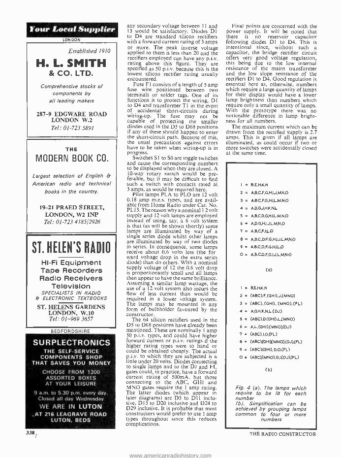
It is probable that 15 lamps is about the minimum quantity that is capable of indicating numerals from 0 to 9. In the design described here, they are set up in 5 horizontal rows of 3 lamps, as illustrated in Fig. 1. The letters from A to O which appear in the diagrams are intended to provide references for the purpose of explanation in this article, and they do not in practice appear alongside the lamps.
Numbers are indicated by illuminat- ing some of the lamps only, as illus- trated in Fig. 2. Thus, the number 1 is
336
given by having the central vertical line of lamps lit up, as is shown. The patterns representing the succeeding numbers will also be recognised. In Fig. 2 the non -illuminated lamps are indicated by the black circles, and are included for the sake of completeness. In practice, the pattern presented by the illuminated lamps is more readily
15 pilot lamps
O O O A ß C
Q?? O O O
G H
O O O J K L
O O O M N O
Fig. 1. The fifteen lamps which form the display are laid out in five horizontal rows
recognisable than would appear from Fig. 2. because the non -illuminated lamps simply become part of the back- ground and do not distract the atten- tion of the viewer. This effect can be checked by covering the black dots for any number in Fig. 2 with one or more pieces of paper.
It is intended that each pattern in Fig. 2 be selected by closing one of ten s.p.s.t. on -off switches. It is obviously necessary for each switch to select its own pattern of lamps only, and that some form of electrical isolation between patterns must, in consequence, be provided. A simple method of obtaining this isolation consists of using diode OR -gates at each lamp in the manner shown in Fig. 3. Pilot lamp K in this diagram appears in both the number 1 pattern and in the num- ber 4 pattern. When the upper switch, designated '1', is closed, current flows to the pilot lamp from the positive supply point via the upper diode. The lower diode prevents this current flowing to the switch designated '4' where it would cause the other lamps which make up the number 4 pattern to be illuminated. Similarly, if the switch labelled '4' is closed and that labelled '1' is open, lamp K is illumi- nated by the current which flows through the lower diode, whilst the upper diode prevents this current passing through to the number 1 lamp circuit. In practice the diodes would be silicon rectifiers.
It follows from Fig. 3 that each of the patterns of Fig. 2 could be repro- duced by having a diode at each lamp for each switch circuit. The requisite lamp combinations for each number are shown in Fig. 4(a), the letters corresponding to those in Fig. 1. Thus, number 1 is given when lamps B, E, H, K and N are illuminated, and so on.
THE RADIO CONSTRUCTOR
www.americanradiohistory.com

o 000 000 0 O O o 0 o= 000=2 000=3 00=4 0 0 0 000 o 000 000 O 000 o 000=5 O 000
O 000 000 000 000 O o oo oo oo 000 =6 o =7 000 =8 000 =9 00 =0 oo o oo o oo 000 o 000 o 000
Fig. 2. The lamps are illuminated to represent numbers from 1 through to 0 in the manner shown here
If we are to use the simple diode concept shown in Fig. 3, we will require a diode for each letter in Fig. 4(a), this representing a total of 98 diodes.
However, several groups of letters appear in four or more number patterns, and it is possible to reduce the number of diodes required by grouping these lamps. Each group then requires only one diode for each switch position. The consequent sim- plification is shown in Fig. 4(b), in which it will be seen that lamps (ABC), (GHI), (MNO), (DJ) and (FL) are bracketted together. This simplification reduces the overall number of diodes required to 64 and is patently well worth -while carrying out. A further simplification could be given by using (ABCGHI) as a group, and this would save 2 further diodes. However, an (ABCGHI) group would require series isolation diodes with a forward current rating higher than the nominal 1 amp figure which is specified here, and it was felt that the consequent complications would not merit the saving of 2 diodes.
Some years ago a circuit of this nature incorporating 64 diodes would have been considered prohibitively expensive, Nowadays, though, silicon rectifiers are available at exceptionally low prices and the total cost of com- ponents for the circuit can be kept relatively low. A further economy could be effected by purchasing a batch of `untested' diodes, as are sold from time to time at very low cost, or by buying surplus equipment from which diodes may be removed. JANUARY 1972
OPERATION
The overall operation of the circuit is illustrated in Fig. 5. Here, the second- ary of mains transformer Ti offers 12.6 volts at a current rating of 3 amps to the bridge rectifier given by D1 to D4. The negative output from the bridge rectifier provides a common connection for all the pilot lamps, whilst the positive output is applied, via fuse F1, to switches S1 to SO, and thence to the main diode circuits. Outputs from the diode circuits couple to the ABC, GHI, MNO, DJ and FL gates, which connect to their appropriate groups of lamps. Further
outputs are taken to the individual lamps. The actual diode and gate circuits will be introduced and des- cribed when the constructional details are given; to reproduce them in Fig. 5 would result in a complex diagram that would be difficult to follow.
So far as components are concerned, T1 is any mains transformer providing 12.6 volts at 3 amps or more, and may conveniently consist of a valve radio mains transformer having two 6.3 volt 3 amp heater windings which are connected in series. The h.t. winding on such a transformer is ignored. The actual voltage provided by the trans- former is not particularly critical and
-ED Pilot lamp
K
Fig. 3. Illustrating the basic OR -gate circuit which allows the number patterns to be isolated from each other
337
www.americanradiohistory.com
Your Local Supplier LONDON
Established 1910
H. L. SMITH & CO. LTD.
Comprehensive stocks of components by
all leading makers
287 -9 EDGWARE ROAD LONDON W.2 Tel: 01 -723 5891
THE
MODERN BOOK CO.
Largest selection of English &
American radio and technical
books in the country.
19-21 PRAED STREET, LONDON, W2 1NP Tel: 01 -723 4185/2926
ST. HELEN'S RADIO
Hi -Fi Equipment Tape Recorders Radio Receivers
Television SPECIALISTS IN RADIO
& ELECTRONIC TEXTBOOKS
ST. HELENS GARDENS LONDON, W.10 Tel: 01 -969 3657
BEDFORDSHIRE
SURPLECTRONICS THE SELF -SERVICE
COMPONENTS SHOP THAT SAVES YOU MONEY
CHOOSE FROM 1200 ASSORTED BOXES AT YOUR LEISURE
9 a.m. to 5.30 p.m. every day. Closed all day Wednesday
WE ARE IN LUTON AT 216 LEAGRAVE ROAD
LUTON, BEDS
338
any secondary voltage between 11 and 13 would be satisfactory. Diodes D1 to D4 are standard silicon rectifiers with a forward current rating of 3 amps or more. The peak inverse voltage applied to them is less than 20 and the rectifiers employed can have any p.i.v. rating above this figure. They are specified as 50 p.i.v. because this is the lowest silicon rectifier rating usually encountered.
Fuse F1 consists of a length of 5 amp fuse wire positioned between two terminals or solder tags. One of its functions is to protect the wiring, DI to D4 and transformer T1 in the event of accidental short -circuits during wiring -up. The fuse may not be capable of protecting the smaller diodes used in the D5 to D68 positions if any of these should happen to enter the short -circuit path. Because of this, the usual precautions against errors have to be taken when wiring -up is in progress.
Switches S1 to SO are toggle switches and cause the corresponding numbers to be displayed when they are closed. A 10 -way rotary switch would be pre- ferable, but it may be difficult to find such a switch with contacts rated at 3 amps, as would be required here.
Pilot lamps PLA to PLO are 12 volt 0.18 amp m.e.s. types, and are avail- able from Home Radio under Cat. No. PL13. The reason why a nominal 12 volt supply and 12 volt lamps are employed instead of using, say, a 6 volt system is that (as will be shown shortly) some lamps are illuminated by way of a single series diode whilst other lamps are illuminated by way of two diodes in series. In consequence, some lamps receive about 0.6 volts less (the for ward voltage drop in the extra series diode) than do others. With a nominal supply voltage of 12 the 0.6 volt drop is proportionately small and all lamps then appear to have the same brilliance. Assuming a similar lamp wattage, the use of a 12 volt system also incurs the flow of less current than would be required in a lower voltage system. The lamps may be mounted in any form of buibholder favoured by the constructor.
The 64 silicon rectifiers used in the D5 to D68 positions have already been mentioned. These are nominally 1 amp 50 p.i.v. types, and could have higher forward current or p.i.v. ratings if the higher rating types were to hand or could be obtained cheaply. The actual p.i.v. to which they are subjected is a little under 20 volts. Diodes connecting to single lamps and to the DJ and FL gates could, in practice, have a forward current rating of 500mA, but those connecting to the ABC, GHI and MNO gates require the 1 amp rating. The latter diodes (which appear in later diagrams) are D5 to D1 inclu- sive, D15 to D20 inclusive and D24 to D29 inclusive. It is probable that most constructors would prefer to use 1 amp types throughout since this reduces complications.
Final points are concerned with the power supply. It will be noted that there is no reservoir capacitor following diodes Dl to D4. This is intentional since, without such a capacitor, the bridge rectifier circuit offers very good voltage regulation, this being due to the low internal resistance of the mains transformer and the low slope resistance of the rectifiers D1 to D4. Good regulation is essential here as, otherwise, numbers which require a large quantity of lamps for their display would have a lower lamp brightness than numbers which require only a small quantity of lamps. With the prototype there was no noticeable difference in lamp bright- ness for all numbers.
The maximum current which can be drawn from the rectified supply is 2.7 amps. This is given if all lamps are illuminated, as could occur if two or more switches were accidentally closed at the same time.
I = B,E,H,K,N
2 = A.B,CF,G,H,I,J,MN.O
3 = A,B.C,F,G,H,I,L MN,O
4 = A,D,G,J.H,KN,L
5 = A,B,C,D,G,HJ L M,N,O
6 = A,D.G,H,6J,L,M,N,O
7 = A,B,C,F,I,LA
8 = A,B,C,D,F,G,H,IJ,LMN,O
9 = A,B,C,D,F,G,H,IJ-O
O =
(4)
=
2 = (ABC),F,(GHI),J,(MNO)
3 = (ABC), (GHI), (MNO),(FL)
4 = A,GN,K,N,L,(DJ)
5 = (ABC),D,(GHI),La(MNO)
6 = A,L,(GHI),(MNO),(DJ)
7 = (ABC),I,O,(FL)
8 = (ABC),(GHOCMNO),(DJ),(FL)
9 = (ABC),(GHI), D,O,(FL)
O = (ABC),(MNO),G,I(DJ),(FL)
(b)
Fig. 4 (a). The lamps which require to be lit for each number (b). Simplification can be achieved by grouping lamps common to four or more
numbers
THE RADIO CONSTRUCTOR
www.americanradiohistory.com

AC moins
1
:12.6V 3A
F1
54 a
D3
PLA- PLO
- 12V, 0.184
D1-D4
-3A, 50 P.I.Y.
D5- D68
- IA,50 P.I.V.
17
Si-,11-6
Diode circuits
D46-
-D68
ABC
Gate D5-014
GHI Gate
D15 -D23
1-A ,- B
-1C
MNO
Gate
D24'D32
DJ Gate
D33 -D38
FL F Gate
D3F-Dq5 L
o A
B
C D
E ) F
G f H
I
J
K L
M
W N
/0
Pilot lamps
C
D OD E
G
H H
J t OJ e
O
Fg. 5. Overall circuit of the display unit. This may conveniently be made up in two sections, these being separated here by the vertical dashed line
CONSTRUCTION
In dealing with the construction we shall also be able to describe the individual diode circuits. This approach is employed because it avoids the reiteration of circuit information. Also, it is important to understand what each wiring step achieves and this again involves a
discussion of circuit operation. JANUARY 1972
The method of mechanical construc- tion is left to the reader. For most applications, it will be required that the lamps be fitted on a flat board behind which is mounted the circuitry incor- porating diodes D5 to D68. An 11 -way lead can then connect this board to the power supply negative output and to switches Sl to SO. These, together with the mains transformer, FI, and Dl to D4, are then positioned at a convenient
control point. The two separate sections appear on either side of the vertical dashed line in Fig. 5.
It will be necessary to fit an I l -way tagstrip on the board, ten tags of which are numbered through from 1 to O.
The II -way lead from the switch section will connect to this, the switch numbers corresponding to the tag numbers. The eleventh tag will be for the common negative supply line.
339
www.americanradiohistory.com

Your Local Supplier HAMPSHIRE
BOURNEMOUTH LARGEST HI -FI AND RADIO COMPONENT STORE IN THE SOUTH
FORRESTERS NATIONAL RADIO SUPPLIES LTD. 70 -72 Holdenhurst Road
Bournemouth Telephone 25232
NOTTINGHAM
ARE YOU LOST FOR THAT VITAL
SCREWP
0 -8 BA screws, nuts & washers in Brass. Copper, brass & aluminium sheet cut to your requirements. Electric soldering irons & bits.
S.A.E. List. Callers to our trade counter welcome. Hours 8.30 -5.00 Mon -Fri.
8.30 -12.00 Sat.
The D.Q. Engineering Co. Ltd., Kirkby Folly Road, Junction Mills,
Sutton -in- Ashfield, Notts. Telephone Sutton -in- Ashfield 5785
SUSSEX
E. JEFFRIES For your new television set
tape recorder, transistor radio and hi -fi equipment
PHILIPS, ULTRA, INVICTA DANSETTE, MASTERAD /O, PERDIO,
MARCONI, PHIL CO FIDELITY
6A Albert Parade Victoria Drive,
EASTBOURNE SUSSEX
YORKSHIRE
WILSIC ELECTRONICS LTD. Your local supplier for
EAGLE PRODUCTS CYBERNAT MOTORING AIDS
WILSIC HI -FI, MUSICAL EQUIPMENT, KITS, AND
COMPONENTS OUR CATALOGUE FREE
Postage 5p Eagle Products Catalogue
Postage 5p 6 COPLEY ROAD DONCASTER
340
From switches
From switches
{
(a)
From switches.,
(b)
To pilot lamps
G
H To pilot lamps
(c)
To pilot lamps
Fig. 6. Gate circuits for (a) the ABC group, (b) the GHI group, and (c) the MNO group
More than one connection will be made to the positive lamp terminals and it should be adequate to provide each positive tag with a 3 -way tag - strip having all tags commoned to take the connections. This does not, how- ever, apply to the positive terminal of pilot lamp K, to which only two connections are needed. Tagstrips will also be required for diode junctions for the five gates and to augment the tags of the 11 -way tagstrip just mentioned. Physical layout of com- ponents is unimportant and, as the parts used are all small in size, the rearward projection from the back of the lamp board should be small.
The first part of the construction consists of assembling and wiring Ti, Dl to D4, FI, and SI to SO. The
switches and the negative supply rail should next be connected to the 11 -way tagstrip on the lamp board. Add, also, a temporary fly -lead connecting to the junction of F1 and the switches. The other end of this fly -lead is used to provide a positive test voltage for circuit checking during construction.
Next, fit all the bulbholders and insert the bulbs. Wire up the common negative terminals of all bulbholders. Apply the mains to TI and check the supply by connecting the positive fly - lead to the positive terminal of any bulb. This should light up brightly without any flickering. Take care to ensure that the positive fly -lead does not accidentally touch any negative point.
The next process consists of wiring
THE RADIO CONSTRUCTOR
www.americanradiohistory.com

up the gates. Each gate is checked after wiring because mistakes here can be rather difficult to trace later. Take great care to connect each diode with correct polarity and, if the diodes are of the 'untested' variety, check them also for short -circuit junctions before connecting them into the circuit. A short -circuited or reversed diode can cause confusing results. It should be noted that the diode cathodes are always towards the lamps, i.e. the ' '
side of each diode is on the lamp side and the 'arrow -head' of the diode circuit symbol 'points' towards the lamps.
Fig. 6(a) shows the ABC gate, and its mode of operation will be evident from consideration of the OR -gate shown in Fig. 3. The positive terminals of the ABC group of lamps are coupled to D12, D13 and D14, and thence to the further isolating diodes D5 to D11. Lamps A, B and C appear in the num- bers 2, 3, 5, 7, 8, 9 and 0, and in consequence the group is wired to the correspondingly numbered switches. Thus, closing any of these switches
switches is closed. The GHI gate, shown in Fig. 6(b),
comes next. This functions in a similar manner to the ABC gate, and the GHI lamps become illuminated when any of the numbers 2, 3, 5, 6, 8 and 9 is selected. After wiring, first apply the positive test fly -lead to the junction of the two sets of diodes, whereupon the lamps G, H and I should light up. They should also light up when either S2, S3, SS, S6, S8 or S9 is closed.
The third gate, that for lamps M, N and O, is illustrated in Fig. 6(c). After wiring, check with the positive test fly -lead at the junction of the two sets of diodes and then confirm that lamps M, N and O light up when either S2, S3, S5 S6, S8 or SO is closed.
Figs. 7(a) and (b) give the circuits for the DJ and FL gates respectively. These operate in the same manner as the previous gates. First wire up the DJ gate, checking with the positive test fly -lead at the junction of the two sets of diodes, and then confirm that lamps D and J light up when either S4, S6, S8 or SO are closed. Next, wire up
From switches
From switches
(a)
(b)
To pilot lamps
To pilot lamps
Fig. 7. Circuits for (a) the DJ group and (b) the FL group
causes lamps A, B and C to be illuminated, the diodes in the gate preventing any other circuits from being affected. Wire up the diodes as illustrated, then check the circuit by first applying the positive test fly -lead to the junction of the two sets of diodes, i.e. to the common negative ends of D12, D13 and D14. All the three lamps, A, B and C, should then light. Next ensure that all three lamps are illuminated when any of the associated JANUARY 1972
the FL gate, similarly test with the positive fly -lead and then with switches 53, S7, S8, S9 and SO. The positive test fly -lead is now no longer required and may be removed.
If, during any of the gate tests, more than the selected lamps become illuminated, the fault probably lies in a short -circuited diode fitted in an earlier step. It is for this reason that it is advised that diodes of doubtful performance be checked before they
Four Local Supplier YORKSHIRE
PERFECT SPEAKERS Ex TV. P.M. 3 Ohm (Minimum order 2)
5in. Round or Bin. x 21in. 121p each Add 74p per speaker p. Et pkg.
100 SPEAKERS for £15 delivered 200 SPEAKERS for £25 delivered
UHF TUNERS Ex TV. (COMPLETE WITH VALVES) £2.50 each plus 50p p. Et pkg.
or 10 for £23 post free
TRADE DISPOSALS (Dept. RC) Thornbury Roundabout, Leeds Road, Bradford Telephone: 665670
EIRE
PEATS for PARTS ELECTRONIC COMPONENTS
RADIO & TELEVISION
For the convenience of Irish enthusiasts we supply
The Radio Constructor Data Books and Panel -Signs Transfers
Also a postal service
Wm. B. PEAT & Co. Ltd. 28 PARNELL STREET
DUBLIN 1
The RADIO CONSTRUCTOR
ANNUAL
SUBSCRIPTIONS to this magazine may be obtained
through your newsagent
or direct from the publishers
ONLY £2.70 per year, post free Please send remittance with name and address and commencing issue required to:
DATA PUBLICATIONS LTD 57 Maida Vale London W9 1514
341
www.americanradiohistory.com

AUDIO
AMPLIFIERS
16 Transistor & Valve Designs for the Home Constructor
Amplifiers for Tuner Units, Record Players,
Tape Recorders, Public Address, etc., etc.
Includes contributions by such well -known authors as
A. S. Carpenter, A. Kinloch, E. Govier, G. A. French, F. G. Rayer, P. F. Bretherick, K. Jones, D. Aldous, R. Murray -Shelley, C. Swires, G. A. Stevens and V. E. Holley
Edited by J. R. Davies
124 pages
PRICE 53p Postage 6p
To: DATA PUBLICATIONS Ltd., 57 Maida Vale London W9
Please supply copy (ies ) of "Audio Amplifiers ", Data Book No. 18. I enclose cheque/
crossed postal order for
Name
Address
RC
BLOCK LETTERS PLEASE
342
From S2
From 53
From 54
(a)
2
D51
(b)
3
4
(c)
To pilot lamps
ABC Gate (already wired)
GHI Gate (already wired)
MNO Gate (already wired)
J }To pilot lamps
ABC Gate (already wired)
GHI Gate (already wired)
MNO Gate (already wired)
FL Gate (already wired)
DJ Gate (already wired)
5 From 55
(d)
(e)
To pilot lamps
ABC Gate (already wired)
GHI Gate (already wired)
MNO Gate (already wired)
L } To pilot lamps
Fig. 8. Wiring for (a) the number 1 display, (b) the number 2 display, (c) the number 3 display, (d) the number 4 display and (e) the
number 5 display
are fitted. If a diode is wired in with reverse polarity, the corresponding lamp or switch circuit will not func- tion; and this is one reason why each wiring step should be checked before proceeding further. A reverse -con- nected diode can cause lamps other than those selected to be illuminated,
and would be difficult to trace if the circuit were wired up in its entirety without testing after each step.
The number 1 display pattern comes next. This does not use any of the groups which have just been wired up but simply causes lamps B, E, H, K and N to light up. The circuit is as
THE RADIO CONSTRUCTOR
www.americanradiohistory.com

Fig. 9. Further number pattern circuits. That in (a) is for num- ber 6, (b) number 7, (c) num- ber 8, (d) number 9, and (e)
number O.
From 56 6
GHI Gate (already wired)
MNO Gate (already wired )
(already 061
DJ Gate wired)
D62
A To pilot lamps
L
(a)
ABC Gate (already wired)
7 FL Gate (already D63
wired) From 57
D64
I
To pilot lamps O
From 58
From 59
(b)
8
(c)
ABC Gate (already wired)
GHI Gate (already wired)
MNO Gate (already wired)
DJ Gate (already wired)
FL Gate (already wired)
ABC Gate (already wired)
GHI
D65
Gate (already wired)
FL Gate (already wired)
D66
(d)
(e)
D
To pilot lamps O
ABC Gate (already wired)
MNO Gate (already wired)
DJ Gate (already wired)
FL Gate (already wired)
G To pilot lamps
shown in Fig. 8(a), in which SI connects directly to diodes D46 to D50. These, in turn, connect directly to the positive terminals of the lamps concerned. The lamps should become iLuminated when Si is closed.
Number 2 follows. This uses the gates ABC, GHI and MNO, which have already been wired up. See Fig. 8(b). It only remains to make connec- tion to lamps F and J via D51 and D52, as shown. When S2 is closed the lamps should display the number 2.
Number 3 is next. This has already been wired up since it uses group gate JANUARY 1972
circuits throughout. as illustrated in Fig. 8(c). The number 3 should be displayed when S3 is closed.
The next number is 4, and this is wired up as in Fig. 8(d). Diodes D53 to D58 are wired into circuit as shown, the group DJ being already connected up. Check that the number 4 is displayed when S4 is closed.
Proceed in the same manner with number 5, as in Fig. 8(e), then carry on to numbers 6 and 7, as in Figs. 9(a) and (b) respectively. Number 8, shown in Fig. 9(c), is already fully wired, and only requires checking. The final two
numbers are 9 and 0, and these are connected up as in Figs. 9(d) and (e) respectively.
After these last two numbers have been wired and tested, the digital display unit is complete and ready for use. The amount of wiring required may appear rather extensive, but this is largely because the constructional steps have been described in terms of circuit function. The prototype unit, assembled by the author to test the circuit, was wired up in the course of an afternoon.
343
www.americanradiohistory.com

Trade News .. 'NIPPIBOARD' PRINTED CIRCUITS
A new departure in the field of printed wiring boards is announced by NIP Electronics, whose product Nippiboard' is now available to readers. Nippiboard' consists of ready - printed circuit board having a copper pattern which has been specifically designed to provide a `bread- board' for semi- conductor circuits.
The essential feature of Nippiboard' is that the copper pattern is particularly intended for transistor amplifiers, oscillators, timers, switching circuits and similar configura- tions. Each Nippiboard' pattern module, which is approxi- mately 2 in. long and 1 ¡in. wide, has a copper layout which is symmetrical about the centre line along the tin. length. There are two unbroken copper strips at top and bottom for supplies, whilst the intervening copper pads are designed to take the number of components they will normally be expected to provide connection for in transistor circuits. A small pattern module can take up to four or five transistors. The copper sections are provided with a matrix of small marker holes, these being identified by the numbers 1 to 16 along the 2in, length, and by the letters A to M along the 1 } in. width. The numbers and letters are part of the copper print and the overall pattern is copyright by NIP Electronics.
After the user of Nippiboard' has decided on the circuit design to be employed, this is marked up with the `Nippi- board' number- letter references, after which the correspond- ing holes are drilled in the Nippiboard' base to take com- ponent lead -outs. The components can then be soldered to the board in the usual manner.
Nippiboard' is available with an s.r.b.p. ('Paxolin') or a fibreglass base, and is flux varnished on the copper side to prevent oxidation and to ease soldering. The board is available in a wide variety of sizes, these ranging from a base carrying a single pattern module to a base carrying ten of the patterns in two rows of five. Further details may be obtained from NIP Electronics, P.O. Box 11, St. Albans, Herts. 344
U.H.F. AND V.H.F. DIODES Motorola Semiconductors have introduced new ranges of
voltage -variable- capacitance tuning diodes, p.i.n. switching diodes, mixer diodes and detecting diodes for use in v.h.f. and u.h.f. applications, primarily television. All of these diodes are housed in an axial -lead `MINI -L' plastic casing which has been specially designed to have a very low lead inductance of typically 3.0 nanoHenries. The L- shaped case clearly identifies the cathode for ease of testing and insertion into printed -circuit boards.
Continuously -variable tuning in the v.h.f. band is the function of the MV 3140 -42 series voltage- variable -capacit- ance diodes. These have a nominal capacitance of 2.1 pF at 25 V and capacitance can be varied over a 4.5:1 ratio. The minimum Q value, measured at 100 MHz, is 150.
Continuous tuning over the v.h.f. band is catered for by the MV 3102 -03 series 'Epicap' tuning diodes. These exhibit typical capacitance ratios of 4.8:1, a minimum Q value, at 300 MHz, of 300 and a nominal capacitance of 22 pF at 3 V d.c.
These two series of tuning diodes can be obtained in com- puter- matched groups in which capacitance values can be matched to ± 1.5% or 0.1 pF (whichever is the greater) over the specified tuning range. Devices in these matched groups are rated at 30 V maximum reverse voltage.
Band -selection at v.h.f. is greatly simplified by the MPN 3401 -02 p.i.n. switching diodes. These enable components to be switched into or out of circuit merely by application of d.c. bias voltages, eliminating the need in television and similar applications for bulky turret tuners.
Two Schottky `hot carrier' diodes, types MBD -502 and MBD -702, are for use in high -efficiency u.h.f. and v.h.f. detectors. They are rated at 50 and 70 V, respectively.
A third Schottky diode, type MBD -102, is primarily for u.h.f. mixer applications. It has a noise figure of 5.5 dB at 1 GHz.
In quantities of 100 and more, prices per 100 are: £20.00 to £40.00 for the MV 3140 -42 u.h.f. tuning diodes, £35.00 and £27.50 for the MV 3102 -03 v.h.f. tuning diodes, £18.90 for the MPN 3401 -02 p.i.n. diodes, and £110.00 to £38.50 for the MBD Schottky diodes.
THE RADIO CONSTRUCTOR
www.americanradiohistory.com

TRANSISTOR STABILIZED POWER UNIT
By
P. CAIRNS, M.I.P.R.E., G3ISP
PART 2
In this concluding article constructional details are given for the power supply whose circuit was described last month. It offers an
output that is continuously variable from 6 to 36 volts.
CONSTRUCTION
THEE UNIT IS MADE AS COMPACT AS POSSIBLE AND,
the case and dimensions used by the writer are specified, a larger cabinet and different layout
may be adopted to meet individual choice. There is nothing critical about component configuration.
The electronic components are wired on a I2 -way tagboard. The tagboard employed by the author had dimensions of 11 by 3.1in., as shown in Fig. 4. If an exactly similar board cannot be obtained, a suitable alternative is a 12 -way miniature tagboard measuring 1. by nin. available from Henry's Radio, Ltd. The
author's version of the tagboard assembly incorporated a Mullard silicon bridge rectifier for D1 which, at the time of writing, is not readily available through the usual retail channels. Other miniature silicon bridge rectifiers, such as the type 2002 available from Henry's Radio, can be used instead provided, of course, the ratings are adequate. Alternative rectifiers may have different lead -out layout to that shown in Fig. 4, which illustrates the tagboard wiring. The components are connected up as shown, after which the tagboard is mounted vertically on the chassis by means of a narrow angle bracket. All outgoing flyleads can be connected to the board before it is mounted in position. The
c b e
31/2"
Neg. out TR1.c C2 .MI
R4 D2 C4
4b
TRi.b VR1
R5 R6 R7
e VR1
12 -way tag -board Links
FI Ti sec.
g \
ggggSS
RM1 ¿ \` RI
S \
`v RM2
C1-C2 TRI.e and C1
Fig. 4. Component assembly on the 12 -way tagboard. The links, shown in broken line, are behind the board
JANUARY 1972 345
www.americanradiohistory.com

-E. a N
s .x_ ` Ñ « Q v LL
m o in
Ñ
ó 2
uNi
al co
346
V
THE RADIO CONSTRUCTOR
www.americanradiohistory.com

chassis can be simply made from an aluminium plate with a lip bent along the front edge for fixing to the front panel. Side angle struts should be mounted between the chassis and front panel for extra strength. The transformer and heat sink with smoothing capa- citors are all mounted on the chassis, the complete layout with all relevant dimensions being shown in Fig. 5. The front panel is drilled and components mounted before being screwed into place. Fig. 6 shows the front panel with dimensions.
The heat sink is made from Ain. aluminium, drilled to allow the mounting of the 0C35 and capacitor clips and then bent as shown in the heat sink details given in Fig. 7. The heat sink is also used as the anchoring point for the smoothing capacitor retaining clips. These capacitors can be mounted either by means of con- ventional clamps or, more simply, by means of insulated spring clips. If the capacitors used are of the type having the can common to negative, ensure that the can is insulated from chassis. When the capacitor is mounted in place a strip of insulating tape or heavy polythene between can and clamp is suitable.
As the heat sink is mounted directly on the chassis the 0C35 must be insulated electrically from the metalwork by means of a mica washer and insulating bushes for the two fixing screws. These are standard items and can be bought with the transistor. Since it is extremely important that the transistor should have a good thermal junction with the heatsink, any burrs and rags on the holes drilled should be removed and the mounting surface rubbed over with fine emery cloth so as to present a completely clean, smooth surface. A smear of silicon grease should be placed between the transistor face and mica washer and between the mica washer and heat sink surface. The transistor is then clamped down firmly by means of the two fixing screws. Before mounting on the chassis the complete surface of the heat sink, apart from that immediately beneath the 0C35, should be given a coat of matt black paint, the surface being rubbed over first with emery cloth to give the paint a hold. The heat sink details have been stressed since the correct preparation and mounting of the transistor is extremely important if good thermal contact and good heat dissipation are to be achieved.
METERING CIRCUIT
The metering circuit will be rather dependent upon the type of meter used. With the 10mA movement speci- fied the series resistor, RM2, will have a value of 5k S2
for a 50 volt full -scale reading, such a movement having a sensitivity of 1005 per volt. The accuracy will of course depend upon the accuracy of the resistance used and the quality of the meter. At least a 5% high stability type is advised while a 1% or 2% type is preferable.
The shunt resistor RM1 will have to be made by hand, the actual value being dependent upon the internal resistance of the meter, the value of which will vary with different makes and types. The shunt value
can be calculated from Rs = Rm
, Rm being the meter
resistance and n the range multiplying factor. As an example, the resistance of the meter used by the writer was 30, therefore the value of Rs to give a full -scale
3 reading of 1 amp (100 times factor) was
100 - 1 or
0.03035. Say 0.035. As the shunt value will always JANUARY 1972
be very small it can be simply made from a few inches of Eureka or Nichrome resistance wire wound on a I or tin. diameter former. A gauge of wire is chosen which will carry 1 amp without overheating. Using the example just given, 18 s.w.g. Eureka has a resistance of 0.3845 per yard and Nichrome a resistance of 0.8545 per yard; therefore a length of 2.81 in. of the Eureka or 1.26 in. of the Nichrome would give the required shunt value. An extra fin. at each end should be allowed for soldering and connection. (18 s.w.g. wire, both in Eureka and in Nichrome, is available from Post Radio Supplies, 33 Bourne Gardens, London, E4 9DX). Conversely, any piece of heavy resistance wire out of the junk box can be cut down to size experimentally by connecting the meter in series with another ammeter and an external supply and load. The length of wire is reduced until the readings on both meters are the same. Take care to ensure that, due to a poor connection, an excessively high current cannot be passed through the meter on its own. The test
-13/g+.. e"
Cabinet fixing
13/g'+.,
r
21/2+
ns1
FI
21/4"
6BA fixing
Side struts
I
t
IN* 3/4a kOá-=¡'==__=
Output terminals
Chassis
4 6BA fixing
Fig. 6. Layout and dimensions of the front panel
current should be established in the resistance wire first, the meter to be shunted then being temporarily connected to the wire. When the shunt is completed it is advisable to make a final check on both current and voltage calibration before the meter and compon- ents are put into circuit. The voltage and current ranges on the average multimeter will be sufficiently accurate for calibration checks.
FINAL DETAILS
For those who, like the writer, prefer to wind their own transformers and can obtain the laminations re- quired, the following details are included. Core, Stalloy lin. square interleaved stack, window space lj by sin. Primary, 2,000 turns 32 s.w.g.; secondary 285 turns 20 s.w.g. Allow suitable insulation on primary and between windings.
With the heat sink and other components all in position, the front panel can be screwed into place and the various interconnections made off. Ensure that the output terminals are insulated from the panel. The mains input is brought in from the rear of the chassis and taken to a 3 -way terminal block secured with
347
www.americanradiohistory.com

55/8 11/2*
41/2°
lie
TRI
"-O /
Collector tag
bend in
o o
48A fixing TRI
.o o
Heat sink.
1/16" aluminium.
Painted matt black
Mica washer
Insulated bushes
Nuts - Heat sink
Collector tag
Fig. 7. Details of the heat sink and method of mounting TR i
Araldite to the top of the transformer. Alternatively a suitable tag -strip can be mounted under one of the core securing bolts or at any other convenient point. A 3-core mains lead is employed, the earth being taken only to the transformer core and chassis. This means that the chassis, front panel and all metalwork inside the unit are safely earthed, while the d.c. supply is floating. The layout and appearance of the completed power unit is clearly shown in the photographs.
Final testing should offer no problems. With VR1 set to about mid -point and the meter switched to read voltage, connect the mains supply. The meter should immediately indicate some reading about the middle of the voltage range. If internal metering is not used connect a d.c. voltmeter across the output terminals and switch on Sl. VR1 can be varied over its entire
TABLE II Voltage Readings
All readings measured with 20kû per volt instrument with respect to negative line. Vout = 20, Iout = 0.25A. Transformer secondary 34.6V a.c. TR1 Emitter 42.9V
Base 42.7V Collector 20V
TR2 Base 0.55V Collector 41V
TR3 Emitter 5.61V Base 5.2V Collector 0.6V
348
Screws
travel, whereupon the voltage reading should vary appropriately over the quoted range. Some slight tolerance can be expected on upper and lower limits, principally due to transformer, zener and divider differences. These voltage differences should be quite small, however.
If desired the regulation can be checked, a suitable load being connected across the output terminals and any difference between load and no -load voltage readings noted. The load can be quickly switched in and out by means of S1. The load current can also be checked by switching S2 to the current position. As an example, with the output set to 20 volts a resistor of 4052 would be required across the output terminals to check the 0-0.5 amp regulation. Any load resistors used for test purposes should be capable of handling the necessary power. In the example just mentioned a 10 watt resistor would be necessary. To check ripple values an oscilloscope having a Y sensitivity of at least 20mV /cm is required. Should the voltage fail to stabilize at either of the extreme ends of VR1 traverse, a slight change in the value of either R5 or R6 as applicable can be made to pull TR3 base voltage within the stabilizing characteristic of the circuit. For future servicing, a list of voltage readings is given in Table II.
In practice the power unit should prove extremely useful and reliable. Its compact construction makes for portability while the wide range of voltage and current offered should meet the everyday needs of most amateur constructors and experimenters.
(concluded) THE RADIO CONSTRUCTOR
www.americanradiohistory.com

s By X
FRANK A. BALDWIN (All Times GMT)
From time to time, the writer receives letters from readers of the short wave features in this journal and, in fact, is very pleased to receive the views and comments. One such regular correspondent is B. Walsh of Romford, Essex, who by now has become a collaborator in the moni- toring of channels on which unidenti- fied stations are known to operate. Additionally, he supplies a steady stream of information on the loggings he has made to date.
One of the stations he heard was Radio Euzkadi, the Basque under- ground transmitter which operates on a measured 13220 with identification and sign -on at 2027 in English, Spanish, French, Italian and Basque. Programming is in Spanish and Basque from 2030 until 2055, then into English to explain the objects of the Basque movement. The trans- mission ends at 2103, the address given for reports being R. Euzkadi, B.P.59, Paris 16, France.
Radio Liberation, Hanoi, on 10010 in French and Vietnamese at 2015 is another of his loggings, as is CKZN, St. Johns, Newfoundland on 6160 from 2200 onwards. Considering that the power of CKZN is only some 300 watts, this represents quite a Dx feat.
PROGRAMMES IN ENGLISH
Another reader of the short wave features, whom the writer regularly meats, has frequently suggested that Dx loggings be put aside for one month and a feature made of pro- grammes in English that the average listener could, with reasonable luck, receive. So for Mr. L. E. Collop, here it is!
The times listed are those at which such programmes were actually re- ceived and those new to short wave listening should note that programme schedules are subject to change from time to time. However, many of the English transmissions will be logged by those who tune to the channels shown. 1500 9645 (31.10m) 100kW Vati-
can, identification and news. Parallel channels are 11740 (25.55m) and 15120 (19.84m).
1545 3905 (76.83m) 20kW AIR Delhi, news and identi-
JANUARY 1972
1600 6035
1830 9530
2000 9440
2000 9912
2030 9575
2100 9525
2100 9625
fication. This one may be difficult for the 'average' listener but is included for those who may care to try and receive Delhi the 'hard way'. (49.71m) 100kW War- saw, identification, news events in Poland. (31.48m) 100kW AIR Delhi, 'Press Review', Indian music. Pro- gramme beamed to Africa. (31.78m) 250kW Pekin, identification after 'East is Red' tune, news from the Chinese point of view. (30.27m) 100kW AIR Delhi, identification then newscast, Indian views on current dispute with Pakistan. (31.33m) 60 /100kW, Rome, programme about events in Italy. (31.50m) 250kW Jo- hannesburg, identifica- tion and African news, beamed to West Africa. (31.17m) 100kW Tel Aviv, identification and news.
2100 11900 (25.21m) 250kW Jo- hannesburg, tuning sig- nal at 2059, identifica- tion, 6 'pips' at 2100, then news to West Africa. (31.43m) 100kW Tema, Ghana, identification, recorded music pro- gramme. (31.76m) 50kW Karachi, Pakistan, news in Eng- lish at dictation speed.
2130 11720 (25.60m) 250kW R. Canada, identification and events in Canada.
2200 9515 (31.53m) 250kW Ankara, Turkey, identifi- cation, newscast.
2200 11970 (25.06m) 250kW Johannesburg, news- cast directed to Europe.
There are, of course, many other English language transmissions on the short waves not listed above, notable amongst which are those from Radio Moscow and the Voice of America.
2115 9545
2115 9460
LATIN AMERICA
If conditions are right, Latin America can be fairly easily received on bands other than the L.F. 60 or 90 metre portions of the spectrum. The following lists some of the LA stations operating 'higher up' the dial, the frequency being listed first, as is more usual. 9610 2115 (31.22m) 10kW ZYC9
Radio Tamoio, Brazil, talk in Portuguese after identification.
9665 2200 (31.04m) 10kW PRL Radio Nacional Brasilia, Brazil, station identifica- tion, Latin American music.
9695 2158 (30.94m) 7.5kW ZYB22 Radio Rio Mar, Brazil, sports commentary in Portuguese - all very excitable!
11720 2130 (25.60m) 10kW PRL Radio Nacional Brasilia, sports commentary. In- terference from R. Canada on same channel.
11805 2118 (25.41m) 10kW ZYZ36 Radio Globo, Brazil, talk in Portuguese and music.
11865 2115 (25.28m) 7.5kW PRA8 Radio Clube Pernam- buco, Brazil, Latin Amer- ican music, identifica- tion.
11925 2050 (25.16m) 10kW Radio Bandeirantes, Brazil, dis- cussion in Portuguese (station in Sao Paulo).
11935 2200 (25.14m) 25kW ZYS35 Radio Clube Paranaense, identification and news in Portuguese.
11965 2342 (25.07m)7.5kW PRB24 Radio Record, Sao Paulo, Brazil, discussion in Portuguese, music.
15145 2035 (19.81m) 10kW ZYK33 Radio Journal de Com- mercia, Recife, Brazil, identification and LA music.
15225 2053 (19.71m) 10kW ZYN 30 Radio Cultural da Bahia, Brazil, sports commentary.
Quite a tour of Brazil!
ODDS AND ENDS
To conclude, here are a few stations recently logged which may interest some readers. 3905 2345 (76.83m) 20kW AIR
Delhi, Indian -style music, identification in English at 2359, sign -off at midnight. (See earlier listing).
3930 2350 (76.34m) 1kW CR4AC Radio Barlavento, Cape Verde Islands, single gong note, identification in Portuguese followed by music and song pro- gramme. (76.05m) 10 /50kW Pe- shewar, Pakistan, native musical programme. (60.12m) 10kW Lagos, Nigeria, newscast in English. (59.55m) 100kW Ban- gui, Central African Republic, news in Eng- lish, identification at 2118.
349
3945 1554
4990 0505
5038 2110
www.americanradiohistory.com

NOTES ON
SEMICONDUCTORS
Further Notes -2
CURRENT AFFAIRS by
PETER WILLIAMS
This note illustrates a constant current circuit and explains how it functions.
IT IS EASY TO THINK IN TERMS OF CONSTANT VOLTAGE supplies because all the commonly available power sources are in this form - mains supplies, primary
and storage batteries. To get the most out of our electronics we should not allow ourselves to be dictated to by these supplies, but consider how we could make use of constant current supplies and then proceed to design them (or vice -versa if we are in a particularly obstinate mood).
CONSTANT CURRENT CIRCUIT
The clue to such uses lies in considering what properties of semiconductor devices and circuits depend primarily on operating current. For example a zener diode (or its transistor cousin as in `Notes on Semiconductors' in the June 1971 issue) provides a stable d.c. reference only if temperature and current are controlled. If such a diode is supplied via a resistor from a voltage supply it is at the mercy of any variations in that supply. By interposing a constant current circuit the stability of the reference can be greatly improved.
Fig. 1. shows one way of producing such a constant current. To simplify the circuit behaviour assume that the transistor has a very high gain and that Vbe is
Fig. 1. When TR 1 here has a high gain, its collector current is virtually constant despite
varying collector loads
350
negligible compared with the voltages across R1 and R2. Then I1 R1 = I2 R2, i.e. the current in R2 and hence in the transistor collector is independent of the load placed in that collector. In practice the collector current does vary at both extremes of collector voltage, but a variation of less than 1% is possible for many applications.
The higher the current gain of the transistor, the more stable the ratio of I2 to Il. If I2 is required to be stable against changes in supply voltage as well as load then either I1 has to be stabilized or R1 be replaced by an element providing a constant bias voltage. This leads to the circuit of Fig. 2 shown in complementary form as
Fig. 2. The inclusion of the zener diode Z1 guards against changes in supply voltage
a reminder that we always have this facility of circuits that `fall upwards' as well as downwards.
A zener diode between A and B would now show a high stability against changes in supply voltage and would be useful for a highly -regulated supply. A second application could be in a waveform generator using a unijunction transistor. Normally the capacitor asso- ciated with such a circuit is fed from the supply voltage via a resistor and the charging waveform is non -linear. With this modification, the constant current in the capacitor would ensure a voltage that changed linearly with time.
THE RADIO CONSTRUCTOR
www.americanradiohistory.com

RECENT PUBLICATIONS ¡III GUIDE TO PRINTED CIRCUITS. By Gordon J. King, R. Tech. Eng., M.I.P.R.E., M.I.T.A.I., F.S.R.E. 148 pages, 5¡ x 81in. Published by Fountain Press Ltd. Price £2.50.
This latest title from Gordon J. King deals with a subject which has not, perhaps, received as much attention as it should have had over the last two decades. Printed circuits started to make a significant appearance in domestic electronic equipment some fifteen to sixteen years ago. During the relatively short space of time which has elapsed since their introduction they have revolutionised manufacturing processes, and they probably provide the major reason for the relative stability of electronic entertainment product prices over a period when most other retail costs have been severely increased by inflation.
In this book, Gordon J. King does not set out to give a scientific account of printed circuits; instead he deals with them for the benefit of the amateur, the experimenter and the service engineer. After an introductory chapter, the book proceeds to describe the design and manufacture of printed circuits and then discusses how printed circuits can be made in the amateur workshop. The next chapter deals with printed circuit substitutes, including Veroboard, Cir -Kit and S -DeC systems, after which the servicing of printed circuit equipment is covered with particular reference to soldering problems and to de- soldering guns and tools. The last chapter looks into the future of printed circuits and is mainly taken up with integrated circuit applications.
'Guide To Printed Circuits' is written in the down -to -earth manner for which its author is well known, and it offers good, practical, common -sense advice to those who read it. The book is liberally illustrated with line drawings and clear photographs, and it has a useful index.
PUBLIC ADDRESS HANDBOOK. By Vivian Capel. 214 pages, 5} x 8 ¡in. Published by Fountain Press Ltd. Price £3.00.
The author of this book has had much practical experience of the installation of public address systems, and he also acts as public address engineer for a large educational organisation. This wide background is clearly reflected in the book, which deals in a practical manner with all p.a. work from simple sound reinforcement systems, as would be encountered in small clubs, to multi -watt installations in football stadia.
The book commences by dealing, in turn, with the basic principles of p.a. work, with the choice of microphones, with microphone mixers, and with amplifiers and loudspeakers. Next to be covered are the assembly of the units which make up p.a. systems and the avoidance of that bugbear of all p.a. engineers, feedback; these subjects are then followed by discussions on the best methods of obtaining both short and long term reliability and on taking advantage of auxiliary services such as Post Office lines. A further topic is the amplification of live music, including that from the electronic guitar, and the possible use of ambiophony with artistes playing in the open air or in acoustically dead surroundings. Ambiophony refers to the technique of adding, near the players, speakers which are fed with low level delayed versions of the signals produced by the players themselves. The consequent effect is of normal hall reverberation. Without such 'feedback' performers tend to subconsciously force their tone under the assumption that they cannot be heard.
Yet further chapters in this comprehensive book deal with outdoor installations, practical systems and fault finding. The section on practical systems is particularly useful as it gives examples of nine actual installations. The book concludes with the procedure involved in setting up in business as a p.a. contractor.
Public Address Handbook' can be recommended to anyone who anticipates carrying out p.a. or sound reinforcement work in the future or who has embarked on this particular segment of electronics already. The book also affords very interesting reading to those who have only a general interest in the subject of public address.
SIGNALS AND INFORMATION. By C. C. Goodyear, B.Sc., D. Phil., A. Inst.P. 318 pages, 5} x 8 }in. Published by The Butterworth Group. Price £4.20 cased, £2.80 limp.
This book is intended to offer, at final -year undergraduate level, an introduction to the theory of signals, signal processing, noise and information. Its main purpose isto offera background of communication theory for students specializing in telecommunications. The emphasis is on fundamental theory, and details of circuits and practical applications are touched on only lightly.
The author states in his preface that most students encountering the material for the first time will find that a few of the more mathematical sections take a little time to digest, and he suggests a 'first reading' sequence which enables the student to skip the more difficult sections, returning to these at a later stage.
The first chapter in the book provides an introduction to the subjects covered, whilst the second chapter covers the overall field of signals. Succeeding chapters deal with signal processing, modulation theory, probability and statistics, noise, signals with noise, informating and coding, and communication channels JANUARY 1972 351
www.americanradiohistory.com

Corer Feature NVvVV 1n
HAVING PURCHASED A LARGE QUANTITY OF ex- computer transistors, both silicon and ger- manium, the author had a requirement to classify
them; clearly some sort of tester was required, preferably direct- reading, to evaluate their performance. The same tester would also be required to check known transistors against their specifications, and to test diodes as well.
Cost was of prime importance, so initial outlay would have to be kept small, precluding the use of expensive meter movements. It was not intended to attempt to measure absolute maximum ratings or frequency limitations, thus leaving the leakage and current gain to be measured as is common with most simple transistor testers.
The most often specified leakage current in transistor data sheets is Icbo, or the current that flows between collector and base when this junction is reverse -biased at a specified voltage, the emitter terminal being unconnected. The tester was therefore designed to measure this parameter.
Two expressions for current gain exist, and an explanation of the differences will help the reader understand why the tester has been designed to measure one and not the other.
Vary Ib
o-ioo NA
O -2mA
Transistor under test
+ VCe
Fig. 1. A circuit capable of measuring d.c. gain, hFE
352
Transish A. G.
This test instrument provides ac a.c. gain by means of a bridge the necessity for an expensive n a measure of leakage current a
dii
A.C. AND D.C. GAIN
If a known quantity of current is fed to the base of a transistor, the resulting collector current can be measur- ed, and the two compared to give a gain figure. See Fig. 1.
The measurement is taken at a specified collector - emitter voltage, and the relation Ic /Ib is called the d.c. current gain, or hFE for short. This is the quantity which is most often measured in simple transistor testers. In practice, the meter in the base circuit can be eliminated by feeding the base from the collector supply via a resistance much greater than the emitter/ base resistance, in which case the effect of the latter can be ignored, and Ib calculated from Ib = Vice /Rb. See Fig. 2. Alternatively Rb can be calibrated directly
Known resistance
O -2mA
Transistor under test
+
2. If the base bias resistance is known, the base current meter can be dispensed with
in terms of Ib. (See Suggested Circuit No. 243, `Transistor Gain Checker', by G. A. French, published in the February 1971 issue.)
Although hFE gives a good idea of how a transistor will perform in- circuit, it is not an accurate measure of how much it can amplify; a better indication is given by the second expression of current gain.
This is called the `small signal current gain', or hfe for short. By definition, this is the change in collector
THE RADIO CONSTRUCTOR
www.americanradiohistory.com

1r Tester E W ETT
rate measurements of transistor ;chnique which dispenses with er. In addition, the unit can give can also check semiconductor
:s.
current resulting from a small change in the base current with Vice constant at a specified value of standing collector current and with zero load (in other words, with the collector short -circuited to a.c.). The smaller the change, the more accurate becomes the measurement. In practice, providing the change in Ic is small compared with the standing value of Ic at which the gain is to be measured, change in Ic divided by change in Ib can be taken as hfe.
This parameter could be measured using the circuit of Fig 3, in which pressing the push- button increases base current by 1 AA. The meter in the base circuit has been eliminated as in Fig. 2, and a variable resistor provided to set the standing current to, say, lmA. In order to satisfy the previous statement that the
Push to inject CI
INA
12Mn
O-2mA
Transistor under test
+12v
Fig. 3. The circuit of Fig. 2 modified to enable a. c. gain, hfe, to be measured
change in Ic must be small compared with the standing Ic, the former will have to be kept below say 1004A, which with the 0-2mA meter suggested in the diagram is going to make accurate readings difficult, to say the least.
What is required is to make the meter read only changes, and not standing values, and this can be achieved using a Wheatstone bridge, as in Fig. 4.
JANUARY 1972
If, in Fig. 4, Rl /R2= R3 /R4, then no current will flow in the meter. If R1 is replaced by the transistor under test, and it is arranged that its effective resistance is set by altering its base current so that it presents the same resistance as did R1, the bridge will again be balanced. In the basic circuit shown in Fig. 5 the supply voltage and the resistances have been chosen such that the meter zeros only when 12 volts appears between emitter and collector, and the emitter current is 1 mA. This is the standing voltage at which measurement of hfe will be made.
If a known amount of base current is now injected in addition to the standing base current, the effective resistance offered by the transistor will drop, and the bridge will be unbalanced. The reading on the meter is proportional to the amount of bridge un- balance and hence transistor gain, which can be read from a suitably calibrated meter dial.
A better (and cheaper) approach would be to replace R3 with a variable component which is calibrated in terms of gain, thereby allowing the meter to be replaced by an inexpensive but sensitive miniature stereo balance type. The variable resistance is then adjusted to achieve bridge balance, and the gain reading taken directly from it. This is the basis of the practical circuit, which is shown in Fig. 6.
353
www.americanradiohistory.com

Push to inject CI
ly A
12 Mn
Set for bridge balance
R3:R4 : 12:1
Transistor under test
R2
I kn
Fig. 5. Combining the circuit of Fig. 3 with that of Fig. 4 offers a practical means of measuring hfe
PRACTICAL CIRCUIT
In the practical circuit the four arms of the bridge are: first, the transistor emitter and collector test terminals; second, R14; third, VR4, R18 and VR5 in series; and fourth, R19 and VR6 in series.
VR2, VR1 and the resistors selected by S6 give fine, medium and coarse adjustment, respectively, of base current to bring the bridge initially into balance. The
base current is limited to 1mA maximum by Rl. When the bridge is balanced with these controls, the transistor under test will have an effective resistance of V /I= 12V /1mA =12kí2
Under these conditions, VR4, the `Gain', control is set to insert maximum resistance, thereby indicating a gain of zero. Pressing S2 causes an extra base current of 14A to be injected. If the transistor had a gain of 200 the resulting collector current (assuming an unaltered voltage drop across R14) would be lmA plus 200µA, or 1.2mA, and the effective transistor resistance would now be 12V /1.2mA= 10kí2. VR4 now needs to be in the minimum resistance position, corresponding to a gain reading of 200, for the bridge to be balanced again. So that VR4 can be made to cover the exact range of 0 to 200, VR5 and VR6 are provided as calibration controls. Only two extra resistors are required for the calibration, as will be explained later. In practice, the voltage dropped across R14 does not remain unaltered when S2 is pressed but rises to 1.2V, whereupon the effective transistor resistance becomes 11.8V /1.2mA= 9.8k0. The result- ant error is only 2 %, but its existence should be mentioned. The 2% error is given only at the maximum gain position of VR4 and becomes proportionately less at lower settings. It could, if desired, be taken up in the calibration process.
Pressing S3 instead of S2 causes 0.211A to be injected into the base, so multiplying the range by 5 and allowing gain readings from 0 to 1,000 to be given.
Another factor which affects accuracy lies in the values of R15 and R16. It is difficult to obtain close
COM PON ENTS Resistors (All fixed values ït or watt 10% unless otherwise stated)
Rl 12kí2 R2 10Mí2 R3 9.1Mí2 R4 8.2Mí2 R5 7.5Mí2 R6 6.5M0 (4.3Mí2 and 2.2Mû in series) R7 5.6Mí2 R8 4.7Mí2 R9 3.9Mí2 R10 3Mí2 R11 2Mû R12 IMO R13 12kû 5% R14 1kí2 2% R15 12Mí2 (10Mí2 5% and 2Mí2 5% in
series) R16 60MS2 (6 x 10Mí2 5% in series) R17 30kí2 R18 20kí2 5% R19 2kí2 5% R20 1kí2 2% VR1 1Mí2 potentiometer, carbon linear,
with switch S1 VR2 mow potentiometer, carbon linear VR3 25kí2 skeleton preset potentiometer
(see text) VR4 5kí2 potentiometer, 3 watt wirewound VR5 10kí2 skeleton preset potentiometer VR6 1kí2 skeleton preset potentiometer
Capacitors Cl 4,700pF, plastic foil C2 4,700pF, plastic foil
Diodes D1 AA129 (Mullard) D2 AA129 (Mullard) D3 Zener diode, 13V 5 %, 250 to 400mW
Meter M1 100-0- 10012A, moving -coil, edge
mounting
Switches Si s.p.s.t., part of VR1 S2 s.p.s.t., push- button S3 s.p.s.t. push- button S4 4 -pole 3 -way, miniature rotary S5 4 -pole 3 -way, miniature rotary S6 1 -pole 12 -way, miniature rotary
Battery B1 18 -volt battery (2 x PP6 in series)
Miscellaneous 6 pointer knobs 3 crocodile clips 3 miniature wander plugs and sockets 2 transistor holders Battery connectors Material for case and front panel Copper laminate printed circuit board
354 THE RADIO CONSTRUCTOR
www.americanradiohistory.com

tolerance resistors in the 10MS2 value incorporated in these two components. However, 5% 10MS2 resistors are available in # watt carbon from Electro- value, 28 St. Judes Road, Englefield Green, Egham, Surrey, and this tolerance should be adequate for general usage of the tester. Constructors requiring higher accuracy in R15 and R16 could make up these components with a larger number of close tolerance resistors of lower value. The author obtained all the fixed resistors for the prototype, together with VR1, from Electrovalue.
Cl and C2 prevent any rectified a.c. pick -up inter- fering with readings, and different transistor attach- ments are provided to suit various transistor lead -out configurations. These are described in the constructional notes.
When the function switch S4 is placed to `Leakage', the emitter circuit is broken by S4(c). The base current is set to zero by opening Si, which is integral with VR1. The transistor collector -base junction is now placed across the supply voltage with the meter in series with it, hence measuring Icbo at the supply voltage. R13 limits the meter current in the case of a faulty transistor. S5(c) and (d) ensure that the correct supply polarity is fed to the transistor for this test.
Power for the tester comes from two 9V batteries in
series giving 18 volts, which is stabilized down to approximately 13V due to R20 and D3. Power is applied via S4(d) in the `Leakage' and `Gain' positions. The meter is short -circuited at `Off', with S5 at either `N.P.N.' or `P.N.P.' by S4(a) and S4(b).
In the `Gain' position of function switch S4, S5(c) and (d) ensure correct polarity as before. As it was considered desirable to retain the same sense of meter pointer movement relative to the rotation of VR4 for bridge balance with both polarities, sections (a) and (b) of S5 ensure that VR4 is always turned in the desired direction of meter pointer movement to achieve bridge balance.
In the `Battery Check' position of S5, sections (a) and (b) connect the meter across R20 via VR3 and R17, the former being preset to make the meter read 5V f.s.d. Hence, provided there is deflection on the meter on this check, the batteries are still usable. Their actual voltage can be assessed, if required, with the knowledge that f.s.d. in the meter corresponds to 5V, whereupon battery voltage is equal to 13V plus meter reading. R17 is inserted in series between the positive end of R20 and S5(b) rather than in series with VR3 at the negative end of R20. If there were a direct connection between the positive end of R20 and S5(b) the battery would be momentarily short -circuited when changing
VR1 VR2
MLJvti 1MN-
RI
R2 min Transistor test
R3 socket I
I ¡Base R4 Emitter Lp I
J R5
R9
R10
RII
R12
mas.
Off
Leak°
C2
VR3 ^ NP.N. 55c
CI
R15
54c
Gain
R16
R13
ain
Leakage Off
R14
4 1
Batt.
NP N.
S5a P.N.P.
NP.N.
o 00-0-100
SSb
VR4
(gain)
RI8
VR5
(cal.)
Gain 54b Leakage
Off Batt. check
P.NP.
R1
Batt. check
VR
(set zero)
R19
N.P.N
P.N.P.
S5d il t e{ y .. check Batter
P.NP
S4d Off 11,
Gain
Bi
18V
Fig. 6. The full circuit of the transistor gain tester
JANUARY 1972 355
www.americanradiohistory.com
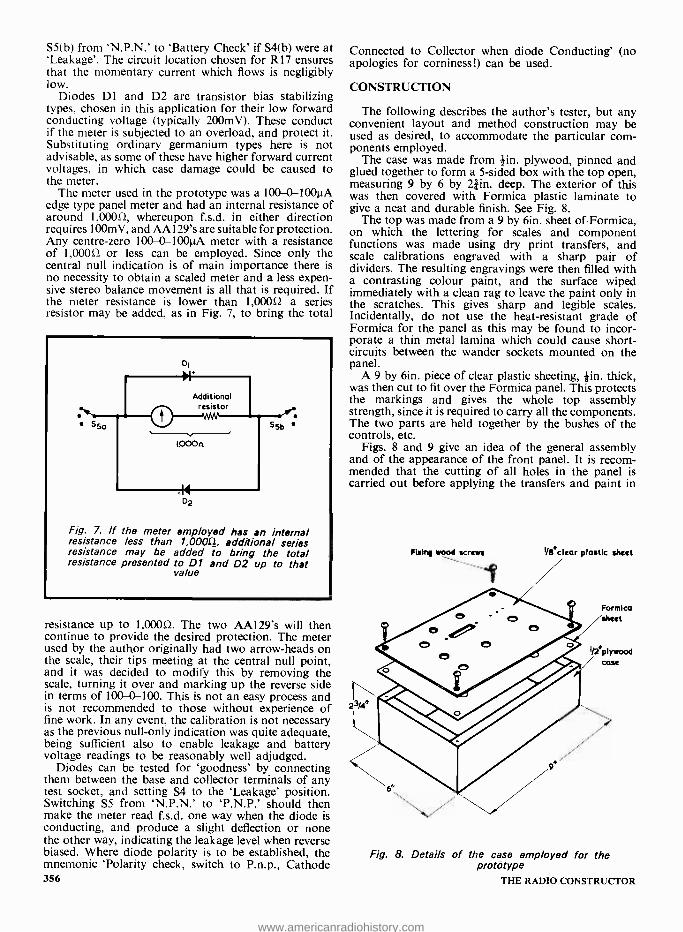
S5(b) from `N.P.N.' to `Battery Check' if S4(b) were at `Leakage'. The circuit location chosen for R17 ensures that the momentary current which flows is negligibly low.
Diodes DI and D2 are transistor bias stabilizing types, chosen in this application for their low forward conducting voltage (typically 200mV). These conduct if the meter is subjected to an overload, and protect it. Substituting ordinary germanium types here is not advisable, as some of these have higher forward current voltages, in which case damage could be caused to the meter.
The meter used in the prototype was a 100 0 100µA edge type panel meter and had an internal resistance of around 1,00052, whereupon f.s.d. in either direction requires 100mV, and AA129's are suitable for protection. Any centre -zero 100-0-100µA meter with a resistance of 1,00052 or less can be employed. Since only the central null indication is of main importance there is no necessity to obtain a scaled meter and a less expen- sive stereo balance movement is all that is required. If the meter resistance is lower than 1,00052 a series resistor may be added, as in Fig. 7, to bring the total
Fig. 7. If the meter employed has an internal resistance less than 1,000!2_, additional series resistance may be added to bring the total resistance presented to D1 and D2 up to that
value
resistance up to 1,00052. The two AA129's will then continue to provide the desired protection. The meter used by the author originally had two arrow -heads on the scale, their tips meeting at the central null point, and it was decided to modify this by removing the scale, turning it over and marking up the reverse side in terms of 100 0 100. This is not an easy process and is not recommended to those without experience of fine work. In any event, the calibration is not necessary as the previous null -only indication was quite adequate, being sufficient also to enable leakage and battery voltage readings to be reasonably well adjudged.
Diodes can be tested for `goodness' by connecting them between the base and collector terminals of any test socket, and setting S4 to the `Leakage' position. Switching S5 from `N.P.N.' to `P.N.P.' should then make the meter read f.s.d. one way when the diode is conducting, and produce a slight deflection or none the other way, indicating the leakage level when reverse biased. Where diode polarity is to be established, the mnemonic `Polarity check, switch to P.n.p., Cathode 356
Connected to Collector when diode Conducting' (no apologies for corniness!) can be used.
CONSTRUCTION
The following describes the author's tester, but any convenient layout and method construction may be used as desired, to accommodate the particular com- ponents employed.
The case was made from ¡in. plywood, pinned and glued together to form a 5 -sided box with the top open, measuring 9 by 6 by 21in. deep. The exterior of this was then covered with Formica plastic laminate to give a neat and durable finish. See Fig. 8.
The top was made from a 9 by 6in. sheet of Formica, on which the lettering for scales and component functions was made using dry print transfers, and scale calibrations engraved with a sharp pair of dividers. The resulting engravings were then filled with a contrasting colour paint, and the surface wiped immediately with a clean rag to leave the paint only in the scratches. This gives sharp and legible scales. Incidentally, do not use the heat -resistant grade of Formica for the panel as this may be found to incor- porate a thin metal lamina which could cause short- circuits between the wander sockets mounted on the panel.
A 9 by 6in. piece of clear plastic sheeting, kin. thick, was then cut to fit over the Formica panel. This protects the markings and gives the whole top assembly strength, since it is required to carry all the components. The two parts are held together by the bushes of the controls, etc.
Figs. 8 and 9 give an idea of the general assembly and of the appearance of the front panel. It is recom- mended that the cutting of all holes in the panel is carried out before applying the transfers and paint in
Fixing wood screws I /e`cicar plastic sheet
Formica /sheet
I /2`plywood case
/ Fig. 8. Details of the case employed for the
prototype THE RADIO CONSTRUCTOR
www.americanradiohistory.com

® (Min croc clips)
(Min RS plugs and sockets)
SET 1B COARSE (M1)
E
NPN
B C BATT
CHECK PNP
IB OFF SET IB
MEDIUM
MIN SET IB
FINE
®(Fixing screws) 0 -1000
POLARITY
POWER LEAKAGE GAIN OFF
himiM
S3) FUNCTION
Fig. 9. Layout and legends printed on the front panel. Items in brackets indicate component functions and do not appear on the panel
order to avoid damaging them. The cursor for the gain control knob was made from
a circular piece of clear plastic sheet, about Sin. in d_ameter, this being cemented to the knob underside with Araldite. A radial engraved line indicates the gain reading. The total potentiometer travel of VR4 can be measured using a protractor, and the result divided by 20 to obtain the scale calibrations, as shown in Fig. 9. It should be borne in mind that the first few degrees at the beginning and end of travel of some potentiometers produce no change in resistance due to the construction of the wirewound track. This can be allowed for if the end points are established using an ohmmeter and the scale adjusted accordingly.
The contacts of the two moulded transistor holders are paralleled, but in a different order, to suit different lead -out layouts, and they are screwed to the front panel with 8BA bolts and nuts. Three crocodile clips are drilled 8BA clear, and mounted on the panel as shown in Fig. 9. Short lengths of flexible insulated wire attached to these are terminated in miniature wander plugs; this allows the clips to be plugged into the sockets in any desired order, again accommodating different transistor lead -out layouts.
The meter was fixed to the front panel with two countersunk 4BA bolts, these being 2in. long as they also secure a small printed circuit panel at the rear.
The rest of the controls are self -explanatory from a mounting point of view, and their positions can be seen in Fig. 9.
In view of the small battery drain of the unit (approximately 5mA) it was decided not to provide a special access to the batteries, so the front panel is JANUARY 1972
fixed to the case with four countersunk brass wood - screws. The batteries are held in place with rubber bands attached to the plywood case with small eyes of the type used for curtain rods. The leads are made sufficiently long to allow removal of the top panel without disturbing the batteries for purposes of calibration, etc.
Three small panels were used to mount some of the resistors and the preset potentiometers, the layout of these being shown in Fig. 10. The board in Fig. I0(a) consists of a plain plastic sheet which carries the six 10MQ resistors which make up R16. That in Fig. 10(b) is a printed circuit board, and it has a ¡in. hole
All the components, apart from the batteries, are fitted to the rear of the front panel
357
www.americanradiohistory.com

Soldered 13/4' 3 /ó4dio holes
'11[ÍI1'
Material. I /8'clear plastic sheet 6 u 0Mn resistors
(a)
í 3/64 "holes to mount R1 -12 3 /B"hoie to fit and lead -out wires 56 bush
0 0 0 0 0
-34" 0 0 0 0 0 0
Material:1/16~SRBP /copper Etched area laminate
(b)
Material: 1116° 5 R BP/copper laminate
31/2`
4BA screws and nuts
í Front panel
(c) Clear plastic sheet
Fig. 10 (a). The board on which are mounted the six resistors which constitute R16
(b). This printed circuit board -provides a common connection for R1 to R 12
(c). The printed circuit board which carries R 18, R 19, VR5 and VR6 together with details of its
mounting
358
at one end enabling it to be mounted, suitably spaced from the rear of the front panel, on the bush of S6. The board is etched at the place indicated, whereupon a large area of copper is available to take the common ends of R1 to R12. The board in Fig. 10(c) is another printed circuit board, etched as shown. It accommodates preset potentiometers VR5 and VR6 and R18 and R19, and is mounted on the 2in. bolts securing the meter. Dimensions will have to be modified slightly to suit meters different to that used by the writer.
A partial wiring diagram is given in Fig. 11. This is intended as a guide and shows the positions of the principal components.
CALIBRATION
To check the completed unit, initially switch S4 to `Leakage', S5 to `N.P.N.', VR1 and VR2 to minimum, and S6 to maximum. Rotate VR1 to switch on the base current feed, and check that the deflection in the meter increases as VR1 is rotated. Repeat with S5 at `P.N.P.'.
Next set VR3 to insert maximum resistance, and switch S4 to `Battery Check'. Connect a voltmeter across R20 and check that it reads around 5V. The reading may be removed somewhat from this figure because of tolerance in D3. Adjust VR3 so that the meter in the unit reads f.s.d. If greater accuracy of calibration voltage is required, an accurate external source of 5V must be used as a reference in place of R20. VR3 may be replaced with a fixed resistor of the same value when the final setting has been found.
Adjust VR5 and VR6 to mid -resistance positions. Switch S4 to `Gain', whereupon the meter should read f.s.d. to the left (assuming that the meter has the same terminal polarity as that employed by the author). Connect a 12kS2 2% resistor between the collector and emitter terminals of any convenient socket, rotate VR4 to maximum resistance (gain =0) and adjust VR6 for zero meter reading. Replace the 12kSI resistor with one of mkt) and 2% tolerance, rotate VR4 to the minimum resistance position (gain =200) and adjust VR5 once more for meter zero.
Repeat the adjustment steps of VR5 and VR6 until with the 12kÇ2 resistor in circuit the meter zeroes with VR4 at 0, and with the IOka) resistor in circuit the meter zeroes with VR4 at 200. Bearing in mind the remarks concerning accuracy mentioned earlier, the calibration will take up the possible 2% error referred to if the two calibrating resistors have values, within the stated tolerance, in the ratio of 12 to 9.8.
Calibration is now complete, and the intermediate readings on VR4 scale will automatically be correct.
USE OF TESTER
To test transistors the following simple procedure is used: 1. Connect transistor to most convenient attachment
socket. 2. Select `N.P.N.' or `P.N.P.' as required. 3. Switch to `Leakage', open S1, and assess Icbo
from the meter reading. 4. Switch to `Gain', adjust VR1, VR2 and S6 for
meter zero with VR4 at 0. 5. Depress S2 or S3 and rotate VR4 until meter
zeros. 6. Read the gain directly from VR4 (0-200 with S2
pressed, 0 -1,000 with S3 pressed). THE RADIO CONSTRUCTOR
www.americanradiohistory.com

c MI
(under)
R2 -R12
Fixed resistor in
place of VR3 Fig.lOc
Fig.lOb
Used as anchor tag
Fig. IOa
-1 Y +18V
Fig. 11. Layout of the principal components in the transistor tester. R16 is suspended in the wiring, being connected into circuit with relatively heavy gauge leads
Tc test diodes: 1. Connect diode between base and collector ter-
minals of any convenient socket. 2. Switch to `Leakage'. Check forward and reverse
current by switching from `N.P.N.' to `P.N.P.'. 3. Polarity is established if required as described
earlier. An open- circuit transistor will produce constant left
deflection of the meter regardless of the positions of the base current and gain controls, and a short -circuit transistor will cause continual deflection to the right. (Again, this assumes the same meter terminal polarity
as in the author's unit. If the polarity is opposite, reverse the connections to the meter.)
Finally, as this tester makes measurements at Vice =12V, it should be remembered that a few tran- sistors, notably earlier ones, have a Vice rating lower than this, so they should not be checked on the unit.
Owing to the standing current level of l mA the tester is also not suitable for measuring power transistors as these are invariably designed to operate at far greater values of Ic, though there is no reason why an attempt should not be made to check their gain at the collector current used here.
CATALOGUE
Currently available is the 10th Edition Catalogue of Henry's Radio Ltd. The catalogue has 352 pages and lists some 10,000 stock lines, these including items in which Henry's radio have specialised over a long period. Typical examples are low -cost quartz crystals in a wide range of frequencies and types, valves, and a very wide selection of semiconductor devices. The last include transistors, thyristors, integrated circuits, rectifier diodes, zener diodes, f.e.t.'s, unijunction tran- sistors and triacs. Semiconductor accessories such as i.c. and transistor holders, heat sinks and power transistor insulators are also shown.
A large selection of the catalogue is devoted to audio equipment and everything required for high fidelity recording and reproduction is listed, individual items ranging from stereo headphones to complete hi -fi installations. There is a very comprehensive range of loudspeakers, together with microphones and pick -ups. Another section of the catalogue is devoted to electronic organs and to components for these and other electronic musical instruments.
The 10th Edition Catalogue may be obtained from Henry's Radio Ltd., (Dept. R.C.), 3 Albemarle Way, London, E.C.1. for 55p post paid. The price is 40p for callers at Henry's Radio retail shops at 303, 309, 354 and 356 Edgware Road, London W.2. The catalogue contains five 10p vouchers which may be used for retail and mail order purchases. JANUARY 1972 359
www.americanradiohistory.com

I.C. INTRUDER ALARM By
VINCENT S. EVANS, G8EDM
This comprehensive intruder alarm functions when an invisible infra -red beam is broken. A unique feature is that the light beam is modulated at 5OHz. with the result that the complementary photosensitive device is not affected by steady ambient light and offers an output which can be
treated as an a.c. signal.
THIS INTRUDER ALARM IS INTENDED to be both practical and instruc- tive, and it offers an interesting
and educational approach to the various functions that inexpensive integrated circuits can be made to perform.
BASIC OPERATION
Three Fairchild 1./.L914 integrated circuits and one Mel 11 photo - transistor with Darlington pair in- corporated are employed. The Mel 11 is available from JEF Electronics, York House, 12 York Drive, Grappen- hall, Warrington, Lancs.
Overall circuit operation occurs in the following manner. An infra -red beam projector modulated at 50Hz illuminates a beam sensor. The output from the sensor is applied to an a.c. amplifier which feeds into a voltage doubler rectifier. This couples to a Schmitt trigger, a monostable multi - vibrator and a d.c. amplifier. The d.c. amplifier actuates the warning device when the beam is interrupted and it offers an output at 6 volts with a current capability of up to 0.5 amp. The system is specifically designed to be insensitive to spurious signals and other sources of false alarm. It only operates when a solid body interrupts the beam.
Almost any warning device operat- ing at 6 volts and within the load current limit can be switched into action by taking its power supply direct from the output connections of the alarm. Electric bells should be checked for load factor as some of the cheaper types take an excessive current. Various circuits are published from time to time for electronic `noise makers' such as warblers or sirens. 360
These can usually be adapted as the alarm signal and provide room for novelty and experiment. Higher volt- age or heavy load apparatus can be used by connecting a suitable relay in the output. Thus, a high powered bell, tape recorder or solenoid operated camera can be brought into operation.
The internal circuit of the 4.914 is shown in Fig. I. Should this look
formidable to the constructor it will be found easier to interpret if it is treated as four separate transistors in one case, the emitters and collectors being connected internally. In fact, not all the transistors available are used. Note that the lead layout, shown inset in Fig. 1, represents a top view of the i.c., with the lead -outs pointing away from the reader. Lead -out number 8 is
NL 914
0110A SI 4_,
I L
4
6 Top view
Fig. 1. Internal circuitry and lead layout of the µL914
THE RADIO CONSTRUCTOR
www.americanradiohistory.com

identified by a coloured mark and /or a `flat' on the edge of the case.
The Mel 11 is shown in Fig. 2 and will be seen to consist of two transist- ors arranged as a Darlington pair. The first of these is a photo- transistor and is the actual beam sensor. The lead layout inset gives the usual bottom view.
The base unit, flanked by the projector and receiver cases. The neon bulb and signal warning light appear on the front surface of the
base unit
COMPONENTS Resistors (All fixed values watt 5 %)
RI 56kû R2 10kû R3 56kû R4 33kû R5 6852 R6 1kû R7 1.2kí2 R8 6.8kû R9 1kû R10 22kS2 RI1 lkû R12 1.2kû R13 10kû R14 120û R15 1kû R16 lkû VRI 25kû potentiometer,
skeleton pre -set. Capacitors
Cl 32µF electrolytic, 10 V. Wkg.
C2 0.01µF plastic foil C3 32µF electrolytic,
10 V. Wkg. C4 4µF electrolytic,
10 V. Wkg. C5 32µF electrolytic,
10 V. Wkg. C6 0.1µF plastic foil C7 1,000µF electrolytic,
10 V. Wkg. CS 2,000µF electrolytic,
16 V. Wkg. Transformer
TI Charger transformer; secondary 0-9 -17 V at 1A.
Integrated Circuits ICI Mel 11 IC2 µL914 IC3 µL914 IC4 µL914
Transistors TRI AC128 TR2 AC128 TR3 0C29 TR4 AC127 TR5 AD161 (with mica
washer and insulating bushes)
Diodes Dl 0A81 D2 0A81 D3 DD000 or similar ZD1 6.2 volt zener diode
250mW 5 %, OAZ203 or similar.
Rectifier MR1 Bridge rectifier, 35 V
r.m.s., type GI W005
Lamps PLI 6.3 V 0.1A, m.e.s. or
1.e.s, with holder. PL2 6.3 V 0.3A, m.e.s., with
holder. NEl Panel mounting mains
indicator neon, with integral series resistor.
Fuses F1
F2
lA cartridge fuse, with holder 2A cartidge fuse, with holder
Miscellaneous (see text for details) Case for base unit. Materials for projector and receiver assemblies. Infra -red filter. 2 lenses Insulated component board Interconnecting flex
Fig. 2. The Mel 11 incpr- porates two transistors in a
Darlington pair
POWER SUPPLY
Considerable latitude can be exer- cised on the method of construction and layout. If the purpose is to be ex- perimental, no better method can be used than to take advantage of one of the commercial breadboard systems such as 'T -Dec'. However, the writer found it convenient to use a standard aluminium chassis measuring some 6 by 4 by 2) in. as a case to house the power supply and main circuit board. Since constructors may not be able to obtain the same model of transformer as was used by the author, it will be advisable to have all the components on hand first before deciding on the size required of the case.
The power supply has to provide a stabilized d.c. output at 6 volts nominal, together with an a.c. output (actually a half -wave rectified output) to supply the 6.3 volt projector bulb.
The circuit of the power supply is shown in Fig. 3. Here, the a.c. mains is applied via fuse F1 to a mains trans- former offering secondary voltages of 9 and 17 volts at 1 amp. The comp - ponent employed is a charger trans- former and is available from G. W. Smith & Co. (Radio) Ltd., 3 Lisle Street, London, W.C.2. The 9 volt section feeds a bridge rectifier which is followed by the voltage stabilizing cir- cuit given by ZD1, the AC127 and the AD161. If an alternative transformer is employed the secondary feeding
JANUARY 1972 361
www.americanradiohistory.com

A.C.
mains
F1
6V+
TR5
AD161
b
AC 127
Lead -outs
63V PL2 0 3A
Projector lamp
c
AD I61
connection
Fig. 3. The power supply circuit. Also shown is the remote wiring to the projector bulb
the bridge rectifier should not offer a voltage lower than 9 volts, or output stability may be poor on full load. The transformer secondary rating must be 1 amp or better. The bridge rec- tifier specified may also be obtained from JEF Electronics.
The d.c. output voltage from the supply should be between 6 and 6.4 volts for best results and it might be necessary to select a suitable zener diode. Surplus types with wide voltage spreads should not be used.
The 9 and 17 volt taps provide 8
362
musenv
A view inside the prototype base unit. The mains transformer is clearly visible, as also is the main panel on which is mounted the
skeleton pre -set potentiometer VR1
volts for the 6.3 volt 0.3 amp projector lamp. This is fed via a 500 mA silicon rectifier with the result that its light output is modulated at 50Hz.
A neon bulb assembly with integral series resistor is connected across the primary of the mains transformer to indicate when the unit is on with the mains applied.
In the prototype, the transformer was bolted directly to the case for optimum heat dispersal. The fuse - holders were panel- mounting types. The AD161 power transistor is mounted on a heat sink, as shown in Fig. 4, the sink being bolted to the case. It is necessary to insulate the AD161 from the heat sink, this being done in the usual manner with the aid of a mica washer and insulating bushes for the mounting bolts.
AD 161
Fig. 4. Dimensions of the heat sink on which the AD161 of Fig. 3 is mounted. The material is aluminium
sheet
When the power supply is complete it is instructive to demonstrate the, degree of stabilization as compared' with an unstabilized mains unit. With a voltmeter across the nominal 6 volt output, various values of resistor (of adequate wattage) may be connected, in series with a suitable current -reading meter, as the load. The degrees of voltage drop at various levels of current flow can be seen and com- pared.
PROJECTOR AND RECEIVER CASES
Before commencing on the assembly of the projector and receiver cases the constructor should first obtain the two lenses required, one being employed at each case. These lenses are not available through radio component retailers but are sold instead by stationers or at the stationery depart- ments of the larger departmental stores, being usually presented on a `help yourself' display. They are sold as `Ivypak Magnifiers' and their cost, at the time of writing, is 15p each.
THE RADIO CONSTRUCTOR
www.americanradiohistory.com

They are made up of a single piece of clear plastic having a square outline measuring just under 2in. by 2in. The handles have to be sawn off flush, whereupon they will be found to fit snugly into the cases to be described. The author obtained his lenses at a Debenham store in the Noïth of England. These lenses should be readily available throughout the country, but, if the constructor should be unable to obtain them, any other type of small `magnifying glass' may be used, the case dimensions being adapted to suit.
The projector and receiver cases are the same size and should be made of *in. hardboard or dense plywood. These are assembled as illustrated in Figs. 5(a), (b) and (c). The inside measurements, with the lid in place, are 2 by 2 by 6 *in. The end pieces are 2 by 2in. square. The two end pieces through which the beam passes have a central hole of 1 ¡in. diameter. The other end pieces are drilled as is described shortly.
Matchstick guides 2in. long are glued to the inside of each case, as in Fig. 5(b), and they enable the lenses, infra -red filter and the beam sensor board to be slid in position. The lenses are the `Ivypak' types just described and have a focal length of about 5 1in.
An infra -red filter is employed at the projector. It is cut from infra -red film, which can be obtained at the larger photographic suppliers. It plays no part other than blocking off visible light and is not required for setting -up and trial operation. It is inserted immediately in front of the projector lens and hard up against it, and it may cause a small deflection of the beam, whereupon a slight correction is required. There should be no appreci- able loss of output from the receiver circuits after the filter has been added if adjustments have been accurate. It may be added that black polystyrene sheet, sometimes used for the manu- facture of small plastic boxes and decorative tiles, has been found satisfactory as an infra -red filter. It can be identified by looking through it at an electric light bulb. The light will be discernable as a dull ruby red.
The rear end piece for the projector case has a suitable hole or holes drilled to take a panel -mounting m.e.s. bulb holder. The filament of the projector bulb when fitted should be approxi- mately 51in. (the focal length) behind the projector lens. The final position should be adjusted so that the beam throws a well- defined image on a flat surface at a distance of 15 to 20ft.
A.C. BEAM SENSOR
For economy the writer uses Formica offcuts for all circuit panels. (Avoid, however, the heat -resistant grade, as this may have an integral metal shim lamina). Alternative brands of plastic laminate, if used, should be of ade- JANUARY 1972
2e / Lid
For ends see text
Cutting list (1 /4'hardboard or dense plywood)
4 pieces 63/4*x 21/2 °(sides)
4 pieces 63/4 *x 2* (bottoms and lids)
4 pieces 2`x 24 ( ends )
(a)
1/4°
21/2+21/4 II III 2°
1
Matchstick guides
(b)
Lid nests on front and back, between the sides
(c)
Fig. 5 (a). Illustrating the general construction of the projector and receiver cases
(b) How the matchstick guides are glued to the inside of the case. They are positioned along the length of the case according to the
focal length of the lenses, as is described in the text
(c) Detail illustrating how the case lids rest on the front and back end pieces
quate thickness. When it can be found, medium grey matt texture 'Resopal' is best, as this takes readily to a bail - point pen for circuit drawing, which can later be erased. The holes required can easily be drilled with a cheap Archimedon drill. Alternative methods can, of course, be used by the con-
structor. The beam sensor and a.c. amplifier
employ the Mel 11 and one of the µL914 integrated circuits. These are mounted, with their associated com- ponents, on a 2in. by 2in. Formica (or similar) board mounted at the rear of the receiver case. The circuit employed
363
www.americanradiohistory.com

Beam
ICI IC2
Mel II
R3
CI
C3
CfD
Ito8 }IL 914
2
Vere
4
-6V+
C4 O/P ti
Fig. 6. The circuit of the beam sensor and a.c. amplifier. All the components shown here are mounted in the receiver case
is illustrated in Fig. 6. Here, the Mel 11 picks up the a.c. from the projector beam, this being amplified and passed through the d.c. blocking capacitor Cl to the base of the left -hand transistor in the 4L914. The output from this transistor couples via C3 to the base of the right -hand transistor in the L914, the further amplified signal from this being fed to the output isolating capacitor, C4. Both of the transistors employed operate in the common emitter mode. The two centre tran- sistors in the µL914 are not used, and their bases are coupled to the negative supply line.
Start construction by cutting a Formica panel 2 by 2in. This is best done by scouring with a sharp point against a metal straight -edge on the working face, until the cut is half -way through. The material should then snap cleanly across a sharp corner. Mark a *in. strip along two opposite sides, to be left clear for sliding between the guides in the case. When finished, the board should fit snugly without play. The Mel 11 is mounted dead centre by drawing two diagonals and three small holes are drilled to take its leads. It should be flat against the board with no movement tolerance. The µL914 is mounted similarly.
The distance between the face of the Mel 11 and the receiver lens should be the focal length precisely. This length can be found accurately by directing the lens at an electric light bulb and, 364
with the aid of a piece of paper, finding the distance behind the lens where the image of the bulb is smallest. It will be necessary to determine the exact position in the receiver case required for the Mel 11 before fitting the guide
matchsticks for its panel. The components on the panel of
Formica are next wired up as shown in the top view given in Fig. 7. The hard- board or plywood end piece for the receiver case can then have suitable
Fig. 7. Wiring diagram for the beam sensor and a.c. amplifier. This is a top view
THE RADIO CONSTRUCTOR
www.americanradiohistory.com

Input DI
0A81
D2 = OAS!
Output IC3
I to 8
N L 914
R9
(t1
R7
R5
PLI
63V O IA
TRI
+6V
AC128
Signal light
b
AC 128
Lead -outs
Fig. 8. The circuit of the voltage doubler rectifier, Schmitt trigger and bulb driver
holes drilled for the output and power supply leads, after which it may be fitted to the case also.
The power supply, projector and receiver circuits can now be initially checked out. The projector and receiver should be lined up and the power switched on. An a.c. voltmeter across the output and negative supply lines at the a.c. amplifier should indicate some 1.5 to 2 volts, this dropping to zero when the beam is interrupted. The current drawn from the 6 volt supply should be approxi- mately IOmA.
MAIN CIRCUIT BOARD
The first section of the stages mounted on the main circuit board con- sists of the rectifier, Schmitt trigger and bulb driver. The circuit of this section is given in Fig. 8. The output of the a.c. amplifier of Fig. 6 is applied to the voltage doubling rectifier given by DI and D2. These cause a rectified voltage to appear across reservoir capacitor C5. This capacitor serves the secon- dary function of smoothing out sharp transients, which would cause false alarms. The two outside transistors of the F.L914 form the Schmitt trigger, in which the left -hand transistor is `on' and the right -hand transistor is `off' when an a.c. signal is fed to D1 and D2 from the a.c. amplifier. The two JANUARY 1972
IC4 6V +
Input (from C6)
Fig. 9. The monostable. This receives a positive pulse via C6 of Fig. 8
365
www.americanradiohistory.com

centre transistors of the µL914 are not used, and their bases couple to the common emitter line. On the cessation of input from the a.c. amplifier, the left -hand transistor cuts off sharply, and the right -hand transistor comes on. This causes base current to flow through R8 to the AC128 bulb driver, whereupon the 6.3 volt 0.1 amp signal lamp becomes illuminated. At the §ame time, when the left -hand triode cuts off its collector goes positive, causing a positive -going pulse to be fed to the following stage, which is the monostable.
The circuit of the monostable is given in Fig. 9. In this stage the left - hand centre transistor of the 4914 is normally off, and the right -hand centre transistor is normally on. The two outside transistors in this inte- grated circuit are not used. When the positive pulse arrives from the Schmitt trigger, the left -hand centre transistor is turned on and the right -hand centre transistor is cut off. This condition continues until C7 discharges, where- upon the circuit reverts to its original state. The length of this period can be varied from some 2 to 3 seconds to about 30 seconds by adjustment of
Output
b
AC 128
Lead -outs
b' c
OC 29 Connections
Fig. 10. The power d.c. amplifier. The warning device may be connected to the output terminals. The input is taken from the
output of Fig. 9
Another view of the base unit. Connections to the projector and receiver units are made via a terminal strip
VR1. It is important that C7 be of first -class quality, as leakage in this component can be the cause of trouble- some false alarms.
When the left -hand centre transistor of Fig. 9 is turned on, its collector goes negative. This collector is connected to the d.c. power amplifier of Fig. 10. The amplifier in this diagram employs an AC128 and an 0C29 in a Darlington pair configuration, and the two tran- sistors are caused to pass current when the input from the monostable goes negative. Since the 0C29 then becomes conductive, the supply voltage appears across the output terminals of Fig. 10 and activates the warning device.
The main circuit board for the prototype measured 5j by 2in. and incorporated the components used in the circuits of Figs. 8, 9 and 10. It is advisable to proceed in stages, check- ing each stage as wiring progresses. The power supply, projector, receiver and a.c. amplifier circuits have already been checked, and these are now em- ployed for testing the stages which follow. The overall component and wiring layout is shown in Fig. 11. It should be noted that the use of inte- grated circuits has resulted in quite simple wiring, despite the relative com- plexity of the circuits.
First, complete the wiring of Fig. 8
and test this part of the system. With power on and no input from the a.c. amplifier, the 6.3 volt 0.1 amp bulb PLI should light up, When the projector beam is lined up with the receiver, the bulb should extinguish. Interrupting the beam will cause the bulb to light up again.
366 THE RADIO CONSTRUCTOR
www.americanradiohistory.com

Rectifier voltage doubler
from A.C. amp
Schmitt trigger 6
bulb driver
Monoatable D.C. power
amplifier
6V+
pL 914
D1
C
D2
2
7
6
R6
4
C
R7
8
R9
TR I
AC 128
e
c
NL 914
R10
PL.!
Signal light
R12 R 1 4
TR3 OC29
TR2
AC 128
Fig. 11. Top view, illustrating the wiring on the main panel
Output
Load
E
Next wire up the circuitry shown in Fig. 9. This can be checked by connect- ing a voltmeter between lead -out number 7 of the µL914 and the nega- tive supply line. With power on and the beam aligned, the voltage at this lead -out will be near the potential of the positive supply line and the meter will register. An obstacle passing through the beam will be indicated by the meter needle dropping to near zero for a period of time and then returning to its previous reading. The length of this period may be varied by adjust- ment of VR1.
All being well, the d.c. output stage of Fig. 10 can now be wired up. It will be noted that no heat sink is used for the 0C29, its own metal bulk being sufficient for the purpose for which it is being used, i.e. for short periods of current flow at 0.5 amp or less. A convenient load for testing purposes is a 6.3 volt 0.3 amp bulb, and this should become illuminated during the JANUARY 1972
period when, in the last test, the volt- meter indicated nearly zero volts. It is most important that the output in Fig. 10 is not at any time short - circuited.
In the prototype, the main circuit board was fitted into the chassis which houses the power supply components. The 6.3 volt 0.1 amp lamp is fitted to the top surface of this chassis, balanc- ing off the mains neon indicator bulb of Fig. 3.
LINKING THE UNITS
Cheap plastic- covered flex was used for connection lines between the units. The signal and common negative lines between the receiver and the base unit were a twisted pair, with a third wire to carry the positive supply. The wires for the projector unit were a twisted pair. In the writer's case the receiver and projector are 12ft. apart, and cover the garage. The base unit, in the
house, is coupled to these by 50ft. lines. No fall -off in performance is apparent at these distances. If there should be a reduction in voltage at the projector bulb due to the resistance of long lines, a lower voltage bulb can be sub- stituted. The layout of the complete system is shown in Fig. 12.
In this type of project mains 'pick up' in the form of 50 HL hum or spot surges must be avoided. Such inter- ference can come through the supply unit or be picked up inductively. The result is erratic operation. The prob- lem was taken into consideration at each stage of the present design and the final product shows no sign of this sort of instability with the lines twisted together their entire length. The suppression of mains interference was dealt with at three major points - design of supply unit, input to the Schmitt trigger and the point of entry into the monostable.
Nevertheless, it is conceivable that 367
www.americanradiohistory.com

End piece Mel II panel
Receiver
Signal 6V D.C.
Common - Signal warning
light
<7301 Base unit
(power supply and main panel )
Mains neon
Lens
- Alarm '
End piece
utput to load 6V
Infra red screen
End piece
Lens
Projector
Bulb 6.3V,O.3A
Projector bulb supply
Fig. 12. The complete layout of the intruder alarm system
in a poor situation the signal line from the receiver to the base unit could be the cause of 'pick up' at 50 Hz. This would show on an a.c. voltmeter across the input to the base unit, the needle of which would fail to drop to nearly zero when the beam was inter- rupted. The answer would be to re -route the signal line away from the offending source or, in an extreme case, to use a screened cable.
CONCLUSION
To avoid unnecessary operation of the main alarm it has been arranged that this does not operate when there is a mains cut, nor will the classical 'floating leaf in the beam' cause a false alarm. Nevertheless a solid body cannot pass through without indi- cating its presence, even if 'jet pro- pelled'. A mains failure is indicated by the neon bulb going out.
With careful lining tip the apparatus can be used over quite a considerable distance, ambient light (daylight or roomlight) having very little influence. When testing, however, the lid should be on the receiver case, With care and rigid mounting of the two units it can be arranged that they are side by side, the beam being reflected by a mirror. There is little loss of signal strength by this method over distances of 20 or 30 ft. or so. There is also opportunity for experiment with larger lenses and possibly a reflector behind the pro- jector bulb.
OUR NEXT ISSUE FEATURES
A.F. AMPLIFIER FOR BEGINNERS
By J. Rossack
This a.f. amplifier offers the novice a useful introduction to electronics since, by combining it with a ready -made f.m. tuner chassis, he is able to use it without delay for reproduction of radio
transmissions.
Also featured TR - 2 REFLEX RECEIVER
By A. Sapciyan
AUTOMATIC THYRISTOR DIMMER By G. D. Howat
RADIO CONSTRUCTOR
* MORE CONSTRUCTIONAL PROJECTS * NEWS COVERAGE * SUPPORTING FEATURES * DATA SHEET 59 ON SALE FEBRUARY 1st
PRICE 20p Copies may also be obtained direct from the Publishers, 24p. including postage. Published by Data Publications Ltd. 57 Maida Vale, London W.9
368 THE RADIO CONSTRUCTOR
www.americanradiohistory.com

SHORT WAVE NEWS FOR DX LISTENERS
Times = GMT Frequencies = kHz
SOUTH AFRICA South Africa may be heard on many channels at
various times throughout the day but readers may care to log the Internal Service (Springbok Radio) on 4875 (61.54m - 20kW). This is the Afrikaans Service and it has been heard at 1930 with songs in that language. One channel of the All Night Service is 4945 (60.67m - 20 kW) where it has been logged at 2235 with a programme of musical records.
The External Service, Radio RSA, can be heard on 9525 (31.50m - 250kW) where it has been logged at 2100 with identification in English and a newscast directed to West Africa. An easier channel to hear perhaps is that of 11900 (25.21m - 250kW). Identification in English, 6 `pips' at 2100 followed by the same programme as above. A further channel is that of 15155 (19.80m - 250 kW) where RSA can be heard at 2000 with identification in English and time signal. This latter channel however suffers at times with interference from Havana, Cuba.
ISRAEL This country can be heard with a programme in
English on 9009 (33.30m - 50kW) at 2100. Tel Aviv can also be heard, in parallel, on 9625 (31.17m - 100kW). A further interference -free outlet is being sought, Tel Aviv being heard on other channels in the 6 and 7MHz bands.
CAPE VERDE ISLANDS Radio Barlavento can be heard on 3930 (76.34m - 1
kW) around 2330 if the channel is clear of utility trans- missions. Programmes from CR4AC are in Portuguese, the station being heard up to 2350 when a single gong note followed by station identification was logged.
INDIA Late night listeners (or insomniacs!) may care to tune
to 3905 (76.83m - 20kW) for All India Radio (AIR) Delhi from around 2245 onwards to sign -off at 2400 after identification. The programme is in English and features typical Indian -style music.
GHANA Programmes from Accra can be heard on 9545
(31.43m - 100kW) from the transmitter at Tema. The English programme, directed to Europe, is from 2045 to 2215.
PORTUGAL Radio Portugal may be heard, in English with a
programme for Europe, on 6025 (49.79m - 100kW) from 2045 to 2130.
CENTRAL AFRICAN REPUBLIC Bangui can be heard with a newscast in English at
2100 on 5038 (59.55m - 100kW). Listed on 5035, the English news has been reported being heard at various other times. Both the frequency and time therefore would appear to be at variance from the schedule. JANUARY 1972
CAPE VERDE ISLANDS Radio Barlavento on 3930 broadcasts programmes in
Portuguese Monday to Friday from 1500 to 1600, 2200 to 0100. On Saturdays from 1600 to 1900 and from 2200 to 0100. On Sundays from 1100 to 1300, from 1600 to 1900 and from 2200 to 0100. The 2200 to 0100 schedule is that best suited to U.K. listeners. The address of CR4AC is - C.P.29, S. Vincente.
PORTUGAL The International Service (`Voice of the West') can be
heard in English, to Africa, from 1815 to 1915 on 11935 (25.14m - 100kW) and on 21495 (13.96m - 100kW). To Europe on 6025 (49.79m - 100kW) from 2045 to 2130; to North America from 0200 to 0245 on 6025, 11935 and 15125 (19.83m - 100kW). The last three channels are also used from 0345 to 0430 for the English Service to the USA and Canada. The news in English during the above transmissions is at 1815, 2045 and 0200.
INDIA The General Overseas Service of All India Radio, in
English, are radiated as follows - (UK and Western Europe only) - from 1745 to 2230 on 7215 (41.58m - 100kW), from 1745 to 2030 on 11620 (25.82m - 100kW) and from 1945 to 2230 on 9912 (30.27m - 100kW). Newscasts are at 1800, 1900, 2000, 2100 and at 2200.
MALAYSIA The Voice of Malaysia may be heard, in English,
from 0625 to 0855 on 6175 (48.58m - 100kW), 11900 (25.21m - 100kW) and on 15280 (19.63m - 50kW) from the transmitter at Kuala Lumpur. Newscasts are at 0630 and 0830.
PAKISTAN The External Service of Radio Pakistan can be heard,
in English to the U.K., from 1945 to 2030 on 9460 (31.76m - 10 /50kW) and on 11672 (25.70m - 10 /50kW).
TURKEY Programmes in English from Ankara can be heard
from 1400 to 1430 on 17720 (16.93m - 250kW) and on 17820 (16.84m - 100kW). From 2200 to 2230 on 15160 (19.79m - 100kW) and on 15195 (19.74m - 250kW). Ankara can also be heard, in English, on 9515 (31.53m - 250kW) from 2200 - see QSX.
VATICAN STATE The Vatican radiates programmes in English as
follows - at 1500 on 9645 (31.10m - 100kW), 11740 (25.55m - 100kW) and on 15120 (19.84m - 100kW). At 2045 on 6190 (48.47m - 100kW), on 7250 (41.38m - 100kW) and on 9645.
UNITED ARAB REPUBLIC Cairo radiates an English programme, directed to
Europe, from 2145 - 2300 on 9740 (30.80m - 100kW). Radio El -Fatah can be heard from 1730 to 1830 on 9755 (30.75m - 100kW).
369
www.americanradiohistory.com

SHORT WAVE NEWS FOR DX LISTENERS
LATE HEWS MAURITIUS
Forest Side may be heard, if conditions allow, on 4870 (61.60m) with the news in English at 1800. Forest Side (10kW) is listed on 4850.
PAPUA The ABC stations at Port Moresby, VLT4, has been
logged at 2002 when an ABC (Australian Broadcasting Commission) newscast was heard. The frequency is 4890 (61.35m) and the power is 10kW.
INDONESIA RRI (Radio Republik Indonesia) Djakarta on 6045
(49.63m) 100kW can be logged around 1320. It has been heard at this time with a programme in English although reception may be marred by interference from a jamm- ing station on 6043.
PAKISTAN News in English at dictation speed can be heard from
Karachi on 9460 (31.76m) 10 /50kW at 2115, a daily service.
ECUADOR HCJB Quito on 11910 (25.19m) 50 /100kW is worth
listening for at 1930 when the news in English is radiated, followed by the remainder of the English programme.
TURKEY Ankara is to be heard on 9515 (31.53m) 250kW at
2200 with. station identification and the news in English. A programme describing Turkish events and life follows the newscast.
INDIA The External Service of AIR (All India Radio) can be
heard on 9912 (30.27m) 100kW at 2000 with station identification (Delhi) and the news in English. A pro- gramme in English may be heard every night at this time and on this channel.
The Internal Service can be heard, for instance, on 3925 (76.43m) 20kW around 1600. Late night listeners may care to try 3905 (76.83m) 20kW around 2330 when a programme of typical Indian music, much liked by the author, is often radiated. Sign -off is at midnight with station identification in English (Delhi). Delhi can also be heard on this channel, with the news in English, at 1545.
Another channel of the External Service is that of 9530 (38.48m) 100kW, where Delhi can be heard with an English programme directed to Africa. Station identi- fication and the news in English can be heard at 1900.
AFRICA Life and events in one relatively small part of this
huge continent are described on 9545 (31.43m) 100kW, where Tema in Ghana provides a nightly service in English at 2100.
Acknowledgements: Our Listening Post, BADX, and SCDX.
TURKS AND CAICOS ISLANDS
At the time of writing there are strong indications that Turks Island Radio is now on the air regularly with tests. The Station, owned and operated by Cable & Wireless Ltd., was used by the local authorities as part of the hurricane early warning system to residents. The 1.5kW transmitter operated on 4788 for approximately half an hour from 1800GMT with a programme of local news, the reading of telegrams and recorded music.
However, a new and more powerful transmitter is by now probably in operation, it being known that such equipment was ready `on site' - complete with a new aerial system. Evidence of the new transmitter being in operation is the fact that several USA listeners, and Alan B. Thompson of Neath, have heard the transmitter from 2300 (BBC news relay) till sign - off at 2348.
A recent meeting between one of the station staff (on leave in the UK) and the author, provided the information that several letters had been received from USA listeners but that the QSL policy was unknown to the engineer in question. 370
LAST Le nK ROUND LISTEN, ENJOY - BUT BEWARE
The hobby of short wave listening on the Broadcast bands is growing apace and any reader of our features devoted to this pastime will soon note that a great deal of information, and programme time, is directed to the U.K. from various parts of the world. Additionally, programmes in English are aired for consumption in other parts of the English- speaking world at various times throughout the day and night.
To be well informed on the views of other nations with reference to world events can often be an education in itself. Programmes of internal events, together with the native music are, more often than not, the most enjoyable.
Some countries simply `project' themselves on the short waves whilst others engage in `anti' propaganda on a large scale. Indeed, a recent programme on life in the U.K. (from an external source) sounded re- markably like a reading from an early Dickens novel!
THE RADIO CONSTRUCTOR
www.americanradiohistory.com

yoúr
-shop, DICK LOOKED AT HIS WATCH ONCE
more. "Blimey," he muttered to
himself, "if old Smithy doesn't come in to work soon 1 reckon I won't see him at all today. And 1 thought / was late!"
He looked around the Workshop yet again. Both the 'Repaired' and 'For Repair' racks were completely empty and the only receiver that required servicing, a 23 inch dual- standard monochrome television set, stood on Smithy's bench. It was the very first day of the New Year and, as usual, the pace of work had eased off consider- ably following the rush which always occurred just before Christmas. In- deed, so quiet had things become that Dick and Smithy had spent the latter part of the previous day in giving the Workshop a long overdue tidying -up. Both their benches were now un- accustomedly tidy and uncluttered, with the test equipment on each lined up in an orderly manner that would have brought a gleam of approval to the eye of the most exacting of regi- mental sergeant- majors.
DUAL-STANDARD TV
Yet again, Dick consulted his watch. It was now no less than an hour and a half after the time when work should have started. Suddenly, there was an uncertain and faltering rattle at the knob of the door. Eventually this opened, and Smithy slowly entered.
"Happy New Year, Smithy," called out Dick cheerfully. "I thought you'd never make it!"
Smithy blinked as he gazed hesitant- ly into the brightly lit Workshop.
"What did you say ?" "I said Happy New Year." "Did you? Oh yes, so you,did. Well,
a Happy New Year to you, too." JANUARY 1972
This month we find Smithy the Serviceman and his able assistant, Dick, starting the New Year with only one receiver in the Workshop to repair. How- ever, this receiver has an unusual f.m. detector circuit, and Smithy takes advantage of the welcome lull in the pressure of work to explain its operation
to Dick.
With a trembling hand, Smithy hung up his raincoat on the hook behind the door, then shambled over to his stool. He flopped down on this and stared listlessly at the television receiver on his bench.
Intrigued by this behaviour on the part of the normally brisk and alert Serviceman, Dick took his stool over to Smithy's side, sat down, and then examined that worthy critically.
"Gosh," he remarked, impressed, "you're shattered!"
"I must confess," admitted Smithy gloomily; as he did his best to avoid Dick's searching gaze, "that I don't feel quite up to my usual form this morning. Last night turned out to be the most horrible New Year's Eve I've ever had."
"What happened ?" "I'd really prefer not to discuss it for
the time being," replied Smithy shortly. He cast a bleary eye around the Workshop. "Is this TV set on my bench the only job we've got to do today ?"
"It is SI brightened visibly. ' I hank goodness for that," he
,marked. "I don't think I could face very much in the way of work today. We'll do this set together, if you like."
"That would be fine," said Dick keenly. "I'll plug it in and put it through its paces right now."
Rising from his stool, Dick leaned over and plugged the television receiver into one of the selection of mains sockets mounted at the rear of Smithy's bench. He then connected up both v.h.f. and u.h.f. aerials, and switched the set on. After a while the screen came to life, and reproduced a bright test r'. d exhibiting excellent contrast and rc lution.
"Y u're on 405 lines now," com- ment, d Smithy. "Try it on 625."
Obediently, Dick adjusted the chan- nel selector and tuning controls for the local f. channel. Once again, the pan, &ewarded with a completely acceptable picture.
"Try the sound," said Smithy. Dick turned up the volume control.
A weak and very distorted signal became audible from the speaker. Dick returned the receiver to v.h.f., to find that the 405 line sound signal was equally weak and distorted. He switch- ed off, took the back off the cabinet of the set, then looked expectantly at Smithy.
"It's pretty obvious," said Smithy, "that the distortion is occurring in the section following the 405 line sound i.f. and 625 line intercarrier stages, since the snag is occurring on both v.h.f. and u.h.f. signals. It would be silly to proceed further without swapping the valves concerned. I know this particu- lar model quite well, and the valves in question are an EH90 and the pentode section of a PCL84, so I'd suggest you next try replacing these."
Smithy indicated to Dick the positions inside the receiver of the valves concerned, whereupon Dick made his way to the spares cupboard to obtain new valves. He first plugged in a new EH90, to find that this offered no improvement. A new PCL84 similarly effected no cure. Dick fitted the original valves into the set.
"lt looks," he remarked, "as though we'll have to dig a bit deeper."
"It does, indeed," agreed Smithy. "Have a quick look round for obvious faults, such as wires which have come adrift and things like that. Whilst you're doing that, I'll get the service sheet for this set."
As Dick busied himself with a visual examination of the TV chassis, Smithy walked over to the filing cabinet and selected the service manual for the receiver. He returned to his bench with it, and opened it out at the circuit diagram.
"Any obvious faults ?" he queried. "None that I can see." "In that case," said Smithy, "we'd
better make a few electrical checks. Switch on the set and, for a start, check the voltages on the various pins of the sound output valve. Here's the circuit."
Smithy indicated the sound output stage in the service manual circuit. (Fig. I ).
"Righty -ho, Smithy," said Dick obligingly, "no sooner said than done!"
He switched the receiver on again, clipped the negative lead of Smithy's testmeter to the receiver chassis and waited for the valves to warm up.
"I'll check the anode voltage first," he called out. "Ah, here we are; it's about 220 volts. Now the screen -grid which is also 220 volts. Which leaves the cathode to be checked next."
Dick set the testmeter to a lower voltage range, and applied its positive prod to the cathode pin of the output valve.
"The cathode," he stated, "is read- ing about 7i volts positive of chassis.
371
www.americanradiohistory.com

Fig. 1. The circuit of the TV sound output stage examined by Dick and Smithy. An interesting incidental point is the negative feedback loop from the speaker to the lower end of the volume control track. The
triode section of the PCL84 is used elsewhere in the receiver circuit
So it looks as though there's nothing very much wrong in this output stage so far as voltages are concerned."
"Isn't there?" returned Smithy. "With most sound output valves I'd agree with you, but I seem to recall something about the pentode section of the PCL84 which makes that cath- ode voltage reading rather suspect. If I remember correctly, the PCL84 pent- ode has an unusually short grid base for an output valve, and it cuts off with about 6 to 8 volts negative on the control grid. Switch off the set and check the resistance of the cathode bias resistor. Its nominal value is 1500."
Dick did as he was bid. He looked at the testmeter, now switched to an ohms range and whistled.
"Blow me, Smithy," he remarked, "you haven't half got a nose for sniffing out faults! This meter's giving a reading of about 200kû instead of 150n."
"Good show," said Smithy, obvious- ly pleased. "That 150û resistor is almost certain to be completely open - circuit, whereupon the 200kû reading is due to leakage resistance in the electrolytic bypass capacitor which is connected across it."
NEW CATHODE RESISTOR
Quickly, Dick unsoldered the open - circuit 150û resistor and fitted a replacement. He switched on and waited expectantly. After a short while the receiver sound channel came abruptly to life and the Workshop was flooded with loud and now undistorted music. Smithy winced and clapped his
372
hands over his ears. "For pity's sake," he pleaded, "turn
it down. I'm not in a fit state to be subjected to a lot of noise this morn- ing."
Dick turned the volume down to a low level, whereupon Smithy cautious- ly withdrew his hands from his ears.
"Stap me," remarked Dick, "you must have been on a bender last night."
"All that happened," replied Smithy, making a half -hearted attempt to maintain his dignity, "was that I set out to celebrate the New Year's Eve festivities in convivial company, as I have done for as long as I can remem- ber. I'll agree that I feel a bit rough this morning but that's not the main, thing that's getting me down. What's troubling me is that, so far as I can see, last night I disgraced myself with just about everybody I know in the com- munity!"
"Go on," said Dick, his attention suddenly engaged by this confidence on the part of Smithy. "What did you do, then ?"
Smithy grimaced as his mind passed over the events of the previous night, then his face hardened with resolve.
"Let us," he said, firmly changing the subject, "get back to this TV we're fixing. The fact that it nearly deafened me just now would seem to indicate that we've cleared the snag in its a.f. stages. Try it out on both standards to make certain that it really is all right but please, please, do not turn it up too loud."
Unwillingly tearing his thoughts away from the absorbing subject of Smithy's New Year's Eve activities, Dick checked the television receiver
both on u.h.f. and on v.h.f. Its very good picture was now accompanied by equally good sound. Satisfied, Dick switched the set off again and proceed- ed to tidy it up preparatory to fitting the back.
"Wait a minute," he remarked, "there's something about this set that's just occurred to me."
"What's that ?" "We've just found that the cathode
bias resistor was open- circuit," Dick went on. "Why, then, didn't the electrolytic capacitor which is connect- ed across it break down ?"
"Why should it ?" "Because," replied Dick, "if the
resistor went open -circuit the voltage across it would rise to a very high value."
Smithy sighed. "You've just measured the voltage
across it," he remarked, "and it was only 7h volts, which the electrolytic was obviously capable of withstanding. In other words 7 volts is the cut -off voltage for the pentode section in the particular PCL84 which is fitted in that set."
"Come again ?" "Just visualise any valve with an
open -circuit cathode," said Smithy. "Think, for instance, of a triode having an ordinary anode load resistor and a grid resistor maintaining its control grid at chassis potential." (Fig. 2).
"Well ?" "If the cathode of that triode is not
connected to anything, it will go positive of chassis," explained Smithy, "but it cannot go further positive of chassis than the grid cut -off voltage for the valve. At this potential, the cathode is positive of the control grid by the cut -off voltage, which is another way of saying that the grid is negative
Grid resistor
Anode load resistor
HT+
Grid cut -off voltage
Fig. 2. If the cathode of any valve connected in a circuit of this order becomes open - circuit it rises above chassis to a positive potential equal
to grid cut -off voltage
THE RADIO CONSTRUCTOR
www.americanradiohistory.com

of the cathode by the same voltage. Under this condition the valve ceases to pass current and so it is impossible for the cathode to go any further positive. Got it ?"
"Yes, I can see it now," said Dick, frowning. "That's an idea that never occurred to me before."
He picked up the back of the tele- vision receiver, then reverted to a subject which was, patently of even greater interest.
"Come along, Smithy," he remarked persuasively, "just tell me what it was that you did last night."
"I suppose I might as well," grunted Smithy reluctantly. "What annoys me, though, is that all the trouble arose from my old war -time experiences."
"Don't tell me you went around showing people that old war -wound of yours."
"What war -wound ?" "The one you acquired when you
tripped and fell at Lime Street station in Liverpool. When the M.P'.s were chasing you."
Smithy shot an irritable glance at his assistant.
"I wish," he snorted, "I'd never told you that story. Anyway, the war -time experiences I'm referring to now were the times when, after a group of us had been celebrating a bit, we took it in turns to sing a song. That's what I did last night. I sang the Eton Boating Song."
"Where ?" "In our local Working Man's Club." "What happened ?" "They threw me out. They said they
didn't want toffee -nosed so- and -sos like me in there."
"Oh well," said Dick, suppressing a grin, "I suppose it will all be forgotten in a week or two."
"I hope so," replied Smithy glumly. "I was having quite a good time up till then."
Dick fitted the back of the television set to its cabinet, then glanced at the service manual for the receiver. This still lay open, displaying its circuit diagram.
"Hallo," he remarked, "that's funny."
"What's funny ?" "The sound section of this receiver,"
said Dick. "There doesn't seem to be an f.m. detector for the intercarrier sound."
"There's bound to be one." "Perhaps there is," replied Dick,
"but 1 can't see it. Practically all these TV sets have a ratio discriminator to act as f.m. detector, and you can spot a ratio discriminator a mile off because of the two diodes connected in opposite directions. In fact, you told me once that the quickest method of telling whether an f.m. detector was of the ratio or phase discriminator type was by looking first at the way the two diodes were connected." (Figs. 3(a) and (b) ).
"So?" "So," continued Dick, "you can
almost always find a ratio discrimina- JANUARY 1972
I.F. Amplifier anode
(a)
Primary winding
Secondary winding
lid nI
I.F. amplifier anode
Tertiary winding
47 kn
4 7kn
NIP 200
pF
200 pF
200 pF
Tim{ 5pF
HT+
A.F. output
(b)
Fig. 3 (a). A typical phase discriminator circuit with representative values. Note that both diodes appear in the same direction
(b). A ratio discriminator circuit. This type of discriminator is easily distinguished from the phase discriminator by the fact that the two
diodes are in opposite directions
tor, or a phase discriminator for that matter, in a complicated receiver circuit by looking for the associated pair of diodes. But there isn't a pair of diodes in this TV circuit anywhere!"
Smithy glanced over at the circuit diagram.
"This set," he remarked, "doesn't have the usual type of f.m. discrimina- tor. Instead, it has what is called a quadrature detector. There it is, and it's given by the EH90 stage."
Smithy pointed at the section of the receiver incorporating the EH90. (Fig. 4).
QUADRATURE F.M. DETECTOR
"That's an f.m. detector ?" "It is." "Stap me, it's a new one on me.
Since when have they been using f.m. detectors like that ?"
"Quadrature f.m. detectors," said 373
www.americanradiohistory.com

33OpF
180kn
EH9O
From 111
intercorrier LI gjll L2 CI
amplifier r 5PF
3 4
HT+2
HT+ I
18kn
OOIiF fl To A.F. output stage
560kn
180n
3000 y 5pF pF
56kn
2 I
33kn 15 3 F il
T0.47}lF
Fig. 4. A practical quadrature f.m. detector. This circuit, together with that of Fig. 1, appears in the G.E.C. 2022/2038 series of television receivers and is given when the receiver is switched to 625 lines. System switching circuits (omitted here for simplicity) cause the
EH90 to function as an a.f. voltage amplifier on 405 lines
Smithy in reply. "have been in use, off and on, since round about 1946. They offer excellent linearity and are parti- cularly suited to valve circuits. For some reason, though, they have never caught on with set designers to the same extent as have phase and ratio discriminators, particularly the latter. A quadrature detector is particularly useful for a TV set because the fre- quency modulated signal which is presented to it is always at good amplitude and is at a constant fre- quency, which is of course the inter - carrier frequency. The constant fre- quency enables the quadrature detector to be set up very accurately."
"Is a quadrature detector essentially a valve type ?"
"At present it is," replied Smithy. "Or, rather, it is so far as simple practical versions of the detector are concerned. The basic principle con- sists of adding the frequency modu- lated signal to a fixed frequency which is equal to and in quadrature with the f.m. carrier. The 'quadrature' bit means that the fixed frequency is 90 degrees out of phase with the f.m. carrier frequency. Actually, the fixed frequency can be derived from the carrier frequency by means of a coupling which involves a 90 degree phase shift, and that is the method employed in the circuit we have here. There is little doubt that a semicon- ductor version would be feasible if the 374
90 degree phase shift could be arranged."
"How is it provided here ?" "It's given inside the EH90,"
replied Smithy. "If you look at the circuit you'll see that this valve is a heptode containing two control grids. The first of these is gl, and it connects to pin 1. The second control grid is g3 and it connects to pin 7. There are two screen -grids, g2 and g4, these both connecting to pin 6. The final grid, g5, is merely a suppressor grid, and it's internally connected to the cathode. The input signal, which is a frequency modulated carrier of 6MHz, is applied to the first control grid by way of Ll and the tuned circuit given by L2 and Cl. L3 and C2 form another tuned circuit. This is resonant at 6MHz and it couples to the second control grid. Now, the internal construction of the EH90 is such that a space -charge coupling exists between the first and second control grids, this being sufficient to excite L3 and C2 into resonance at the f.m. carrier frequency. The final result is that L3 and C2 remain locked to the carrier frequency and exhibit a phase difference of 90 degrees with that carrier."
"Does that mean, then," asked Dick, "that the anode current of the valve is
controlled by two different frequencies, one being the frequency modulated signal and the other being the fixed quadrature frequency ?"
"It does," confirmed Smithy. "A further point I must tell you about is
that either of the control grids in the EH90 causes anode current cut -off when it is about 3 volts negative of cathode. If it is assumed that the peak voltage of the signal at either grid is considerably greater than this figure, the valve can, as a first approximation, be looked upon as being switched off during negative half -cycles of either frequency. Let me get a bit of paper and show you what happens next."
Smithy, engrossed with his explana- tion of the quadrature mode of f.m. discrimination, had completely for- gotten his tribulations of the night before. He reached over eagerly for his note -pad, and proceeded to sketch out on this a set of waveforms. (Fig. 5(a).)
"Let's start off," he resumed, "with the situation where the f.m. signal frequency and the fixed frequency have exactly 90 degrees phase difference between them, with the fixed frequency leading. This 90 degree phase difference will be maintained when the f.m. signal is suffering zero modulation. Now, working to our assumption that anode current is cut off for negative half - cycles of either frequency, we find that anode current cannot flow until the f.m. signal frequency passes the zero line and starts to go positive. Anode current then continues to flow until it is stopped by the fixed frequency as the latter passes the zero line and starts to go negative. Thus, anode current flows only for the duration of a quarter of a cycle of the carrier or the fixed fre- quency. The shape of the anode current waveform will be a summation of the shapes of the two half- cycles during the conduction period and will tend to be rather on the square side. In practice, the squareness will be accentuated because the grids normally go sufficiently positive to take the anode current up to saturation level."
"What happens when the frequency of the f.m. signal varies ?"
"That," said Smithy, "is what we'll examine next."
He drew a further set of waveforms on his note -pad. (Fig. 5(b).)
"Here," he announced, "is what occurs when the frequency of the f.m. signal is increased. When this occurs, its half -cycles appear earlier in time and the fixed frequency leads by a value that is now less than 90 degrees. As before, anode current commences to flow when the f.m. signal frequency passes the zero line and starts to go positive. Also as before, the anode current ceases when the fixed fre- quency waveform passes the zero line and goes negative. In this case, how- ever, the start of anode current flow occurs at an earlier time than in the first example, with the result that anode current is present for a longer period."
"I think," said Dick, his interest greatly aroused, "I'm getting the hang of all this. Show me what happens when the frequency of the f.m. signal decreases."
"Right you are," said Smithy, busy THE RADIO CONSTRUCTOR
www.americanradiohistory.com

Increase
Anode 0
current r
(a)
Cessation of + anode current
Fixed frequency
to 93
Increase
Anode Current
F.M. Input
o
01W 10- IF
Start of anode current
to 91 0
Cos anal
Fixed frequency to 93
Increaset
Anode
current
(b)
tion of current
cflJP\\J -'''''
IrlikiliP. I
I
1111
I
i
I
I
w I I
(C)
Fig. 5(a). The situation which exists in the EH90 circuit when the f.m. input signal and the fixed frequency have a phase difference of exactly 90 °. The two upper curves represent voltage. Anode current
flows when both of the grid waveforms are positive (b). If the frequency of the f.m. signal increases, its cycles arrive earlier in relation to the fixed frequency. The pulses of anode current
then increases in width (c). When the frequency of the f.m. signal decreases, its cycles arrive later and the width of the anode current pulse decreases
with his note -pad again. "Ah, that's got it done!"
Proudly, he indicated a further set of waveforms. (Fig. 5(c).)
"Since, in this instance," he went on, "the frequency of the f.m. signal is decreased, its half -cycles arrive later than occurred in the first, quadrature, case. The resultant anode current now exists for a shorter period than in the quadrature example, because it com- mences at a later moment in time."
A. F. OUTPUT
"I can see it all now," stated Dick, beaming with the expression of one who has achieved complete compre- hension. "What happens is that when the frequency of the f.m. signal increases the pulses of anode current increase in duration, and when the frequency of the f.m. signal decreases the pulses of anode current decrease in duration. If you could have some sort of smoothing circuit at the anode of the valve, you'd then have the situation where average anode current increases when the f.m. signal increases in frequency and where the average anode current decreases when the f.m. signal decreases in frequency. The increases and decreases in average anode current correspond to the changes in frequency of the f.m. signal and therefore correspond to the audio frequency which originally modulated it."
"Exactly," confirmed Smithy, "and the necessary smoothing circuit at the anode you refer to consists in practice quite simply of the single 330pF capacitor which is connected between the anode of the EH90 and chassis. The pulses of anode current appear at a frequency of 6MHz, and the single 330pF capacitor is quite sufficient to smooth these out and allow an average anode current at a.f. to appear. This causes an a.f. voltage to be developed across the 180kf1 anode load resistor, and that voltage can then be passed via an a.f. coupling capacitor to the following stage in normal manner."
"The waveforms you drew out," said Dick, "have the fixed frequency leading on the f.m. signal frequency. What would happen if you still had the quadrature relationship but with the fixed frequency lagging ?"
"You'd still get the a.f. output at the anode," replied Smithy. "Only in this case average anode current will decrease as the frequency of the f.m. signal increases, and average anode current will increase as the frequency of the f.m. signal decreases. Okay ?"
"Definitely," said Dick. "Well, you've certainly opened my eyes this New Year morning. This quadrature detection business is something I'd never even heard of before."
But mention of the New Year had reminded Smithy of his escapades of the previous night.
"Don't talk about New Year morning to me," he pleaded. "I'm still
JANUARY 1972 375
www.americanradiohistory.com

trying to forget New Year's Eve." "Come off it, Smithy," said Dick
scornfully, "you didn't put up too much of a black last night, so far as I
can see. The Working Man's Club will soon forgive you for that little song of yours."
"That's not all that happened," stated Smithy unhappily. "After I'd been chucked out of the Working Man's Club I called in at the Liberal Club. I was enjoying myself there, too, until I had this sudden uncontrollable urge to sing once more."
"What did you sing this time ?" "I sang Lloyd George Knew My
Mother. They didn't like it one little bit."
"What did they do ?" "They threw me out." "Blimey," commented Dick. "Well,
you certainly saw the old year out with a vengeance last night. But, just for the moment, let's get back to this quadra- ture f.m. detector. Does it give a.m. limiting ?"
With difficulty, Smithy directed his mind away from the vicissitudes of the night before.
A.M. limiting ?" he repeated a little vaguely. "Why, yes it does, provided that the signal amplitudes at the two control grids are good and high. If they are sufficiently high in the negative direction to take the valve well beyond cut -off and are sufficiently high in the positive direction to take the valve well into anode current saturation, the pulses of anode current will more closely approach a square shape, and will change this shape by only a small amount for fairly high levels of ampli- tude modulation. In consequence, the amplitude modulation will not have any significant effect on the a.f. output appearing at the anode and so a useful measure of a.f. limiting takes place. Incidentally, it is a common practice, with valves used for quadrature detection, to design them such that the anode current reaches saturation level at a relatively low value."
"I see," said Dick thoughtfully. "There's one more thing that puzzles me. I can just about visualise a space - charge coupling which causes the tuned circuit connected to the second control grid to oscillate, but why should it choose to oscillate in quadrature with the frequency applied to the first con- trol grid ?"
"That bit is a little difficult to explain," confessed Smithy, "and, to be quite frank, it -cannot really be fully described in simple terms. This business of space charge coupling between two control grids first came to light in the early days of multi -grid frequency changers, in which it was found to be the cause of a mysterious and previously unexplained coupling which existed between an oscillator grid positioned next to the cathode and a signal grid separated from the oscillator grid by a screen -grid. This is, incidentally, what we have in the EH90 we have been discussing, with
376
the exception that the signal on the first control grid is not due to oscilla- tory operation but is the large ampli- tude f.m. signal applied to it by the receiver circuits. Returning to those old frequency changers, it was at first considered that the space -charge coup- ling between the two grids could be looked upon simply as a negative capacitance, but later work, parti- cularly at higher frequencies, showed that it was of a far more complex character and that it was equivalent to a coupling which also contained resistive and even inductive elements. Such a coupling is bound to introduce a phase shift between the signal voltages on the two grids and the phase shift could be made approximately equal to 90 degrees for the particular type of detector we have been con- sidering."
"Does the phase shift," enquired Dick, "have to be exactly 90 degrees ?"
"Oh no," said Smithy. "The f.m. detection process we examined just now did assume that the phase differ- ence between the received f.m. signal and the fixed frequency was exactly 90 degrees but, if you think about it, you could theoretically get an f.m. detection action with any amount of phase difference between the two signals, provided that this phase difference was not so small that fre- quency deviation in the f.m. signal passed the point where it caused a con- tinually increasing or continually decreasing average anode current. Actually, of course, best results are given by the true quadrature condition, but the circuit would still give a good account of itself for phase differences which are merely close to 90 degrees. It is very probable that an exact 90 degree shift is not given in practice. In fact it is common practice to cook the results a bit by, say, slightly detuning the coil connected to the first control grid of the valve. In the EH90 arrange- ment we have been looking at, for instance, best results could well be given by setting L2 and Cl slightly off -tune, say to 6.1MHz. The slight readjustment of phase relationships which results would then bring the circuit sufficiently close to the quadra- ture condition for it to operate at its best."
PARALLEL RESISTOR
"Well, that all seems fair enough," commented Dick. "The only remaining question I have concerning the circuit has to do with the 33kí2 resistor connected across the tuned circuit given by C2 and L3. What's that resistor for ?"
"It's to damp the tuned circuit down a bit," replied Smithy. "Without that resistor the tuned circuit could be too selective to follow deviations in the f.m. signal and may cease oscillating if the frequency of the f.m. signal varies widely on modulation peaks. As a final point, I should tell you that this tuned
circuit can be adjusted by injecting an amplitude modulated signal into the intercarrier stage preceding Ll, the core of L3 being then adjusted for minimum a.m. output from the EH90. As the core is turned there will be a sudden dip in a.m. output as the tuned circuit starts oscillating and thereby allows the EH90 to act as a true f.m. detector, and the final setting of the core will be mid -way between the two edges of the a.m. rejection dip."
I see," said Dick warmly, "well, this morning has certainly proved to be a good start to the New Year so far as I'm concerned."
Once again, Smithy's thoughts returned to his activities of the night before.
I wish," he pronounced gloomily, "I could say that the old year had ended as well for me."
"I shouldn't worry too much about what happened last night," remarked Dick soothingly. "All that it means is that you'll have to stay away from both the Working Man's Club and the Liberal Club for a bit until it all dies down."
"I've not even told you the worst of it yet," moaned Smithy. "After I'd got thrown out of the Liberal Club, I called in next at another of the local clubs."
"Oh no," groaned Dick, "don't say you did it once more."
"I did," wailed Smithy. "And I'd only been there half an hour when I started singing all over again."
"You didn't . . ," started Dick horror -struck. "You couldn't have ..."
He found it impossible to complete the sentence.
"But I did," bewailed Smithy. "I did. My very last act of the old year was to sing The Red Flag in our local Con- servative Club!"
MULLAH ROSE PICTURE
COMPETITION WINNERS
In the late Autumn of last year thousands of Mullard `Jubilee' rose bushes were planted in gardens - ranging from modest patches at the rear of suburban houses to large municipal parks - all over the country.
In the competition, announced earlier this year, entrants were invited to sub- mit a colour photograph or a painting in oils or water colours of a single `Jubilee' rose or a group of not more than 12, grown by the competitor.
Winners in the Public Section were: - Photography - 1st prize: (75.00) Mr. C. A. Hull, Darwen, Lanes - 2nd prize: (£50.00) Mr. Colin Sproxton, Herne Bay, Kent - 3rd prize: (£25.00) Miss B. Farrington- House, Sittingbourne, Kent. Paintings - 1st prize: (£75.00) Mrs. I. Diplock, Dartford, Kent - 2nd prize: (£50.00) Miss D. M. Alderson, Darl- ington, Co. Durham - 3rd prize: (£25.00) Mrs. Rita Summers, Crow - borough, Sussex.
THE RADIO CONSTRUCTOR
www.americanradiohistory.com

Radi topic By Recorder
HAPPY NEW YEAR! Yes, it's 1972, and we now press on to yet another year of
constructional offerings which will, we hope, be of interest, instruction and amusement.
Turning to my own little patch, you may remember that I devoted all of the last Radio Topics to the subject of a.m. superhet alignment, and covered the field of medium wave setting up with and without benefit of signal generator. Let's next turn our attention to short wave alignment.
SHORT WAVE ADJUSTMENTS
The alignment of short wave ranges is similar to that of the medium wave range. At these higher frequencies, trimmer adjustments are much more critical. If the high frequency end of any short wave range is in the region of 30 to 10 metres (10 to 30MHz) beware of trimming to the second channel (given with the oscillator below signal frequency) instead of the correct signal frequency (given with the oscillator above signal frequency). The two frequencies are - assuming an i.f. of around 450kHz - nearly 1MHz apart. If you pick up the same signal at two settings of the receiver tuning, the correct reception condition is given when the receiver tuning capacitor has less capacitance in circuit. Another way of saying the same thing is that, if you are working with a signal generator and this offers an audible output at two of its settings spaced nearly 1MHz apart, the correct generator output is the lower frequency one.
Trimming of the aerial tuned circuit at the higher short wave frequencies may cause oscillator frequency to be `pulled'. This can be guarded against by slightly rocking the receiver tuning back and forth through the signal whilst the aerial circuit is being trimmed. JANUARY 1972
The alignment of short wave bands is difficult if a signal generator is not available to enable the oscillator to be set up to the correct frequency at the low and high frequency ends of the range. If another short wave receiver is to hand this can be used to pick up and identify the frequency of the oscillator stage being aligned. A lead from the aerial terminal of the moni- toring receiver is held near the oscilllator wiring. The oscillator may then be set up in terms of frequency, remembering that the signal picked up by the monitoring receiver is higher than the desired reception frequency by an amount equal to the intermediate frequency. Keep coupling as loose as possible to ensure that the monitoring receiver is not responding to harmonics, etc. Once the oscillator has been made to cover the desired frequency range, the aerial tuned circuit can be set up on received signals.
The only other alternative, in the absence of a signal generator or another short wave receiver, is to simply align a short wave band so that the set has reasonable sensitivity, then listen out for operation on the amateur bands. Once amateur bands at the high and low frequency ends of the range have been identified in terms of frequency, it becomes possible to adjust the oscillator circuit for correct coverage. The aerial circuit is then adjusted for optimum results with received signals.
In these notes I have assumed a fairly simple a.m. superhet having a single i.f. of the order of 450kHz. Naturally, you wouldn't be using such simple techniques with a more complex receiver, such as a double superhet. Should the receiver have an r.f. stage before the mixer, the r.f. tuned circuit is set up in the same manner as the aerial tuned circuit.
LONG WAVE ALIGNMENT
All that is now left to discuss is the alignment of the long wave band. I have purposely left this until last because long wave coverage with modern transistor receivers having ferrite rod aerials varies considerably from receiver to receiver. In many instances, long waves are selected by such circuit devices as switching an additional capacitor (usually with a parallel trimmer) across the oscillator tuned circuit and by switching in an additional long wave coil, with its own trimmer, on the ferrite rod. In circuits of this nature it is necessary first to get the medium wave circuits lined up before attempting to tackle the long wave alignment. The only adjustments then possible are trimming of both the oscillator and aerial tuned circuit and an inductance adjustment of the aerial circuit only (by moving the long wave coil along its ferrite rod). Variation of the oscillator inductance by adjustment of the oscillator coil core cannot be carried out because this core has
already been set up for medium waves. A useful approach, if a signal generator is available, consists of trimming both aerial and oscillator coils at about 1200 metres (250kHz) and then adjusting the aerial coil inductance at around 1800 metres (167kHz) for maximum signal. If a signal generator is not to hand, trim the oscillator for correct scale indication of Radio 2 on 1500 metres (200kHz), then leave the oscillator circuit alone. Tune to around 1200 metres and trim the aerial coil on received signals, then down to around 1800 metres and similarly adjust aerial coil inductance. Provided that the Radio 2 signal, which is the most important signal in this band, is received at optimum signal strength, reasonable alignment can be assumed.
Older receivers and, perhaps, the better class modern receiver, will have a separate oscillator coil and padding capacitor for long waves. In this case, alignment is as for medium waves and a good tracking performance over a wide range is possible. In general, here, it is best to work to any align- ment instructions that are given for the receiver. Should it be a commercially manufactured set, try and obtain its service sheet, if possible, and work to that when aligning the long wave band.
LUCKY YOUNG LADY
G8FDE - that is the amateur radio call sign of the very lucky young lady shown in our photograph, Miss Barbara Clements of Ilseham. Barbara, aged 22, was recently presented with a Pye SSB125T by Dr. J. M. Westhead, Managing Director of Pye Tele- communications Limited, of Cam- bridge.
Barbara is very active on the local 2 metre net, which comprises about 80 stations, and is now geared up to take full advantage when her G3 call sign is issued. She is the 100th licenced mem- ber of the Pye Telecom. Amateur Radio Group and in fact is their very first licenced young lady member.
377
www.americanradiohistory.com

Essential for the
Short Wave Enthusiast
¡HE
RADIO AMAILUR
OPERAJOR'S HANDBOOK
AVAILABLE iVO14/ 12 TH EDITION -FULLY REVISED
n..._
R0 pMptEU
Rp1 ERp,SOR S HpNpgpOK
í10A'E SURE OE YOUR COPY Noe
* AMATEUR PREFIXES
* AMATEUR CODES
* LOCAL TIME CONVERSIONS
* 8MAPS
* FREQUENCY /WAVELENGTH CONVERSION TABLE
* POST OFFICE REGULATIONS
MANY OTHER ESSENTIAL ITEMS
64 PAGES ONLY 45p
Post this coupon, together with P.O. for 50p (to include postage) to DATA PUBLICATIONS, 57 MAIDA VALE, LONDON, W9 1SN
I
I
I
I
I
I
I
Please send me the New Edition of "THE RADIO AMATEUR OPERATOR'S HANDBOOK" DATA BOOK No. 6
I enclose
NAME
ADDRESS
cheque /crossed postal order for
BLOCK LETTERS PLEASE
I
I
I
I
I
I
r. J 378 THE RADIO CONSTRUCTOR
www.americanradiohistory.com

SMALL ADVERTISEMENTS Rate: 4p (9d) per word. Minimum charge 60p (12/ -).
Box No. 10p (2/ -) extra.
Advertisements must be prepaid and all copy must be received by the 4th of the month for insertion in the following month's issue. The Publishers cannot be held liable in any way for printing errors or omissions, nor can they accept responsibility for the bona fides of advertisers. (Replies to Box Numbers should be addressed to: Box No. , The Radio Constructor, 57 Maida Vale, London, W9 1SN
CONSTRUCTORS USED COMPONENTS. Parcels at 50p each, including postage, 50 assorted resistors, 50 assorted capacitors. IO electrolytic capacitors. IO assorted knobs. 5 assorted potentiometers. 20 assorted valve bases. Please state which parcel required. Broad- cast type twin gang variable capacitors at 18p each. Speakers at 50p each. 7 inch, 5 inch 51 x 31 inch elliptical. P. & P. 18p Box No. G142.
NEW CATALOGUE NO. 18, containing credit vouchers value 50p, now available. Manufacturers new and surplus electronic and mechanical components, price 23p post free. Arthur Sallis Radio Control Ltd., 28 Gardner Street, Brighton, Sussex.
SERVICE SHEETS (1925 -1971) for Televisions, Radios, Transistors, Tape Recorders, Record Players, etc., by return post, with free Fault- Finding Guide. Prices from 5p. Over 8,000 models available. Catalogue 13p. Please send S.A.E. with all orders /enquiries. Hamilton Radio, 54 London Road, Bexhill, Sussex. Telephone: Bexhill 7097.
CERAMIC RESONATORS. FM4 for WW Stereo FM Tuner, £1.55 UK post paid. Also 455kHz i.f. types for AM, SSB etc. Amatronix Ltd., 396 Selsdon Road, South Croydon, Surrey CR2 ODE.
PRINTED CIRCUITS for projects in The Radio Constructor, December 1971 issue, as follows: The 'Europaverter' 25p each. The 'Doublet' £1.00 pair. All top quality glass epoxy laminate, fully drilled. Post and packing 5p per order. Messrs. Calpar Electronics, Cross Street, Beeston, Nottingham, NG9 2NX.
FOR SALE: VHF KIT, 80 - 180 MHz. Receiver, tuner, converter. World wide sales. Incomparable. £4.00 or s.a.e. for literature. Johnsons (Radio C), Worcester WR 120T.
RELAYS. Sigma type 72A0Z, octal base, £1.50; Carpenter polarised, £1 ; D164816, £ 1.50. Box No. G 155.
BUILD IT in a DEWBOX robust quality plastic cabinet, 2 in. x 21 in. x any length. S.A.E. for details. D.E.W. Ltd., 254 Ringwood Road, Ferndown, Dorset. Write now - right now.
"THE ANSWER" BUREAU, PRINCES RISBOROUGH, BUCKS. For sincere and genuine marriage /friendship introductions. Details free.
RECORD TV SOUND using our loudspeaker isolating transformer. Provides safe connection to recorder. Instructions included. 70p plus 10p P. & P. Crowborough Electronics (R.C.), Eridge Road, Crowborough. Sussex.
IRISH READERS. All your electronic components supplied by mail order for your constructional projects. Apply to Toner Electronics, 20 Lismore Park, Waterford, Eire.
5 " 4- WATT HI- STABS. Three for 2p plus 6p p. & p. for up to 50 resistors plus 1 for each additional 50. TAA700 £2. 10011F 16V. 4p. F.M. stereo I.F. strip £3.50 plus 25p p. & p. F.M. front end £5.00 plus 25p p. & p. F.M. stereo decoder £5.25 plus 25p p. & p. Large component range. 1972 Catalogue 10p post free. Chromasonic Electronics, 56 Fortis Green Road, London NlO 3HN.
(Continued on page 381) JANUARY 1972
BENTLEY ACOUSTIC CORPORATION LTD, 38 Chalcot Road, Chalk Farm The Old Police Station LONDON, N.W.I. Gloucester Road
01- 722 -9090 LITTLEHAMPTON Sgssaa Please forward all mail orders to Littlehampton PHONE 6743
uL2, .30 30FL1 .60 ECC82 .0 EY83 .54 PY81 .24 I ACI 57 .25 I133GT .35 30FL2 .60 ECC83 .22 EY87'6.30 PY82 .24 ACI65 '_5 11.4 .13 30FL14.68 ECC84 .28 EY88 .40 PY83 .26 AD140 .36 IS4 .22 30E15 .58 ECC85 .24 EiZ40 .40 PY88 .32 AD149 .50 3A4 .25 30L17 .67 ECC86 .40 EZ80 .21 PY500 .95 AD161 .45 5Z4G .34 30P19I4.58 ECC88 .35 EZ81 PY800 .33 AD162 .45 6I30L2 .55 30P4Mrtj ECC189 HVR2 .53 PY80I 33 AFI 14 .25 6AN8 .49 .95 .48 KTW62 .63 QQVO3, AF115 .I5 6AQ5 30P12 .64 ECF8(1 .27 PC86 .47 10 1.20 AFI 19 .23 6AT6 .fB 30PL1 .59 ECF82 .26 PC88 .47 R19 .30 AF121 .30 6AV6 .28 RIPE 13 .75 ECF86 .64 PC97 .36 U19 1.73 AF126 .I8 6BA6 .20 30PL14 .65 ECH42 .60 PC900 .32 U25 .64 BC107 .13 68C'8 .50 30PL15.87 ECH81 .27 PCC84 .29 U26 .56 8C'108 .13 6BE6 .21 35A3 .48 ECH83 .39 PCC88 .41 U191 .58 BC-I13 .25 6BH6 .43 35W4 .23 ECH84 .34 l'CC89 .45 U251 .65 BCIIN 2? 61316 .39 90C1 .59 ECI80 .30 PCC 189.48 0301 .40 BCZII .38 68R7 .79 150B2 .58 ECL82 .30 PCF80 .28 U801 .93 BF159 .25 6BW6 .72 DAF91 .20 ECL83 .52 PCF82 .30 UARC80 13F163 .20 6BW7 .54 DAF96.33 FCL84 .54 PCF84 .40 .30 BF180 .30 6BZ6 .31 DF9I .14 ECL86 .35 PCF86 .44 UBCBI .40 BY100 .18 6C4 .28 DF96 .34 EF22 .63 PCF801.29 UBF80 .30 8Y126 .15 6CU5 .30 DK91 .26 FF41 .58 PCF802.40 UBF89 .30 8Y127 .I8 6F1 .59 DK92 .35 FF80 .22 PCF806.57 UC92 .35 OASI .09 6F23 .68 DK96 .35 EF85 .26 PCL82 .32 UCC84 .33 ()AY! .09 6F28 .60 DL92 .25 E.E86 .29 PCL83 .58 UCC85 .34 0A95 .09 61(70 .10 DL94 .32 EF89 .23 PCL84 .34 UCF80 .33 0C23 .38 61(80 .16 DL96 .35 EF91 .17 PCL805 UCH42 .60 0('24 .38 6X4 .20 DY8716.24 EF92 .35 .40 UCH81 .30 OCrS .38 9D7 .78 DY802 .35 EF183 .26 PCL86 .38 UCL82 .33 0C26 .24
OFI8 .35 E88CC .60 EF184 .29 P0500 1.44 UCL83 .48 0C35 .32 2A6 .63 E180F .90 EH90 .36 PFN45 .40 U 04 .50 0C44 .IO 2AT6 .23 EABC80 FL34 .44 PFL200.52 UF80 .35 0C45 .II 2A U6 .21 .30 EL35 1.00 PL36 .47 UF85 .34 0C46 .I5 2AV6 .28 EAF42 .48 P.L37 .74 PL 38 .90 I UF86 .63 0070 .13 28A6 .30 E834 .20 EL41 .53 PL8I .44 UF89 .27 0071 .11 2BE6 .30 E891 .10 EL84 .22 PL82 .30 UL41 .54 0072 .11 2BH7 .27 EBC41 .48 EL91 .23 PL83 .32 ; U1.84 .31 0C-74 .23 2K5 .50 EBC81 .29 EL95 .32 PL84 .30 UY41 .38 0C-75 .11 9AQS .24 I 03E80 .30 EM80 .38 0L504 .62 UY85 .25 0C-78 .15
20P4 .89 E81-83 .38 EM81 .39 PL508 .90 X41 .50 00-781) .I5 30A5 .44 I EBE/39 .27 FM83 .75 PL509 1.30 ACI IS .25 OC81 .I1 30CL .60 EC92 .34 EM84 .31 PL802 .75 AC127 .17 OC81D .I1 30C17 .77 ECC33 EM87 .35 PX4 1.16 AC128 .20 0('82 .11 30C18 .60 1.50 EY51 .33 PX25 .98 AC154 .25 OCBI .20 30F5 .65 ECC81 .16 FY81 .15 pY3212 .50 AC156 .20 0084 .24
All e ,..ds are unused :,nd boxed. and suhiect n. the standard 90-day Ter ol husincs,: Cash or cheque auh ord.: ord.: .n 1y . No (" C.O.D.
nx orders accepted Post, packina charge .P per item suhicct to a
minimum of "p per order Orders over £5 pon free. All nrdcrs despatched s.une day hy first class mail. Complete catalogue with conditions ot .de 71, post paid. Any parcel insured against damage in transit for only p extra per order. Business hours 9 a.m.-S.30 p.m. Sits. 9 ami.-1 p.m. I iulchamplon closed Sets. No enquiries answered unless S.A.E. nclosed for replc.
SALE OF RADIO EQUIPMENT
The West Midlands Gas Board invites offers for the following items of mobile radio equipment
80 - Pye Vanguards type AM.25/P/V/1 2 in good working order tuned for High Band working.
set of panels comprising a 50 watt base station for use with the above mobile radios.
1 set of vehicle mounting brackets, control boxes and loud- speakers for use with the above mobile radios.
The above equipment is at our Solihull offices and can be viewed by appointment through contacting Mr. Alcock (Telephone No. 021 -705- 6888 Ext. 8261)
Your tender is to be sent to:- Purchasing Officer, West Midlands Gas Board, 5, Wharf Lane, Solihull, Warwickshire.
The Board does not bind itself to accept the highest or any tender
379
www.americanradiohistory.com

RADIO OPE RATORS
DO YOU HAVE
PMG I PMG II MPT 2 YEARS' OPERATING EXPERIENCE
POSSESSION OF ONE OF THESE QUALIFIES YOU FOR CONSIDERATION
FOR A RADIO OPERATOR POST WITH THE
COMPOSITE SIGNALS ORGANISATION
On satisfactory completion of a 7 months specialist training course, successful ap- plicants are paid on scale rising to £2200 pa; commencing salary according to age - 25 years and over £1548 pa. During training salary also by age, 25 and over £1152 pa with free accommodation.
The future holds good opportunities for established (ie pensionable) status, service overseas and promotion.
Training courses commence every January, April and September. Earliest possible application advised.
Applications only from British -born UK residents up to 35 years of age (40 years if exceptionally well qualified) will be considered.
Full details from: Recruitment Officer, Government Communications
Headquarters, Room A /1105, Oakley Priors Road, CHELTENHAM ,
Glos., GL52 5AJ. Tel: Cheltenham 21491. Ext. 2270.
NEW STYLE SELF -BINDER
for "The Radio Constructor"
The "CORDEX" Patent Self- Binding Case will keep your issues in mint condition. Copies can be inserted or
removed with the greatest of ease. Rich
maroon finish, gold lettering on spine.
Specially constructed Binding Cords are made
from Super Linen of great strength, very hard
twisted and twice doubled. They are attached to strong RUSTLESS Springs under tension, and the method adopted ensures PERMANENT RESILIENCE of the Cords. Any slack that may develop is
immediately compensated for and the Cords will always remain taut and strong. It is
impossible to overstretch the springs, as a safety check device is fitted to each.
PRICE 75p Postage 10p
Available only from:-
Data Publications Ltd.
51 Maida Vale London W9 ISN
380 THE RADIO CONSTRUCTOR
www.americanradiohistory.com

SMALL ADVERTISEMENTS (Continued from page 379)
FOR SALE: Creed Teletax transceiver type TR 105, £15. Ex- R.A.F. tuning fork drive unit type 114, £12. Box No. G167.
"GOVERNMENT SURPLUS WIRELESS EQUIPMENT HANDBOOK ". Contains circuits, data, illustrations, components lists for British /U.S.A. receivers, transmitters, trans /receivers; includes modifications to sets and test equipment. Surplus /commercial cross- referenced transistor and valve guide. A gold mine of valuable information. Price £2.84. P. & P. 16p. Myers, (R), 112 Stainburn Crescent, Leeds 17, Yorks.
JOIN THE INTERNATIONAL S.W. LEAGUE. Free services to members including Q.S.L. Bureau, Amateur and Broadcast Translation, Technical and Identification Dept. - both Broadcast and Fixed Stations, DX Certificates, contests and activities for the SWL and transmitting members. Monthly magazine, Monitor, containing articles of general interest to Broadcast and Amateur SWLs, Transmitter Section and League affairs, etc. League supplies such as badges, headed notepaper and envelopes, QSL cards, etc., are available at reasonable cost. Send for League particulars. Membership including monthly magazines, etc., £1.75 per annum. Secretary ISWL, 1 Grove Road, Lydney, Glos., GL15 5JE.
FREE CIRCUITS. Micro -transmitters, telephone trans- mitters, infinite range transmitters, squawk generators (MW /VHF /TV), parcel and car trackers. The lot free (but please send 5p P.O. for P. & P.). Mr. Bobker, 29 Chadderton Drive, Bury, BL9 8NL.
FREE GIFT when you request our quality stamps, supplied on approval. Generous discounts. Details from: Watson's Philatelic Service, 6 Beech Avenue, Brentwood, Essex.
WANTED: 9.5mm cine equipment. Cameras, projectors, editors, splicers, film reels, etc. Details to: Box No. G169.
MEDICAL LOCKING FORCEPS, 5 in., as mentioned "In Your Workshop" (July 1971). New in makers packing. 68p each including postage. Terms strictly c.w.o. Mail order only. Radwell Medical Equipment Co., 319 Shirley Road, Southampton, Hants., SO1 3HW.
FOR SALE: Electronic Devices (Cheltenham) Ltd. electric "bug" morse key. £10. Box No. G170.
POSTAL ADVERTISING? This is the Holborn Service. Mailing lists, addressing, enclosing, wrapping, facsimile letters, automatic typing, copy service, campaign planning, design and artwork, printing and stationery. Please ask for price list. - The Holborn Direct Mail Company, Capacity House, 2 -6 Rothsay Street, Tower Bridge Road, London, S. E.1. Telephone: 01 -407 1495.
THE BRITISH AMATEUR ELECTRONICS CLUB. A club for all who are interested in electronics as a hobby. Quarterly Newsletter sent free to members. Subscription 50p per year. Details from Hon. Secretary, J. G. Margetts, 17 St. Francis Close, Abergavenny, Mon.
FOR SALE: Small stamp collection £5. Box No. G.171.
FOR SALE: 50 0071 transistors, 50p. 200 silicon diodes, 60p. P. & P. 8p, over £1 free. ECB, 45 Brockhurst Street, Walsall, Staffs., WS1 4ED.
FOR SALE: Raven radio control Tx & Rx. Multichannel reed. £25. S.A.E. for details. Box No. G172.
(Continued on page 383) JANUARY 1972
PLAIN - BACKED NEW STYLE
SELF -BINDERS for your other magazines
(max. format 7+ "" x 92 " ")
The "CORDEX" Patent Self- Binding Case will keep your copies in mint condition. Issues can be inserted or removed with the greatest of ease. Specially constructed Binding cords are made from Super Linen of great strength, very hard twisted and twice doubled. They are attached to strong RUSTLESS Springs under tension, and the method adopted ensures PERMANENT RESILI- ENCE of the Cords. Any slack that may develop is immediately compensated for, and the Cords will always remain taut and strong. It is impossible to over- stretch the springs, as a safety check device is fitted to each.
COLOURS: MAROON OR GREEN (If choice not stated, colour available will be sent)
PRICE70 p Postage 10p
Available only from:-
Data Publications Ltd. 57 Maida Vale London W9 1 SN
381
www.americanradiohistory.com

COMPONENT FACTORS P.O. BOX No. 18, LUTON, BEDS. LU1 1SU
ALL GOODS BRAND NEW AND GUARANTEED BARGAIN PRICES DELIVERY BY RETURN
NEW PRICE REDUCTIONS TRANSISTORS
2N 708 top 2N 709 23p 2N 1671B (UJ)
gpp 2N 1303 lOp 2N 2904 26p 2N 3820 (FET) 50p 2N 3866 Bop BC 108 100 BCY 70 lop BCY 70 10p BEY
FX 87 15p BOX 21 12p BSX60 SOP C 111 30P C 407 20p C 426 12p E 100 (FET) SOp ME 1120 10p P346A Bp
V 405A 10p
INTEGRATED CIRCUITS
01 914 25p MC 790F 60p MC 849P 35p MC 1013F 76p MC 1023P E200 MC 1027P E200 SN 7400N 15p SN 7/105 15p SN 74105
-
FJH 121 15p SN 7430N 15p SN 7440N 25p 5N 74705 30p 514 7493N BOp
FJH 111 12p FJH 131 20p FJH 151 12p FJH 221 20p FJJ 121 30p
HUNTS M.E.F. RANGE
16 MFD 350V 10p 100 MFD 50V 10p 500 MFD 50V 12p
1000 MFD 12V 12p 2500 MFD 6V lop 2500 MFD 12V 12p
TUNNEL DIODES 1N 3717 El -00 TO 715 50p TD 716 40p TD 717 Sop TO 719 60p
CERAMIC ELECTROLYTIC
1PF 500V 2p MULLARD 270PF 50V 2p 6.4MFO 25V 3P 00047 30V 2p 64MFD 64V Sp 001 30V 3p ]5MF0 25V Sp 001 350V 2p 22OMFD 40V tOp 0022 30V 2p 0047 30V 2p 0.1 Disc 100V 3p 1.5-EWE Trimmer 2p Miscellaneous 3 -30PF Trimmer 4p
p P.V.C. Wue
Mains Transformer 32 -0 -32 at 150mA
Mams Translo bmsr 150V at 20mÁ 8V at 550mA 75p } Black Knob with Silver Disc Iin. hole
5p
SEND US YOUR PARTS LIST FOR A FREE
QUOTATION. WE HAVE THOUSANDS OF COMPONENTS NOT LISTED INCLUDING THE FOLLOWING CAPACITORS: SILVER MICA, POLYESTER. POLYCARBONATE AND TANTA. LUM. ALL AT LOW PRICES.
2ENER DIODES
3V3 BZY 88C 10p 3V9 BZY 88C 10p 4V3 BZY 88C 10p 5V1 MZS'1T510p SV6 1N752A 15p 600 BZY 96C 15p 7V5 BZY 96C 15E 13V BZY 94C 15p 20V BZX 22 12p 24V BZY 88C 12p 39V 1N 5259 15p
M npo,o. Co,. bonpota.def.speci- location 500 R. 1N. 2K5. 5X. IOK, 100K.
30P O.E.M. PRICES AVAILABLE FOR LARGE QUANTITIES. Miniature Ceramic
(Lenlco All 750V) ±
110% 13PF, 5PF, 10PF, 20PF, 25Pí. 40PF,
75PF. 100PF, 120PF, 180PF. 220PF. Price: 24p each or 10 for 20p (same value)
Electrolytic Mullard 14/0076 100 yd. 50p
CO28 Rengo Miniature R F
1 MFD 40V Op chokes 0.22, 1. 1 .5, 4 MFD 40V Op 22. 12. 15, 22 pH 8 MFD 40V 4p Bp each
10 MFD 16V 4p Neon lamp A230. 16 MFD 40V 4p 5tor 20p 32 MFD 10V 4p 1W 5% carbon film 40 MFD 16V 4p resistors 50 for 25p 50 MFD 6.4V 4p (same value) 1012.
200 MFD 6.4V 4p 1M.
DIODES EB 383 10p 1-1501395 10 OA5 200 0A47 Sp 155054 10p 154009 2p 0A202 equiv. Sp
SPECIAL OFFER ;W5 % RESISTORS -250 FOR E1. YOUR SELECTION BUT SUBJECT TO 20 DIFFERENT VALVES. MAXIMUM IN RANGE 10L1 -1 Mfl.
TERMS: CASH OR CHEQUE WITH ORDER. POST AND PACKING FREE ON ORDERS ABOVE ES. FOR SMALLER ORDERS PLEASE ADD 10p. DISCOUNT: ORDERS ABOVE EIS -10 %.
ABOVE E20 -15 %. ALL GOODS ADVERTISED ARE TOP GRADE PROFESSIONAL COMPONENTS AND SUBJECT TO A MONEY REFUND GUARANTEE IF NOT SATISFIED. WE HAVE MANY
COMPONENTS NOT ADVERTISED. AND ENQUIRIES ARE WELCOME, BUT MUST ENCLOSE AN S.A.E. FOR REPLY. PRICES LIST 5p. DATA SHEETS Sp. TRADE ENQUIRIES WELCOME.
INTERNATIONAL SHORT WAVE LEAGUE
Membership £1.75 (35s. Od.) per annum (U.S.A. $5.00) including 12 monthly issues of "Monitor" - the League journal. Includ- ing free use of all Services, QSL Bureau
etc.
THE LARGEST S.W.L. ORGANISATION IN THE WORLD
For full details write to: The Secretary, I.S.W.L., 1 GROVE ROAD, LYDNEY, GLOS. GL15 5JE.
BUILD OR BUY A BUG TX MK1 - The latest in Miniature
t I J /// ' Radio Transmitters. Have the time \\ / of your life with our TX MK1, use it
for fun, Baby alarm or Security. Supplied with all necessary information.
450 yard range.
* Transmit even soft speech or a pin drop at 10ft.
* Completely self contained in 1" cube.
* Receive on VHF Radio 99 -108 MHz.
* Finished in matt black.
* Operate from external PP3 battery 30 hours life.
Send £10 for ready to use unit. Available in compre- hensive kit form to build yourself £7.40.
RANGER H.Q. RADIO MICROPHONE Buy a professional, Transistorised Radio Microphone.
* No external Connections. * 4 Transistors. Ready for use, just switch on. * Receive on any VHF radio preferably with AFC and
easily coupled to P.A. etc. 99 -108 MHz operating frequency.
* Excellent range. * Internal aerial. * Overall size 8 x 1 /c inches. * Finished in sophisticated matt black. * Fully guaranteed against any breakdown by our
exchange unit scheme. * Completely designed and constructed by
Miniature Electronics.
Send £15 without delay.
Super Ranger H.Q. available with 2 -3 mile range and
telescopic Aerial. Send £19.75.
Electronic equipment can be constructed to your submitted ideas or specifications, at reasonable cost. We will be pleased to let you have a quotation.
Our comprehensive catalogue enclosed with each order.
MINIATURE ELECTRONICS, BCM 372, LONDON WC1, VWC 1V6XX
382 THE RADIO CONSTRUCTOR
www.americanradiohistory.com

SMALL ADVERTISEMENTS (Continued from page 381)
ARE YOU A MOTORING ENTHUSIAST? The Seven - Fifty Motor Club caters for all types of motor sport - racing, rallies, hill climbs, etc. Monthly Bulletin free to members. For full details write to: The General Secretary, Colin Peck, "Dancers' End ", St. Winifred's Road, Biggin Hill, Kent.
WANTED: Complete volumes of back issues of Practical Wireless, Practical Electronics, (Practical) Television, Radio Constructor, and Wireless World from 1960 onwards. Must be in good condition. E. G. Paul & Co. Ltd., 43 Thistle Street, Edinburgh 2. Telephone: 031 -226 -3407.
FOR SALE: Cossor double beam oscilloscope, model 339A. Just completely overhauled. Complete with spare new tube and instruction manual. £23. Further details on request. Box No. G173.
"MEDIUM WAVE NEWS" Monthly during Dx season - Details from: K. Brownless, 7 The Avenue, Clifton, York.
FOR SALE: Transistorised signal generator. Ranges to 25Mc /s. Needs adjustment. £3. CRO tube 6 in. VCR97, £3. Box No. G174.
ESSEX GARDENERS. Buy your bedding and rock plants, shrubs, etc., also cacti from May's Nurseries, 608 Rayleigh Road, Hutton, Brentwood, Essex. Callers only. Monday to Saturday.
NEW COMPONENTS - Capacitors. 1000 /30V, 100/25V. 14p; 350/12V, 25/50V, 8 /150V, 8p; 16/275V, 1/125V, 0.5/250V, 6p. 4 -pole 3 -way wafer switches, 12p. Appliance suppressor cap. (lead thro') .025 +005, 15p. Min. order 60p plus lop P. & P. Many other items. Send s.a.e. for free list. Balfour Supplies, 2 Church Lane Cottages, Chalfont St. Peter, Bucks.
WORLD DX CLUB covers all aspects of SWLing on Amateur and Broadcast Bands through its monthly bulletin "Contact". Membership costs £1.38 a year. Enquiries to Secretary, WDXC, 11 Wesley Grove, Portsmouth, Hants., P03 5ER.
IF YOU HAVE ENJOYED A HOLIDAY on the Norfolk Broads, why not help to preserve these beautiful water- ways. Join the Broads Society and play your part in determining Broadlands future. Further details from: - The Hon. Membership Secretary, The Broads Society, "Icknield ", Hilly Plantation, Thorpe St. Andrew, Norwich, NOR 85S.
MAGAZINES FOR SALE: Practical Wireless - all issues for 1963, 1966, 1967, 1968, 1969. July /December 1962. 1964, all except March, April, July and August. 1965, all except May. 1970, all except March. Radio Constructor - 1966, all except March and April. £1 per year or £5 the lot. Smith, 27 Toller Road, Quorn, Leics. Telephone: Quorn 2665.
FOR SALE: Griffin A.F. signal generator /amplifier. Also Griffin vibration generator. As new. Offers? Telephone: Rugby 3107.
RADIO CONSTRUCTORS Components for sale. Several books, amateur antennas. S. W. Hughes, 11 Henley Road, Ludlow, Salop.
RADIO AMATEUR EXAMINATION COURSE Wednesday 6.30 to 9.00 p.m. To secure a place, enrol as soon as possible at ACTON TECHNICAL COLLEGE (opposite Town Hall). Telephone 992 3248. Lecturer: W. G. Dyer, M.I.E.E., G3GEH. Syllabus embraces Theory, Licence Conditions and Morse instruction; no prior knowledge is assumed or required.
JANUARY 1972
YUKAW SO PROFESS /OVAL THE \\ SELF -S? % ( Yt/KA/V AEROSOL l4WAY-
Get the5e ciryingGREY HAMMER
OR BLACK WR /NKLE NOW (CRACKLE) (niches
yukan Aerosol spraykn contours s 453g. fine quality. durable easy rbe, Yukon Arr spray No stove baking .egurreo. Hammers available in grey and blue' Ory,ng Aerosols. 90p cart pa Modern Eggshell Black Wrinkle (Crackle) producing a 3D 4539 at 900 textured hmsh. 90,, cart pa al) at 65p per p h -hupon selspray can at Carr pd our Also durable. hear and t Black Matt finis} ,nc/ude. (339g sallrspny cans only) :5p cart. pd
water resistant Inv CMomase
SPECIAL OFFER. One c optional transferable s bigger Clear Lacquer handle (value 25p) or 96p co,, pa Choice of 13 sellspray plan colours Mete//rcr t d primer (mop car gunny) a available Blue
,e.
Please enclose cheque or crossed P 0 for total amount dnect to'. 423 DEPT: RC/1 YUKAN, 307a EDGWARE ROAD, LONDON W2 113N
W, lutes xna op Government Dleppartments, Mwnapal Ausuopues.
o Open all day Saturdayy. Closed Thursday afternoons.
can supply you to Now % en beater
H.
FREQUENCY LIST TRANSFERS
We have a limited supply of sheets of Dial Frequency Transfers in black. Short Wave fre- quencies 1.8Mc /s to 32Mc /s and 144Mc /s and 146Mc /s. Includes amateur band marker frequen- cies at 100kc /s points and other short wave frequencies from 2 to 32Mc /s at every 500kc /s points. Each frequency is repeated. Two sheets for 5p, five sheets for 10p, postage 3p.
DATA PUBLICATIONS LTD., 57 Maida Vale, London W9 1SN.
SYNTHESISER MODULES
Send s.a.e. for details of voltage -controlled modules for syn- thesiser construction to D.E.W. Ltd., 254 Ringwood Road, Ferndown, Dorset.
NEW FULL SPECIFICATION GOODS MEL 11 35p; W005 30p; 2N3055 54p
JEF ELECTRONICS (R.C.1) York House, 12 York Drive, Grappenhall, Warrington WA42EJ.
Mail Order only. P ft P 7p per order. 0 /seas 65p. Discounts start at 10 off. Money back if not
satisfied. List free on application.
MORSE MADE EASY!!! FACT NOT FICTION. If you start RIGHT you will be reading amateur and commercial Morse within a month. (Normal progress to be expected.) Using scientifically prepared 3 -speed records you automatically learn to recognise the code RHYTHM without translating. You can't help it, It's as easy as learning a tune. 18- W.P.M. in 4 weeks guaranteed. Complete course £4.50 (Overseas £1 extra). For further details of course ring s.t.d. 01 -660 2896 or 01 -668 3255 or send 4p stamp for explanatory booklet to:
G3HSC Box 38, 45 GREEN LANE, PURLEY, SURREY.
JOHN SAYS .. . RING MODULATOR by Dewtron is professional, transformer - less, 5 transistor, has adjustable F1 /F2 rejection. Module O. Unit 0.90. WAA -WAA Pedal kit of all parts, inc. all mechanics & instr. ONLY E2.95. AUTO RHYTHM from Dewtron modules. Simple unit for waltz, foxtrot, etc. costs 1113 in modules. SYNTHESISER MODULES and other miracles. Send 15p for iliust. list. D.E.W. LTD., 254 Ringwood Road, FERNDOWN, Dorset.
383
www.americanradiohistory.com

CHASSIS and
CASES by
H. L. SMITH & CO. LTD. 287/9 Edgware Road
London W2 1 BE
TEL: 01 -723 5891
CASESALUMINIUM, A MI RED FINISH R
Type Size Price Type Size Price N 8x6x2" E1.00 W 12x7x7" E2.50 N 6x6x3" E1.05 W 15x9x8" E3.15 N 4x4x2" 80p Y 8x6x6" E2.25 U 4x4x4" 95p Y 12x7x7'" E2.80 U 51x44x4}" E1.15 Y 13x7x9" E3.15 U 8x6x6" f1.45 Y 15x9x7" £3.35 U 9 }x7 }x31" E1.55 Z 17x10x9" £4.15 U 15x9x9" E3.00 Z 19x10x81" E4.25 W 8x6x6" £1.90 *Height Type N has removable bottom, Type U re- movable bottom or back, Type W removable front, Type Y all screwed construction, Type Z removable back and front. Plus p. &p.
Type Y
Type Z
BLANK CHASSIS FOUR -SIDED 16 SWG ALUMINIUM
Size 6x4x2" 7x4x14" 7x5x2" 8x4x2" 8ix50x2" 9x7x2" 10x4x2}" 12x4x2}" 12x5x3"
Price Base Size Price Base 34p 17p 10x8x23" 66p 30p 33p 18p 12x7x2}" 66p 33p 40p 19p 12x9x2}" 76p 38p 38p 19p 13x8x2}" 76p 38p 44p 21p 14x7x3" 80p 36p S0p 26p 14x10x2}" 88p 47p 50p 21p 15x10x24" 92p 50p 55p 22p 17x10x3" E1.10 55p 66p 26p Plus post and packing
TO FIT OUR CASES 7x51x11" 38p 21p 12x6 1x2" 60p 33p 7x51x2" 43p 21p 14x8;x2" 74p 44p 11x6 }x1}" 48p 30p 15 1x9 1x2}" 94p 52p 11x6 }x2" 55p 30p 17 ;x9 }x2}" E1.05 59p
Plus post & packing
PANELS: Any size up to aft. at 36p sq. ft. 16 s.w.g. (18 s.w.g. 32p). Plus postage and packing
BAGINTON ELECTRONICS (G3TFC)
MARKET CORNER, BAGINTON, WARKS. CV8 3AP Phone Coventry (0203) 302668
CRYSTALS. £1 ea. 6001, 6009, 6010, 6016, 6021, 6024, 6031, 6046, 6054, 6076, 7002, 7005,
7010, 7017, 7032, 7047, 7054, 7060, 7077, 7080, 7090, 7099, 7127, 7129, 7270, 7816, 7833, 7850,
8002, 8007, 8031.25, 8090, 8820, 8837, 11764, and many others.
WE WANT TO PURCHASE RADIO PYE RANGER 15 2202 68 174 mc. AM
TELEPHONEEAUIPMENT,AIRCRAFT 12 volt, boot mounting, 15 watts output, RADIO AND MANUALS QQV03 -20A PA, PP 6V6 mod with mic,
TECHNICAL INFORMATION SERVICE FOR AIRCRAFT RADIO speaker, cables and control unit. 7 x 15 x 19.
S.A.E. enquiries Mail order p. & p. £1.50. £18
Shop open Saturdays and by appointment
1036E MOBILE VHF TX RX, 12 volt, F.M.,
with conversion sheet for 2 metres. 15
watts output, QQV03 -20A PA. with control unit, mic, speaker, cables. Size 5 x 10 x 18.
p. & p. £1 EIS
DATA BOOK SERIES DB5 TV FAULT FINDING
124 pages. Price 50p, postage 6p.
DB6 RADIO AMATEUR OPERATOR'S HANDBOOK 80 pages. Price 45p, postage 5p.
DB16 RADIO CONTROL FOR MODELS 192 pages. Price '75p, postage 8p.
DB17 UNDERSTANDING TELEVISION 512 pages. Price £1.88, postage 20p.
DB18 AUDIO AMPLIFIERS 128 pages. Price 53p, postage 6p.
DB19 SIMPLE SHORT WAVE RECEIVERS 140 pages. Price 80p, postage 6p.
I enclose Postal Order /Cheque for in payment for
NAME
ADDRESS
(BLOCK LETTERS PLEASE)
Postal Orders should be crossed and made payable to Data Publications Ltd.
Overseas customers please pay by International Money Order.
All publications are obtainable from your local bookseller.
Data Publications Ltd., 57 Maida Vale, London W9 1SN
384 THE RADIO CONSTRUCTOR
.1
www.americanradiohistory.com

E
F.
ávNió\O
Q\OlO O r Noort 00á-°=á0
..-fV[VfV
M M M m-4, ó 66666 O O O O O 66666
aooN00 fM+lv°OiooÓtn+1
vl vl v) ,O vO
VoON00 Cvl-+ON O6rr
.1FCCN00.
1-06000000
NMvI 10f0000 .-NMrhvl N N N N N N N N N M M M M M M 66666 0 0 0 0 0 66666
NTvOM 010vi0 rÑ000 Mv1 Wr+ 0-, N e} v1 N0(000 O M v100 O N N N N N 1-444,r;
00 0, 0 Ot
- 60666 -.N_m N_ 'ON000,O óóóóó ÓÓóóó
0011,000 ÑO1%OM0 Nv1oo0M uOOO-+eth N M v10 r-000 -r N ÓÓÓÓÓ ÓÓ-:,--;-;
t00v1 ONNV11...0 MVIrO
un 4-1
óóóóó g000q óóóóÓ 60000 06666 óóóóó
www.americanradiohistory.com
HENRY'S RADIO LIMITED ENGLAND'S LEADING ELECTRONIC CENTRES HI -FI ELECTRONIC COMPONENTS TEST P.A. DISCOTHEQUE LIGHTING MAIL ORDER
10th EDITION CATALOGUE
pages fully deter led end
sled covering every aspect of E ectronres -
s data and
tion
mood ry Stock lines
at Special Low Prices and
Fully Guaranteed
ít/á/ RVE IOpVDUCHERS FOR USE WITH PURCHASES Send to this address - Henry's Radio Ltd.. (Dept. R.C.), 3 Albemarle Way. London, E.C.1 - for catalogue by post only All other mail and callers to "303 ". see below.
A NEW HENRY'S CATALOGUE IS A MUST FOR ELECTRONICS TODAY !
STEREO HEADPHONES
With stereo tack Post 150 Dula 506500 Rotei RH600 Aka ASE9S Eagle SE30 Koss K711 Proneer SE30 Koss PR04A
E2.25 E4.67 £5.50
5.97 .7.97 OAS
[15.50
BUILD THIS VHF FM TUNER 5 MULLARD TRANSISTORS 300 kc /s BANDWIDTH. PRINTED CIRCUIT, HIGH FIDELITY REPRODUCTION. MONO AND STEREO. A popular VHF FM Tuner for quality and reception of mono and stereo. There is no doubt about it - VHF FM gives the REAL sound. All parts sold separately. Free leaflet Nos. 3 8 7. TOTAL £6.97 p.p. 20p Cabinet £1.00. Decoder Kit £5.97. Tun. ing Meter £1.75. Mains unit (optional) Model PS900 £2.47 Mains unit for Tuner and Decoder PS1200 £2.62
HOME EQUIPMENT
AF105 50k/V multimeter tutus I Price £8.50, p.p. 20p. Leather case £1 42 200H 20k /V Price £3.87, p.p 20p Case 62p 500 30k /V multimeter Price £8.87, p.p. 20p. Leather case C1 50 THL33 2k /V. Price £4.12. p.p. 15p. Leather case 07.15 TE65 Valve voltmeter tillas. I. Price £17.50, P.P. 40p SE250B Pocket pencil signal 'injector Price £1.75, p.p. 15p
SE 00 Pocket pencil signal tracer Price £1.50, p.p 15p TE OD RF generator Price £15, p.p 40p TE 2D Matching audio generator. Price £17, p p 40p TE 5 Grid dip meter. Price £12.50, Pp 40p TO Scope 3in tube. Price £37.50, p.p 50p TE 2 Audio Generator. Price £17, p.P 40p C1 -5 Pulse Scope £39.00 p p 50p
U4341 AC /DC Multitester and transistor tester. AC & DC Current. In steel ca,.. .Price £10.50 p.p 15p TMK 500 30k /v MGltitester. Price £8.87 pp. 13p. Leather case £1.98 Largest Range of Panel Meters, Edge Meters and Test Equipment of every sort. Full details in latest catalogue - see above.
LOW COST HI -FI SPEAKERS E.M.I Size 13(" x E } ". Ceramic Magnet. TYPE 150 6 watt. 3, 8 or 15 ohms £2.12. Post
TYPE 15070 Twin cone version í2.75. Post 22p
TYPE 450 10 watt with twin tweeters and crossover. 3, 8 or 15 ohms. £3.50. Post 25p
TYPE 350 20 watt with tweeter and crossover. 8 and 15 ohms. £7.50. Post 28p
POLISHED CABINETS FOR 150, 150TC and 450 £4.50. Post 30p
SPEAKER KITS Wharfedale 4 -8 ohms Peerless 8 ohm Systems Unit 3. 8" 15W £10.50 20- 28"30Wí11.25 Unit 4. 12" 25W £14.25 20 -38" 40W £16.75 Unit s. 12" 35W £20.25 4- 30/1212" 40W £22,75
Goodmans DIN 20 kit 20W 4 ohms £11.75
Carriage etc. 50p each, 75p per pair of Kits.
HI -FI TO SUIT EVERY POCKET
SAVE ON LIST UP TO 40% PRICES
PIV. Free Bib Gre0V.clean vatue í1.99
ROTA 1500 5 ' 5 wens Garrard Z025TC m 9TAHC diamond ceramic Plinth /Cover
SOL,. Compact Speakers Srae 15 x 101" x 7' - Carr SAVE £47.75, err TELETON '206' Garrard SP25 Mk. Goldring 0000 Series Cart, Plinth/Cover New 15 wau ouawy SOLI Bookshelf Speaker Systems all leads etc SAVE £54.95 Carr E30 00 E2
TELETON F2000. Med Wave. Stereo FM Tuner Amplifier Garrard 2025TC. 9TAHC Diem Plinth /Cover New 15 watt Speaker Systems as above all eads em SAVE £59.95 Carr 035 E2
or with 2 s 2A125 Speakers Carr
£48.95 c2
ROTA 2200 10 ' 10 Will Gerrard SP25 III /G000H Plinth /Cover New 15 watt SOLO T S Sy II I d
SAVE £62.50 Qpr
LOW PRICES PLUS 12 MONTH's GUARAN TEE ANO DEMONSTRATIONS FREE LATEST SPECIAL PRICE STOCK LIST AND STEREO SYSTEMS Ref 16/17
HIGH QUALITY SILICON AMPLIFIERS AND PRE- AMPLIFIERS
filiiiiiiill Self powered Silicon - FET Pre Amplifiers. Push button selectors, tape record /play,
adjustable levels, drive up to 4 x PÁ25 or 2 x PA50 per channel.
FET 9/4 Mono or single channel All facilities plus micro- phone. Mixing. Price E12.50 FET 154 Stereo with all facilities, magnetic cart. Input etc. Price £16.50 SILICON POWER AMPLIFIERS RMS OUTPUT PA 25 25 watts Into 8 ohms £7.50 PA 50 50 watts into 4 ohms £9.50 MU442 Power Supply for 1 or 2 PA25's or 1 only PASO £6.00 Post 20p. Free brochure N. 25 on request. No soldering - All units Interconnecting. On demonstration at "356"
TERRIFIC GARRARD, BSS THORENS . GOLOSINO .
SAVINGS ! PIONEER CONNOISSEUR
CHASSIS IPt ASSEMBLED IPI ASSEMBLED (less car lodge) Hess c urge. wnh (with can. P & Cl
SP25 Mk Ili 011.30 M1.60 I TRIP) 017.75 2025TC /9TAHCO Et3.9S
APT6 C19.97 HT70 PC £24.00 SP25 /3.G000H C18.95 MP60 £11.30 PL12 AC £38.50 APIS - 5900 £29.95 MP610 015.95 GL72PC 038.95 HT70 £18.90 GL75 PC Eel 75 GL72 £22.95 TDt 50AB /T81l £45.50 Chassis with Cartridge GL75 E28.97 ' 2025TC /9TAHCO E9 SO DUAL 1215 £39.00 BD2 £32.25 ' 3000 /9TAHCD £9.98
TEAK PI /T1 Standard £3.00 (PI Special Prlo with Cartridge PLINTH BNt Deluxe £0.00 All magnetic - Recommended for WITH Pa /T4 Standard 64.25 Y940 i AD76KI £3.25. AT66 £4.95', COVER - 054 Deluxe £8.00 G050 £4.29: AT21 09.50: G000 or (State P6 /76 Standard £300 05000 £6.55: Meg 7 or C E7.55, 9090 deck I BSP Deluxe £8.25 £7.32 Post etc Chessls Sop. with ponmmover TOp. Pnntn/cover 30p Carts 1sp.
300 mW TRANSISTOR AMPLIFIER MODEL 4 - 300
Fully assembled 4TR Amplifier Size 5) x 1 j x - in 1 - 10 mV adjustable sensitivity. Output
3 - 8 ohms. Fitted Vol, control. 9 volt oper- ated. Thousands of uses plus low cost. Price £1.75 p.p. 15p or 2 for £3.25 p.p. 15p)
FREE BROCHURES P .. DISCO and LIGHTING No 18 TRANSISTORS. I C 'S No 36
SINCLAIR PROJECT 60 DEALS -
L /voll SAVE POUNDS! 2xZ30 amplifier. stereo 60 pre -amp, P25 power supply, £16.75. Carr 40p Or wnh PZ6 power supply £16.25. Carr 40p 2oZ50 amplifier. stereo 60 pre -amp PZ8 power supply, £20.25. Carr. 40p. Transformer tor PZ8 £2.45 extra NEW! Protect '605' stereo system £20.97- Any of the above with Active Filter unit add £4.75 or wIth pair 016 speakers add £16. Also new FM Tuner £20.25. 2000 Amplifier £23.75 p.p 50p 3000 Amplifier £31.50. Also IC12 £2.50.
20 WATT I C. AMPLIFIER Toshiba 20 watt Power Amplifier. E4.57. Toshiba Pre- Amplifier IC E1.50 Data and suggested circuits No. 42, 10p SL4030 3 watt C wrlhc5page data and circuits £1.50 IC12 0 watt C 12.50 Texas Ne n.& 1 100W Ampnf ref Guru,. Layout & Data El .25 post paid
NIAIE TUBES I post tre per order) ON3 or 0513 0.9 side view with data shoal. 85p each GNa end view 0.9 with socket and data. E1.75. All IC. 's for Digrlal Clocks in stock HENRY'S CLOCK CIRCUIT NO 29/2
"BANDSPREAD" PORTABLE TO BUILD Primed cucu t alltrensrsl or design using Mullard RF/IF Module Medium and Long Wave bands plus Medium Wave Bandspreed lore elec
pwty. Also slow -motion geared tuning
extra
usTpun output fibre glass PVC covered cabinet t. Attractive appearance and per
forrmancel TOTAL COST TO BUILD 07.98 p p 32o r Bavary 2201
All parrs sold separately - Leaflet No 2
7T PORTABLE las previously advertised) E6.98
p 35p From stock (Leaflet No 11
OF EVERYTHING AT LOW PRICES ALWAYS FROM HENRY'S Components In hock far most
with designs -send large S.A.E. with Ilst for pails quote for your circuit.
Electronic Components, Audio and Test Gear Centre 356 EDGWARE ROAD, LONDON, W.2. Tel : 01 -402 4736
High Fidelity Sales & Demonstrations Centre 354 EDGWARE ROAD, LONDON, W.2. Tel : 01 -402 5854
P.A., Disco & Lighting Centre 309 EDGWARE ROAD, LONDON, W.2. Tel: 01 -723 6963
"309 ", "354" d "356" OPEN SIX FULL DAYS A WEEK
Mail Orders, Special Bargain Shop, Industrial Sales 303 EDGWARE ROAD, LONDON, W.2. Tel :01 -723 1008/9
9 am to 6 pm MONDAY TO SATURDAY
www.americanradiohistory.com