idp deployment guide
TRANSCRIPT

Juniper Networks, Inc.
1194 North Mathilda Avenue
Sunnyvale, CA 94089
USA
408-745-2000
www.juniper.net
Part Number: 093-1655-000, Revision A
Network Management Products
NetScreen-Security ManagerIDP Deployment Guide
Release 2004 FP3-IDPr1

Copyright Notice
Copyright © 2005 Juniper Networks, Inc. All rights reserved.
Juniper Networks, the Juniper Networks logo, NetScreen, NetScreen Technologies, the NetScreen logo, NetScreen-Global Pro, ScreenOS, and GigaScreen are registered trademarks of Juniper Networks, Inc. in the United States and other countries.
The following are trademarks of Juniper Networks, Inc.: Deep Inspection, ERX, ESP, Instant Virtual Extranet, Internet Processor, J-Protect, JUNOS, JUNOScope, JUNOScript, JUNOSe, M5, M7i, M10, M10i, M20, M40, M40e, M160, M320, M-series, MMD, NetScreen-5GT, NetScreen-5XP, NetScreen-5XT, NetScreen-25, NetScreen-50, NetScreen-100, NetScreen-204, NetScreen-208, NetScreen-500, NetScreen-5200, NetScreen-5400, NetScreen-IDP 10, NetScreen-IDP 100, NetScreen-IDP 500, NetScreen-IDP 1000, IDP 50, IDP 200, IDP 600, IDP 1100, ISG 1000, ISG 2000, NetScreen-Global Pro Express, NetScreen-Remote Security Client, NetScreen-Remote VPN Client, NetScreen-SA 1000 Series, NetScreen-SA 3000 Series, NetScreen-SA 5000 Series, NetScreen-SA Central Manager, NetScreen Secure Access, NetScreen-SM 3000, NetScreen-Security Manager, GigaScreen ASIC, GigaScreen-II ASIC, NMC-RX, SDX, Stateful Signature, T320, T640, and T-series.
Information in this document is subject to change without notice.
No part of this document may be reproduced or transmitted in any form or by any means, electronic or mechanical, for any purpose, without receiving written permission from:
Juniper Networks, Inc.ATTN: General Counsel1194 N. Mathilda Ave.Sunnyvale, CA 94089
FCC Statement
The following information is for FCC compliance of Class A devices: This equipment has been tested and found to comply with the limits for a Class A digital device, pursuant to part 15 of the FCC rules. These limits are designed to provide reasonable protection against harmful interference when the equipment is operated in a commercial environment. The equipment generates, uses, and can radiate radio-frequency energy and, if not installed and used in accordance with the instruction manual, may cause harmful interference to radio communications. Operation of this equipment in a residential area is likely to cause harmful interference, in which case users will be required to correct the interference at their own expense.
The following information is for FCC compliance of Class B devices: The equipment described in this manual generates and may radiate radio-frequency energy. If it is not installed in accordance with NetScreen’s installation instructions, it may cause interference with radio and television reception. This equipment has been tested and found to comply with the limits for a Class B digital device in accordance with the specifications in part 15 of the FCC rules. These specifications are designed to provide reasonable protection against such interference in a residential installation. However, there is no guarantee that interference will not occur in a particular installation.
If this equipment does cause harmful interference to radio or television reception, which can be determined by turning the equipment off and on, the user is encouraged to try to correct the interference by one or more of the following measures:
Reorient or relocate the receiving antenna.
Increase the separation between the equipment and receiver.
Consult the dealer or an experienced radio/TV technician for help.
Connect the equipment to an outlet on a circuit different from that to which the receiver is connected.
Caution: Changes or modifications to this product could void the user's warranty and authority to operate this device.
Disclaimer
THE SOFTWARE LICENSE AND LIMITED WARRANTY FOR THE ACCOMPANYING PRODUCT ARE SET FORTH IN THE INFORMATION PACKET THAT SHIPPED WITH THE PRODUCT AND ARE INCORPORATED HEREIN BY THIS REFERENCE. IF YOU ARE UNABLE TO LOCATE THE SOFTWARE LICENSE OR LIMITED WARRANTY, CONTACT YOUR JUNIPER NETWORKS REPRESENTATIVE FOR A COPY.

3
Using IDP With an AutoKey IKE VPN
This guide details how to use NetScreen-Security Manager to configure a secure network using the ISG 2000 security device running ScreenOS 5.0.0-IDP1. Juniper Networks NetScreen-Security Manager 2004 is a software application that centralizes control and management of your Juniper Networks security devices. The ISG 2000 running ScreenOS 5.0.0-IDP1 security device integrates firewall, virtual private network, and intrusion detection prevention technology in a single, powerful security device.
In this example, an ISG 2000 with IDP protects critical systems in the DMZ and Trust zones of the corporate network. A route-based autokey IKE VPN provides connectivity between the corporate network and two branch networks. The Security Policy contains intrazone rules to permit access through the VPN tunnel, and for standard access between Untrust, DMZ, and Trust zones. IDP rules protect the web servers in the DMZ zone and the corporate servers in the Trust zone.
Figure 1: ScreenOS IDP Protecting VPN Tunnel Traffic and Web Servers
NetScreen-Security Manager. The management system is on the trusted network for Corporate_New_York.
NOTE: For details on the concepts and processes used in this document, refer to the NetScreen-Security Manager 2004 FP3-IDPr1 Administrator’s Guide and Online Help.
HA
FLASH
PWR
FAN
ALARM
MOD1
TEMP
MOD2
STATUS
MOD3 ISG 2000
Paris Trust Zone10.2.2.0/24
eth3 2.2.2.2/24
eth3 3.3.3.3/24
Tokyo Trust Zone10.3.3.0/24
Tunnel.1
Tunnel.1 Tokyo
Paris
Internet
eth1/3 1.1.1.1/24
New_York
Tunnel.1
Tunnel.2
Router1.1.1.250
Internet
eth1/2 1.2.2.1/24
eth1/1 10.1.1.1/24
Mail 10.1.1.5FTP 10.1.1.10
NSM 10.1.1.15
DMZ
Trust
WS_2 1.2.2.10
WS_1 1.2.2.5
WM_110.1.1.25
WM_2 10.1.1.26

NetScreen-Security Manager 2004 FP3-IDPr1 IDP Deployment Guide
4 Configuring the ISG 2000 Security Device
The Security Devices. Three security devices provide protection and access for three separate networks. You add each device to the NetScreen-Security Manager system, then configure basic network connectivity.
Corporate_New York. An ISG 2000 security device running ScreenOS 5.0.0-IDP1.
Paris. A Juniper Networks security device.
Tokyo. A Juniper Networks security device.
The Address Objects. Address objects represent hosts, networks, or groups. You create several address objects for use in the VPN and Security Policy.
The VPN. An autokey IKE VPN connects protected resources using AutoKey IKE. The VPN tunnel uses a preshared key to provide a secure connection between the security devices protecting the Corporate_New York, Paris, and Tokyo offices. The Untrust zone interface for all security devices uses a static IP address, and all security and tunnel zones are in the trust-vr.
The Security Policy. The Security Policy contains two rulebases, the Zone and IDP rulebases.
The Zone rulebase contains rules that permit access across firewall zones. For some rules, you enable IDP to pass permitted traffic to the IDP rulebase for further access control.
The IDP rulebase contains rules that monitor traffic for known and unknown attacks. These rules apply only to traffic that is permitted by the Zone rulebase rules for which IDP is enabled. In this example, you create IDP rules that monitor traffic from the Untrust zone to the web servers in the DMZ zone, and from the Paris and Tokyo Trust networks in the Untrust zone to Corporate Servers in the Trust zone.
Configuring the ISG 2000 Security Device
To add the ISG 2000 with ScreenOS IDP device, you must first stage the physical device by connecting it to your network, assigning an IP address to the untrust interface, ensuring that the device has network connectivity, and enabling telnet or ssh.
After you stage the device, you can use the device connection information and device admin name and password to add the device to the management system. During the add process, the management system connects to the device and imports information about the device configuration. This always-on connection is secured using Secure Server Protocol (SSP), a proprietary encryption method.
NOTE: All passwords handled by NetScreen-Security Manager are case-sensitive.

Configuring the ISG 2000 Security Device 5
: Using IDP With an AutoKey IKE VPN
Staging the ISG 2000 FW/VPN/IDP DeviceTo stage the ISG 2000 with ScreenOS IDP, connect to the device using a vt100 terminal emulator program through the console port, then configure the following basic device settings:
Set the admin name to Nicolas
Set the admin password to Wu82iE9
Enable SSH using the WebUI or the console command set ssh enable.
Configure ethernet1/1 in the Trust zone. Assign ethernet1/1 the IP address 10.1.1.1./24, and enable the following services: ping, telnet, web, and ssh.
Next, connect the device to your network, ensuring that ethernet3 has network connectivity (to add the device, the management system must be able to access ethernet3).
Adding the ISG 2000 FW/VPN/IDP Device to NetScreen-Security ManagerTo add the ISG 2000 with ScreenOS IDP device to NetScreen-Security Manager, first use the Add Device wizard to import the device configuration, then verify the imported configuration.
1. Open the NetScreen-Security Manager UI. In the main navigation tree, select Device Manager > Security Devices.
2. Click the Add icon and select Device. The Add Device wizard appears. Configure the following:
For Name, enter Corporate_New York.
For Color, select green.
Select Device is Reachable (default).
3. Click Next to display the Specify Connection Settings dialog box. Configure the following:
For IP Address, enter 10.1.1.1.
For Device Admin Username, enter Nicolas.
For Password, enter Wu82iE9.
For connection method, select SSH Version 2.
For port number, enter 22.
NOTE: All passwords handled by NetScreen-Security Manager are case-sensitive.

NetScreen-Security Manager 2004 FP3-IDPr1 IDP Deployment Guide
6 Configuring the ISG 2000 Security Device
4. Click Next to display The Verify Device Authenticity dialog box. The device wizard displays the RSA Key FingerPrint information; to prevent man-in-the-middle attacks, you should verify the fingerprint using an out-of-band method.
5. Click Next. The wizard displays the autodetected device information. Verify that the device type, ScreenOS version, and the device serial number are correct, then click Finish to complete the Add Device wizard. The Corporate_NewYork device appears in the Device Manager list.
6. To check the device configuration status, mouseover the device in Device Manager (you can also check configuration status in Device Monitor):
Before the device connects, the status displays Waiting for 1st connect, indicating that the management system is waiting for the device to connect. (This event occurs very quickly and might not display.)
After the device connects, the status displays Import Needed, indicating that the device has connected but the management system has not imported the device configuration yet.
7. Import the device configuration by right-clicking the device and selecting Import Device. The Job Information box appears and displays the job type and status for the import; when the job status displays successful completion, click Close.
8. After the import is complete, double-click the device in Device Manager to view the imported configuration. To check the device configuration status, mouseover the device in Device Manager (you can also check configuration status in Device Monitor). The device status displays as Managed, indicating that the device has connected and the management system has successfully imported the device configuration.
Configuring ISG 2000 with ScreenOS IDP1. Configure the Trust interface for ethernet1/1.
a. In the main navigation tree, select Device Manager > Security Devices, then doubleclick the Corporate_NewYork device to open the device configuration.
b. In the device navigation tree, select Network > Interface, then doubleclick ethernet1/1. The General Properties screen appears. Configure the following:
For IP address, enter 10.1.1.1.
For Netmask, enter 24.
c. In the interface navigation tree, select Service Options. Select ping, telnet, ssh, and web, then click OK to save your changes.
2. Configure the DMZ interface for ethernet2:

Configuring Peer Devices 7
: Using IDP With an AutoKey IKE VPN
a. In the device navigation tree, select Network > Interface, then double-click ethernet1/2. The General Properties screen appears. Configure the following:
For IP address, enter 1.2.2.1
For Netmask, enter 24.
Clear Manageable (clear the checkbox).
b. Click OK to save your changes.
3. Configure the Untrust interface for ethernet3:
a. In the device navigation tree, select Network > Interface, then double-click ethernet1/3. The General Properties screen appears. Configure the following:
For IP address, enter 1.1.1.1
For Netmask, enter 24.
For Gateway, enter 1.1.1.250.
Clear Manageable (clear the checkbox).
b. Click OK to save your changes.
4. Configure DNS:
a. In the device navigation tree, select Network > DNS > Settings.
b. Configure the DNS settings:
For Primary DNS Server IP, enter 10.1.1.11.
For Secondary DNS Server IP, enter 10.1.1.12.
For DNS Refresh Schedule, select Refresh Daily. Leave the refresh defaults.
c. Click OK to save your changes.
Configuring Peer Devices
Configure two peer devices.
1. Add the Paris security device with the following settings:
For Device Name, enter Paris.
For Device Color, select Red.
For Device IP address, enter 2.2.2.2/24 (this is the untrust interface).

NetScreen-Security Manager 2004 FP3-IDPr1 IDP Deployment Guide
8 Creating Address Objects
Configure ethernet1 in the Trust zone, with IP address 10.2.2.0.
Configure ethernet3 in the Untrust zone, with IP address 2.2.2.2.
2. Add the Tokyo security device with the following settings:
For Device Name, enter Tokyo.
For Device Color, select Yellow.
For Device IP address, enter 3.3.3.3/24 (this is the untrust interface).
Configure ethernet1 in the Trust zone, with IP address 10.3.3.0.
Configure ethernet3 in the Untrust zone, with IP address 3.3.3.3.
Creating Address Objects
1. Add the Paris Trust Network Address Object.
a. In the main navigation tree, select Object Manager > Address Objects.
b. Click the Add icon and select Network.
c. Configure the following:
For Name, enter Paris Trust.
For Color, select red.
For IP address, enter 10.2.2.0/24.
d. Click OK to save your changes.
2. Add the Tokyo Trust Network Address Object.
a. In the main navigation tree, select Object Manager > Address Objects.
b. Click the Add icon and select Network.
c. Configure the following:
For Name, enter Tokyo Trust.
For Color, select yellow.
For IP address, enter 10.3.3.0/24.
d. Click OK to save your changes.
3. Add the WebServer1 host Address Object.
a. In the main navigation tree, select Object Manager > Address Object.
b. Click the Add icon and select Host.

Creating Address Objects 9
: Using IDP With an AutoKey IKE VPN
c. Configure the following:
For Name, enter WS_1.
For Color, select cyan.
For IP address, enter 1.2.2.5.
d. Click OK to save your changes.
4. Add the WebServer2 host Address Object.
a. In Address Objects, click the Add icon and select host.
b. Configure the following:
For Name, enter WS_2.
For Color, select magenta.
For IP address, enter 1.2.2.10.
c. Click OK to save your changes.
5. Add the WebMaster1 host Address Object.
a. In Address Objects, click the Add icon and select host.
b. Configure the following:
For Name, enter WM_1.
For Color, select orange.
For IP address, enter 10.1.1.25.
c. Click OK to save your changes.
6. Add the WebMaster2 host Address Object.
a. In Address Objects, click the Add icon and select host.
b. Configure the following:
For Name, enter WM_2.
For Color, select pink.
For IP address, enter 10.1.1.26.
c. Click OK to save your changes.
7. Add the Mail host Address Object.
a. In Address Objects, click the Add icon and select host.

NetScreen-Security Manager 2004 FP3-IDPr1 IDP Deployment Guide
10 Creating the VPN
b. Configure the following:
For Name, enter Mail.
For Color, select blue.
For IP address, enter 10.1.1.5.
c. Click OK to save your changes.
8. Add the FTP host Address Object.
a. In Address Objects, click the Add icon and select host.
b. Configure the following:
For Name, enter FTP.
For Color, select black.
For IP address, enter 10.1.1.10.
For alternate IP addresses, enter 10.1.1.11 and 10.1.1.12, which are running DNS services.
c. Click OK to save your changes.
9. Add three Address Groups:
Add a group named “WebServers” that contains WebServer1 and WebServer2.
Add a group named “WebMasters” that contains WebMaster1 and WebMaster2.
Add a group named “CorporateServers” that contains Mail, FTP, and INT.
Creating the VPN
1. In the navigation tree, double-click VPN Manager, then right-click VPNs and select New VPN > AutoKey IKE VPN. The New AutoKey IKE VPN dialog box appears. Configure the following:
a. For Name, enter Corporate.
b. Select Enable.
c. For Termination Point, select Untrust.
d. For View Properties, ensure that Type is set to Route Based.
e. Click OK to save the VPN and return to VPN Manager.
2. Configure the route-based members.

Creating the VPN 11
: Using IDP With an AutoKey IKE VPN
a. In the main display area, select the Security Device link (under Route-Based Configuration) to display the zone and tunnel options. Configure as shown below:
Figure 2: Configure Members for Corporate VPN
b. For Primary, select Trust.
c. For Secondary, select Untrust.
d. For Physical Source Interface Zone, select Trust.
e. In Tunnel Options, clear all options.
f. Click the Add icon to display available security devices.

NetScreen-Security Manager 2004 FP3-IDPr1 IDP Deployment Guide
12 Creating the VPN
g. Select the Corporate, Paris, and Tokyo devices, then click OK to add the members to the VPN.
h. Click OK to save your settings and return to the main display area.
3. Configure the VPN topology:
a. Select the Topology link. The Topology dialog box appears.
b. Click the Add icon to display the Topology configuration dialog box. Configure as shown below:
Figure 3: Configure Topology for Corporate VPN
Select Corporate_NewYork as a Main
Select Paris and Tokyo as Branches.
c. Click OK to return to the Topology dialog box, then click OK to return to the main display area.
4. Configure the termination points of the VPN:
a. Click the Termination Points link. The Termination Points dialog box appears.
For Paris and Tokyo, configure a Termination Interface of ethernet3.
For Corporate_NewYork, configure a Termination Interface of ethernet1/3.
b. Click OK to return to the main display area.

Creating Routes 13
: Using IDP With an AutoKey IKE VPN
5. Click Save to save your configuration changes to the VPN. Because this VPN is route-based, no rules are autogenerated. However, you can view the device tunnel summary to see all autogenerated tunnels between each security device in the VPN, as shown below:
Figure 4: View Tunnel Summary for Corporate VPN
A tunnel interface acts as a doorway to a VPN tunnel; traffic enters and exits a VPN tunnel via a tunnel interface. These tunnels are an “always-on” connection—the devices routes any traffic with an appropriate source and destination IP address through the VPN tunnel.
To control traffic through the tunnel, you must add firewall rules to the Security Policy that is installed on each VPN node.
Creating Routes
Next, you must create routes in the trust-vr route table of each device to connect the autogenerated tunnel interfaces and form the VPN tunnel.
Creating Routes on Corporate_NewYork DeviceFor the Corporate_NewYork device, you must create three routes:
A default route from the untrust interface.
A route from the tunnel.1 interface (autogenerated by VPN Manager) to the Paris Trust zone. This routes traffic destined for the Paris Trust network through the tunnel.1 interface (where the packets are encapsulated), with a default next hop gateway of 0.0.0.0/0.
A route from the tunnel.2 interface (autogenerated by VPN Manager) to the Tokyo Trust zone. This routes traffic destined for the Tokyo Trust network through the tunnel.2 interface (where the packets are encapsulated), with a default next hop gateway of 0.0.0.0/0.
To create the routes:

NetScreen-Security Manager 2004 FP3-IDPr1 IDP Deployment Guide
14 Creating Routes
1. In the main navigation tree, select Device Manager > Security Devices, then doubleclick the Corporate_NewYork device. The device configuration appears.
2. In the device navigation tree, select Network > Virtual Router to display the list of virtual routers on the device.
3. Doubleclick the trust-vr route. The trust-vr route dialog box appears. In the virtual router navigation tree, select Routing Table.
4. In the Destination-Based Routing Table area, click the add icon. Configure a route from the untrust interface to the gateway as detailed below, then click OK:
For IP Address, enter 0.0.0.0.
For Network Mask, enter 0.
For Next Hop, select Gateway.
For Interface, select ethernet 1/3.
For Gateway IP Address, enter 1.1.1.250.
5. Click the add icon again and configure a route from the tunnel.1 interface to the Paris Trust zone, as detailed below, then click OK:
For IP Address, enter 10.2.2.0.
For Network Mask, enter 24.
For Next Hop, select Gateway.
For Interface, select tunnel.1.
For Gateway IP Address, enter 0.0.0.0
6. Click the add icon again and configure a route from the tunnel.2 interface to the Paris Trust zone, as shown below, then click OK:
For IP Address, enter 10.3.3.0.
For Network Mask, enter 24.
For Next Hop, select Gateway.
For Interface, select tunnel.2.
For Gateway IP Address, enter 0.0.0.0
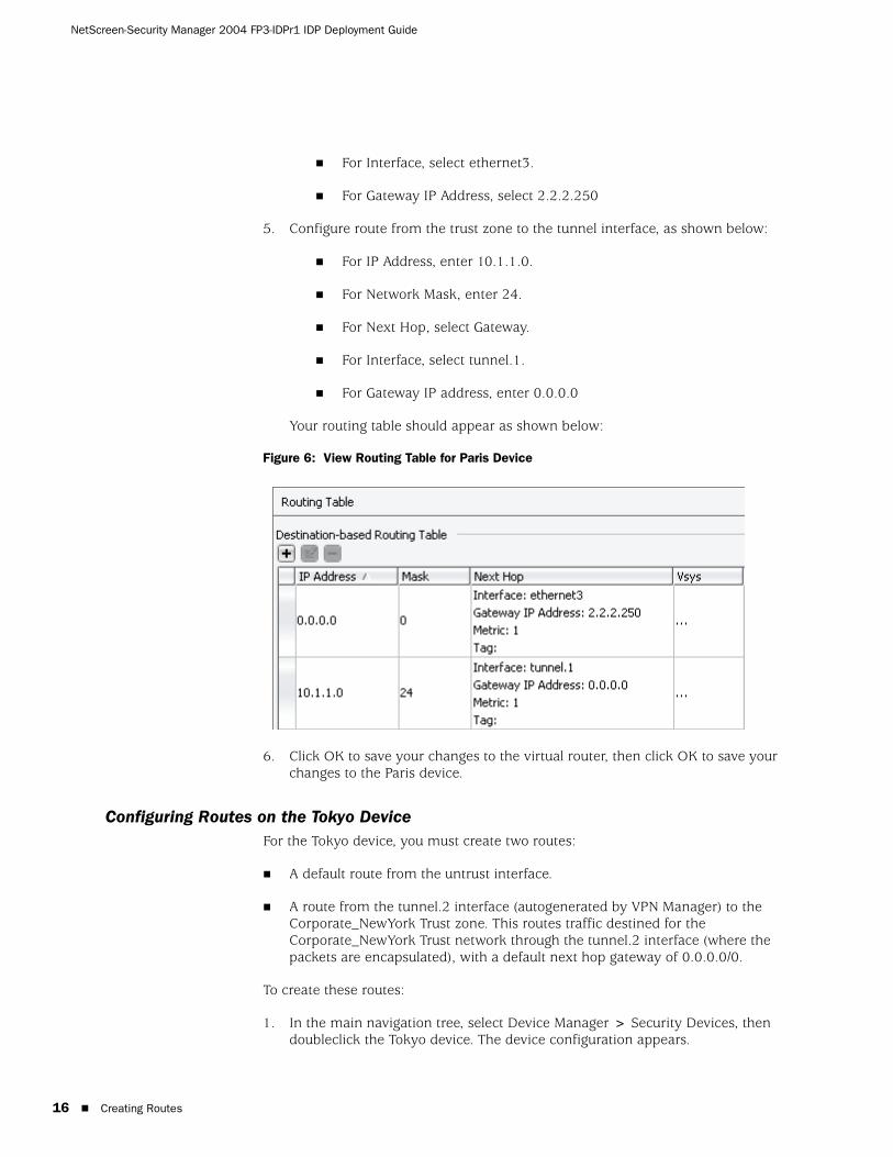
7. Confirm that your routing table appears as below:

Creating Routes 15
: Using IDP With an AutoKey IKE VPN
Figure 5: View Routing Table for Corporate VPN
8. Click OK to save your changes to the virtual router, then click OK to save your changes to the Corporate_NewYork device.
Configuring Routes on the Paris DeviceFor the Paris device, you must create two routes:
A default route from the untrust interface.
A route from the tunnel.1 interface (autogenerated by VPN Manager) to the Corporate_NewYork Trust zone. This routes traffic destined for the Corporate_NewYork Trust network through the tunnel.1 interface (where the packets are encapsulated), with a default next hop gateway of 0.0.0.0/0.
To create these routes:
1. In the main navigation tree, select Device Manager > Security Devices, then doubleclick the Paris device. The device configuration appears.
2. In the device navigation tree, select Network > Virtual Router to display the list of virtual routers on the device.
3. Doubleclick the trust-vr route. The trust-vr route dialog box appears. In the virtual router navigation tree, select Routing Table.
4. In the Destination-Based Routing Table area, click the add icon. Configure a route from the untrust interface to the gateway, as shown below, then click OK:
For IP Address, enter 0.0.0.0.
For Network Mask, enter 0.
For Next Hop, select Gateway.
NetScreen-Security Manager 2004 FP3-IDPr1 IDP Deployment Guide
16 Creating Routes
For Interface, select ethernet3.
For Gateway IP Address, select 2.2.2.250
5. Configure route from the trust zone to the tunnel interface, as shown below:
For IP Address, enter 10.1.1.0.
For Network Mask, enter 24.
For Next Hop, select Gateway.
For Interface, select tunnel.1.
For Gateway IP address, enter 0.0.0.0
Your routing table should appear as shown below:
Figure 6: View Routing Table for Paris Device
6. Click OK to save your changes to the virtual router, then click OK to save your changes to the Paris device.
Configuring Routes on the Tokyo DeviceFor the Tokyo device, you must create two routes:
A default route from the untrust interface.
A route from the tunnel.2 interface (autogenerated by VPN Manager) to the Corporate_NewYork Trust zone. This routes traffic destined for the Corporate_NewYork Trust network through the tunnel.2 interface (where the packets are encapsulated), with a default next hop gateway of 0.0.0.0/0.
To create these routes:
1. In the main navigation tree, select Device Manager > Security Devices, then doubleclick the Tokyo device. The device configuration appears.

Creating Routes 17
: Using IDP With an AutoKey IKE VPN
2. In the device navigation tree, select Network > Virtual Router to display the list of virtual routers on the device.
3. Doubleclick the trust-vr route. The trust-vr route dialog box appears. In the virtual router navigation tree, select Routing Table.
4. In the Destination-Based Routing Table area, click the add icon. Configure a route from the untrust interface to the gateway, as shown below, then click OK:
For IP Address, enter 0.0.0.0.
For Network Mask, enter 0.
For Next Hop, select Gateway.
For Interface, select ethernet3.
For Gateway IP Address, select 3.3.3.250
5. Configure route from the trust zone to the tunnel interface, as shown below:
For IP Address, enter 10.1.1.0.
For Network Mask, enter 24.
For Next Hop, select Gateway.
For Interface, select tunnel.1.
For Gateway IP Address, enter 0.0.0.0
6. Confirm that your routing table appears as below:
Figure 7: View Routing Table for Tokyo Device
7. Click OK to save your changes to the virtual router, then click OK to save your changes to the Tokyo device.

NetScreen-Security Manager 2004 FP3-IDPr1 IDP Deployment Guide
18 Creating the Security Policy
Creating the Security Policy
A Security Policy defines access to your network, specifying how external devices communicate with your internal devices and users. By default, a Security Policy denies all traffic; you must create rules to enable network traffic to pass through the firewall. For permitted traffic, you can also create IDP rules to detect (and prevent) attempted intrusion detection attempts.
In this example, you create some general firewall rules on the Corporate_NewYork, Paris, and Tokyo devices that enable them to pass traffic to each other (using the VPN) and to communicate with other external devices on Internet. You also create more specific IDP rules on the Corporate_New_York device to protect its internal network and the DMZ from attacks.
Creating & Assigning the Security Policy1. In the main navigation tree, right-click Security Policies and select New Policy.
The New Security Policy dialog box appears. Configure as detailed below:
For Name, enter Corporate.
Enter comments, if desired.
Select IDP Templates, then select the template getting_started from the template list.
2. Click OK. To view the new Security Policy, in the main navigation tree, select Security Policies > Corporate. The Corporate policy appears in the main display area.
3. Assign the Security Policy. From the menu bar, select File > Assign Policy, then select the Corporate_New York, Paris, and Tokyo devices and click OK.
By default, the getting_started template creates the new Security Policy with the Zone Rulebase and the IDP Rulebase. The template also creates default rules for each rulebase, which you can customize to fit your security requirements.
Creating Firewall RulesThe new Corporate Security Policy already includes the Zone rulebase by default, as well as two default rules (one of which is disabled). In this step, you edit these two default rules, then create two new additional rules, as detailed below:
rule 1 permits traffic to pass from the Trust zone to Untrust zone.
Rule 2 permits HTTP traffic to pass from the Untrust zone to the DMZ zone.
Rule 3 permits traffic from the WebMasters (in the Trust zone) to the DMZ zone.
NOTE: Assigning a Security Policy to a security device does not assign all rules in the policy to a device. You must explicitly configure the Install On column of each rule with the security devices you want to use the rule.

Creating the Security Policy 19
: Using IDP With an AutoKey IKE VPN
Rule 4 permits traffic from the Paris and Tokyo internal networks (in the Untrust zone) to the CorporateServers group (in the Trust zone).
For rules 2 and 4, you configure the device to pass permitted traffic to the IDP rulebase, where it can be further analyzed for attacks and dropped if necessary.
To create these firewall rules:
1. In the main navigation tree, select Security Policies > Corporate. The Corporate policy appears in the main display area. rule 1, a default rule created automatically, appears at the top of the Firewall rulebase.
2. Configure rule 1, the first default rule, to permit traffic to pass from the Trust zone to Untrust zone on the Corporate_NewYork, Paris, and Tokyo devices. Configure as shown below:
Figure 8: Firewall Rule 1
a. In the Install On column of rule 1, right-click and select Select Target. A list of managed devices appears in the Select Target Devices dialog box.
b. Select the Corporate_NewYork, Paris, and Tokyo Devices, then click OK.
3. Configure rule 2, the second default rule, to permit traffic to pass from the Untrust zone to the DMZ zone on Corporate_NewYork. Because this rule controls traffic from the external network to your WebServers, leave the default IDP option as Enabled. Configure as shown below:
Figure 9: Firewall Rule 2
c. In the From Zone column of rule 2, right-click and select Select Zone. In the Select Zone dialog box, select the Untrust zone then click OK.
d. In the To Zone column of rule 2, right-click and select Select Zone. In the Select Zone dialog box, select the Trust zone then click OK.
e. In the Destination column of rule 2, right-click and select Add Address. In the Select Destination Address dialog box, select the WebServers address group, then click OK.
f. In the Install On column of rule 2, right-click and select Select Target. A list of managed devices appears in the Select Target Devices dialog box. Select the Corporate_New_York device.
4. Configure a new rule to permit traffic from the WebMasters (in the Trust zone) to the DMZ zone on Corporate_New_York. Because this rule controls internal traffic, enable IDP. Click the Add icon and select Add Rule; a new default rule, rule 3, appears below rule 2. Configure as shown below:

NetScreen-Security Manager 2004 FP3-IDPr1 IDP Deployment Guide
20 Creating the Security Policy
Figure 10: Firewall Rule 3
a. In the Source column of rule 3, right-click and select Add Address. In the Select Source Address dialog box, select the WebMasters address group, then click OK.
b. In the To Zone column of rule 3, right-click and select Select Zone. In the Select Zone dialog box, select the DMZ zone then click OK.
c. In the Destination column of rule 3, right-click and select Add Address. In the Select Destination Address dialog box, select the WebServers address group, then click OK.
d. In the Action column of rule 3, right-click and select Permit.
e. In the Install On column of rule 3, right-click and select Select Target. A list of managed devices appears in the Select Target Devices dialog box. Select the Corporate_NewYork device.
f. In the Rule Options column of rule 3, right-click and select DI Profile/Enable IDP. In the IDP Options area, select Enabled, then configure the Enabled mode as Inline. Click OK.
5. Configure a new rule to permit traffic from the Paris and Tokyo trusted network to the Corporate Servers in the Corporate_NewYork trusted network. Because this rule controls inbound traffic through the VPN, you also enable IDP. Click the Add icon and select Add Rule; a new default rule, rule 4, appears below rule 3. Configure as shown below:
Figure 11: Firewall Rule 4
a. In the From Zone column of rule 4, right-click and select Select Zone. In the Select Zone dialog box, select the Untrust zone then click OK.
b. In the Source column of rule 4, right-click and select Add Address. In the Select Source Address dialog box, select the Paris Trust and Tokyo Trust network address objects, then click OK.
c. In the To Zone column of rule 4, right-click and select Select Zone. In the Select Zone dialog box, select the Trust zone then click OK.
d. In the Destination column of rule 4, right-click and select Add Address. In the Select Destination Address dialog box, select the CorporateServers address group, then click OK.
e. In the Action column of rule 4, right-click and select Permit.
f. In the Install On column of rule 4, right-click and select Select Target. A list of managed devices appears in the Select Target Devices dialog box. Select the Corporate_NewYork device.
Creating the Security Policy 21
: Using IDP With an AutoKey IKE VPN
g. In the Rule Options column of rule 4, right-click and select DI Profile/Enable IDP. In the IDP Options area, select Enabled, then configure the Enabled mode as Inline. Click OK.
Creating IDP RulesIn this step, you configure IDP rules (created by default when using the getting_started template). These rules monitor traffic from the external network to your WebServers and inbound traffic from the VPN to the New York trust zone. The template uses a separate rule for each major protocol, making it easy for you to fine-tune the Security Policy to your network traffic.
Your goal in creating these IDP rules is to:
Protect your Web servers from external attack.
Protect your Mail and FTP corporate servers against attacks from the Paris and/or Tokyo trusted networks.
Protect the Corporate_New York trusted network from trojans, viruses, worms, or other exploit attempts that might have infected the Paris and/or Tokyo trusted networks.
In the Corporate Security Policy, click the IDP tab to display the IDP rulebase, then configure the following IDP rules:
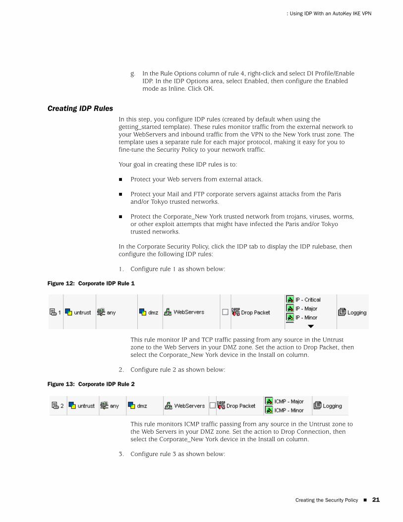
1. Configure rule 1 as shown below:
Figure 12: Corporate IDP Rule 1
This rule monitor IP and TCP traffic passing from any source in the Untrust zone to the Web Servers in your DMZ zone. Set the action to Drop Packet, then select the Corporate_New York device in the Install on column.
2. Configure rule 2 as shown below:
Figure 13: Corporate IDP Rule 2
This rule monitors ICMP traffic passing from any source in the Untrust zone to the Web Servers in your DMZ zone. Set the action to Drop Connection, then select the Corporate_New York device in the Install on column.
3. Configure rule 3 as shown below:

NetScreen-Security Manager 2004 FP3-IDPr1 IDP Deployment Guide
22 Creating the Security Policy
Figure 14: Corporate IDP Rule 3
This rule monitors HTTP traffic passing from the Untrust zone to the Web Servers in your DMZ zone. Set the action to Drop Packet, then select the Corporate_New York device in the Install on column.
4. Configure rule 4 as shown below:
Figure 15: Corporate IDP Rule 4
This rule monitors SMTP traffic passing from the Paris and Tokyo Trust networks in the Untrust zone to the Mail server in the Trust zone. However, because the attack category SMTP-Minor contains attacks that detect email attachments (both malicious and benign), you remove that attack group from the rule.
a. Set the action to Drop Connection.
b. In the Attack column, right-click and select Select Attacks. The Attack dialog box appears. In the right column, select SMTP-Minor, then click Remove. Click OK to save your changes.
c. In the Install On column, right-click and select the Corporate_New York device.
5. Configure rule 5 as shown below:
Figure 16: Corporate IDP Rule 5
This rule monitors DNS traffic passing from the Paris and Tokyo Trust networks in the Untrust zone to your FTP server (which is running DNS) in the Trust zone. Set the action to Drop Connection, then select the Corporate_New York device in the Install on column.
6. Configure rule 6 as shown below:
Figure 17: Corporate IDP Rule 6

Creating the Security Policy 23
: Using IDP With an AutoKey IKE VPN
This rule monitors FTP traffic passing from the Paris and Tokyo Trust networks in the Untrust zone to your FTP server in the Trust zone. Set the action to Drop Connection, then select the Corporate_New York device in the Install on column.
7. Configure rule 7 as shown below:
Figure 18: Corporate IDP Rule 7
This rule monitors POP3 traffic passing from the Paris and Tokyo Trust networks in the Untrust zone to the Mail server in the Trust zone. However, because the attack category POP3-Minor contains attacks that detect email attachments (both malicious and benign), you remove that attack group from the rule.
a. Set the action to Drop Connection.
b. In the Attack column, right-click and select Select Attacks. The Attack dialog box appears. In the right column, select POP3-Minor, then click Remove. Click OK to save your changes.
c. In the Install On column, right-click and select the Corporate_New York device.
8. Configure rule 8 as shown below:
Figure 19: Corporate IDP Rule 8
This rule monitors IMAP traffic passing from any source in the Untrust zone to any destination in the Trust zone. Set the action to Drop Connection, then select the Corporate_New York security device in the Install on column.
9. Configure rule 9 as shown below:
Figure 20: Corporate IDP Rule 9

NetScreen-Security Manager 2004 FP3-IDPr1 IDP Deployment Guide
24 Creating the Security Policy
This rule monitors worms, viruses, and trojans passing from the Untrust zone to your Corporate Servers (in the Trust zone) and to your Web Servers (in the DMZ zone). However, because the attack category Viruses-Minor contains attacks that detect email attachments (both malicious and benign), you remove that attack group from the rule.
a. Set the action to Drop Connection.
b. In the Attack column, right-click and select Select Attacks. The Attack dialog box appears. In the right column, select Viruses-Minor, then click Remove. Click OK to save your changes.
c. In the Install On column, right-click and select the Corporate_New York device.
After you have created the IDP rules, save the Security Policy, validate it, then install the policy on your managed devices.
NOTE: When using the IDP rules for an IDP-capable device that controls traffic between an external and internal mail server, do not use the Virus attack groups unless you are actively filtering for viruses on the external mail server.
When an external mail server is not protected by an IDP-capable device or does not filter for viruses in email attachments, the server might forward an infected email message to the internal mail server, where the message becomes part of the mail queue. If a Virus attack object detects a virus in the message in the mail queue and the security device drops the connection. the mail client simply reconnects and attempts to download the same email again, causing an infinite loop. The “bad” email” is never cleared from the queue, and the user for which the email is intended cannot receive emails.

25
Using the ISG 2000 as a Dedicated IDP
This guide details how to use NetScreen-Security Manager to configure a secure network using the ISG 2000 security device running ScreenOS 5.0 IDP. Juniper Networks NetScreen-Security Manager 2004 is a software application that centralizes control and management of your Juniper Networks security devices. The ISG 2000 running ScreenOS5.0 IDP security device integrates firewall, virtual private network, and intrusion detection prevention technology in a single, powerful security device.
In this example, you deploy an ISG 2000 with IDP as a dedicated IDP security device to protect critical Web servers in the DMZ zone of the corporate network.
For the perimeter firewall, you use a NetScreen-208, on which you configure a Security Policy that contains Zone-based rules to permit external access to the Web servers and for standard internal access between the DMZ and Trust zones.
For the DMZ firewall, you use the ISG 2000 with IDP. All traffic bound for the Web Servers passes through this device, on which you configure a simple firewall rule to pass all traffic to the IDP rulebase where IDP rules protect the Web Servers from external attack.
NOTE: For details on the concepts and processes used in this document, refer to the NetScreen-Security Manager 2004 FP3-IDPr1 Administrator’s Guide and Online Help.
NetScreen-Security Manager 2004 FP3-IDPr1 IDP Deployment Guide
26
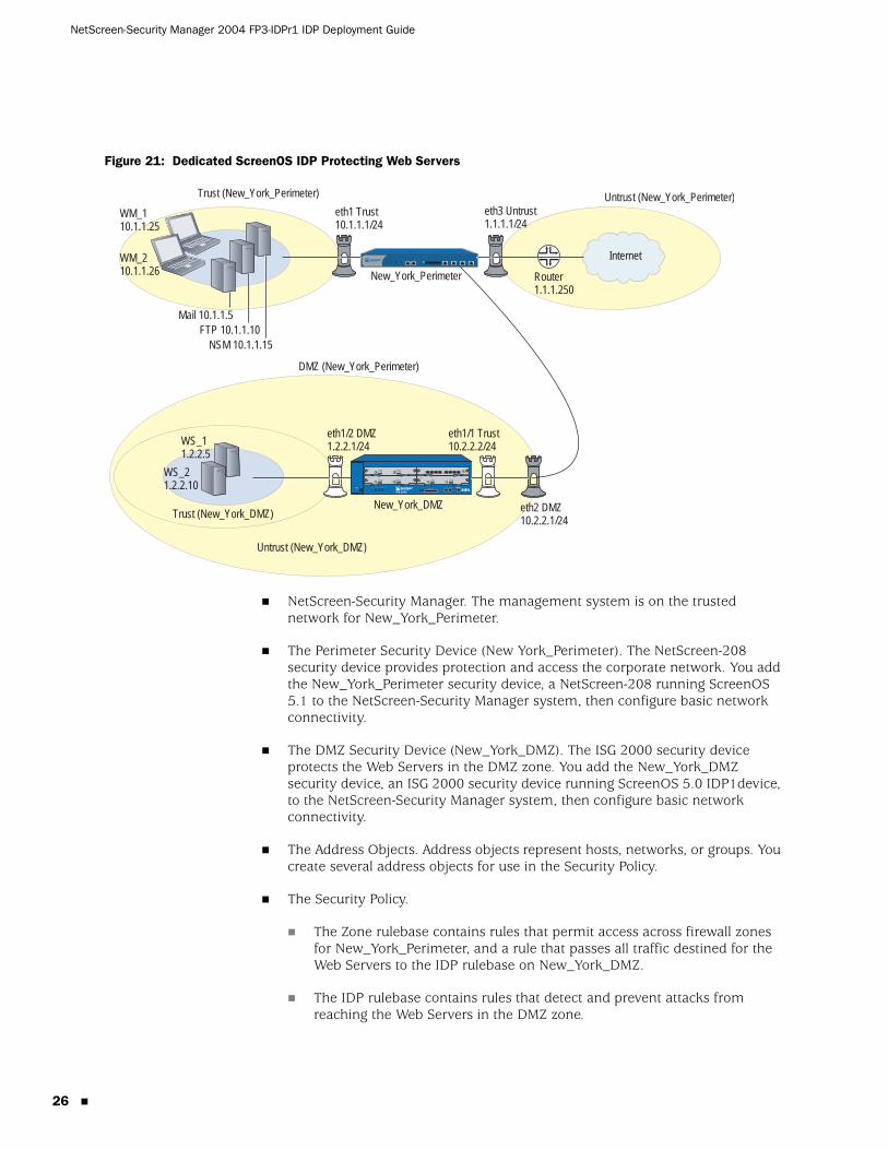
Figure 21: Dedicated ScreenOS IDP Protecting Web Servers
NetScreen-Security Manager. The management system is on the trusted network for New_York_Perimeter.
The Perimeter Security Device (New York_Perimeter). The NetScreen-208 security device provides protection and access the corporate network. You add the New_York_Perimeter security device, a NetScreen-208 running ScreenOS 5.1 to the NetScreen-Security Manager system, then configure basic network connectivity.
The DMZ Security Device (New_York_DMZ). The ISG 2000 security device protects the Web Servers in the DMZ zone. You add the New_York_DMZ security device, an ISG 2000 security device running ScreenOS 5.0 IDP1device, to the NetScreen-Security Manager system, then configure basic network connectivity.
The Address Objects. Address objects represent hosts, networks, or groups. You create several address objects for use in the Security Policy.
The Security Policy.
The Zone rulebase contains rules that permit access across firewall zones for New_York_Perimeter, and a rule that passes all traffic destined for the Web Servers to the IDP rulebase on New_York_DMZ.
The IDP rulebase contains rules that detect and prevent attacks from reaching the Web Servers in the DMZ zone.
HA
FLASH
PWR
FAN
ALARM
MOD1
TEMP
MOD2
STATUS
MOD3 ISG 2000
Internet
eth3 Untrust1.1.1.1/24
New_York_Perimeter
New_York_DMZ
Router1.1.1.250
eth2 DMZ10.2.2.1/24
eth1/1 Trust10.2.2.2/24
eth1/2 DMZ1.2.2.1/24
eth1 Trust10.1.1.1/24
Mail 10.1.1.5FTP 10.1.1.10
NSM 10.1.1.15
DMZ (New_York_Perimeter)
Untrust (New_York_DMZ)
Untrust (New_York_Perimeter)Trust (New_York_Perimeter)
Trust (New_York_DMZ)
WS_2 1.2.2.10
WS_1 1.2.2.5
WM_110.1.1.25
WM_210.1.1.26

Configuring the Perimeter Device 27
: Using the ISG 2000 as a Dedicated IDP
Configuring the Perimeter Device
Add and configure a perimeter security device with the following settings:
For Device Name, enter New_York_Perimeter.
For Device Color, select Red.
For Device IP address, enter 10.1.1.0/24 (this is the Trust interface).
Configure ethernet1 in the Trust zone, with IP address 10.1.1.0/24
Configure ethernet2 in the DMZ zone, with IP address 10.2.2.1/24.
Configure ethernet3 in the Untrust zone, with IP address 1.1.1.1/24
Configure a default route from the DMZ interface on the New_York_Perimeter device to the IP address of the Trust interface on the New_York_DMZ device.
Configure DNS to use primary server 10.1.1.11 and secondary server 10.1.1.12.
Configuring the ISG 2000 Security Device
To add the ISG 2000 with ScreenOS IDP device, you must first stage the physical device by connecting it to your network, assigning an IP address to the untrust interface, ensuring that the device has network connectivity, and enabling telnet or ssh.
After you stage the device, you can use the device connection information (IP address, etc.) and device admin name and password to add the device to the management system. During the add process, the management system connects to the device and imports information about the device configuration. This always-on connection is secured using Secure Server Protocol (SSP), a proprietary encryption method.
Staging the ISG 2000 FW/VPN/IDP DeviceTo stage the ISG 2000 with ScreenOS IDP, connect to the device using a vt100 terminal emulator program through the console port, then configure the following basic device settings:
Set the admin name to Nicolas
Set the admin password to Wu82iE9
Enable SSH using the WebUI or the console command set ssh enable.
Configure ethernet1/1 in the Trust zone. Assign ethernet1/1 the IP address 10.2.2.2, and enable the following services: ping, telnet, web, and ssh.
NOTE: All passwords handled by NetScreen-Security Manager are case-sensitive.

NetScreen-Security Manager 2004 FP3-IDPr1 IDP Deployment Guide
28 Configuring the ISG 2000 Security Device
Next, connect the device to your network, ensuring that ethernet1/1 has network connectivity (to add the device, the management system must be able to access the ethernet port).
Adding the ISG 2000 FW/VPN/IDP Device to NetScreen-Security ManagerTo add the ISG 2000 with ScreenOS IDP device to NetScreen-Security Manager, first use the Add Device wizard to import the device configuration, then verify the imported configuration.
1. Open the NetScreen-Security Manager UI. In the main navigation tree, select Device Manager > Security Devices.
2. Click the Add icon and select Device. The Add Device wizard appears. Configure the following:
For Name, enter New_York_DMZ.
For Color, select green.
Select Device is Reachable (default).
3. Click Next to display the Specify Connection Settings dialog box. Configure the following:
For IP Address, enter 10.2.2.2.
For Device Admin Username, enter Nicolas.
For Password, enter Wu82iE9.
For connection method, select SSH Version 2.
For port number, enter 22.
4. Click Next to display The Verify Device Authenticity dialog box. The device wizard displays the RSA Key FingerPrint information; to prevent man-in-the-middle attacks, you should verify the fingerprint using an out-of-band method.
5. Click Next. The wizard displays the autodetected device information. Verify that the device type, ScreenOS version, and the device serial number are correct, then click Finish to complete the Add Device wizard. The Corporate_NewYork device appears in the Device Manager list.
6. To check the device configuration status, mouseover the device in Device Manager (you can also check configuration status in Device Monitor):
Before the device connects, the status displays Waiting for 1st connect, indicating that the management system is waiting for the device to connect. (This event occurs very quickly and might not display.)
NOTE: All passwords handled by NetScreen-Security Manager are case-sensitive.
Configuring the ISG 2000 Security Device 29
: Using the ISG 2000 as a Dedicated IDP
After the device connects, the status displays Import Needed, indicating that the device has connected but the management system has not imported the device configuration yet.
7. Import the device configuration by right-clicking the device and selecting Import Device. The Job Information box appears and displays the job type and status for the import; when the job status displays successful completion, click Close.
8. After the import is complete, double-click the device in Device Manager to view the imported configuration. To check the device configuration status, mouseover the device in Device Manager (you can also check configuration status in Device Monitor). The device status displays as Managed, indicating that the device has connected and the management system has successfully imported the device configuration.
Configuring ISG 2000 with ScreenOS IDP1. Configure the DMZ interface for ethernet1/2.
a. In the main navigation tree, select Device Manager > Security Devices, then doubleclick the New_York_DMZ device to open the device configuration.
b. In the device navigation tree, select Network > Interface, then doubleclick ethernet1/2. The General Properties screen appears. Configure the following:
For IP address, enter 1.2.2.1.
For Netmask, enter 24.
Clear Manageable (clear the checkbox).
2. Configure the Trust interface for ethernet 1/1:
a. In the device navigation tree, select Network > Interface, then double-click ethernet1/1. The General Properties screen appears. Configure the following:
For IP address, enter 10.2.2.2/24
For Netmask, enter 24.
In the interface navigation tree, select Service Options. Select ping, telnet, ssh, and web, then click OK to save your changes.
b. Click OK to save your changes.
3. Configure DNS:
a. In the device navigation tree, select Network > DNS > Settings.
b. Configure the DNS settings:

NetScreen-Security Manager 2004 FP3-IDPr1 IDP Deployment Guide
30 Creating Address Objects
For Primary DNS Server IP, enter 10.1.1.11.
For Primary DNS Server IP, enter 10.1.1.12.
For DNS Refresh Schedule, select Refresh Daily. Leave the refresh defaults.
c. Click OK to save your changes.
4. Configure a default route from the Trust interface on New_York_DMZ to the DMZ interface on New_York_Perimeter:
d. In the device navigation tree, select Network > Virtual Router to display the list of virtual routers on the device.
e. Doubleclick the trust-vr route. The trust-vr route dialog box appears. In the virtual router navigation tree, select Routing Table.
f. In the Destination-Based Routing Table area, click the add icon. Configure a route from the trust interface to the gateway (the DMZ interface on New_York_Perimeter), as shown below, then click OK:
For IP Address, enter 0.0.0.0.
For Network Mask, enter 0.
For Next Hop, select Gateway.
For Interface, select ethernet1/1.
For Gateway IP Address, select 10.2.2.1.
Creating Address Objects
If you have previously created the following objects when using the first deployment example “Using ScreenOS IDP with an AutoKey IKE VPN”, you do not need to recreate them.
1. Add the WebServer1 host Address Object.
a. In the main navigation tree, select Object Manager > Address Object.
b. Click the Add icon and select Host.
c. Configure the following:
For Name, enter WS_1.
For Color, select cyan.
For IP address, enter 1.2.2.5.
d. Click OK to save your changes.

Creating Address Objects 31
: Using the ISG 2000 as a Dedicated IDP
2. Add the WebServer2 host Address Object.
a. In Address Objects, click the Add icon and select host.
b. Configure the following:
For Name, enter WS_2.
For Color, select magenta.
For IP address, enter 1.2.2.10.
c. Click OK to save your changes.
3. Add the WebMaster1 host Address Object.
a. In Address Objects, click the Add icon and select host.
b. Configure the following:
For Name, enter WM_1.
For Color, select orange.
For IP address, enter 10.1.1.25.
c. Click OK to save your changes.
4. Add the WebMaster2 host Address Object.
a. In Address Objects, click the Add icon and select host.
b. Configure the following:
For Name, enter WM_2.
For Color, select pink.
For IP address, enter 10.1.1.26.
c. Click OK to save your changes.
5. Add the Mail host Address Object.
a. In Address Objects, click the Add icon and select host.
b. Configure the following:
For Name, enter Mail.
For Color, select blue.
For IP address, enter 10.1.1.5.
c. Click OK to save your changes.

NetScreen-Security Manager 2004 FP3-IDPr1 IDP Deployment Guide
32 Creating the Security Policy
6. Add the FTP host Address Object.
a. In Address Objects, click the Add icon and select host.
b. Configure the following:
For Name, enter FTP.
For Color, select black.
For IP address, enter 10.1.1.10.
For alternate IP addresses, enter 10.1.1.11 and 10.1.1.12, which are running DNS services.
c. Click OK to save your changes.
7. Add three Address Groups:
Add a group named “WebServers” that contains WS_1 and WS_2.
Add a group named “WebMasters” that contains WM_1 and WM_2.
Add a group named “CorporateServers” that contains Mail, FTP, and INT.
Creating the Security Policy
A Security Policy defines access to your network, specifying how external devices communicate with your internal devices and users. By default, a Security Policy denies all traffic; you must create rules to enable network traffic to pass through the firewall. For permitted traffic, you can also create IDP rules to detect (and prevent) attempted intrusion detection attempts.
For the New_York_Perimeter, you create firewall rules that enable the trusted network to communicate with the Internet, the Internet to communicate with the Web servers in the DMZ zone, and the Webmasters in the Trust zone to communicate with the WebServers in the DMZ zone.
For the New_York_DMZ, you create a single firewall rule that passes traffic to the IDP rulebase, where you create specific IDP rules to protect the Web servers from external attack.
Creating & Assigning the Security Policy1. In the main navigation tree, right-click Security Policies and select New Policy.
The New Security Policy dialog box appears. Configure as detailed below:
For Name, enter New_York_Dedicated.
Enter comments, if desired.
Select IDP Templates, then select the template dmz_services from the template list.

Creating the Security Policy 33
: Using the ISG 2000 as a Dedicated IDP
2. Click OK. To view the new Security Policy, in the main navigation tree, select Security Policies > New_York_Dedicated. The security policy appears in the main display area.
3. Assign the Security Policy. From the menu bar, select File > Assign Policy, then select the New_York_Perimeter and New_York_DMZ devices and click OK.
By default, the dmz_services template creates the new Security Policy with the Zone Rulebase and the IDP Rulebase. The template also creates default rules for each rulebase, which you can customize to fit your security requirements.
Creating Firewall RulesThe new Security Policy already includes the Zone rulebase by default, as well as two default rules (one of which is disabled). In this step, you edit these two default rules, then create three new additional rules, as detailed below:
Rule 1 permits all traffic from the Trust zone to the DMZ zone on the New_York_DMZ device. This rule also passes all traffic to the IDP rulebase, where the traffic can be further analyzed for attacks and dropped if necessary.
Rule 2 permits all traffic from the DMZ zone to the Trust zone on the New_York_DMZ device.
Rule 3 permits traffic to pass from the Trust zone to Untrust zone on the New_York_Perimeter device.
Rule 4 permits all traffic destined for the WebServers to pass from the Untrust zone to the DMZ zone on the New_York_Perimeter device.
Rule 5 permits traffic from the WebMasters (in the Trust zone) to the DMZ zone on the New_York_Perimeter device.
To create these firewall rules:
1. In the main navigation tree, select Security Policies > New_York_Dedicated. The security policy appears in the main display area. Rule 1, a default rule created automatically, appears at the top of the zone rulebase.
2. Configure Rule 1, the first default rule, to permit traffic from the Trust zone to the DMZ zone on the New_York_DMZ device. Because this rule handles inbound traffic from the WebServers, you leave IDP enabled (IDP is enabled by default when using an IDP template). Configure as shown below:
NOTE: Assigning a Security Policy to a security device does not assign all rules in the policy to a device. You must explicitly configure the Install On column of each rule with the security devices you want to use the rule.

NetScreen-Security Manager 2004 FP3-IDPr1 IDP Deployment Guide
34 Creating the Security Policy
Figure 22: Dedicated Zone Rule 1
d. In the To Zone column of rule 1, right-click and select Select Zone. In the Select Zone dialog box, select the DMZ zone then click OK.
e. In the Install On column of rule 1, right-click and select Select Target. A list of managed devices appears in the Select Target Devices dialog box. Select the New_York_DMZ device, then click OK.
3. Configure Rule 2, the second default rule, to permit traffic from the DMZ zone to the Trust zone on the New_York_DMZ device. Because this rule handles outbound traffic from the WebServers, you leave IDP enabled (IDP is enabled by default when using an IDP template). Configure as shown below:
Figure 23: Dedicated Zone Rule 2
a. In the rule number column of rule 2, right-click and select Disable. This clears the disable option, enabling the rule and removing the gray diagonal lines from the rule columns.
b. In the From Zone column of the rule 2, right-click and Select Zone. In the Select Zone dialog box, select the DMZ zone then click OK.
c. In the Install On column of rule 2, right-click and select Select Target. A list of managed devices appears in the Select Target Devices dialog box. Select the New_York_DMZ device, then click OK.
4. Configure a new rule (rule 3) to permit traffic from the Trust zone to Untrust zone on the New_York_Perimeter device. Click the Add icon and select Add Rule; a new default rule, rule 3, appears below rule 2. Configure as shown below:
Figure 24: Dedicated Zone Rule 3
a. In the Action column of rule 3, right-click and select Permit.
b. In the Install On column of rule 3, right-click and select Select Target. A list of managed devices appears in the Select Target Devices dialog box. Select the New_York_Perimeter device, then click OK.
5. Configure a new rule (rule 4) to permit all traffic destined for the WebServers to pass from the Untrust zone to the DMZ zone on New_York_Perimeter. Click the Add icon and select Add Rule; a new default rule, rule 4, appears below rule 3. Configure as shown below:

Creating the Security Policy 35
: Using the ISG 2000 as a Dedicated IDP
Figure 25: Dedicated Zone Rule 4
a. In the From Zone column of rule 4, right-click and select Select Zone. In the Select Zone dialog box, select the Untrust zone then click OK.
b. In the To Zone column of rule 4, right-click and select Select Zone. In the Select Zone dialog box, select the DMZ zone then click OK.
c. In the Destination column of rule 4, right-click and select Add Address. In the Select Destination Address dialog box, select the WebServers address group, then click OK.
d. In the Action column of rule 4, right-click and select Permit.
e. In the Install On column of rule 4, right-click and select Select Target. A list of managed devices appears in the Select Target Devices dialog box. Select the New_York_Perimeter device.
6. Configure a new rule (rule 5) to permit traffic from the WebMasters (in the Trust zone) to the DMZ zone on New_York_Perimeter. Click the Add icon and select Add Rule; a new default rule, rule 5, appears below rule 4. Configure as shown below:
Figure 26: Dedicated Zone Rule 5
a. In the Source column of rule 5, right-click and select Add Address. In the Select Source Address dialog box, select the WebMasters address group, then click OK.
b. In the To Zone column of rule 5, right-click and select Select Zone. In the Select Zone dialog box, select the DMZ zone then click OK.
c. In the Destination column of rule 5, right-click and select Add Address. In the Select Destination Address dialog box, select the WebServers address group, then click OK.
d. In the Action column of rule 5, right-click and select Permit.
e. In the Install On column of rule 5, right-click and select Select Target. A list of managed devices appears in the Select Target Devices dialog box. Select the New_York_Perimeter device.
Creating IDP RulesIn this step, you configure IDP rules (created by default when using the dmz_services template). These rules monitor traffic from the external network to your WebServers. Your goal in creating these IDP rules is to protect your Web servers from external attack.

NetScreen-Security Manager 2004 FP3-IDPr1 IDP Deployment Guide
36 Creating the Security Policy
In the Dedicated Security Policy, click the IDP tab to display the IDP rulebase, then configure the following IDP rules as shown below:
Figure 27: Dedicated IDP Rulebase
1. By default, rule 1 drops traffic that should not occur on a clean network, and hardens the security modules against evasion attempts. To configure this rule for your network, in the Install on column, select the New_York_DMZ device.
2. Be default, rule 2 drops and logs all DNS and DHCP traffic that contains critical severity attacks. To configure this rule for your network, in the Install on column, select the New_York_DMZ device.
3. By default, rule 3 drops critical and high severity attacks against common DMZ services and logs alarms. To configure this rule for your network, in the Install on column, select the New_York_DMZ device.
4. By default, rule 4 logs medium severity attacks and IDS evasion attempts. To configure this rule for your network, in the Install on column, select the New_York_DMZ device.

Creating the Security Policy 37
: Using the ISG 2000 as a Dedicated IDP
5. By default, rule 5 logs low severity attacks; this rule is disabled because some networks contain many low severity events that result in unnecessary logs. To configure this rule for your network:
a. In the rule number column of rule 5, right-click and select Disable. This clears the disable option, enabling the rule and removing the gray diagonal lines from the rule columns.
b. In the Install on column of rule 5, select the New_York_DMZ device.
6. By default, rule 6 rule logs informational events; this rule is disabled because some networks contain many information severity events that result in unnecessary logs. Informational signatures do not necessarily detect attacks, but can provide additional data about your network traffic. To configure this rule for your network:
a. In the rule number column of rule 6, right-click and select Disable. This clears the disable option, enabling the rule and removing the gray diagonal lines from the rule columns.
b. In the Install on column of rule 6, select the New_York_DMZ device.
After you have configured the IDP rules, save the Security Policy, validate it, then install the policy on the New_York_DMZ and New_York_Perimeter security devices.

NetScreen-Security Manager 2004 FP3-IDPr1 IDP Deployment Guide
38 Creating the Security Policy