ihi international holdings ltd. international holdings ltd. this is an example of ihi’s panelized...
TRANSCRIPT

IHI INTERNATIONAL HOLDINGS LTD.
THIS IS AN EXAMPLE OF IHI’s PANELIZED DESIGN & MANUFACTURING PROCESS OF AN IHI BUILDINGMANUFACTURING PROCESS OF AN IHI BUILDING
FEATURING A HOUSE ON A HILLCOMPLETED IN NOVEMBER 2007COMPLETED IN NOVEMBER 2007

SOFTWARE PROCESS
The software process involves the input of standard architectural drawings that are electronically analysed and transformed into Hi-Tech System panels. The process is as follows:follows:
First, floor plans and elevations are either received in CAD format or are scanned and converted to electronic plans. The software then proceeds through a number of iterations to determine the optimal panel layout and configuration. As there are no moulds or standard
l h bl d l l h fpanel sizes, the computer is able to determine optimal panels without restrictions of size and shape. Therefore, iteration may yield a panel layout where no two panels are alike. From the first series of iterations, a three-dimensional model is developed which shows how the building will look and how the panels will come together. At this point, the developer d d h f f h b d h h h b lddecides on the type of finishing to be used. The program can then cost out the building and offer a series of price scenarios, which show various finishing options. With the choice of final finishing, the program then determines critical loading factors.
A second computer program is then used for determining structural analysis. Typically, for a 280m2 (3,000 sq. foot) home, seventy or so iterations are developed, all of which are structurally sound. The program then seeks out the optimal structure based on weight, cost, and strength components and the final panel boundaries are set. After optimisation, the program determines stress contours on each panel and develops stress contours on the concrete.

SOFTWARE PROCESS (cont..)
Redundant concrete (concrete which serves no structural purpose) can represent up to Redundant concrete (concrete which serves no structural purpose) can represent up to 65% of total panel volume. Based on the stress contours, the program eliminates all redundant concrete. With the elimination of 60-65% dead weight, the remaining 35-40% maintains a large latent structural load resistance, especially with respect to dynamic loading (dynamic loading which is stress caused by the movement of thedynamic loading (dynamic loading which is stress caused by the movement of the building, is particularly important during an earthquake). When concrete is removed from a panel, the program automatically replaces it with rigid insulation, reducing weight and cost, but increasing thermal and sound baffling properties. In addition to the structural capabilities a final check of stress points is undertaken to assure the soundness ofcapabilities, a final check of stress points is undertaken to assure the soundness of design.
When complete, the program stores the precise instructions needed for the computer-aided manufacturing process.
This software represents one of the most important features of IHI technology. The software continues to be developed to reflect newly created solutions in product and production process.

MANUFACTURING FLOW
Manufacturing Flow The panel manufacturing process can be divided into three distinct operations: Preparation and cutting of structural steel and rigid foam unit Preparation of panel structural components (drill, punch, robotic and
automated welding), integrating with foam and applying concrete and/orstucco)Finishing of panels to specifications (flooring roofing utilities etc ) Finishing of panels to specifications (flooring, roofing, utilities, etc.)
1) Preparation and Cutting: Once the software has determined the optimal panel configuration and
t t l l t th i f ti i t f d t th t id dstructural layout, the information is transferred to the computer-aidedmanufacturing units in the plant. To maintain efficiency, all material is shapedand prepared prior to its entry into the production line. This includes cutting,drilling, shaping, punching and welding all steel components. It also includes
tti f th t t l t l d i id f i C tti i l thcutting of the structural steel and rigid foam pieces. Cutting involves a three-dimensional contouring of the foam as prescribed by the software. In effect,the foam acts as an interior form and displaces redundant concrete.
After preparation, material is sorted into the correct assemblies and taken by lift truck to be stored near the area in the production area where it is to be used.

2) Structural Components, Foam Integration, Concrete Application:
2) Structural Components, Foam Integration, Concrete Application:
Structural steel is cut automatically to length and automated templates are used to either punch or drill holes where needed. Joint pins are pressed into place andeither punch or drill holes where needed. Joint pins are pressed into place and joints are welded or connected into place. Hooks for holding steel mesh are welded to structural tubes, as are saddles. From a template, welded wire mesh and stucco mesh (if an exterior panel) is cut to size.
The pre-formed foam core is laid down on the mesh and building paper and structural members are placed on top. With the aid of a hydraulic/pneumatic jig, the frame is assembled and electrical boxes are put in place as required. The structural members are then tensioned with cables and turnbucklesstructural members are then tensioned with cables and turnbuckles.
Concrete is then poured on the panel and troweled smooth. After setting, the panel is turned over and a protective coat is applied on both concrete surfaces.

3) Finishing) g
3) Finishing
Panels that are custom finished are completed in a similar fashion to conventional construction.This includes roofing, flooring, door and window installation, and bathrooms/kitchens ifrequired. However, if above are done in a controlled environment in the factory, the IHIsystem will gain further advantages. In the future, the company will start working onimplementing a process to begin automating the finishing process.
Factory window installation in panels provides the purchaser with a series of benefits. First,Factory window installation in panels provides the purchaser with a series of benefits. First,because there is no window frame (the frame is part of the structural steel frame of the panel),windows are purchased frameless and as such are about 30% cheaper. Second, because thesteel window housing is an integral part of the panel, windows are much more secured. This isvery important in regions subject to hurricane-force winds. In a hurricane, the windows (andvery important in regions subject to hurricane force winds. In a hurricane, the windows (andoften the roof) are generally the first to be damaged - not by debris, but because they areblown out of their frame. Once a window is gone, there is an increased vacuum effect withinthe house causing more windows to go and generating more damage.

ARCHITECTURAL DESIGN DRAWINGS BY IHI PLANNING Ltd.

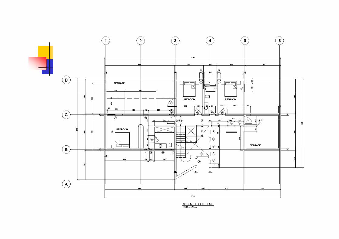


3D VIEW OF THE HOUSE ON A HILL PREPARED BY IHI PLANNING LTD.
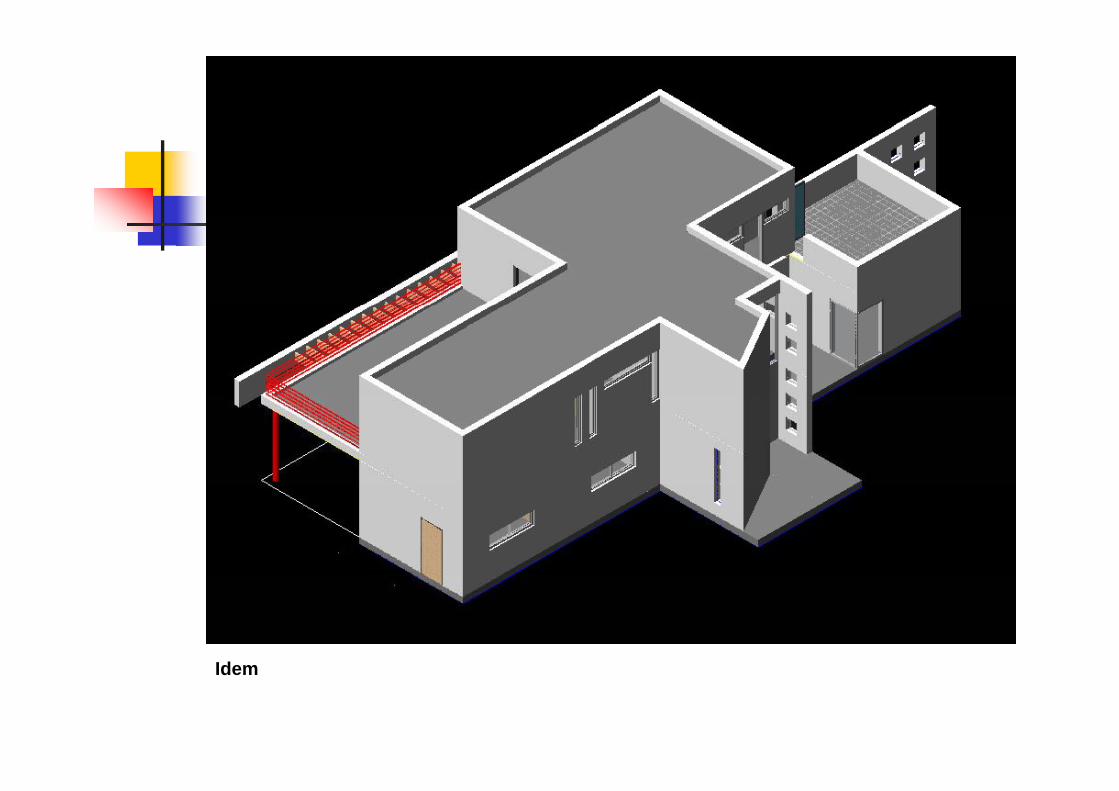
IdIdem

THIS SLIDE SHOWS CAST-IN PLACE FOUNDATIONS (DARK) AND THE IHI PANELS CONNECTED TO THE FOUNDATIONS BY MEANS OF STEEL EMBEDMENT'S SUPPLIED BY IHI.

THIS IMAGE SHOWS THE OPTIMUM IHI STRUCTURAL PANEL DESIGN WITH CONNECTION STEEL BRACKETS SHOWN ON THE ROOF PANELS. IHI PRODUCES A SET OF DETAILED SHOP DRAWINGS FOR EACH INDIVIDUAL IHI PANEL TO BE APPROVED BY THE CLIENT’S ENGINEERS AND ARCHITECT PRIOR TO MANUFACTURING.
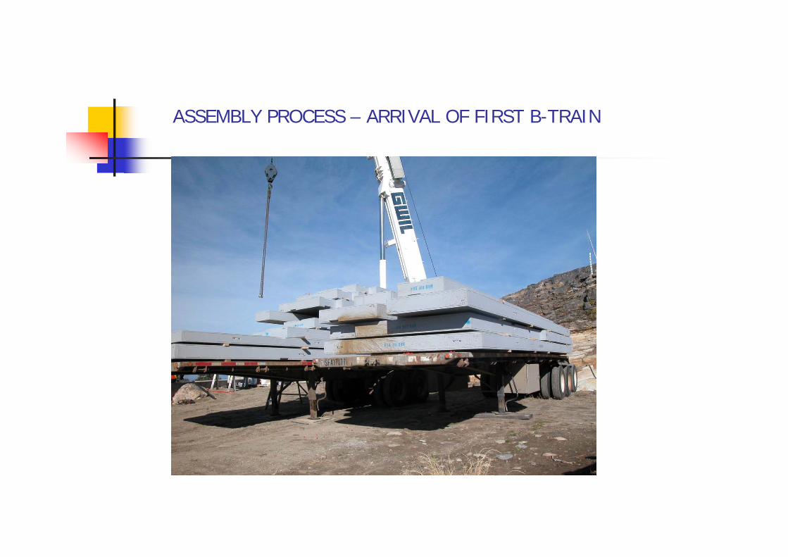
ASSEMBLY PROCESS – ARRIVAL OF FIRST B-TRAIN
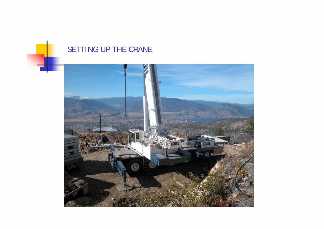
SETTING UP THE CRANE
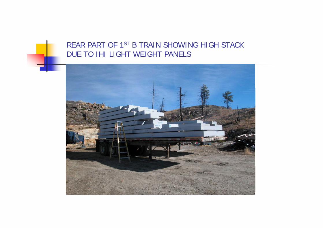
REAR PART OF 1ST B TRAIN SHOWING HIGH STACK DUE TO IHI LIGHT WEIGHT PANELS


UNLOADING PANELS 2 AT A TIME DUE TO LIGHT WEIGHT
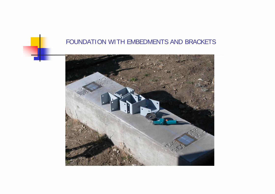
FOUNDATION WITH EMBEDMENTS AND BRACKETS

IHI PANELS ARE DESIGNED TO WORK IN TENSION, COMPRESSION, TORSION AND CANTILEVER

CHIEF PROJECT OFFICER WITH CLIENT IN THE MIDDLE AND THE CONSTRUCTION MANAGER TO THE LEFT OF THE PICTURE

VARIOUS EMBEDMENTS LOCATED AT DIFFERENT FOUNDATION LEVELS AND WALLS

DAY 2

PERFECT FIT
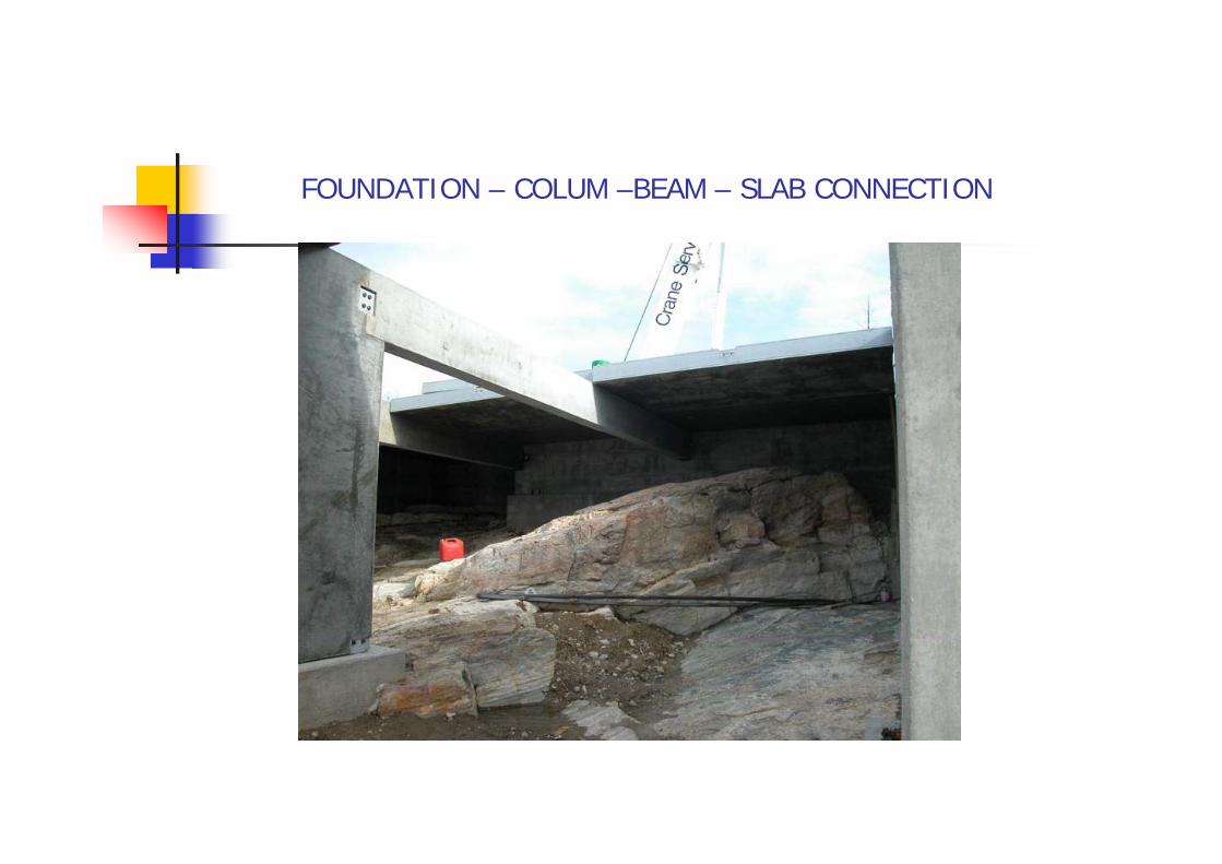
FOUNDATION – COLUM –BEAM – SLAB CONNECTION

PANEL FOR THE TERRACE WITH HIGHER BRACKET ANGLES TOPANEL FOR THE TERRACE WITH HIGHER BRACKET ANGLES TO CREATE A SUNKEN SLAB WITH RESPECT TO THE INTERIOR SLABPANELS – PICTURE SHOWS SOME OF OUR ALBERTA PARTNERS

1 – 2 MAN INSTALLATION

ANOTHER NICE ALIGNEMENT PRIOR TO FINAL POSITIONING
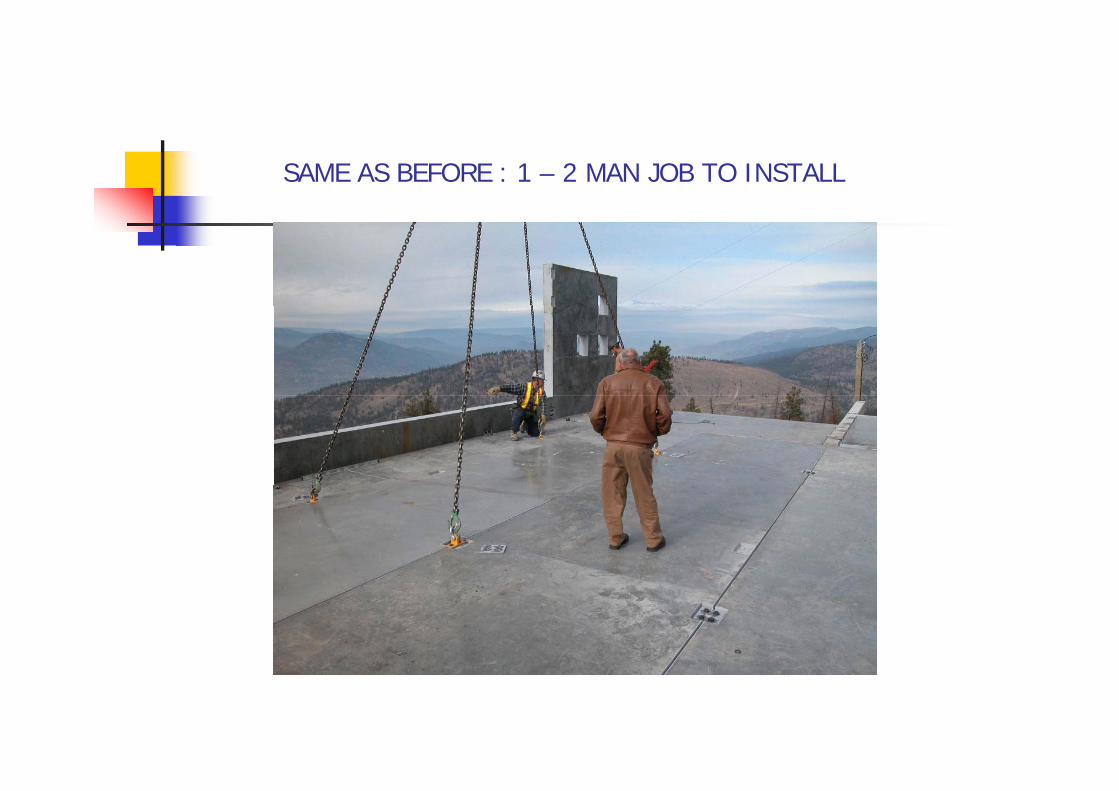
SAME AS BEFORE : 1 – 2 MAN JOB TO INSTALL
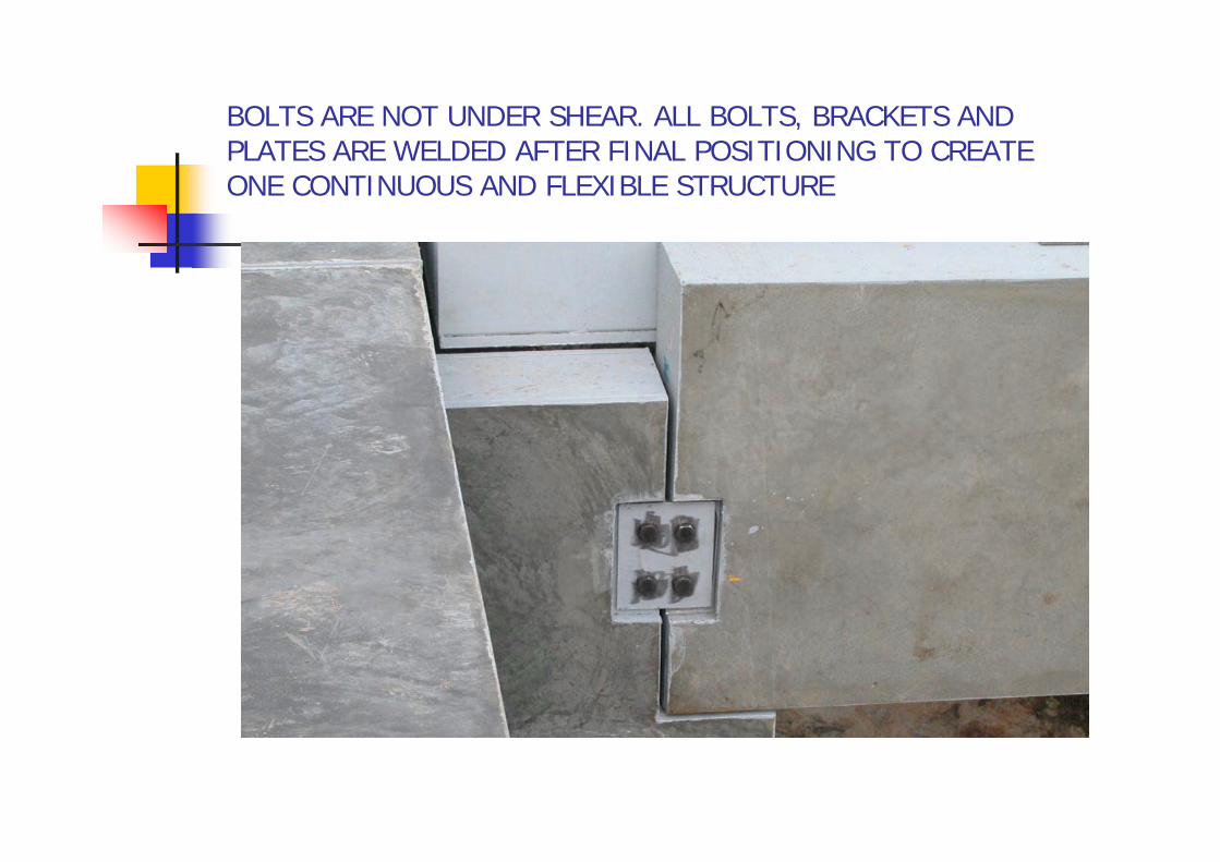
BOLTS ARE NOT UNDER SHEAR. ALL BOLTS, BRACKETS AND PLATES ARE WELDED AFTER FINAL POSITIONING TO CREATE ONE CONTINUOUS AND FLEXIBLE STRUCTURE
ASSEMBLY PROCESS
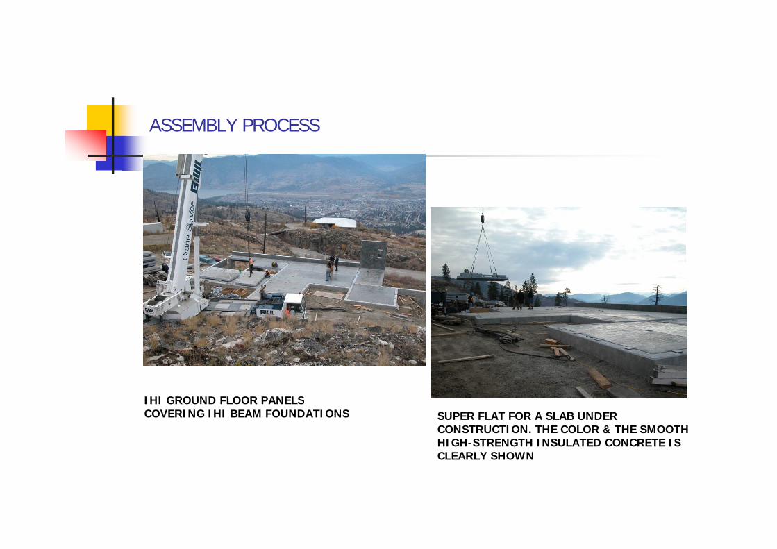
IHI GROUND FLOOR PANELSIHI GROUND FLOOR PANELSCOVERING IHI BEAM FOUNDATIONS SUPER FLAT FOR A SLAB UNDER
CONSTRUCTION. THE COLOR & THE SMOOTH HIGH-STRENGTH INSULATED CONCRETE IS CLEARLY SHOWN

ASSEMBLY PROCESS
THE STRENGTH TO WEIGHT RATIO OF EACH PANEL IS VERY HIGH, GIVING NATURALLY ZERO SAG WHEN LIFTED WITH EVEN LARGER SPANS.
BEAUTIFUL VIEW OF THE SLOPED SITE SHOWING SOME OF THE GROUND FLOOR WALL PANELS BEING ERECTED.

ASSEMBLY PROCESS
CLOSER LOOK OF GROUND FLOOR SAME FOR INTERIOR PANELSEXTERIOR WALL PANELS WITH INTEGRATED ELECTRICAL SERVICES AND CONCEALED CONNECTIONS

ASSEMBLY PROCESS
THE BEAUTY OF THE IHI SYSTEM IS THAT EVEN IF SOME BRACKETS OR HOLES DON’T LINE UP 100% FOR WHATEVER REASON, ONE CAN JUST ,WELD THEM TO KEEP UP MOVING RATHER THAN TRYING TO HAVE A PERFECT PICTURE WITHOUT COMPREMISING IT ON STRENGTH.
ONE LARGE EXTERIOR WALL WITH LOTS OF OPENINGS TEMPORARILY BRACED AT BOTTOM OF DOOR OPENINGS. IN SOME CASES THE OIPENINGS ARE DIAGONALLY BRACEDBRACED.
ASSEMBLY PROCESS
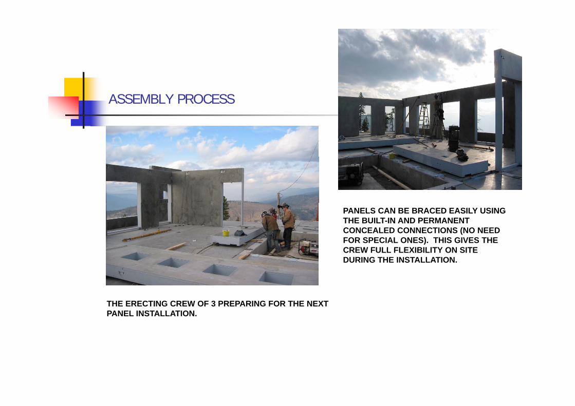
PANELS CAN BE BRACED EASILY USING THE BUILT-IN AND PERMANENT CONCEALED CONNECTIONS (NO NEED FOR SPECIAL ONES). THIS GIVES THE CREW FULL FLEXIBILITY ON SITECREW FULL FLEXIBILITY ON SITE DURING THE INSTALLATION.
THE ERECTING CREW OF 3 PREPARING FOR THE NEXT PANEL INSTALLATION.
ASSEMBLY PROCESS
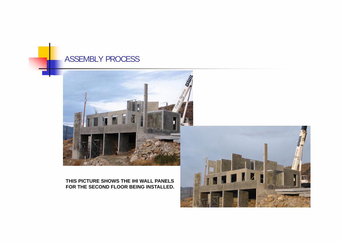
THIS PICTURE SHOWS THE IHI WALL PANELS FOR THE SECOND FLOOR BEING INSTALLED.

ASSEMBLY PROCESS
INTERIOR UPPER FLOOR PANELS SHOWING BUILT-IN ELECTRICAL BOXES & CONDUITS. THERE IS NO NEED FOR DRY WALLS OR PLASTERING, JUST 2 COATS OF ELASTOMERE PAINT OVER THE FACTORY SEALED PANELS IS ENOUGH.
A LOWER PERSPECTIVE OF THE DECORATIVE IHI SUSPENDED PERGOLA PANEL (TO BE).PERGOLA PANEL (TO BE).

ASSEMBLY PROCESS
INSTALLING THE ROOF PANELS WITH A LAST MINUTE DECISION BY THE CLIENT BASED ON IHI’S RECOMMENDATION TO SLOPE THE PANELS RATHER THAN ADDING THE RIGID EPS ON TOPRATHER THAN ADDING THE RIGID EPS ON TOP WITH A MEMBRANE PRACTICED CONVENTIONALLY IN CONSTRUCTION.
UPPER VIEW PERSPECTIVE OF THE SUSPENDED IHI PERGOLA PANEL (TO BE).
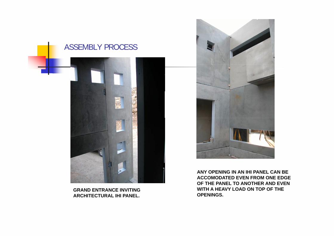
ASSEMBLY PROCESS
ANY OPENING IN AN IHI PANEL CAN BE
GRAND ENTRANCE INVITING ARCHITECTURAL IHI PANEL.
ANY OPENING IN AN IHI PANEL CAN BE ACCOMODATED EVEN FROM ONE EDGE OF THE PANEL TO ANOTHER AND EVEN WITH A HEAVY LOAD ON TOP OF THE OPENINGS.
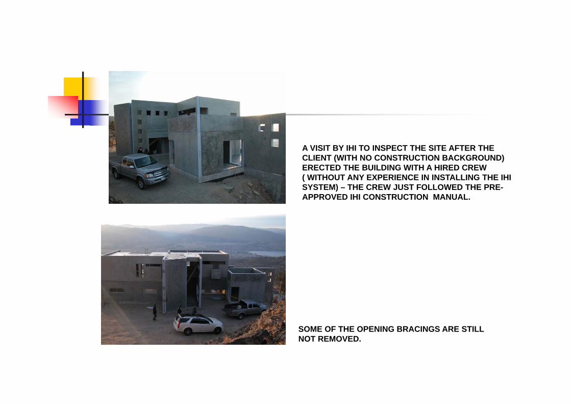
A VISIT BY IHI TO INSPECT THE SITE AFTER THE CLIENT (WITH NO CONSTRUCTION BACKGROUND)CLIENT (WITH NO CONSTRUCTION BACKGROUND) ERECTED THE BUILDING WITH A HIRED CREW ( WITHOUT ANY EXPERIENCE IN INSTALLING THE IHI SYSTEM) – THE CREW JUST FOLLOWED THE PRE-APPROVED IHI CONSTRUCTION MANUAL.
SOME OF THE OPENING BRACINGS ARE STILL NOT REMOVEDNOT REMOVED.

ASSEMBLY PROCESS
“A MASTER ARCHITECTURAL PIECE” SAID THE PRESIDENT OF IHI, IN SPITE OF THE FACT THAT FOR BUDGETARY REASONS THE CLIENT DECIDED TO BUILD THE HOUSE IN TWO PHASES WITHOUTDECIDED TO BUILD THE HOUSE IN TWO PHASES, WITHOUT COMPROMISING MUCH ON THE FIRST PHASE AS SHOWN ABOVE.
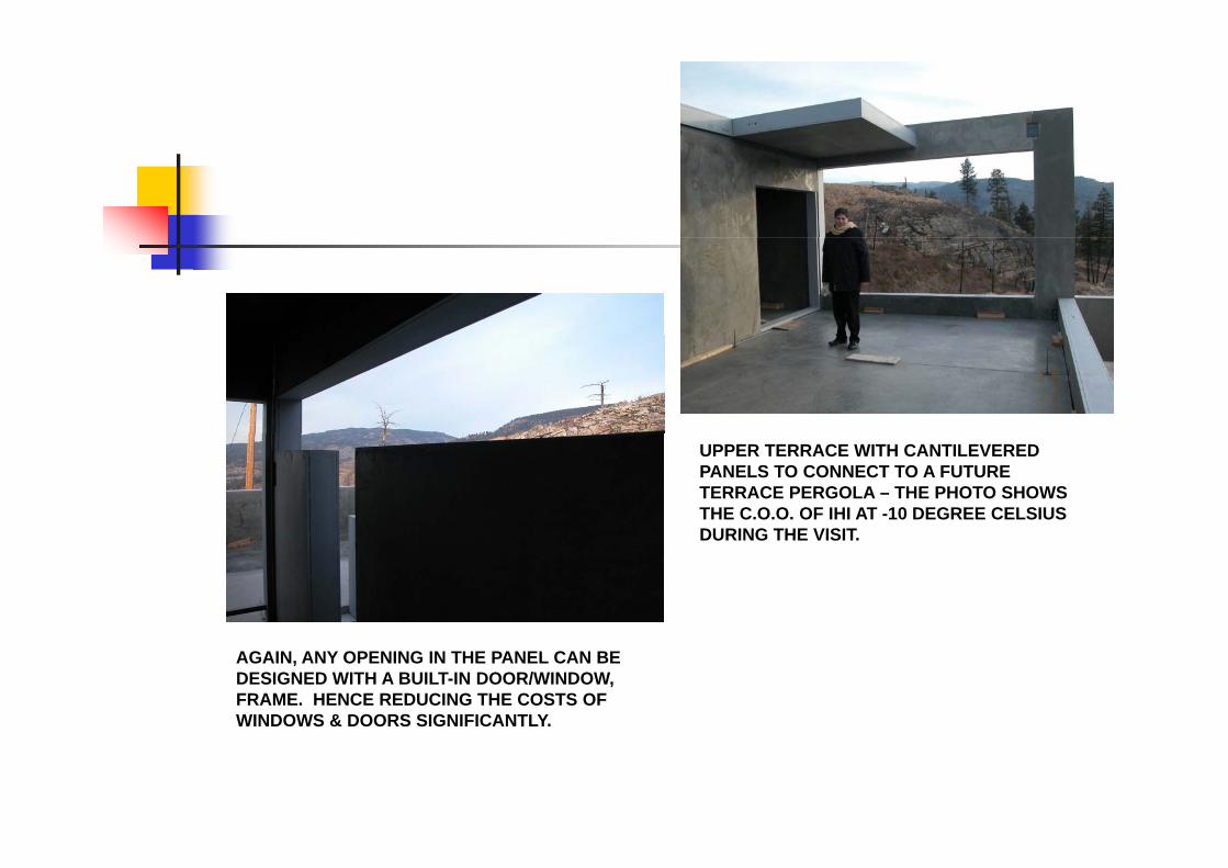
UPPER TERRACE WITH CANTILEVERED PANELS TO CONNECT TO A FUTURE TERRACE PERGOLA – THE PHOTO SHOWS THE C.O.O. OF IHI AT -10 DEGREE CELSIUS DURING THE VISITDURING THE VISIT.
AGAIN, ANY OPENING IN THE PANEL CAN BE DESIGNED WITH A BUILT-IN DOOR/WINDOW, FRAME. HENCE REDUCING THE COSTS OF WINDOWS & DOORS SIGNIFICANTLY.

ASSEMBLING PROCESS
THESE PHOTOS WERE TAKEN BY THETHESE PHOTOS WERE TAKEN BY THE PRESIDENT AND C.E.O. OF IHI PERSONALLY DURING THE VISIT.
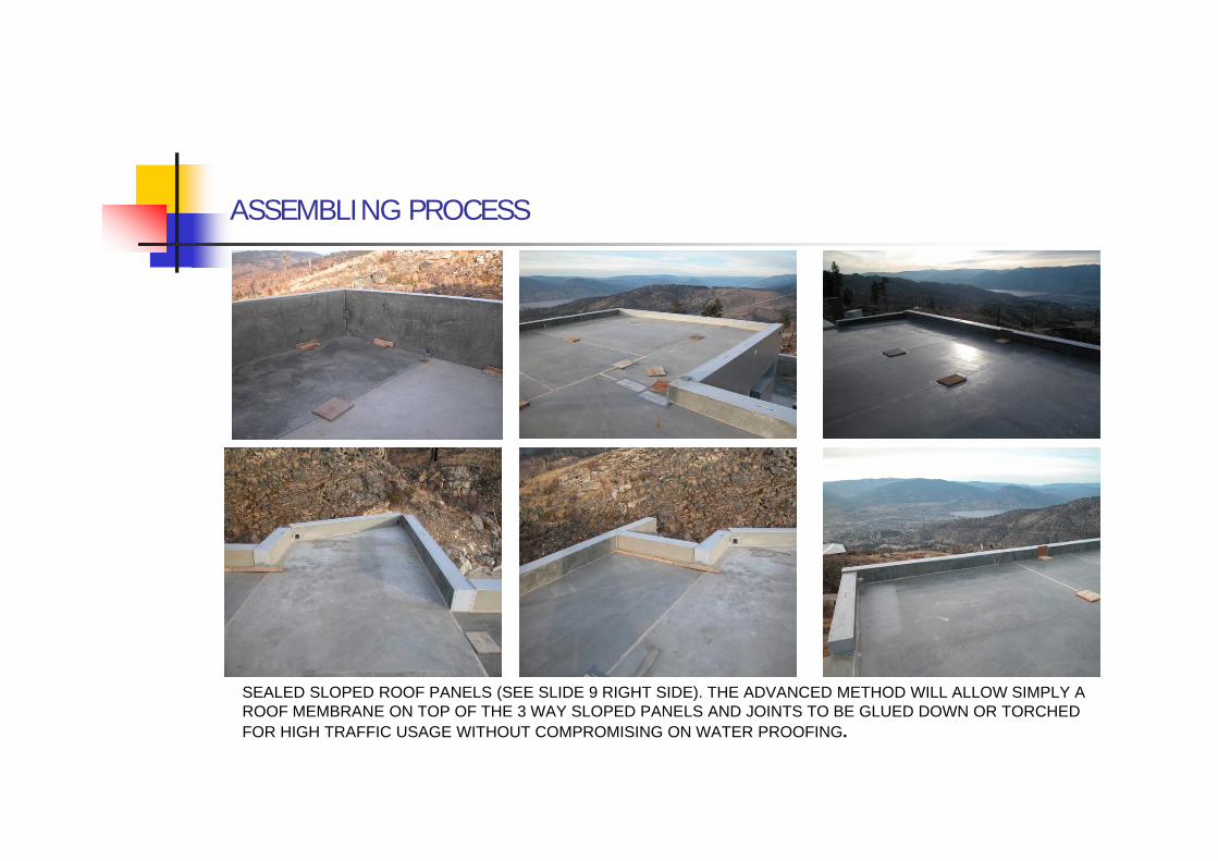
ASSEMBLING PROCESS
SEALED SLOPED ROOF PANELS (SEE SLIDE 9 RIGHT SIDE). THE ADVANCED METHOD WILL ALLOW SIMPLY A ROOF MEMBRANE ON TOP OF THE 3 WAY SLOPED PANELS AND JOINTS TO BE GLUED DOWN OR TORCHED FOR HIGH TRAFFIC USAGE WITHOUT COMPROMISING ON WATER PROOFING.
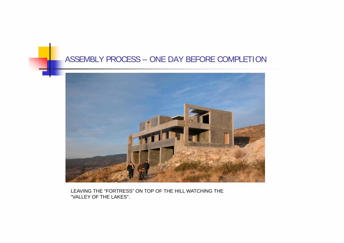
ASSEMBLY PROCESS – ONE DAY BEFORE COMPLETION
LEAVING THE “FORTRESS” ON TOP OF THE HILL WATCHING THE “VALLEY OF THE LAKES”.
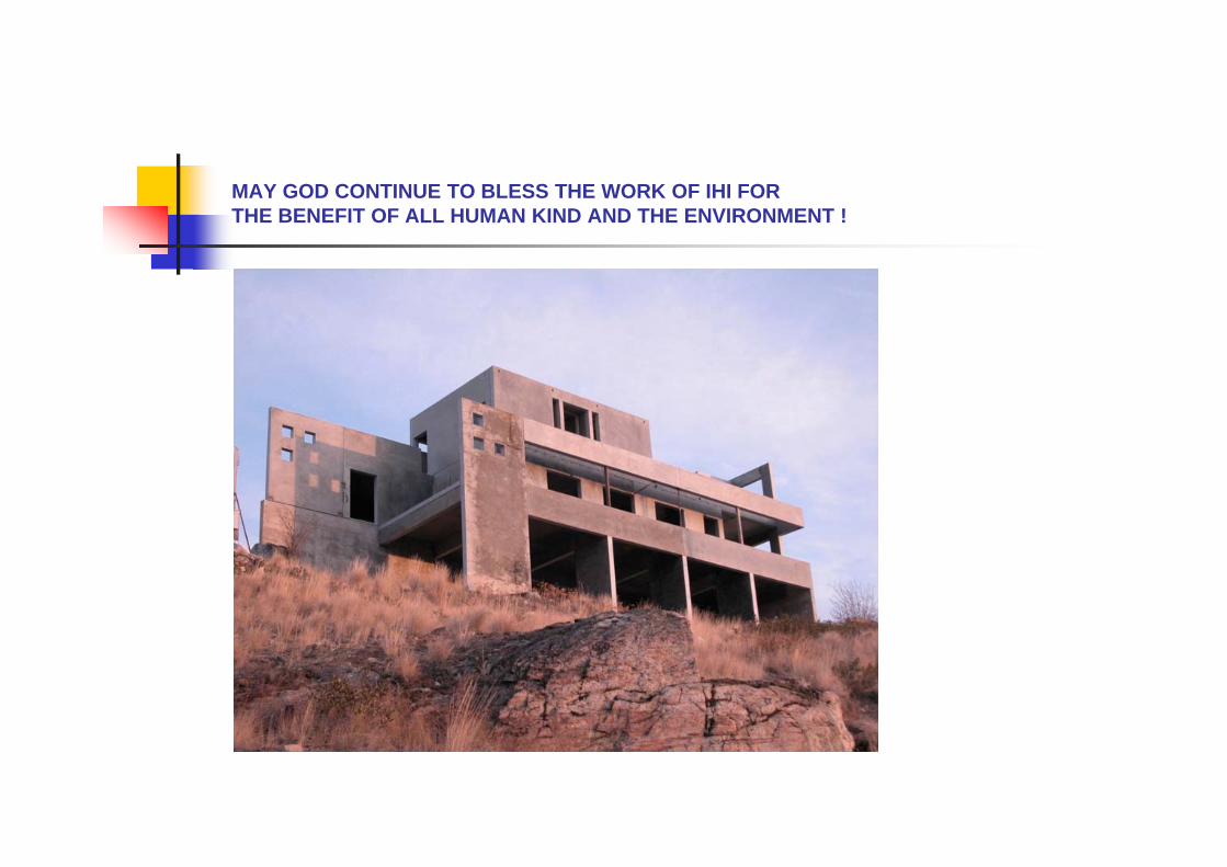
MAY GOD CONTINUE TO BLESS THE WORK OF IHI FOR THE BENEFIT OF ALL HUMAN KIND AND THE ENVIRONMENT !