im943 - lincoln electric
TRANSCRIPT

POWER WAVE ® I400
Operator’s Manual
Save for future reference
Date Purchased
Code: (ex: 10859)
Serial: (ex: U1060512345)
IM943-A | Issue D ate 12-Aug
© Lincoln Global, Inc. All Rights Reserved.
For use with machines having Code Numbers:
11454, 11454R, 11774
Register your machine: www.lincolnelectric.com/register
Authorized Service and Distributor Locator: www.lincolnelectric.com/locator
Need Help? Call 1.888.935.3877 to talk to a Service Representative
Hours of Operation: 8:00 AM to 6:00 PM (ET) Mon. thru Fri.
After hours? Use “Ask the Experts” at lincolnelectric.comA Lincoln Service Representative will contact you no later than the following business day.
For Service outside the USA: Email: [email protected]
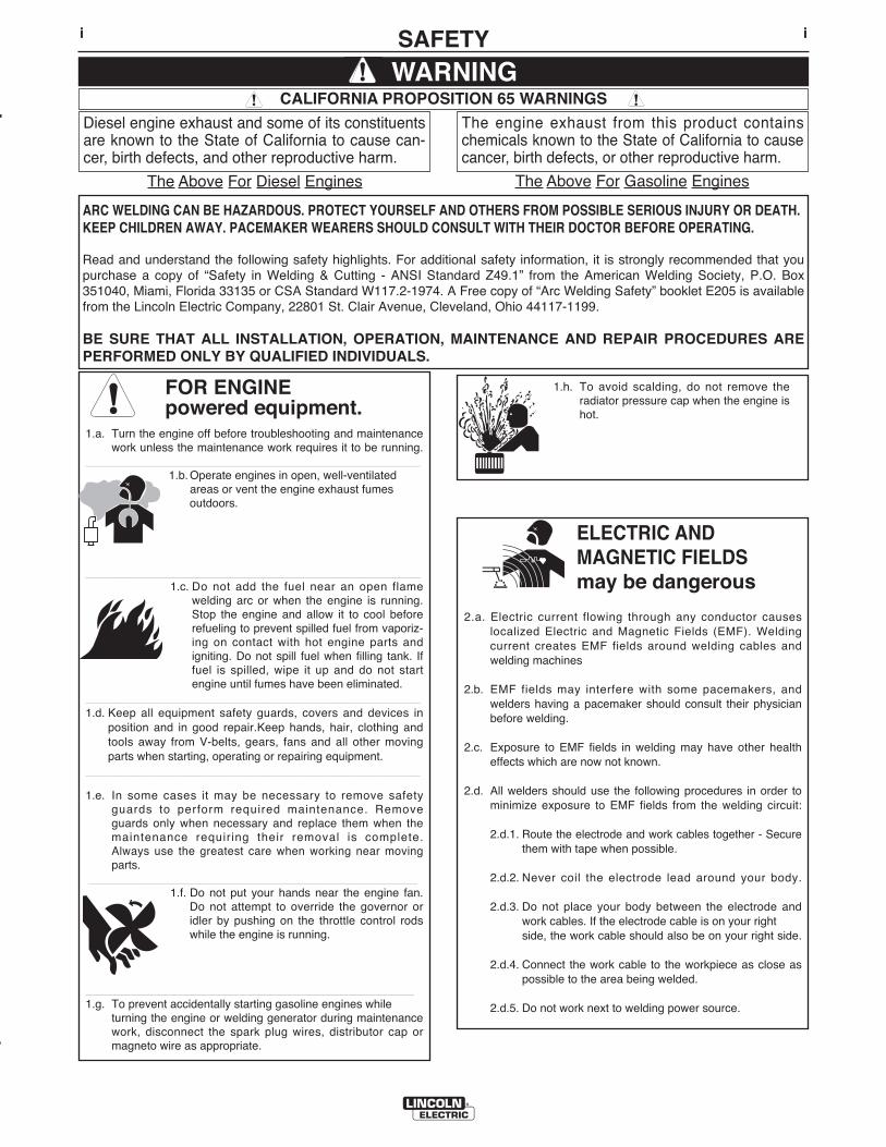
FOR ENGINEpowered equipment.
1.a. Turn the engine off before troubleshooting and maintenancework unless the maintenance work requires it to be running.
____________________________________________________1.b. Operate engines in open, well-ventilated
areas or vent the engine exhaust fumes outdoors.
____________________________________________________1.c. Do not add the fuel near an open flame
welding arc or when the engine is running.Stop the engine and allow it to cool beforerefueling to prevent spilled fuel from vaporiz-ing on contact with hot engine parts andigniting. Do not spill fuel when filling tank. Iffuel is spilled, wipe it up and do not startengine until fumes have been eliminated.
____________________________________________________1.d. Keep all equipment safety guards, covers and devices in
position and in good repair.Keep hands, hair, clothing andtools away from V-belts, gears, fans and all other movingparts when starting, operating or repairing equipment.
____________________________________________________
1.e. In some cases it may be necessary to remove safetyguards to perform required maintenance. Removeguards only when necessary and replace them when themaintenance requiring their removal is complete.Always use the greatest care when working near movingparts.
___________________________________________________1.f. Do not put your hands near the engine fan.
Do not attempt to override the governor oridler by pushing on the throttle control rodswhile the engine is running.
___________________________________________________1.g. To prevent accidentally starting gasoline engines while
turning the engine or welding generator during maintenancework, disconnect the spark plug wires, distributor cap ormagneto wire as appropriate.
iSAFETYi
ARC WELDING CAN BE HAZARDOUS. PROTECT YOURSELF AND OTHERS FROM POSSIBLE SERIOUS INJURY OR DEATH.KEEP CHILDREN AWAY. PACEMAKER WEARERS SHOULD CONSULT WITH THEIR DOCTOR BEFORE OPERATING.
Read and understand the following safety highlights. For additional safety information, it is strongly recommended that youpurchase a copy of “Safety in Welding & Cutting - ANSI Standard Z49.1” from the American Welding Society, P.O. Box351040, Miami, Florida 33135 or CSA Standard W117.2-1974. A Free copy of “Arc Welding Safety” booklet E205 is availablefrom the Lincoln Electric Company, 22801 St. Clair Avenue, Cleveland, Ohio 44117-1199.
BE SURE THAT ALL INSTALLATION, OPERATION, MAINTENANCE AND REPAIR PROCEDURES AREPERFORMED ONLY BY QUALIFIED INDIVIDUALS.
WARNING
ELECTRIC AND MAGNETIC FIELDSmay be dangerous
2.a. Electric current flowing through any conductor causes localized Electric and Magnetic Fields (EMF). Welding current creates EMF fields around welding cables and welding machines
2.b. EMF fields may interfere with some pacemakers, andwelders having a pacemaker should consult their physicianbefore welding.
2.c. Exposure to EMF fields in welding may have other healtheffects which are now not known.
2.d. All welders should use the following procedures in order tominimize exposure to EMF fields from the welding circuit:
2.d.1. Route the electrode and work cables together - Securethem with tape when possible.
2.d.2. Never coil the electrode lead around your body.
2.d.3. Do not place your body between the electrode andwork cables. If the electrode cable is on your right side, the work cable should also be on your right side.
2.d.4. Connect the work cable to the workpiece as close aspossible to the area being welded.
2.d.5. Do not work next to welding power source.
1.h. To avoid scalding, do not remove theradiator pressure cap when the engine ishot.
CALIFORNIA PROPOSITION 65 WARNINGS
Diesel engine exhaust and some of its constituentsare known to the State of California to cause can-cer, birth defects, and other reproductive harm.
The engine exhaust from this product containschemicals known to the State of California to causecancer, birth defects, or other reproductive harm.
The Above For Diesel Engines The Above For Gasoline Engines
iiSAFETYii
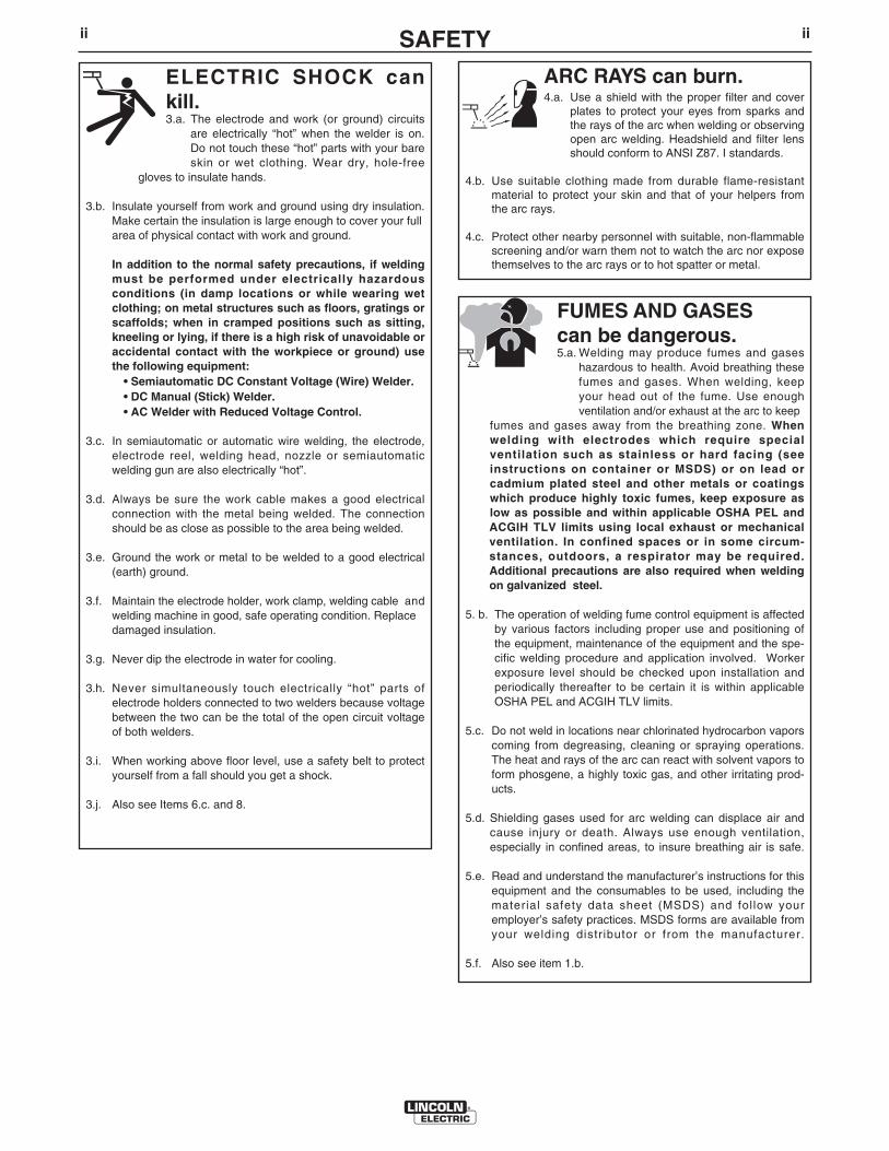
ARC RAYS can burn.4.a. Use a shield with the proper filter and cover
plates to protect your eyes from sparks andthe rays of the arc when welding or observingopen arc welding. Headshield and filter lensshould conform to ANSI Z87. I standards.
4.b. Use suitable clothing made from durable flame-resistantmaterial to protect your skin and that of your helpers fromthe arc rays.
4.c. Protect other nearby personnel with suitable, non-flammablescreening and/or warn them not to watch the arc nor exposethemselves to the arc rays or to hot spatter or metal.
ELECTRIC SHOCK cankill.3.a. The electrode and work (or ground) circuits
are electrically “hot” when the welder is on.Do not touch these “hot” parts with your bareskin or wet clothing. Wear dry, hole-free
gloves to insulate hands.
3.b. Insulate yourself from work and ground using dry insulation.Make certain the insulation is large enough to cover your fullarea of physical contact with work and ground.
In addition to the normal safety precautions, if weldingmust be performed under electrically hazardousconditions (in damp locations or while wearing wetclothing; on metal structures such as floors, gratings orscaffolds; when in cramped positions such as sitting,kneeling or lying, if there is a high risk of unavoidable oraccidental contact with the workpiece or ground) usethe following equipment:
• Semiautomatic DC Constant Voltage (Wire) Welder.• DC Manual (Stick) Welder.• AC Welder with Reduced Voltage Control.
3.c. In semiautomatic or automatic wire welding, the electrode,electrode reel, welding head, nozzle or semiautomaticwelding gun are also electrically “hot”.
3.d. Always be sure the work cable makes a good electricalconnection with the metal being welded. The connectionshould be as close as possible to the area being welded.
3.e. Ground the work or metal to be welded to a good electrical(earth) ground.
3.f. Maintain the electrode holder, work clamp, welding cable andwelding machine in good, safe operating condition. Replacedamaged insulation.
3.g. Never dip the electrode in water for cooling.
3.h. Never simultaneously touch electrically “hot” parts ofelectrode holders connected to two welders because voltagebetween the two can be the total of the open circuit voltageof both welders.
3.i. When working above floor level, use a safety belt to protectyourself from a fall should you get a shock.
3.j. Also see Items 6.c. and 8.
FUMES AND GASEScan be dangerous.5.a. Welding may produce fumes and gases
hazardous to health. Avoid breathing thesefumes and gases. When welding, keepyour head out of the fume. Use enoughventilation and/or exhaust at the arc to keep
fumes and gases away from the breathing zone. Whenwelding with electrodes which require specialventilation such as stainless or hard facing (seeinstructions on container or MSDS) or on lead orcadmium plated steel and other metals or coatingswhich produce highly toxic fumes, keep exposure aslow as possible and within applicable OSHA PEL and ACGIH TLV limits using local exhaust or mechanicalventilation. In confined spaces or in some circum-stances, outdoors, a respirator may be required.Additional precautions are also required when weldingon galvanized steel.
5. b. The operation of welding fume control equipment is affectedby various factors including proper use and positioning ofthe equipment, maintenance of the equipment and the spe-cific welding procedure and application involved. Workerexposure level should be checked upon installation andperiodically thereafter to be certain it is within applicableOSHA PEL and ACGIH TLV limits.
5.c. Do not weld in locations near chlorinated hydrocarbon vaporscoming from degreasing, cleaning or spraying operations.The heat and rays of the arc can react with solvent vapors toform phosgene, a highly toxic gas, and other irritating prod-ucts.
5.d. Shielding gases used for arc welding can displace air andcause injury or death. Always use enough ventilation,especially in confined areas, to insure breathing air is safe.
5.e. Read and understand the manufacturer’s instructions for thisequipment and the consumables to be used, including thematerial safety data sheet (MSDS) and follow youremployer’s safety practices. MSDS forms are available fromyour welding distributor or from the manufacturer.
5.f. Also see item 1.b.
iiiSAFETYiii
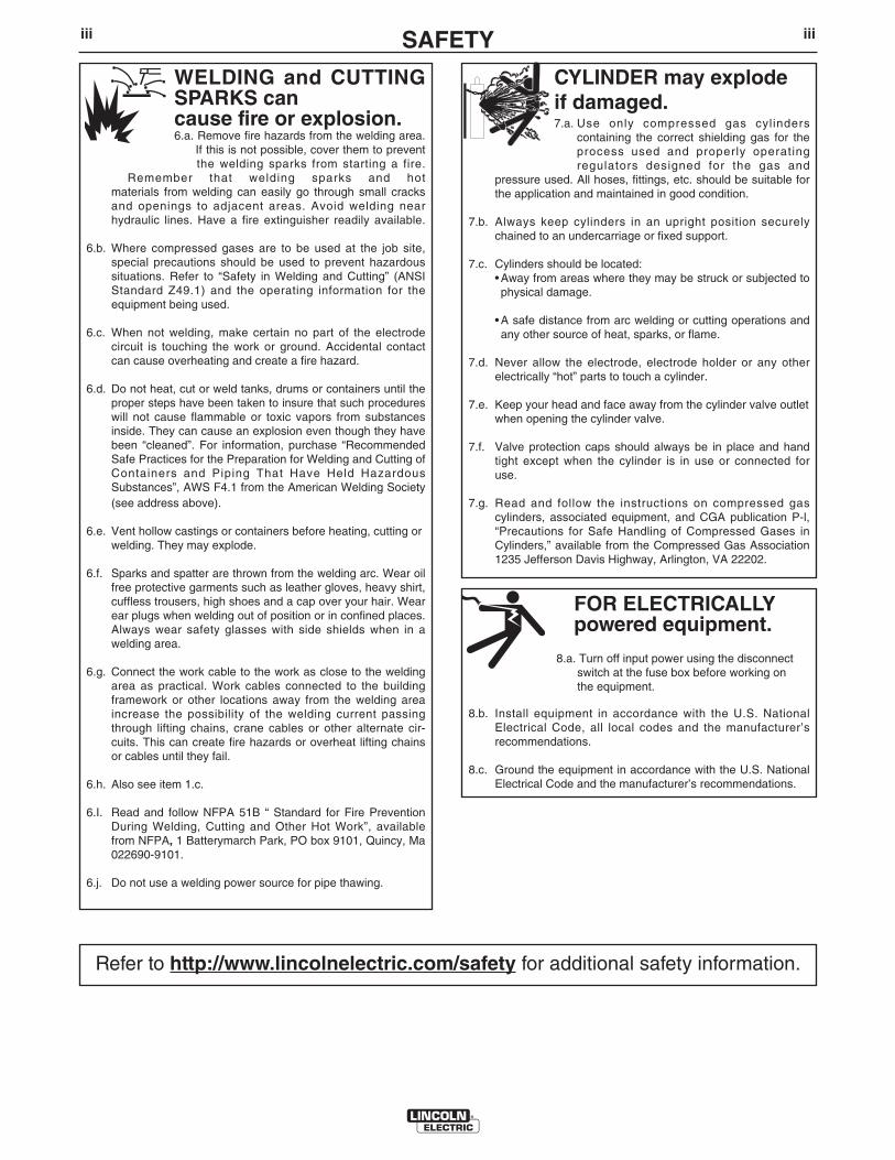
FOR ELECTRICALLYpowered equipment.
8.a. Turn off input power using the disconnectswitch at the fuse box before working onthe equipment.
8.b. Install equipment in accordance with the U.S. NationalElectrical Code, all local codes and the manufacturer’srecommendations.
8.c. Ground the equipment in accordance with the U.S. NationalElectrical Code and the manufacturer’s recommendations.
CYLINDER may explodeif damaged.7.a. Use only compressed gas cylinders
containing the correct shielding gas for theprocess used and properly operatingregulators designed for the gas and
pressure used. All hoses, fittings, etc. should be suitable forthe application and maintained in good condition.
7.b. Always keep cylinders in an upright position securelychained to an undercarriage or fixed support.
7.c. Cylinders should be located:• Away from areas where they may be struck or subjected tophysical damage.
• A safe distance from arc welding or cutting operations andany other source of heat, sparks, or flame.
7.d. Never allow the electrode, electrode holder or any otherelectrically “hot” parts to touch a cylinder.
7.e. Keep your head and face away from the cylinder valve outletwhen opening the cylinder valve.
7.f. Valve protection caps should always be in place and handtight except when the cylinder is in use or connected foruse.
7.g. Read and follow the instructions on compressed gascylinders, associated equipment, and CGA publication P-l,“Precautions for Safe Handling of Compressed Gases inCylinders,” available from the Compressed Gas Association1235 Jefferson Davis Highway, Arlington, VA 22202.
WELDING and CUTTINGSPARKS cancause fire or explosion.6.a. Remove fire hazards from the welding area.
If this is not possible, cover them to preventthe welding sparks from starting a fire.
Remember that welding sparks and hotmaterials from welding can easily go through small cracksand openings to adjacent areas. Avoid welding nearhydraulic lines. Have a fire extinguisher readily available.
6.b. Where compressed gases are to be used at the job site,special precautions should be used to prevent hazardoussituations. Refer to “Safety in Welding and Cutting” (ANSIStandard Z49.1) and the operating information for theequipment being used.
6.c. When not welding, make certain no part of the electrodecircuit is touching the work or ground. Accidental contactcan cause overheating and create a fire hazard.
6.d. Do not heat, cut or weld tanks, drums or containers until theproper steps have been taken to insure that such procedureswill not cause flammable or toxic vapors from substancesinside. They can cause an explosion even though they havebeen “cleaned”. For information, purchase “RecommendedSafe Practices for the Preparation for Welding and Cutting ofContainers and Piping That Have Held HazardousSubstances”, AWS F4.1 from the American Welding Society(see address above).
6.e. Vent hollow castings or containers before heating, cutting orwelding. They may explode.
6.f. Sparks and spatter are thrown from the welding arc. Wear oilfree protective garments such as leather gloves, heavy shirt,cuffless trousers, high shoes and a cap over your hair. Wearear plugs when welding out of position or in confined places.Always wear safety glasses with side shields when in awelding area.
6.g. Connect the work cable to the work as close to the weldingarea as practical. Work cables connected to the buildingframework or other locations away from the welding areaincrease the possibility of the welding current passingthrough lifting chains, crane cables or other alternate cir-cuits. This can create fire hazards or overheat lifting chainsor cables until they fail.
6.h. Also see item 1.c.
6.I. Read and follow NFPA 51B “ Standard for Fire PreventionDuring Welding, Cutting and Other Hot Work”, availablefrom NFPA, 1 Batterymarch Park, PO box 9101, Quincy, Ma022690-9101.
6.j. Do not use a welding power source for pipe thawing.
Refer to http://www.lincolnelectric.com/safety for additional safety information.
ivSAFETYiv
PRÉCAUTIONS DE SÛRETÉPour votre propre protection lire et observer toutes les instructionset les précautions de sûreté specifiques qui parraissent dans cemanuel aussi bien que les précautions de sûreté générales suiv-antes:
Sûreté Pour Soudage A LʼArc1. Protegez-vous contre la secousse électrique:
a. Les circuits à lʼélectrode et à la piéce sont sous tensionquand la machine à souder est en marche. Eviter toujourstout contact entre les parties sous tension et la peau nueou les vétements mouillés. Porter des gants secs et sanstrous pour isoler les mains.
b. Faire trés attention de bien sʼisoler de la masse quand onsoude dans des endroits humides, ou sur un planchermetallique ou des grilles metalliques, principalement dans les positions assis ou couché pour lesquelles une grandepartie du corps peut être en contact avec la masse.
c. Maintenir le porte-électrode, la pince de masse, le câblede soudage et la machine à souder en bon et sûr étatdefonctionnement.
d.Ne jamais plonger le porte-électrode dans lʼeau pour lerefroidir.
e. Ne jamais toucher simultanément les parties sous tensiondes porte-électrodes connectés à deux machines à souderparce que la tension entre les deux pinces peut être letotal de la tension à vide des deux machines.
f. Si on utilise la machine à souder comme une source decourant pour soudage semi-automatique, ces precautionspour le porte-électrode sʼapplicuent aussi au pistolet desoudage.
2. Dans le cas de travail au dessus du niveau du sol, se protégercontre les chutes dans le cas ou on recoit un choc. Ne jamaisenrouler le câble-électrode autour de nʼimporte quelle partiedu corps.
3. Un coup dʼarc peut être plus sévère quʼun coup de soliel,donc:
a. Utiliser un bon masque avec un verre filtrant appropriéainsi quʼun verre blanc afin de se protéger les yeux du ray-onnement de lʼarc et des projections quand on soude ouquand on regarde lʼarc.
b. Porter des vêtements convenables afin de protéger lapeau de soudeur et des aides contre le rayonnement delʻarc.
c. Protéger lʼautre personnel travaillant à proximité ausoudage à lʼaide dʼécrans appropriés et non-inflammables.
4. Des gouttes de laitier en fusion sont émises de lʼarc desoudage. Se protéger avec des vêtements de protection libresde lʼhuile, tels que les gants en cuir, chemise épaisse, pan-talons sans revers, et chaussures montantes.
5. Toujours porter des lunettes de sécurité dans la zone desoudage. Utiliser des lunettes avec écrans lateraux dans leszones où lʼon pique le laitier.
6. Eloigner les matériaux inflammables ou les recouvrir afin deprévenir tout risque dʼincendie dû aux étincelles.
7. Quand on ne soude pas, poser la pince à une endroit isolé dela masse. Un court-circuit accidental peut provoquer unéchauffement et un risque dʼincendie.
8. Sʼassurer que la masse est connectée le plus prés possiblede la zone de travail quʼil est pratique de le faire. Si on placela masse sur la charpente de la construction ou dʼautresendroits éloignés de la zone de travail, on augmente le risquede voir passer le courant de soudage par les chaines de lev-age, câbles de grue, ou autres circuits. Cela peut provoquerdes risques dʼincendie ou dʼechauffement des chaines et descâbles jusquʼà ce quʼils se rompent.
9. Assurer une ventilation suffisante dans la zone de soudage.Ceci est particuliérement important pour le soudage de tôlesgalvanisées plombées, ou cadmiées ou tout autre métal quiproduit des fumeés toxiques.
10. Ne pas souder en présence de vapeurs de chlore provenantdʼopérations de dégraissage, nettoyage ou pistolage. Lachaleur ou les rayons de lʼarc peuvent réagir avec les vapeursdu solvant pour produire du phosgéne (gas fortement toxique)ou autres produits irritants.
11. Pour obtenir de plus amples renseignements sur la sûreté,voir le code “Code for safety in welding and cutting” CSAStandard W 117.2-1974.
PRÉCAUTIONS DE SÛRETÉ POURLES MACHINES À SOUDER ÀTRANSFORMATEUR ET ÀREDRESSEUR
1. Relier à la terre le chassis du poste conformement au code delʼélectricité et aux recommendations du fabricant. Le dispositifde montage ou la piece à souder doit être branché à unebonne mise à la terre.
2. Autant que possible, Iʼinstallation et lʼentretien du poste seronteffectués par un électricien qualifié.
3. Avant de faires des travaux à lʼinterieur de poste, la debranch-er à lʼinterrupteur à la boite de fusibles.
4. Garder tous les couvercles et dispositifs de sûreté à leurplace.

vSAFETYv
Electromagnetic Compatibility (EMC)
ConformanceProducts displaying the CE mark are in conformity with European Community Council Directive of 15 Dec2004 on the approximation of the laws of the Member States relating to electromagnetic compatibility,2004/108/EC. It was manufactured in conformity with a national standard that implements a harmonizedstandard: EN 60974-10 Electromagnetic Compatibility (EMC) Product Standard for Arc Welding Equipment.It is for use with other Lincoln Electric equipment. It is designed for industrial and professional use.
IntroductionAll electrical equipment generates small amounts of electromagnetic emission. Electrical emission may betransmitted through power lines or radiated through space, similar to a radio transmitter. When emissionsare received by other equipment, electrical interference may result. Electrical emissions may affect manykinds of electrical equipment; other nearby welding equipment, radio and TV reception, numerical controlledmachines, telephone systems, computers, etc. Be aware that interference may result and extra precautionsmay be required when a welding power source is used in a domestic establishment.
Installation and UseThe user is responsible for installing and using the welding equipment according to the manufacturer’sinstructions. If electromagnetic disturbances are detected then it shall be the responsibility of the user of thewelding equipment to resolve the situation with the technical assistance of the manufacturer. In some casesthis remedial action may be as simple as earthing (grounding) the welding circuit, see Note. In other cases itcould involve construction of an electromagnetic screen enclosing the power source and the work completewith associated input filters. In all cases electromagnetic disturbances must be reduced to the point wherethey are no longer troublesome.
Note: The welding circuit may or may not be earthed for safety reasons according to national codes.Changing the earthing arrangements should only be authorized by a person who is compe-tent to access whether the changes will increase the risk of injury, e.g., by allowing parallelwelding current return paths which may damage the earth circuits of other equipment.
Assessment of AreaBefore installing welding equipment the user shall make an assessment of potential electromagnetic prob-lems in the surrounding area. The following shall be taken into account:
a) other supply cables, control cables, signaling and telephone cables; above, below and adjacent to thewelding equipment;
b) radio and television transmitters and receivers;
c) computer and other control equipment;
d) safety critical equipment, e.g., guarding of industrial equipment;
e) the health of the people around, e.g., the use of pacemakers and hearing aids;
f) equipment used for calibration or measurement
g) the immunity of other equipment in the environment. The user shall ensure that other equipment beingused in the environment is compatible. This may require additional protection measures;
h) the time of day that welding or other activities are to be carried out.

viSAFETYvi
Electromagnetic Compatibility (EMC)
The size of the surrounding area to be considered will depend on the structure of the building and otheractivities that are taking place. The surrounding area may extend beyond the boundaries of the premises.
Methods of Reducing Emissions
Mains SupplyWelding equipment should be connected to the mains supply according to the manufacturer’s recommenda-tions. If interference occurs, it may be necessary to take additional precautions such as filtering of the mainssupply. Consideration should be given to shielding the supply cable of permanently installed welding equip-ment, in metallic conduit or equivalent. Shielding should be electrically continuous throughout its length. Theshielding should be connected to the welding power source so that good electrical contact is maintainedbetween the conduit and the welding power source enclosure.
Maintenance of the Welding EquipmentThe welding equipment should be routinely maintained according to the manufacturer’s recommendations.All access and service doors and covers should be closed and properly fastened when the welding equip-ment is in operation. The welding equipment should not be modified in any way except for those changesand adjustments covered in the manufacturers instructions. In particular, the spark gaps of arc striking andstabilizing devices should be adjusted and maintained according to the manufacturer’s recommendations.
Welding CablesThe welding cables should be kept as short as possible and should be positioned close together, running ator close to floor level.
Equipotential BondingBonding of all metallic components in the welding installation and adjacent to it should be considered.However, metallic components bonded to the work piece will increase the risk that the operator couldreceive a shock by touching these metallic components and the electrode at the same time. The operatorshould be insulated from all such bonded metallic components.
Earthing of the WorkpieceWhere the workpiece is not bonded to earth for electrical safety, not connected to earth because of its sizeand position, e.g., ships hull or building steelwork, a connection bonding the workpiece to earth may reduceemissions in some, but not all instances. Care should be taken to prevent the earthing of the workpieceincreasing the risk of injury to users, or damage to other electrical equipment. Where necessary, the connec-tion of the workpiece to earth should be made by a direct connection to the workpiece, but in some countrieswhere direct connection is not permitted, the bonding should be achieved by suitable capacitance, selectedaccording to national regulations.
Screening and ShieldingSelective screening and shielding of other cables and equipment in the surrounding area may alleviate prob-lems of interference. Screening of the entire welding installation may be considered for special
applications1.
_________________________
1 Portions of the preceding text are contained in EN 60974-10: “Electromagnetic Compatibility (EMC) prod-uct standard for arc welding equipment.”

viivii
Thank You for selecting a QUALITY product by Lincoln Electric. We want youto take pride in operating this Lincoln Electric Company product••• as much pride as we have in bringing this product to you!
Read this Operators Manual completely before attempting to use this equipment. Save this manual and keep ithandy for quick reference. Pay particular attention to the safety instructions we have provided for your protection.The level of seriousness to be applied to each is explained below:
WARNINGThis statement appears where the information must be followed exactly to avoid serious personal injury or loss of life.
This statement appears where the information must be followed to avoid minor personal injury or damage to this equipment.
CAUTION
Please Examine Carton and Equipment For Damage ImmediatelyWhen this equipment is shipped, title passes to the purchaser upon receipt by the carrier. Consequently, Claimsfor material damaged in shipment must be made by the purchaser against the transportation company at thetime the shipment is received.
Please record your equipment identification information below for future reference. This information can befound on your machine nameplate.
Product _________________________________________________________________________________
Model Number ___________________________________________________________________________
Code Number or Date Code_________________________________________________________________
Serial Number____________________________________________________________________________
Date Purchased___________________________________________________________________________
Where Purchased_________________________________________________________________________
Whenever you request replacement parts or information on this equipment, always supply the information youhave recorded above. The code number is especially important when identifying the correct replacement parts.
On-Line Product Registration- Register your machine with Lincoln Electric either via fax or over the Internet.• For faxing: Complete the form on the back of the warranty statement included in the literature packet
accompanying this machine and fax the form per the instructions printed on it.• For On-Line Registration: Go to our WEB SITE at www.lincolnelectric.com. Choose “Support” and then “Register
Your Product”. Please complete the form and submit your registration.
CUSTOMER ASSISTANCE POLICYThe business of The Lincoln Electric Company is manufacturing and selling high quality welding equipment, consumables, and cutting equip-ment. Our challenge is to meet the needs of our customers and to exceed their expectations. On occasion, purchasers may ask LincolnElectric for advice or information about their use of our products. We respond to our customers based on the best information in our posses-sion at that time. Lincoln Electric is not in a position to warrant or guarantee such advice, and assumes no liability, with respect to such infor-mation or advice. We expressly disclaim any warranty of any kind, including any warranty of fitness for any customerʼs particular purpose,with respect to such information or advice. As a matter of practical consideration, we also cannot assume any responsibility for updating orcorrecting any such information or advice once it has been given, nor does the provision of information or advice create, expand or alter anywarranty with respect to the sale of our products.
Lincoln Electric is a responsive manufacturer, but the selection and use of specific products sold by Lincoln Electric is solely within the controlof, and remains the sole responsibility of the customer. Many variables beyond the control of Lincoln Electric affect the results obtained inapplying these types of fabrication methods and service requirements.
Subject to Change – This information is accurate to the best of our knowledge at the time of printing. Please refer to www.lincolnelectric.comfor any updated information.

viii TABLE OF CONTENTSPage
Installation .......................................................................................................Section ATechnical Specifications - POWER WAVE® i400...........................................A-1, A-2Safety Precautions.................................................................................................A-3Location and Mounting ..........................................................................................A-3Environmental Considerations...............................................................................A-3Lifting .....................................................................................................................A-3Stacking.................................................................................................................A-3Electromagnetic Compatibility ...............................................................................A-4Input and Grounding Connections.........................................................................A-4Input Connection....................................................................................................A-4Reconnect Diagram...............................................................................................A-5Connection Diagrams and Systems................................................................A-6,A-7
Fanuc R30iA / R30iB Controller Mounting ......................................................A-8Typical Integrated Systems (Single Arm)........................................................A-9Typical Stand Alone Systems (Single Arm) ..................................................A-10Typical Master / Slave System (Dual Arm) ...................................................A-11Typical F355i Retrofit (Single Arm) ...............................................................A-12
Electrode and Work Connections, General Guidelines .......................................A-13Cable Inductance, and its Effects on Welding .....................................................A-14Remote Sense Lead Connections .............................................................A-14,A-15Sense Lead Diagrams of Circumferential Applications........................................A-16Control Cable Connections..................................................................................A-17Common Equipment Connections ..............................................................A-17,A-18DeviceNet Configuration, Other Set-up Issues...................................................A-18________________________________________________________________________
Operation .........................................................................................................Section BSafety Precautions.................................................................................................B-1Graphic Symbols ...................................................................................................B-2Product Description ...............................................................................................B-3Recommended Processes and Equipment ...........................................................B-3
Recommended Processes ..............................................................................B-3Process and Equipment Limitations................................................................B-3Case Front Controls ................................................................................B-4, B-5Case Back Controls ........................................................................................B-5Internal Controls, Power Up Sequence...........................................................B-6Duty Cycle.......................................................................................................B-6Basic Welding Controls ...................................................................................B-7Constant Voltage Welding...............................................................................B-7Pulse Welding .................................................................................................B-8________________________________________________________________________
Accessories .....................................................................................................Section COptional Equipment ...............................................................................................C-1
Factory Installed..............................................................................................C-1Field Installed..................................................................................................C-1Compatible Lincoln Equipment .......................................................................C-1________________________________________________________________________
Maintenance ....................................................................................................Section DSafety Precautions ................................................................................................D-1Routine and Periodic Maintenance........................................................................D-1Calibration Specification, Chassis Removal Procedure ........................................D-1Capacitor Discharge Procedure ............................................................................D-2________________________________________________________________________
Troubleshooting ..............................................................................................Section EHow to use Troubleshooting Guide .......................................................................E-1Using the Status LED to Troubleshoot System Problems .....................................E-2Error Codes For POWER WAVE®..................................................................E-3, E-4Troubleshooting Guide...........................................................................E-5 thru E-14________________________________________________________________________
Wiring Diagram.............................................................................................Section F-1Dimension Print............................................................................................Section F-2________________________________________________________________________Parts Lists...............................................................................................................P-565________________________________________________________________________
viii
A-1INSTALLATION
POWER WAVE® i400
A-1
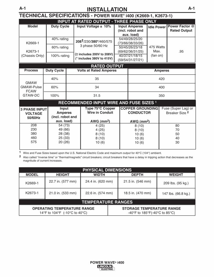
TECHNICAL SPECIFICATIONS - POWER WAVE® i400 (K2669-1, K2673-1)
RATED OUTPUT
RECOMMENDED INPUT WIRE AND FUSE SIZES 1
PHYSICAL DIMENSIONS
TEMPERATURE RANGES
INPUT AT RATED OUTPUT - THREE PHASE ONLYModel
K2669-1
K2673-1(Chassis Only)
Duty Cycle
40% rating
60% rating
100% rating
3 PHASE INPUTVOLTAGE50/60Hz
208230380460575
Input Amperes
(incl. robot andaux. load)
54 (73)49 (66)28 (38)25 (33)20 (26)
HEIGHT
22.7 in. (577 mm)
21.0 in. (533 mm)
MODEL
K2669-1
K2673-1
WIDTH
24.4 in. (620 mm)
22.6 in. (574 mm)
DEPTH
21.5 in. (546 mm)
18.5 in. (470 mm)
WEIGHT
209 lbs. (95 kg.)
147 lbs. (66.8 kg.)
Fuse (Super Lag) orBreaker Size 2
8070504030
COPPER GROUNDINGCONDUCTOR
AWG (mm2)8 (10)8 (10)10 (6)10 (6)10 (6)
Type 75°C CopperWire in Conduit
AWG (mm2) 4 (25)4 (25)8 (10)8 (10)10 (6)
Volts at Rated Amperes
35
34
31.5
Amperes
420
400
350
Duty Cycle
40%
60%
100%
Process
GMAWGMAW-Pulse
FCAWGTAW-DC
Input Amperes(incl. robot and
aux. load)54/49/28/25/20
(73/66/38/33/26)50/45/26/23/18
(69/62/36/31/25)40/37/21/18/15
(59/54/31/27/21)
Idle Power
475 WattsMax.
(fan on)
Power Factor @Rated Output
.95
Input Voltage ± 10%
208†/230/380*/460/5753 phase 50/60 Hz
(† includes 200V to 208V) (* includes 380V to 415V)
OPERATING TEMPERATURE RANGE14°F to 104°F (-10°C to 40°C)
STORAGE TEMPERATURE RANGE-40°F to 185°F(-40°C to 85°C)
1 Wire and Fuse Sizes based upon the U.S. National Electric Code and maximum output for 40°C (104°) ambient.2 Also called “inverse time” or “thermal/magnetic” circuit breakers; circuit breakers that have a delay in tripping action that decreases as the
magnitude of current increases.

A-2INSTALLATION
POWER WAVE® i400
A-2
TECHNICAL SPECIFICATIONS - POWER WAVE® i400 (K2669-1, K2673-1)
3 Chassis ratings applicable only when installed as a replacement in the POWER WAVE® i400 cabinet.
4 K2670-[ ] CE Filter Kit is required to meet CE and C-Tick conducted emission requirements.
REGULATORY REQUIREMENTSMarket
Europe
China
US and Canada
MODEL
K2669-1
K2673-13
(Chassis Only)
Conformity Mark
CE4
C-Tick
CCC
CSAC/UL
Standard
EN 60974-1EN 50199
GB15579-1995
C22.2 No. 60UL551
EnclosureRating
IP21S
InsulationClass
Class F(155°C)
A-3INSTALLATION
POWER WAVE® i400
A-3
LOCATION AND MOUNTINGThe POWER WAVE® i400 case is designed to sup-port the Fanuc R30iA / R30iB controller and op box(up to 300lbs), matching the controllerʼs footprint andstyling. Mounting is externally accessible for simplifiedintegration. The flexibility of the POWER WAVE® i400also allows it to be operated as a stand alone unit. Ineither case, bolting the unit to the floor or a suitableplatform is recommended to provide maximum stabili-ty.The minimum recommended clearance for chassisremoval is 26” (66cm) from the rear of the machine asviewed from the output studs. See the ChassisRemoval Procedure for additional information.
• DO NOT MOUNT OVER COMBUSTIBLE SURFACES.Where there is a combustible surface directlyunder stationary or fixed electrical equipment,that surface shall be covered with a steel plate atleast .06”(1.6mm) thick, which shall extend notless than 5.90”(150mm) beyond the equipmenton all sides.
-----------------------------------------------------------------------
ENVIRONMENTAL CONSIDERATIONS
The POWER WAVE® i400 will operate in harsh envi-ronments. Even so, it is important that simple preven-tative measures are followed in order to assure longlife and reliable operation.
• The POWER WAVE® i400 must be located wherethere is free circulation of clean air such that airmovement in the louvered sections of the machinewill not be restricted.
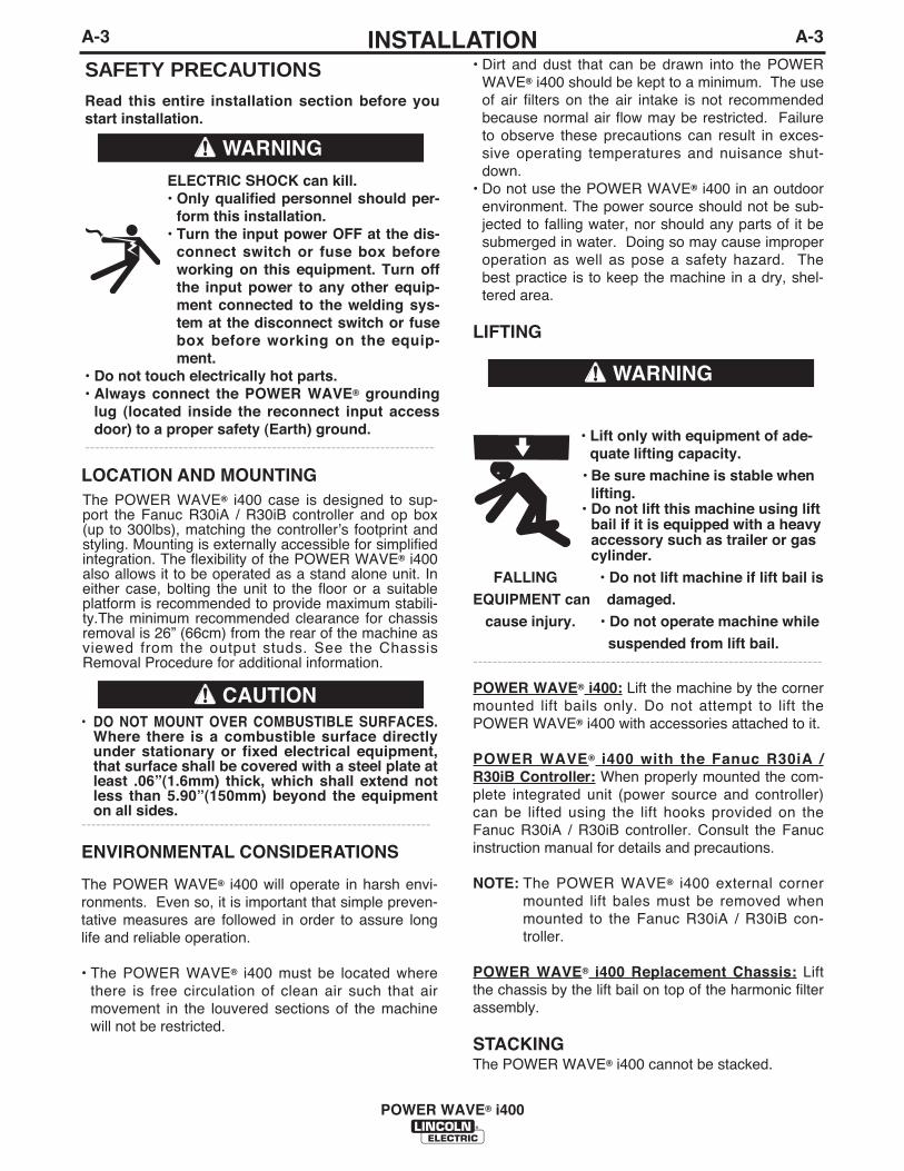
SAFETY PRECAUTIONSRead this entire installation section before youstart installation.
ELECTRIC SHOCK can kill.• Only qualified personnel should per-
form this installation.• Turn the input power OFF at the dis-
connect switch or fuse box beforeworking on this equipment. Turn offthe input power to any other equip-ment connected to the welding sys-tem at the disconnect switch or fusebox before working on the equip-ment.
• Do not touch electrically hot parts.• Always connect the POWER WAVE® grounding
lug (located inside the reconnect input accessdoor) to a proper safety (Earth) ground.
-----------------------------------------------------------------------
WARNING
CAUTION
• Dirt and dust that can be drawn into the POWERWAVE® i400 should be kept to a minimum. The useof air filters on the air intake is not recommendedbecause normal air flow may be restricted. Failureto observe these precautions can result in exces-sive operating temperatures and nuisance shut-down.
• Do not use the POWER WAVE® i400 in an outdoorenvironment. The power source should not be sub-jected to falling water, nor should any parts of it besubmerged in water. Doing so may cause improperoperation as well as pose a safety hazard. Thebest practice is to keep the machine in a dry, shel-tered area.
LIFTING
• Lift only with equipment of ade-quate lifting capacity.
• Be sure machine is stable whenlifting.
• Do not lift this machine using liftbail if it is equipped with a heavyaccessory such as trailer or gascylinder.
FALLING • Do not lift machine if lift bail is
EQUIPMENT can damaged.
cause injury. • Do not operate machine while
suspended from lift bail.-----------------------------------------------------------------------
POWER WAVE® i400: Lift the machine by the cornermounted lift bails only. Do not attempt to lift thePOWER WAVE® i400 with accessories attached to it.
POWER WAVE® i400 with the Fanuc R30iA /R30iB Controller: When properly mounted the com-plete integrated unit (power source and controller)can be lifted using the lift hooks provided on theFanuc R30iA / R30iB controller. Consult the Fanucinstruction manual for details and precautions.
NOTE: The POWER WAVE® i400 external cornermounted lift bales must be removed whenmounted to the Fanuc R30iA / R30iB con-troller.
POWER WAVE® i400 Replacement Chassis: Liftthe chassis by the lift bail on top of the harmonic filterassembly.
STACKINGThe POWER WAVE® i400 cannot be stacked.
WARNING
A-4INSTALLATION
POWER WAVE® i400
A-4
ELECTROMAGNETIC COMPATIBILITY (EMC)
The EMC classification of the POWER WAVE® i400 isIndustrial, Scientific and Medical (ISM) group 2, class A. ThePOWER WAVE® i400 is for industrial use only. (See printsL10093-1, -2 Safety Pages in the front of Instruction Manualfor further details).
Locate the POWER WAVE® i400 away from radio controlledmachinery. The normal operation of the POWER WAVE®
i400 may adversely affect the operation of RF controlledequipment, which may result in bodily injury or damage tothe equipment.
INPUT AND GROUNDING CONNECTIONS
MACHINE GROUNDING
The frame of the welder must be grounded. A ground termi-nal marked with the symbol shown is located inside thereconnect/input access door for this purpose. See yourlocal and national electrical codes for proper groundingmethods.
INPUT CONNECTIONS
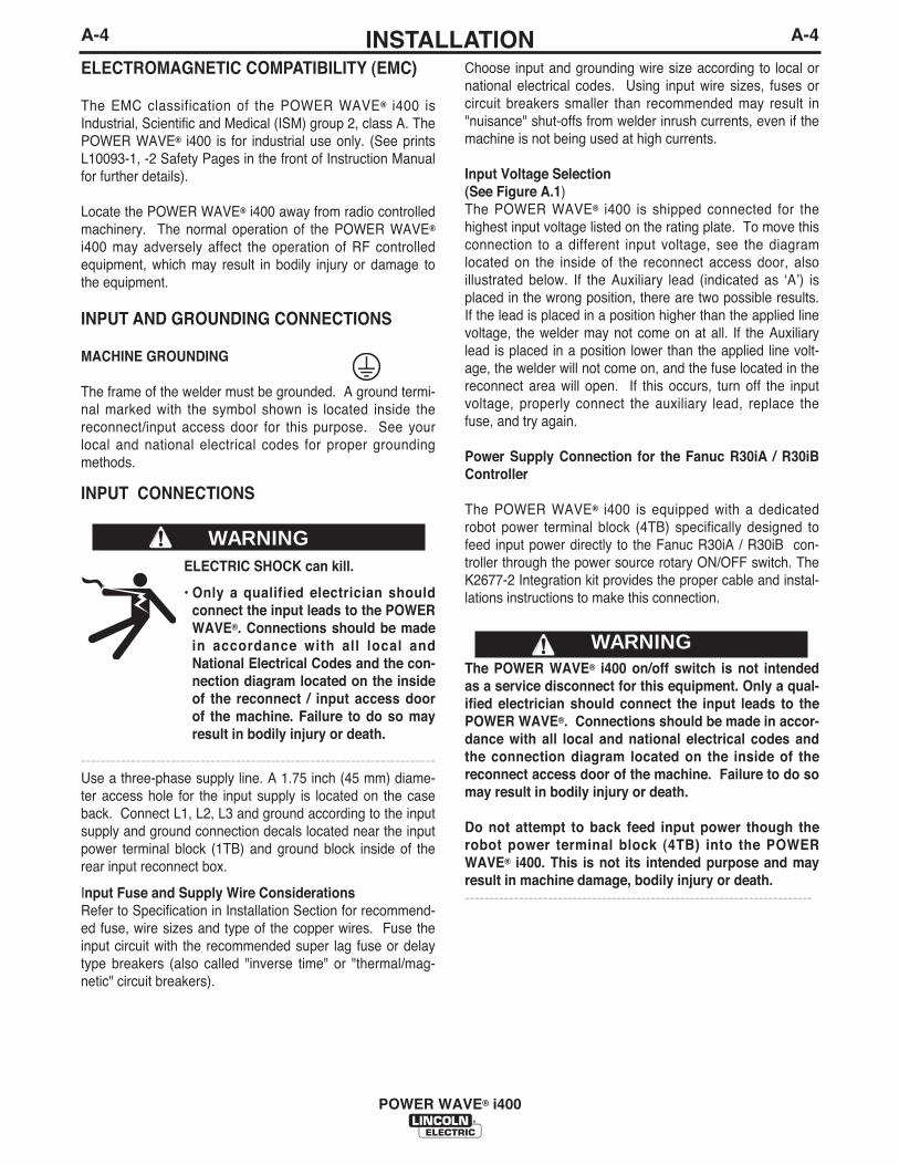
ELECTRIC SHOCK can kill.
• Only a qualified electrician shouldconnect the input leads to the POWERWAVE®. Connections should be madein accordance with all local andNational Electrical Codes and the con-nection diagram located on the insideof the reconnect / input access doorof the machine. Failure to do so mayresult in bodily injury or death.
-----------------------------------------------------------------------Use a three-phase supply line. A 1.75 inch (45 mm) diame-ter access hole for the input supply is located on the caseback. Connect L1, L2, L3 and ground according to the inputsupply and ground connection decals located near the inputpower terminal block (1TB) and ground block inside of therear input reconnect box.
Input Fuse and Supply Wire ConsiderationsRefer to Specification in Installation Section for recommend-ed fuse, wire sizes and type of the copper wires. Fuse theinput circuit with the recommended super lag fuse or delaytype breakers (also called "inverse time" or "thermal/mag-netic" circuit breakers).
Choose input and grounding wire size according to local ornational electrical codes. Using input wire sizes, fuses orcircuit breakers smaller than recommended may result in"nuisance" shut-offs from welder inrush currents, even if themachine is not being used at high currents.
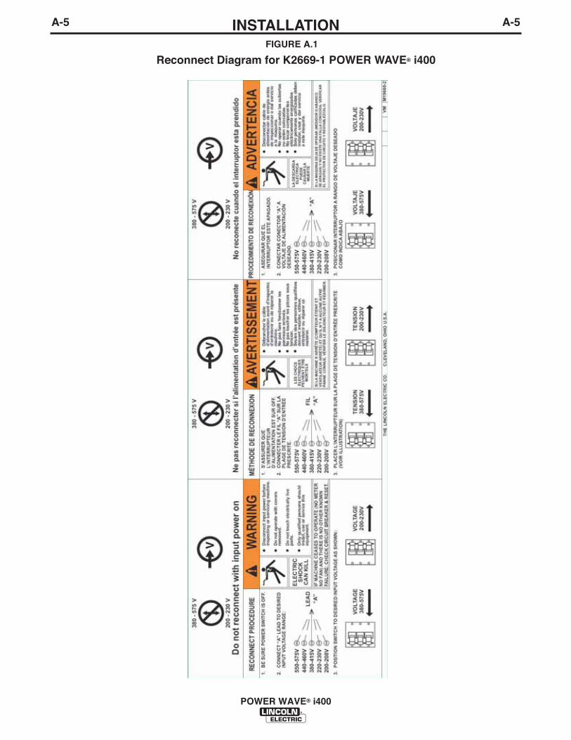
Input Voltage Selection (See Figure A.1)The POWER WAVE® i400 is shipped connected for thehighest input voltage listed on the rating plate. To move thisconnection to a different input voltage, see the diagramlocated on the inside of the reconnect access door, alsoillustrated below. If the Auxiliary lead (indicated as ʻAʼ) isplaced in the wrong position, there are two possible results.If the lead is placed in a position higher than the applied linevoltage, the welder may not come on at all. If the Auxiliarylead is placed in a position lower than the applied line volt-age, the welder will not come on, and the fuse located in thereconnect area will open. If this occurs, turn off the inputvoltage, properly connect the auxiliary lead, replace thefuse, and try again.
Power Supply Connection for the Fanuc R30iA / R30iBController
The POWER WAVE® i400 is equipped with a dedicatedrobot power terminal block (4TB) specifically designed tofeed input power directly to the Fanuc R30iA / R30iB con-troller through the power source rotary ON/OFF switch. TheK2677-2 Integration kit provides the proper cable and instal-lations instructions to make this connection.
The POWER WAVE® i400 on/off switch is not intendedas a service disconnect for this equipment. Only a qual-ified electrician should connect the input leads to thePOWER WAVE®. Connections should be made in accor-dance with all local and national electrical codes andthe connection diagram located on the inside of thereconnect access door of the machine. Failure to do somay result in bodily injury or death.
Do not attempt to back feed input power though therobot power terminal block (4TB) into the POWERWAVE® i400. This is not its intended purpose and mayresult in machine damage, bodily injury or death. -----------------------------------------------------------------------
WARNING
WARNING
A-5INSTALLATION
POWER WAVE® i400
A-5
Reconnect Diagram for K2669-1 POWER WAVE® i400FIGURE A.1
A-6INSTALLATION
POWER WAVE® i400
A-6
SystemIdentifier
Power Source
Integration Kit
Wire Drive
Power Sourceto Wire DriveControl Cable
Weld Cables
Robot ArmRobot Controller
Torch
Part No.
K2669-1
K2677-2
K2685-1
K1785-xx1
K2163-xx-or-
K1842-xx
KxxxxKxxxxKxxxx
Description
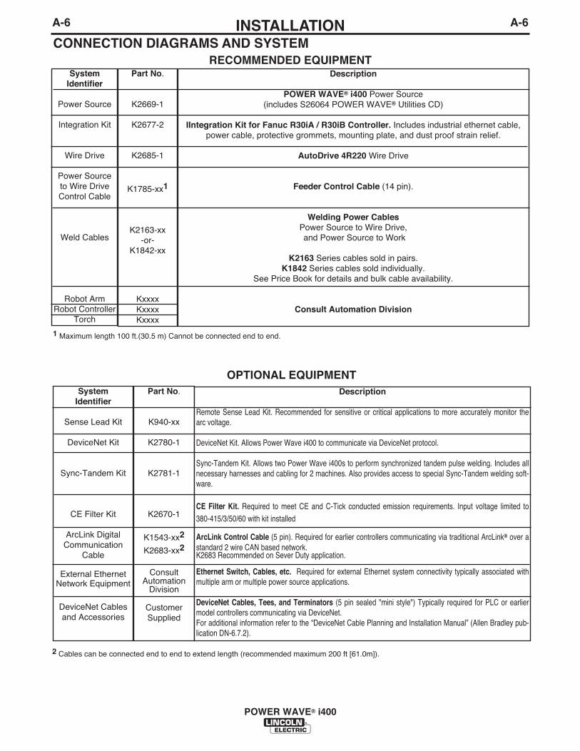
POWER WAVE® i400 Power Source(includes S26064 POWER WAVE® Utilities CD)
IIntegration Kit for Fanuc R30iA / R30iB Controller. Includes industrial ethernet cable,power cable, protective grommets, mounting plate, and dust proof strain relief.
AutoDrive 4R220 Wire Drive
Feeder Control Cable (14 pin).
Welding Power CablesPower Source to Wire Drive,and Power Source to Work
K2163 Series cables sold in pairs.K1842 Series cables sold individually.
See Price Book for details and bulk cable availability.
Consult Automation Division
RECOMMENDED EQUIPMENTCONNECTION DIAGRAMS AND SYSTEM
SystemIdentifier
Sense Lead Kit
DeviceNet Kit
Sync-Tandem Kit
CE Filter Kit
ArcLink DigitalCommunication
Cable
External EthernetNetwork Equipment
DeviceNet Cablesand Accessories
Part No.
K940-xx
K2780-1
K2781-1
K2670-1
K1543-xx2
K2683-xx2
ConsultAutomation
Division
CustomerSupplied
Description
Remote Sense Lead Kit. Recommended for sensitive or critical applications to more accurately monitor thearc voltage.
DeviceNet Kit. Allows Power Wave i400 to communicate via DeviceNet protocol.
Sync-Tandem Kit. Allows two Power Wave i400s to perform synchronized tandem pulse welding. Includes allnecessary harnesses and cabling for 2 machines. Also provides access to special Sync-Tandem welding soft-ware.
CE Filter Kit. Required to meet CE and C-Tick conducted emission requirements. Input voltage limited to380-415/3/50/60 with kit installed
ArcLink Control Cable (5 pin). Required for earlier controllers communicating via traditional ArcLink® over astandard 2 wire CAN based network.K2683 Recommended on Sever Duty application.
Ethernet Switch, Cables, etc. Required for external Ethernet system connectivity typically associated withmultiple arm or multiple power source applications.
DeviceNet Cables, Tees, and Terminators (5 pin sealed "mini style") Typically required for PLC or earliermodel controllers communicating via DeviceNet.For additional information refer to the “DeviceNet Cable Planning and Installation Manual” (Allen Bradley pub-lication DN-6.7.2).
OPTIONAL EQUIPMENT
1 Maximum length 100 ft.(30.5 m) Cannot be connected end to end.
2 Cables can be connected end to end to extend length (recommended maximum 200 ft [61.0m]).
A-7INSTALLATION
POWER WAVE® i400
A-7
SystemIdentifier
Coaxial Weld Cable
External DressCable for Robot
Arm
Personal Computer
ReplacementChassis
Part No.
K1796-xx
K2593-xx
K2709-xx
CustomerSupplied
K2673-1
Description
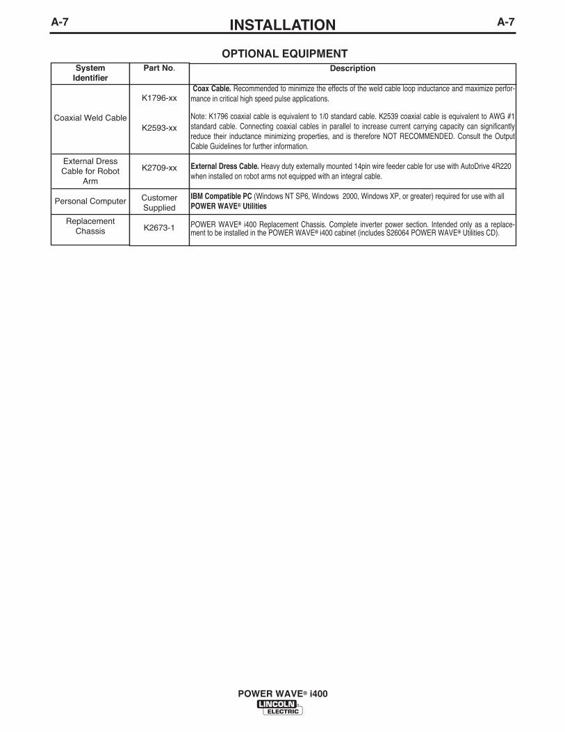
Coax Cable. Recommended to minimize the effects of the weld cable loop inductance and maximize perfor-mance in critical high speed pulse applications.
Note: K1796 coaxial cable is equivalent to 1/0 standard cable. K2539 coaxial cable is equivalent to AWG #1standard cable. Connecting coaxial cables in parallel to increase current carrying capacity can significantlyreduce their inductance minimizing properties, and is therefore NOT RECOMMENDED. Consult the OutputCable Guidelines for further information.
External Dress Cable. Heavy duty externally mounted 14pin wire feeder cable for use with AutoDrive 4R220when installed on robot arms not equipped with an integral cable.
IBM Compatible PC (Windows NT SP6, Windows 2000, Windows XP, or greater) required for use with allPOWER WAVE® Utilities
POWER WAVE® i400 Replacement Chassis. Complete inverter power section. Intended only as a replace-ment to be installed in the POWER WAVE® i400 cabinet (includes S26064 POWER WAVE® Utilities CD).
OPTIONAL EQUIPMENT
A-8INSTALLATION
POWER WAVE® i400
A-8
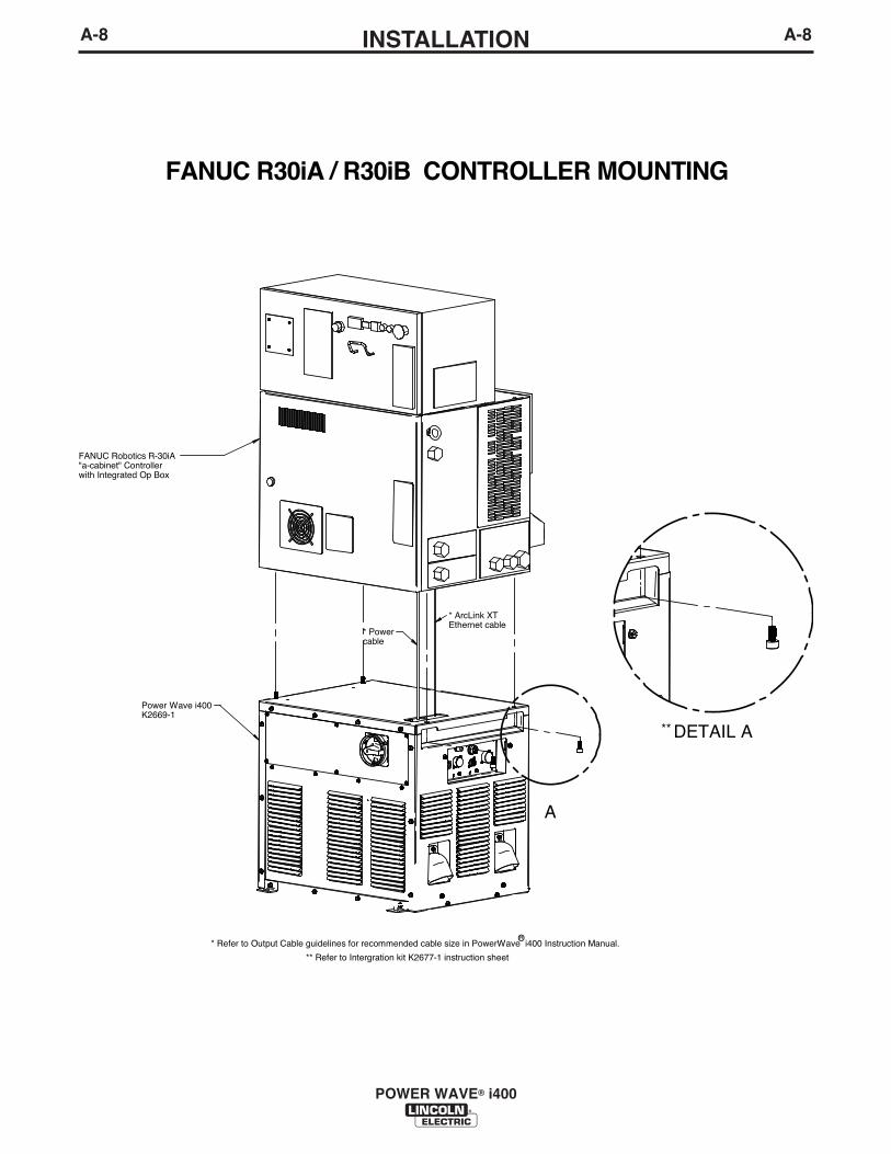
FANUC R30iA / R30iB CONTROLLER MOUNTING
FANUC Robotics R-30iA "a-cabinet" Controller with Integrated Op Box
Power Wave i400K2669-1
* ArcLink XTEthernet cable
* Powercable
DETAIL A
A
* Refer to Output Cable guidelines for recommended cable size in PowerWave i400 Instruction Manual.
** Refer to Intergration kit K2677-1 instruction sheet
**
OR
A-9INSTALLATION
POWER WAVE® i400
A-9
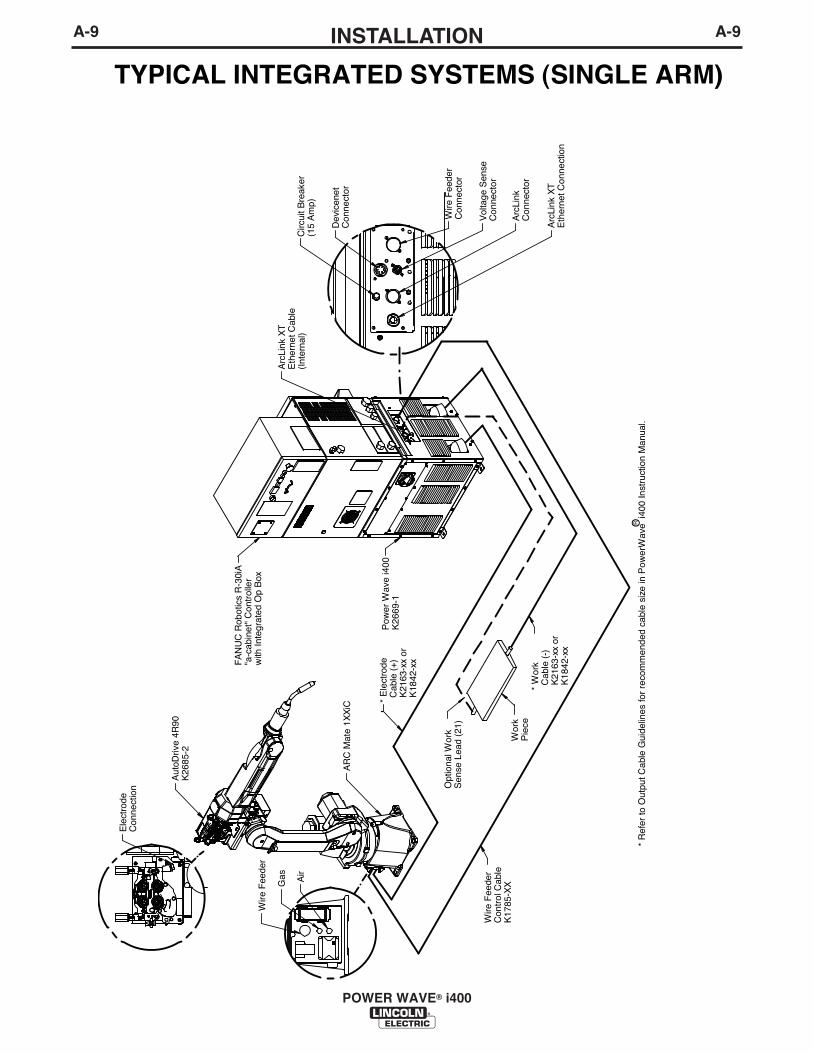
TYPICAL INTEGRATED SYSTEMS (SINGLE ARM)
Arc
Link
XT
Eth
erne
t Con
nect
ion
Vol
tage
Sen
seC
onne
ctor
Wire
Fee
der
Con
nect
or
Pow
er W
ave
i400
K26
69-1
Opt
iona
l Wor
kS
ense
Lea
d (2
1)
Wire
Fee
der
Con
trol
Cab
leK
1785
-XX
Arc
Link
XT
Eth
erne
t Cab
le(I
nter
nal)
* E
lect
rode
Cab
le (
+) K
2163
-xx
or K
1842
-xx
* R
efer
to O
utpu
t Cab
le G
uide
lines
for
reco
mm
ende
d ca
ble
size
in P
ower
Wav
e i4
00 In
stru
ctio
n M
anua
l.
Wire
Fee
der
Gas
Ele
ctro
deC
onne
ctio
n
AR
C M
ate
1XX
iC
Wor
k P
iece
FA
NU
C R
obot
ics
R-3
0iA
"a-c
abin
et"
Con
trol
ler
with
Inte
grat
ed O
p B
ox
Air
* W
ork
Cab
le (
-) K
2163
-xx
or K
1842
-xx
Arc
Link
Con
nect
or
Dev
icen
etC
onne
ctor
Circ
uit B
reak
er(1
5 A
mp)
R O
Aut
oDriv
e 4R
90K
2685
-2
A-10INSTALLATION
POWER WAVE® i400
A-10
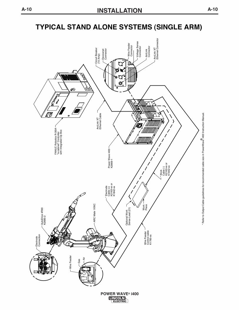
TYPICAL STAND ALONE SYSTEMS (SINGLE ARM)
Dev
icen
etC
onne
ctor
Wire
Fee
der
Con
nect
or
Circ
uit B
reak
er(1
5 A
mp)
Arc
Link
XT
Eth
erne
t Con
nect
or
Vol
tage
Sen
seC
onne
ctor
Arc
Link
Con
nect
or
Arc
Link
XT
Eth
erne
t Cab
le
FA
NU
C R
obot
ics
R-3
0iA
"a-c
abin
et"
Con
trol
ler
with
Inte
grat
ed O
p B
ox
Pow
er W
ave
i400
K26
69-1
* E
lect
rode
Cab
le (
+) K
2163
-xx
or K
1842
-xx
* W
ork
Cab
le (
-) K
2163
-xx
or K
1842
-xx
Opt
iona
l Wor
kS
ense
Lea
d (2
1) Wor
kP
iece
Wire
Fee
der
Con
trol
cab
leK
1785
-xx
AR
C M
ate
1XX
iC
Wire
Fee
der
Gas A
ir
Ele
ctro
de
Con
nect
ion
* R
efer
to O
utpu
t Cab
le g
uide
lines
for
reco
mm
ende
d ca
ble
size
in P
ower
Wav
e i4
00 In
stru
ctio
n M
anua
l.R O
Aut
oDriv
e 4R
90K
2685
-2
A-11INSTALLATION
POWER WAVE® i400
A-11
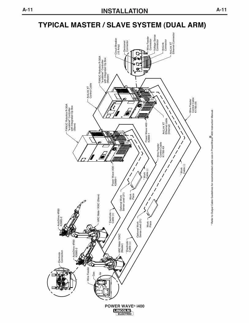
TYPICAL MASTER / SLAVE SYSTEM (DUAL ARM)
FA
NU
C R
obot
ics
R-3
0iA
"a
-cab
inet"
Con
trol
ler
with
Inte
grat
ed O
p B
ox(M
aste
r)
FA
NU
C R
obot
ics
R-3
0iA
"a
-cab
inet"
Con
trol
ler
with
Inte
grat
ed O
p B
ox(S
lave
)
Opt
iona
l Wor
kS
ense
Lea
d (2
1)
Opt
iona
l Wor
kS
ense
Lea
d (2
1)
* W
ork
Cab
le (
-)
* W
ork
Cab
le (
-)
Wire
Fee
der
Con
trol
Cab
leK
1785
-XX
Wire
Fee
der
Con
trol
Cab
leK
1785
-XX
Arc
Link
XT
Con
trol
Cab
le
* E
lect
rode
Cab
le (
+)
* E
lect
rode
Cab
le (
+)
Arc
Link
XT
Eth
erne
t cab
le(I
nter
nal)
* R
efer
to O
utpu
t Cab
le G
uide
lines
for
reco
mm
ende
d ca
ble
size
in P
ower
Wav
e i4
00 In
stru
ctio
n M
anua
l.
Ele
ctro
deC
onne
ctio
n
Gas Air
Vol
tage
Sen
seC
onne
ctor
Wire
Fee
der
Con
nect
or
Pow
er W
ave
i400
K26
69-1
Pow
er W
ave
i400
K26
69-1
AR
C M
ate
1XX
iC(M
aste
r)
AR
C M
ate
1XX
iC (
Sla
ve)
Wor
k P
iece
Wor
k P
iece
Aut
oDriv
e 4R
90K
2685
-2
Aut
oDriv
e 4R
90K
2685
-2
Wire
Fee
der
Arc
Link
Con
nect
or
Arc
Link
XT
Eth
erne
t Con
nect
or
Dev
icen
etC
onne
ctor
Circ
uit B
reak
er(1
5 A
mp)
R O
A-12INSTALLATION
POWER WAVE® i400
A-12
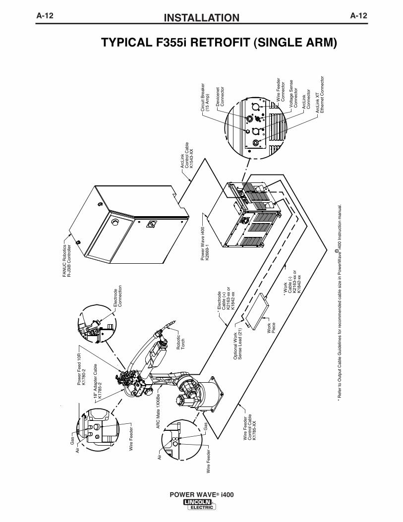
TYPICAL F355i RETROFIT (SINGLE ARM)
Pow
er W
ave
i400
K26
69-1
FA
NU
C R
obot
ics
R-J
3iB
Con
trol
ler
* E
lect
rode
Cab
le (
+) K
2163
-xx
or K
1842
-xx
Opt
iona
l Wor
kS
ense
Lea
d (2
1)W
ire F
eede
rC
ontr
ol C
able
K17
85-X
X
Arc
Link
Con
trol
Cab
leK
1543
-XX
* R
efer
to O
utpu
t Cab
le G
uide
lines
for
reco
mm
ende
d ca
ble
size
in P
ower
Wav
e i4
00 In
stru
ctio
n m
anua
l.
Rob
otic
Tor
ch
AR
C M
ate
1XX
iBe
Pow
er F
eed
10R
K17
80-2
18"
Ada
pter
Cab
le
K17
85-2
Wire
Fee
der
Ele
ctro
deC
onne
ctio
n
Air
Gas
Wire
Fee
der
Gas
Air
* W
ork
Cab
le (
-) K
2163
-xx
or K
1842
-xx
Wor
k P
iece
Circ
uit B
reak
er(1
5 A
mp)
Dev
icen
etC
onne
ctor
Wire
Fee
der
Con
nect
or
Vol
tage
Sen
seC
onne
ctor
Arc
Link
Con
nect
or
Arc
Link
XT
Eth
erne
t Con
nect
or
R O

GENERAL GUIDELINES
• Select the appropriate size cables per the“Output Cable Guidelines” in Table A.1.Excessive voltage drops caused by undersizedwelding cables and poor connections often result inunsatisfactory welding performance. Always use thelargest welding cables (electrode and work) that arepractical, and be sure all connections are clean andtight.
Note: Excessive heat in the weld circuit indicatesundersized cables and/or bad connections.
• Route all cables directly to the work and wirefeeder, avoid excessive lengths and do not coilexcess cable. Route the electrode and work cablesin close proximity to one another to minimize theloop area and therefore the inductance of the weldcircuit.
• Always weld in a direction away from the work(ground) connection.
In Table A.1 are copper cable sizes recommended fordifferent currents and duty cycles. Lengths stipulatedare the distance from the welder to work and back tothe welder again. Cable sizes are increased forgreater lengths primarily for the purpose of minimizingcable drop.
A-13INSTALLATION
POWER WAVE® i400
A-13
ELECTRODE AND WORK CONNECTIONS
Connect the electrode and work cables between theappropriate output studs of the POWER WAVE® i400and the robot weld cell per the connection diagramsincluded in this document. Size and route the cablesper the following.
• Most welding applications run with the electrodebeing positive (+). For those applications, connectthe electrode cable between the wire drive feed plateand the positive (+) output stud on the power source.Connect a work lead from the negative (-) powersource output stud to the work piece.
• When negative electrode polarity is required, suchas in some Innershield applications, reverse the out-put connections at the power source (electrode cableto the negative (-) stud, and work cable to the posi-tive (+) stud).
Negative electrode polarity operation WITHOUTuse of a remote work sense lead (21) requires theNegative Electrode Polarity attribute to be set. Seethe Remote Sense Lead Specification section ofthis document for further details.
For additional Safety information regarding the elec-trode and work cable set-up, See the standard “SAFE-TY INFORMATION” located in the front of thisInstruction Manual.
CAUTION
OUTPUT CABLE GUIDELINESTABLE A.1
CABLE SIZES FOR COMBINED LENGTHS OF ELECTRODE AND WORK CABLES(RUBBER COVERED COPPER - RATED 75°C)**
PercentDutyCycle
6010020
40 & 3030406010060100606010060
22
4 or 5332111
2/01/02/03/02/0
223332111
2/01/02/03/02/0
222221111
2/02/02/03/03/0
11111111
1/02/02/03/03/03/0
1/01/01/01/01/01/01/01/02/03/03/04/04/04/0
200200225225250250250250300325350400400500
Amperes
0 to 50 Ft. 50 to 100 Ft. 100 to 150 Ft. 150 to 200 Ft. 200 to 250 Ft.
** Tabled values are for operation at ambient temperatures of 40°C and below. Applications above 40°C may require cables larger thanrecommended, or cables rated higher than 75°C.
A-14INSTALLATION
POWER WAVE® i400
A-14
General Guidelines for Voltage Sense Leads
Sense leads should be attached as close to the weldas practical, and out of the weld current path whenpossible. In extremely sensitive applications it may benecessary to route cables that contain the senseleads away from the electrode and work weldingcables.
Voltage sense leads requirements are based on theweld process as follows:
TABLE A.2Process Electrode Voltage Work Voltage
Sensing (67 lead) 1 Sensing (21 lead) 2
GMAW 67 lead required 21 lead optional 3
GMAW-P 67 lead required 21 lead optional 3
FCAW 67 lead required 21 lead optional 3
GTAW Voltage sense at studs Voltage sense at studs
1 The electrode voltage sense lead (67) is automatically enabledby the weld process, and integral to the to the 14 pin wire feedercontrol cable (K1785).
2 The work voltage sense lead (21) is manually enabled, but over-ridden by constant current weld processes defined for stud sens-ing.
3 Negative polarity semi-automatic process operation WITHOUTuse of a remote work sense lead (21) requires the NegativeElectrode Polarity attribute to be set. This establishes which out-put stud the electrode voltage sense lead (67) will be referencedto.
Electrode Voltage Sensing
The remote ELECTRODE sense lead (67) is built intothe standard wire feeder control cable (K1785) and isalways connected to the wire drive feed plate when awire feeder is present. Enabling or disabling electrodevoltage sensing is application specific, and automati-cally configured by the active weld mode.
The remote ELECTRODE sense lead (67) is alsoavailable in the remote Voltage Sense Connector forapplications that do not use the standard wire feedercontrol cable (K1785). This can be easily accessedwith the optional K940 Sense Lead kit.
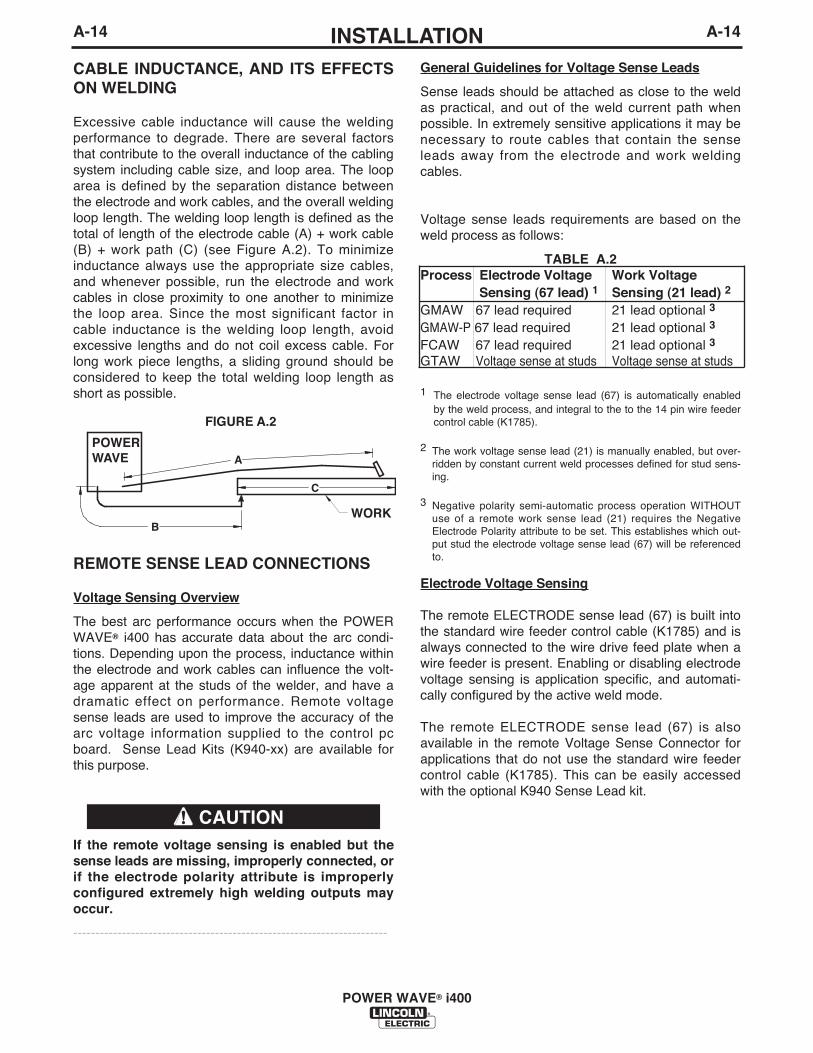
CABLE INDUCTANCE, AND ITS EFFECTSON WELDING
Excessive cable inductance will cause the weldingperformance to degrade. There are several factorsthat contribute to the overall inductance of the cablingsystem including cable size, and loop area. The looparea is defined by the separation distance betweenthe electrode and work cables, and the overall weldingloop length. The welding loop length is defined as thetotal of length of the electrode cable (A) + work cable(B) + work path (C) (see Figure A.2). To minimizeinductance always use the appropriate size cables,and whenever possible, run the electrode and workcables in close proximity to one another to minimizethe loop area. Since the most significant factor incable inductance is the welding loop length, avoidexcessive lengths and do not coil excess cable. Forlong work piece lengths, a sliding ground should beconsidered to keep the total welding loop length asshort as possible.
REMOTE SENSE LEAD CONNECTIONS
Voltage Sensing Overview
The best arc performance occurs when the POWERWAVE® i400 has accurate data about the arc condi-tions. Depending upon the process, inductance withinthe electrode and work cables can influence the volt-age apparent at the studs of the welder, and have adramatic effect on performance. Remote voltagesense leads are used to improve the accuracy of thearc voltage information supplied to the control pcboard. Sense Lead Kits (K940-xx) are available forthis purpose.
If the remote voltage sensing is enabled but thesense leads are missing, improperly connected, orif the electrode polarity attribute is improperlyconfigured extremely high welding outputs mayoccur.
-----------------------------------------------------------------------
CAUTION
B
A
C
POWER WAVE
FIGURE A.2
WORK
If a remote work voltage sense lead is used, itmust be enabled through the Fanuc TeachPendant or with the Weld Manager Utility (includ-ed on the Power Wave Utilities and ServiceNavigator CDʼs or available at www.power-wavesoftware.com).-----------------------------------------------------------------------
Voltage Sensing Considerations for Multiple ArcSystemsSpecial care must be taken when more than one arcis welding simultaneously on a single part. Multiplearc applications do not necessarily dictate the use ofremote work voltage sense leads, but they are strong-ly recommended.
If Sense Leads ARE NOT Used:• Avoid common current paths. Current from adja-
cent arcs can induce voltage into each others cur-rent paths that can be misinterpreted by the powersources, and result in arc interference.
If Sense Leads ARE Used:• Position the sense leads out of the path of the
weld current. Especially any current paths com-mon to adjacent arcs. Current from adjacent arcscan induce voltage into each others current pathsthat can be misinterpreted by the power sources,and result in arc interference.
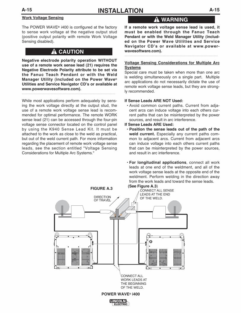
• For longitudinal applications, connect all workleads at one end of the weldment, and all of thework voltage sense leads at the opposite end of theweldment. Perform welding in the direction awayfrom the work leads and toward the sense leads.
(See Figure A.3)
A-15INSTALLATION
POWER WAVE® i400
A-15
Work Voltage Sensing
The POWER WAVE® i400 is configured at the factoryto sense work voltage at the negative output stud(positive output polarity with remote Work VoltageSensing disabled).
Negative electrode polarity operation WITHOUTuse of a remote work sense lead (21) requires theNegative Electrode Polarity attribute to be set viathe Fanuc Teach Pendant or with the WeldManager Utility (included on the Power Wave®
Utilities and Service Navigator CDʼs or available atwww.powerwavesoftware.com).-----------------------------------------------------------------------
While most applications perform adequately by sens-ing the work voltage directly at the output stud, theuse of a remote work voltage sense lead is recom-mended for optimal performance. The remote WORKsense lead (21) can be accessed through the four-pinvoltage sense connector located on the control panelby using the K940 Sense Lead Kit. It must beattached to the work as close to the weld as practical,but out of the weld current path. For more informationregarding the placement of remote work voltage senseleads, see the section entitled "Voltage SensingConsiderations for Multiple Arc Systems."
WARNING
CAUTION
DIRECTIONOF TRAVEL
CONNECT ALLWORK LEADS AT THE BEGINNINGOF THE WELD.
CONNECT ALL SENSELEADS AT THE ENDOF THE WELD.
FIGURE A.3
A-16INSTALLATION
POWER WAVE® i400
A-16
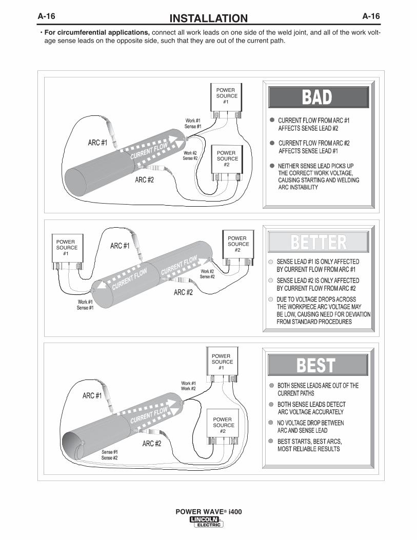
• For circumferential applications, connect all work leads on one side of the weld joint, and all of the work volt-age sense leads on the opposite side, such that they are out of the current path.
POWERSOURCE #2
POWERSOURCE #1
POWERSOURCE #1
POWERSOURCE #2
POWERSOURCE #2
POWERSOURCE #1
A-17INSTALLATION
POWER WAVE® i400
A-17
CONTROL CABLE CONNECTIONS
General Guidelines
Genuine Lincoln control cables should be used at alltimes (except where noted otherwise). Lincoln cablesare specifically designed for the communication andpower needs of the POWER WAVE® / Power Feed sys-tems. Most are designed to be connected end to end forease of extension. Generally, it is recommended that thetotal length not exceed 100 ft. (30.5 m). The use of non-standard cables, especially in lengths greater than 25 ft.(7.6 m), can lead to communication problems (systemshutdowns), poor motor acceleration (poor arc starting),and low wire driving force (wire feeding problems).Always use the shortest length of control cable possible,and DO NOT coil excess cable.
Regarding cable placement, best results will beobtained when control cables are routed separatefrom the weld cables. This minimizes the possibilityof interference between the high currents flowingthrough the weld cables, and the low level signals inthe control cables. These recommendations apply toall communication cables including ArcLink® andEthernet connections.-----------------------------------------------------------------------
COMMON EQUIPMENT CONNECTIONS
Connection Between Power Source and Wire Feeder(K1785 or K2709 Control Cable)The 14 pin wire feeder control cable connects the powersource to the wire drive. It contains all of the necessarysignals to drive the motor and monitor the arc, includingthe motor power, tachometer, and arc voltage feedbacksignals. The wire feeder connection on the POWERWAVE® i400 is located on the recessed control panelabove the output studs. Fanuc robot arms are equippedwith internal cabling and provide a standard 14 pin MS-style connection at the base of the robot, and near thewire feeder mount at the top of the arm. The K2709series external dress cable is recommended for severeduty applications such as hard automation or for robotarms not equipped with an internal control cable. Bestresults will be obtained when control cables are routedseparate from the weld cables, especially in long dis-tance applications. Maximum cable length should notexceed 100ft(30.5m).
Connection Between Power Source and ArcLink®XTCompatible Controllers or Ethernet Networks. Newermodel controllers, such as the Fanuc R30iA / R30iB, com-municate via ArcLink®XT over an industrial Ethernet connec-tion. To facilitate this, the Power Wave i400 is equipped withan IP67 rated ODVA compliant RJ-45 Ethernet connector,which is located on the recessed control panel above theoutput studs. A special access chute is provided above theEthernet connection on the Power Wave i400 to accommo-date seamless integration with the Fanuc R30iA / R30iBcontroller. The K2677-2 Integration Kit includes a speciallydesigned industrial rated Ethernet cable for this purpose.
It is highly recommended that all external Ethernet equip-ment (cables, switches, etc.), as defined by the connectiondiagrams, be obtained through the Lincoln ElectricAutomation Division. It is critical that all Ethernet cablesexternal to either a conduit or an enclosure are solid con-ductor, shielded cat 5e cable, with a drain. The drain shouldbe grounded at the source of transmission, such as a net-work switch or the Fanuc R30iA / R30iB ground strip.Ethernet cables will achieve optimal performance levels atdistances up to 25 feet. Special attention to layout may berequired to support distances greater than 25 feet, includingspecialized network equipment. For best results, alwaysroute Ethernet cables away from weld cables, wire drivecontrol cables, or any other current carrying device that cancreate a fluctuating magnetic field. For additional guidelinesrefer to industry standard documents for industrial Ethernetnetworks. Failure to follow these recommendations canresult in an Ethernet connection failure during welding.
The ethernet port of the Power Wave i400 is factory config-ured with a dynamic IP address. This is required for seam-less operation with the Fanuc R30iA / R30iB controller.
Connection Between Power Source and ArcLink®
Compatible Controllers (K1543 or K2683 ArcLinkControl Cable)
Earlier model Fanuc controllers communicate via traditionalArcLink® over a standard 2 wire CAN based network. Inthese systems, the 5 pin ArcLink control cable connects thepower source to the controller.
The control cable consists of two power leads, one twistedpair for digital communication, and one lead for voltagesensing. The sense leads and power leads are typicallyunused in this application. The 5 pin ArcLink connection onthe POWER WAVE® i400 is located on the recessed controlpanel above the output studs. The control cable is keyedand polarized to prevent improper connection. Best resultswill be obtained when control cables are routed separatefrom the weld cables, especially in long distance applica-tions. The recommended combined length of the ArcLinkcontrol cable network should not exceed 200ft(61.0m).
CAUTION

A-18INSTALLATION
POWER WAVE® i400
A-18
Connections Between Power Source and OptionalDeviceNet PLC Controller. Hard Automation applica-tions and some earlier model controllers may requireDeviceNet connectivity to control the power source.DeviceNet can also be used to monitor welding data,and system status information. The optional K2780-1DeviceNet Kit is available for this purpose. It includesa 5 pin DeviceNet sealed mini style receptacle thatmounts on the recessed control panel of the PowerWave i400, above the output studs. The DeviceNetcable is keyed and polarized to prevent improper con-nection. For best results, route DeviceNet cablesaway from weld cables, wire drive control cables, orany other current carrying device that can create afluctuating magnetic field. DeviceNet cables must besourced locally by the customer. For additional guide-lines refer to the “DeviceNet Cable Planning andInstallation Manual” (Allen Bradley publication DN-6.7.2).
The DeviceNet MAC ID and baud rate of the POWERWAVE® i400 can be configured with the DiagnosticsUtility (included on the POWER WAVE® Utilities andService Navigator CDʼs or available at www.power-wavesoftware.com).
OTHER SET-UP ISSUES
Selecting a Wire Drive and Setting the Wire DriveGear Ratio. The POWER WAVE® i400 can accommo-date a number of standard wire drives including theAutoDrive 4R220 (default) and PF-10R. The feedercontrol system must be configured for both the wiredrive type and gear ratio (high or low speed range).This can be accomplished via the Fanuc TeachPendant (V7.30p14 or later) or with the WeldManager Utility (included on the Power Wave® Utilitiesand Service Navigator CDʼs or available at www.pow-erwavesoftware.com).
Additional information is also available in the “How To”section at www.powerwavesoftware.com.
B-1OPERATIONB-1
POWER WAVE® i400
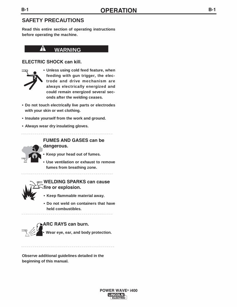
SAFETY PRECAUTIONS
Read this entire section of operating instructionsbefore operating the machine.
ELECTRIC SHOCK can kill.
• Unless using cold feed feature, whenfeeding with gun trigger, the elec-trode and drive mechanism arealways electrically energized andcould remain energized several sec-onds after the welding ceases.
• Do not touch electrically live parts or electrodeswith your skin or wet clothing.
• Insulate yourself from the work and ground.
• Always wear dry insulating gloves.
FUMES AND GASES can bedangerous.
• Keep your head out of fumes.
• Use ventilation or exhaust to removefumes from breathing zone.
WELDING SPARKS can causefire or explosion.
• Keep flammable material away.
• Do not weld on containers that haveheld combustibles.
ARC RAYS can burn.
• Wear eye, ear, and body protection.
Observe additional guidelines detailed in thebeginning of this manual.
WARNING
B-2OPERATIONB-2
POWER WAVE® i400
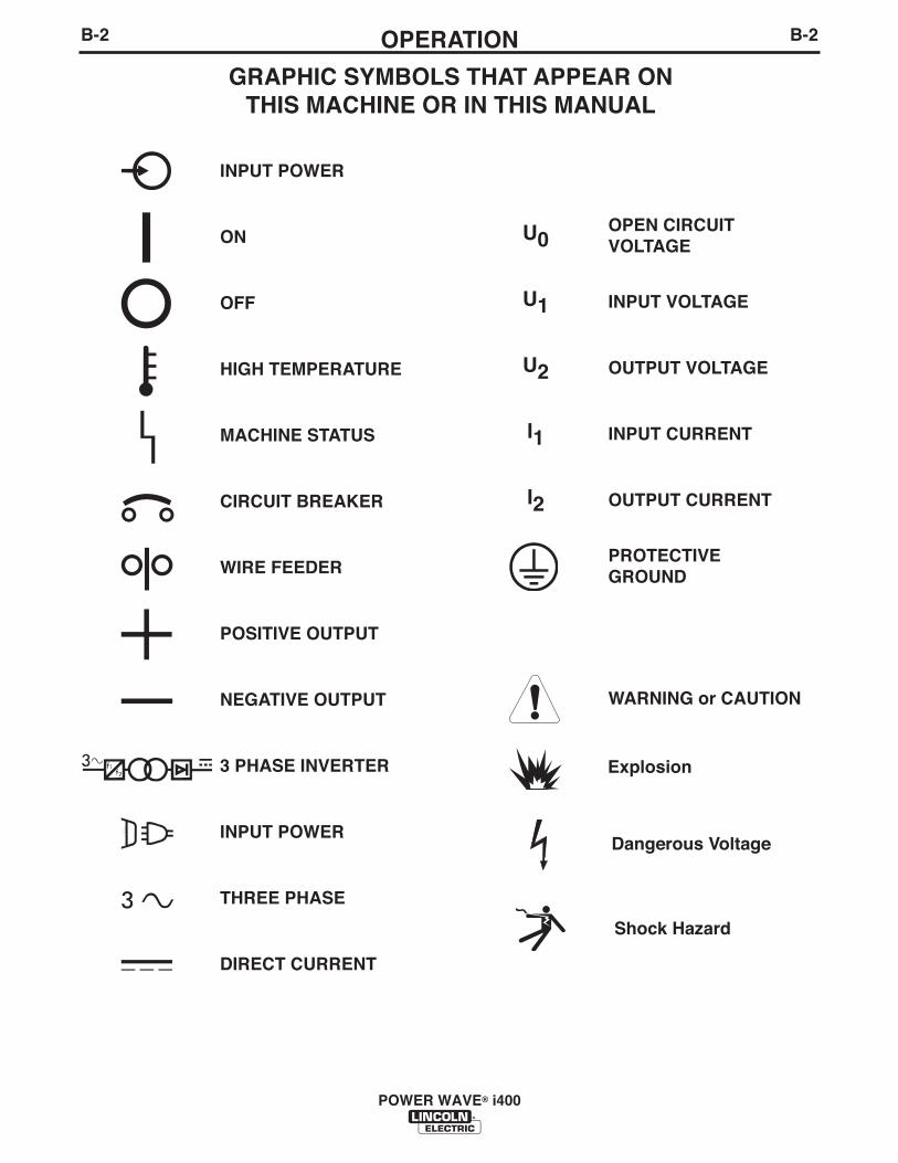
INPUT POWER
ON
OFF
HIGH TEMPERATURE
MACHINE STATUS
CIRCUIT BREAKER
WIRE FEEDER
POSITIVE OUTPUT
NEGATIVE OUTPUT
3 PHASE INVERTER
INPUT POWER
THREE PHASE
DIRECT CURRENT
OPEN CIRCUIT VOLTAGE
INPUT VOLTAGE
OUTPUT VOLTAGE
INPUT CURRENT
OUTPUT CURRENT
PROTECTIVEGROUND
WARNING or CAUTION
Explosion
Dangerous Voltage
Shock Hazard
GRAPHIC SYMBOLS THAT APPEAR ONTHIS MACHINE OR IN THIS MANUAL
U0
U1
U2
I1
I2
B-3OPERATIONB-3
PRODUCT DESCRIPTION
PRODUCT SUMMARY
General Physical Description
The POWER WAVE® i400 is intended as a replace-ment for the PW355i using an updated power andcontrol platform to enhance performance and reliabili-ty. The POWER WAVE® i400 includes an integratedwire drive module and 14-pin MS-Style connection tosupport the PF-10R and Auto Drive series. ArcLink®
communication is supported through the 5 pin MS-style interface. The new ArcLink®XT communicationprotocol is supported through an RJ-45 type Ethernetconnection, which also provides access for thePOWER WAVE® Utilities software tools. In addition,the DeviceNet communication protocol is supportedby a 5 pin sealed mini style receptacle. Access toremote voltage sensing is available through the 4 pinsense lead connector (work and electrode), at thefeeder via the 14 pin MS-style connector (electrodeonly), or at the 5 pin MS-style ArcLink® connector(electrode only).
Optional features include DeviceNet or Sync-Tandemcapability, and an internal filter kit to achieve CE com-pliance.
The POWER WAVE® i400 includes an innovative newcase design featuring a removable slide mountedpower section for ease of service. The case isdesigned to support the Fanuc R30iA / R30iB con-troller and op box (up to 300lbs), matching both thecontrollerʼs footprint and styling. Mounting is externallyaccessible for simplified integration. The flexibility ofthe POWER WAVE® i400 also allows it to be operatedas a stand alone unit.
Input power for the Fanuc R30iA / R30iB controller issupplied through the POWER WAVE® i400 on/offswitch. The ArcLink®XT connection is providedthrough Ethernet. Both power and communicationleads are routed to the controller via access holes inthe top of the power source. The K2677-2 IntegrationKit includes all necessary cables and hardware tocomplete this task.
General Functional Description
The POWER WAVE® i400 is a high performance,multi-process, digitally controlled inverter powersource, designed as a pedestal to support the FanucR30iA / R30iB controller. It may also be used withother controllers as a standalone power source. It iscapable of producing a welding output from 5-420amperes, and is rated for 350A, 100%.
The POWER WAVE® i400 utilizes the latest genera-tion high speed digital controls, and communicates viaArcLink®XT to the Fanuc controller. The inverterpower section utilizes state of the art power electron-ics and is re-connectable for 3 phase input voltagesfrom 208 to 575VAC. A 15A auxiliary receptacle isprovided for fume extraction and water cooler acces-sories.
The POWER WAVE® i400 is fully CE compatiblewhen equipped with a K2670-1 CE Filter kit*.
* Input voltage limited to 380-415/3/50/60 with kitinstalled.
RECOMMENDED PROCESSES ANDEQUIPMENT
RECOMMENDED PROCESSES
The POWER WAVE® i400 is a high speed, multi-process power source capable of regulating the cur-rent, voltage, or power of the welding arc. With an out-put range of 5 to 420 amperes, it supports a numberof standard processes including synergic GMAW,GMAW-P and FCAW on various materials especiallysteel, aluminum and stainless.
PROCESS LIMITATIONS
The software based weld set of the POWER WAVE®
i400 limit the process capability within the outputrange and the safe limits of the machine.
EQUIPMENT LIMITATIONS
The POWER WAVE® i400 is not directly compatiblewith analog machines or interfaces.
The input power pass-through connection (TerminalBlock - 4TB) of the POWER WAVE® i400 is intendedR30iA / R30iB controller. It is designed to support a3kW maximum robot controller load through cableprovided with the K2677-2 Integration Kit.
POWER WAVE® i400
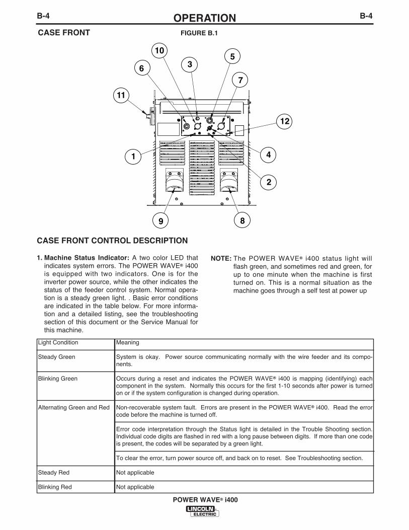
B-4OPERATIONB-4
CASE FRONT CONTROL DESCRIPTION
1. Machine Status Indicator: A two color LED thatindicates system errors. The POWER WAVE® i400is equipped with two indicators. One is for theinverter power source, while the other indicates thestatus of the feeder control system. Normal opera-tion is a steady green light. . Basic error conditionsare indicated in the table below. For more informa-tion and a detailed listing, see the troubleshootingsection of this document or the Service Manual forthis machine.
NOTE: The POWER WAVE® i400 status light willflash green, and sometimes red and green, forup to one minute when the machine is firstturned on. This is a normal situation as themachine goes through a self test at power up
POWER WAVE® i400
10
1
11
6
12
4
2
35
8
7
9
CASE FRONT FIGURE B.1
Light Condition
Steady Green
Blinking Green
Alternating Green and Red
Steady Red
Blinking Red
Meaning
System is okay. Power source communicating normally with the wire feeder and its compo-nents.
Occurs during a reset and indicates the POWER WAVE® i400 is mapping (identifying) eachcomponent in the system. Normally this occurs for the first 1-10 seconds after power is turnedon or if the system configuration is changed during operation.
Non-recoverable system fault. Errors are present in the POWER WAVE® i400. Read the errorcode before the machine is turned off.
Error code interpretation through the Status light is detailed in the Trouble Shooting section.Individual code digits are flashed in red with a long pause between digits. If more than one codeis present, the codes will be separated by a green light.
To clear the error, turn power source off, and back on to reset. See Troubleshooting section.
Not applicable
Not applicable
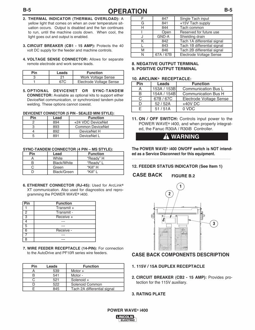
B-5OPERATIONB-5
2. THERMAL INDICATOR (THERMAL OVERLOAD): Ayellow light that comes on when an over temperature sit-uation occurs. Output is disabled and the fan continuesto run, until the machine cools down. When cool, thelight goes out and output is enabled.
3. CIRCUIT BREAKER (CB1 - 15 AMP): Protects the 40volt DC supply for the feeder and machine controls.
4. VOLTAGE SENSE CONNECTOR: Allows for separateremote electrode and work sense leads.
Pin Leads Function3 21 Work Voltage Sense1 67C Electrode Voltage Sense
5. OPTIONAL DEVICENET OR SYNC-TANDEMCONNECTOR: Available as optional kits to support eitherDeviceNet communication, or synchronized tandem pulsewelding. These options cannot coexist.
DEVICENET CONNECTOR (5 PIN - SEALED MINI STYLE):Pin Lead Function
2 894 +24 VDC DeviceNet3 893 Common DeviceNet4 892 DeviceNet H5 891 DeviceNet L
SYNC-TANDEM CONNECTOR (4 PIN – MS STYLE):Pin Lead FunctionA White “Ready” HB Black/White “Ready” LC Green “Kill” HD Black/Green “Kill” L
6. ETHERNET CONNECTOR (RJ-45): Used for ArcLink®
XT communication. Also used for diagnostics and repro-gramming the POWER WAVE® i400.
Pin Function1 Transmit +2 Transmit -3 Receive +4 ---5 ---6 Receive -7 ---8 ---
7. WIRE FEEDER RECEPTACLE (14-PIN): For connectionto the AutoDrive and PF10R series wire feeders.
Pin Leads FunctionA 539 Motor +B 541 Motor -C 521 Solenoid +D 522 Solenoid CommonE 845 Tach 2A differential signal
F 847 Single Tach inputG 841 +15V Tach supplyH 844 Tach commonI Open Reserved for future useJ GND-A Shielding drainK 842 Tach 1A differential signalL 843 Tach 1B differential signalM 846 Tach 2B differential signalN 67A / 67B Electrode Voltage Sense
8. NEGATIVE OUTPUT TERMINAL 9. POSITIVE OUTPUT TERMINAL
10. ARCLINK® RECEPTACLE:Pin Leads FunctionA 153A / 153B Communication Bus LB 154A / 154B Communication Bus HC 67B / 67C Electrode Voltage SenseD 52 / 52A +40V DCE 51 / 51A 0 VDC
11. ON / OFF SWITCH: Controls input power to thePOWER WAVE® i400, and when properly integrat-ed, the Fanuc R30iA / R30iB Controller.
The POWER WAVE® i400 ON/OFF switch is NOT intend-ed as a Service Disconnect for this equipment.-----------------------------------------------------------------------
12. FEEDER STATUS INDICATOR (See Item 1)
CASE BACK COMPONENTS DESCRIPTION
1. 115V / 15A DUPLEX RECEPTACLE
2. CIRCUIT BREAKER (CB2 - 15 AMP): Provides pro-tection for the 115V auxiliary.
3. RATING PLATE
POWER WAVE® i400
1
2
3
CASE BACK FIGURE B.2
WARNING
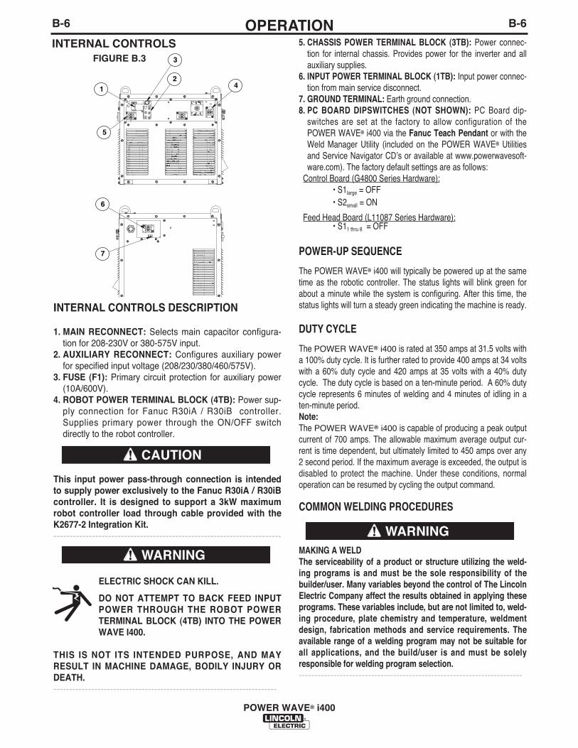
INTERNAL CONTROLS DESCRIPTION
1. MAIN RECONNECT: Selects main capacitor configura-tion for 208-230V or 380-575V input.
2. AUXILIARY RECONNECT: Configures auxiliary powerfor specified input voltage (208/230/380/460/575V).
3. FUSE (F1): Primary circuit protection for auxiliary power(10A/600V).
4. ROBOT POWER TERMINAL BLOCK (4TB): Power sup-ply connection for Fanuc R30iA / R30iB controller.Supplies primary power through the ON/OFF switchdirectly to the robot controller.
This input power pass-through connection is intendedto supply power exclusively to the Fanuc R30iA / R30iBcontroller. It is designed to support a 3kW maximumrobot controller load through cable provided with theK2677-2 Integration Kit.-----------------------------------------------------------------------
ELECTRIC SHOCK CAN KILL.
DO NOT ATTEMPT TO BACK FEED INPUTPOWER THROUGH THE ROBOT POWERTERMINAL BLOCK (4TB) INTO THE POWERWAVE I400.
THIS IS NOT ITS INTENDED PURPOSE, AND MAYRESULT IN MACHINE DAMAGE, BODILY INJURY ORDEATH.-----------------------------------------------------------------------
B-6OPERATIONB-6
POWER WAVE® i400
5. CHASSIS POWER TERMINAL BLOCK (3TB): Power connec-tion for internal chassis. Provides power for the inverter and allauxiliary supplies.
6. INPUT POWER TERMINAL BLOCK (1TB): Input power connec-tion from main service disconnect.
7. GROUND TERMINAL: Earth ground connection.8. PC BOARD DIPSWITCHES (NOT SHOWN): PC Board dip-
switches are set at the factory to allow configuration of thePOWER WAVE® i400 via the Fanuc Teach Pendant or with theWeld Manager Utility (included on the POWER WAVE® Utilitiesand Service Navigator CDʼs or available at www.powerwavesoft-ware.com). The factory default settings are as follows:
Control Board (G4800 Series Hardware):• S1large = OFF• S2small = ON
Feed Head Board (L11087 Series Hardware):• S11 thru 8 = OFF
POWER-UP SEQUENCE
The POWER WAVE® i400 will typically be powered up at the sametime as the robotic controller. The status lights will blink green forabout a minute while the system is configuring. After this time, thestatus lights will turn a steady green indicating the machine is ready.
DUTY CYCLE
The POWER WAVE® i400 is rated at 350 amps at 31.5 volts witha 100% duty cycle. It is further rated to provide 400 amps at 34 voltswith a 60% duty cycle and 420 amps at 35 volts with a 40% dutycycle. The duty cycle is based on a ten-minute period. A 60% dutycycle represents 6 minutes of welding and 4 minutes of idling in aten-minute period.Note:The POWER WAVE® i400 is capable of producing a peak outputcurrent of 700 amps. The allowable maximum average output cur-rent is time dependent, but ultimately limited to 450 amps over any2 second period. If the maximum average is exceeded, the output isdisabled to protect the machine. Under these conditions, normaloperation can be resumed by cycling the output command.
COMMON WELDING PROCEDURES
MAKING A WELDThe serviceability of a product or structure utilizing the weld-ing programs is and must be the sole responsibility of thebuilder/user. Many variables beyond the control of The LincolnElectric Company affect the results obtained in applying theseprograms. These variables include, but are not limited to, weld-ing procedure, plate chemistry and temperature, weldmentdesign, fabrication methods and service requirements. Theavailable range of a welding program may not be suitable forall applications, and the build/user is and must be solelyresponsible for welding program selection.-----------------------------------------------------------------------
INTERNAL CONTROLS
12
3
4
5
6
7
FIGURE B.3
CAUTION
WARNING
WARNING
B-7OPERATIONB-7
Choose the electrode material, electrode size, shield-ing gas, and process (GMAW, GMAW-P etc.) appro-priate for the material to be welded.
Select the weld mode that best matches the desiredwelding process. The standard weld set shipped withthe Power Wave i400 encompasses a wide range ofcommon processes that will meet most needs. If aspecial weld mode is desired, contact the local LincolnElectric sales representative.
To make a weld, the Power Wave i400 needs to knowthe desired welding parameters. The robot controllersends the parameters from the teach pendant (arcvoltage, wire feed speed, UltimArc™ value, etc.), tothe Power Wave i400 via the ArcLink® communicationprotocol over the control, Ethernet or optionalDeviceNet cables.
BASIC WELDING CONTROLS
Weld ModeSelecting a weld mode determines the output charac-teristics of the Power Wave i400 power source. Weldmodes are developed with a specific electrode materi-al, electrode size, and shielding gas. For a more com-plete description of the weld modes programmed intothe Power Wave at the factory, refer to the Weld SetReference Guide supplied with the machine or avail-able at www.powerwavesoftware.com.
Wire Feed Speed (WFS)In synergic welding modes (GMAW, GMAW-P), WFSis the dominant control parameter. The user adjustsWFS according to factors such as wire size, penetra-tion requirements, heat input, etc. The Power Wavethen uses the WFS setting to adjust the voltage andcurrent according to the information contained in theselected weld mode.
Note:The Power Wave i400 can be configured to useamperage as the dominant control parameterinstead of WFS for synergic welding modes. In thisconfiguration the user adjusts amperage accordingto factors such as wire size, penetration require-ments, heat input, etc. The Power Wave then usesthe amperage setting to adjust the WFS and volt-age according to the information contained in theselected weld mode.
This alternate configuration is regionally enabledbased on the robot controller software. Refer to theFanuc documentation for manual configurationinformation.
In non-synergic modes, the WFS control behaves likea conventional power source where WFS and voltageare independent adjustments. Therefore, to maintainproper arc characteristics, the operator must adjustthe voltage to compensate for any changes made tothe WFS.
Volts In constant voltage modes (GMAW), this controladjusts the welding voltage.
TrimIn pulse synergic welding modes (GMAW-P), the Trimsetting adjusts the arc length. Trim is adjustable from0.50 to 1.50. 1.00 is the nominal setting and is a goodstarting point for most conditions.
Note:The Power Wave i400 can also be configured todisplay Trim as a voltage value. This allows theoperator to pre-set an approximate welding voltagerather than a unitless Trim value. The pre-set volt-age is limited based on the process, and providesthe same range of operation as the correspondingTrim value.
This alternate configuration is regionally enabledbased on the robot controller software. Refer to theFanuc documentation for manual configurationinformation.
UltimArcTM
UltimArcTM allows the operator to vary the arc charac-teristics from “soft” to “crisp”. UltimArcTM is adjustablefrom –10.0 to +10.0 with a nominal setting of 0.0.
CONSTANT VOLTAGE WELDING
Synergic CVIn synergic welding modes, WFS is the dominant con-trol parameter. For each wire feed speed, a corre-sponding voltage is programmed into the machine atthe factory. The user adjusts WFS according to fac-tors such as wire size, material thickness, penetrationrequirements, etc. The Power Wave i400 then usesthe WFS setting to select the appropriate nominal volt-age. The Power Wave i400 can also be configured touse amperage as the dominant control parameter. Inthis configuration the Power Wave i400 uses theamperage setting to select the appropriate WFS andnominal voltage. In either case, the user can adjustthe voltage higher or lower to compensate for materialcondition or individual preference.
POWER WAVE® i400
Pulse welding modes are synergic; using wire feedspeed as the main control parameter. As the wirefeed speed is adjusted, the power source adjusts thewaveform parameters to maintain good welding char-acteristics. The Power Wave® i400 can also be config-ured to use amperage as the dominant control para-meter. In this configuration, as the amperage isadjusted, the power source selects the appropriatewire feed speed, and adjusts the waveform parame-ters to maintain good welding characteristics. In eithercase, trim is used as a secondary control to changethe arc length for material conditions or individual pref-erence.
UltimArcTM adjusts the focus or shape of the arc.UltimArcTM is adjustable from -10.0 to +10.0 with anominal setting of 0.0. Increasing the UltimArcTM
increases the pulse frequency and background cur-rent while decreasing the peak current. This results ina tight, stiff arc used for high speed sheet metal weld-ing. Decreasing the UltimArcTM decreases the pulsefrequency and background current while increasingthe peak current. This results in a soft arc good for outof position welding.
The Power Wave® utilizes adaptive control to compen-sate for changes in the electrical stick-out (distancefrom the contact tip to the work piece) while welding.The Power Wave® waveforms are optimized for a 5/8”to 3/4” stick out depending on the wire type and wirefeed speed. The adaptive behavior supports a rangeof stick outs from approximately 1/2” to 1-1/4”. At lowor high wire feed speeds, the adaptive range may beless due to physical limitations of the welding process.
B-8OPERATION
POWER WAVE® i400
B-8
Non Synergic CVIn non-synergic modes, the machine behaves like aconventional power source. The WFS and voltageare independent adjustments. Therefore, to maintainthe arc characteristics, the operator must adjust thevoltage to compensate for any changes made to theWFS.
UltimArcTM
UltimArcTM adjusts the apparent inductance of thewave shape. The UltimArcTM adjustment is similar to a“pinch” function in that it is inversely proportional toinductance. UltimArcTM is adjustable from –10.0 to+10.0 with a nominal sett ing of 0. IncreasingUltimArcTM results in a crisper, hotter arc. Decreasingthe UltimArcTM provides a softer, colder arc.
Pulse Welding
When pulse welding, the power source primarily regu-lates the arc current, not the arc voltage. During apulsing cycle, arc current is regulated from a lowbackground level to a high peak level and then backdown to the low background level. The average arcvoltage increases and decreases as the average arccurrent is increased or decreased. The peak current,back ground current, rise time, fall time and pulse fre-quency all affect the average voltage. Since the aver-age voltage for a given wire feed speed can only bedetermined when all the pulsing waveform parametersare known, a unitless value called “trim” is used foradjusting the arc length.
Trim adjusts the arc length and ranges from 0.50 to1.50 with a nominal value of 1.00. Increasing the trimvalue increases the arc length. Decreasing the trimvalue decreases the arc length. Alternately, trim canbe displayed as a quasi-voltage value. This allows theoperator to pre-set an approximate welding voltagerather than a unitless trim value. The pre-set voltageis limited based on the process, and provides thesame range of operation as the corresponding trimvalue.
C-1ACCESSORIESC-1
OPTIONAL EQUIPMENT
FACTORY INSTALLEDNone Available.
FIELD INSTALLED K940-Work Voltage Sense Lead Kit
K2670-[ ] CE Filter KitK2677-2 Integration Kit
COMPATIBLE LINCOLN EQUIPMENT
K2685-2 Auto Drive 4R90 Wire feeder (14-pin controlcable).
K1780-2 Power Feed 10 Robotic Wire Drive
For additional Information see Optional Equipment inthe Installation Section.
POWER WAVE® i400
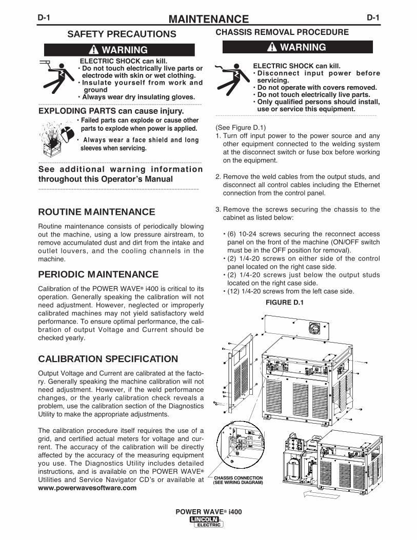
CHASSIS REMOVAL PROCEDURE
ELECTRIC SHOCK can kill.• Disconnect input power before
servicing.• Do not operate with covers removed.• Do not touch electrically live parts.• Only qualified persons should install,
use or service this equipment.-----------------------------------------------------------------------
(See Figure D.1)1. Turn off input power to the power source and any
other equipment connected to the welding systemat the disconnect switch or fuse box before workingon the equipment.
2. Remove the weld cables from the output studs, anddisconnect all control cables including the Ethernetconnection from the control panel.
3. Remove the screws securing the chassis to thecabinet as listed below:
• (6) 10-24 screws securing the reconnect accesspanel on the front of the machine (ON/OFF switchmust be in the OFF position for removal).
• (2) 1/4-20 screws on either side of the controlpanel located on the right case side.
• (2) 1/4-20 screws just below the output studslocated on the right case side.
• (12) 1/4-20 screws from the left case side.
D-1MAINTENANCED-1
POWER WAVE® i400
SAFETY PRECAUTIONS
ROUTINE MAINTENANCERoutine maintenance consists of periodically blowingout the machine, using a low pressure airstream, toremove accumulated dust and dirt from the intake andoutlet louvers, and the cooling channels in themachine.
PERIODIC MAINTENANCECalibration of the POWER WAVE® i400 is critical to itsoperation. Generally speaking the calibration will notneed adjustment. However, neglected or improperlycalibrated machines may not yield satisfactory weldperformance. To ensure optimal performance, the cali-bration of output Voltage and Current should bechecked yearly.
CALIBRATION SPECIFICATIONOutput Voltage and Current are calibrated at the facto-ry. Generally speaking the machine calibration will notneed adjustment. However, if the weld performancechanges, or the yearly calibration check reveals aproblem, use the calibration section of the DiagnosticsUtility to make the appropriate adjustments.
The calibration procedure itself requires the use of agrid, and certified actual meters for voltage and cur-rent. The accuracy of the calibration will be directlyaffected by the accuracy of the measuring equipmentyou use. The Diagnostics Utility includes detailedinstructions, and is available on the POWER WAVE®
Utilities and Service Navigator CDʼs or available atwww.powerwavesoftware.com
ELECTRIC SHOCK can kill.• Do not touch electrically live parts or
electrode with skin or wet clothing.• Insulate yourself from work and
ground• Always wear dry insulating gloves.
------------------------------------------------------------------------EXPLODING PARTS can cause injury.
• Failed parts can explode or cause otherparts to explode when power is applied.
• Always wear a face shield and longsleeves when servicing.
------------------------------------------------------------------------See additional warning informationthroughout this Operatorʼs Manual -----------------------------------------------------------
WARNING WARNING
CHASSIS CONNECTION(SEE WIRING DIAGRAM)
FIGURE D.1
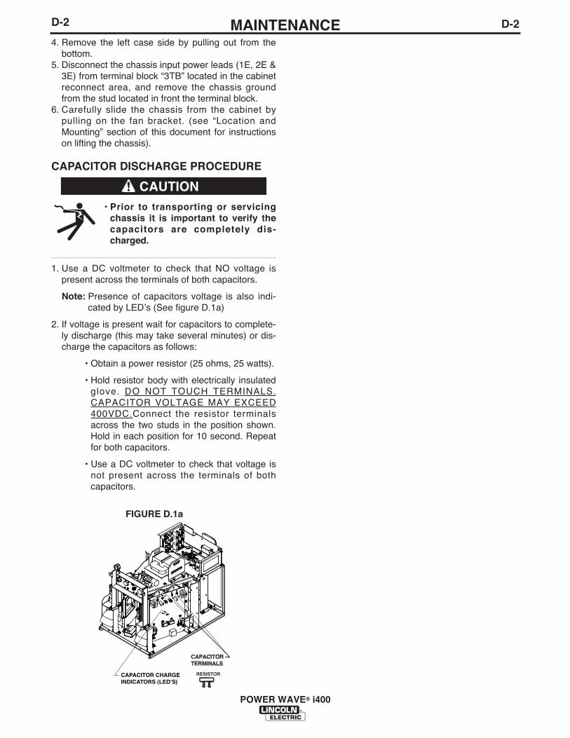
D-2MAINTENANCED-2
POWER WAVE® i400
FIGURE D.1a
4. Remove the left case side by pulling out from thebottom.
5. Disconnect the chassis input power leads (1E, 2E &3E) from terminal block “3TB” located in the cabinetreconnect area, and remove the chassis groundfrom the stud located in front the terminal block.
6. Carefully slide the chassis from the cabinet bypulling on the fan bracket. (see “Location andMounting” section of this document for instructionson lifting the chassis).
CAPACITOR DISCHARGE PROCEDURE
• Prior to transporting or servicingchassis it is important to verify thecapacitors are completely dis-charged.
-----------------------------------------------------------------------1. Use a DC voltmeter to check that NO voltage is
present across the terminals of both capacitors.
Note: Presence of capacitors voltage is also indi-cated by LEDʼs (See figure D.1a)
2. If voltage is present wait for capacitors to complete-ly discharge (this may take several minutes) or dis-charge the capacitors as follows:
• Obtain a power resistor (25 ohms, 25 watts).
• Hold resistor body with electrically insulatedglove. DO NOT TOUCH TERMINALS.CAPACITOR VOLTAGE MAY EXCEED400VDC.Connect the resistor terminalsacross the two studs in the position shown.Hold in each position for 10 second. Repeatfor both capacitors.
• Use a DC voltmeter to check that voltage isnot present across the terminals of bothcapacitors.
CAPACITORTERMINALS
RESISTORCAPACITOR CHARGEINDICATORS (LED’S)
CAUTION

E-1TROUBLESHOOTINGE-1
POWER WAVE® i400
If for any reason you do not understand the test procedures or are unable to perform the tests/repairs safely, contact yourLocal Lincoln Authorized Field Service Facility for technical troubleshooting assistance before you proceed.
CAUTION
This Troubleshooting Guide is provided to help youlocate and repair possible machine malfunctions.Simply follow the three-step procedure listed below.
Step 1. LOCATE PROBLEM (SYMPTOM).Look under the column labeled “PROBLEM (SYMP-TOMS)”. This column describes possible symptomsthat the machine may exhibit. Find the listing thatbest describes the symptom that the machine isexhibiting.
Step 2. POSSIBLE CAUSE.The second column labeled “POSSIBLE CAUSE” liststhe obvious external possibilities that may contributeto the machine symptom.
Step 3. RECOMMENDED COURSE OF ACTIONThis column provides a course of action for thePossible Cause, generally it states to contact yourlocal Lincoln Authorized Field Service Facility.
If you do not understand or are unable to perform theRecommended Course of Action safely, contact yourlocal Lincoln Authorized Field Service Facility.
HOW TO USE TROUBLESHOOTING GUIDE
Service and Repair should only be performed by Lincoln Electric Factory Trained Personnel.Unauthorized repairs performed on this equipment may result in danger to the technician andmachine operator and will invalidate your factory warranty. For your safety and to avoid ElectricalShock, please observe all safety notes and precautions detailed throughout this manual.
__________________________________________________________________________
WARNING
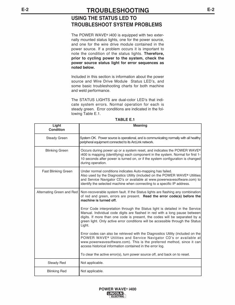
E-2TROUBLESHOOTINGE-2
POWER WAVE® i400
USING THE STATUS LED TOTROUBLESHOOT SYSTEM PROBLEMS
The POWER WAVE® i400 is equipped with two exter-nally mounted status lights, one for the power source,and one for the wire drive module contained in thepower source. If a problem occurs it is important tonote the condition of the status lights. Therefore,prior to cycling power to the system, check thepower source status light for error sequences asnoted below.
Included in this section is information about the powersource and Wire Drive Module Status LEDʼs, andsome basic troubleshooting charts for both machineand weld performance.
The STATUS LIGHTS are dual-color LEDʼs that indi-cate system errors. Normal operation for each issteady green. Error conditions are indicated in the fol-lowing Table E.1.
LightCondition
Steady Green
Blinking Green
Fast Blinking Green
Alternating Green and Red
Steady Red
Blinking Red
Meaning
System OK. Power source is operational, and is communicating normally with all healthyperipheral equipment connected to its ArcLink network.
Occurs during power up or a system reset, and indicates the POWER WAVE®
i400 is mapping (identifying) each component in the system. Normal for first 1-10 seconds after power is turned on, or if the system configuration is changedduring operation.
Under normal conditions indicates Auto-mapping has failed. Also used by the Diagnostics Utility (included on the POWER WAVE® Utilitiesand Service Navigator CDʼs or available at www.powerwavesoftware.com) toidentify the selected machine when connecting to a specific IP address.
Non-recoverable system fault. If the Status lights are flashing any combinationof red and green, errors are present. Read the error code(s) before themachine is turned off.
Error Code interpretation through the Status light is detailed in the ServiceManual. Individual code digits are flashed in red with a long pause betweendigits. If more than one code is present, the codes will be separated by agreen light. Only active error conditions will be accessible through the StatusLight.
Error codes can also be retrieved with the Diagnostics Utility (included on thePOWER WAVE® Utilities and Service Navigator CDʼs or available atwww.powerwavesoftware.com). This is the preferred method, since it canaccess historical information contained in the error log.
To clear the active error(s), turn power source off, and back on to reset.
Not applicable.
Not applicable.
TABLE E.1
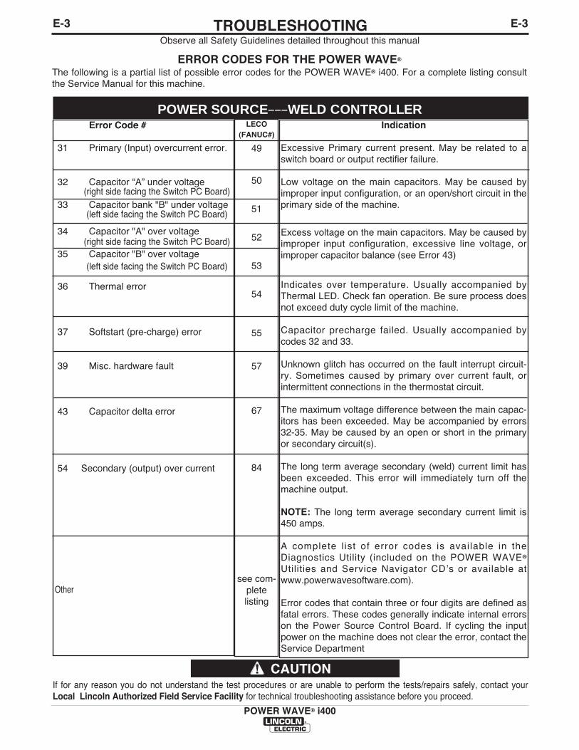
LECO(FANUC#)
49
50
51
52
53
54
55
57
67
84
see com-plete listing
POWER SOURCE–––WELD CONTROLLER
E-3TROUBLESHOOTINGE-3
POWER WAVE® i400
Observe all Safety Guidelines detailed throughout this manual
If for any reason you do not understand the test procedures or are unable to perform the tests/repairs safely, contact yourLocal Lincoln Authorized Field Service Facility for technical troubleshooting assistance before you proceed.
CAUTION
ERROR CODES FOR THE POWER WAVE®
The following is a partial list of possible error codes for the POWER WAVE® i400. For a complete listing consultthe Service Manual for this machine.
Error Code #
31 Primary (Input) overcurrent error.
32 Capacitor “A” under voltage (right side facing the Switch PC Board)
33 Capacitor bank "B" under voltage(left side facing the Switch PC Board)
34 Capacitor "A" over voltage (right side facing the Switch PC Board)
35 Capacitor "B" over voltage(left side facing the Switch PC Board)
36 Thermal error
37 Softstart (pre-charge) error
39 Misc. hardware fault
43 Capacitor delta error
54 Secondary (output) over current
Other
Indication
Excessive Primary current present. May be related to aswitch board or output rectifier failure.
Low voltage on the main capacitors. May be caused byimproper input configuration, or an open/short circuit in theprimary side of the machine.
Excess voltage on the main capacitors. May be caused byimproper input configuration, excessive line voltage, orimproper capacitor balance (see Error 43)
Indicates over temperature. Usually accompanied byThermal LED. Check fan operation. Be sure process doesnot exceed duty cycle limit of the machine.
Capacitor precharge failed. Usually accompanied bycodes 32 and 33.
Unknown glitch has occurred on the fault interrupt circuit-ry. Sometimes caused by primary over current fault, orintermittent connections in the thermostat circuit.
The maximum voltage difference between the main capac-itors has been exceeded. May be accompanied by errors32-35. May be caused by an open or short in the primaryor secondary circuit(s).
The long term average secondary (weld) current limit hasbeen exceeded. This error will immediately turn off themachine output.
NOTE: The long term average secondary current limit is450 amps.
A complete l ist of error codes is available in theDiagnostics Utility (included on the POWER WAVE®
Utilities and Service Navigator CDʼs or available atwww.powerwavesoftware.com).
Error codes that contain three or four digits are defined asfatal errors. These codes generally indicate internal errorson the Power Source Control Board. If cycling the inputpower on the machine does not clear the error, contact theService Department
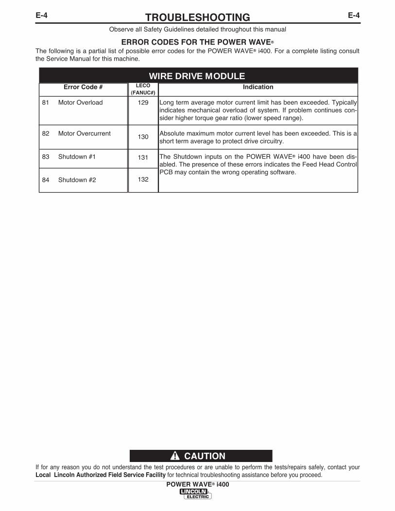
LECO(FANUC#)
129
130
131
132
E-4TROUBLESHOOTINGE-4
POWER WAVE® i400
If for any reason you do not understand the test procedures or are unable to perform the tests/repairs safely, contact yourLocal Lincoln Authorized Field Service Facility for technical troubleshooting assistance before you proceed.
CAUTION
WIRE DRIVE MODULE
Observe all Safety Guidelines detailed throughout this manual
ERROR CODES FOR THE POWER WAVE®
The following is a partial list of possible error codes for the POWER WAVE® i400. For a complete listing consultthe Service Manual for this machine.
Error Code #
81 Motor Overload
82 Motor Overcurrent
83 Shutdown #1
84 Shutdown #2
Indication
Long term average motor current limit has been exceeded. Typicallyindicates mechanical overload of system. If problem continues con-sider higher torque gear ratio (lower speed range).
Absolute maximum motor current level has been exceeded. This is ashort term average to protect drive circuitry.
The Shutdown inputs on the POWER WAVE® i400 have been dis-abled. The presence of these errors indicates the Feed Head ControlPCB may contain the wrong operating software.
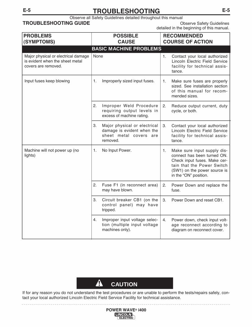
E-5TROUBLESHOOTINGE-5
POWER WAVE® i400
Observe all Safety Guidelines detailed throughout this manualTROUBLESHOOTING GUIDE Observe Safety Guidelines
detailed in the beginning of this manual.
CAUTIONIf for any reason you do not understand the test procedures or are unable to perform the tests/repairs safely, con-tact your local authorized Lincoln Electric Field Service Facility for technical assistance.
PROBLEMS(SYMPTOMS)
POSSIBLECAUSE
RECOMMENDEDCOURSE OF ACTION
BASIC MACHINE PROBLEMSMajor physical or electrical damageis evident when the sheet metalcovers are removed.
Input fuses keep blowing
Machine will not power up (nolights)
None
1. Improperly sized input fuses.
2. Improper Weld Procedurerequiring output levels inexcess of machine rating.
3. Major physical or electricaldamage is evident when thesheet metal covers areremoved.
1. No Input Power.
2. Fuse F1 (in reconnect area)may have blown.
3. Circuit breaker CB1 (on thecontrol panel) may havetripped.
4. Improper input voltage selec-tion (multiple input voltagemachines only).
1. Contact your local authorizedLincoln Electric Field Servicefacility for technical assis-tance.
1. Make sure fuses are properlysized. See installation sectionof this manual for recom-mended sizes.
2. Reduce output current, dutycycle, or both.
3. Contact your local authorizedLincoln Electric Field Servicefacility for technical assis-tance.
1. Make sure input supply dis-connect has been turned ON.Check input fuses. Make cer-tain that the Power Switch(SW1) on the power source isin the “ON” position.
2. Power Down and replace thefuse.
3. Power Down and reset CB1.
4. Power down, check input volt-age reconnect according todiagram on reconnect cover.
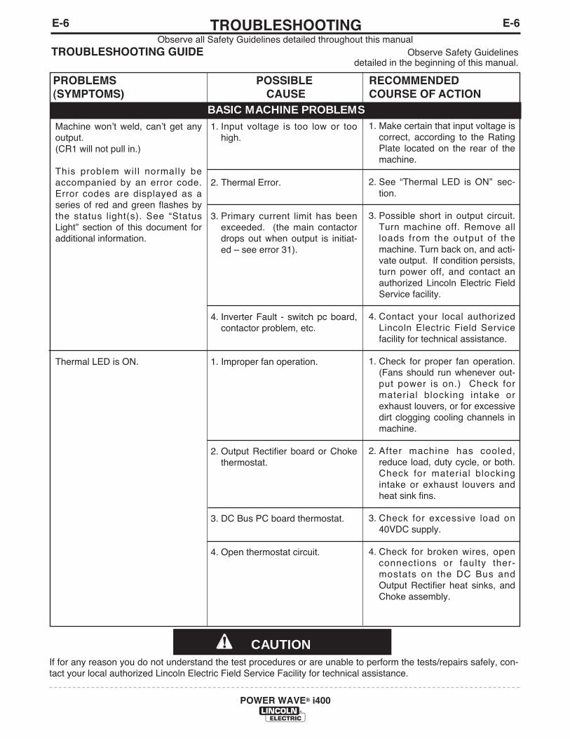
E-6TROUBLESHOOTINGE-6
POWER WAVE® i400
Observe all Safety Guidelines detailed throughout this manualTROUBLESHOOTING GUIDE Observe Safety Guidelines
detailed in the beginning of this manual.
CAUTIONIf for any reason you do not understand the test procedures or are unable to perform the tests/repairs safely, con-tact your local authorized Lincoln Electric Field Service Facility for technical assistance.
PROBLEMS(SYMPTOMS)
POSSIBLECAUSE
RECOMMENDEDCOURSE OF ACTION
BASIC MACHINE PROBLEMSMachine wonʼt weld, canʼt get anyoutput. (CR1 will not pull in.)
This problem wil l normally beaccompanied by an error code.Error codes are displayed as aseries of red and green flashes bythe status light(s). See “StatusLight” section of this document foradditional information.
Thermal LED is ON.
1. Input voltage is too low or toohigh.
2. Thermal Error.
3. Primary current limit has beenexceeded. (the main contactordrops out when output is initiat-ed – see error 31).
4. Inverter Fault - switch pc board,contactor problem, etc.
1. Improper fan operation.
2. Output Rectifier board or Chokethermostat.
3. DC Bus PC board thermostat.
4. Open thermostat circuit.
1. Make certain that input voltage iscorrect, according to the RatingPlate located on the rear of themachine.
2. See “Thermal LED is ON” sec-tion.
3. Possible short in output circuit.Turn machine off. Remove allloads from the output of themachine. Turn back on, and acti-vate output. If condition persists,turn power off, and contact anauthorized Lincoln Electric FieldService facility.
4. Contact your local authorizedLincoln Electric Field Servicefacility for technical assistance.
1. Check for proper fan operation.(Fans should run whenever out-put power is on.) Check formaterial blocking intake orexhaust louvers, or for excessivedirt clogging cooling channels inmachine.
2. After machine has cooled,reduce load, duty cycle, or both.Check for material blockingintake or exhaust louvers andheat sink fins.
3. Check for excessive load on40VDC supply.
4. Check for broken wires, openconnections or faulty ther-mostats on the DC Bus andOutput Rectifier heat sinks, andChoke assembly.
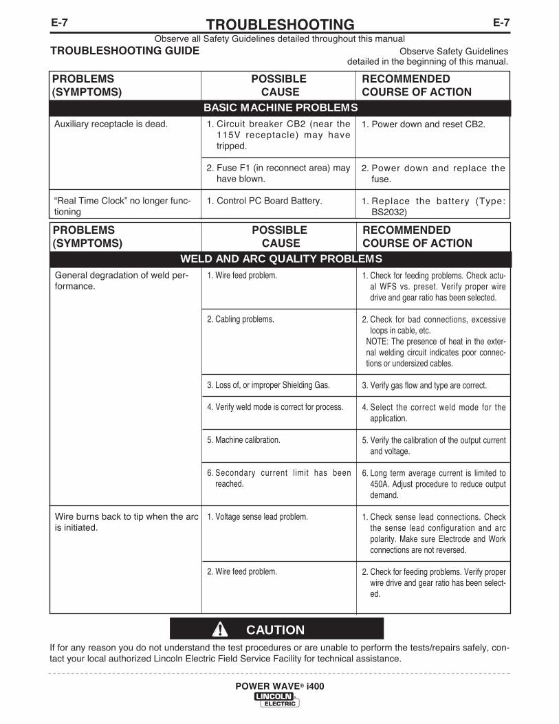
E-7TROUBLESHOOTINGE-7
POWER WAVE® i400
Observe all Safety Guidelines detailed throughout this manualTROUBLESHOOTING GUIDE Observe Safety Guidelines
detailed in the beginning of this manual.
CAUTIONIf for any reason you do not understand the test procedures or are unable to perform the tests/repairs safely, con-tact your local authorized Lincoln Electric Field Service Facility for technical assistance.
PROBLEMS(SYMPTOMS)
POSSIBLECAUSE
RECOMMENDEDCOURSE OF ACTION
BASIC MACHINE PROBLEMSAuxiliary receptacle is dead.
“Real Time Clock” no longer func-tioning
1. Circuit breaker CB2 (near the115V receptacle) may havetripped.
2. Fuse F1 (in reconnect area) mayhave blown.
1. Control PC Board Battery.
1. Power down and reset CB2.
2. Power down and replace thefuse.
1. Replace the battery (Type:BS2032)
PROBLEMS(SYMPTOMS)
POSSIBLECAUSE
RECOMMENDEDCOURSE OF ACTION
WELD AND ARC QUALITY PROBLEMSGeneral degradation of weld per-formance.
Wire burns back to tip when the arcis initiated.
1. Wire feed problem.
2. Cabling problems.
3. Loss of, or improper Shielding Gas.
4. Verify weld mode is correct for process.
5. Machine calibration.
6. Secondary current l imit has beenreached.
1. Voltage sense lead problem.
2. Wire feed problem.
1. Check for feeding problems. Check actu-al WFS vs. preset. Verify proper wiredrive and gear ratio has been selected.
2. Check for bad connections, excessiveloops in cable, etc.
NOTE: The presence of heat in the exter-nal welding circuit indicates poor connec-tions or undersized cables.
3. Verify gas flow and type are correct.
4. Select the correct weld mode for theapplication.
5. Verify the calibration of the output currentand voltage.
6. Long term average current is limited to450A. Adjust procedure to reduce outputdemand.
1. Check sense lead connections. Checkthe sense lead configuration and arcpolarity. Make sure Electrode and Workconnections are not reversed.
2. Check for feeding problems. Verify properwire drive and gear ratio has been select-ed.
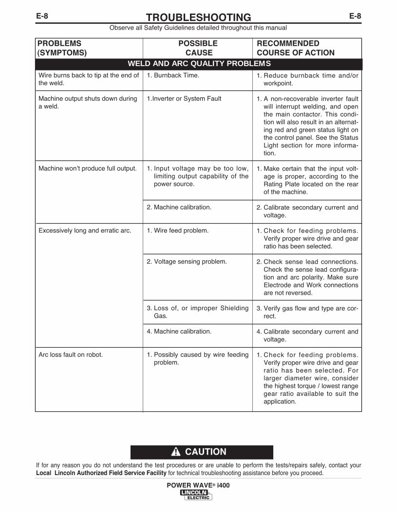
E-8TROUBLESHOOTINGE-8
POWER WAVE® i400
Observe all Safety Guidelines detailed throughout this manual
If for any reason you do not understand the test procedures or are unable to perform the tests/repairs safely, contact yourLocal Lincoln Authorized Field Service Facility for technical troubleshooting assistance before you proceed.
CAUTION
PROBLEMS(SYMPTOMS)
POSSIBLECAUSE
RECOMMENDEDCOURSE OF ACTION
WELD AND ARC QUALITY PROBLEMSWire burns back to tip at the end ofthe weld.
Machine output shuts down duringa weld.
Machine wonʼt produce full output.
Excessively long and erratic arc.
Arc loss fault on robot.
1. Burnback Time.
1.Inverter or System Fault
1. Input voltage may be too low,limiting output capability of thepower source.
2. Machine calibration.
1. Wire feed problem.
2. Voltage sensing problem.
3. Loss of, or improper ShieldingGas.
4. Machine calibration.
1. Possibly caused by wire feedingproblem.
1. Reduce burnback time and/orworkpoint.
1. A non-recoverable inverter faultwill interrupt welding, and openthe main contactor. This condi-tion will also result in an alternat-ing red and green status light onthe control panel. See the StatusLight section for more informa-tion.
1. Make certain that the input volt-age is proper, according to theRating Plate located on the rearof the machine.
2. Calibrate secondary current andvoltage.
1. Check for feeding problems.Verify proper wire drive and gearratio has been selected.
2. Check sense lead connections.Check the sense lead configura-tion and arc polarity. Make sureElectrode and Work connectionsare not reversed.
3. Verify gas flow and type are cor-rect.
4. Calibrate secondary current andvoltage.
1. Check for feeding problems.Verify proper wire drive and gearratio has been selected. Forlarger diameter wire, considerthe highest torque / lowest rangegear ratio available to suit theapplication.
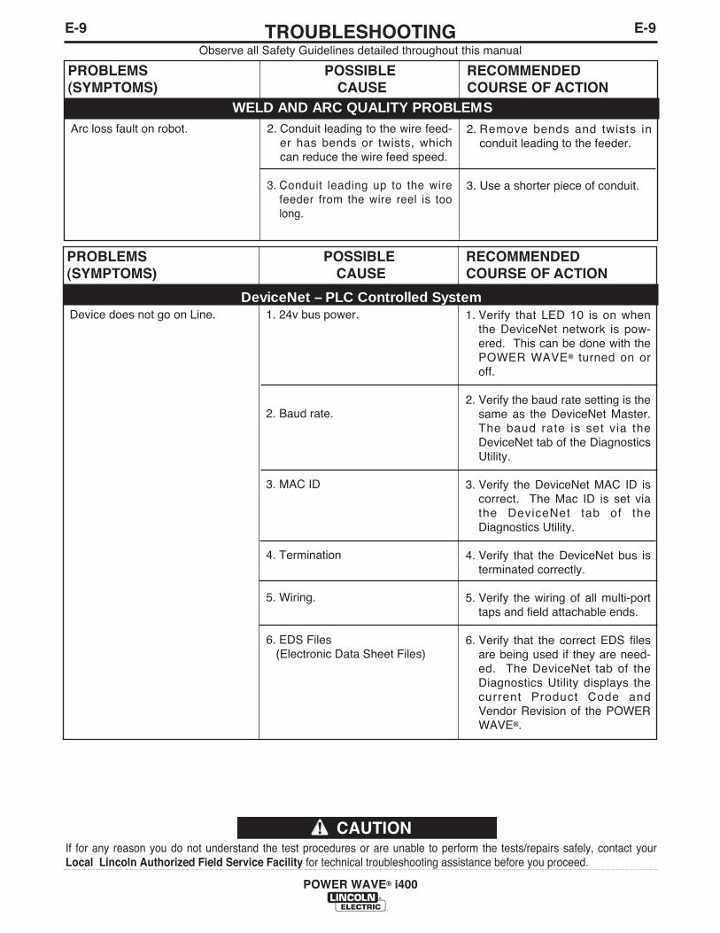
E-9TROUBLESHOOTINGE-9
POWER WAVE® i400
Observe all Safety Guidelines detailed throughout this manual
If for any reason you do not understand the test procedures or are unable to perform the tests/repairs safely, contact yourLocal Lincoln Authorized Field Service Facility for technical troubleshooting assistance before you proceed.
CAUTION
PROBLEMS(SYMPTOMS)
POSSIBLECAUSE
RECOMMENDEDCOURSE OF ACTION
WELD AND ARC QUALITY PROBLEMSArc loss fault on robot. 2. Conduit leading to the wire feed-
er has bends or twists, whichcan reduce the wire feed speed.
3. Conduit leading up to the wirefeeder from the wire reel is toolong.
2. Remove bends and twists inconduit leading to the feeder.
3. Use a shorter piece of conduit.
PROBLEMS(SYMPTOMS)
POSSIBLECAUSE
RECOMMENDEDCOURSE OF ACTION
DeviceNet – PLC Controlled SystemDevice does not go on Line. 1. 24v bus power.
2. Baud rate.
3. MAC ID
4. Termination
5. Wiring.
6. EDS Files(Electronic Data Sheet Files)
1. Verify that LED 10 is on whenthe DeviceNet network is pow-ered. This can be done with thePOWER WAVE® turned on oroff.
2. Verify the baud rate setting is thesame as the DeviceNet Master.The baud rate is set via theDeviceNet tab of the DiagnosticsUtility.
3. Verify the DeviceNet MAC ID iscorrect. The Mac ID is set viathe DeviceNet tab of theDiagnostics Utility.
4. Verify that the DeviceNet bus isterminated correctly.
5. Verify the wiring of all multi-porttaps and field attachable ends.
6. Verify that the correct EDS filesare being used if they are need-ed. The DeviceNet tab of theDiagnostics Utility displays thecurrent Product Code andVendor Revision of the POWERWAVE®.
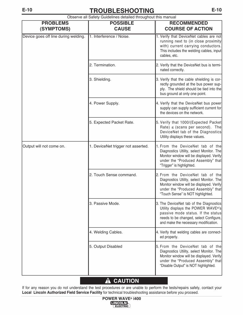
E-10TROUBLESHOOTINGE-10
POWER WAVE® i400
Observe all Safety Guidelines detailed throughout this manual
If for any reason you do not understand the test procedures or are unable to perform the tests/repairs safely, contact yourLocal Lincoln Authorized Field Service Facility for technical troubleshooting assistance before you proceed.
CAUTION
PROBLEMS(SYMPTOMS)
POSSIBLECAUSE
RECOMMENDEDCOURSE OF ACTION
Device goes off line during welding.
Output will not come on.
1. Interference / Noise.
2. Termination.
3. Shielding.
4. Power Supply.
5. Expected Packet Rate.
1. DeviceNet trigger not asserted.
2. Touch Sense command.
3. Passive Mode.
4. Welding Cables.
5. Output Disabled
1. Verify that DeviceNet cables are notrunning next to (in close proximitywith) current carrying conductors.This includes the welding cables, inputcables, etc.
2. Verify that the DeviceNet bus is termi-nated correctly.
3. Verify that the cable shielding is cor-rectly grounded at the bus power sup-ply. The shield should be tied into thebus ground at only one point.
4. Verify that the DeviceNet bus powersupply can supply sufficient current forthe devices on the network.
5. Verify that 1000/(Expected PacketRate) ≤ (scans per second). TheDeviceNet tab of the DiagnosticsUtility displays these values.
1. From the DeviceNet tab of theDiagnostics Utility, select Monitor. TheMonitor window will be displayed. Verifyunder the “Produced Assembly” that“Trigger” is highlighted.
2. From the DeviceNet tab of theDiagnostics Utility, select Monitor. TheMonitor window will be displayed. Verifyunder the “Produced Assembly” that“Touch Sense” is NOT highlighted.
3. The DeviceNet tab of the DiagnosticsUtility displays the POWER WAVE®ʼspassive mode status. If the statusneeds to be changed, select Configure,and make the necessary modification.
4. Verify that welding cables are connect-ed properly.
5. From the DeviceNet tab of theDiagnostics Utility, select Monitor. TheMonitor window will be displayed. Verifyunder the “Produced Assembly” that“Disable Output” is NOT highlighted.
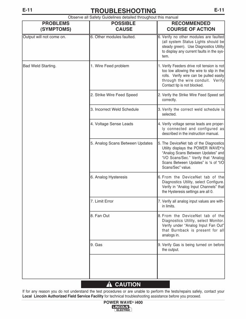
E-11TROUBLESHOOTINGE-11
POWER WAVE® i400
Observe all Safety Guidelines detailed throughout this manual
If for any reason you do not understand the test procedures or are unable to perform the tests/repairs safely, contact yourLocal Lincoln Authorized Field Service Facility for technical troubleshooting assistance before you proceed.
CAUTION
PROBLEMS(SYMPTOMS)
POSSIBLECAUSE
RECOMMENDEDCOURSE OF ACTION
Output will not come on.
Bad Weld Starting.
6. Other modules faulted.
1. Wire Feed problem
2. Strike Wire Feed Speed
3. Incorrect Weld Schedule
4. Voltage Sense Leads
5. Analog Scans Between Updates
6. Analog Hysteresis
7. Limit Error
8. Fan Out
9. Gas
6. Verify no other modules are faulted(all system Status Lights should besteady green). Use Diagnostics Utilityto display any current faults in the sys-tem.
1. Verify Feeders drive roll tension is nottoo low allowing the wire to slip in therolls. Verify wire can be pulled easilythrough the wire conduit. VerifyContact tip is not blocked.
2. Verify the Strike Wire Feed Speed setcorrectly.
3. Verify the correct weld schedule isselected.
4. Verify voltage sense leads are proper-ly connected and configured asdescribed in the instruction manual.
5. The DeviceNet tab of the DiagnosticsUtility displays the POWER WAVE®ʼs“Analog Scans Between Updates” and“I/O Scans/Sec.” Verify that “AnalogScans Between Updates” is ¼ of “I/OScans/Sec” value.
6. From the DeviceNet tab of theDiagnostics Utility, select Configure.Verify in “Analog Input Channels” thatthe Hysteresis settings are all 0.
7. Verify all analog input values are with-in limits.
8. From the DeviceNet tab of theDiagnostics Utility, select Monitor.Verify under “Analog Input Fan Out”that Burnback is present for al lanalogs in.
9. Verify Gas is being turned on beforethe output.
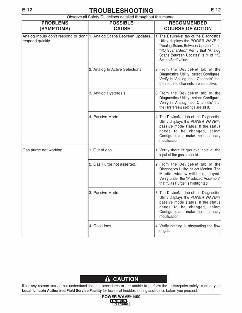
E-12TROUBLESHOOTINGE-12
POWER WAVE® i400
Observe all Safety Guidelines detailed throughout this manual
If for any reason you do not understand the test procedures or are unable to perform the tests/repairs safely, contact yourLocal Lincoln Authorized Field Service Facility for technical troubleshooting assistance before you proceed.
CAUTION
PROBLEMS(SYMPTOMS)
POSSIBLECAUSE
RECOMMENDEDCOURSE OF ACTION
Analog Inputs donʼt respond or donʼtrespond quickly.
Gas purge not working.
1. Analog Scans Between Updates.
2. Analog In Active Selections.
3. Analog Hysteresis.
4. Passive Mode.
1. Out of gas.
2. Gas Purge not asserted.
3. Passive Mode.
4. Gas Lines.
1. The DeviceNet tab of the DiagnosticsUtility displays the POWER WAVE®ʼs“Analog Scans Between Updates” and“I/O Scans/Sec.” Verify that “AnalogScans Between Updates” is ¼ of “I/OScans/Sec” value.
2. From the DeviceNet tab of theDiagnostics Utility, select Configure.Verify in “Analog Input Channels” thatthe required channels are set active.
3. From the DeviceNet tab of theDiagnostics Utility, select Configure.Verify in “Analog Input Channels” thatthe Hysteresis settings are all 0.
4. The DeviceNet tab of the DiagnosticsUtility displays the POWER WAVE®ʼspassive mode status. If the statusneeds to be changed, selectConfigure, and make the necessarymodification.
1. Verify there is gas available at theinput of the gas solenoid.
2. From the DeviceNet tab of theDiagnostics Utility, select Monitor. TheMonitor window will be displayed.Verify under the “Produced Assembly”that “Gas Purge” is highlighted.
3. The DeviceNet tab of the DiagnosticsUtility displays the POWER WAVE®ʼspassive mode status. If the statusneeds to be changed, selectConfigure, and make the necessarymodification.
4. Verify nothing is obstructing the flowof gas.
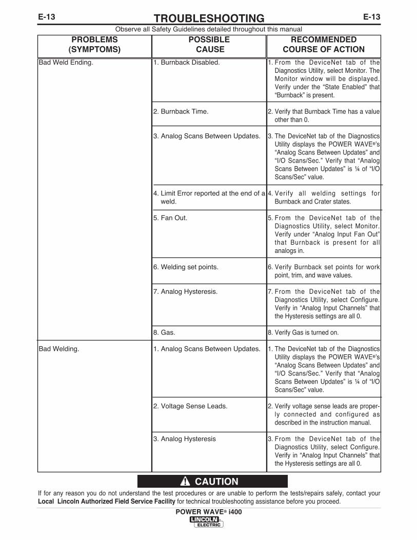
E-13TROUBLESHOOTINGE-13
POWER WAVE® i400
Observe all Safety Guidelines detailed throughout this manual
If for any reason you do not understand the test procedures or are unable to perform the tests/repairs safely, contact yourLocal Lincoln Authorized Field Service Facility for technical troubleshooting assistance before you proceed.
CAUTION
PROBLEMS(SYMPTOMS)
POSSIBLECAUSE
RECOMMENDEDCOURSE OF ACTION
Bad Weld Ending.
Bad Welding.
1. Burnback Disabled.
2. Burnback Time.
3. Analog Scans Between Updates.
4. Limit Error reported at the end of aweld.
5. Fan Out.
6. Welding set points.
7. Analog Hysteresis.
8. Gas.
1. Analog Scans Between Updates.
2. Voltage Sense Leads.
3. Analog Hysteresis
1. From the DeviceNet tab of theDiagnostics Utility, select Monitor. TheMonitor window will be displayed.Verify under the “State Enabled” that“Burnback” is present.
2. Verify that Burnback Time has a valueother than 0.
3. The DeviceNet tab of the DiagnosticsUtility displays the POWER WAVE®ʼs“Analog Scans Between Updates” and“I/O Scans/Sec.” Verify that “AnalogScans Between Updates” is ¼ of “I/OScans/Sec” value.
4. Verify all welding settings forBurnback and Crater states.
5. From the DeviceNet tab of theDiagnostics Utility, select Monitor.Verify under “Analog Input Fan Out”that Burnback is present for al lanalogs in.
6. Verify Burnback set points for workpoint, trim, and wave values.
7. From the DeviceNet tab of theDiagnostics Utility, select Configure.Verify in “Analog Input Channels” thatthe Hysteresis settings are all 0.
8. Verify Gas is turned on.
1. The DeviceNet tab of the DiagnosticsUtility displays the POWER WAVE®ʼs“Analog Scans Between Updates” and“I/O Scans/Sec.” Verify that “AnalogScans Between Updates” is ¼ of “I/OScans/Sec” value.
2. Verify voltage sense leads are proper-ly connected and configured asdescribed in the instruction manual.
3. From the DeviceNet tab of theDiagnostics Utility, select Configure.Verify in “Analog Input Channels” thatthe Hysteresis settings are all 0.

E-14TROUBLESHOOTINGE-14
POWER WAVE® i400
If for any reason you do not understand the test procedures or are unable to perform the tests/repairs safely, contact yourLocal Lincoln Authorized Field Service Facility for technical troubleshooting assistance before you proceed.
CAUTION
PROBLEMS(SYMPTOMS)
POSSIBLECAUSE
RECOMMENDEDCOURSE OF ACTION
ETHERNETCannot Connect.
Connection Drops while welding.
1. Physical connection.
2. IP address information.
3. Ethernet Speed.
1. Cable Location.
1. Verify that the correct patch cable orcross over cable is being used (referto local IT department for assis-tance).
NOTE:• For direct connection to the Fanuc
R30iA / R30iB Controller, use only thecable provided with the K2677-2Integration kit
• Verify the cables are fully insertedinto the bulk head connector.
• LED 8 located under the PC boardethernet connector will be lit whenthe machine is connected to anothernetwork device.
2. Use Weld Manager (included on thePOWER WAVE® Util i t ies andService Navigator CDʼs or availableat www.powerwavesoftware.com) toverify the correct IP address infor-mation has been entered.
NOTE:• The IP address configuration MUST
be set to dynamic when connected tothe Fanuc R30iA / R30iB Controller.
• Verify no duplicate the IP addressesexist on the network.
3. Verify that the network device con-nected to the POWER WAVE® iseither a 10-baseT device or a10/100-baseT device.
1. Verify Network cable is not locatednext to current carrying conductors.This would include input powercables and welding output cables.
PROBLEMS(SYMPTOMS)
POSSIBLECAUSE
RECOMMENDEDCOURSE OF ACTION
DeviceNet – PLC Controlled SystemBad Welding. 4. Limit Errors
5. Gas
6. Welding set points.
7. Wire Drive / Gear selection.
4. Verify all welding setpoint valuesare within limits.
5. Verify Gas remains on until afterthe weld is complete.
6. Verify welding set points for workpoint, trim, and wave values.
7. Verify proper wire drive and gearratio has been selected.
Observe all Safety Guidelines detailed throughout this manual
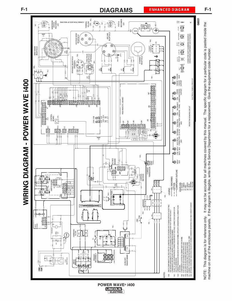
F-1DIAGRAMSF-1
POWER WAVE® i400
NO
TE
: T
his
diag
ram
is fo
r re
fere
nce
only
. It
may
not
be
accu
rate
for
all m
achi
nes
cove
red
by th
is m
anua
l. T
he s
peci
fic d
iagr
am fo
r a
part
icul
ar c
ode
is p
aste
d in
side
the
mac
hine
on
one
of th
e en
clos
ure
pane
ls.
If th
e di
agra
m is
ille
gibl
e, w
rite
to th
e S
ervi
ce D
epar
tmen
t for
a r
epla
cem
ent.
Giv
e th
e eq
uipm
ent c
ode
num
ber.
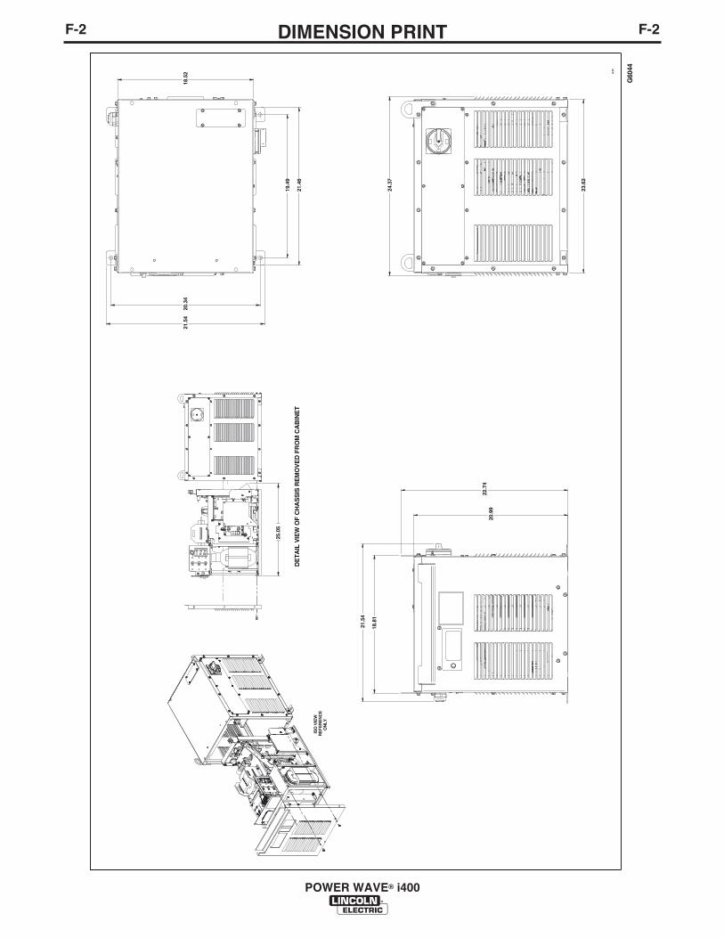
F-2DIMENSION PRINTF-2
POWER WAVE® i400
G60
44
A.0
1
20.3
4
19.4
9
21.5
4
21.4
6
23.6
2
22.7
420
.99
18.8
1
21.5
4
ISO
VIE
WR
EF
ER
EN
CE
ON
LY
25.0
5
DE
TAIL
VIE
W O
F C
HA
SS
IS R
EM
OV
ED
FR
OM
CA
BIN
ET
24.3
7
18.5
2
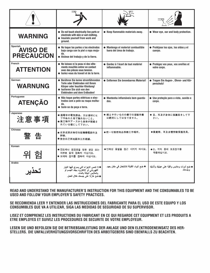
WARNING
AVISO DEPRECAUCION
ATTENTION
WARNUNG
ATENÇÃO
Spanish
French
German
Portuguese
Japanese
Chinese
Korean
Arabic
READ AND UNDERSTAND THE MANUFACTURER’S INSTRUCTION FOR THIS EQUIPMENT AND THE CONSUMABLES TO BEUSED AND FOLLOW YOUR EMPLOYER’S SAFETY PRACTICES.
SE RECOMIENDA LEER Y ENTENDER LAS INSTRUCCIONES DEL FABRICANTE PARA EL USO DE ESTE EQUIPO Y LOSCONSUMIBLES QUE VA A UTILIZAR, SIGA LAS MEDIDAS DE SEGURIDAD DE SU SUPERVISOR.
LISEZ ET COMPRENEZ LES INSTRUCTIONS DU FABRICANT EN CE QUI REGARDE CET EQUIPMENT ET LES PRODUITS AETRE EMPLOYES ET SUIVEZ LES PROCEDURES DE SECURITE DE VOTRE EMPLOYEUR.
LESEN SIE UND BEFOLGEN SIE DIE BETRIEBSANLEITUNG DER ANLAGE UND DEN ELEKTRODENEINSATZ DES HER-STELLERS. DIE UNFALLVERHÜTUNGSVORSCHRIFTEN DES ARBEITGEBERS SIND EBENFALLS ZU BEACHTEN.
Do not touch electrically live parts orelectrode with skin or wet clothing.Insulate yourself from work andground.
No toque las partes o los electrodosbajo carga con la piel o ropa moja-da.Aislese del trabajo y de la tierra.
Ne laissez ni la peau ni des vête-ments mouillés entrer en contactavec des pièces sous tension.Isolez-vous du travail et de la terre.
Berühren Sie keine stromführendenTeile oder Elektroden mit IhremKörper oder feuchter Kleidung!Isolieren Sie sich von denElektroden und dem Erdboden!
Não toque partes elétricas e elec-trodos com a pele ou roupa molha-da.Isole-se da peça e terra.
Keep flammable materials away.
Mantenga el material combustiblefuera del área de trabajo.
Gardez à l’écart de tout matérielinflammable.
Entfernen Sie brennbarres Material!
Mantenha inflamáveis bem guarda-dos.
Wear eye, ear and body protection.
Protéjase los ojos, los oídos y elcuerpo.
Protégez vos yeux, vos oreilles etvotre corps.
Tragen Sie Augen-, Ohren- und Kör-perschutz!
Use proteção para a vista, ouvido ecorpo.
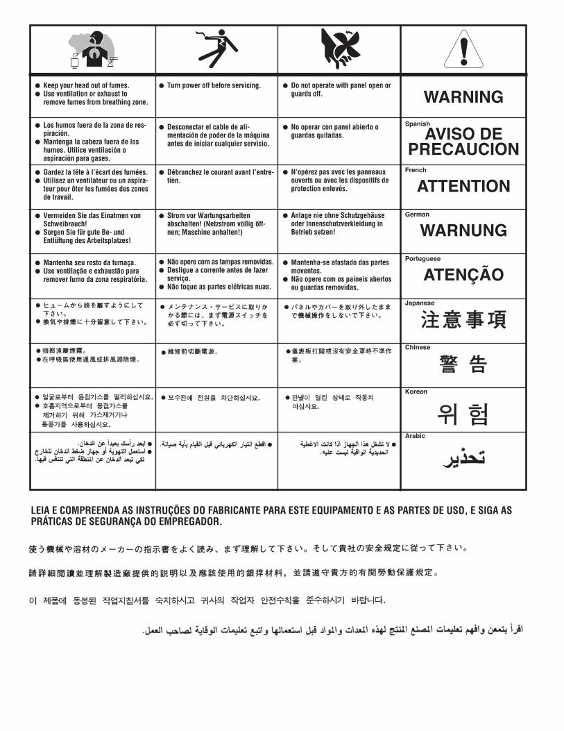
WARNING
AVISO DEPRECAUCION
ATTENTION
WARNUNG
ATENÇÃO
Spanish
French
German
Portuguese
Japanese
Chinese
Korean
Arabic
LEIA E COMPREENDA AS INSTRUÇÕES DO FABRICANTE PARA ESTE EQUIPAMENTO E AS PARTES DE USO, E SIGA ASPRÁTICAS DE SEGURANÇA DO EMPREGADOR.
Keep your head out of fumes.Use ventilation or exhaust toremove fumes from breathing zone.
Los humos fuera de la zona de res-piración.Mantenga la cabeza fuera de loshumos. Utilice ventilación oaspiración para gases.
Gardez la tête à l’écart des fumées.Utilisez un ventilateur ou un aspira-teur pour ôter les fumées des zonesde travail.
Vermeiden Sie das Einatmen vonSchweibrauch!Sorgen Sie für gute Be- undEntlüftung des Arbeitsplatzes!
Mantenha seu rosto da fumaça.Use ventilação e exhaustão pararemover fumo da zona respiratória.
Turn power off before servicing.
Desconectar el cable de ali-mentación de poder de la máquinaantes de iniciar cualquier servicio.
Débranchez le courant avant l’entre-tien.
Strom vor Wartungsarbeitenabschalten! (Netzstrom völlig öff-nen; Maschine anhalten!)
Não opere com as tampas removidas.Desligue a corrente antes de fazerserviço.Não toque as partes elétricas nuas.
Do not operate with panel open orguards off.
No operar con panel abierto oguardas quitadas.
N’opérez pas avec les panneauxouverts ou avec les dispositifs deprotection enlevés.
Anlage nie ohne Schutzgehäuseoder Innenschutzverkleidung inBetrieb setzen!
Mantenha-se afastado das partesmoventes.Não opere com os paineis abertosou guardas removidas.

Need Help?
Lincoln Electric “Rapid Response” Service!
Call 1.888.935.3877 to talk to a Service Representative
Hours of Operation: 8:00 AM to 6:00 PM (ET) Mon. thru Fri.
After hours? Use “Ask the Experts” at lincolnelectric.com
A Lincoln Service Representative will contact you no later than the following business day.
• For Service outside the USA: Email [email protected]
Cleveland, Ohio 44117-1199 USA TEL: 1.216.481.8100 FAX: 1.216.486.1751 WEB SITE: lincolnelectric.comFor Service in the USA and Canada: Call 1.888.935.3877 For Service outside the USA: Email [email protected]
• World's Leader in Welding and Cutting Products • • Sales and Service through Subsidiaries and Distributors Worldwide •
Copyright © Lincoln Global Inc.