im996 - lincoln electric
TRANSCRIPT
CLASSIC ® 300D KUBOTA
OPERATOR’S MANUAL
For Machines with Code Numbers 11547, 11548, 11642, 11643, 11811, 11812
IM996-BAugust, 2012
Safety Depends on YouLincoln arc welding and cuttingequipment is designed andbuilt with safety in mind.However, your overall safetycan be increased by properinstallation ... and thoughtfuloperation on your part. DONOT INSTALL, OPERATE ORREPAIR THIS EQUIPMENTWITHOUT READING THISMANUAL AND THE SAFETYPRECAUTIONS CONTAINEDTHROUGHOUT. And, mostimportantly, think before youact and be careful.
Cleveland, Ohio 44117-1199 USA TEL: 1.216.481.8100 FAX: 1.216.486.1751 WEB SITE: lincolnelectric.comFor Service in the USA and Canada: Call 1.888.935.3877 For Service outside the USA: Email [email protected]
• World's Leader in Welding and Cutting Products • • Sales and Service through Subsidiaries and Distributors Worldwide •
Copyright © Lincoln Global Inc.
FOR ENGINEpowered equipment.
1.a. Turn the engine off before troubleshooting and maintenancework unless the maintenance work requires it to be running.
____________________________________________________1.b. Operate engines in open, well-ventilated
areas or vent the engine exhaust fumes outdoors.
____________________________________________________1.c. Do not add the fuel near an open flame
welding arc or when the engine is running.Stop the engine and allow it to cool beforerefueling to prevent spilled fuel from vaporiz-ing on contact with hot engine parts andigniting. Do not spill fuel when filling tank. Iffuel is spilled, wipe it up and do not startengine until fumes have been eliminated.
____________________________________________________1.d. Keep all equipment safety guards, covers and devices in
position and in good repair.Keep hands, hair, clothing andtools away from V-belts, gears, fans and all other movingparts when starting, operating or repairing equipment.
____________________________________________________
1.e. In some cases it may be necessary to remove safetyguards to perform required maintenance. Removeguards only when necessary and replace them when themaintenance requiring their removal is complete.Always use the greatest care when working near movingparts.
___________________________________________________1.f. Do not put your hands near the engine fan.
Do not attempt to override the governor oridler by pushing on the throttle control rodswhile the engine is running.
___________________________________________________1.g. To prevent accidentally starting gasoline engines while
turning the engine or welding generator during maintenancework, disconnect the spark plug wires, distributor cap ormagneto wire as appropriate.
iSAFETYi
ARC WELDING CAN BE HAZARDOUS. PROTECT YOURSELF AND OTHERS FROM POSSIBLE SERIOUS INJURY OR DEATH.KEEP CHILDREN AWAY. PACEMAKER WEARERS SHOULD CONSULT WITH THEIR DOCTOR BEFORE OPERATING.
Read and understand the following safety highlights. For additional safety information, it is strongly recommended that youpurchase a copy of “Safety in Welding & Cutting - ANSI Standard Z49.1” from the American Welding Society, P.O. Box351040, Miami, Florida 33135 or CSA Standard W117.2-1974. A Free copy of “Arc Welding Safety” booklet E205 is availablefrom the Lincoln Electric Company, 22801 St. Clair Avenue, Cleveland, Ohio 44117-1199.
BE SURE THAT ALL INSTALLATION, OPERATION, MAINTENANCE AND REPAIR PROCEDURES AREPERFORMED ONLY BY QUALIFIED INDIVIDUALS.
WARNING
ELECTRIC AND MAGNETIC FIELDSmay be dangerous
2.a. Electric current flowing through any conductor causes localized Electric and Magnetic Fields (EMF). Welding current creates EMF fields around welding cables and welding machines
2.b. EMF fields may interfere with some pacemakers, andwelders having a pacemaker should consult their physicianbefore welding.
2.c. Exposure to EMF fields in welding may have other healtheffects which are now not known.
2.d. All welders should use the following procedures in order tominimize exposure to EMF fields from the welding circuit:
2.d.1. Route the electrode and work cables together - Securethem with tape when possible.
2.d.2. Never coil the electrode lead around your body.
2.d.3. Do not place your body between the electrode andwork cables. If the electrode cable is on your right side, the work cable should also be on your right side.
2.d.4. Connect the work cable to the workpiece as close aspossible to the area being welded.
2.d.5. Do not work next to welding power source.
1.h. To avoid scalding, do not remove theradiator pressure cap when the engine ishot.
CALIFORNIA PROPOSITION 65 WARNINGS
Diesel engine exhaust and some of its constituentsare known to the State of California to cause can-cer, birth defects, and other reproductive harm.
The engine exhaust from this product containschemicals known to the State of California to causecancer, birth defects, or other reproductive harm.
The Above For Diesel Engines The Above For Gasoline Engines
ARC RAYS can burn.4.a. Use a shield with the proper filter and cover
plates to protect your eyes from sparks andthe rays of the arc when welding or observingopen arc welding. Headshield and filter lensshould conform to ANSI Z87. I standards.
4.b. Use suitable clothing made from durable flame-resistantmaterial to protect your skin and that of your helpers fromthe arc rays.
4.c. Protect other nearby personnel with suitable, non-flammablescreening and/or warn them not to watch the arc nor exposethemselves to the arc rays or to hot spatter or metal.
ELECTRIC SHOCK cankill.3.a. The electrode and work (or ground) circuits
are electrically “hot” when the welder is on.Do not touch these “hot” parts with your bareskin or wet clothing. Wear dry, hole-free
gloves to insulate hands.
3.b. Insulate yourself from work and ground using dry insulation.Make certain the insulation is large enough to cover your fullarea of physical contact with work and ground.
In addition to the normal safety precautions, if weldingmust be performed under electrically hazardousconditions (in damp locations or while wearing wetclothing; on metal structures such as floors, gratings orscaffolds; when in cramped positions such as sitting,kneeling or lying, if there is a high risk of unavoidable oraccidental contact with the workpiece or ground) usethe following equipment:
• Semiautomatic DC Constant Voltage (Wire) Welder.• DC Manual (Stick) Welder.• AC Welder with Reduced Voltage Control.
3.c. In semiautomatic or automatic wire welding, the electrode,electrode reel, welding head, nozzle or semiautomaticwelding gun are also electrically “hot”.
3.d. Always be sure the work cable makes a good electricalconnection with the metal being welded. The connectionshould be as close as possible to the area being welded.
3.e. Ground the work or metal to be welded to a good electrical(earth) ground.
3.f. Maintain the electrode holder, work clamp, welding cable andwelding machine in good, safe operating condition. Replacedamaged insulation.
3.g. Never dip the electrode in water for cooling.
3.h. Never simultaneously touch electrically “hot” parts ofelectrode holders connected to two welders because voltagebetween the two can be the total of the open circuit voltageof both welders.
3.i. When working above floor level, use a safety belt to protectyourself from a fall should you get a shock.
3.j. Also see Items 6.c. and 8.
iiSAFETYii
FUMES AND GASEScan be dangerous.5.a. Welding may produce fumes and gases
hazardous to health. Avoid breathing thesefumes and gases. When welding, keepyour head out of the fume. Use enoughventilation and/or exhaust at the arc to keep
fumes and gases away from the breathing zone. Whenwelding with electrodes which require specialventilation such as stainless or hard facing (seeinstructions on container or MSDS) or on lead orcadmium plated steel and other metals or coatingswhich produce highly toxic fumes, keep exposure aslow as possible and within applicable OSHA PEL and ACGIH TLV limits using local exhaust or mechanicalventilation. In confined spaces or in some circum-stances, outdoors, a respirator may be required.Additional precautions are also required when weldingon galvanized steel.
5. b. The operation of welding fume control equipment is affectedby various factors including proper use and positioning ofthe equipment, maintenance of the equipment and the spe-cific welding procedure and application involved. Workerexposure level should be checked upon installation andperiodically thereafter to be certain it is within applicableOSHA PEL and ACGIH TLV limits.
5.c. Do not weld in locations near chlorinated hydrocarbon vaporscoming from degreasing, cleaning or spraying operations.The heat and rays of the arc can react with solvent vapors toform phosgene, a highly toxic gas, and other irritating prod-ucts.
5.d. Shielding gases used for arc welding can displace air andcause injury or death. Always use enough ventilation,especially in confined areas, to insure breathing air is safe.
5.e. Read and understand the manufacturerʼs instructions for thisequipment and the consumables to be used, including thematerial safety data sheet (MSDS) and follow youremployerʼs safety practices. MSDS forms are available fromyour welding distributor or from the manufacturer.
5.f. Also see item 1.b.
FOR ELECTRICALLYpowered equipment.
8.a. Turn off input power using the disconnectswitch at the fuse box before working onthe equipment.
8.b. Install equipment in accordance with the U.S. NationalElectrical Code, all local codes and the manufacturerʼsrecommendations.
8.c. Ground the equipment in accordance with the U.S. NationalElectrical Code and the manufacturerʼs recommendations.
CYLINDER may explodeif damaged.7.a. Use only compressed gas cylinders
containing the correct shielding gas for theprocess used and properly operatingregulators designed for the gas and
pressure used. All hoses, fittings, etc. should be suitable forthe application and maintained in good condition.
7.b. Always keep cylinders in an upright position securelychained to an undercarriage or fixed support.
7.c. Cylinders should be located:• Away from areas where they may be struck or subjected tophysical damage.
• A safe distance from arc welding or cutting operations andany other source of heat, sparks, or flame.
7.d. Never allow the electrode, electrode holder or any otherelectrically “hot” parts to touch a cylinder.
7.e. Keep your head and face away from the cylinder valve outletwhen opening the cylinder valve.
7.f. Valve protection caps should always be in place and handtight except when the cylinder is in use or connected foruse.
7.g. Read and follow the instructions on compressed gascylinders, associated equipment, and CGA publication P-l,“Precautions for Safe Handling of Compressed Gases inCylinders,” available from the Compressed Gas Association1235 Jefferson Davis Highway, Arlington, VA 22202.
WELDING and CUTTINGSPARKS cancause fire or explosion.6.a. Remove fire hazards from the welding area.
If this is not possible, cover them to preventthe welding sparks from starting a fire.
Remember that welding sparks and hotmaterials from welding can easily go through small cracksand openings to adjacent areas. Avoid welding nearhydraulic lines. Have a fire extinguisher readily available.
6.b. Where compressed gases are to be used at the job site,special precautions should be used to prevent hazardoussituations. Refer to “Safety in Welding and Cutting” (ANSIStandard Z49.1) and the operating information for theequipment being used.
6.c. When not welding, make certain no part of the electrodecircuit is touching the work or ground. Accidental contactcan cause overheating and create a fire hazard.
6.d. Do not heat, cut or weld tanks, drums or containers until theproper steps have been taken to insure that such procedureswill not cause flammable or toxic vapors from substancesinside. They can cause an explosion even though they havebeen “cleaned”. For information, purchase “RecommendedSafe Practices for the Preparation for Welding and Cutting ofContainers and Piping That Have Held HazardousSubstances”, AWS F4.1 from the American Welding Society(see address above).
6.e. Vent hollow castings or containers before heating, cutting orwelding. They may explode.
6.f. Sparks and spatter are thrown from the welding arc. Wear oilfree protective garments such as leather gloves, heavy shirt,cuffless trousers, high shoes and a cap over your hair. Wearear plugs when welding out of position or in confined places.Always wear safety glasses with side shields when in awelding area.
6.g. Connect the work cable to the work as close to the weldingarea as practical. Work cables connected to the buildingframework or other locations away from the welding areaincrease the possibility of the welding current passingthrough lifting chains, crane cables or other alternate cir-cuits. This can create fire hazards or overheat lifting chainsor cables until they fail.
6.h. Also see item 1.c.
6.I. Read and follow NFPA 51B “ Standard for Fire PreventionDuring Welding, Cutting and Other Hot Work”, availablefrom NFPA, 1 Batterymarch Park, PO box 9101, Quincy, Ma022690-9101.
6.j. Do not use a welding power source for pipe thawing.
iiiSAFETYiii
Refer to http://www.lincolnelectric.com/safety for additional safety information.
ivSAFETYiv
PRÉCAUTIONS DE SÛRETÉPour votre propre protection lire et observer toutes les instructionset les précautions de sûreté specifiques qui parraissent dans cemanuel aussi bien que les précautions de sûreté générales suiv-antes:
Sûreté Pour Soudage A LʼArc1. Protegez-vous contre la secousse électrique:
a. Les circuits à lʼélectrode et à la piéce sont sous tensionquand la machine à souder est en marche. Eviter toujourstout contact entre les parties sous tension et la peau nueou les vétements mouillés. Porter des gants secs et sanstrous pour isoler les mains.
b. Faire trés attention de bien sʼisoler de la masse quand onsoude dans des endroits humides, ou sur un planchermetallique ou des grilles metalliques, principalement dans les positions assis ou couché pour lesquelles une grandepartie du corps peut être en contact avec la masse.
c. Maintenir le porte-électrode, la pince de masse, le câblede soudage et la machine à souder en bon et sûr étatdefonctionnement.
d.Ne jamais plonger le porte-électrode dans lʼeau pour lerefroidir.
e. Ne jamais toucher simultanément les parties sous tensiondes porte-électrodes connectés à deux machines à souderparce que la tension entre les deux pinces peut être letotal de la tension à vide des deux machines.
f. Si on utilise la machine à souder comme une source decourant pour soudage semi-automatique, ces precautionspour le porte-électrode sʼapplicuent aussi au pistolet desoudage.
2. Dans le cas de travail au dessus du niveau du sol, se protégercontre les chutes dans le cas ou on recoit un choc. Ne jamaisenrouler le câble-électrode autour de nʼimporte quelle partiedu corps.
3. Un coup dʼarc peut être plus sévère quʼun coup de soliel,donc:
a. Utiliser un bon masque avec un verre filtrant appropriéainsi quʼun verre blanc afin de se protéger les yeux du ray-onnement de lʼarc et des projections quand on soude ouquand on regarde lʼarc.
b. Porter des vêtements convenables afin de protéger lapeau de soudeur et des aides contre le rayonnement delʻarc.
c. Protéger lʼautre personnel travaillant à proximité ausoudage à lʼaide dʼécrans appropriés et non-inflammables.
4. Des gouttes de laitier en fusion sont émises de lʼarc desoudage. Se protéger avec des vêtements de protection libresde lʼhuile, tels que les gants en cuir, chemise épaisse, pan-talons sans revers, et chaussures montantes.
5. Toujours porter des lunettes de sécurité dans la zone desoudage. Utiliser des lunettes avec écrans lateraux dans leszones où lʼon pique le laitier.
6. Eloigner les matériaux inflammables ou les recouvrir afin deprévenir tout risque dʼincendie dû aux étincelles.
7. Quand on ne soude pas, poser la pince à une endroit isolé dela masse. Un court-circuit accidental peut provoquer unéchauffement et un risque dʼincendie.
8. Sʼassurer que la masse est connectée le plus prés possiblede la zone de travail quʼil est pratique de le faire. Si on placela masse sur la charpente de la construction ou dʼautresendroits éloignés de la zone de travail, on augmente le risquede voir passer le courant de soudage par les chaines de lev-age, câbles de grue, ou autres circuits. Cela peut provoquerdes risques dʼincendie ou dʼechauffement des chaines et descâbles jusquʼà ce quʼils se rompent.
9. Assurer une ventilation suffisante dans la zone de soudage.Ceci est particuliérement important pour le soudage de tôlesgalvanisées plombées, ou cadmiées ou tout autre métal quiproduit des fumeés toxiques.
10. Ne pas souder en présence de vapeurs de chlore provenantdʼopérations de dégraissage, nettoyage ou pistolage. Lachaleur ou les rayons de lʼarc peuvent réagir avec les vapeursdu solvant pour produire du phosgéne (gas fortement toxique)ou autres produits irritants.
11. Pour obtenir de plus amples renseignements sur la sûreté,voir le code “Code for safety in welding and cutting” CSAStandard W 117.2-1974.
PRÉCAUTIONS DE SÛRETÉ POURLES MACHINES À SOUDER ÀTRANSFORMATEUR ET ÀREDRESSEUR
1. Relier à la terre le chassis du poste conformement au code delʼélectricité et aux recommendations du fabricant. Le dispositifde montage ou la piece à souder doit être branché à unebonne mise à la terre.
2. Autant que possible, Iʼinstallation et lʼentretien du poste seronteffectués par un électricien qualifié.
3. Avant de faires des travaux à lʼinterieur de poste, la debranch-er à lʼinterrupteur à la boite de fusibles.
4. Garder tous les couvercles et dispositifs de sûreté à leurplace.
vv
Thank You for selecting a QUALITY product by Lincoln Electric. We want youto take pride in operating this Lincoln Electric Company product••• as much pride as we have in bringing this product to you!
Read this Operators Manual completely before attempting to use this equipment. Save this manual and keep ithandy for quick reference. Pay particular attention to the safety instructions we have provided for your protection.The level of seriousness to be applied to each is explained below:
WARNINGThis statement appears where the information must be followed exactly to avoid serious personal injury or loss of life.
This statement appears where the information must be followed to avoid minor personal injury or damage to this equipment.
CAUTION
Please Examine Carton and Equipment For Damage ImmediatelyWhen this equipment is shipped, title passes to the purchaser upon receipt by the carrier. Consequently, Claimsfor material damaged in shipment must be made by the purchaser against the transportation company at thetime the shipment is received.
Please record your equipment identification information below for future reference. This information can befound on your machine nameplate.
Product _________________________________________________________________________________
Model Number ___________________________________________________________________________
Code Number or Date Code_________________________________________________________________
Serial Number____________________________________________________________________________
Date Purchased___________________________________________________________________________
Where Purchased_________________________________________________________________________
Whenever you request replacement parts or information on this equipment, always supply the information youhave recorded above. The code number is especially important when identifying the correct replacement parts.
CUSTOMER ASSISTANCE POLICYThe business of The Lincoln Electric Company is manufacturing and selling high quality welding equipment, consumables, and cutting equip-ment. Our challenge is to meet the needs of our customers and to exceed their expectations. On occasion, purchasers may ask LincolnElectric for advice or information about their use of our products. We respond to our customers based on the best information in our posses-sion at that time. Lincoln Electric is not in a position to warrant or guarantee such advice, and assumes no liability, with respect to such infor-mation or advice. We expressly disclaim any warranty of any kind, including any warranty of fitness for any customerʼs particular purpose,with respect to such information or advice. As a matter of practical consideration, we also cannot assume any responsibility for updating orcorrecting any such information or advice once it has been given, nor does the provision of information or advice create, expand or alter anywarranty with respect to the sale of our products.
Lincoln Electric is a responsive manufacturer, but the selection and use of specific products sold by Lincoln Electric is solely within the controlof, and remains the sole responsibility of the customer. Many variables beyond the control of Lincoln Electric affect the results obtained inapplying these types of fabrication methods and service requirements.
Subject to Change – This information is accurate to the best of our knowledge at the time of printing. Please refer to www.lincolnelectric.comfor any updated information.
On-Line Product Registration- Register your machine with Lincoln Electric either via fax or over the Internet.• For faxing: Complete the form on the back of the warranty statement included in the literature packet
accompanying this machine and fax the form per the instructions printed on it.• For On-Line Registration: Go to our WEB SITE at www.lincolnelectric.com. Choose “Support” and then “Register
Your Product”. Please complete the form and submit your registration.
vi vi TABLE OF CONTENTSPage
Installation .......................................................................................................Section ATechnical Specifications ........................................................................................A-1General Description ...............................................................................................A-2Design Features ....................................................................................................A-2Pre-Operation Installation ......................................................................................A-3
Safety Precautions ..........................................................................................A-3Exhaust Spark Arrester ...................................................................................A-3Location/Ventilation.........................................................................................A-3Machine Grounding.........................................................................................A-3Lift Bail ............................................................................................................A-3Trailers ............................................................................................................A-4Polarity Control and Cable Sizes ....................................................................A-4
Pre-Operation Service ...........................................................................................A-4Oil ....................................................................................................................A-4Fuel .................................................................................................................A-4Cooling System ...............................................................................................A-4Battery Charging .............................................................................................A-5
________________________________________________________________________Operation .........................................................................................................Section B
Engine Operation...................................................................................................B-1Starting The Kubota V2403M Engine.............................................................B-1Cold Weather Starting.....................................................................................B-1High Altitude Operation ...................................................................................B-1Stopping the engine ........................................................................................B-1Break-In...........................................................................................................B-1
Welder Operation...................................................................................................B-2Duty Cycle.......................................................................................................B-2Control of Welding Current..............................................................................B-2Idler Operation ................................................................................................B-3Auxiliary Power ...............................................................................................B-3Fuel Consumption Data ..................................................................................B-3
________________________________________________________________________Accessories .....................................................................................................Section C
Optional Features (Field Installed) ........................................................................C-1________________________________________________________________________
Maintenance ....................................................................................................Section DSafety Precautions ................................................................................................D-1General Instructions ..............................................................................................D-1Cooling System .....................................................................................................D-1Bearings ................................................................................................................D-1Commutator and Brushes .....................................................................................D-1Idler Maintenance..................................................................................................D-2Nameplates ...........................................................................................................D-2Purging Air from Fuel System................................................................................D-2Engine Service Chart ............................................................................................D-3GFCI Module Testing and Restting Procedure......................................................D-4
________________________________________________________________________Troubleshooting ..............................................................................................Section E
Safety Precautions.................................................................................................E-1Welder Troubleshooting ........................................................................................E-2Electronic Idler Troubleshooting Guide...........................................................E-3,E-4Engine Troubleshooting Guide ...............................................................E-5, E-6,E-7
________________________________________________________________________Diagrams ..........................................................................................................Section F
Wiring Diagrams ..............................................................................F-1, F-2, F-3, F-4Dimension Print......................................................................................................F-5
________________________________________________________________________Parts List.............................................................................P-231, P-595, P-682, Series
INSTALLATION
CLASSIC® 300D KUBOTA
A-1A-1
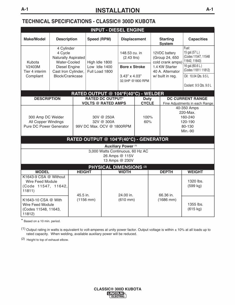
TECHNICAL SPECIFICATIONS - CLASSIC® 300D KUBOTA
Make/Model Description Speed (RPM) Displacement Starting CapacitiesSystem
4 Cylinder4 Cycle 148.53 cu. in 12VDC battery
Naturally Aspirated (2.43 ltrs) (Group 24, 650Kubota Water-Cooled High Idle 1800 cold crank amps)V2403M Diesel Engine Low Idle 1400 Bore x Stroke 1.4 KW Starter
Tier 4 interim Cast Iron Cylinder, Full Load 1800 40 A. AlternatorCompliant Block/Crankcase 3.43” x 4.03” w/ built in reg. Oil: 10.04 Qts. 9.5 L
32.5HP @1800 RPMCoolant: 9.5 Qts. 9.0 L
INPUT - DIESEL ENGINE
RATED OUTPUT @ 104°F(40°C) - WELDER
MODEL HEIGHT WIDTH DEPTH WEIGHT
1320 lbs. (599 kg)
45.5 in. 24.00 in. 66.36 in.(1156 mm) (610 mm) (1686 mm)
1355 lbs. (615 kg)
RATED OUTPUT @ 104°F(40°C) - GENERATOR
DESCRIPTION RATED DC OUTPUT* Duty DC CURRENT RANGEVOLTS @ RATED AMPS CYCLE Fine Adjustments in each Range
40-350 Amps220-Max.
300 Amp DC Welder 30V @ 250A 100% 160-240All Copper Windings 32V @ 300A 60% 120-190
Pure DC Power Generator 99V DC Max. OCV @ 1800RPM 80-130Min.-90
Auxiliary Power (1)
3,000 Watts Continuous, 60 Hz AC26 Amps @ 115V13 Amps @ 230V
PHYSICAL DIMENSIONS (2)
* Based on a 10 min. period.
(1) Output rating in watts is equivalent to volt-amperes at unity power factor. Output voltage is within ± 10% at all loads up torated capacity. When welding, available auxiliary power will be reduced.
(2) Height to top of exhaust elbow.
K1643-9 CSA @ WithoutWire Feed Module
(Code 11547, 11642,11811)
K1643-10 CSA @ WithWire Feed Module(Codes 11548, 11643,11812)
Fuel: 15 gal.(57 L.)(Codes 11547, 1154811642, 11643)16 gal.(60.6 L.)(Codes 11811 11812)
A-2INSTALLATION
CLASSIC® 300D KUBOTA
A-2
GENERAL DESCRIPTION
The CLASSIC® 300D KUBOTA is a heavy duty, engine driven,DC arc welding power source, capable of providing constantcurrent output for stick welding or DC TIG welding. This welderis wound with all copper coils, rated at 300 amps/32 Volts, andprovides other Classic® features such as improved door latchesand stainless hinges. With the addition of the optional K623-1
Wire Feed Module™, the CLASSIC® 300D KUBOTA will pro-vide constant voltage output for running the LN-7, LN-23P, orLN-25 wire feeders. (The Wire Feed Module is factory installedon the K1643-10). The optional K924-4 Remote Control Kit, pro-vides a remote control rheostat for remote fine current and opencircuit voltage adjustment. See Section C for description.
The CLASSIC® 300D KUBOTA has an Electronic EngineProtection System. In the event of sudden low oil pressure orhigh coolant temperature, the engine immediately shuts down.The CLASSIC® 300D KUBOTA has a current range of 40-350DC amps with output ratings as follows:These units are also capable of providing 3 kVA of 115/230volts of 60 cycle AC auxiliary power.
The CLASSIC® 300D KUBOTA uses the Kubota V2403Mindustrial water-cooled diesel engine.
DESIGN FEATURESControl Panel
Both the engine and the welder controls are located on onerecessed panel at the exciter end of the machine. The weldercontrols consist of a five step “Current Range Selector” switchand a “Fine Current Adjustment” rheostat. The welder isequipped with a “Start” button, an “Ignition” switch, an “Idler”control switch, and a “Glow Plug” button for easier cold weatherstarting.
The control panel also contains an engine temperature gauge, abattery charging ammeter, an oil pressure gauge, for auxiliarypower consists of one 20 amp, 120VAC (5-20R) duplex recep-tacle with GFCI protection and one 15 amp, 250VAC (6-15R)receptacle, protected by 2 pole, 15 Amp breaker.
All Copper Windings - For long life and dependable operation.
Engine Idler - The Classic® 300D is equipped with an elec-tronic automatic engine idler. It automatically increases anddecreases engine speed when starting and stopping weldingor using auxiliary power. A built-in time delay permits chang-ing electrodes before the engine slows to its low idle speed.The “Idler” control switch on the panel locks the idler in high idleposition when desired.
Auxiliary Power - 3.0 kVA of nominal 115/230V, 60Hz, AC.Output voltage is maintained within ± 10% at all loads up torated capacity. (See Optional Features for Power Plug Kit.)
GFCI - Protects the 20 amp, 120V duplex receptacle. Seethe Maintenance Section for detailed information on testingand resetting of the GFCI.
120 V DUPLEX RECEPTACLE AND GFCI
A GFCI protects the 120V auxiliary powerreceptacle.
A GFCI (Ground Fault Circuit Interrupter) is a device to protectagainst electric shock should a piece of defective equipmentconnected to it develop a ground fault. If this situation shouldoccur, the GFCI will trip, removing voltage from the output ofthe receptacle. If a GFCI is tripped see the MAINTENANCEsection for detailed information on testing and resetting it. AGFCI should be properly tested at least once every month.
The 120 V auxiliary power receptacle should only be used withthree wire grounded type plugs or approved double insulatedtools with two wire plugs. The current rating of any plug usedwith the system must be at least equal to the current capacity ofthe associated receptacle.
Welder Enclosure - The complete welder is rubber mounted ona rugged steel “C” channel base.
The output terminals are placed at the side of the machines sothat they are protected by the door. The output terminals arelabeled (+) and (-).
Cranking System - A 12 volt electric starter is standard.
Air Cleaner - Heavy duty two stage dry type.
Muffler - A muffler and stainless steel exhaust outlet elbow arestandard.
Engine Hour Meter - A meter to record hours of operation.
Engine Protection - The system shuts the engine down in theevent of sudden low oil pressure or high coolant temperature. Awarning light on the control panel will indicate such a fault. Toreset the engine for restarting, turn the ignition switch off thenon. Refer to Troubleshooting section for all warning light faultcodes.
High Idle RPM (OCV) Adjustment - A Potentiometer is mount-ed on the Control Panel that allows the operator to adjust thehigh idle engine speed between 1650 and 1800 RPMʼS. This isto allow further adjustment of the OCV. Total OCV adjustmentrange is about 15 volts.
Oil Drain Valve - A ball valve, hose and clamp are standard.
Remote Control - The Remote/Local switch and Receptacleare standard.
250A @ 30V300A @ 32V
100%60%
RATED OUTPUT DUTY CYCLE
A-3INSTALLATION
CLASSIC® 300D KUBOTA
A-3
PRE-OPERATION INSTALLATION
EXHAUST SPARK ARRESTERSome federal, state or local laws may require that enginesbe equipped with exhaust spark arresters when they areoperated in certain locations where unarrested sparks maypresent a fire hazard. The standard muffler included withthis welder does not qualify as a spark arrester. Whenrequired by local regulations, a suitable spark arrester mustbe installed and properly maintained.
Use of an incorrect arrester may lead to engine damage orperformance loss. Contact the engine manufacturer for spe-cific recommendations.--------------------------------------------------------------------------------LOCATION/VENTILATIONAlways operate the welder with the doors closed. Leaving thedoors open changes the designed air flow and may causeoverheating.
The welder should be located to provide an unrestricted flowof clean, cool air. Also, locate the welder so that engineexhaust fumes are properly vented to an outside area.
ANGLE OF OPERATIONEngines are designed to run in the level condition which iswhere the optimum performance is achieved. The maximumangle of continuous operation is 20 degrees in all directions,30 degrees Intermittent (less than 10 minutes continuous) inall directions.
If the engine is to be operated at an angle, provisions must bemade for checking and maintaining the oil level at the normal(FULL) oil capacity in the crankcase.
When operating the welder at an angle, the effective fuelcapacity will be slightly less than the amount specified.
MACHINE GROUNDING
According to the United States National Electrical Code, theframe of this portable generator is not required to be groundedand is permitted to serve as the grounding means for cordconnected equipment plugged into its receptacle.
Some state, local, or other codes or unusual operating circum-stances may require the machine frame to be grounded. It isrecommended that you determine the extent to which suchrequirements may apply to your particular situation and followthem explicitly. A machine grounding stud marked with thesymbol is provided on the welding generator frame foot. Ingeneral, if the machine is to be grounded, it should be con-nected with a #8 or larger copper wire to a solid earth groundsuch as a metal water pipe going into the ground for at leastten feet and having no insulated joints, or to the metal frame-work of a building which has been effectively grounded. TheU.S. National Code lists a number of alternate means ofgrounding electrical equipment.
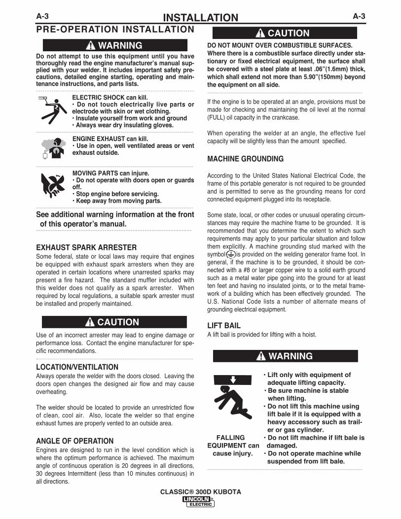
LIFT BAILA lift bail is provided for lifting with a hoist.
Do not attempt to use this equipment until you havethoroughly read the engine manufacturerʼs manual sup-plied with your welder. It includes important safety pre-cautions, detailed engine starting, operating and main-tenance instructions, and parts lists.------------------------------------------------------------------------
ELECTRIC SHOCK can kill.• Do not touch electrically live parts orelectrode with skin or wet clothing.• Insulate yourself from work and ground• Always wear dry insulating gloves.
--------------------------------------------------------------------------------ENGINE EXHAUST can kill.• Use in open, well ventilated areas or ventexhaust outside.
--------------------------------------------------------------------------------MOVING PARTS can injure.• Do not operate with doors open or guardsoff.• Stop engine before servicing.• Keep away from moving parts.
--------------------------------------------------------------------------------See additional warning information at the frontof this operatorʼs manual.
-----------------------------------------------------------------
WARNING
CAUTION
DO NOT MOUNT OVER COMBUSTIBLE SURFACES. Where there is a combustible surface directly under sta-tionary or fixed electrical equipment, the surface shallbe covered with a steel plate at least .06”(1.6mm) thick,which shall extend not more than 5.90”(150mm) beyondthe equipment on all side.-------------------------------------------------------------------------------
CAUTION
• Lift only with equipment ofadequate lifting capacity.
• Be sure machine is stablewhen lifting.
• Do not lift this machine usinglift bale if it is equipped with aheavy accessory such as trail-er or gas cylinder.
FALLING • Do not lift machine if lift bale is EQUIPMENT can damaged.
cause injury. • Do not operate machine whilesuspended from lift bale.
-------------------------------------------------------------------------------
WARNING

PRE-OPERATION SERVICEREAD the engine operating and maintenance instruc-tions supplied with this machine.------------------------------------------------------------------------
OIL
This unit is supplied from the factory with the enginecrankcase filled with a high quality SAE 10W/30 oil.This oil should be acceptable for most typical ambienttemperatures. Consult the engine operation manualfor specific engine manufacturerʼs recommendations.Upon receipt of the welder, check the engine dipstickto be sure the oil is at the “full” mark. DO NOT overfill.
FUEL
Fill the fuel tank with the grade of fuel recommendedin the Engine Operatorʼs manual. Make sure the valveon the water separator is in the open position.
COOLING SYSTEM
The radiator has been filled at the factory with a 50-50mixture of ethylene glycol antifreeze and water.Check the radiator level and add a 50-50 solution asneeded (see engine manual or antifreeze container foralternate antifreeze recommendations).
CAUTION
A-4INSTALLATION
CLASSIC® 300D KUBOTA
A-4
TRAILER (See Optional Features)
If the user adapts a non-Lincoln trailer, the user mustassume responsibility that the method of attachmentand usage does not result in a safety hazard nor dam-age the welding equipment. Some of the factors to beconsidered are as follows:1. Design capacity of trailer vs. weight of Lincoln
equipment and likely additional attachments.2. Proper support of, and attachment to, the base of
the welding equipment so there will be no unduestress to the framework.
3. Proper placement of the equipment on the trailer toensure stability side to side and front to back whenbeing moved and when standing by itself whilebeing operated or serviced.
4. Typical conditions of use, i.e., travel speed, rough-ness of surface on which the trailer will be operat-ed; environmental conditions, likely maintenance.
5. Conformance with federal, state and local laws. (1)(1) Consult your federal, state and local laws regarding specificrequirements for use on public highways.
POLARITY CONTROL AND CABLE SIZES
With the engine off, route the electrode and workcables through the strain relief bracket on the baseand connect to the studs located below the fuel tankmounting rail. (See size recommendations below.)For positive polarity, connect the electrode cable tothe terminal marked “+”. For Negative polarity, con-nect the electrode cable to the “-” stud. These con-nections should be checked periodically and tightenedif necessary.
When welding at a considerable distance from thewelder, be sure you use ample sized welding cables.
RECOMMENDED COPPER CABLE SIZESCables Sizes for Combined Lengthof Electrode Plus Work Cable
Amps Duty Cycle Up to 200ft.(61m) 200 to 250ft.(61 to 76m)
250 100% 1 1/0
300 60% 1/0 2/0
VEHICLE MOUNTING
Improperly mounted concentrated loads maycause unstable vehicle handling and tires or othercomponents to fail.
• Only transport this Equipment on serviceablevehicles which are rated and designed for suchloads.
• Distribute, balance and secure loads so vehicleis stable under conditions of use.
• Do not exceed maximum rated loads for compo-nents such as suspension, axles and tires.
• Mount equipment base to metal bed or frame ofvehicle.
• Follow vehicle manufactureʼs instructions.-------------------------------------------------------------------------------
WARNING
• Stop engine while fueling.• Do not smoke when fueling.• Keep sparks and flame away from
tank.• Do not leave unattended while
fueling.• Wipe up spilled fuel and allow
fumes to clear before startingengine.
• Do not overfill tank, fuel expan-sion may cause overflow.
DIESEL FUEL ONLY-Low sulphur fuel or ultra lowsulphur fuel in U.S.A. and Canada.-------------------------------------------------------------------------
WARNING
DIESEL FUELcan
cause fire
A-5INSTALLATION
CLASSIC® 300D KUBOTA
A-5
Battery Charging
The CLASSIC® 300D KUBOTA is equipped with awet charged battery. The charging current is automat-ically regulated when the battery is low (after startingthe engine) to a trickle current when the battery is fullycharged.
When replacing, jumping or otherwise connecting thebattery to the battery cables, the proper polarity mustbe observed. This system is NEGATIVE GROUND.
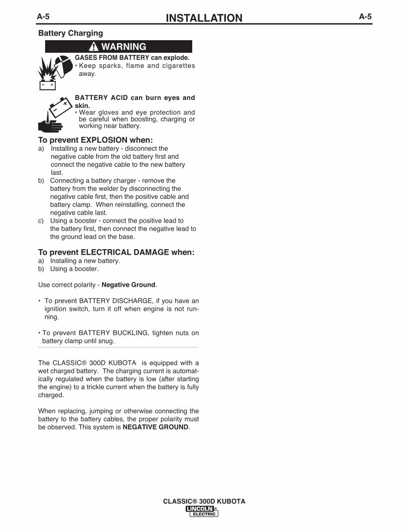
GASES FROM BATTERY can explode.• Keep sparks, flame and cigarettes
away.
BATTERY ACID can burn eyes andskin.• Wear gloves and eye protection and
be careful when boosting, charging orworking near battery.
To prevent EXPLOSION when:a) Installing a new battery - disconnect the
negative cable from the old battery first and connect the negative cable to the new battery last.
b) Connecting a battery charger - remove the battery from the welder by disconnecting the negative cable first, then the positive cable and battery clamp. When reinstalling, connect the negative cable last.
c) Using a booster - connect the positive lead to the battery first, then connect the negative lead to the ground lead on the base.
To prevent ELECTRICAL DAMAGE when:a) Installing a new battery.b) Using a booster.
Use correct polarity - Negative Ground.
• To prevent BATTERY DISCHARGE, if you have anignition switch, turn it off when engine is not run-ning.
• To prevent BATTERY BUCKLING, tighten nuts onbattery clamp until snug.
------------------------------------------------------------------------
WARNING
B-1OPERATIONB-1
ENGINE OPERATION
Operate the welder with the doors closed. Leaving thedoors open changes the designed air flow and cancause overheating.
STARTING THE CLASSIC® 300D KUBOTA V2403MDIESEL ENGINE
1. Turn the “IDLER” switch to “HIGH”.2. Turn the “IGNITION” switch to “ON”.3. Press the Glow Plug button for 20 to 30 seconds.
(maximum 60 seconds).4. Press the Glow Plug button and the Start button at the
same time. When the engine starts running, releaseboth buttons. If the engine fails to start in 20 seconds,wait 30 seconds and repeat the above procedure.
5. Observe the oil pressure. If no pressure shows within30 seconds, stop the engine and consult the engineoperating manual. To stop the engine, turn the “IGNI-TION” switch to “OFF”.
6. If the engine protection warning light comes on duringcranking or after start up, the “IGNITION” switch mustbe turned “OFF” to reset the engine protection system.
7. Allow the engine to run at high idle speed for severalminutes to warm the engine. Stop the engine andrecheck the oil level, after allowing sufficient time forthe oil to drain into the pan. If the level is down, fill it tothe full mark again. The engine controls were properlyset at the factory and should require no adjusting whenreceived.
CLASSIC® 300D KUBOTA
Do not attempt to use this equipment until youhave thoroughly read the engine manufacturerʼsmanual supplied with your welder. It includesimportant safety precautions, detailed enginestarting, operating and maintenance instructions,and parts lists.----------------------------------------------------------------
ELECTRIC SHOCK can kill.• Do not touch electrically live parts orelectrode with skin or wet clothing.• Insulate yourself from work andground• Always wear dry insulating gloves.
------------------------------------------------------------------------ENGINE EXHAUST can kill.• Use in open, well ventilated areas orvent exhaust outside.
------------------------------------------------------------------------MOVING PARTS can injure.• Do not operate with doors open orguards off.• Stop engine before servicing.• Keep away from moving parts.
------------------------------------------------------------------------See additional warning information at thefront of this operatorʼs manual.
------------------------------------------------------------
WARNING
COLD WEATHER STARTING:
With a fully charged battery and the proper weight oil,the engine should start satisfactorily even down toabout -5°F (-20°C), it maybe desirable to install cold-starting aides.
Note: Extreme cold weather staring may requirelonger glow plug operation.
Under NO conditions should ether or otherstarting fluids be used!-------------------------------------------------------------------------------HIGH ALTITUDE OPERATION:
At higher altitudes, output derating may be necessary.For maximum rating, derate the welder 4% for every300 meters (984 ft.) above 1500 meters (4920 ft.).
Contact a Kubota Service Representative for anyengine adjustments that may be required.
STOPPING THE ENGINE
1. Turn the “IGNITION” switch to “OFF”
At the end of each dayʼs welding, check the crankcaseoil level, drain accumulated dirt and water from thewater separator and refill the fuel tank to minimizemoisture condensation in the tank. Also, running outof fuel tends to draw dirt into the fuel system.
When hauling the welder between job sites, close thevalve on the water separator.
If the fuel supply is cut off or runs out while the fuelpump is operating, air may be entrapped in the fueldistribution system. If this happens, bleeding of thefuel system may be necessary. Use qualified person-nel to do this per the instructions in the MAINTE-NANCE section of this manual.
ENGINE BREAK-IN
Lincoln Electric selects high quality, heavy-duty indus-trial engines for the portable welding machines weoffer. While it is normal to see a small amount ofcrankcase oil consumption during initial operation,excessive oil use, wet stacking (oil or tar like sub-stance at the exhaust port), or excessive smoke is notnormal.
WARNING
B-2OPERATIONB-2
CLASSIC® 300D KUBOTA
WELDER OPERATION
------------------------------------------------------------------------
DUTY CYCLE
The NEMA output rating of the CLASSIC® 300DKUBOTA is 300 amperes at 32 arc volts on a 60%duty cycle (consult Specifications in this manual foralternate ratings). Duty cycle is based on a ten minuteperiod; thus, the welder can be loaded at rated outputfor six minutes out of every ten minute period.
CONTROL OF WELDING CURRENT
DO NOT TURN THE “CURRENT RANGE SELEC-TOR” WHILE WELDING because the current mayarc between the contacts and damage the switch.------------------------------------------------------------------------
The “Current Range Selector” provides five overlap-ping current ranges. The “Fine Current Adjustment”adjusts the current from minimum to maximum withineach range. Open circuit voltage is also controlled bythe “Fine Current Adjustment” permitting control of thearc characteristics.
A high open circuit voltage setting provides the soft“buttering” arc with best resistance to pop-outs pre-ferred for most welding. To get this characteristic, setthe “Current Range Selector” to the lowest setting thatstill provides the current you need and set the “FineCurrent Adjustment” near maximum. For example: toobtain 175 amps and a soft arc, set the “CurrentRange Selector” to the 190-120 position and thenadjust the “Fine Current Adjustment” for 175 amps.
When a forceful “digging” arc is required, usually forvertical and overhead welding, use a higher “CurrentRange Selector” setting and lower open circuit volt-age. For example: to obtain 175 amps and a forcefularc, set the “Current Range Selector” to the 240-160position and the “Fine Current Adjustment” setting toget 175 amps.
Some arc instability may be experienced with EXX10electrodes when trying to operate with long arc tech-niques at settings at the lower end of the open circuitvoltage range.
DO NOT attempt to set the “Current Range Selector”between the five points designated on the nameplate.------------------------------------------------------------------------
These switches have a spring loaded cam whichalmost eliminates the possibility of setting this switchbetween the designated points.
ELECTRIC SHOCK can kill.• Do not touch electrically live parts or
electrode with skin or wet clothing.• Insulate yourself from work and ground.
FUMES & GASES can be dangerous.• Keep your head out of the fumes.• Use ventilation or exhaust to remove
fumes from breathing zone.
WELDING SPARKS can cause fire orexplosion.• Keep flammable material away.
ARC RAYS can burn.• Wear eye, ear, and body protection.
WARNING
CAUTION
CAUTION
Larger machines with a capacity of 350 amperes andhigher, which are operated at low or no-load condi-tions for extended periods of time are especially sus-ceptible to the conditions described above. Toaccomplish successful engine break-in, most diesel-powered equipment needs only to be run at a reason-ably heavy load within the rating of the welder forsome period of time during the engineʼs early life.However, if the welder is subjected to extensive lightloading, occasional moderate to heavy loading of theengine may sometimes be necessary. Caution mustbe observed in correctly loading a diesel/generatorunit.
1. Connect the welder output studs to a suitableresistive load bank. Note that any attempt toshort the output studs by connecting the weldingleads together, direct shorting of the output studs,or connecting the output leads to a length of steelwill result in catastrophic damage to the generatorand voids the warranty.
2. Set the welder controls for an output current andvoltage within the welder rating and duty cycle.Note that any attempt to exceed the welder ratingor duty cycle for any period of time will result incatastrophic damage to the generator and voidsthe warranty.
3. Periodically shut off the engine and check thecrankcase oil level.
B-3OPERATIONB-3
CLASSIC® 300D KUBOTA
IDLER OPERATION
Start the engine with the “Idler” switch in the “High”position. Allow it to run at high idle speed for severalminutes to warm the engine. See Specifications foroperating speeds.
The idler is controlled by the “Idler” toggle switch onthe welder control panel. The switch has two posi-tions as follows:
1. In the “High” position, the engine control unitincreases the engine to high idle speed.
2. In the “Auto” / position, the idler oper-ates as follows:
a. When welding or drawing power for lights or tools(approximately 100 watts minimum) from the recep-tacles, the engine operates at high idle speed.
b. When welding ceases or the power load is turnedoff, a preset time delay of about 15 seconds starts.This time delay cannot be adjusted.
c. If the welding or power load is not re-started beforethe end of the time delay, the engine control unitreduces the engine to low idle speed.
AUXILIARY POWER
Start the engine and set the “IDLER” control switch tothe “High Idle” mode. Voltage is now correct at thereceptacles for auxiliary power. This must be donebefore a tripped GFCI can be reset properly. See theMAINTENANCE section for detailed information ontesting and resetting the GFCI.
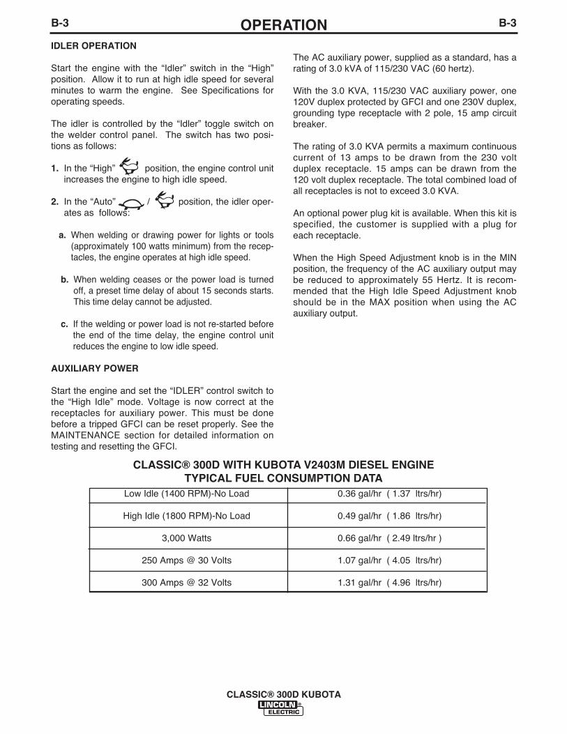
CLASSIC® 300D WITH KUBOTA V2403M DIESEL ENGINETYPICAL FUEL CONSUMPTION DATA
Low Idle (1400 RPM)-No Load
High Idle (1800 RPM)-No Load
3,000 Watts
250 Amps @ 30 Volts
300 Amps @ 32 Volts
0.36 gal/hr ( 1.37 ltrs/hr)
0.49 gal/hr ( 1.86 ltrs/hr)
0.66 gal/hr ( 2.49 ltrs/hr )
1.07 gal/hr ( 4.05 ltrs/hr)
1.31 gal/hr ( 4.96 ltrs/hr)
The AC auxiliary power, supplied as a standard, has arating of 3.0 kVA of 115/230 VAC (60 hertz).
With the 3.0 KVA, 115/230 VAC auxiliary power, one120V duplex protected by GFCI and one 230V duplex,grounding type receptacle with 2 pole, 15 amp circuitbreaker.
The rating of 3.0 KVA permits a maximum continuouscurrent of 13 amps to be drawn from the 230 voltduplex receptacle. 15 amps can be drawn from the120 volt duplex receptacle. The total combined load ofall receptacles is not to exceed 3.0 KVA.
An optional power plug kit is available. When this kit isspecified, the customer is supplied with a plug foreach receptacle.
When the High Speed Adjustment knob is in the MINposition, the frequency of the AC auxiliary output maybe reduced to approximately 55 Hertz. It is recom-mended that the High Idle Speed Adjustment knobshould be in the MAX position when using the ACauxiliary output.
C-1ACCESSORIESC-1
CLASSIC® 300D KUBOTA
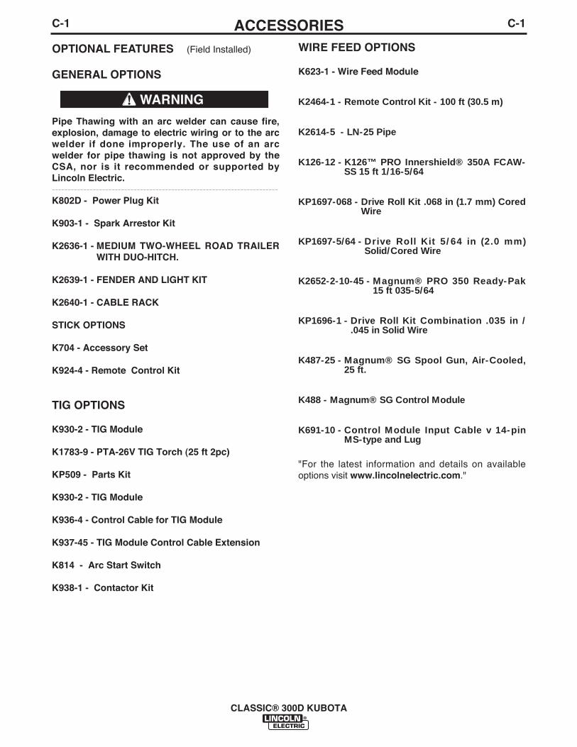
OPTIONAL FEATURES (Field Installed)
GENERAL OPTIONS
Pipe Thawing with an arc welder can cause fire,explosion, damage to electric wiring or to the arcwelder if done improperly. The use of an arcwelder for pipe thawing is not approved by theCSA, nor is it recommended or supported byLincoln Electric.------------------------------------------------------------------------K802D - Power Plug Kit
K903-1 - Spark Arrestor Kit
K2636-1 - MEDIUM TWO-WHEEL ROAD TRAILERWITH DUO-HITCH.
K2639-1 - FENDER AND LIGHT KIT
K2640-1 - CABLE RACK
STICK OPTIONS
K704 - Accessory Set
K924-4 - Remote Control Kit
TIG OPTIONS
K930-2 - TIG Module
K1783-9 - PTA-26V TIG Torch (25 ft 2pc)
KP509 - Parts Kit
K930-2 - TIG Module
K936-4 - Control Cable for TIG Module
K937-45 - TIG Module Control Cable Extension
K814 - Arc Start Switch
K938-1 - Contactor Kit
WIRE FEED OPTIONS
K623-1 - Wire Feed Module
K2464-1 - Remote Control Kit - 100 ft (30.5 m)
K2614-5 - LN-25 Pipe
K126-12 - K126™ PRO Innershield® 350A FCAW-SS 15 ft 1/16-5/64
KP1697-068 - Drive Roll Kit .068 in (1.7 mm) CoredWire
KP1697-5/64 - Drive Roll Kit 5/64 in (2.0 mm)Solid/Cored Wire
K2652-2-10-45 - Magnum® PRO 350 Ready-Pak15 ft 035-5/64
KP1696-1 - Drive Roll Kit Combination .035 in /.045 in Solid Wire
K487-25 - Magnum® SG Spool Gun, Air-Cooled,25 ft.
K488 - Magnum® SG Control Module
K691-10 - Control Module Input Cable v 14-pinMS-type and Lug
"For the latest information and details on availableoptions visit www.lincolnelectric.com."
WARNING
D-1MAINTENANCED-1
MAINTENANCE
GENERAL INSTRUCTIONS
1. Blow out the welder and controls with an air hose atleast once every two months. In particularly dirtylocations, this cleaning may be necessary once aweek. Use low pressure air to avoid driving dirt intothe insulation.
2. “Current Range Selector” contacts should not begreased. To keep the contacts clean, rotate the cur-rent control through its entire range frequently.Good practice is to turn the handle from maximumto minimum setting twice each morning before start-ing to weld.
3. Put a drop of oil on the “Current Range Selector”shaft at least once every month.
4. Follow the engine service schedule in this manualand the detailed maintenance and troubleshooting inthe engine manufacturerʼs manual.
COOLING SYSTEM
The CLASSIC® 300D KUBOTA is equipped with apressure radiator. Keep the radiator cap tight to pre-vent loss of coolant. Clean and flush the cooling sys-tem periodically to prevent clogging the passage andoverheating the engine. When antifreeze is needed,always use the permanent type.
BEARINGS(For Codes 11547, 11548, 11642, 11643)This welder is equipped with a double-shielded ballbearing having sufficient grease to last indefinitelyunder normal service. Where the welder is used con-stantly or in excessively dirty locations, it may be nec-essary to add one half ounce of grease per year. Apad of grease one inch wide, one inch long, and oneinch high weighs approximately one half ounce. Over-greasing is far worse than insufficient greasing.
When greasing the bearings, keep all dirt out of thearea. Wipe the fittings completely clean and use cleanequipment. More bearing failures are caused by dirtintroduced during greasing than from insufficientgrease.
(For Codes 11811, 11812)This welder is equipped with a double syntheticsealed ball bearing having sufficient grease to lastindefinitely under normal service.
COMMUTATOR AND BRUSHES
Uncovered rotating equipment can be dangerous.Use care so your hands, hair, clothing or tools donot catch in the rotating parts. Protect yourselffrom particles that may be thrown out by the rotat-ing armature when stoning the commutator.------------------------------------------------------------------------Shifting of the commutator brushes may result in:
- Change in machine output- Commutator damage- Excessive brush wear
Periodically inspect the commutator, slip rings, andbrushes by removing the covers. DO NOT remove orreplace these covers while the machine is running.Commutators and slip rings require little attention.However, if they are black or appear uneven, havethem cleaned by an experienced maintenance man using fine sandpaper or a commutator stone. Neveruse emery cloth or paper for this purpose.
CLASSIC® 300D KUBOTA
Have qualified personnel do the maintenancework. Turn the engine off before working insidethe machine. In some cases, it may be neces-sary to remove safety guards to performrequired maintenance. Remove guards onlywhen necessary and replace them when themaintenance requiring their removal is com-plete. Always use the greatest care when work-ing near moving parts.
Do not put your hands near the engine coolingblower fan. If a problem cannot be corrected byfollowing the instructions, take the machine tothe nearest Lincoln Field Service Shop.
-----------------------------------------------------------------------ELECTRIC SHOCK can kill.• Do not touch electrically live parts or
electrode with skin or wet clothing.• Insulate yourself from work and
ground• Always wear dry insulating gloves.
------------------------------------------------------------------------ENGINE EXHAUST can kill.• Use in open, well ventilated areas or
vent exhaust outside.
------------------------------------------------------------------------MOVING PARTS can injure.• Do not operate with doors open or
guards off.• Stop engine before servicing.• Keep away from moving parts.
------------------------------------------------------------------------See additional warning information atfront of this operatorʼs manual.
-----------------------------------------------------------
WARNING
WARNING

D-2MAINTENANCED-2
Replace brushes when they wear within 1/4”(3.5mm)of the pigtail. A complete set of replacement brushesshould be kept on hand. Lincoln brushes have acurved face to fit the commutator. Have an experi-enced maintenance man seat these brushes by lightlystoning the commutator as the armature rotates at fullspeed until contact is made across the full face of thebrushes. After stoning, blow out the dust with lowpressure air.
To seat slip ring brushes, position the brushes inplace. Then slide one end of a piece of fine sandpaperbetween slip rings and brushes with the coarse sideagainst the brushes. With slight additional finger pres-sure on top of the brushes, pull the sandpaper aroundthe circumference of the rings - in direction of rotationonly - until brushes seat properly. In addition, stoneslip ring with a fine stone. Brushes must be seated100%.
Arcing or excessive exciter brush wear indicates apossible misaligned shaft. Have an authorized FieldService Shop check and realign the shaft.
IDLER MAINTENANCEBefore doing electrical work, disconnect the bat-tery.------------------------------------------------------------------------When installing a new battery or using a jumper bat-tery to start the engine, be sure the battery polarity isconnected properly. The correct polarity is negativeground. Damage to the engine alternator and theEngine Control Unit can result from incorrect connec-tion.
1. Proper operation of the idler requires goodgrounding of the Engine Control Unit, currentsensing printed circuit board and battery.
2. If desired, the welder can be used without automat-ic idling by setting the “Idler” switch to the “High”position.
NAMEPLATES
Whenever routine maintenance is performed on thismachine - or at least yearly - inspect all nameplatesand labels for legibility. Replace those which are nolonger clear. Refer to the parts list for the replace-ment item number.
PURGING AIR FROM FUEL SYSTEM(KUBOTA V2403M ENGINE)
Keep fuel clear of open flames or arcs, allowengine to cool before working on the fuel system.Wipe up any spilled fuel and do not start engineuntil fumes clear.------------------------------------------------------------------------If the engine is running rough and you suspect air hasbeen trapped in the fuel system, (e.g. the engine wasallowed to run out of fuel) perform the following stepsusing qualified personnel:
1. Fully open the air bleeding valve by turning itcounter clockwise, it is located on top of the fuelinjection pump next to the oil filler. (see figure D.1)
FIGURE D.1
2. Turn the engine by pressing the start button untilthe engine runs smoothly (this should take approxi-mately 10 seconds).
3. Fully close the air bleeding valve by turning itclockwise.
Contact your Kubota Engine repair facility if problemspersist.
CLASSIC® 300D KUBOTA
CAUTION
WARNING
Air Bleeding Valve
D-3D-3
CLASSIC® 300D KUBOTA
MAINTENANCE
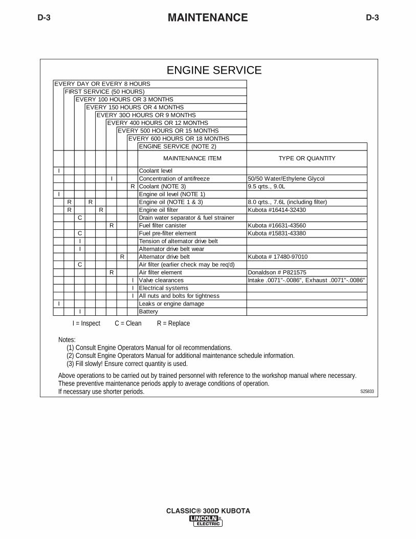
If necessary use shorter periods.These preventive maintenance periods apply to average conditions of operation.Above operations to be carried out by trained personnel with reference to the workshop manual where necessary.
(3) Fill slowly! Ensure correct quantity is used.(2) Consult Engine Operators Manual for additional maintenance schedule information.(1) Consult Engine Operators Manual for oil recommendations.
Notes:
ENGINE SERVICE
S25833
R = ReplaceC = CleanI = Inspect
EVERY DAY OR EVERY 8 HOURSFIRST SERVICE (50 HOURS)
EVERY 100 HOURS OR 3 MONTHSEVERY 150 HOURS OR 4 MONTHS
EVERY 30O HOURS OR 9 MONTHSEVERY 400 HOURS OR 12 MONTHS
EVERY 500 HOURS OR 15 MONTHSEVERY 600 HOURS OR 18 MONTHS
ENGINE SERVICE (NOTE 2)
TYPE OR QUANTITY
II 50/50 Water/Ethylene Glycol
R 9.5 qrts., 9.0LI
R R 8.0 qrts., 7.6L (including filter)R R Kubota #16414-32430
CR Kubota #16631-43560
C Kubota #15831-43380II
R Kubota # 17480-97010C
R Donaldson # P821575I Intake .0071"-.0086", Exhaust .0071"-.0086"II
II
MAINTENANCE ITEM
Coolant (NOTE 3)
Fuel filter canister
Coolant levelConcentration of antifreeze
Tension of alternator drive belt
Engine oil level (NOTE 1)Engine oil (NOTE 1 & 3)Engine oil filterDrain water separator & fuel strainer
Fuel pre-filter element
Leaks or engine damageBattery
Valve clearancesElectrical systemsAll nuts and bolts for tightness
Alternator drive belt wearAlternator drive beltAir filter (earlier check may be req'd)Air filter element
D-4MAINTENANCED-4
GFCI TESTING AND RESETTINGPROCEDURE
The GFCI should be properly tested at least onceevery month or whenever it is tripped. To properly testand reset the GFCI :
• If the GFCI has tripped, first carefully remove anyload and check it for damage.
• If the equipment has been shut down, it must berestarted.
• The equipment needs to be operating at high idlespeed and any necessary adjustments made on thecontrol panel so that the equipment is providing atleast 80 volts to the receptacle input terminals.
• The circuit breaker for this receptacle must not betripped. Reset if necessary.
• Push the "Reset" button located on the GFCI. Thiswill assure normal GFCI operation.
• Plug a night-light (with an "ON/OFF" switch) or otherproduct (such as a lamp) into the Duplex receptacleand turn the product "ON".
• Push the "Test" button located on the GFCI. Thenight-light or other product should go "OFF".
• Push the "Reset" button, again. The light or otherproduct should go "ON" again.
If the light or other product remains "ON" when the"Test" button is pushed, the GFCI is not working prop-erly or has been incorrectly installed (miswired). Ifyour GFCI is not working properly, contact a qualified,certified electrician who can assess the situation,rewire the GFCI if necessary or replace the device.
CLASSIC® 300D KUBOTA
E-1TROUBLESHOOTING
CLASSIC® 300D KUBOTA
E-1
If for any reason you do not understand the test procedures or are unable to perform the tests/repairs safely, contact yourLocal Lincoln Authorized Field Service Facility for technical troubleshooting assistance before you proceed.
CAUTION
This Troubleshooting Guide is provided to help youlocate and repair possible machine malfunctions.Simply follow the three-step procedure listed below.
Step 1. LOCATE PROBLEM (SYMPTOM).Look under the column labeled “PROBLEM (SYMP-TOMS)”. This column describes possible symptomsthat the machine may exhibit. Find the listing thatbest describes the symptom that the machine isexhibiting.
Step 2. POSSIBLE CAUSE.The second column labeled “POSSIBLE CAUSE” liststhe obvious external possibilities that may contributeto the machine symptom.
Step 3. RECOMMENDED COURSE OF ACTIONThis column provides a course of action for thePossible Cause, generally it states to contact yourlocal Lincoln Authorized Field Service Facility.
If you do not understand or are unable to perform theRecommended Course of Action safely, contact yourlocal Lincoln Authorized Field Service Facility.
HOW TO USE TROUBLESHOOTING GUIDE
Service and Repair should only be performed by Lincoln Electric Factory Trained Personnel.Unauthorized repairs performed on this equipment may result in danger to the technician andmachine operator and will invalidate your factory warranty. For your safety and to avoid ElectricalShock, please observe all safety notes and precautions detailed throughout this manual.
__________________________________________________________________________
WARNING
E-2TROUBLESHOOTINGE-2
CLASSIC® 300D KUBOTA
Observe all Safety Guidelines detailed throughout this manual
If for any reason you do not understand the test procedures or are unable to perform the tests/repairs safely, contact yourLocal Lincoln Authorized Field Service Facility for technical troubleshooting assistance before you proceed.
CAUTION
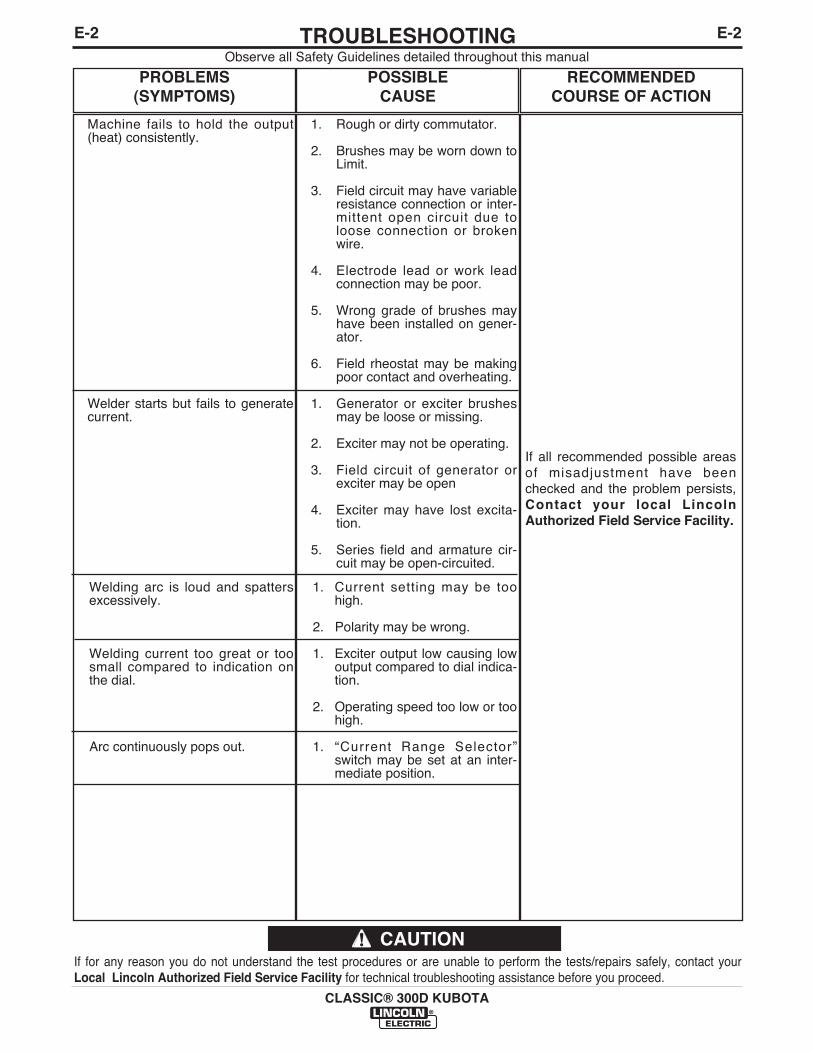
PROBLEMS(SYMPTOMS)
POSSIBLE CAUSE
RECOMMENDEDCOURSE OF ACTION
Machine fails to hold the output(heat) consistently.
Welder starts but fails to generatecurrent.
Welding arc is loud and spattersexcessively.
Welding current too great or toosmall compared to indication onthe dial.
Arc continuously pops out.
1. Rough or dirty commutator.
2. Brushes may be worn down toLimit.
3. Field circuit may have variableresistance connection or inter-mittent open circuit due toloose connection or brokenwire.
4. Electrode lead or work leadconnection may be poor.
5. Wrong grade of brushes mayhave been installed on gener-ator.
6. Field rheostat may be makingpoor contact and overheating.
1. Generator or exciter brushesmay be loose or missing.
2. Exciter may not be operating.
3. Field circuit of generator orexciter may be open
4. Exciter may have lost excita-tion.
5. Series field and armature cir-cuit may be open-circuited.
1. Current setting may be toohigh.
2. Polarity may be wrong.
1. Exciter output low causing lowoutput compared to dial indica-tion.
2. Operating speed too low or toohigh.
1. “Current Range Selector”switch may be set at an inter-mediate position.
If all recommended possible areasof misadjustment have beenchecked and the problem persists,Contact your local LincolnAuthorized Field Service Facility.

E-3TROUBLESHOOTING
CLASSIC® 300D KUBOTA
E-3
ELECTRONIC IDLER TROUBLESHOOTING GUIDE
With Idler Control Switch in the Auto Position,Engine Will Not Return to Low Idle in Approximately 15 Seconds
After Welding and Auxiliary Loads are Removed
Set Idler Control Switchto the Auto Position
Check for Continuity through IdlerControl Switch
Open Closed
Check Voltage across Replace IdlerIdler Control switch Control Switch
12 VDC 0 VDC
Contact Kubota Replace currentEngine Repair Sensing PCBFacility
If for any reason you do not understand the test procedures or are unable to perform the tests/repairs safely, contact yourLocal Lincoln Authorized Field Service Facility for technical troubleshooting assistance before you proceed.
CAUTION

With Idler Control Switch in the AUTO Position, Engine Will Not Pick Up Speed When:
The Arc is Struck Both Auxiliary Load
1. Check Idler circuit wiring. PossibleProblems are wires from Current SensingBoard reversed at idler switch or wiresconnected incorrectly at Current SensorMolex plug.
2. Check voltage across idler controlswitch.
12V 0V
Replace Current Contact Kubota Sensing PCB Engine Repair
Facility.
E-4TROUBLESHOOTING
CLASSIC® 300D KUBOTA
E-4
ELECTRONIC IDLER CONTROL TROUBLESHOOTING GUIDE
If for any reason you do not understand the test procedures or are unable to perform the tests/repairs safely, contact yourLocal Lincoln Authorized Field Service Facility for technical troubleshooting assistance before you proceed.
CAUTION
Check for loose or disconnectedwire running between weld
selector switch and output stud.
1. Load too small. Try loadabove 100 Watts.
2. Check for loose or discon-nected wire running fromblack lead out of exciter toCB2 circuit breaker.

E-5TROUBLESHOOTINGE-5
CLASSIC® 300D KUBOTA
Observe all Safety Guidelines detailed throughout this manual
If for any reason you do not understand the test procedures or are unable to perform the tests/repairs safely, contact yourLocal Lincoln Authorized Field Service Facility for technical troubleshooting assistance before you proceed.
CAUTION
PROBLEMS(SYMPTOMS)
POSSIBLE CAUSE
RECOMMENDEDCOURSE OF ACTION
Engine does not start.
Engine does not turn over.
Irregular running of the engine.
Engine stops during operation andthe Engine Protection light doesnot turn on.
Engine stops during operation andthe Engine Protection light doesturn on.
1. Lack of fuel.
2. Air mixed in the fuel system.
3. Clogged fuel filter.
4. Irregular and faulty fuel supply(Injector pump trouble).
5. Glow plug not heated.
6. Clogged air cleaner.
7. No compression.
8. Engine protection light is ON.
1. Faulty Ignition switch and orInjector pump solenoid.
2. Insufficient charging or com-plete discharge of the battery.
3. Improper viscosity of the lubri-cating oil.
1. Air mixed in the fuel system.
2. Uneven fuel injection (Faultyfuel injector pump).
3. Clogged fuel filter.
4. Defective governor.
5. Engine itself defective.
1. Lack of fuel in the fuel tank.
2. Clogged fuel filter.
3. Air mixed in the fuel system.
4. Faulty function of the engine.
See Light Code DiagnosesAttached.
If all recommended possible areasof misadjustment have beenchecked and the problem persists,Contact your local LincolnAuthorized Field Service Facility.

E-6TROUBLESHOOTINGE-6
CLASSIC® 300D KUBOTA
Observe all Safety Guidelines detailed throughout this manual
If for any reason you do not understand the test procedures or are unable to perform the tests/repairs safely, contact yourLocal Lincoln Authorized Field Service Facility for technical troubleshooting assistance before you proceed.
CAUTION
LIGHT CODE FAILURE DETECTED POSSIBLE CAUSE - CORRECTIVE MEASURE
LONG 1, SHORT 1 RPM IS OVER 115% OF RATED RPM (2070 RPM) ACTUATOR IS STUCK - REMOVE ACTUATOR AND VERIFYPLUNGER PULLS IN WHEN ENERGIZED
LONG 1, SHORT 2 LOW OIL PRESSURE DETECTED FOR 1 SECOND LOW OIL - CHECK OIL LEVEL ON DIPSTICKFAULTY OIL PRESSURE SWITCH - CHECK THAT "WK"STUD IS OPEN WHEN ENGINE IS RUNNINGLEAD TO OIL PRESSURE SWITCH "WK" STUD MAY BEGROUNDED - CHECK
LONG 1, SHORT 3 "L" TERMINAL IS GROUNDED ON ALTERNATOR BROKEN OR LOOSE BELTFOR 1 SECOND LEAD TO "L" TERMINAL ON ALTERNATOR MAYBE
SHORTED TO GROUND- CHECKFAULTY ALTERNATOR - CHECK
LONG 1, SHORT 4 HIGH WATER TEMPERATURE DETECTED AMOUNT OR QUALITY OF COOLANT INCORRECTFOR 1 SECOND - CHECK
FAULTY WATER TEMPERATURE SWITCH - CHECK THAT"WK" STUD IS OPEN WHEN ENGINE IS NOT RUNNINGLEAD TO WATER TEMPERATURE SWITCH MAY BE GROUNDED - CHECK
LONG 1, SHORT 5 NOT ENABLED FOR LINCOLN PRODUCTS
LONG 2, SHORT 1 0 RPM IS DETECTED AND 12V IS DETECTED FAULTY RPM SENSOR-CHECK FOR GOOD CONNECTIONFROM "L" TERMINAL ON ALTERNATOR FAULTY ECU - CHECK FOR 12 VOLTS ON SUPPLY LEAD
TO RPM SENSOR FROM ECU LONG 2, SHORT 2 CURRENT TO ACTUATOR IS OUT OF LIMIT FAULTY ACTUATOR - CHECK FOR PROPER COIL
RESISTANCE LEADS TO ACTUATOR MAY BE OPEN OR GROUNDED- CHECK
LONG 2, SHORT 3 NOT ENABLED FOR LINCOLN PRODUCTS
LONG 2, SHORT 4 -50C WATER TEMPERATURE DETECTED FAULTY WATER TEMPERATURE SENSOR - CHECK FORPROPER RESISTANCELEAD TO WATER TEMPERATURE SENSOR MAY BE OPEN- CHECK FOR CONTINUITY
LONG 2, SHORT 5 150C WATER TEMPERATURE DETECTED FAULTY WATER TEMPERATURE SENSOR - CHECK FOR PROPER RESISTANCELEAD TO WATER TEMPERATURE SENSOR MAY BE GROUNDED - CHECK
LONG 2, SHORT 6 0 VOLTS DETECTED FROM "L" TERMINAL ON LEAD TO "L" TERMINAL ON ALTERNATOR MAY BE OPEN ALTERNATOR FOR 1 SECOND - CHECK FOR CONTINUITY
BROKEN OR LOOSE BELT - INSPECTFAULTY ALTERNATOR - CHECK
LONG 2, SHORT 7 OVER 18 VOLTS DETECTED FROM ALTERNATOR INCORRECT BATTERY - INSPECTFAULTY ALTERNATOR - CHECK
LONG 2, SHORT 8 LESS THAN 4 VOLTS TO RPM SENSOR AND/OR FAULTY ECU -CHECK FOR 12 VOLTS ON LEADS TO RPMACTUATOR SENSED BY ECU SENSOR AND ACTUATOR FROM ECU
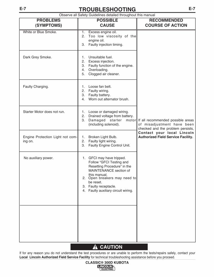
E-7TROUBLESHOOTINGE-7
CLASSIC® 300D KUBOTA
Observe all Safety Guidelines detailed throughout this manual
If for any reason you do not understand the test procedures or are unable to perform the tests/repairs safely, contact yourLocal Lincoln Authorized Field Service Facility for technical troubleshooting assistance before you proceed.
CAUTION
PROBLEMS(SYMPTOMS)
POSSIBLE CAUSE
RECOMMENDEDCOURSE OF ACTION
White or Blue Smoke.
Dark Grey Smoke.
Faulty Charging.
Starter Motor does not run.
Engine Protection Light not com-ing on.
No auxiliary power.
1. Excess engine oil.2. Too low viscosity of the
engine oil.3. Faulty injection timing.
1. Unsuitable fuel.2. Excess injection.3. Faulty function of the engine.4. Overloading.5. Clogged air cleaner.
1. Loose fan belt.2. Faulty wiring.3. Faulty battery.4. Worn out alternator brush.
1. Loose or damaged wiring.2. Drained voltage from battery.3. Damaged starter motor
(including solenoid).
1. Broken Light Bulb.2. Faulty light wiring. 3. Faulty Engine Control Unit.
1. GFCI may have tripped.Follow “GFCI Testing andResetting Procedure” in theMAINTENANCE section ofthis manual.
2. Open breakers may need tobe reset.
3. Faulty receptacle. 4. Faulty auxiliary circuit wiring.
If all recommended possible areasof misadjustment have beenchecked and the problem persists,Contact your local LincolnAuthorized Field Service Facility.
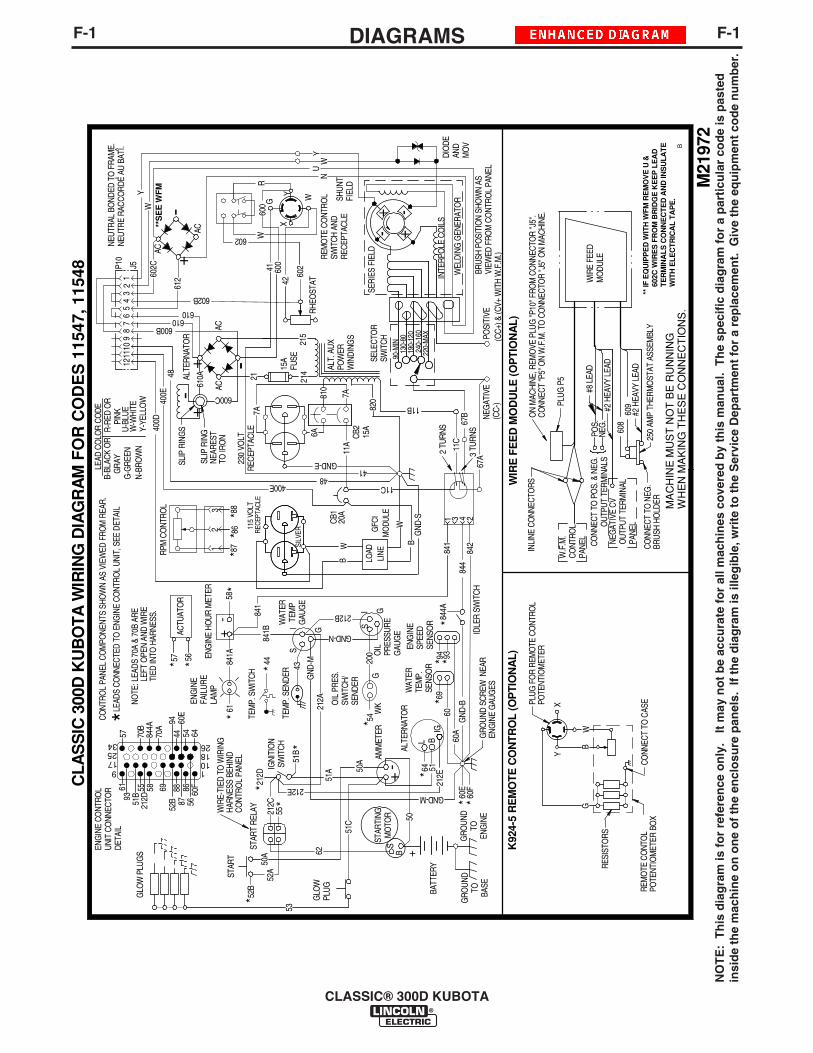
CLASSIC® 300D KUBOTA
F-1DIAGRAMSF-1
NO
TE
: T
his
dia
gra
m is
fo
r re
fere
nce
on
ly.
It m
ay n
ot
be
accu
rate
fo
r al
l mac
hin
es c
ove
red
by
this
man
ual
. T
he
spec
ific
dia
gra
m f
or
a p
arti
cula
r co
de
is p
aste
din
sid
e th
e m
ach
ine
on
on
e o
f th
e en
clo
sure
pan
els.
If
the
dia
gra
m is
ille
gib
le, w
rite
to
th
e S
ervi
ce D
epar
tmen
t fo
r a
rep
lace
men
t. G
ive
the
equ
ipm
ent
cod
e n
um
ber
.
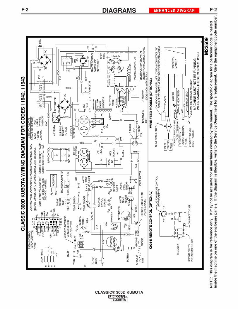
F-2DIAGRAMSF-2
CLASSIC® 300D KUBOTA
NO
TE
: T
his
dia
gra
m is
fo
r re
fere
nce
on
ly.
It m
ay n
ot
be
accu
rate
fo
r al
l mac
hin
es c
ove
red
by
this
man
ual
. T
he
spec
ific
dia
gra
m f
or
a p
arti
cula
r co
de
is p
aste
din
sid
e th
e m
ach
ine
on
on
e o
f th
e en
clo
sure
pan
els.
If
the
dia
gra
m is
ille
gib
le, w
rite
to
th
e S
ervi
ce D
epar
tmen
t fo
r a
rep
lace
men
t. G
ive
the
equ
ipm
ent
cod
e n
um
ber
.
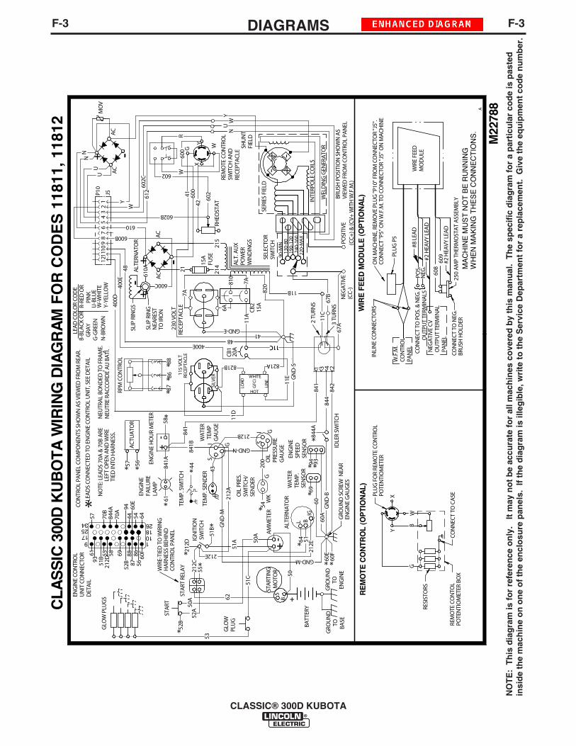
F-3DIAGRAMSF-3
CLASSIC® 300D KUBOTA
NO
TE
: T
his
dia
gra
m is
fo
r re
fere
nce
on
ly.
It m
ay n
ot
be
accu
rate
fo
r al
l mac
hin
es c
ove
red
by
this
man
ual
. T
he
spec
ific
dia
gra
m f
or
a p
arti
cula
r co
de
is p
aste
din
sid
e th
e m
ach
ine
on
on
e o
f th
e en
clo
sure
pan
els.
If
the
dia
gra
m is
ille
gib
le, w
rite
to
th
e S
ervi
ce D
epar
tmen
t fo
r a
rep
lace
men
t. G
ive
the
equ
ipm
ent
cod
e n
um
ber
.
M22
788
SB
WIR
E F
EE
D M
OD
ULE
(OP
TIO
NA
L)
608
609
+
CLA
SS
IC 3
00D
KU
BO
TA W
IRIN
G D
IAG
RA
M F
OR
CO
DE
S 1
1811
, 118
12
NEG
ATI
VE(C
C-)
67B
A
PLU
G P
5
INLI
NE
CON
NEC
TORS
W.F
.M.
CON
TRO
LPA
NEL CO
NN
ECT
TO P
OS.
& N
EG.
OU
TPU
T TE
RMIN
ALS
POS.
NEG
.
#8 L
EAD
#2 H
EAVY
LEA
D
#2 H
EAVY
LEA
D
NEG
ATI
VE C
VO
UTP
UT
TERM
INA
LPA
NEL
CON
NEC
T TO
NEG
.BR
USH
HO
LDER
250
AM
P TH
ERM
OST
AT
ASS
EMBL
Y
MA
CH
INE
MU
ST
NO
T B
E R
UN
NIN
GW
HE
N M
AK
ING
TH
ES
E C
ON
NE
CT
ION
S.
64
62
GRO
UN
DTO BA
SE
GRO
UN
DTO
ENG
INE21
2C
GN
D-B
60A GRO
UN
D S
CREW
NEA
REN
GIN
E G
AU
GES
60
SI G
212A
841B
WA
TER
TEM
PG
AU
GE
GND-N
GND-M
POSI
TIVE
(CC+
) & (C
V+ W
ITH
W.F
.M.)
51C
GLO
WPL
UG
53
52A
52B
STA
RT61
ENG
INE
FAIL
URE
LAM
P
841A
STA
RT R
ELA
Y
55IG
NIT
ION
SWIT
CH
51A
51B
212D
ENG
INE
HO
UR
MET
ER
-+
58
841
SI G
OIL
PRES
SURE
GA
UG
E
212B
50A -
+A
MM
ETER IG
BL51
212E
ALT
ERN
ATO
R
94
ENG
INE
SPEE
DSE
NSO
R
93
WA
TER
TEM
P.SE
NSO
R44
TEM
P. S
END
ER43
54W
KG
200
OIL
PRE
S.SW
ITCH
/SE
ND
ER
1 3 4 2
11B
STA
RTIN
GM
OTO
R
41
610
600B
602B34
56
78
910
1112
48
400D
400E
21ALT
ERN
ATO
R
600C
+-
SLIP
RIN
GS
SLIP
RIN
GN
EARE
STTO
IRO
N
7A
GND-E230
VOLT
RECE
PTA
CLE
610A
+ -
215
AC
AC
15A
FUSE
214 A
LT. A
UX
POW
ERW
IND
ING
S
820
J5P10
12 42
60241
600
602
600
RHEO
STA
T
R
YX
WGW W
IRE
FEED
MO
DU
LE
GLO
W P
LUG
S
PLU
G F
OR
REM
OTE
CO
NTR
OL
POTE
NTI
OM
ETER
CON
NEC
T TO
CA
SERE
MO
TE C
ON
TOL
POTE
NTI
OM
ETER
BO
X
RESI
STO
RS
RE
MO
TE C
ON
TRO
L (O
PTI
ON
AL)
YX
BG
W
NU
YW
--
++
INTE
RPO
LE C
OIL
S
SHU
NT
FIEL
D
SERI
ES F
IELD
BRU
SH P
OSI
TIO
N S
HO
WN
AS
VIEW
ED F
ROM
CO
NTR
OL
PAN
EL
SELE
CTO
RSW
ITCH
90-M
IN13
0-80
190-
120
240-
160
220-
MAX
WEL
DIN
G G
ENER
ATO
R
* *
**
*
*
*
*
*
* *
**
*
***
*
RPM
CO
NTR
OL
12
3
8688
87
*LEA
DS
CON
NEC
TED
TO
EN
GIN
E CO
NTR
OL
UN
IT, S
EE D
ETA
IL
'N
EUTR
AL
BON
DED
TO
FRA
ME.
NEU
TRE
RACC
ORD
E A
U B
ATI
.
CON
TRO
L PA
NEL
CO
MPO
NEN
TS S
HO
WN
AS
VIEW
ED F
ROM
REA
R.LE
AD
CO
LOR
COD
E
G-G
REEN
N-B
ROW
N
U-B
LUE
W-W
HIT
EY-
YELL
OW
B-BL
ACK
OR
G
RAY
R-RE
D O
R
PIN
K
5657A
CTU
ATO
R
844A
IDLE
R SW
ITCH
*84
460
E60
F
ENG
INE
CON
TRO
LU
NIT
CO
NN
ECTO
RD
ETA
IL
REM
OTE
CO
NTR
OL
SWIT
CH A
ND
RECE
PTA
CLE
MO
V
BATT
ERY
69 *NO
TE: L
EAD
S 70
A &
70B
ARE
LEFT
OPE
N A
ND
WIR
E
TI
ED IN
TO H
ARN
ESS.
841
ON
MA
CHIN
E, R
EMO
VE P
LUG
"P10
" FRO
M C
ON
NEC
TOR
"J5"
.CO
NN
ECT
"P5"
ON
W.F
.M. T
O C
ON
NEC
TOR
"J5"
ON
MA
CHIN
E.
50
WIR
E-TI
ED T
O W
IRIN
GH
ARN
ESS
BEH
IND
CON
TRO
L PA
NEL
18
8855
568793
52B
60F8658 69
51B
61
60E
44
212D
6454
94
70A
844A
70B
57
110
263425179
2 TU
RNS
3 TU
RNS
67A
11C
20A
CB1
11C48
400E
CB2
15A
7A
6A81
0
11A
842
50A
GN
D-M
212ETE
MP.
SW
ITCH
RECE
PTA
CLE
SILV
ER
115
VOLT
+
AC
-
-
GN
D-S
AC
Y
N
UU
N
W
602C
612
LINE
LOAD
GFC
I
HOT
WHITE821A
11C
821B
11D
11E
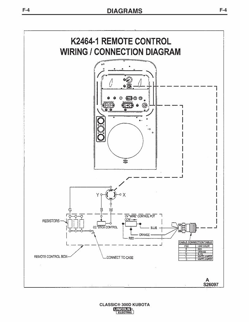
F-4DIAGRAMSF-4
CLASSIC® 300D KUBOTA
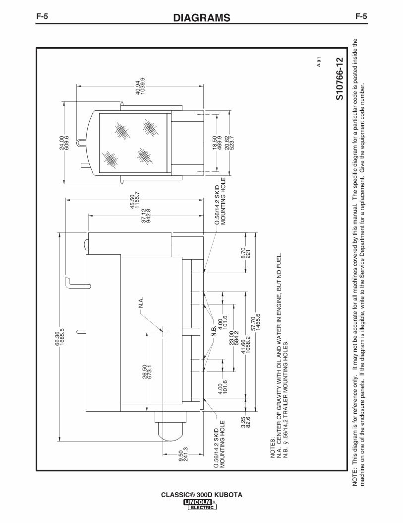
F-5DIAGRAMSF-5
CLASSIC® 300D KUBOTA
NO
TE
: T
his
diag
ram
is fo
r re
fere
nce
only
. It
may
not
be
accu
rate
for
all m
achi
nes
cove
red
by th
is m
anua
l. T
he s
peci
fic d
iagr
am fo
r a
part
icul
ar c
ode
is p
aste
d in
side
the
mac
hine
on
one
of th
e en
clos
ure
pane
ls.
If th
e di
agra
m is
ille
gibl
e, w
rite
to th
e S
ervi
ce D
epar
tmen
t for
a r
epla
cem
ent.
Giv
e th
e eq
uipm
ent c
ode
num
ber.
S10
766-
12 A. 0
1
24.0
060
9.6
37.1
294
2.8
66.3
616
85.5
4.00
101.
64.
0010
1.6
23.0
058
4.2
8.70
221
41.6
610
58.2
3.25
82.6
57.7
014
65.6
O.5
6/14
.2 S
KID
MO
UN
TIN
G H
OLE
O.5
6/14
.2 S
KID
MO
UN
TIN
G H
OLE
N.B
.N
.B.
N.A
.
NO
TE
S:
N.A
. C
EN
TE
R O
F G
RA
VIT
Y W
ITH
OIL
AN
D W
AT
ER
IN E
NG
INE
, BU
T N
O F
UE
L. N
.B.
ÿ.5
6/14
.2 T
RA
ILE
R M
OU
NT
ING
HO
LES
.
20.6
252
3.7
18.5
046
9.9
40.9
410
39.9
45.5
011
55.7
26.5
067
3.1
9.50
241.
3

NOTES
CLASSIC® 300D KUBOTA
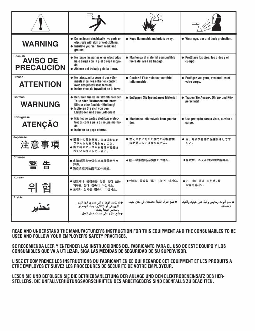
WARNING
AVISO DEPRECAUCION
ATTENTION
WARNUNG
ATENÇÃO
Spanish
French
German
Portuguese
Japanese
Chinese
Korean
Arabic
READ AND UNDERSTAND THE MANUFACTURER’S INSTRUCTION FOR THIS EQUIPMENT AND THE CONSUMABLES TO BEUSED AND FOLLOW YOUR EMPLOYER’S SAFETY PRACTICES.
SE RECOMIENDA LEER Y ENTENDER LAS INSTRUCCIONES DEL FABRICANTE PARA EL USO DE ESTE EQUIPO Y LOSCONSUMIBLES QUE VA A UTILIZAR, SIGA LAS MEDIDAS DE SEGURIDAD DE SU SUPERVISOR.
LISEZ ET COMPRENEZ LES INSTRUCTIONS DU FABRICANT EN CE QUI REGARDE CET EQUIPMENT ET LES PRODUITS AETRE EMPLOYES ET SUIVEZ LES PROCEDURES DE SECURITE DE VOTRE EMPLOYEUR.
LESEN SIE UND BEFOLGEN SIE DIE BETRIEBSANLEITUNG DER ANLAGE UND DEN ELEKTRODENEINSATZ DES HER-STELLERS. DIE UNFALLVERHÜTUNGSVORSCHRIFTEN DES ARBEITGEBERS SIND EBENFALLS ZU BEACHTEN.
Do not touch electrically live parts orelectrode with skin or wet clothing.Insulate yourself from work andground.
No toque las partes o los electrodosbajo carga con la piel o ropa moja-da.Aislese del trabajo y de la tierra.
Ne laissez ni la peau ni des vête-ments mouillés entrer en contactavec des pièces sous tension.Isolez-vous du travail et de la terre.
Berühren Sie keine stromführendenTeile oder Elektroden mit IhremKörper oder feuchter Kleidung!Isolieren Sie sich von denElektroden und dem Erdboden!
Não toque partes elétricas e elec-trodos com a pele ou roupa molha-da.Isole-se da peça e terra.
Keep flammable materials away.
Mantenga el material combustiblefuera del área de trabajo.
Gardez à l’écart de tout matérielinflammable.
Entfernen Sie brennbarres Material!
Mantenha inflamáveis bem guarda-dos.
Wear eye, ear and body protection.
Protéjase los ojos, los oídos y elcuerpo.
Protégez vos yeux, vos oreilles etvotre corps.
Tragen Sie Augen-, Ohren- und Kör-perschutz!
Use proteção para a vista, ouvido ecorpo.
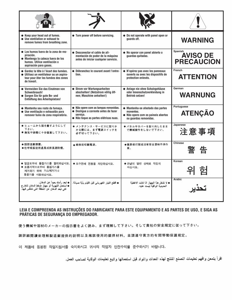
WARNING
AVISO DEPRECAUCION
ATTENTION
WARNUNG
ATENÇÃO
Spanish
French
German
Portuguese
Japanese
Chinese
Korean
Arabic
LEIA E COMPREENDA AS INSTRUÇÕES DO FABRICANTE PARA ESTE EQUIPAMENTO E AS PARTES DE USO, E SIGA ASPRÁTICAS DE SEGURANÇA DO EMPREGADOR.
Keep your head out of fumes.Use ventilation or exhaust toremove fumes from breathing zone.
Los humos fuera de la zona de res-piración.Mantenga la cabeza fuera de loshumos. Utilice ventilación oaspiración para gases.
Gardez la tête à l’écart des fumées.Utilisez un ventilateur ou un aspira-teur pour ôter les fumées des zonesde travail.
Vermeiden Sie das Einatmen vonSchweibrauch!Sorgen Sie für gute Be- undEntlüftung des Arbeitsplatzes!
Mantenha seu rosto da fumaça.Use ventilação e exhaustão pararemover fumo da zona respiratória.
Turn power off before servicing.
Desconectar el cable de ali-mentación de poder de la máquinaantes de iniciar cualquier servicio.
Débranchez le courant avant l’entre-tien.
Strom vor Wartungsarbeitenabschalten! (Netzstrom völlig öff-nen; Maschine anhalten!)
Não opere com as tampas removidas.Desligue a corrente antes de fazerserviço.Não toque as partes elétricas nuas.
Do not operate with panel open orguards off.
No operar con panel abierto oguardas quitadas.
N’opérez pas avec les panneauxouverts ou avec les dispositifs deprotection enlevés.
Anlage nie ohne Schutzgehäuseoder Innenschutzverkleidung inBetrieb setzen!
Mantenha-se afastado das partesmoventes.Não opere com os paineis abertosou guardas removidas.

Need Help?
Lincoln Electric “Rapid Response” Service!
Call 1.888.935.3877 to talk to a Service Representative
Hours of Operation: 8:00 AM to 6:00 PM (ET) Mon. thru Fri.
After hours? Use “Ask the Experts” at lincolnelectric.com
A Lincoln Service Representative will contact you no later than the following business day.
• For Service outside the USA: Email [email protected]
Cleveland, Ohio 44117-1199 USA TEL: 1.216.481.8100 FAX: 1.216.486.1751 WEB SITE: lincolnelectric.comFor Service in the USA and Canada: Call 1.888.935.3877 For Service outside the USA: Email [email protected]
• World's Leader in Welding and Cutting Products • • Sales and Service through Subsidiaries and Distributors Worldwide •
Copyright © Lincoln Global Inc.