importance of geotechnical instrumentation for tunnel
TRANSCRIPT
Journal of Engineering Geology Volume XLIV, Nos. 1 & 2
A bi-annual Journal of ISEG June & December 2019
40
Importance of geotechnical instrumentation for tunnel & cavern
projects
Tomar, Narendra Kumar Singh
Dy. General Manager, Larson & Toubro Ltd
E-mail: [email protected]
Abstract
With the manifold increase in infrastructure development throughout the world, many of innovative
structures are being constructed globally. The assurance of performance of these structures during the
construction and even after completion still remains a question mark. With increasing knowledge of
instrumentation these days, it can be possible to periodically validate the behavior of the structure for long
term also. In general when there is an excavation in rock mass, the stress filed is locally disturbed and a
new set of stresses will be familiarized in the vicinity. When there is redistribution of stress is in process,
the resultant strain in the form of deformation also takes place. Development in the field of geo technical
engineering led to developments in various technologies for investigation, design, construction and
monitoring of underground works.
1. Introduction:
This paper focuses on the monitoring of underground structures. The influence of
geological features on deformability characteristics has also been discussed in this paper.
Deformability is recognized as one of the most important parameter governing the
behavior of rock masses. In fact deformation was suggested to be used rather than stress
is used as a basis for a stability assessment of rock mass. The advantage of this approach
is obviously positive as deformation can be measured directly while stress need to be
calculated fictitious physical quantity which cannot be observed and measured directly.
In this paper the measurement of parameters and their influences on the structure will be
discussed.
The parameters like deformation, convergence, divergence, tunnel closure, load transfer
on the support installed, pore-water pressure , stress field, surface settlement , horizontal
displacement/ deformation, ground water level, blast vibration , redial & tangential
support pressure and strain measurement. This paper also focused on the methods which
make possible the determination of absolute displacement with the help of instruments
like MPBX (Multipoint Borehole Extensometer), Magnetic Extensometer with multiple
points of measurements, Instrumented rock stress meter (IRB), Load cells, Pressure cells,
Stain gauges, Vertical/ horizontal inclinometers and geodetic targets and crack meters for
the deformed surface resulted cracks.
As such field instrumentation for support and lining design is gaining popularity among
both designers and construction engineers with little hesitation due to initial hindrance to
construction progress. Of course, eventually the construction engineer did realize the net
saving in the time of completion of tunnel resulting to the reduction in the number of
tunneling hazards and cost overruns.
Journal of Engineering Geology Volume XLIV, Nos. 1 & 2
A bi-annual Journal of ISEG June & December 2019
41
2. Type of sensors/ instruments:
There are three major types of sensors being used in the industry to measure the criteria’s
of geotechnical parameters.
2.1. Vibrating wire type:
This technology also offers an extremely high resolution. Deformations of fractions of a
µm can be measured. The vibrating wire is used as a force and deformation monitoring
element for all types of structures. An oscillating wire sensor is used to convert the
force/load into an electrical signal, which is then communicated over radio waves to a
decent lab base station, providing real-time data. It can be easily fixed on the structure to
be surveyed and allows a precise and reproducible measurement of its stress changes.
Using vibrating wire technology instead of a strain gauge, means having a simple
mechanical mounting combined with a very accurate measurement. This technology also
offers an extremely high resolution. Deformations of fractions of a µm can be measured.
Since this sensor is adapted to the material of the structure to be surveyed, differential
thermal expansion has no negative influence on the precision. The technology offers very
good long-term stability. Since no organic material is involved in the measurement chain,
creeping or other influences are reduced to the minimum.
2.2. Strain Gauge type:
Electrical resistance strain gauges are either of the unbounded or the bonded type. In the
unbounded resistance wire gauge, the wire is looped around posts fixed to either end of
the gauge. The most common, the Carlson gauge, incorporates two wires, which change
in length in opposite senses when the gauge is strained and so permit temperature
compensation as an added feature. In the more common bonded resistance strain gauge, a
wire or foil is bonded to a plastic film that is attached by the user to the structural
member being monitored.
2.3. Micro-Electro-Mechanical Systems Type (MEMS):
Micro-Electro-Mechanical Systems, or MEMS, is a technology that in its most general
form can be defined as miniaturized mechanical and electro-mechanical elements (i.e.
devices and structures) that are made using the techniques of micro fabrication. The
critical physical dimensions of MEMS devices can vary from well below one micron on
the lower end of the dimensional spectrum, all the way to several millimeters. Likewise,
the types of MEMS devices can vary from relatively simple structures having no moving
elements, to extremely complex electromechanical systems with multiple moving
elements under the control of integrated microelectronics. The one main criterion of
MEMS is that there are at least some elements having some sort of mechanical
functionality whether or not these elements can move. The term used to define MEMS
varies in different parts of the world. In the United States they are predominantly called
MEMS, while in some other parts of the world they are called “Microsystems
Technology” or “micro machined devices”. Many experts have concluded that MEMS
Journal of Engineering Geology Volume XLIV, Nos. 1 & 2
A bi-annual Journal of ISEG June & December 2019
42
and nanotechnology are two different labels for what is essentially a technology
encompassing highly miniaturized things that cannot be seen with the human eye. Note
that a similar broad definition exists in the integrated circuits domain which is frequently
referred to as microelectronics technology even though state-of-the-art IC technologies
typically have devices with dimensions of tens of nanometers. Whether or not MEMS
and nanotechnology are one in the same, it is unquestioned that there are overwhelming
mutual dependencies between these two technologies that will only increase in time.
Perhaps what is most important are the common benefits afforded by these technologies,
including: increased information capabilities; miniaturization of systems; new materials
resulting from new science at miniature dimensional scales; and increased functionality
and autonomy for systems.
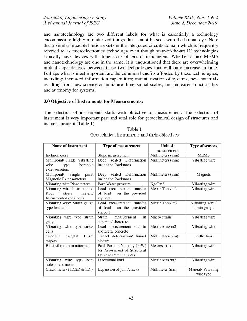
3.0 Objective of Instruments for Measurements:
The selection of instruments starts with objective of measurement. The selection of
instrument is very important part and vital role for geotechnical design of structures and
its measurement (Table 1).
Table 1
Geotechnical instruments and their objectives
Name of Instrument Type of measurement Unit of
measurement
Type of sensors
Inclinometers Slope measurement Millimeters (mm) MEMS
Multipoint/ Single Vibrating
wire type borehole
extensometers
Deep seated Deformation
inside the Rockmass
Millimeters (mm) Vibrating wire
Multipoint/ Single point
Magnetic Extensometers
Deep seated Deformation
inside the Rockmass
Millimeters (mm) Magnets
Vibrating wire Piezometers Pore Water pressure Kg/Cm2 Vibrating wire
Vibrating wire Instrumented
Rock stress meters/
Instrumented rock bolts
Load measurement transfer
of load on the provided
support
Metric Tons/m2 Vibrating wire
Vibrating wire/ Strain gauge
type load cells
Load measurement transfer
of load on the provided
support
Metric Tons/ m2 Vibrating wire /
strain gauge
Vibrating wire type strain
gauge
Strain measurement in
concrete/ shotcrete
Macro strain Vibrating wire
Vibrating wire type stress
cells
Load measurement on/ in
shotcrete/ concrete
Metric tons/ m2 Vibrating wire
Geodetic targets/ Prism
targets
Tunnel deformation/ tunnel
closure
Millimeters(mm) Reflection
Blast vibration monitoring Peak Particle Velocity (PPV)
for Assessment of Structural
Damage Potential m/s)
Meter/second Vibrating wire
Vibrating wire type bore
hole stress meter
Directional load Metric tons /m2 Vibrating wire
Crack meter- (1D,2D & 3D ) Expansion of joint/cracks Millimeter (mm) Manual/ Vibrating
wire type
Journal of Engineering Geology Volume XLIV, Nos. 1 & 2
A bi-annual Journal of ISEG June & December 2019
43
4.0. Description of Instruments:
There are a lot of instruments and it is not possible to describe all of them. Here the
author has tried to describe some major type of instruments being used for tunnel project.
The type and process of installation is well described in the installation manuals for the
instruments. The manuals are to be prepared by supplier and or the end user. The time of
installation is to be described by the design engineer keeping in the view of as close as
possible to the safe measurement. The distance from excavation face for the instrument
installation has been a matter of discussion but it is expected that we should measure all
the possible data with the safety of instrument. It should be on a safe distance from the
face.
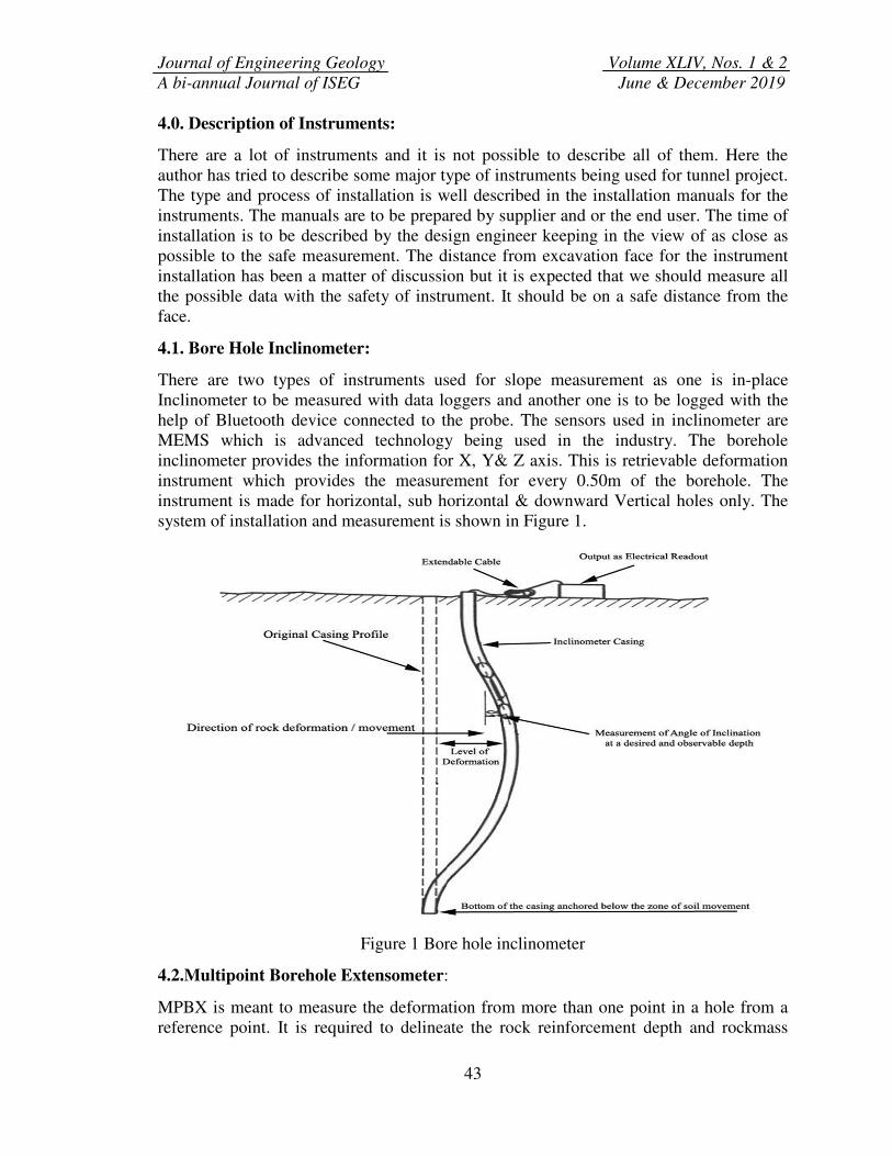
4.1. Bore Hole Inclinometer:
There are two types of instruments used for slope measurement as one is in-place
Inclinometer to be measured with data loggers and another one is to be logged with the
help of Bluetooth device connected to the probe. The sensors used in inclinometer are
MEMS which is advanced technology being used in the industry. The borehole
inclinometer provides the information for X, Y& Z axis. This is retrievable deformation
instrument which provides the measurement for every 0.50m of the borehole. The
instrument is made for horizontal, sub horizontal & downward Vertical holes only. The
system of installation and measurement is shown in Figure 1.
Figure 1 Bore hole inclinometer
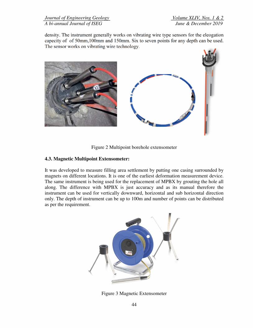
4.2.Multipoint Borehole Extensometer:
MPBX is meant to measure the deformation from more than one point in a hole from a
reference point. It is required to delineate the rock reinforcement depth and rockmass
Journal of Engineering Geology Volume XLIV, Nos. 1 & 2
A bi-annual Journal of ISEG June & December 2019
44
density. The instrument generally works on vibrating wire type sensors for the eleogation
capecity of of 50mm,100mm and 150mm. Six to seven points for any depth can be used.
The sensor works on vibrating wire technology.
Figure 2 Multipoint borehole extensometer
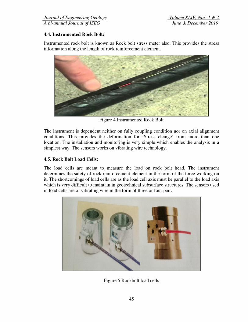
4.3. Magnetic Multipoint Extensometer:
It was developed to measure filling area settlement by putting one casing surrounded by
magnets on different locations. It is one of the earliest deformation measurement device.
The same instrument is being used for the replacement of MPBX by grouting the hole all
along. The difference with MPBX is just accuracy and as its manual therefore the
instrument can be used for vertically downward, horizontal and sub horizontal direction
only. The depth of instrument can be up to 100m and number of points can be distributed
as per the requirement.
Figure 3 Magnetic Extensometer
Journal of Engineering Geology Volume XLIV, Nos. 1 & 2
A bi-annual Journal of ISEG June & December 2019
45
4.4. Instrumented Rock Bolt:
Instrumented rock bolt is known as Rock bolt stress meter also. This provides the stress
information along the length of rock reinforcement element.
Figure 4 Instrumented Rock Bolt
The instrument is dependent neither on fully coupling condition nor on axial alignment
conditions. This provides the deformation for ‘Stress change’ from more than one
location. The installation and monitoring is very simple which enables the analysis in a
simplest way. The sensors works on vibrating wire technology.
4.5. Rock Bolt Load Cells:
The load cells are meant to measure the load on rock bolt head. The instrument
determines the safety of rock reinforcement element in the form of the force working on
it. The shortcomings of load cells are as the load cell axis must be parallel to the load axis
which is very difficult to maintain in geotechnical subsurface structures. The sensors used
in load cells are of vibrating wire in the form of three or four pair.
Figure 5 Rockbolt load cells
Journal of Engineering Geology Volume XLIV, Nos. 1 & 2
A bi-annual Journal of ISEG June & December 2019
46
4.6. Vibrating Wire Piezometer:
Piezometer is meant to measure the pore water pressure. These are installed vertical
(downward & upward) horizontal and sub horizontal axis. The installation is to be
followed as per the descriptions given by the agency or customized by the end user.
Figure 6 Piezometer
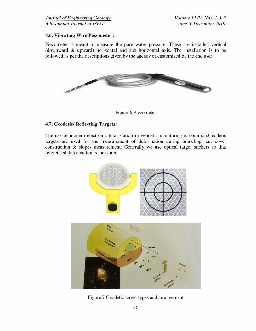
4.7. Geodetic/ Reflecting Targets:
The use of modern electronic total station in geodetic monitoring is common.Geodetic
targets are used for the measurement of deformation during tunneling, cut cover
construction & slopes measurement. Generally we use optical target stickers so that
referenced deformation is measured.
Figure 7 Geodetic target types and arrangement
Journal of Engineering Geology Volume XLIV, Nos. 1 & 2
A bi-annual Journal of ISEG June & December 2019
47
4.8 Crack/ Joint Meters:
Movement across cracks/ joints due to construction activity in surface or underground
excavation and shotcrete is measured by mounting crack meters / crack gauges at critical
locations. The crack meter also provides the information of progressive failure in
rockmass.
Figure 8 3D Crack meter and mechanical crack gauges
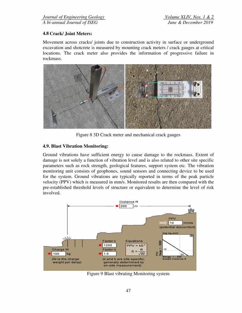
4.9. Blast Vibration Monitoring:
Ground vibrations have sufficient energy to cause damage to the rockmass. Extent of
damage is not solely a function of vibration level and is also related to other site specific
parameters such as rock strength, geological features, support system etc. The vibration
monitoring unit consists of geophones, sound sensors and connecting device to be used
for the system. Ground vibrations are typically reported in terms of the peak particle
velocity (PPV) which is measured in mm/s. Monitored results are then compared with the
pre-established threshold levels of structure or equivalent to determine the level of risk
involved.
Figure 9 Blast vibrating Monitoring system
Journal of Engineering Geology Volume XLIV, Nos. 1 & 2
A bi-annual Journal of ISEG June & December 2019
48
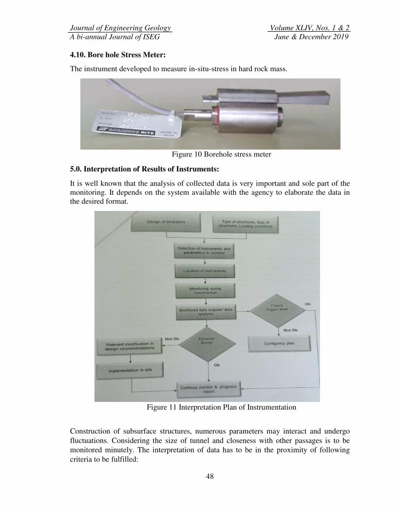
4.10. Bore hole Stress Meter:
The instrument developed to measure in-situ-stress in hard rock mass.
Figure 10 Borehole stress meter
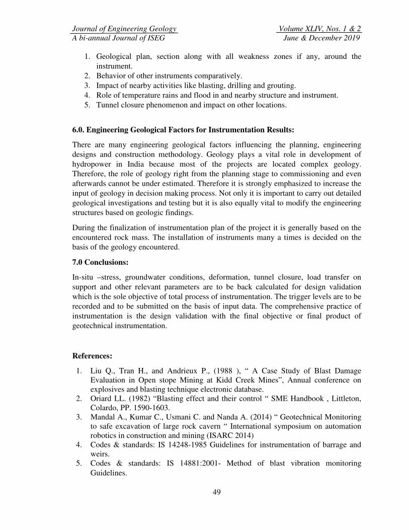
5.0. Interpretation of Results of Instruments:
It is well known that the analysis of collected data is very important and sole part of the
monitoring. It depends on the system available with the agency to elaborate the data in
the desired format.
Figure 11 Interpretation Plan of Instrumentation
Construction of subsurface structures, numerous parameters may interact and undergo
fluctuations. Considering the size of tunnel and closeness with other passages is to be
monitored minutely. The interpretation of data has to be in the proximity of following
criteria to be fulfilled:
Journal of Engineering Geology Volume XLIV, Nos. 1 & 2
A bi-annual Journal of ISEG June & December 2019
49
1. Geological plan, section along with all weakness zones if any, around the
instrument.
2. Behavior of other instruments comparatively.
3. Impact of nearby activities like blasting, drilling and grouting.
4. Role of temperature rains and flood in and nearby structure and instrument.
5. Tunnel closure phenomenon and impact on other locations.
6.0. Engineering Geological Factors for Instrumentation Results:
There are many engineering geological factors influencing the planning, engineering
designs and construction methodology. Geology plays a vital role in development of
hydropower in India because most of the projects are located complex geology.
Therefore, the role of geology right from the planning stage to commissioning and even
afterwards cannot be under estimated. Therefore it is strongly emphasized to increase the
input of geology in decision making process. Not only it is important to carry out detailed
geological investigations and testing but it is also equally vital to modify the engineering
structures based on geologic findings.
During the finalization of instrumentation plan of the project it is generally based on the
encountered rock mass. The installation of instruments many a times is decided on the
basis of the geology encountered.
7.0 Conclusions:
In-situ –stress, groundwater conditions, deformation, tunnel closure, load transfer on
support and other relevant parameters are to be back calculated for design validation
which is the sole objective of total process of instrumentation. The trigger levels are to be
recorded and to be submitted on the basis of input data. The comprehensive practice of
instrumentation is the design validation with the final objective or final product of
geotechnical instrumentation.
References:
1. Liu Q., Tran H., and Andrieux P., (1988 ), “ A Case Study of Blast Damage
Evaluation in Open stope Mining at Kidd Creek Mines”, Annual conference on
explosives and blasting technique electronic database.
2. Oriard LL. (1982) “Blasting effect and their control “ SME Handbook , Littleton,
Colardo, PP. 1590-1603.
3. Mandal A., Kumar C., Usmani C. and Nanda A. (2014) “ Geotechnical Monitoring
to safe excavation of large rock cavern “ International symposium on automation
robotics in construction and mining (ISARC 2014)
4. Codes & standards: IS 14248-1985 Guidelines for instrumentation of barrage and
weirs.
5. Codes & standards: IS 14881:2001- Method of blast vibration monitoring
Guidelines.
Journal of Engineering Geology Volume XLIV, Nos. 1 & 2
A bi-annual Journal of ISEG June & December 2019
50
6. ASTM : 6230- Standard test method for monitoring ground movement using probe
type inclinometer.
7. ASTM: 4403- Standard Practice for Extensometers used in Hard Rock.
8. Bieniawski, Z.T.(1979). The geomechanics classification rock engineering
applications. Proc. 4th
Int. Congr. Rock Mech., ISRM, Montreux, 1979, vol.2, 41-48.
9. Bieniawski, Z.T. 1989.Engineering rock mass classification.:Jhon Wiley & Sons.
New York, 272 p.
10. Terzaghi, K. (1946). Rock defects and loads on tunnel supports. Rock Tunnelling
with Steel Supports. Ed. R.V. Proctor and T. White, Commercial Shearing
Co.Younstown, OH, 15-19.
11. Codes & standards : IS 7356 (Part-I) -2002: Code of practice for installation,
Maintenance and observation of instruments for pore pressure measurement in
Earth Dam and Rock fill Dams, Porous tube Piezometers.