important replacement parts for model series rg , rp, … · apa apb apc apd ape apf apg aph api...
TRANSCRIPT

Form RZ-NA-P-RG/RP/RBL, Page 1
IMPORTANT1. Always include complete heater model and serial number so that
any specification change can be considered for parts shipment. Itcan save time and expense.
2. Specifications are subject to change without notice.3. We reserve the right to substitute functional replacements.4. Order by Part No.; not Heater Option Designation.
Replacement Parts For Model Series RG,RP, HRPD, RGB, RPB, RGBL, RPBL,
RPDBL, PGBL, RBA, RBHA, and RBL(including prefixes "C", "H", and "HC")
� Form P-RG/RP/RBL (Version A)Obsoletes Form P-RG/RP/RBL
Duct Furnace Models
Packaged Models
Blower Cabinets
RG
RP
HRPD
RGB
RGBL
RPB
RPBL
RPDBL
RBA
PGBL
RBHA
RBL
Subject .................................................................................................................................................... FormInstallation/Operation - Model Series PGBL, RGBL, RPBL, RPDBL Packaged Systems ...... I-PGBL/RGBL/RPBLInstallation/Operation - Model Series RG and RP Duct Furnaces ............................................. I-OUTDOOR DUCTInstallation/Operation - Model Series RGB and RPB Packaged Systems ........................................... I-XE/RGB/RPBInstallation - Models RBL, RBA, RBHA Blower Cabinets ................................................................................... I-RBLLimited Warranty ............................................................................................................................................................ WReplacement Components for Evaporative Cooling Modules ...........................................................................P-RECReplacement Gas Valves and Ignition Controllers ......................................................................................... P-VALVESReplacement Thermostats .............................................................................................................................. P-T'STATSConverting to Other Gases ........................................................................................................................................ P-GC
References (Downloadable forms available at www.RezSpec.com):
Parts Index by Type and ModelIndoor
RG RP HRPD RGB RPB RGBL RPBL RPDBL PGBL RBA RBHA RBLBlowers and Components -- -- -- 22 22 24 24 24 24 51 51 51Burner Rack and Carryovers 18 18 18 18 18 18 18 18 18 -- -- --Cabinet Parts (Blower Section/Cabinet) -- -- -- 21 21 23 23 23 23 51 51 51Cabinet Parts (Furnace Section) 12 14 14 12 14 12 14 14 16 -- -- --Carryover Regulator 18 18 18 18 18 18 18 18 18 -- -- --Contactor -- -- -- 9 9 9 9 9 9 9 9 9Cooling Coil Cabinet (Option AU) -- -- -- 48 48 48 48 -- -- -- -- --Cooling Coil Curbs -- -- -- 46 46 46 46 46 -- 46 46 46Dampers & Controls, Discharge -- -- -- 47 47 47 47 47 -- -- -- 47Dampers & Controls, Inlet -- -- -- 26 26 26 26 26 26 26 26 26Direct Digital Control Components -- -- -- 11 11 -- -- -- -- -- -- --Directional Air Baffles (Heat Exchanger) 17 17 17 17 17 17 17 17 17 -- -- --Disconnect Switch 45 45 45 45 45 45 45 45 45 45 45 45Downturn Plenum Cabinet -- -- -- 47 47 47 47 47 -- -- -- --Drive Components (Belts and Pulleys) -- -- -- 35 35 40 40 * 40 35 42 40Electrical Component Locations 6 6 6 6-7 6-7 6-7 6-7 6-7 6-7 7 7 7Evaporative Cooling ModulesFan Control 9 9 9 9 9 9 9 9 9 9 9 9Filter Racks -- -- -- 22 22 23 23 23 23 51 -- 51Filters -- -- -- 43 43 43 43 43 43 43 -- 43Firestat -- -- -- 8 8 8 8 8 8 -- -- --Flue Restrictors 12 -- -- 12 -- 12 -- -- -- -- -- --Furnace Couplings -- -- -- -- -- 12 14 14 16 -- -- --Heat Exchanger 17 17 17 17 17 17 17 17 17 -- -- --Limit Controls and Shields 9 9 9 9 9 10 10 10 10 -- -- --Manifold, Special (FM, Illinois School) 18 18 -- 18 18 18 18 18 18 -- -- --Manifold, Standard 18 18 18 18 18 18 18 18 18 -- -- --Motors (Blower) -- -- -- 30 30 30 30 30 30 30 30 30Motors (Venter) 14 14 14 14 14 16Pilots 11 11 11 11 11 11 11 11 11 -- -- --Pressure Switch (Combustion Air) -- 8 8 -- 8 -- 8 8 8 -- -- --Pressure Switch (Dirty Filter) -- -- -- 9 9 9 9 9 9 -- -- --Pressure Switch (Gas) 9 9 9 9 9 9 9 9 9 -- -- --Rating Plate and Serial No. 2 2 2 2 2 2 2 2 2 2 2 2Relay Chart 5 5 5 5 5 5 5 5 5 -- -- --Remote Console (Option RC) 45 45 45 45 45 45 45 45 45 -- -- --Spark ignition control -8- -- -- 30 30 30 30 30 30 30 30 30Switches, Toggle 11 11 11 11 11 11 11 11 11 11 11 11Transformer Chart 5 5 5 5 5 5 5 5 5 5 5 5Valves (Electric Gas Valves)Valves (Manual Gas Valves) 19 19 19 19 19 19 19 19 19 -- -- --Variable Frequency Drive -- -- -- 30 30 30 30 30 30 -- -- --Vent Cap 12 -- -- 12 -- 12 -- -- -- -- -- --Venters -- 14 14 -- 14 -- 14 14 16 -- -- --Vertical Vent Kit (Option CC3) -- 14 14 -- 14 -- 14 -- -- -- -- --Weatherhoods (Outside Air Hood) -- -- -- 46 46 46 46 46 46 46 -- 46*Special; contact distributor.
Reference: See Parts Form P-REC (Applies to both Model REC and AS Options)
Reference: See Parts Form P-VALVES (gas valves are identified by Serial No.)
Special Order - Contact your Distributor.
Most page references are first page only; info my continue on following pages.
Blower Cabinet (See Description, page 50.)
Duct FurnacesO utdoor
Packaged Units [Furnace(s) & Blower] O utdoor
ITEMS THAT ARE HIGHLIGHTED ARE POPULAR ITEMSITEMS WITH CONVERSATION BUBBLE GIVE MORE INFORMATION
Form RZ-NA-P-RG/RP/RBL, Page 2
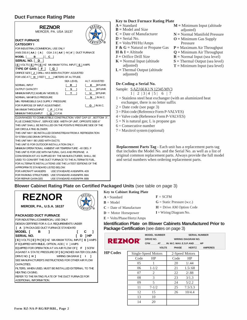
Blower Cabinet Rating Plate on Certified Packaged Units (see table on page 3)Key to Cabinet Rating PlateA = StandardB = ModelC = Date of ManufactureD = Motor HorsepowerE = Volts/Phase/Hertz/Amps
F = SCFMG = Static Pressure (w.c.)H = Drive AM Option CodeI = Wiring Diagram No.
Duct Furnace Rating Plate
De-Coding a Serial No.Sample: S AZJ 66 K1 N 12345 MV3
1 | 2 | 3 | 4 | 5 | 6 | 71 = Stainless steel heat exchanger (with an aluminized heat
exchanger, there is no letter suffix2 = Date code (see page 3)3 = Pilot code (Reference Form P-VALVES)4 = Valve code (Reference Form P-VALVES)5 = N is natural gas; L is propane gas6 = Consecutive number7 = Maxitrol system (optional)
Key to Duct Furnace Rating PlateA = StandardB = Model and SizeC = Date of ManufacturerD = Serial No.E = Volts/PH/Hz/AmpsF & G = Natural or Propane GasH & I = AltitudeJ = Orifice Drill SizeK = Normal Input (altitude
adjusted)L = Thermal Output (altitude
adjusted)
M = Minimum Input (altitudeadjusted)
N = Normal Manifold PressureO = Minimum Gas Supply
PressureP = Maximum Air ThroughputQ = Minimum Air ThroughputR = Normal Input (sea level)S = Thermal Output (sea level)T = Minimum Input (sea level)
Replacement Parts Tag - Each unit has a replacement parts tagthat includes the Model No. and the Serial No. as well as a list oforiginal common replacement parts. Always provide the full modeland serial numbers when ordering replacement parts.
Identification Plate on Blower Cabinets Manufactured Prior toPackage Certification (see dates on page 3)
HP Codes
�
MODEL NUMBER SERIAL NUMBER
DRIVE NO. WIRING DIAGRAM NO.
CFM _____ AT____ IN. W.C. MAX. E.S.P. AND ____ HP
VOLTS PHASE HERTZ AMPERES
Single-Speed Motors 2-Speed MotorsCode HP Code HP
05 1 20 1/.4406 1-1/2 21 1.5/.6807 2 22 2/.8808 3 23 3/1.309 5 24 5/2.211 7-1/2 25 7.5/3.312 15 26 10/4.413 1014 20
REZNORMERCER, PA. USA 16137
DUCT FURNACECATEGORY IFOR INDUSTRIAL/COMMERCIAL USE ONLYANSI Z83.8 [ AA ] - [ A ] CGA 2.6 [ AA' ] -M [ A' ] DUCT FURNACEMODEL [ B ] [ C ]SERIAL NO. [ D ][ E ] VOLTS [ E ] PH [ E ] HZ MAXIMUM TOTAL INPUT [ E ] AMPSTYPE OF GAS: [ F ] [ G ]ORIFICE SIZE [ J ] DRILL HAS BEEN FACTORY ADJUSTEDFOR USE AT [ H ] FEET [ I ] METERS OF ALTITUDE.
ALT. ADJUSTEDNORMAL INPUT [ K ]BTU/HR.OUTPUT CAPACITY [ L ]BTU/HR.MINIMUM INPUT(2,M,MB,MV MODELS) [ M ]BTU/HR.NORMAL MANIFOLD PRESSURE [ N ] IN.W.C.MIN. PERMISSIBLE GAS SUPPLY PRESSURE FOR PURPOSE OF INPUT ADJUSTMENT. [ O ] IN.W.C.MAXIMUM THROUGHPUT [ P ] C.F.M.MINIMUM THROUGHPUT [ Q ] C.F.M.CLEARANCES TO COMBUSTIBLE CONSTRUCTION: VENT CAP-10' , BOTTOM- 3",FLUE CONNECTION-6", SERVICE SIDE- WIDTH OF UNIT, OPPOSITE SIDE-6"THIS UNIT SHALL BE INSTALLED ON THE POSITIVE PRESSURE SIDE OF THEAIR CIRCULATING BLOWER.THIS UNIT MAY BE INSTALLED DOWNSTREAM FROM A REFRIGERATIONSYSTEM (USE DRAIN OPTION CS1).THIS UNIT MAY BE USED WITH DUCTS.THIS UNIT IS FOR OUTDOOR INSTALLATION ONLY.MINIMUM OPERATIONAL AMBIENT AIR TEMPERATURE: -40 DEG. FTHIS UNIT IS FOR USE WITH NATURAL GAS AND PROPANE. A CONVERSION KIT AS SUPPLIED BY THE MANUFACTURER, SHALL BE USED TO CONVERT THIS DUCT FURNACE TO THE ALTERNATE FUEL.FOR ALTERNATE INSTALLATIONS USE THE LATEST EDITIONS OF THEAPPROPRIATE STANDARD LISTED BELOW:FOR AIRCRAFT HANGERS USE STANDARD ANSI/NFPA 409FOR PARKING STRUCTURES USE STANDARD ANSI/NFPA 88AFOR REPAIR GARAGES USE STANDARD ANSI/NFPA 88B
SEA LEVEL[ R ][ S ][ T ]
REZNORMERCER, PA., U.S.A. 16137
PACKAGED DUCT FURNACEFOR INDUSTRIAL/COMMERCIAL USE ONLYDESIGN CERTIFIED FOR A.G.A REQUIREMENTS UNDER [ A ] PACKAGED DUCT FURNACE STANDARDMODEL [ B ] [ C ]SERIAL NO. [ D ] HP[ E ] VOLTS [ E ] PH [ E ] HZ MAXIMUM TOTAL INPUT [ E ] AMPSIF EQUIPPED WITH R.E.C. OPTION, ADD [ V ] AMPSEQUIPPED FOR OPERATION AT AN AIR FLOW OF [ F ] SCFMAGAINST A STATIC PRESSURE OF [ G ] INCHES WATER COLUMN.DRIVE NO. [ H ] WIRING DIAGRAM [ I ]SEE MANUFACTURER'S INSTRUCTIONS FOR OTHER AIR FLOWCAPACITIES.FILTERS, WHEN USED, MUST BE INSTALLED EXTERNAL TO THE HEATING CASING.REFER TO THE RATING PLATE OF THE DUCT FURNACE FOR ADDITIONAL INFORMATION.

Form RZ-NA-P-RG/RP/RBL, Page 3
Date Series was Introduced orRecertified (may affect parts selection)
First Element of the Serial Number - Date of ManufactureYear Jan Feb Mar Apr May June July Aug Sept Oct Nov Dec1989 AOA AOB AOC AOD AOE AOF AOG AOH AOI AOJ AOK AOL1990 APA APB APC APD APE APF APG APH API APJ APK APL1991 AQA AQB AQC AQD AQE AQF AQG AQH AQI AQJ AQK AQL1992 ARA ARB ARC ARD ARE ARF ARG ARH ARI ARJ ARK ARL1993 ASA ASB ASC ASD ASE ASF ASG ASH ASI ASJ ASK ASL1994 ATA ATB ATC ATD ATE ATF ATG ATH ATI ATJ ATK ATL1995 AUA AUB AUC AUD AUE AUF AUG AUH AUI AUJ AUK AUL1996 AVA AVB AVC AVD AVE AVF AVG AVH AVI AVJ AVK AVL1997 AWA AWB AWC AWD AWE AWF AWG AWH AWI AWJ AWK AWL1998 AXA AXB AXC AXD AXE AXF AXG AXH AXI AXJ AXK AXL1999 AYA AYB AYC AYD AYE AYF AYG AYH AYI AYJ AYK AYL2000 AZA AZB AZC AZD AZE AZF AZG AZH AZI AZJ AZK AZL2001 BAA BAB BAC BAD BAE BAF BAG BAH BAI BAJ BAK BAL2002 BBA BBB BBC BBD BBE BBF BBG BBH BBI BBJ BBK BBL2003 BCA BCB BCC BCD BCE BCF BCG BCH BCI BCJ BCK BCL2004 BDA BDB` BDC BDD BDE BDF BDG BDH BDI BDJ BDK BDL2005 BEA BEB BEC BED BEE BEF BEG BEH BEI BEJ BEK BEL2006 BFA BFB BFC BFD BFE BFF BFG BFH BFI BFJ BFK BFL2007 BGA BGB BGC BGD BGE BGF BGG BGH BGI BGJ BGK BGL2008 BHA BHB BHC BHD BHE BHF BHG BHH BHI BHJ BHK BHL2009 BIA BIB BIC BID BIE BIF BIG BIH BII BIJ BIK BIL2010 BJA BJB BJC BJD BJE BJF BJG BJH BJI BJJ BJK BJL2011 BKA BKB BKC BKD BKE BKF BKG BKH BKI BKJ BKK BKL2012 BLA BLB BLC BLD BLE BLF BLG BLH BLI BLJ BLK BLL2013 BMA BMB BMC BMD BME BMF BMG BMH BMI BMJ BMK BML2014 BNA BNB BNC BND BNE BNF BNG BNH BNI BNJ BNK BNL2015 BOA BOB BOC BOD BOE BOF BOG BOH BOI BOJ BOK BOL2016 BPA BPB BPC BPD BPE BPF BPG BPH BPI BPJ BPK BPL2017 BQA BQB BQC BQD BQE BQF BQG BQH BQI BQJ BQK BQL2018 BRA BRB BRC BRD BRE BRF BRG BRH BRI BRJ BRK BRL2019 BSA BSB BSC BSD BSE BSF BSG BSH BSI BSJ BSK BSL2020 BTA BTB BTC BTD BTE BTF BTG BTH BTI BTJ BTK BTL2021 BUA BUB BUC BUD BUE BUF BUG BUH BUI BUJ BUK BUL2022 BVA BVB BVC BVD BVE BVF BVG BVH BVI BVJ BVK BVL2023 BWA BWB BWC BWD BWE BWF BWG BWH BWI BWJ BWK BWL2024 BXA BXB BXC BXD BXE BXF BXG BXH BXI BXJ BXK BXL2025 BYA BYB BYC BYD BYE BYF BYG BYH BYI BYJ BYK BYL2026 BZA BZB BZC BZD BZE BZF BZG BZH BZI BZJ BZK BZL
Duct Furnace CertificationOriginal Recertified
Model Agency Introduced Series
(H)(C)(HC) RP A.G.A. 2/90 --(H) RP A.G.A. -- Series 8 - 5/95(H)(C)(HC) RG A.G.A. 2/90 Series 8 - 5/95(H) RG C.G.A. 5/90 Series 8 - 5/95(H) RP C.G.A. 5/90 Series 8 - 5/95
Packaged Unit CertificationModel Original Agency Certified
(H)(C)(HC) RGB A.G.A. 2/96(H) RPB A.G.A. 2/96RPBL, (C)RGBL A.G.A. 11/96PGBL A.G.A. 3/97(H)(C)(HC) RGB C.G.A. 8/96(H) RPB C.G.A. 8/96RPBL, (C)RGBL C.G.A. 8/97PGBL C.G.A. 8/97
Beginning January 2000, heaters display a CSA label cer-tifying that the unit or system has been approved to ANSIStandards for use in the United States or to C.G.A. Stan-dards for use in Canada.
PGBL 3 Packaged 400-1200 MBH Input/ 80% Power IndoorSystem 3300-13500 CFM only
RG 11 Duct Furnace 75-400 MBH Input 78% Gravity OutdoorRGB 11 Packaged 75-400 MBH Input/ 78% Gravity Outdoor
System 600-7100 CFMRGBL 7 Packaged 400-1200 MBH Input/ 78% Gravity Outdoor
System 3300-13500 CFMRP 9 Duct Furnace 125-400 MBH Input 80% Power OutdoorRPB 9 Packaged 125-400 MBH Input/ 80% Power Outdoor
System 1025-7100 CFMRPBL 7 Packaged 400-1200 MBH Input/ 80% Power Outdoor
System 3300-13500 CFMRPDBL 5 Packaged 800-1600 MBH Input/ 80% Power Outdoor
System 6600-22000 CFMRBA 1 Blower only 1500-5000 CFM -- -- Indoor/OutdoorRBHA 1 Blower only 1500-5000 CFM -- -- Indoor/OutdoorRBL 1 Blower only 5000-15000 CFM -- -- Indoor/Outdoor
Descriptions of Currently Manufactured Models (Prefix "H"indicates higher CFM capacity; "C" indicates higher thermal efficiency;"HC" indicates higher CFM capacity and thermal efficiency)Model No.Series of Type Capacity Ranges Vent Installation
Sizes The
rmal
Eff
icie
ncy

Form RZ-NA-P-RG/RP/RBL, Page 4
Dual Duct Furnace and Packaged System (Blower/Furnace(s)) Model Configurations
��������
� �� ����
�����
NOTE: Left side controls (illustrated)are standard. Right side controls areoptional. If the unit has right sidecontrols, some replacement parts willbe affected.
Unit Direction Orientation Diagram -Applies to all models; Model PGBL 800 illustrated
Outdoor (H)(C)RGB and (H)RPB Packaged Systems
"B"CabinetDuctFurnace
"BL"Cabinet
DuctFurnaceDuctFurnaceDuctFurnace
"BL"Cabinet
DuctFurnaceDuctFurnace
Packaged Includes One Size 400 Duct FurnaceModel Series Size 250 300 350 400RGBL/RPBL/PGBL 400 -- -- -- 1
Packaged Includes Size & Quantity of FurnacesModel Series Size 250 300 350 400RGBL/RPBL 500 2 -- -- --RGBL/RPBL 600 -- 2 -- --RGBL/RPBL 700 -- -- 2 --RGBL/RPBL/PGBL 800 -- -- -- 2
Packaged Includes Size & Quantity of FurnacesModel Series Size 250 300 350 400RGBL/RPBL 1050 -- -- 3 --RGBL/RPBL/PGBL 1200 -- -- -- 3
"BL"Cabinet
DuctFurnace
Indoor PGBL Packaged System1. A PGBL packaged system is a duct furnace (in quantity and size
indicated below) coupled together with a "BL" Blower Cabinet.2. Optional downturn plenum, coil cabinet (with or without down-
turn), and evaporative cooling module may be part of the pack-aged unit.
Outdoor (C)RGBL and RPBL Packaged Systems1. Model HRG, HCRG, or HRP duct furnaces (in quantity and size
indicated below) coupled together with a "BL" Blower Cabinet.2. Optional outside air hood, downturn plenum, coil cabinet (with or
without downturn), and evaporative cooling module may be partof the packaged unit.
Outdoor RPDBL Packaged Systems1. HRP duct furnaces (in quantity and size indicated below) coupled together with two "BL" Blower Cabinets.2. Optional outside air hoods and downturn plenum cabinets may be part of the packaged unit.
"BL"Cabinets
DuctFurnaces
Size 800 Sizes 1000/1200/1400/1600
"BL"Cabinets
DuctFurnaces
RPDBL Consists of:800 (2) RPBL 400 Packaged Systems1000 (2) RPBL 500 Packaged Systems1200 (2) RPBL 600 Packaged Systems1400 (2) RPBL 700 Packaged Systems1600 (2) RPBL 800 Packaged Systems
NOTE: Replacement parts are not identified for thesespecific models; look for equivalent RPBL models.
1. Model RG, CRG, HRG, HCRG, RP, or HRPduct furnace coupled together with a "B" BlowerCabinet.
2. Optional outside air hood, downturn plenum,coil cabinet (with or without downturn), andevaporative cooling module may be part of thepackaged unit.
Outdoor Dual Duct Furnaces in Series,Model HRPD 250, 300, 350, 400, 500, 600, 700, 800
250 = 2(HRP125); 300 = 2(HRP150);350 = 2(HRP175); 400 = 2(HRP200);500 = 2(HRP250); 600 = 2(HRP300);700 = 2(HRP350); 800 = 2(HRP400)

Form RZ-NA-P-RG/RP/RBL, Page 5
Line Voltage Application to Package ConfigurationLine Voltage to Furnace or Packaged System
Unit Voltage 115 208 230 460 575 CommentsRG Control Volts In/Out/VA 115/24/20 208/24/20 230/24/20 460/24/20 N/A Furnace onlyRGB Motor Voltage 115 208 230 460 575RGB Controls Volts In/Out/VA 115/24/40 208/24/40 230/24/40 460/24/40 575/24/200RP Control Volts In/Out/VA 115/24/40 208/24/40 230/24/40 460/24/40 N/A Furnace onlyRPB Motor Voltage 115 208 230 460 575RPB Controls Volts In/Out/VA 115/24/40 208/24/40 230/24/40 460/24/40 115/24/40 575 to 115V / 300VA TransformerRPBL/RGBL/PGBL 400 115 208 230 460 115 575 to 115V / 300VA TransformerRPBL/RGBL 500-800; PGBL 800 115 208 230 460 115 575 to 115V / 500VA TransformerRPBL/RGBL 1050-1200; PGBL 1200 115 208 230 460 115 575 to 115V / 750VA Transformer
Quick Reference Charts (Note: Consult wiring diagram to verify relays and transformers.)
Transformer Chart
In Out VA103054 115 24 20 X103055 115 24 40 X X X X X X103497 208-230 24 40 X X X 103498 480 24 40 X X X38634 115 24 200 X39095 208-230-460-575 24 200 X X X X
105202 208-230-460-575 115 300 X X X X X86998 208 115 500 X86997 230-460 115 500 X
112641 575 115 500 X112642 575 115 750 X
PGB
L C
ontr
ols
RG
Con
trol
s
RP
Con
trol
s
RG
B(L
) Con
trol
s
RPB
(L)C
ontr
ols
Tra
nsfo
rmer
P/N
Dis
char
ge D
ampe
r
RB
HA
/RB
A/R
BL
C
ontr
ols
575V
Lin
e R
PBL
400-
800;
PG
BL
800
/120
0
575V
Lin
e R
PBL
10
50-1
200
575V
Lin
e R
PBL
/PG
BL
400
IRI M
anifo
ld
Use
d in
Opt
ion
D1-
4 (D
DC
fro
m
build
ing'
s env
iron
-m
enta
l con
trol
sy
stem
)
FM M
anifo
ldTransformer Volts
Relay ChartWhere Used 103317 98118 110656 46233 209164 206146Freezestat Relay XStarter Relay XSummer/Winter Relay (Option BF2) XSPST Relay, Option BG2 XSPDT Relay, Option BG3 XSPST Relays, Option BG4 X(2)SPST and SPDT Relay, Option BG5 X XIllinois School Code Controls (Option BM12) X XTwo-Speed Motor Relay XTwo-Speed Motor Speed Relay XIRI Gas Controls (Option BM13) X(4)Discharge Damper X(2)Time Delay Relay Venter (RP Series & PGBL) XBlower Relay XDDC Interface Relay (Options D1, 2, 3, 4) X (2or3)Fan/Blower Control (replaced temperature activated fan control 12/04) XGas Control Options AG39, AG40, AG41, AG42 X
For additional information, see CODE(S): 21, 36 34, 35 33 12 14B 92On Page 9, 10 10 10 9 9 15
Relay P/N

Form RZ-NA-P-RG/RP/RBL, Page 6
��������� ��������������������
Furnace Electrical Component Locations("B" Cabinet is illustrated; control locations arethe same in the larger capacity "BL" Cabinets)
Code Description P/N1A Electrical Box 1001081B Electrical Box Cover 1001092 Freezestat, Auto Reset (Option BE2) 1261703A Combustion Air Pressure Switch 201327
- Replacement switch depends on the dateof manufacture and original equipment; seepage 8 before selecting.
3B Combustion Air Pressure Switch (PGBL) 201327- Replacement switch depends on the dateof manufacture; see page 8 before selecting.
4 Discharge Air Firestat (Option BD2) 427825A Ignition Controller (Recycle G67BG-5) 977825B Ignition Controller (Lockout G770NGC-4) 975476 Discharge Air Sensor (modulating gas cntrls) 480417A 2-Stage Controller (for Option AG3) 417007B 2-Stage Ductstat Sensor Holder (AG15-20) 1158507C Remote Ductstat Modules (AG15-20) - see page 8.8 Main Low Gas Pressure Switch (Opt BP3) See9 Pilot Low Gas Pressure Switch (Opt BP3) page 9.10 Main High Gas Pressure Switch (Opt BP2) 9385011 Gas Pressure Switches in Opt AG39, AG40, AG41,
and AG42 - location not shown; see page 9.12 Time Delay Relay (RP Series) 4623313A Limit Control RG(B) & RP(B) only 50417
(for BL systems, see page 10)13B Limit Control RP/HRPD with Opt BU2 196571
only (140°F, Green)13C Limit Shield RG(B) & RP(B) only 1222914A Fan Control - Effective 12/04, a temperature 209184
activated fan control is no longer available.Order the P/N listed for a Replacement Kit.
14B Fan Control Time Delay Relay (on units 209164mfgd beginning 12/04; check wiring diagram)
NOTE: See pages 8 - 10 for illustrations and additionalinformation about the furnace electrical components listed below.
Venter assembly and combustionair switch on indoor Model PGBLis on top of the unit.
Optional DownturnPlenum Cabinet
Code Description P/N15 Freezestat Time Delay Relay 8966116 Line Voltage Terminal Blocks 14497217 Line Voltage Terminal Block Adapter 14497318 Heat Shield (on units (used in U.S.) 10188
mfgd prior to 12/04) (used in Canada) 6381819 Low Voltage Terminal Blocks (See Code 16) 14497220 Low Voltage Terminal Block Adapter 14497321 Freezestat Relay 10331722 Dirty Filter Pressure Switch 105507
*Code 3A - Beginning with units manufactured 2/99, the pressureswitch on RP Series units is mounted inside the electrical box. Priorto 2/99, the pressure switch is mounted on the wall of the electricalcompartment above the electrical box. See page 8 for replacementinformation.
3B

Form RZ-NA-P-RG/RP/RBL, Page 7
Blower Cabinet Electrical Component Location ("B" Cabinet is illustrated; control locations arethe same in the larger capacity "BL" Cabinets)
Optional DownturnPlenum Cabinet
Code Description P/N25 Fuse Holder (Fuse, see page 9) 6024126 Convenience Outlet 9691227A Blower Motor Contactor - 24V Coil 119625
(replaces P/N 93661)27B Blower Motor Starters - see pages 30 - 3528 Temperature Controller (Options AG41, AG42) 19720429 High Ambient Limit Control (Opt BN2) 12617030 Outside Air or Return Air Controller 126170
or P/N 197204, J/C A19ABC-2431 Mixed Air Controller 1610932 Potentiometer 1611033 Starter Relay (replaces 105803) 11065634 Summer Winter Relay (Option BF2) 9811835 RBM Relay (Option BG2, BG4) 9811836 RBM Relay (Option BG3, BG5) 10331737 2-Speed Motor Speed Selector Relay - See CODE 33 11065638 Auto Reset Reverse Flow Limit 10332339 Return Air Firestat (Option BD3); See CODE 4 4278240 Low Voltage Terminal Blocks 14497241 Low Voltage Terminal Block Adapters 14497342A Control 115V to 24V, 20VA 103054and and 115 to 24V, 40VA 10305542B Damper 208/230 to 24V, 40VA 103497
Transformers 460 to 24V, 40VA 103498(See 208 to 24V, 200VA 39094Chart on 230/460/575 to 24V, 200VA 39095page 5) 230/460/575 to 115V, 300VA 105202
208 to 115V, 500VA 86998230/460 to 115V, 500VA 86997
575 to 115V, 500VA 112641575 to 115V, 750VA 112642
43 Air Proving Switch 11210744A Blower Cabinet Electrical Box - std left side controls 100092
Blower Cab Elctrcl Box - optional right side controls 9548644B Electrical Box Cover 10009544C Electrical Box Top 196648
Reference NOTE: Except where a page number is listed, see pages 8-10for illustrations and additional information about electrical components.Building Management Control NOTE: If equipped with Option D1-D4for DDC interface to the building's computerized environmental controlsystem, the dotted line indicates the location of the electrical box that housesthe specially programmed Johnson Control Metasys® control unit. BoxCover is P/N 171739. Other components are listed on page 11.
See Note at the bottom of thepage about building manage-ment control option.

Form RZ-NA-P-RG/RP/RBL, Page 8
Code 2 - Freezestat, J/C #AI9AAF-12C, 25-225oF, P/N 126170,(replaces P/N 16108)
For RP Series Models manufactured prior to 12/91 (SerialNo. Date Code AQL) order Replacement Pressure SwitchKit, P/N 93033.
Electrical Components - See location drawings on pages 6-7.Code 1 - Electrical Box and Cover(in the electrical compartment)
Electrical Box, P/N 100108(replaces 11965 on Model RG)
Electrical BoxCover, P/N 100109
(replaces P/N 9546 onModel RG)
Code 3 - Combustion Air Switch - Replacementdepends P/N on date of manufacture and altitude.
Codes 4 & 39 - Firestat, Honeywell #L4029E1029, Manual reset opens at 200°F, P/N 42782
Firestat Gasket,P/N 121041 (used whenfirestat is installed less cover)Firestat Shield, P/N120021 (used with dischargefirestat only)
Code 5A -RecyclingIgnitionController,J/C G67BG-5,P/N 97782
Code 5B - IgnitionController withlockout (120second timing),J/C G770NGC-4,P/N 97547
Location and Components for InstallingDischarge Sensor in Code 7A
Code 6, Discharge Sensor forModulating Gas ValveMaxitrol TS-121, P/N 48041,for Option AG8 and AG9P/N 133228, Maxitrol TS-194for Options AG39 and AG41
Code 7A, Two-StageDuctstat, HoneywellT678A1015,P/N 41700
55-58°F, Capillary Length 5' -Used in Gas Control OptionsAG3, AG4, and AG5Bulb Holder, P/N 100260Cable Strap, P/N 16227
Gasket,P/N 104138
Bulb Clamp,P/N 100260
For units mfgd beginning 7/04, for altitudes to 4000ft, P/N 204327, setpoint 0.58 ± .05" w.c. ; foraltitudes above 4000 ft, order P/N 204328, setpoint0.52 ± .05" w.c.
Grommet Clamp, P/N 131993Cable Clamp, P/N 132065
������������������
������������
������ ��!"�����#$$�%$&
'�(����
���
)�*"���������%
'� ���+
&������(��!"�����#$$�%$�*���',-�������.#�$$����/��!�/��0(+1���+2�34�/*����',-�������.#�$$����/��!�/��0(+�**��'�� �����������������(��!"������*#$.#5%3
6������!���0/!�2��"7
For RP Series units mfgd between 12/91 and 7/04(except RP/RPB Models with Option AG39/40 or 1stfurnace of Models HRPD/RPBL with Option AG41/42 modulating gas controls), for altitudes to 4000 ft,order replacement kit P/N 193810; for altitudesabove 4000 ft, order P/N 193811.For RP/RPB Models mfgd between 12/91 and 7/04with Option AG39/40 and 1st furnace of ModelsHRPD/RPBL with Option AG41/42 gas controls,P/N 193813 for RP(B) Sizes 125-225 and HRPD 250-400 or PN 193812 for RP(B) Sizes 250-400, HRPD500-800, and all RPBL.
CODE 5 A
CODE 5B
IF EXISTING CONTROLLOOKS LIKE THIS, YOUMUST USE KIT # WB-31172
IF EXISTING CONTROL LOOKS LIKE THIS, YOU MUST USE KIT # WB-31173
IF EXISTING CONTROL LOOKS LIKE THIS (BELOW) YOU CAN USE REPLACEMENT PART # WB-31167
IF EXISTING CONTROL LOOKS LIKE THIS (BELOW)YOU CAN USE REPLACEMENT PART # WB-31168

Form RZ-NA-P-RG/RP/RBL, Page 9
����'���+�8�����/����
��0/�������8�
�����������)�*��8�
������+)�*��2���**/���2��!��9������(��#3#:23!3����#�.;$<
����)=<�.$�.#�.�2����*�����0�!�/����6���0(�����##�$=7� �!"/ )�*��2���**/���2��!��>��2��(�#3.:23!3����#�5<;5����)=<�.$�.#�.�2�������������6���0(��������##�$=7����������2���*��2 ��**/��*2��!��*2������2�����(��#3#:23!3����#�.;$<
Vent Limiter,Maxitrol A1209,P/N 123481
Codes 8, 9, 10 - Gas Pressure Switches
Bracket, P/N 100261
Code 10 - High GasPressure Switch,P/N 93850, ManualReset, Settings -125% of normalmanifold gaspressure as stated onthe unit rating plate
Codes 8 & 9 - Low GasPressure Switch, P/N 93849(Range 1-6" w.c.); P/N149176 (Range 6-24" w.c.)Automatic Reset, Settings -50% of minimum inlet gaspressure as stated on theunit rating plate
Code 12 - Time DelayRelay, TI 60000GO-17,P/N 46233
20- seconddelay
Code 13A -Limit Control,P/N 50417,opens 125°F;closes 105°F
Code 13B - LimitControl Shield,P/N 12229
Used with Code13A on ModelsRG and RGB
Code 14A - Fan Control, P/N 10357, for unitsmanufactured prior to 12/04 is no longeravailable.Order Replacement Kit, P/N 209184.
Code 15 - TimeDelay Relay,T & B AgastatTM1ULA,P/N 89661
Used in thefreezestat circuit.
Codes 16 & 17; 19 &20; and 40 & 41
TerminalBlock,P/N 144972
TerminalBlockAdapter,P/N 144973
Code 18 - Heat Shields(on units mfgd prior to 12/04)
For U.S.Unit,P/N 10188
ForCanadianUnit,P/N 63818
Code 21 - FreezestatRelay, ProductsUnlimited #9400-04Q180, 24V Coil,P/N 103317
Code 22 - Dirty FilterPressure Switch,Tridelta AP4434,P/N 105507
Field adjustable;range .17 to 5.0"w.c. plus or minus.05" w.c.
Code 25 - Fuse and Fuseholder
Fuse Holder, P/N 60241
Fuses:2-1/2 Amp, P/N 201773,Bussman FNM85 Amp, P/N 201780,Bussman FNM38 Amp, P/N 204803,Bussman MDL3
Code 26 - ConvenienceOutlet Receptacle,P/N 96912
Code 27A - MotorContactor (less case),Furnas 42AF35AJ, 24VCoil, P/N 119625(replaces P/N 93661)
For blower motorstarters, see page 30-35.
Code 11 - Manifold and Control with Gas Pressure Switches used inModulating Gas Control Options AG39, AG40, AG41, AG42
Note: Carryover regulator partsare on page 18. See Parts FormP-VALVES for gas valves.
Limit Control for RP/HRPDwith Option BU12 is P/N196571, 140°FUsed on RG, RGB, RP, RPBSeries units; for "BL"packaged systems, see page 10.
Code 28 - Temperature Control,J/C #A19ABC-24, -30 - 100°F,used in Gas Control OptionAG41 and AG42 on ModelsRPBL and HRPD, P/N 197204
Code 14B - SPST TimeDelay Relay (for fan/blowercontrol), P/N 209164,Thermodisc I2S20-305131(on units mfgd beginning12/04)
Form RZ-NA-P-RG/RP/RBL, Page 10
BracketP/N 18795
(Air Proving Switch, OptionBW1)
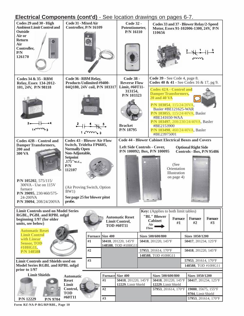
Electrical Components (cont'd) - See location drawings on pages 6-7.Codes 29 and 30 - HighAmbient Limit Control andOutsideAir orReturnAirController,P/N126170
Code 31 - Mixed AirController, P/N 16109
Codes 33 and 37 - Blower Relay/2-SpeedMotor, Essex 91-102006-1300, 24V, P/N110656
Code 32 -Potentiometer,
P/N 16110
Codes 34 & 35 - RBMRelay, Essex 134-2012-101, 24V, P/N 98118
Code 36 - RBM Relay,Products Unlimited #9400-04Q180, 24V coil, P/N 103317
Code 38 -Reverse Flow
Limit, #60T11-313154,
P/N 103323Codes 42A - Control andDamper Transformers,20 and 40 VA
Code 39 - See Code 4, page 8.Codes 40 & 41 - See Codes 16 & 17, pg 9.
P/N 103054, 115/24/20VA,Basler #BE121625-WAR
P/N 103055, 115/24/40VA, Basler#BE141650-WAA
P/N 103497, 208/230/24/40VA, Basler#BE2153900
P/N 103498, 460/24/40VA, Basler#BE23975001
Codes 42B - Control andDamper Transformers,200 and300 VA
P/N 105202, 575/115/300VA - Use on 115Vfurnace
P/N 39095, 230/460/575-24-200VA
P/N 39094, 208/24/200VA
Codes 43 - Blower Air FlowSwitch, Tridelta FP6605,Normally OpenNon-Adjustable,Setpoint.175"w.c.,P/N112107
Code 44 - Blower Cabinet Electrical Boxes and Covers
Left Side Controls - Cover,P/N 100092; Box, P/N 100095
Optional Right SideControls - Box, P/N 95486
See page 25 for blower pitotprobe.
(SeeOrientationIllustrationon page 4)
Limit Controls used on Model SeriesRGBL, PGBL and RPBL mfgdbeginning 1/97 (for olderunits, see below)
"BL" BlowerCabinetAir
Flow
Furnace#1
Furnace#2
Furnace#3
Automatic ResetLimit Controlwith LinearSensor, TOD#10HG11,P/N 148588
Automatic ResetLimit Control,TOD #60T11
Limit Controls and Shields used onModel Series RGBL and RPBL mfgdprior to 1/97
AutomaticResetLimitControl,TOD#60T11
Furnace Size 400 Sizes 500/600/800 Sizes 1050/1200#1 50418, 201220, 145°F 50418, 201220, 145°F 50417, 201234, 125°F
148588, TOD #10HG11#2 57953, 201614, 170°F 50418, 201220, 145°F
148588, TOD #10HG11#3 57953, 201614, 170°F
148588, TOD #10HG11
Furnace Size 400 Sizes 500/600/800 Sizes 1050/1200#1 50418, 201220, 145°F 50418, 201220, 145°F 50417, 201234, 125°F
12229, Limit Shield 12229, Limit Shield#2 57953, 201614, 170°F 19080, 35675, 155°F
9704, Limit Shield#3 57953, 201614, 170°FP/N 12229 P/N 9704
Limit Shields
Key: (Applies to both limit tables)

Form RZ-NA-P-RG/RP/RBL, Page 11
Code P/N Component Description1N 61145 Natural gas pilot with orifice, high tension lead, flame
probe (less pilot tubing and flame sensor lead)1P 61146 Propane gas pilot with orifice, high tension lead, flame
probe (less pilot tubing and flame sensor lead)2N 63088 Natural gas pilot orifice only (7221)2P 37801 Propane gas pilot orifice only (4209)3 5145 Pilot tubing, 22" long
9664 Nut with breakaway ferrules (2 required)4 44675 Sensor lead 9" long5* 112647 Crimp-on, 90° Rajah terminal connector6* 112648 90° Boot Terminal Protector
1N,1P
2N, 2P
4
5*
6*
3
Replacement Pilot -All Furnaces
Toggle SwitchesP/N 40277, DPDT,3-Position ToggleSwitch in a4x4 box(SameasOptionCN1)
P/N 101900, DPDT, 3-PositionToggle Switch (replaces P/N 21826) -Used in OptionCN1 and RemoteConsole OptionsRC5, RC6,RC7, RC8,RC10, RC11,RC12
P/N 39732, DPST,2-Position ToggleSwitchin a 2x4box (Sameas OptionCN2)
P/N 101902, DPST,2-Position ToggleSwitch (replaces P/N16816) - Used inOptions CN2, AG3,AG8, AG9 andRemote ConsoleOption RC12
P/N 39733, SPDT,2-Position ToggleSwitch ina 2x4 box(Same asOptionCN3)
P/N 39748, SPST, 2-Position Toggle Switch in a 2x4 box(Same as Option CN4)
NOTE: When replacing SPSTswitch with SPDT switch, makewiring connections at appropriatetwo terminals for switch to func-tion properly.
P/N 101901, DPST,2-Position Toggle Switch (replacesP/N 1052) - Used in Options CN3,CN4, and Remote ConsoleOptions RC3,RC4, RC7,RC8, RC11
*Included in the replacementkit which covers several models of heaters; these parts are not usedwhen replacing pilots on the heaters covered in this manual.
ReplacementPilot Kits:Natural Gas -P/N 110861Propane Gas -P/N 110862
Electrical Components and Sensors when the system is equipped with a specially programmedJohnson Control Metasys® Unit for Direct Digital Control interface with the building's computerizedenvironmental control system (Options D1, D2, D3, or D4)
Johnson ControlsMetasys®
directdigital
controlunit
Blower CabinetDDC Control Option for RGB/RPB only D1 D2 D3 D4Maintains constant mixed entering air temperature X - X -Maintains constant discharge air temperature - X - XModulating Dampers X - X -On/Off Dampers - X - XModulating Gas Control X X - -Two-Stage Gas Control - - X XFirestat (see Code 4, page 8) X X X XFreezestat (see Code 2, page 8) X X X XAir Proving Switch (see Code 43, page 10) X X X X
Component Description D1 D2 D3 D4J/C Metasys® DDC Interface Unit, 171138 171139 171140 171141#AS-UNT121-1- D1 D2 D3 D4EMI Filter, Corcom #3VK1 171738 171738 171738 171738RBM Relay (See Code 36), page 10 (2)103317 (2)103317 (3)103317 (3)103317Fuse, 2.5 amp 61542 61542 61542 61542Fuseholder, Buss HTB-481 60241 60241 60241 60241Duct Probe Temperature Sensor, 171135 171135 171135 171135J/C #TE-631 1P-1Remote Setpoint Selector, 175646 175646 175646 175646J/C #TE-6411S-2010Outdoor Temperature Sensor, J/C #TE-631 3P-1 171137 171137 171137 171137SPDT Switch in 2x4 Box (see above) (2)39733 (2)39733 (2)39733 (2)39733DDC Damper Interface Module, 171134 -- 171134 --H/W Q7230A (see Code 393, pg 27)DDC Gas Control Interface Module, 134170 134170 -- --Maxitrol SC10C-B6S1 (see photo right)
DDC Gas Control InterfaceModule in Options DG1 andDG2, P/N 134170, MaxitrolSC10C-B6S1

Form RZ-NA-P-RG/RP/RBL, Page 12
Codes 56 and 81 - Flue RestrictorsP/N Type Size P/N Type Size P/N Type Size P/N Type Size
14935 S 7-3/4 x 7-3/4 86465 S 8-1/4 x 8-1/4 86496 S 4-3/4 x 4-3/4 89213 S 8-5/8 x 8-5/815584 S 6-7/16 x 6-7/16 86479 S 1-3/4 x 5-3/4 86497 D 7-3/8 x 7-3/8 136738 D 3-3/8 x 3-3/815599 D 7-1/2 x 7-1/2 86485 D 6-1/4 x 6-1/4 86498 S 9 x 9 136740 D 5-1/8 x 5-1/815601 S 9-1/4 x 9-1/4 86488 S 8 x 8 89205 D 5-3/4 x 5-3/4 136741 D 4-13/16 x 4-13/1686435 S 4-1/8 x 4-1/8 86490 S 4-7/8 x 11-3/4 89206 S 3-5/8 x 7-1/2 136742 D 4-1/2 x 4-1/286440 D 5-5/8 x 5-5/8 86491 S 4-7/16 x 4-7/16 89208 D 6-7/8 x 6-7/8 136743 D 4-5/8 x 4-5/886444 S 3-1/2 x 7-1/2 86492 S 4-1/4 x 4-1/4 89209 D 6-3/8 x 6-3/8 136744 D 4-1/4 x 4-1/486446 S 2-3/4 x 7-1/2 86493 D 6 x 6 89210 S 3 x 7-1/2 136745 D 6-3/8 x 6-3/886454 D 7 x 7 86494 S 8-7/8 x 8-7/8 89211 S 4-3/4 x 4-7/16 136746 D 6-1/8 x 6-1/886456 D 6-5/8 x 6-5/8 86495 S 8-1/2 x 8-1/2 89212 D 7-3/4 x 7-3/4 136747 D 9-1/8 x 9-1/8
RG Exterior and Flue Box Parts - Same parts apply to RG duct furnaces in packaged ModelSeries RGB and Series RGBL (Quantites listed are per furnace section.)
Flue Restrictors -Codes 56 and 81See table, bottom ofthe page, for type andsizes.
Type S
Type D
Flue Collection Box for Basic ModelRG Furnace
Basic Exterior Parts for Model RG
Code 73 - VentCap Extension
��
72
6362
63B,C,D
6868B,C
75 60
57
67
61
58
��
��
��
��
Furnace ExtensionModel Sizes Series Height P/N
RG, HRG
300, 350, 400
Prior to Series 8 & Series 8
12" 20524
350Prior to Series 8 &
Series 8 12" 20524
400 Prior to Series 8 7-1/4" 12018400 Series 8 12" 20524
CRG, HCRG
Connector and Filler Parts for Multiple Furnace Model RGBLRGBL Size 400 500/600 700 800 1050 1200Top Filler --Side Filler --Top & Btm Duct Connector -- (2)106338 (2)106339 (2)106340 (2)106339 (2)106340Side Duct Connector -- (2)106395 (4)106395
(1)105631 (2)105631(2)105632 (4)105632
� Label, P/N 196689
Gray Sealant (3M 900 Duct SealerFast Bond), P/N 100117
77

Form RZ-NA-P-RG/RP/RBL, Page 13
500 600700, 1050
400, 800, 1200
75 100 125 150 175 200 225 250 300 350 40051 Flue Collection RG, HRG - All 1 136749 136750 86437 136751 136752 136753 136754 136755 136756 136757 86470
Box Assy CRG, HCRG - All 1 86476 86478 86480 -- 86482 -- 89207 86484 86486 86487 8648952 Collection Box Side Gasket Strip 253 Collection Box Front and Rear Gasket Strip 2 62922 62930 6293255 Flue Collar Assy 156 RG, HRG prior to
Series 81 86435 -- 86440 86444 86446 86454 86456 86444 86465 15599 --
RG, HRG Series 8 1 136738 136739 86440 136740 136741 86493 136742 86493 86454 -- --CRG, HCRG - All 1 86492 86479 89205 -- 89206 -- 89208 89209 89210 86488 86490
57 2 100037 100041 100042
58 Heater Bottom Pan Aluminized 1 100004 100005409 Stainless 1 104925 104926 104925 104929 104930
60 Heater Mounting Rail 261 2 100030 100034 100035
62 Casing Top Assy (include insulation) 1 103653 103656 *103657 103658 10365963 1
63A Heater Left Side Panel 163B Left Side Combustion Air Inlet Screen 1 -- -- -- 14839663C Left and Right Side Combustion Air Inlet Shield 163D Left and Right Side Combustion Air Inlet Angle 167 1
67A Heater Right Side Panel 167B Right Side Combustion Air Inlet Screen 1 -- -- --67C Heater Right Side Panel Handle 168 Heater Bottom Left Side Assy Natural 1
(includes Codes 68A& B or C) Gas68A Heater Bottom Left Side Panel 168B Vinyl Grommet #1020-K, 1/2" 1 -- -- --68C Vinyl Grommet #1020, 3/4" 1 -- -- -- -- -- -- -- --71 Heater Bottom Left Side Assy Propane
(includes Codes 68A&B) Gas72 Vent Cap 1 *6187573 Vent Cap Extension See Table at the bottom of page 12.74 Left Rear Heater Leg 175 Left Front Heater Leg 176 Right Rear Heater Leg 177 Right Front Heater Leg 178 Baffle 179 Top Seal Brace 2 100163 100167 10016880 Hanger Angle 281 RG, HRG prior to
Series 81 86491 86492 15584 86485 86493 86488 14935 15599 15601 86494 86495
RG, HRG Series 8 1 136743 136744 136745 136746 86493 89212 15596 86454 136747 86495 86495CRG, HCRG - All 1 86496 89211 15584 -- 86485 -- 86488 89212 86497 86498 89213
*Model CRG300 - Casing Top Assembly, P/N 103656; Vent Cap (10"), P/N 61866
Qty
Bottom Front & Rear Panel (Sizes 75-100 include insulation)
Flue Restrictor - See Type and Size at the bottom of page 12.
"Z" Baffle used with optional extended stack (Option ZZ) - See Type & Size on bottom of pg 12.
Heater Right Side Panel Assy (includes Codes 67A-C,63C-D)
Top Front and Rear Panel (Sizes 75-100 include insulation)
11012
61875, 12"
Heater Upper Left Side Panel Assy (includes Codes 63A, 63B, 63C, & 63D)
10921100162 100164 100165 100166
100008 100012100006 100010
100009 100013100007 100011
10260715021
110053, 6" 61857, 8" 61866, 10"
100112100298 100299
100125
103648 103649
100111148396
10011610800
11069712649 10850
103652 103654 103655
103646 103647
103645 100031 100032 100033
104926 104927 104928100126
100000 100001 100002 100003
103788 12014 12015
103644 100038 100039 100040
DescriptionCode
1 100298
6293362921 62924 62926 62928103786
Form RZ-NA-P-RG/RP/RBL, Page 14
5:����'� ����##$$5�
5:0��3������ �
�/ �������*����/� � �3��!�����0�0�+ ��*#��:�#��:��$��/��3
.��6#3��7
5:0��3<$?�(�2
#;:6.5���7*������� � �
,8��0� ����**+����#$=$�5���0
�����������.=..%
'��(/*�������4���"�
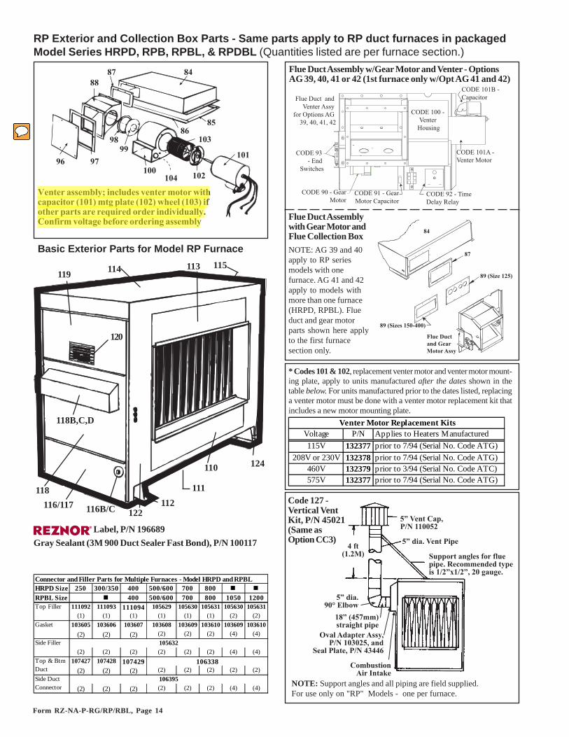
Code 127 -Vertical VentKit, P/N 45021(Same asOption CC3)
RP Exterior and Collection Box Parts - Same parts apply to RP duct furnaces in packagedModel Series HRPD, RPB, RPBL, & RPDBL (Quantities listed are per furnace section.)
� Label, P/N 196689Gray Sealant (3M 900 Duct Sealer Fast Bond), P/N 100117
Basic Exterior Parts for Model RP Furnace
114119
120
118112
111
110 124
115113
118B,C,D
116/117122116B/C
NOTE: Support angles and all piping are field supplied.For use only on "RP" Models - one per furnace.
;;;�
<%#$#
#$.#$$
<<<;
<�
;.
;5;%
#$=
#$�
Venter assembly; includes venter motor with capacitor (101) mtg plate (102) wheel (103) if other parts are required order individually. Confirm voltage before ordering assembly
* Codes 101 & 102, replacement venter motor and venter motor mount-ing plate, apply to units manufactured after the dates shown in thetable below. For units manufactured prior to the dates listed, replacinga venter motor must be done with a venter motor replacement kit thatincludes a new motor mounting plate.
CODE 100 - Venter
Housing
CODE 101A - Venter Motor
CODE 92 - Time Delay Relay
CODE 90 - GearMotor
CODE 93 - End
Switches
Flue Duct and Venter Assy
for Options AG 39, 40, 41, 42
CODE 101B - Capacitor
CODE 91 - GearMotor Capacitor
Flue Duct Assembly w/Gear Motor and Venter - OptionsAG 39, 40, 41 or 42 (1st furnace only w/Opt AG 41 and 42)
HRPD Size 250 300/350 400 500/600 700 800RPBL Size 400 500/600 700 800 1050 1200Top Filler 111092 111093 111094 105629 105630 105631 105630 105631
(1) (1) (1) (1) (1) (1) (2) (2)Gasket 103605 103606 103607 103608 103609 103610 103609 103610
(2) (2) (2) (2) (2) (2) (4) (4)Side Filler
(2) (2) (2) (2) (2) (2) (4) (4)107427 107428 107429
(2) (2) (2) (2) (2) (2) (2) (2)
(2) (2) (2) (2) (2) (2) (4) (4)
Connector and Filler Parts for Multiple Furnaces - Model HRPD and RPBL
106395
105632
106338Top & Btm Duct Side Duct Connector
Venter Motor Replacement Kits Voltage P/N Applies to Heaters Manufactured115V 132377 prior to 7/94 (Serial No. Code ATG)
208V or 230V 132378 prior to 7/94 (Serial No. Code ATG)460V 132379 prior to 3/94 (Serial No. Code ATC)575V 132377 prior to 7/94 (Serial No. Code ATG)
84
87
89 (Size 125)
Flue Ductand GearMotor Assy
89 (Sizes 150-400)
Flue Duct Assemblywith Gear Motor andFlue Collection BoxNOTE: AG 39 and 40apply to RP seriesmodels with onefurnace. AG 41 and 42apply to models withmore than one furnace(HRPD, RPBL). Flueduct and gear motorparts shown here applyto the first furnacesection only.

Form RZ-NA-P-RG/RP/RBL, Page 15
Model RPDBL Sizes 1000 1200 1400 800, 1600
Model RPBL Sizes 500 600 700, 1050
400, 800, 1200
Model HRPD Sizes 250 300 350 400 500 600 700 800
Model (C)(H)(HC)RP(B) Sizes 125 150 175 200 225 250 300 350 40084 Flue Collection RP, HRP prior to Series 8 1 92794 92798 88348
Box Assembly RP, HRP Series 8 1 88353 92798 88348CRP, HCRP - All (no Series 8) 1 88353 -- 88357 -- -- -- 88348
85 Collection Box Side Gasket Strip 286 Collection Box Front and Rear Gasket Strip 2 62922 62930 6293287 Flue Duct Gasket 188 Flue Duct Assembly All except w/Opt AG 39 & 40 and
1st furnace w/Opt AG 41 & 421
89 Flue Duct Restrictor 1 17481790 Gear Motor 1 20614491 Gear Motor Capacitor, 15MFD 1 20614592 Time Delay Relay 2 20614693 Safety End Switch All AG39, AG40, AG41 & AG42 2 17481294 1 208475
95 1 1748471 1748461 174814
96 Flue Duct Cover Plate 197 Cover Plate Gasket 198 Venter Gasket 1
Venter Restrictor Models RP, HRP 1 43254 43255 43256 43257 43258 43259 43260 43261 --Models CRP, HCRP 1 88506 -- 68382 -- -- 68386 88507 -- 88508
Series 8 w/Opt AG 39, 40, 41, 42 1 68388 68386 68390 43260 175787 43260 --* --*100 Venter Housing 1 92792
101A *Venter Motor 115V 1208V 1230V 1460V 1575V 1
101B Venter Motor Capacitor 1101C Capacitor Boot, Syntex #M-78 1102 *Venter Motor Mounting Model RP, HRP 1 131448
Plate Assembly Model CRP, HCRP 1 131446103 Venter Wheel 1 43814104 Sensing Tube 1
RGD0015
113 Top Front and Rear Panel (Sizes 125-175 include insulation) 2 100295 100034 100035114 Casing Top Assembly (includes insulation) 1 100288 100292 100293115 Heater Right Side Panel Assembly (includes Codes 115A&B) 1
115A Heater Right Side Panel 1115B Heater Right Side Panel Handle 1
174812
For RP Series units with Option AG39 or AG40 & 1st furnace with Option AG41 or AG42
manufactured beginning 11/03
174814 (115V)
* Model/Size combinations have aninlet ring instead of a restrictor.
Replacement Solenoid Actuator only (select by voltage - same apply to Sizes 400/800/1200)
(Kit to replace the solenoid valve actuator with a gear motor actuator.)Replacement Gear Motor Kit (to replace solenoid actuator)
419954199644695
208474For RP Series units with Option AG39 or AG40 & 1st furnace with Option AG41 or AG42
manufactured prior to 11/03
174847 (460V)174846 (208/230V)
99
92795
31900
41991
206145
62928
92796 9279788357 136748 88359
206146
8835962933
62924 62926
206144174818
Cod
e Description (If special application is not listed, part applies to all Model RP Series Units.)
Qty
(per
furn
ace)
92778163891163892163892163893163891163894103182
13144513144543425
171750
100296 100032 100033100289 100290 100291
100294100118100112
(If unit was mfgd before 7/94, do notorder motor or motor mounting plate (CODE 102). See list of replacementkits on page 14.)
116 Heater Btm Left Side Assy Nat Gas (includes 116A & B or C) 1116A Heater Btm Left Side Panel 1116B Vinyl Grommet #1020-K, 1/2" 1 -- -- --116C Vinyl Grommet #1020, 3/4" 1 -- -- -- -- -- --117 Heater Btm Left Side Assy Propane (includes Codes 116A&B) 1118 Heater Center Left Side Panel Assembly (includes Codes 118A-D) 1 103660
118A Heater Center Left Side panel (panel only) 1118B Combustion Air Inlet Screen 1118C Combustion Air Inlet Shield 1118D Combustion Air Inlet Angle 1119 Heater Top Left Side Panel 1120 Grill Assembly 1121 Left Rear Heater Leg 1122 Left Front Heater Leg 1123 Right Rear Heater Leg 1124 Right Front Heater Leg 1125 Hanger Angle 2126 Top Seal Brace 2 100163 100167 100168127 Vertical Vent Kit, P/N 45021 - See illustration, page 14.
100298 100299
148396110697
100125102607
15021100298
10001110001210001011012
100164 100165
1085010011541992
100013
100318100297
100166
115v venter assembly 105
105B 208/230v venter assembly
105C 460v Venter assembly
RGD0013
RGD0016 RGD0016 RGD0016 RGD0016 RGD0016 RGD0017
RGD0014 RGD0014 RGD0014 RGD0014 RGD0014
RGD0012 RGD0012RGD0012 RGD0012 RGD0012

Form RZ-NA-P-RG/RP/RBL, Page 16
PGBL FurnaceCabinet andVenter Box Parts
Indoor Model PGBL800with two furnace sectionsand a "BL" blower cabinet
Venter Box (Codes 128-132)Venter Components (Codes 136-142)
149
148
155
150151 153
146
145
156
Code Description 400 800 1200128 Venter Box Bottom 150971 149851 149852129 Venter Box Cover 149853 149854 149855130 Venter Cover End 150974 149856 149856131 Venter Gasket --132 Venter Baffle --133 Flow Sensing Probe134 Sensor Bracket135 Silicone Tubing, Red 17"- 151564136 Venter Housing 151560137 Venter Motor 115V/1Ph 87434 Fasco #7162-1775
208V/1Ph 30249 Fasco #7162-0186230V/1Ph 29571 Fasco #7162-0158208V/3Ph 30249 Fasco #7162-0186230V/3Ph 29571 Fasco #7162-0158460V/3Ph 87434 Fasco #7162-1775575V/3Ph 87434 Fasco #7162-1775
138 Capacitor, Ronken 4MFD 370V139 Venter Wheel 29792 Torrington #AA408228, 1-5/16"140 Venter Fan, PM Motor Type 3141 Venter Junction Box142 Venter Junction Box Cover
149857150973
151559123910
9"- 147905
16074 A. O. Smith Cat #19916074 A. O. Smith Cat #19916074 A. O. Smith Cat #199
151343
16075 Century 8-12543916075 Century 8-12543916075 Century 8-125439
16074 A. O. Smith Cat #199
29596
1638948735 Torrington #AA729-419-7-29/32-4-17/322979329595
Code Description 400 800 1200 Code Description 400 800 1200143 149859 (2)149859 (3)149859 150A Heater Left Side Panel 100116 (2)100116 (3)100116
144 Flue Collar Assy (interior) 150326 (2)150326 (3)150326 150B Cmbstn Air Inlet Screen 148396 (2)148396 (3)148396145 Bottom Front & Rear Panel (2)100042 (4)100042 (6)100042 150C Cmbstn Air Inlet Shield 110697 (2)110697 (3)110697146 Furnace Aluminized 100005 (2)100005 (3)100005 150D Cmbstn Air Inlet Angle 10850 (2)10850 (3)10850
Bottom Pan 409 Stainless 104930 (2)104930 (2)104930 151 Bottom Left Side Panel 100299 (2)100299 (3)100299147 Heater Mounting Rail (2)100126 (4)100126 (6)100126 152 Left Rear Heater Leg 100013 (2)100013 (3)100013148 100050 (2)100050 (3)100050 153 Left Front Heater Leg 100011 (2)100011 (3)100011
149 103649 (2)103649 (3)103649 154 Right Rear Heater Leg 100012 (2)100012 (3)100012149A Heater Right Side Panel 100111 (2)100111 (3)100111 155 Right Front Heater Leg 100010 (2)100010 (3)100010149B Right Side Panel Handle 100112 (2)100112 (3)100112 156 Top Front & Top Rear (2)100035 (4)100035 (6)100035149C Combustion Air Inlet Screen 148396 (2)148396 (3)148396 157 Baffle 10921 (2)10921 (3)10921149D Combustion Air Inlet Shield 110697 (2)110697 (3)110697 158 Top Seal Brace (2)100168 (4)100168 (6)100168149E Combustion Air Inlet Angle 10850 (2)10850 (3)10850 159A Top/Btm Ht Exch Cnntcr -- (2)106340 (4)106340150 103647 (2)103647 (3)103647 159B Side Heat Exch Connector -- (2)106395 (4)106395
Casing Top Assy (includes insulation)Right Side Panel Assy
Heater Left Side Assy
Flue Collection Box Assy (interior)
Form RZ-NA-P-RG/RP/RBL, Page 17
�������
���
���
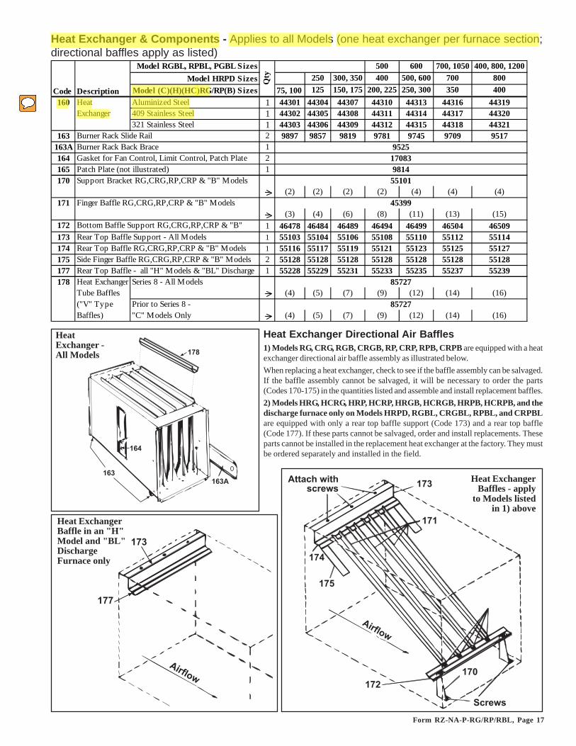
Heat Exchanger & Components - Applies to all Models (one heat exchanger per furnace section;directional baffles apply as listed)
���
��������������� ���
���
����
���
���
��!
���" �
Heat Exchanger Directional Air Baffles1) Models RG, CRG, RGB, CRGB, RP, CRP, RPB, CRPB are equipped with a heatexchanger directional air baffle assembly as illustrated below.When replacing a heat exchanger, check to see if the baffle assembly can be salvaged.If the baffle assembly cannot be salvaged, it will be necessary to order the parts(Codes 170-175) in the quantities listed and assemble and install replacement baffles.2) Models HRG, HCRG, HRP, HCRP, HRGB, HCRGB, HRPB, HCRPB, and thedischarge furnace only on Models HRPD, RGBL, CRGBL, RPBL, and CRPBLare equipped with only a rear top baffle support (Code 173) and a rear top baffle(Code 177). If these parts cannot be salvaged, order and install replacements. Theseparts cannot be installed in the replacement heat exchanger at the factory. They mustbe ordered separately and installed in the field.
HeatExchanger -All Models
���
���
���" �
Heat ExchangerBaffle in an "H"Model and "BL"DischargeFurnace only
Heat ExchangerBaffles - apply
to Models listedin 1) above
Model RGBL, RPBL, PGBL Sizes 500 600 700, 1050 400, 800, 1200Model HRPD Sizes 250 300, 350 400 500, 600 700 800
Model (C)(H)(HC)RG/RP(B) Sizes 75, 100 125 150, 175 200, 225 250, 300 350 400160 Heat Aluminized Steel 1 44301 44304 44307 44310 44313 44316 44319
Exchanger 409 Stainless Steel 1 44302 44305 44308 44311 44314 44317 44320321 Stainless Steel 1 44303 44306 44309 44312 44315 44318 44321
163 Burner Rack Slide Rail 2 9897 9857 9819 9781 9745 9709 9517163A Burner Rack Back Brace 1164 Gasket for Fan Control, Limit Control, Patch Plate 2165 Patch Plate (not illustrated) 1170 Support Bracket RG,CRG,RP,CRP & "B" Models
(2) (2) (2) (2) (4) (4) (4)171 Finger Baffle RG,CRG,RP,CRP & "B" Models
(3) (4) (6) (8) (11) (13) (15)172 1 46478 46484 46489 46494 46499 46504 46509173 Rear Top Baffle Support - All Models 1 55103 55104 55106 55108 55110 55112 55114174 Rear Top Baffle RG,CRG,RP,CRP & "B" Models 1 55116 55117 55119 55121 55123 55125 55127175 Side Finger Baffle RG,CRG,RP,CRP & "B" Models 2 55128 55128 55128 55128 55128 55128 55128177 Rear Top Baffle - all "H" Models & "BL" Discharge 1 55228 55229 55231 55233 55235 55237 55239178 Series 8 - All Models
(4) (5) (7) (9) (12) (14) (16)Prior to Series 8 - "C" Models Only (4) (5) (7) (9) (12) (14) (16)
Code Description
Qty
85727
85727
Bottom Baffle Support RG,CRG,RP,CRP & "B"
9525170839814
55101
45399
Heat Exchanger Tube Baffles("V" Type Baffles)
Form RZ-NA-P-RG/RP/RBL, Page 18
201A
201B
Carryover Tubing -Natural Gas
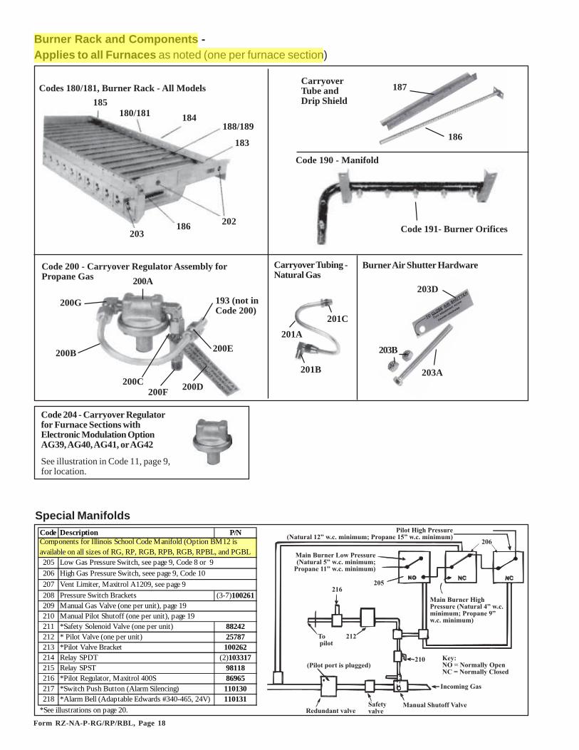
Codes 180/181, Burner Rack - All Models
Burner Rack and Components -Applies to all Furnaces as noted (one per furnace section)
201C
Code 200 - Carryover Regulator Assembly forPropane Gas 200A
200B
200C 200D
200E
200F
200G 193 (not inCode 200)
185180/181 184
183
202186203
188/189
203A
203B
203D
CarryoverTube andDrip Shield
187
186
Code 191- Burner Orifices
Code 190 - Manifold
Burner Air Shutter Hardware
Special Manifolds����1������**/��
6���/��#�:23!3�����/�@��� ���#5:23!3�����/�7�$%
�$5
���� /������2���**/��6���/��5:23!3�����/�@��� ���##:23!3�����/�7
�#%
�#�A� ���
�#$
4�!�����)�*
���/���/������8������+8�8�
6���� ����* /���07
��0/�0���8�8�
B�+C�,D�����+, ���'D�����+'�*�0
���� /����1������**/��6���/��.:23!3�����/�@��� ���<:23!3�����/�7
Code Description P/N
205206207208 Pressure Switch Brackets (3-7)100261209 Manual Gas Valve (one per unit), page 19210 Manual Pilot Shutoff (one per unit), page 19211 *Safety Solenoid Valve (one per unit) 88242212 * Pilot Valve (one per unit) 25787213 *Pilot Valve Bracket 100262214 Relay SPDT (2)103317215 Relay SPST 98118216 *Pilot Regulator, Maxitrol 400S 86965217 *Switch Push Button (Alarm Silencing) 110130218 *Alarm Bell (Adaptable Edwards #340-465, 24V) 110131
*See illustrations on page 20.
Components for Illinois School Code Manifold (Option BM12 is available on all sizes of RG, RP, RGB, RPB, RGB, RPBL, and PGBL
Low Gas Pressure Switch, see page 9, Code 8 or 9High Gas Pressure Switch, seee page 9, Code 10Vent Limiter, Maxitrol A1209, see page 9
Code 204 - Carryover Regulatorfor Furnace Sections withElectronic Modulation OptionAG39, AG40, AG41, or AG42
See illustration in Code 11, page 9,for location.

Form RZ-NA-P-RG/RP/RBL, Page 19
Main Burner Orifice - Drill Size to P/NSize 41 42 43 44 45 55 1.20mm 1.45mm 1.50mmP/N 11792 84437 11828 11833 38678 11830 63003 61652 93410
Carryover Orifice - Drill Size to P/NSize 70 65 59 57 56 54P/N 9870 9680 10370 38274 9791 9792
1000 1200 1400 800, 1600
500 600 700, 1050400, 800,
1200250 300 350 400 500 600 700 800
75 100 125 150 175 200 225 250 300 350 400180 Burner Rack Aluminum with Carryovers and Air Shutters 65973 65977 65978181 Burner Rack Stainless Steel with Carryovers and Air Shutters 65981 65985 65986
-- -- 92813 92814 92814 92815 92815 92816 92816 92818
182 Flash Carryover (one piece) 63138 -- -- -- -- -- --183 Flash Carryover Right Section -- -- -- -- -- 63148 63152184 Flash Carryover Center Section -- -- -- -- -- -- --185 Flash Carryover Left Section -- -- -- -- --186 Carryover Lighter Tube (Tube only) 9859 9711 9520187 Carryover Lighter Tube Drip Shield 15014 15010 14957188 M ain Burner Tube - Aluminized
Qty per burner assembly (4) (4) (5) (7) (7) (9) (9) (12) (12) (14) (16)189 M ain Burner Tube - Stainless Steel
Qty per burner assembly (4) (4) (5) (7) (7) (9) (9) (12) (12) (14) (16)190 M anifold (less orifices) 86339 86344 86345191 Burner (H)RG; PGBL Natural Gas All Series 45 41 41 43 41 43 41 44 41 41 41
Orifice (H)CRG Natural Gas All Series 45 43 43 -- 43 -- 43 45 43 43 43Drill Size (H)RP Natural Gas Prior to Series 8 -- -- 42 44 42 43 42 44 42 42 42
Series 8 -- -- 42 44 42 43 42 44 42 42 42See (H)CRP Natural Gas Prior to Series 8 -- -- 43 -- 43 -- -- 45 43 -- 43table below (H)RG; PGBL Propane Gas All Series 1.20mm 1.45mm 1.45mm 55 1.45mm 55 1.45mm 55 1.45mm 1.45mm 1.45mmfor P/N's. (H)CRG Propane Gas All Series 1.20mm 55 55 -- 55 55 55 1.20mm 55 55 55
(H)RP Propane Gas Prior to Series 8 -- -- 1.45mm 55 1.45mm 55 1.45mm 55 1.45mm 1.50mm 1.45mmSeries 8 -- -- 1.45mm 55 1.45mm 55 1.45mm 55 1.45mm 1.50mm 1.45mm
(H)CRP Propane Gas Prior to Series 8 -- -- 55 -- 55 -- -- 1.20mm 55 -- 55193 Carryover (H)RG Natural Gas All Series 70 70 70 65 65 59 59 59 59 54 54
Orifice (H)CRG Natural Gas All Series 70 70 70 -- 65 -- 59 59 59 54 54Drill Size (H)RP Natural Gas Prior to Series 8 -- -- 70 65 65 65 65 59 59 57 56
Series 8 -- -- 70 65 65 65 65 59 59 57 56(H)RP Natural Gas w/AG 39, 40, 41, 42 -- -- 70 65 65 65 65 59 59 56
See (H)CRP Natural Gas Prior to Series 8 -- -- 70 -- 65 -- -- 59 59 -- 56table below (H)RG Propane Gas All Series 70 70 70 65 65 65 65 59 59 56 56for P/N's. (H)CRG Propane Gas All Series 70 70 70 -- 65 -- 65 59 59 56 56
(H)RP Propane Gas Prior to Series 8 -- -- 70 65 65 65 65 59 59 57 56Series 8 -- -- 70 65 65 65 65 59 59 57 56
(H)CRP Propane Gas Prior to Series 8 -- -- 70 -- 65 -- -- 59 59 -- 56200 Carryover Regulator Assembly (includes Codes 200A-G)
200A Carryover Regulator, Maxitrol RV-12, Propane GasCarryover Regulator, Natural Gas w/Opt AG 39, 40, 41, 42
200B Carryover Regulator Tubing 1/4" x 5-1/2"200C Carryover Regulator Tubing 1/4" x 1-1/4"200D Carryover Regulator Tag200E Carryover Regulator Fitting (Compression Fitting)200F Carryover Regulator Fitting, Regulator to Manifold200G Carryover Regulator Fitting, 90° Brass Elbow201A Carryover Tubing, Natural Gas 201B Brass Elbow201C Compression Fitting202 Burner Rack Isinglass
203A Air Shutter Adjustment Screw, 1/4-20 x 2-1/2" long203B Air Shutter Screw Nut, 1/4" -20203C Air Shutter Slide Tinnerman Nut, 1/4"-20 (not illustrated)203D Air Shutter Adjustment Instruction Tag 11934
10756 (2)10653
10650 (2)10651
18224 (2)93389933889664
118921193596641436
10071211294112949681
85218
87954
86338 86340 86342 86343
15015 15013 15012 15011
63156 6807163144
9899 9821 9783 9747
63128 6313163148 63141
65980 65982 65983 6598465972 65974 65975 65976
Replacement Burner Rack Stainless Steel with Carryovers for RP units with Gas Control Option AG 39, 40, 41 and 42
Code Description
Model RPDBL S izes
Model HRPD S izesModel (C)(H)(HC)RG/RP(B) Sizes
Model RGBL, RPBL, PGBL Sizes
Ball Valve Adapter1", P/N 110758;1-1/4", P/N 110759;1/2", P/N 120373;3/4", P/N 120169
Manual Gas Valves - All Furnaces (Reference: for electric gas valves, see Form P-VALVES)
Pilot ShutoffValve, P/N 3284 125 PSIG Gas Valve
1", P/N 159725;1-1/4", P/N 159729
Aluminum Shutoff Valves
1/2", P/N 196910,with Union,P/N 15971;3/4", P/N 196911,with Union,P/N 15972

Form RZ-NA-P-RG/RP/RBL, Page 20
Codes 211, 212, 224,240 - Solenoid Valve
Code 223 - Vent Valve,G/C #S262, P/N 86996
Code 216, 247 - PilotRegulator, MaxitrolR400S, P/N 86965
Springs for R400S Pilot RegulatorMaxitrol Pressure Approx.P/N Color Range (w.c.) LengthR400B10-13 Brown 1.0 to 3.5 1-9/16 to 2"R400B10-25 Cadmium Plate 2.0 to 5.0 1-9/16 to 2"R400B10-36 Cadmium Plate 3.0 to 6.0 1-9/16 to 2"R400B10-38 Pink 3.0 to 8.0 1-9/16 to 2"
Illinois School CodeRemote Console withAlarm Bell and SilencingButtons
P/N 86993 Actuator(M/H V4055A1007)
Valve only (used with actuator on the right)Reznor M/H
Size Gas P/N P/N1" N or P 86992 V5055A10041-1/4" N or P 89356 V5055A10122" N or P 91079 V5055A1038
Codes 219and 237
Code 213, 229,241 - PilotValve Bracketin OptionsBM12, BM13,BM14
P/N 100262
Console Box,P/N 107010Light,P/N 101889
218
217
1/4", P/N 257873/4", P/N 882421", P/N 112922
�=�
�=<
=�;
�=<
�=< ���!�A������<%;$<
Codes 237-249 - FM, Option BM14(applies to Model Series RPBL andPGBL)
��# �#<
��;
�#<
��5
��%
��% ���!�A������<%;$<
��%
�������*���/��.:��� ���<:
������ �
���!�A������<%;$<
Codes 219-236 - IRI, Option BM13 (applies to Model RPBL 1050and 1200 and Model PGBL 1200) - Not manufactured after 9/2003.
Code Description P/N Code Description P/N
219 Fluid Power Valve (2) 89356 229 Transformer 230/460 to 115V, .5KVA 86997Fluid Power Valve Actuator (2) 86993 Transformer 208 to 115V, .5KVA 86998
220 Transformer 208 to 115V, 250VA 86991221 Transformer 230/460/575 to 115V, 300VA 105202222 Vent Limiter, Maxitrol A1209, page 9 (2)123481 230 Pilot Regulator (3)86965223 Vent Solenoid Valve 86996 231 Valve Box Top 110194224 Pilot Valve (one per unit) 25787 232 Valve Box Inlet Side 110195225 Manual Shutoff & Ball Valve Adapter, page 19 233 Valve Box Plain Side 110196226 Pilot Manual Shutoff (one per unit), page 19 234 Valve Box Back 110197227 RBM Relay (4)98118 235 Top Door 110198228 Pilot Valve Bracket (2)100262 236 Bottom Door 110199
Components for IRI Manifold (Option BM13 is available on Model PGBL 1200 and RPBL 1050 and 1200) - not mfgd after 9/2003
Low Gas Pressure Switch, page 9, Code 8 or 9High Gas Pressure Switch, page 9, Code 10
Code Description P/N
237 Fluid Power Valve 89356Fluid Power Valve Actuator 86993
238 Manual Shutoff and Ball Valve Adapter, page 9239 Pilot Manual Shutoff (one per unit), page 9240 Pilot Valve (one per furnace) 25787241 Pilot Valve Bracket 100262242 Pilot Regulator 86965243 Transformer 230/460/575 to 115V, 300VA 105202
Transformer 208 to 115V, 250VA 86991244 Valve Box Top 110211245 Valve Box Inlet Side 110195246 Valve Box Plain Side 110196247 Valve Box Back 110212248 Top Door 110213249 Bottom Door 110214
Components for FM Manifold (Option BM14 is available on Model RPBL and (C)RGBL 500-1200, and PGBL 1200)
Special Manifolds (cont'd)
Form RZ-NA-P-RG/RP/RBL, Page 21
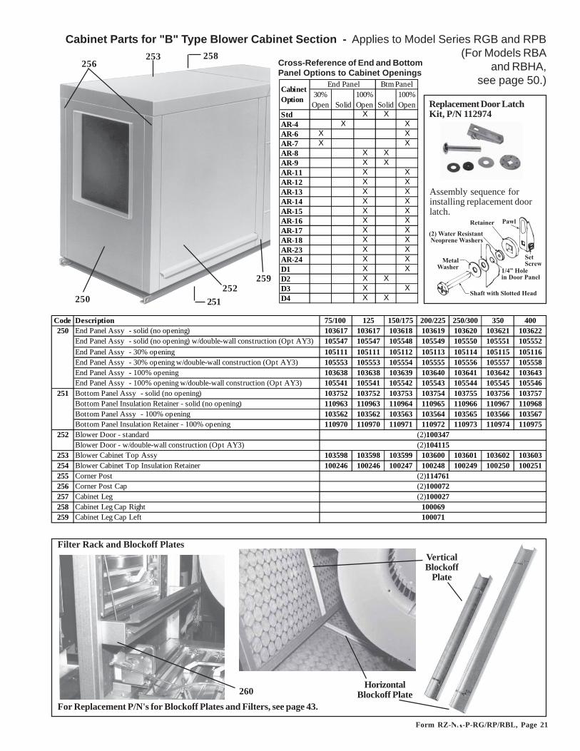
VerticalBlockoff
Plate
HorizontalBlockoff Plate260
Cabinet Parts for "B" Type Blower Cabinet Section - Applies to Model Series RGB and RPB(For Models RBA
and RBHA,see page 50.)
Filter Rack and Blockoff Plates
253256
250252
259
258
251
For Replacement P/N's for Blockoff Plates and Filters, see page 43.
Cross-Reference of End and BottomPanel Options to Cabinet Openings
6�79������*�*������� ����9�*���*
��2
����!��2
#�.:1����-�������
����9�*���
�����2��������01��0
��������
Replacement Door LatchKit, P/N 112974
Assembly sequence forinstalling replacement doorlatch.
Code Description 75/100 125 150/175 200/225 250/300 350 400250 End Panel Assy - solid (no opening) 103617 103617 103618 103619 103620 103621 103622
End Panel Assy - solid (no opening) w/double-wall construction (Opt AY3) 105547 105547 105548 105549 105550 105551 105552End Panel Assy - 30% opening 105111 105111 105112 105113 105114 105115 105116End Panel Assy - 30% opening w/double-wall construction (Opt AY3) 105553 105553 105554 105555 105556 105557 105558End Panel Assy - 100% opening 103638 103638 103639 103640 103641 103642 103643End Panel Assy - 100% opening w/double-wall construction (Opt AY3) 105541 105541 105542 105543 105544 105545 105546
251 Bottom Panel Assy - solid (no opening) 103752 103752 103753 103754 103755 103756 103757Bottom Panel Insulation Retainer - solid (no opening) 110963 110963 110964 110965 110966 110967 110968Bottom Panel Assy - 100% opening 103562 103562 103563 103564 103565 103566 103567Bottom Panel Insulation Retainer - 100% opening 110970 110970 110971 110972 110973 110974 110975
252 Blower Door - standardBlower Door - w/double-wall construction (Opt AY3)
253 Blower Cabinet Top Assy 103598 103598 103599 103600 103601 103602 103603254 Blower Cabinet Top Insulation Retainer 100246 100246 100247 100248 100249 100250 100251255 Corner Post256 Corner Post Cap257 Cabinet Leg258 Cabinet Leg Cap Right259 Cabinet Leg Cap Left 100071
(2)114761
(2)100347(2)104115
(2)100072(2)100027
100069
30% Open Solid
100% Open Solid
100% Open
Std X XAR-4 X XAR-6 X XAR-7 X XAR-8 X XAR-9 X XAR-11 X XAR-12 X XAR-13 X XAR-14 X XAR-15 X XAR-16 X XAR-17 X XAR-18 X XAR-23 X XAR-24 X XD1 X XD2 X XD3 X XD4 X X
Btm Panel End PanelCabinet Option
Form RZ-NA-P-RG/RP/RBL, Page 22
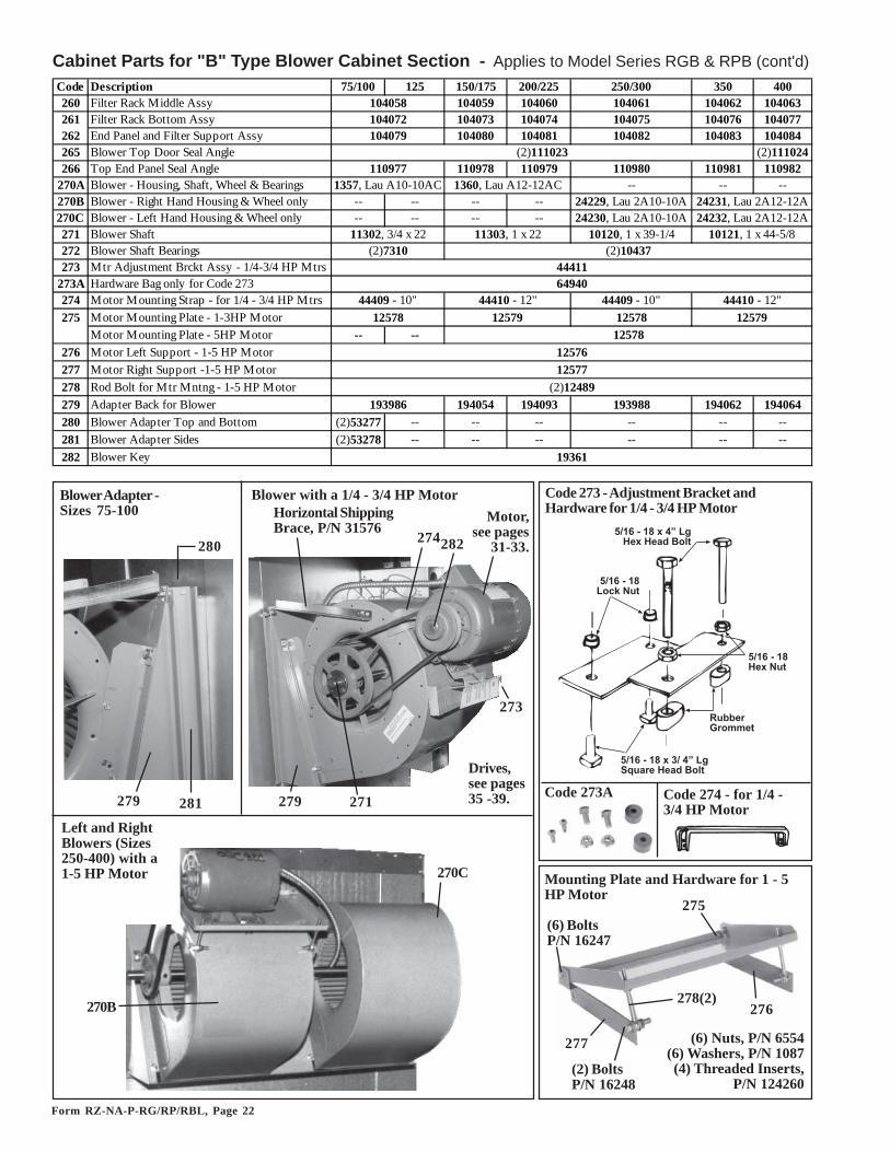
271
274282
273
279
Horizontal ShippingBrace, P/N 31576
Blower with a 1/4 - 3/4 HP Motor
280
281279
Blower Adapter -Sizes 75-100
Left and RightBlowers (Sizes250-400) with a1-5 HP Motor
270B
270C
�#���$����%��&���'�%�'���( "�
�#���$���'�%�)*�
�#���$���� �+�)*�
�*,,�- ..��
�#���$����%��#��&��� /*��'���( "�
Code 274 - for 1/4 -3/4 HP Motor
Code 273A
Code 273 - Adjustment Bracket andHardware for 1/4 - 3/4 HP MotorMotor,
see pages31-33.
Drives,see pages35 -39.
Mounting Plate and Hardware for 1 - 5HP Motor
(6) BoltsP/N 16247
(2) BoltsP/N 16248
275
277
278(2)276
(6) Nuts, P/N 6554(6) Washers, P/N 1087(4) Threaded Inserts,
P/N 124260
Cabinet Parts for "B" Type Blower Cabinet Section - Applies to Model Series RGB & RPB (cont'd)Code Description 75/100 125 150/175 200/225 250/300 350 400260 Filter Rack Middle Assy 104059 104060 104061 104062 104063261 Filter Rack Bottom Assy 104073 104074 104075 104076 104077262 End Panel and Filter Support Assy 104080 104081 104082 104083 104084265 Blower Top Door Seal Angle (2)111024266 Top End Panel Seal Angle 110978 110979 110980 110981 110982
270A Blower - Housing, Shaft, Wheel & Bearings -- -- --270B Blower - Right Hand Housing & Wheel only -- -- -- -- 24229, Lau 2A10-10A270C Blower - Left Hand Housing & Wheel only -- -- -- -- 24230, Lau 2A10-10A271 Blower Shaft 10120, 1 x 39-1/4272 Blower Shaft Bearings273 Mtr Adjustment Brckt Assy - 1/4-3/4 HP Mtrs
273A Hardware Bag only for Code 273274 Motor Mounting Strap - for 1/4 - 3/4 HP Mtrs 44409 - 10"275 Motor Mounting Plate - 1-3HP Motor 12578
Motor Mounting Plate - 5HP Motor -- --276 Motor Left Support - 1-5 HP Motor277 Motor Right Support -1-5 HP Motor278 Rod Bolt for Mtr Mntng - 1-5 HP Motor279 Adapter Back for Blower 194054 194093 193988 194062 194064280 Blower Adapter Top and Bottom (2)53277 -- -- -- -- -- --281 Blower Adapter Sides (2)53278 -- -- -- -- -- --282 Blower Key
104072104058
104079
24232, Lau 2A12-12A
(2)111023110977
(2)7310 (2)10437
1357, Lau A10-10AC 1360, Lau A12-12AC24231, Lau 2A12-12A
11302, 3/4 x 22 11303, 1 x 22 10121, 1 x 44-5/8
44409 - 10" 44410 - 12" 44410 - 12"
4441164940
12578 12579 12579
19361
193986
125781257612577
(2)12489

Form RZ-NA-P-RG/RP/RBL, Page 23
Cabinet Parts for "BL" Type Blower Cabinet Section - Applies to RGBL, RPBL and PGBL(For Model RBL cabinet parts, see page 52.) Cross-Reference of End and Bottom
Panel Options to Cabinet Openings byOption"BL"
BlowerCabinet
Code Description 500/600 700/1050 400/800 /1200300 Cabinet Btm - Right Half - solid (no opening) 106244
Cabinet Btm - Left Half - solid (no opening) 106238 106239 106240Cabinet Btm - Right Half - return air opening 105606 105607 105608Cabinet Btm - Left Half - return air opening 104365 104366 104367
301 End Panel Assy - solid (no opening) 103620 103621 103622End Pnl Assy - solid (no opening) w/double-wall cnstrctn (Opt AY3) 105550 105551 105552End Panel Assy - 30% opening 105114 105115 105116End Pnl Assy - 30% opening w/double-wall construction (Opt AY3) 105556 105557 105558End Panel Assy - 100% opening 103641 103642 103643End Pnl Assy - 100% opening w/double-wall construction (Opt AY3) 105544 105545 105546
302 Blower Door - standardBlwr Door - w/double-wall construction (Opt AY3)
303 Filter Cabinet Door AssyFilter Cabinet Assy - w/double-wall construction (Opt AY3)
106242
(2)100347(2)104115(2)106276(2)107350
Code Description 500/600 700/1050 400/800 /1200304 Blower Cabinet Front Top Section Assy 106280 106281 106282
Blower Cabinet Rear Top Section Assy 106286 106287 106288305 Blower Cabinet Top Insulation Retainer 107350 107351 107352306 Filter Cabinet Top Insulation Retainer 107354 107355 107356307 BL Cabinet Leg #1, Left308 BL Cabinet Leg #2, Right309 Corner Post 310 Cabinet Leg Cap Left311 Cabinet Leg Cap Right312 Cabinet Intermediate Post313 Cabinet Intermediate Post Cap314 Corner Post Cap315 Cabinet Top Front Panel 105610 105611 105612316 Cabinet Bottom Front Panel 105614 105615 105616317 Cabinet Vertical Blower Support Left318 Cabinet Vertical Blower Support Right319 Cabinet Horizontal Blower Support320 Cabinet and Panel Support 100078 100079 100080321 Cabinet Top Support 105600 105601 105602322 Mfgd prior to 9/91 w/std left side controls 106314 106315 106316
Mfgd prior to 9/91 w/optional right side cntrls 110016 110017 110018Mfgd beginning 9/91 - all 114711 114712 114713
323 Cabinet Rear Filter Rack Mfgd prior to 9/91 (2)106317 (2)106318 (2)106319Assy for 1 & 2" filters Mfgd beginning 9/91 (2)114707 (2)114708 (2)114709
324 Cabinet Front Filter Rack Mfgd prior to 9/91 106320 106321 106322Assy for 1 & 2" filters Mfgd beginning 9/91 (2)114695 (2)114696 (2)114697
325 Cabinet Top Filter Rack Mfgd prior to 9/91 106325 106326 106327Assy for 1 & 2" filters Mfgd beginning 9/91 114719 114720 114721
326 1" Filter Clamp -- -- (3)1062481" Filter Clamp
327 2" Filter Clamp -- -- (3)1062292" Filter Clamp
328 Top Door Seal329 BL Blower Cabinet Adapter RGBL, RPBL, RBL 163833 163834 106294
Back Assembly PGBL -- -- 148429
105603105604
(2)114761100069
Cabinet Bottom Filter Rack Assy for 1 & 2" filters
100071(2)114762(2)104372(2)100072
Apply only to units manufactured prior to 9/91
(6)106324(2)95487
106299106943
(2)31576
(6)106323
30% Open Solid
100% Open Solid
100% Open
Std X XAR-4 X XAR-6 X XAR-7 X XAR-8 X XAR-9 X XAR-11 X XAR-12 X XAR-13 X XAR-14 X XAR-15 X XAR-16 X XAR-17 X XAR-18 X XAR-23 X XAR-24 X XD1 X XD2 X XD3 X XD4 X X
Btm Panel End PanelCabinet Option
304
302303
317
316
304
329
Form RZ-NA-P-RG/RP/RBL, Page 24
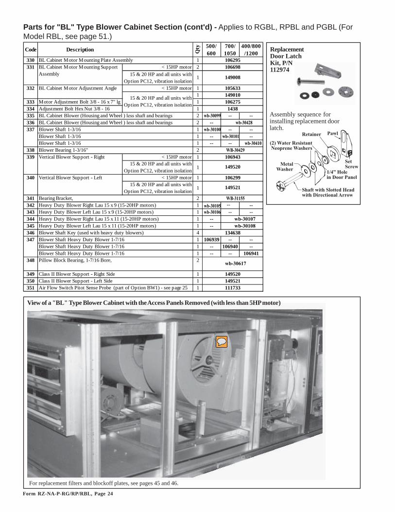
Parts for "BL" Type Blower Cabinet Section (cont'd) - Applies to RGBL, RPBL and PGBL (ForModel RBL, see page 51.)
View of a "BL" Type Blower Cabinet with the Access Panels Removed (with less than 5HP motor)
For replacement filters and blockoff plates, see pages 45 and 46.
6�79������*�*������� ����9�*���*
��2
����!��2
#�.:1����-�������
����9�*���
�����2��������01��02���-���!���������2
��������
ReplacementDoor LatchKit, P/N112974
Assembly sequence forinstalling replacement doorlatch.
Code Description Qty 500/
600700/ 1050
400/800 /1200
330 BL Cabinet Motor Mounting Plate Assembly 1331 < 15HP motor 2
15 & 20 HP and all units with Option PC12, vibration isolation
1
< 15HP motor 11
333 Motor Adjustment Bolt 3/8 - 16 x 7" lg 1334 Adjustment Bolt Hex Nut 3/8 - 16 1335 BL Cabinet Blower (Housing and Wheel ) less shaft and bearings 2 wb-30099 -- --336 BL Cabinet Blower (Housing and Wheel ) less shaft and bearings 2 --337 Blower Shaft 1-3/16 1 wb-30100 -- --
Blower Shaft 1-3/16 1 -- wb-30101 --Blower Shaft 1-3/16 1 -- -- wb-30410
338 Blower Bearing 1-3/16" 2339 Vertical Blower Support - Right < 15HP motor 1
15 & 20 HP and all units with Option PC12, vibration isolation
1
340 Vertical Blower Support - Left < 15HP motor 115 & 20 HP and all units with
Option PC12, vibration isolation1
341 Bearing Bracket, 2342 Heavy Duty Blower Right Lau 15 x 9 (15-20HP motors) 1 wb-30105 -- --343 Heavy Duty Blower Left Lau 15 x 9 (15-20HP motors) 1 wb-30106 -- --344 Heavy Duty Blower Right Lau 15 x 11 (15-20HP motors) 1 --345 Heavy Duty Blower Left Lau 15 x 11 (15-20HP motors) 1 --346 Blower Shaft Key (used with heavy duty blowers) 4347 Blower Shaft Heavy Duty Blower 1-7/16 1 106939 -- --
Blower Shaft Heavy Duty Blower 1-7/16 1 -- 106940 --Blower Shaft Heavy Duty Blower 1-7/16 1 -- -- 106941
348 2
349 Class II Blower Support - Right Side 1350 Class II Blower Support - Left Side 1351 1
149521111733
wb-30108134638
wb-30617
149520
106299
WB-31155
wb-30428
wb-30107
149521
149520
1062751438
WB-30429106943
332
106295106698
149008
105633149010
Air Flow Switch Pitot Sense Probe (part of Option BW1) - see page 25
Pillow Block Bearing, 1-7/16 Bore,
15 & 20 HP and all units with Option PC12, vibration isolation
BL Cabinet Motor Mounting Support Assembly
BL Cabinet Motor Adjustment Angle
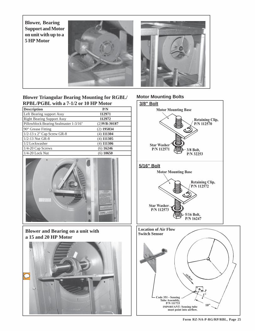
Form RZ-NA-P-RG/RP/RBL, Page 25
�������/����� �*�
�������/����� �*�
���������'� ����##�5�$
���������'� ����##�5��
����9�*������##�5�#
����9�*������##�5�=
=�; ������=��5=
5�#% ������#%�.�
Blower and Bearing on a unit witha 15 and 20 HP Motor
'�0�=5#����*���A/(��**��(+�
���###�==#$:
#:
�����2
4��,�A��AC���*����/(��/*� �������������23
Location of Air FlowSwitch Sensor
Blower Triangular Bearing Mounting for RGBL/RPBL/PGBL with a 7-1/2 or 10 HP MotorDescription P/NLeft Bearing support Assy 112971Right Bearing Support Assy 112972Pillowblock Bearing Sealmaster 1-3/16" (2)WB-3018790° Grease Fitting (2) 1958341/2-13 x 2" Cap Screw GR-8 (4) 1113041/2-13 Nut GR-8 (4) 1113051/2 Lockwasher (4) 1113061/4-20 Cap Screws (6) 162461/4-20 Lock Nut (6) 10650
Motor Mounting Bolts3/8" Bolt
5/16" Bolt
Blower, BearingSupport and Motoron unit with up to a5 HP Motor

Form RZ-NA-P-RG/RP/RBL, Page 26
Dampers and Controls - Applies to all Packaged Systems and Blower Cabinet Models RBA andRBL
Code 362 - HandQuadrant, P/N103502, (on a 30%Outside Air Damper)Code 363 - ManualDamper ControlBracket, P/N 175248
(NOTE: P/N's for Code 361 are for thedamper and frame assembly only; forlinkage and motor, see Codes 364-393.)
361
361
Model RBA
500, 600
700, 1050
400, 800, 1200, RBL
Code Description75, 100,
125150, 175
200, 225
250, 300 350 400
360 Damper and Frame Assembly only for 30% Outside Air Dampers (see illustration of 30% damper on bottom of page)
120552 120553 120554 120555 120556 120557
361 Damper and Frame Assembly only for 100% Outside Air or Return Air Dampers
105421 105422 105423 105424 105425 105426
Components by Option Description - Option AR__Code Description P/N 6 7 8 9 11 12 13 14 15 16 17 18 23362 Hand Quadrant #14004728-001 103502 X X363 Manual Damper Control Bracket (replaces P/N 103488) 143182 X X364 209351 X X X X365366 115681 X X X X X X
367 115682 X X X X X X
368 Floating Modulating Damper Motor, #M6194B1011 115683 X369 Damper Rod, 1/4 x 13 inches long 112554 X X X X X X X X370 Damper Rod, 1/4 x 18 inches long 11560 X X371 Damper Rod, 1/4 x 17 inches long 112556 X X X X X X X X372 Damper Rod, 1/4 x 22 inches long 26299 X373 Damper Rod, Bent 105420 X374 Damper Rod Arm, W-R #135-0007 66278 X377 Damper Arm, M/H #20265 12635 X(2) X X(2) X(2) X(2) X(3) X(2) X(2) X(3) X(2) X(2)378 Ball and Socket, M/H #27518 12636 X(2) X(2) X(2) X(2) X(4) X(4) X(4) X(4) X(4) X(4) X(4) X(4)380 Crank Arm M/H #221455A 116209 X X X X X X X382 Damper Arm Support Plate 14225 X383 Damper Motor Support Assy 100315 X X X X X X X X X X X384 Damper Arm Adjustment Plate 115687 X X X X X X X385 Damper Arm Adjustment Plate 142982 X386 Air Controller Support Bracket 103758 X X X X X X387 Potentiometer, M/H #112894FA 16110 X X X X388 16109 X X X X389 Outdoor Air Controller, J/C#A19AAF-120 126170 X X X390 Null Switch (pressure), Dwyer #1640 88052 X391 113963
392 145881393 171134
Replacement Kit for Damper Motor P/N 66276 (replaced by 209351 above) and P/N 97385 is P/N 209423.2-Position Damper Motor
Mixed Air Controller, M/H #T991A-1004
DDC (4-20ma) interface module for use with modulating damper motor, Honeywell Q7230A
Modulating Damper Motor, #M9175A1051 (no end switch)
Auxiliary End Switch only for M/H Damper Motors, #Q607B1067 Auxiliary Switch Kit (2 switches), M/H 220736B
Optional Modulating Damper Motor, #M9175D1014 (replacement requires auxiliary switch kit, P/N 145881)
See Damper Rigging,
pages 28 - 30.

Form RZ-NA-P-RG/RP/RBL, Page 27
Code 364 - DamperMotor for 2-PositionDamper (open/closed), J/C M9206-BGB-2S
Code 366 - Modulating DamperMotor, M/H M9175A1051 less endswitches, P/N 115681 (replaces P/N53928)Code 367 (illustrated) - ModulatingDamper Motor, M/H M9175D1014with two end switches, P/N 115682(replaces P/N 96767)
Code 368 - Modulating DamperMotor used in Option AR23,M/H #M6294B1011, P/N 115683,(with pressure null switch)
Code 391 - AuxiliaryEnd Switch,P/N 113963,M/H Q607B1067
1���E����4���-�� ��6�/�*�0����7
�����!�4���-�� ��6���/�����7
=;5 =;; =;<-�� �������
=5?
�:
<�=�.:
#�.:
���-�� ����0
Code 390 - PressureNull Switch, Dwyer#1640-0, Range.01" to .2" w.c.,P/N 88052
Damper and Control Locations
Code - 373
Damper Linkage (see pages 28-30)NOTE: Crank Arm Code 380 is used withmotors P/N 115682, 115683, and 115681(motors used in currently manufacturedunits)Use Crank Arm P/N 20874 (illustrated) ,M/H #7616BR, with motors P/N 53928,87059, and 96767
Code 387 - Potentiometer,M/H 112894FA,P/N 16110
Code 388 - Mixed AirController, M/H T991-1004, P/N 16109
Grommet Clamp,P/N 39224
Code 389 - OutsideAir Controller,J/C#A19AAF-120,P/N 126170 (replacesP/N 16108)
377
382378
374 380 (see noteon the left)
Code 393 - DDC(4-20 ma)interface modulefor modulatingdamper motor,P/N 171134,M/H Q7230A
P/N20874

Form RZ-NA-P-RG/RP/RBL, Page 28
Damper Rigging
Illustrationapplies tounits mfgdbefore Aug2004 only.
Illustrationapplies tounits mfgdbefore Aug2004 only.
Illustrationapplies tounits mfgdbefore Aug2004 only.
Illustrationapplies tounits mfgdbefore Aug2004 only.

Form RZ-NA-P-RG/RP/RBL, Page 29
Illustrationapplies tounits mfgdbefore Aug2004 only.
Illustrationapplies tounits mfgdbefore Aug2004 only.

Form RZ-NA-P-RG/RP/RBL, Page 30
Replacement Motors (Tables on pages 31-34)Motors in the Open, TEFC, and Premium Efficiency tables that are highlighted in gray do nothave internal overload protection and must be used with the motor starter and overload listed(see below). See Code 28A, page 9, for standard motor contactor for motors with internaloverloads.If equipped with an optional variable frequency drive, see P/N's on the right.
Replacement IEC Starters and Overloads (listed by motor on pages 31-34)When ordering a replacement IEC starter (contactor) or overload, check the manufacturer'snumber on both parts. If the number is different than that listed, both components must bereplaced. IEC Starter (contactor) and overload are mounted on rail, P/N 111387. Replacementholding coils are listed on page 34.
Replacement Blower Motors and Starters
IECAdjustableOverload
IEC Starter(Contactor)
Damper Rigging (cont'd)
Variable Frequency Drive(Option VFD)
HP208/3/60 (AK5) 230/3/60 (AK6)
480/3/60 (AK5)
1/2 -- 2087741 208765 208775
1-1/2 208766 2087762 208767 2087773 208768 2087785 208769 208779
7-1/2 208770 20878010 208771 20878115 208772 20878220 208773 208783
If the motor hasa NEMA starter,see the replace-ment parts onpage 35.

Form RZ-NA-P-RG/RP/RBL, Page 31
Replacement Blower Motors and StartersEff Starter (AN10) Reznor Reznor
Type HP Model No. P/N FLA volt ph % Mfr's # P/N Mfr's # min max P/NOPEN 1/4 BF2024 210611 4.6 120 1 1.35 CL00A310T-J 151146 RTA1-L 4.00 6.30 151191OPEN 1/4 BF2024 210611 2.3 208 1 1.15 63 59 CL00A310T-L 151150 RTA1-J 1.90 2.70 151189OPEN 1/4 BF2024 210611 2.3 240 1 1.15 63 59 CL00A310T-S 151147 RTA1-J 1.90 2.70 151189OPEN 1/4 H200 115864 1.1 208 3 1.35 72 74 CL00A310T-L 151150 RTA1-G 1.00 1.50 151187OPEN 1/4 H200 115864 1.4 240 3 1.35 72 74 CL00A310T-S 151147 RTA1-G 1.00 1.50 151187OPEN 1/4 H200 115864 0.75 480 3 1.35 72 81 CL00A310T-U 151148 RTA1-F 0.65 1.10 151186OPEN 1/3 BF2034 202091 6 120 1 1.35 CL00A310T-J 151146 RTA1-L 4.00 6.30 151191OPEN 1/3 BF2034 202091 3 208 1 1.35 62.8 61.3 CL00A310T-L 151150 RTA1-K 2.50 4.10 151190OPEN 1/3 BF2034 202091 3 240 1 1.35 62.8 61.3 CL00A310T-S 151147 RTA1-K 2.50 4.10 151190OPEN 1/3 H260 115863 1.4 208 3 1.35 CL00A310T-L 151150 RTA1-G 1.00 1.50 151187OPEN 1/3 H260 115863 1.6 240 3 1.35 CL00A310T-S 151147 RTA1-H 1.30 1.90 151188OPEN 1/3 H260 115863 0.8 480 3 1.35 CL00A310T-U 151148 RTA1-F 0.65 1.10 151186OPEN 1/2 BF2054 102627 8.8 120 1 1.15 CL00A310T-J 151146 RTA1-N 8.00 12.00 151193OPEN 1/2 BF2054 102627 5.1 208 1 1.15 CL00A310T-L 151150 RTA1-L 4.00 6.30 151191OPEN 1/2 BF2054 102627 4.4 240 1 1.15 CL00A310T-S 151147 RTA1-L 4.00 6.30 151191OPEN 1/2 H880 159183 2.5 208 3 1.25 CL00A310T-L 151150 RTA1-J 1.90 2.70 151189OPEN 1/2 H880 159183 3 240 3 1.25 CL00A310T-S 151147 RTA1-K 2.50 4.10 151190OPEN 1/2 H880 159183 1.5 480 3 1.25 CL00A310T-U 151148 RTA1-H 1.30 1.90 151188OPEN 1/2 AOS - H991 202089 575 3OPEN 3/4 312P629 93548 11 120 1 1.25 CL01A310T-J 151151 RTA1-P 10.00 16.00 151194OPEN 3/4 312P629 93548 6.3 208 1 1.25 CL00A310T-L 151150 RTA1-M 5.50 8.50 151192OPEN 3/4 93548 5.5 240 1 1.25 CL00A310T-S 151147 RTA1-L 4.00 6.30 151191OPEN 3/4 312P696 36951 2.9 208 3 1.25 CL00A310T-L 151150 RTA1-K 2.50 4.10 151190OPEN 3/4 312P696 36951 2.6 240 3 1.25 CL00A310T-S 151147 RTA1-K 2.50 4.10 151190OPEN 3/4 312P696 36951 1.3 480 3 1.25 CL00A310T-U 151148 RTA1-G 1.00 1.50 151187OPEN 3/4 AOS - H992 202090 575 3OPEN 1 C523 13685 13 120 1 1.25 CL01A310T-J 151151 RTA1-P 10.00 16.00 151194OPEN 1 C523 13685 7.5 208 1 1.25 CL00A310T-L 151150 RTA1-M 5.50 8.50 151192OPEN 1 C523 13685 6.5 240 1 1.25 CL00A310T-S 151147 RTA1-M 5.50 8.50 151192OPEN 1 H882 36580 3.7 208 3 1.15 79 CL00A310T-L 151150 RTA1-K 2.50 4.10 151190OPEN 1 H882 36580 3.2 240 3 1.15 79 CL00A310T-S 151147 RTA1-K 2.50 4.10 151190OPEN 1 H882 36580 1.6 480 3 1.15 79 CL00A310T-U 151148 RTA1-H 1.30 1.90 151188OPEN 1 E1006 158175 1.1 575 3 1.15 82.5 CL00A310T-Y 151149 RTA1-G 1.00 1.50 151187OPEN 1.5 C621 194202 15 120 1 1.2 86.4 77.2 CL02A310T-J 151156 RTA1-P 10.00 16.00 151194OPEN 1.5 C621 194202 7.8 208 1 1.2 86.4 77.2 CL00A310T-L 151150 RTA1-M 5.50 8.50 151192OPEN 1.5 C621 194202 7.5 240 1 1.2 86.4 77.2 CL00A310T-S 151147 RTA1-M 5.50 8.50 151192OPEN 1.5 H884 115859 5.6 208 3 1.15 66.4 78.6 CL00A310T-L 151150 RTA1-L 4.00 6.30 151191OPEN 1.5 H884 115859 5 240 3 1.15 66.4 78.6 CL00A310T-S 151147 RTA1-L 4.00 6.30 151191OPEN 1.5 H884 115859 2.8 480 3 1.15 66.4 78.6 CL00A310T-U 151148 RTA1-K 2.50 4.10 151190OPEN 1.5 E1007 158162 1.6 575 3 1.15 85.3 86.3 CL00A310T-Y 151149 RTA1-H 1.30 1.90 151188OPEN 2 V102 202581 20.4 120 1 1.15 81.8 77.5 CL25A310T-J 151160 RTA1-T 17.50 22.00 151197OPEN 2 V102 202581 10 208 1 1.15 81.8 77.5 CL01A310T-L 151155 RTA1-N 8.00 12.00 151193OPEN 2 V102 202581 10.2 240 1 1.15 81.8 77.5 CL01A310T-S 151152 RTA1-N 8.00 12.00 151193OPEN 2 H886 159327 7 208 3 1.15 67 79 CL00A310T-L 151150 RTA1-M 5.50 8.50 151192OPEN 2 H886 159327 6.6 240 3 1.15 67 79 CL00A310T-S 151147 RTA1-M 5.50 8.50 151192OPEN 2 H886 159327 3.5 480 3 1.15 67 79 CL00A310T-U 151148 RTA1-K 2.50 4.10 151190OPEN 2 E1008 158176 2.1 575 3 1.15 86 84.8 CL00A310T-Y 151149 RTA1-J 1.90 2.70 151189OPEN 3 B735 111560 14 208 1 1.15 94.5 80.3 CL02A310T-L 151159 RTA1-P 10.00 16.00 151194OPEN 3 B735 111560 12.4 240 1 1.15 94.5 80.3 CL01A310T-S 151152 RTA1-P 10.00 16.00 151194OPEN 3 H845 159185 9 208 3 1.15 CL00A310T-L 151150 RTA1-N 8.00 12.00 151193OPEN 3 H845 159185 8.6 240 3 1.15 CL00A310T-S 151147 RTA1-N 8.00 12.00 151193OPEN 3 H845 159185 4.3 480 3 1.15 CL00A310T-U 151148 RTA1-L 4.00 6.30 151191OPEN 3 H954 120019 3.6 575 3 1.15 80.3 83.8 CL00A310T-Y 151149 RTA1-K 2.50 4.10 151190OPEN 5 V211 111562 28 208 1 1.15 79.2 78.9 CL04A310M-L 151169 RTA1-V 25.00 32.00 151199OPEN 5 V211 111562 26 240 1 1.15 79.2 78.9 CL04A310M-S 151166 RTA1-V 25.00 32.00 151199OPEN 5 196033 113371 13.4 208 3 1.15 87.2 85 CL01A310T-L 151155 RTA1-P 10.00 16.00 151194OPEN 5 196033 113371 13.4 208 3 1.15 87.2 85 CL01A310T-L 151155 RTA1-P 10.00 16.00 151194OPEN 5 196033 113371 13.2 240 3 1.15 87.2 85 CL01A310T-S 151152 RTA1-P 10.00 16.00 151194OPEN 5 196033 113371 6.6 480 3 1.15 87.2 85 CL00A310T-U 151148 RTA1-M 5.50 8.50 151192OPEN 5 H956 120020 5.4 575 3 1.15 85.9 85.3 CL00A310T-Y 151149 RTA1-L 4.00 6.30 151191
Motor Starter OverloadService Factor
Power Factor

Form RZ-NA-P-RG/RP/RBL, Page 32
Replacement Blower Motors and Starters (cont'd)Eff Starter (AN10) Reznor Reznor
Type HP Model No. P/N FLA volt ph % Mfr's # P/N Mfr's # min max P/NOPEN 7.5 V305 105828 35 208 1 1.15 87 86 CL06A311M-L 151173 RTA2-E 30.00 43.00 151206OPEN 7.5 V305 105828 32 240 1 1.15 87 86 CL45A310M-S 151170 RTA1-V 25.00 32.00 151199OPEN 7.5 E302 105854 22.5 208 3 1.15 82.5 88.5 CL25A310T-L 151164 RTA1-U 21.00 26.00 151198OPEN 7.5 E300 105855 19.4 240 3 1.15 82.5 88.5 CL25A310T-S 151161 RTA1-T 17.50 22.00 151197OPEN 7.5 E300 105855 9.7 480 3 1.15 82.5 88.5 CL01A310T-U 151153 RTA1-N 8.00 12.00 151193OPEN 7.5 E324 158164 7.8 575 3 1.15 86.5 88.5 CL00A310T-Y 151149 RTA1-M 5.50 8.50 151192OPEN 10 V303 105830 42 208 1 1.15 96 84 CL06A311M-L 151173 RTA2-E 30.00 43.00 151206OPEN 10 V303 105830 38 240 1 1.15 96 84 CL06A311M-S 151172 RTA2-E 30.00 43.00 151206OPEN 10 E303 105857 31 208 3 1.15 85.5 89.5 CL04A310M-L 151169 RTA1-V 25.00 32.00 151199OPEN 10 E301 105858 26 240 3 1.15 85.5 89.5 CL04A310M-S 151166 RTA1-V 25.00 32.00 151199OPEN 10 E301 105858 13 480 3 1.15 85.5 89.5 CL01A310T-U 151153 RTA1-P 10.00 16.00 151194OPEN 10 E325 158163 10.4 575 3 1.15 81 89.5 CL01A310T-Y 151154 RTA1-P 10.00 16.00 151194OPEN 15 FM2513T-8 142287 43.1 208 3 1.15 80 87.5 CL06A311M-L 151173 RTA2-G 42.00 55.00 151202OPEN 15 FM2513T 142288 39 240 3 1.15 80 87.5 CL06A311M-S 151172 RTA2-E 30.00 43.00 151206OPEN 15 FM2513T 142288 19.5 480 3 1.15 80 87.5 CL25A310T-U 151162 RTA1-T 17.50 22.00 151197OPEN 15 FM2513T-5 142289 16 575 3 1.15 80 87.5 CL02A310T-Y 151158 RTA1-S 14.50 18.00 151196OPEN 20 FM2515T-8 142295 58.7 208 3 1.15 80 88.5 CL07A311M-L 151176 RTA2-H 54.00 65.00 151203OPEN 20 FM2515T 142296 53 240 3 1.15 81 88.5 CL07A311M-S 151175 RTA2-G 42.00 55.00 151202OPEN 20 FM2515T 142296 26.5 480 3 1.15 81 88.5 CL04A310M-U 151167 RTA1-V 25.00 32.00 151199OPEN 20 FM2515T-5 142297 21.2 575 3 1.15 80 88.5 CL25A310T-Y 151163 RTA1-T 17.50 22.00 151197TEFC 1/4 STOCK #904 105566 3.6 120 1 1 CL00A310T-J 151146 RTA1-K 2.50 4.10 151190TEFC 1/4 108152 16074 2.2 208 1 1.35 CL00A310T-L 151150 RTA1-J 1.90 2.70 151189TEFC 1/4 108152 16074 1.9 240 1 1.35 CL00A310T-S 151147 RTA1-H 1.30 1.90 151188TEFC 1/4 125439 16075 1.6 208 3 1 61.9 72.1 CL00A310T-L 151150 RTA1-H 1.30 1.90 151188TEFC 1/4 125439 16075 1.4 240 3 1 61.9 72.1 CL00A310T-S 151147 RTA1-G 1.00 1.50 151187TEFC 1/4 125439 16075 0.7 480 3 1 61.9 72.1 CL00A310T-U 151148 RTA1-F 0.65 1.10 151186TEFC 1/3 STOCK #906 115861 4.6 120 1 1 68.5 72.1 CL00A310T-J 151146 RTA1-L 4.00 6.30 151191TEFC 1/3 C151 159501 2.3 208 1 1 67.2 69.5 CL00A310T-L 151150 RTA1-J 1.90 2.70 151189TEFC 1/3 C151 159501 2.4 240 1 1 67.2 69.5 CL00A310T-S 151147 RTA1-J 1.90 2.70 151189TEFC 1/3 H261 105567 1.2 208 3 1.15 79.5 CL00A310T-L 151150 RTA1-G 1.00 1.50 151187TEFC 1/3 H261 105567 1.2 240 3 1.15 79.5 CL00A310T-S 151147 RTA1-G 1.00 1.50 151187TEFC 1/3 H261 105567 0.6 480 3 1.15 79.5 CL00A310T-U 151148 RTA1-D 0.40 0.65 151184TEFC 1/2 C613 159184 7.2 120 1 1.15 CL00A310T-J 151146 RTA1-M 5.50 8.50 151192TEFC 1/2 C613 159184 3.5 208 1 1.15 CL00A310T-L 151150 RTA1-K 2.50 4.10 151190TEFC 1/2 C613 159184 3.6 240 1 1.15 CL00A310T-S 151147 RTA1-K 2.50 4.10 151190TEFC 1/2 H274 16077 2.3 208 3 1 59.5 74.8 CL00A310T-L 151150 RTA1-J 1.90 2.70 151189TEFC 1/2 H274 16077 2 240 3 1 59.5 74.8 CL00A310T-S 151147 RTA1-J 1.90 2.70 151189TEFC 1/2 H274 16077 1 480 3 1 59.5 74.8 CL00A310T-U 151148 RTA1-F 0.65 1.10 151186TEFC 1/2 H276 105568 0.7 575 3 1.15 76.4 77 CL00A310T-Y 151149 RTA1-F 0.65 0.90 151186TEFC 3/4 F353 115860 11 120 1 1 66 65.7 CL01A310T-J 151151 RTA1-P 10.00 16.00 151194TEFC 3/4 F353 115860 5.4 208 1 1 66 65.7 CL00A310T-L 151150 RTA1-L 4.00 6.30 151191TEFC 3/4 F353 115860 5.5 240 1 1 66 65.7 CL00A310T-S 151147 RTA1-L 4.00 6.30 151191TEFC 3/4 H580 20371 2 208 3 1 73.5 81.1 CL00A310T-L 151150 RTA1-J 1.90 2.70 151189TEFC 3/4 H580 20371 2.2 240 3 1 73.5 81.1 CL00A310T-S 151147 RTA1-J 1.90 2.70 151189TEFC 3/4 H580 20371 1.1 480 3 1 73.5 81.1 CL00A310T-U 151148 RTA1-G 1.00 1.50 151187TEFC 3/4 H461 105569 0.8 575 3 1.15 78.3 82 CL00A310T-Y 151149 RTA1-F 0.65 1.10 151186TEFC 1 159105 174993 12 120 1 1.15 74.3 70.6 CL01A310T-J 151151 RTA1-P 10.00 16.00 151194TEFC 1 159105 174993 6.2 208 1 1.15 74.3 70.6 CL00A310T-S 151147 RTA1-M 5.50 8.50 151192TEFC 1 159105 174993 6 240 1 1.15 74.3 70.6 CL00A310T-S 151147 RTA1-M 5.50 8.50 151192TEFC 1 H524 16080 3.3 208 3 1 74.4 80.2 CL00A310T-L 151150 RTA1-K 2.50 4.10 151190TEFC 1 H524 16080 3.4 240 3 1 74.4 80.2 CL00A310T-S 151147 RTA1-K 2.50 4.10 151190TEFC 1 H524 16080 1.7 480 3 1 74.4 80.2 CL00A310T-U 151148 RTA1-H 1.30 1.90 151188TEFC 1 H525 105570 1.4 575 3 1.15 71.6 80.4 CL00A310T-Y 151149 RTA1-G 1.00 1.50 151187TEFC 1.5 311P402 94347 16.4 120 1 CL02A310T-J 151156 RTA1-S 14.50 18.00 151196TEFC 1.5 311P402 94347 9.5 208 1 CL00A310T-L 151150 RTA1-N 8.00 12.00 151193TEFC 1.5 311P402 94347 8.2 240 1 CL00A310T-S 151147 RTA1-N 8.00 12.00 151193TEFC 1.5 H535 101286 4.3 208 3 1 80.9 82.4 CL00A310T-L 151150 RTA1-L 4.00 6.30 151191TEFC 1.5 H535 101286 4.4 240 3 1 80.9 82.4 CL00A310T-S 151147 RTA1-L 4.00 6.30 151191TEFC 1.5 H535 101286 2.2 480 3 1 80.9 82.4 CL00A310T-U 151148 RTA1-J 1.90 2.70 151189TEFC 1.5 E127 105665 1.6 575 3 1.15 85.7 84 CL00A310T-Y 151149 RTA1-H 1.30 1.90 151188
Motor (cont'd) Service Factor
Power Factor
Starter Overload

Form RZ-NA-P-RG/RP/RBL, Page 33
Eff Starter (AN10) Reznor ReznorType HP Model No. P/N FLA volt ph % Mfr's # P/N Mfr's # min max P/N
TEFC 2 K200 105572 24 120 1 1 76.4 75.7 CL04A310M-J 151165 RTA1-U 21.00 26.00 151198TEFC 2 L3516TA 205581 12 240 1 1 76.4 75.7 CL01A310T-S 151152 RTA1-P 10.00 16.00 151194TEFC 2 E166 158165 7 208 3 1.15 77.5 84 CL00A310T-L 151150 RTA1-M 5.50 8.50 151192TEFC 2 E166 158165 5.8 240 3 1.15 77.5 84 CL00A310T-S 151147 RTA1-L 4.00 6.30 151191TEFC 2 E166 158165 2.9 480 3 1.15 77.5 84 CL00A310T-U 151148 RTA1-K 2.50 4.10 151190TEFC 2 E169 158166 2.3 575 3 1.15 77.5 84 CL00A310T-Y 151149 RTA1-J 1.90 2.70 151189TEFC 3 K222 111564 30 120 1 1 88 75.5 CL04A310M-J 151165 RTA1-V 25.00 32.00 151199TEFC 3 K222 111564 15 240 1 1 88 75.5 CL02A310T-S 151157 RTA1-P 10.00 16.00 151194TEFC 3 M3559T 159330 7.9 208 3 1.15 85.5 CL00A310T-L 151150 RTA1-N 5.50 8.50 151192TEFC 3 M3559T 159330 7.2 240 3 1.15 85.5 CL00A310T-S 151147 RTA1-N 5.50 8.50 151192TEFC 3 M3559T 159330 3.6 480 3 1.15 85.5 CL00A310T-U 151148 RTA1-K 2.50 4.10 151190TEFC 3 B-M3559T-5 111571 3 575 3 1.15 85.5 CL00A310T-Y 151149 RTA1-K 2.50 4.10 151190TEFC 5 K223 111567 20.2 240 1 1 90.8 78.4 CL04A310M-S 151166 RTA1-T 17.50 22.00 151197TEFC 5 E241 155048 16 208 3 1.15 87.5 CL01A310T-L 151155 RTA1-S 14.50 18.00 151196TEFC 5 E241 155048 12 240 3 1.15 87.5 CL01A310T-S 151152 RTA1-P 10.00 16.00 151194TEFC 5 E241 155048 6 480 3 1.15 87.5 CL00A310T-U 151148 RTA1-L 4.00 6.30 151191TEFC 5 E273 158170 4.8 575 3 1.15 90 87.5 CL00A310T-Y 151149 RTA1-L 4.00 6.30 151191TEFC 7.5 K305 105842 34 240 1 1 86.5 84.8 CL45A310M-S 151170 RTA1-W 30.00 40.00 151200TEFC 7.5 E356 158171 24 208 3 1.15 83.1 89.5 CL04A310M-L 151169 RTA1-U 21.00 26.00 151198TEFC 7.5 E356 158171 19 240 3 1.15 83.1 89.5 CL25A310T-S 151161 RTA1-T 17.50 22.00 151197TEFC 7.5 E356 158171 9.5 480 3 1.15 83.1 89.5 CL01A310T-U 151153 RTA1-N 8.00 12.00 151193TEFC 7.5 E364 158172 7.6 575 3 1.15 83.1 89.5 CL00A310T-Y 151149 RTA1-N 5.50 8.50 151192TEFC 10 K313 105846 39 240 1 1 96.5 89.5 CL06A311M-S 151172 RTA2-E 30.00 43.00 151206TEFC 10 E357 158173 30 208 3 1.15 85 89.5 CL04A310M-L 151169 RTA1-V 25.00 32.00 151199TEFC 10 E357 158173 26 240 3 1.15 85 89.5 CL04A310M-S 151166 RTA1-U 21.00 26.00 151198TEFC 10 E357 158173 13 480 3 1.15 85 89.5 CL01A310T-U 151153 RTA1-P 10.00 16.00 151194TEFC 10 E365 158174 9.6 575 3 1.15 85 89.5 CL01A310T-Y 151154 RTA1-N 8.00 12.00 151193TEFC 15 FM2333T 142443 38 240 3 1.15 82 90.2 CL06A311M-S 151172 RTA2-E 30.00 43.00 151206TEFC 15 FM2333T 142443 19 480 3 1.15 82 90.2 CL25A310T-U 151162 RTA1-T 17.50 22.00 151197TEFC 15 FM2333T-5 142444 15 575 3 1.15 82 90.2 CL02A310T-Y 151158 RTA1-P 10.00 16.00 151194TEFC 20 FM2334T 142301 52 240 3 1.15 81 89.5 CL07A311M-S 151175 RTA2-G 42.00 55.00 151202TEFC 20 FM2334T 142301 26 480 3 1.15 81 89.5 CL04A310M-U 151167 RTA1-V 25.00 32.00 151199TEFC 20 FM2334T-5 142302 20.6 575 3 1.15 81 89.5 CL25A310T-Y 151163 RTA1-T 17.50 22.00 151197EE 1 E103 105659 3.1 208 3 1.15 83.5 82.5 CL00A310T-L 151150 RTA1-K 2.50 4.10 151190EE 1 E1015 159328 2.7 240 3 1.15 85.5 CL00A310T-S 151147 RTA1-K 2.50 4.10 151190EE 1 E1015 159328 1.35 480 3 1.15 85.5 CL00A310T-U 151148 RTA1-G 1.00 1.50 151187EE 1 E1006 158175 1.1 575 3 1.15 82.5 CL00A310T-Y 151149 RTA1-G 1.00 1.50 151187EE 1 1/2 E104 105662 4.5 208 3 1.15 86 85.5 CL00A310T-L 151150 RTA1-L 4.00 6.30 151191EE 1 1/2 E1016 159329 4 240 3 1.15 85.5 CL00A310T-S 151147 RTA1-K 2.50 4.10 151190EE 1 1/2 E1016 159329 2 480 3 1.15 85.5 CL00A310T-U 151148 RTA1-J 1.90 2.70 151189EE 1 1/2 E1007 158162 1.6 575 3 1.15 85.3 84 CL00A310T-Y 151149 RTA1-H 1.30 1.90 151188EE 2 E105 105664 6 208 3 1.15 86.8 84 CL00A310T-L 151150 RTA1-L 4.00 6.30 151191EE 2 E1017 159027 5.8 240 3 1.15 86.5 CL00A310T-S 151147 RTA1-L 4.00 6.30 151191EE 2 E1017 159027 2.9 480 3 1.15 96.5 CL00A310T-U 151148 RTA1-K 2.50 4.10 151190EE 2 E1008 158176 2.1 575 3 1.15 86 84 CL00A310T-Y 151149 RTA1-J 1.90 2.70 151189EE 3 35L405S489G3 159186 8.3 208 3 1.15 87.5 CL00A310T-L 151150 RTA1-N 8.00 12.00 151193EE 3 B-EM3158T 159028 7.4 240 3 87.5 CL00A310T-S 151147 RTA1-N 5.50 8.50 151192EE 3 B-EM3158T 159028 3.7 480 3 87.5 CL00A310T-U 151148 RTA1-K 2.50 4.10 151190EE 3 35L405S709G1 159030 3 575 3 1.15 87.5 CL00A310T-Y 151149 RTA1-K 2.50 4.10 151190EE 5 E204 159029 13.9 208 3 1.15 89 91 CL02A310T-L 151159 RTA1-P 10.00 16.00 151194EE 5 E204 159029 11.6 240 3 1.15 89 91 CL02A310T-S 151157 RTA1-P 10.00 16.00 151194EE 5 E204 159029 5.8 480 3 1.15 89 91 CL00A310T-U 151148 RTA1-M 5.50 8.50 151192EE 5 M3613T-5 111602 4.8 575 3 1.15 87.5 CL00A310T-Y 151149 RTA1-L 4.00 6.30 151191EE 7 1/2 E316 159331 22.3 208 3 1.15 82 91.7 CL04A310M-L 151169 RTA1-U 21.00 26.00 151198EE 7 1/2 E317 159332 19.4 240 3 1.15 82 91.7 CL25A310T-S 151161 RTA1-T 17.50 22.00 151197EE 7 1/2 E317 159332 9.7 480 3 1.15 82 91.7 CL00A310T-U 151148 RTA1-N 8.00 12.00 151193EE 7 1/2 E324 158164 7.8 575 3 1.15 81.5 88.5 CL00A310T-Y 151149 RTA1-N 5.50 8.50 151192EE 10 E318 159333 27.8 208 3 1.15 85.5 91 CL04A310M-L 151169 RTA1-V 25.00 32.00 151199EE 10 E319 159334 24.2 240 3 1.15 85.5 91 CL04A310M-S 151166 RTA1-U 21.00 26.00 151198EE 10 E319 159334 12.1 480 3 1.15 85.5 91 CL01A310T-U 151153 RTA1-P 10.00 16.00 151194EE 10 E325 158163 10.3 575 3 1.15 81 89.5 CL00A310T-Y 151149 RTA1-P 10.00 16.00 151194EE 15 EFM2513T-8 142440 41.5 208 3 1.15 84 92.4 CL06A311M-L 151173 RTA2-E 30.00 43.00 151206
Starter OverloadMotor (cont'd) Service Factor
Power Factor

Form RZ-NA-P-RG/RP/RBL, Page 34
Replacement Holding Coils for IEC StartersVoltage GE # Reznor P/N For Use with Contactors Beginning with GE#
24 LB1A-C 151280 CL00; CL01; CL02; CL25120 LB1A-J 151281 CL00; CL01; CL02; CL25208 LB1A-L 151282 CL00; CL01; CL02; CL25230 LB1A-S 151283 CL00; CL01; CL02; CL25460 LB1A-U 151284 CL00; CL01; CL02; CL25575 LB1A-Y 151285 CL00; CL01; CL02; CL2524 LB3A-C 151286 CL04; CL45 120 LB3A-J 151287 CL04; CL45 208 LB3A-L 151288 CL04; CL45 230 LB3A-S 151289 CL04; CL45 460 LB3A-U 151290 CL04; CL45 575 LB3A-Y 151291 CL04; CL45 208 LB4A-L 151292 CL06; CL07; CL08; CL09230 LB4A-S 151293 CL06; CL07; CL08; CL09460 LB4A-U 151294 CL06; CL07; CL08; CL09
ReplacementHolding Coilsfor IECStarters
Replacement Blower Motors and Starters (cont'd)
2-Speed Blower MotorsMotor Data Maximum Motor Amp Draw Motor P/N (Volts - Phase) IEC Starter
Rated HP Century P/N Frame 1800 RPM 1200 RPM 208-3 240-3 480-3 Manufacturer's P/N Reznor P/N1/.44 M124 M145T 3.8 2.4 105641 AEG2SP-S17-C-I-H-O 1149711/.44 M124 M145T 3.4 2.2 105641 AEG2SP-S17-C-I-H-O 1149711/.44 M109 M145T 1.7 1.1 105642 AEG2SP-S17-E-G-F-O 114972
1.5/.68 M125 N145T 5.4 3.1 105643 AEG2SP-S17-C-K-I-O 1149731.5/.68 M125 N145T 4.9 2.8 105643 AEG2SP-S17-C-K-I-O 1149731.5/.68 M104 N145T 2.4 1.4 105644 AEG2SP-S17-E-H-G-O 1149742/.88 M220 S182T 6.5 4.2 105645 AEG2SP-S17-C-L-K-O 1149752/.88 M220 S182T 5.9 3.8 105645 AEG2SP-S17-C-L-I-O 1149762/.88 M207 S182T 3.4 2.1 105646 AEG2SP-S17-E-I-H-O 1149773/1.3 M221 S184T 9.3 5.3 105647 AEG2SP-S17-C-M-K-O 1149783/1.3 M221 S184T 8.4 4.8 105647 AEG2SP-S17-C-M-K-O 1149783/1.3 M208 S184T 4.6 2.6 105648 AEG2SP-S17-E-K-H-O 1149795/2.2 M320 S215T 17.2 11.3 105870 AEG2SP-S17-C-O-M-O 1149805/2.2 M320 S215T 15.5 10.2 105870 AEG2SP-S17-C-O-M-O 1149805/2.2 M305 S215T 7.1 4.8 105871 AEG2SP-S17-E-L-K-O 114981
7.5/3.3 M317 Y215T 21.6 13.6 105872 AEG2SP-S17-C-O-N-O 1149827.5/3.3 M317 Y215T 19.5 12.3 105872 AEG2SP-S17-C-O-N-O 1149827.5/3.3 M315 D215T 10.0 6.0 105873 AEG2SP-S17-E-M-L-O 11498310/4.4 M421 S256T 31.0 19.4 105874 AEG2SP-S17-C-P-O-O 11498410/4.4 M421 S256T 28.0 17.5 105874 AEG2SP-S17-C-P-O-O 11498410/4.4 M413 S256T 13.5 7.5 105875 AEG2SP-S17-E-N-L-O 114985
Eff Starter (AN10) Reznor ReznorType HP Model No. P/N FLA volt ph % Mfr's # P/N Mfr's # min max P/N
EE 15 EFM2513T 142441 36 240 1 1.15 84 92.4 CL06A311M-S 151172 RTA2-E 30.00 43.00 151206EE 15 EFM2513T 142441 18 480 3 1.15 84 92.4 CL25A310T-U 151162 RTA1-T 17.50 22.00 151197EE 15 EFM2513T-5 142289 14.5 575 3 1.15 84 92.4 CL02A310T-Y 151158 RTA1-P 10.00 16.00 151194EE 20 E452-F2 159187 57 208 3 1.15 84 93.6 CL07A311M-L 151176 RTA2-H 54.00 65.00 151203EE 20 EFM2515T 142299 48 240 3 1.15 84 93 CL06A311M-S 151172 RTA2-G 42.00 55.00 151202EE 20 EFM2515T 142299 24 480 3 1.15 84 93 CL04A310M-U 151167 RTA1-U 21.00 26.00 151198EE 20 EFM2515T-5 142300 19.2 575 3 1.15 84 93 CL25A310T-Y 151163 RTA1-T 17.50 22.00 151197EE 25 E513-F2 159031 70 208 3 1.15 82 93.6 CL09A311M-L 151179 RT2-J 64.00 82.00 151204EE 25 E514-F2 159033 61 240 3 1.15 82.3 93.6 CL08A311M-S 151177 RT2-H 54.00 65.00 151203EE 25 E514-F2 159033 30.5 480 3 1.15 82.3 93.6 CL04A310M-U 151167 RT1-V 25.00 32.00 151199EE 30 E515-F2 159032 83.3 208 3 1.15 82.8 93.6 CL10A311M-L 166756 RT2-L 78.00 97.00 151205EE 30 E516-F2 159034 72.4 240 3 1.15 82.8 93.6 CL09A311M-S 151178 RT2-J 64.00 82.00 151204EE 30 E516-F2 159034 36.2 480 3 1.15 82.8 93.6 CL06A311M-U 151174 RT2-E 30.00 43.00 151206EE 50 E626 165724 137* 208 3 1.15 83 94.5 XLS177-C-1-UN 166760 ---------- 135.00 160.00 ----------EE 50 E627 165725 120* 240 3 1.15 83 94.5 XLS107-C-1-TT 166767 ---------- 110.00 135.00 ----------EE 50 E627 165725 60 480 3 1.15 83 94.5 CL08A311M-U 164332 RT2-H 54.00 65.00 151203
Motor (cont'd) Service Factor
Power Factor
Starter Overload

Form RZ-NA-P-RG/RP/RBL, Page 35
IEC Two-Speed StarterEffective 9/91, IEC two-speed starters are used. Priorto 9/91, units with 2-speed motors were equipped withNEMA starters. If replacing a NEMA starter with anIEC starter, replace the complete starter. See terminalcross reference chart (on the right). Original box andcover may be used for replacement IEC starter.
Motor Junction Box and Coverfor 2HP and larger 2-SpeedMotors
NEMA OpenMotor
Starters
StarterHeater
Replacement Parts for NEMA Starters
NEMA IECStarter Wire TerminalsHigh D 2T1Speed F 6T3
E 4T2Low A 2T1Speed C 6T3
B 4T2Relay/Starter Coil Terminals
9 96 95
Terminal Cross-Reference Chart for Replacement IEC Starters
Bracket, Cover, and Auxiliary Contacts for 2-Speed StarterDescription P/NStarter Bracket 115017Starter Cover 115019Auxiliary Contact (normally open), AEG #HS17.10 115951Auxiliary Contact (normally closed), AEG #HS17.01 115952
Holding Coil
NEMA Motor Starters
SizeCoil
Voltage GE# P/N0 24 Volt CR306B024 399191 24 Volt CR306C024 399202 24 Volt CR306D024 399213 24 Volt CR306E024 399224 24 Volt CR306F024 915190 115 Volt CR306B002 1115230 208 Volt CR306B023 1115240 230 Volt CR306B003 1115250 460 Volt CR306B004 1115221 115 Volt CR306C002 1115261 208 Volt CR306C023 1114991 230 Volt CR306C003 1115211 460 Volt CR306C004 1115272 208 Volt CR306D023 1115282 230 Volt CR306D003 1115292 460 Volt CR306D004 1115303 208 Volt CR306E023 1115313 230 Volt CR306E003 1115333 460 Volt CR306E004 1115323 575 Volt CR306E004 1198524 208 Volt CR306F023 111534
Heaters for NEMA StartersHP/Voltage/Phase GE# Reznor P/N
5/208/3 CR123C18.0B 89941 or 1106175/230/3 and 10/460/3 CR123C16.3B 16193 or 110626
5/460/3 CR123C8.67A 16192 or 1106195/208/3 CR123C19.8B 91542
7.5/208/3 CR123C25.0B 161967.5/230/3 CR123C22.8B 89924 or 1106227.5/460/3 CR123C12.5B 17257 or 11062410/208/3 CR123C33.0B 89947 or 11062510/230/3 CR123C30.3B 89949 or 11062710/460/3 CR123C137B 11062315/208/3 CR123F56.7B 9154315/230/3 CR123FC40.0B 8993315/460/3 CR123C21.4B 19556
20/208/3 and 25/230/3 CR123F77.28B 9154420/230/3 CR123F65.8B 91545
25/208/3 and 30/230/3 CR123F91.4B 9154625/460/3 CR123C36.6B 1619530/208/3 CR123F10.4C 9154730/460/3 FA30B 11985130/575/3 F327B 121175
Drives - Model Series (H)(C)RGB, (H)(C)RPB, and Blower Cabinet Model RBADrive components include the belt, motor pulley, blower pulley, and bushings, if re-quired. The table at the right identifies the RPM range of the drive option. Driveoptions are listed by AM No. (NOTE: Components listed are for currently usedmotors. If shaft size is different than listed or if there are no parts listed, checkthe replacement parts tag and/or contact the distributor or factory service forreplacement parts.)Belt Tension - Check belt tension. Proper belt tension is important to the long life ofthe belt and motor. A loose belt will cause wear and slippage. Too much tension willcause excessive motor and blower bearing wear.If adjustment is required, adjust belt tension with the adjusting screw on the motor baseuntil the belt can be depressed 1/2" to 3/4". Tighten the lock nut on the adjusting screw.Be sure the belt is aligned in the pulleys.
OPT RPM Range
OPT RPM Range
OPT RPM Range
AM2 451-500 AM10 851-900 AM17 1201-1250 AM3 501-550 AM11 901-950 AM18 1251-1300AM4 551-600 AM12 951-1000 AM19 1301-1350AM5 601-650 AM13 1001-1050 AM20 1351-1400 AM6 651-700 AM14 1051-1100 AM21 1401-1450 AM7 701-750 AM15 1101-1150 AM22 1451-1500 AM8 751-800 AM16 1151-1200 AM23 1501-1550 AM9 801-850
Drive Components for Open MotorsUnit Voltage Drive AM Nos. Motor Pulley Blower Pulley *ShaftSizes HP Opt Option (See Key, above) P/N Mfr # Bore P/N Mfr # Bore P/N Qty Mfr # Centerline
75 1/4 AL2 AM 1, 2, 3, 4 4074 1VL34 1/2 19110 AK84 3/4 105493 1 A39 11.82100 AM 5, 6, 7, 8, 9 13491 1VL40 1/2 111607 AK74 3/4 16018 1 A38 12.06125 1/3 AL3 AM 2, 3, 4 4074 1VP34 1/2 19110 AK84 3/4 105493 1 A39 11.56
AM 5, 6, 7 13491 1VL40 1/2 111607 AK74 3/4 16018 1 A38 11.82AM 9, 10, 11, 12, 13, 14 4074 1VP34 1/2 105477 AK46 3/4 101291 1 A33 11.56
1/2 AL4 AM 5, 6, 7, 8, 9 13580 1VL34 5/8 19108 AK64 3/4 105490 1 A36 12.57AM 9, 10, 11 105476 1VL44 5/8 105484 AK71HA 3/4 105493 1 A39 12.32
AM 12, 13, 14, 15, 16, 17, 18 13580 1VL34 5/8 105478 AK41 3/4 101291 A33 12.46
Open Motor Belt
AK1 (115/1); AK2 (208/1); AK3 (230/1); AK5 (208/3); AK6 (230/3);
AK7 (460/3)
0 1�23#)�����4�
( %23#)�����4!
Holding Coils for NEMA Starters
SizeCoil
Voltage GE# P/N0/1 24 15D21G024 485310/1 115 15D21G002 485070/1 208 15D21G023 485090/1 230 15D21G003 737950/1 460 15D21G004 485120/1 575 15D21G005 736012 208 15D22G023 1119272 230 15D22G003 1119282 460 15D22G004 1119293 24 55-501336G024 950933 208 55-501336G023 1119313 230 55-501336G003 1119333 460 55-501336G004 1119324 24 55-501463G024 1028164 208 55-501463G023 111935
P/N 111690 P/N 111691

Form RZ-NA-P-RG/RP/RBL, Page 36
Drives - Model Series (H)(C)RGB, (H)(C)RPB, and Blower Cabinet Model RBA (cont'd)Drive Components for Open Motors (cont'd) (See NOTE, page 35.)
250 1/2 AL4 AM 2, 3, 4 13580 1VL34 5/8 19111 AK84 1 105493 1 A39 11.82300 AM 5, 6, 7, 8 13580 1VL34 5/8 18797 AK64 1 105490 1 A36 12.06
3/4 AL5 AM 5, 6, 7 13580 1VL34 5/8 18797 AK64 1 105490 1 A36 12.06AM 8, 9, 10, 11 13580 1VL34 5/8 105482 AK56 1 105489 1 A35 12.24
AM 7, 8, 9, 10, 11 13580 1VL34 5/8 105482 AK56 1 105489 1 A35 12.24AM 12, 13, 14, 15, 16 13580 1VL34 5/8 105481 AK46 1 101291 1 A33 12.06
AM 7, 8, 9, 10, 11 7/8 105489 1 A35 12.24AM 12, 13, 14, 15, 16 7/8 101291 1 A33 12.06
AM 9, 10, 11 7962 1VL40 5/8 18797 AK64 1 105491 1 A37 12.2AM 12, 13, 14, 15, 16 105476 1VL44 5/8 105482 AK56 1 105491 1 A36 12.06
AM 17, 18, 19, 20, 21, 22, 23 105476 1VL44 5/8 105481 AK46 1 105489 1 A35 12.37AM 9, 10, 11 7/8 105491 1 A37 12.2
AK8 (575/3 AM 12, 13, 14, 15, 16 7/8 105491 1 A36 12.06AM 17, 18, 19, 20, 21, 22, 23 7/8 105489 1 A35 12.37
AM 9, 10, 11 7962 1VL40 5/8 18797 AK64 1 105491 1 A37 12.2AM 12, 13, 14, 15, 16 105476 1VL44 5/8 105482 AK56 1 105490 1 A36 12.06
AM 17, 18, 19, 20, 21, 22, 23 105476 1VL44 5/8 105481 AK46 1 105489 1 A35 12.37AM 9, 10, 11 7/8 105491 1 A37 12.2
AM 12, 13, 14, 15, 16 7/8 105490 1 A36 12.06AM 17, 18, 19, 20, 21, 22, 23 7/8 105489 1 A35 12.37
AM 13, 14, 15, 16, 17 5/8 40570 1 A43 12.14AM 18, 19, 20, 21, 22 5/8 50472 1 A45 12.02AM 13, 14, 15, 16, 17 106748 1VL40 7/8 111609 AK99 1 40570 1 A43 12.14AM 18, 19, 20, 21, 22 37451 1VM50 7/8 16153 AK104 1 50472 1 A45 12.02
5 AL10 AM 15, 16, 17, 18, 19 87500 2VP36 7/8 91633 2TB86D 1 111738 1 B41 12.27AM 20, 21, 22, 23 8973 2VP50 7/8 7955 2AK104 1 50472 1 A45 12.02
1-1/2 AL7
1 AL6
2 AL8
3 AL9
AK1 (115/1); AK2 (208/1); AK3 (230/1); AK5 (208/3); AK6 (230/3);
AK7 (460/3)
AK1 (115/1); AK2 (208/1); AK3 (230/1); AK5 (208/3); AK6 (230/3);
AK7 (460/3)
AK8 (575/3)
AK1 (115/1); AK2 (208/1); AK3 (230/1
AK5 (208/3); AK6 (230/3); AK7 (460/3); AK8 (575/3)
AK2 (208/1); AK3 (230/1
AK5 (208/3); AK6 (230/3); AK7 (460/3); AK8 (575/3)
Unit Voltage Drive AM Nos. Motor Pulley Blower Pulley *ShaftSizes HP Opt Option (See Key, page 35) P/N Mfr # Bore P/N Mfr # Bore P/N Qty Mfr # Centerline
75 3/4 AL5 AM 7, 8, 9, 10 7962 1VL40 5/8 19108 AK64 3/4 16018 1 A38 12.7100 AM 11, 12, 13, 14, 15 13580 1VL34 5/8 105477 AK46 3/4 105488 1 A34 12.56125 AM 16, 17, 18, 19, 20, 21, 22 7962 1VL40 5/8 105478 AK41 3/4 105488 1 A34 12.58
(cont'd) 1 AL6 AM 9, 10, 11, 12, 13, 14, 15 13580 1VL34 5/8 105477 AK46 3/4 105488 1 A34 12.56AM 16, 17, 18, 19, 20, 21, 22 7962 1VL40 5/8 105478 AK41 3/4 105488 1 A34 12.5
AL6 AM 9, 10, 11, 12, 13, 14, 15 7/8 105488 1 A34 12.56AM 16, 17, 18, 19, 20, 21, 22 7/8 105488 1 A34 12.5
AM 11,12, 13 105476 1VL44 5/8 19108 AK64 3/4 16018 1 A38 12.4AM 14, 15, 16, 17 7962 1VL40 5/8 105479 AK49 3/4 105489 1 A35 12.43
AM 18, 19, 20, 21, 22 7962 1VL40 5/8 105478 AK41 3/4 105488 1 A34 12.58AM 11,12, 13 7/8 16018 1 A38 12.4
AM 14, 15, 16, 17 7/8 105489 1 A35 12.43AM 18, 19, 20, 21, 22 7/8 105488 1 A34 12.58
2 AL8 AM 13, 14,15,16,17 7962 1VL40 5/8 105479 AK49 3/4 105489 1 A35 12.43
AM 18, 19, 20, 21, 22 7962 1VL40 5/8 105478 AK41 3/4 105488 1 A34 12.58
3 AL9 AM 13, 14, 15, 16, 17 37451 1VM50 7/8 111606 BK140 3/4 92221 1 B52 12.46
AM 18, 19, 20, 21, 22, 23, 24 37451 1VM50 7/8 111607 AK74 3/4 105493 1 A39 12.27150 1/4** AL2 AM 2, 3, 4 4074 1VL34 1/2 19111 AK84 1 50470 1 A43 13.86175 1/3 AL3 AM 2, 3, 4 4074 1VL34 1/2 19111 AK84 1 50470 1 A43 13.86200 AM 5, 6, 7 4074 1VL34 1/2 18797 AK64 1 16019 1 A40 14.08225 1/2 AL4 AM 2, 3, 4 13580 1VL34 5/8 19111 AK84 1 50470 1 A43 14RBA AM 5, 6, 7, 8 13580 1VL34 5/8 18797 AK64 1 16019 1 A40 14.08
AM 9, 10, 11 13580 1VL34 5/8 105481 AK46 1 105491 1 A37 14.063/4 AL5 AM 5, 6, 7, 8 13580 1VL34 5/8 18797 AK64 1 16019 1 A40 14.58
AM 9, 10, 11, 12, 13, 14, 15 13580 1VL34 5/8 105481 AK46 1 105491 1 A37 14.56AM 7, 8 13580 1VL34 5/8 18797 AK64 1 16019 1 A40 14.08
AM 9, 10, 11, 12, 13, 14 13580 1VL34 5/8 105481 AK46 1 105491 1 A37 14.06AM 15, 16, 17 7962 1VL40 5/8 105481 AK46 1 16018 1 A38 14.18
AM 7, 8 7/8 16019 1 A40 14.08AM 9, 10, 11, 12, 13, 14 7/8 105491 1 A37 14.06
AM 15, 16, 17 7/8 16018 1 A38 14.18AM 9, 10, 11 105476 1VL44 5/8 19108 AK64 1 101412 1 A42 13.83
AM 12, 13, 14, 15, 16 105476 1VL44 5/8 105484 AK71HC 1 16019 1 A40 14.07AM 17, 18 7962 1VL40 5/8 105482 AK56 1 16018 1 A38 14.18
AM 9, 10, 11 7/8 101412 1 A42 13.83AM 12, 13, 14, 15, 16 7/8 16019 1 A40 14.07
AM 17, 18 7/8 16018 1 A38 14.18AM 9, 10, 11 7962 1VL40 5/8 18797 AK64 1 50500 1 A41 17.21
AM 12, 13, 14, 15, 16, 17 105476 1VL44 5/8 105482 AK56 1 16019 1 A40 14.07AM 18, 19, 20 7962 1VL40 5/8 105481 AK46 1 16018 1 A38 14.18AM 9, 10, 11 7/8 50500 1 A41 17.21
AM 12, 13, 14, 15, 16, 17 7/8 16019 1 A40 14.07AM 18, 19, 20 7/8 16018 1 A38 14.18
AM 13, 14, 15, 16, 17 5/8 50474 1 A47 14.2AM 18, 19, 20, 21 5/8 52966 1 A44 14
AM 13, 14, 15, 16, 17 106748 1VL40 7/8 111609 AK99 1 50474 1 A47 14.2AM 18, 19, 20, 21 106748 1VL40 7/8 19111 AK84 1 52966 1 A44 14
5 AL10 AM 16, 17, 18, 19, 20, 21, 22 87500 2VP36 7/8 91633 2TB86D 1-3/16 16139 1 B45 14.31AM 20, 21, 22, 23 8973 2VP50 7/8 7955 2BK100 1-3/16 50477 1 A49 14.07
AK8 (575/3)
Open Motor Belt
AK1 (115/1); AK2 (208/1); AK3 (230/1); AK5 (208/3); AK6 (230/3);
AK7 (460/3)
AK1 (115/1); AK2 (208/1); AK3 (230/1); AK5 (208/3); AK6 (230/3);
AK7 (460/3)
AK8 (575/3)
1-1/2 AL7
AK8 (575/3)
1 AL6
1-1/2 AL7 AK1 (115/1); AK2 (208/1); AK3 (230/1); AK5 (208/3); AK6 (230/3);
AK7 (460/3)
AK8 (575/3)
3
AK1 (115/1); AK2 (208/1); AK3 (230/1); AK5 (208/3); AK6 (230/3);
AK7 (460/3); AK8 (575/3)AK2 (208/1); AK3 (230/1); AK5
(208/3); AK6 (230/3); AK7 (460/3); AK8 (575/3)
2 AL8 AK1 (115/1); AK2 (208/1); AK3 (230/1)
AK5 (208/3); AK6 (230/3); AK7 (460/3); AK8 (575/3)
AK1 (115/1); AK2 (208/1); AK3 (230/1); AK5 (208/3); AK6 (230/3);
AK7 (460/3)
AL9 AK2 (208/1); AK3 (230/1)
AK5 (208/3); AK6 (230/3); AK7 (460/3); AK8 (575/3)
AK5 (208/3); AK6 (230/3); AK7 (460/3); AK8 (575/3)

Form RZ-NA-P-RG/RP/RBL, Page 37
Drive Components for Totally Enclosed (TEFC) Motors (See NOTE, page 35.)
Unit Voltage Drive AM Nos. Motor Pulley Blower Pulley *ShaftSizes HP Opt Option (See Key, page 35) P/N Mfr # Bore P/N Mfr # Bore P/N Qty Mfr # Centerline350 3/4 AL5 AM 2, 3, 4 13580 1VL34 5/8 19111 AK84 1 52966 1 A44 14.37400 AM 5, 6 7962 1VL40 5/8 19111 AK84 1 52966 1 A44 14.01
AM 3, 4, 5, 6 13580 1VL34 5/8 105484 AK71HC 1 50500 1 A41 13.98AM 7, 8, 9, 10, 11 13580 1VL34 5/8 105482 AK56 1 105493 1 A39 14.25
AM 3, 4, 5, 6 7/8 50500 1 A41 13.98AM 7, 8, 9, 10, 11 7/8 105493 1 A39 14.25
AM 6, 7, 8, 9 7962 1VL40 5/8 105484 AK71HC 1 101412 1 A42 14.12AM 10, 11, 12, 13 105476 1VL44 5/8 18797 AK64 1 101412 1 A42 13.91
AM 14, 15, 16, 17, 18 7962 1VL40 5/8 105481 AK46 1 16048 1 A38 14.18AM 6, 7, 8, 9 7/8 101412 1 A42 14.12
AK8 (575/3) AM 10, 11, 12, 13 7/8 101412 1 A42 13.91AM 14, 15, 16, 17, 18 7/8 16048 1 A38 14.18
AM 9, 10, 11 7962 1VL40 5/8 18797 AK64 1 50500 1 A41 14.21AM 12, 13, 14, 15, 16 105476 1VL44 5/8 105482 AK56 1 16019 1 A40 14.07
AM 17, 18, 19 20 7962 1VL40 5/8 105481 AK46 1 16018 1 A38 14.18AM 9, 10, 11 7/8 50500 1 A41 14.21
AM 12, 13, 14, 15, 16 7/8 16019 1 A40 14.07AM 17, 18, 19 20 7/8 16018 1 A38 14.18
AM 9, 10, 11, 12, 13 5/8 16131 1 A54 14.22AM 14, 15, 16, 17, 18, 19 5/8 65403 1 A48 13.97
AM 9, 10, 11, 12, 13 106758 1VL44 7/8 50520 AK99 1 16131 1 A54 14.22AM 14, 15, 16, 17, 18, 19 106758 1VL44 7/8 16153 AK104 1 65403 1 A48 13.97
5 AL10 AM 12, 13, 14, 15, 16, 17 6599 2VP42 7/8 7955 2AK104 1 65403 1 A48 14.11AM 18, 19, 20, 21, 22 8973 2VP50 7/8 7955 2AK104 1 50472 1 A49 14.06
*Distance between blower shaft and motor centerline with belts tensioned properly. **Not for Model 200 or 225.A Use 3/4 "H" Blower Pulley Bushing, P/N 105487.; C Use 1 "H" Blower Pulley Bushing, P/N 92203.; D Use 1 "Q1" Motor Pulley Bushing, P/N 6605.
BeltOpen Motor
1 AL6
1-1/2 AL7 AK1 (115/1); AK2 (208/1); AK3 (230/1); AK5 (208/3); AK6 (230/3);
AK7 (460/3)
AK1 (115/1); AK2 (208/1); AK3 (230/1)
AK5 (208/3); AK6 (230/3); AK7 (460/3); AK8 (575/3)
AK1 (115/1); AK2 (208/1); AK3 (230/1); AK5 (208/3); AK6 (230/3);
AK7 (460/3)
AK8 (575/3)
2 AL8
AK2 (208/1); AK3 (230/1)3 AL9
AK5 (208/3); AK6 (230/3); AK7 (460/3); AK8 (575/3)
Unit Voltage Drive AM Nos. Motor Pulley Blower Pulley *ShaftSizes HP Opt Option (See Key, page 35) P/N Mfr # Bore P/N Mfr # Bore P/N Qty Mfr # Centerline
75 1/4 AL19 AM 1, 2, 3, 4 13580 1VL34 5/8 19110 AK84 3/4 16019 1 A40 12.32100 AM 5, 6, 7, 8, 9 7962 1VL40 5/8 111607 AK74 3/4 105493 1 A39 12.56125 1/3 AL20 AM 2, 3, 4 4074 1VP34 1/2 19110 AK84 3/4 105493 1 A39 11.82
AM 5, 6, 7, 8 13491 1VL40 1/2 111607 AK74 3/4 16018 1 A38 11.56AM 9, 10, 11, 12, 13, 14 4074 1VP34 1/2 105477 AK46 3/4 101291 1 A33 11.56
1/2 AL21 AM 5, 6, 7, 8 13580 1VL34 5/8 19108 AK64 3/4 105490 1 A36 12.57AM 9, 10, 11 105476 1VL44 5/8 105484 AK71HA 3/4 105493 1 A39 12.32
AM 12, 13, 14, 15, 16, 17, 18 13580 1VL34 5/8 105478 AK41 3/4 101291 A33 12.463/4 AL22 AM 7, 8, 9, 10 7962 1VL40 5/8 19108 AK64 3/4 16018 1 A38 12.7
AM 11, 12, 13, 14, 15 13580 1VL34 5/8 105477 AK46 3/4 105488 1 A34 12.56AM 16, 17, 18, 19, 20, 21, 22 7962 1VL40 5/8 105478 AK41 3/4 105488 1 A34 12.58
1 AL23 AM 9, 10, 11, 12, 13, 14, 15 13580 1VL34 5/8 105477 AK46 3/4 105488 1 A34 12.56AM 16, 17, 18, 19, 20, 21, 22 7962 1VL40 5/8 105478 AK41 3/4 105488 1 A34 12.5
AM 11, 12, 13 105476 1VL44 5/8 19108 AK64 3/4 16018 1 A38 12.4AM 14, 15, 16, 17 7962 1VL40 5/8 105479 AK49 3/4 105489 1 A35 12.43
AM 18, 19, 20, 21, 22 7962 1VL40 5/8 105478 AK41 3/4 105488 1 A34 12.58AM 11, 12, 13 7/8 16018 1 A38 12.4
AK8 (575/3) AM 14, 15, 16, 17 7/8 105489 1 A35 12.43AM 18, 19, 20, 21, 22 7/8 105488 1 A34 12.58
AL25 AM 13, 14, 15, 16, 17 106748 1VL40 7/8 105479 AK49 3/4 105489 1 A35 12.43AM 18, 19, 20, 21, 22 106748 1VL40 7/8 105478 AK41 3/4 105488 1 A34 12.58
3 AL30 AM 13, 14, 15, 16 ,17 37451 1VM50 7/8 111606 BK140 3/4 92221 1 B52 12.46AM 18, 19, 20, 21, 22, 23, 24 37451 1VM50 7/8 111607 AK74 3/4 105493 1 A39 12.27
150 1/4 AL19 5/8 3/4175 5/8 3/4200 1/3 AL20 1/2 3/4225 1/2 3/4RBA 1/2 3/4
1/2 AL21 5/8 3/45/8 3/45/8 3/4
3/4 AL22 5/8 3/45/8 3/45/8 3/4
1 AL23 5/8 3/45/8 3/4
AM 9, 10, 11 105476 1VL44 5/8 105484 AK71HC 1 101412 1 A42 13.83AM 12, 13, 14, 15, 16 105476 1VL44 5/8 105482 AK56 1 16019 1 A40 14.07
AM 17, 18 7962 1VL40 5/8 105481 AK46 1 16018 1 A38 14.18AM 9, 10, 11 7/8 101412 1 A42 13.83
AK8 (575/3) AM 12, 13, 14, 15, 16 7/8 16019 1 A40 14.07AM 17, 18 7/8 16018 1 A38 14.18
2 AL25 AM 9, 10, 11 106748 1VL40 7/8 18797 AK64 1 50500 1 A41 14.21AM 12, 13, 14, 15, 16, 17 106758 1VL44 7/8 105482 AK56 1 16019 1 A40 14.07
AM 18, 19, 20 106748 1VL40 7/8 105481 AK46 1 16018 1 A38 14.183 AL26 AM 13, 14, 15, 16, 17 106748 1VL40 7/8 111609 AK99 1 50474 1 A47 14.2
AM 18, 19, 20, 21 106748 1VL40 7/8 19111 AK84 1 52966 1 A44 14
AK1 (115/1); AK2 (208/1); AK3 (230/1); AK5 (208/3); AK6
(230/3); AK7 (460/3)
1-1/2 AL24
2 AK5 (208/3); AK6 (230/3); AK7 (460/3); AK8 (575/3)
TEFC Motor Belt
AK1 (115/1); AK2 (208/1); AK3 (230/1); AK5 (208/3); AK6
(230/3); AK7 (460/3)
AK1 (115/1); AK2 (208/1); AK3 (230/1); AK5 (208/3); AK6 (230/3); AK7 (460/3); AK8
(575/3)
AK5 (208/3); AK6 (230/3); AK7 (460/3)
AK1 (115/1); AK2 (208/1); AK3 (230/1); AK5 (208/3); AK6
(230/3); AK7 (460/3)
AK1 (115/1); AK2 (208/1); AK3 (230/1); AK5 (208/3); AK6 (230/3); AK7 (460/3); AK8
(575/3)
1-1/2 AL24 AK1 (115/1); AK2 (208/1); AK3 (230/1); AK5 (208/3); AK6
(230/3); AK7 (460/3)
AK5 (208/3); AK6 (230/3); AK7 (460/3); AK8 (575/3)

Form RZ-NA-P-RG/RP/RBL, Page 38
Drives - Model Series (H)(C)RGB, (H)(C)RPB, and Model RBA (cont'd)
Drive Components for Premium Efficiency Motors
Drive Components for Totally Enclosed (TEFC) Motors (cont'd) (See NOTE, page 35.)Unit Voltage Drive AM Nos. Motor Pulley Blower Pulley *Shaft
Sizes HP Opt Option (See Key, page 35) P/N Mfr # Bore P/N Mfr # Bore P/N Qty Mfr # Centerline250 1/2 AL21 AM 2, 3, 4 13580 1VL34 5/8 19111 AK84 1 105493 1 A39 11.82300 AM 5, 6, 7, 8 13580 1VL34 5/8 18797 AK64 1 105491 1 A37 12.06
3/4 AL22 AM 5, 6, 7 13580 1VL34 5/8 18797 AK64 1 105491 1 A37 12.06AM 8, 9, 10, 11 13580 1VL34 5/8 105482 AK56 1 105489 1 A35 12.24
1 AL23 AM 7, 8, 9, 10, 11 13580 1VL34 5/8 105482 AK56 1 105489 1 A35 12.24AM 12, 13, 14, 15, 16 13580 1VL34 5/8 105481 AK46 1 101291 1 A33 12.06
AM 9, 10, 11 7962 1VL40 5/8 18797 AK64 1 105491 1 A37 12.2AM 12, 13, 14, 15, 16 105476 1VL44 5/8 105482 AK56 1 105490 1 A36 12.06
AM 17, 18, 19, 20, 21, 22, 23 105476 1VL44 5/8 105481 AK46 1 105489 1 A35 12.37AM 9, 10, 11 7/8 105491 1 A37 12.2
AK8 (575/3) AM 12, 13, 14, 15, 16 7/8 105490 1 A36 12.06AM 17, 18, 19, 20, 21, 22, 23 7/8 105489 1 A35 12.37
2 AL25 AM 9, 10, 11 106748 1VL40 7/8 18797 AK64 1 105491 1 A37 12.2AM 12, 13, 14, 15, 16 106758 1VL44 7/8 105482 AK56 1 105490 1 A36 12.06
AM 17, 18, 19, 20, 21, 22, 23 106758 1VL44 7/8 105481 AK46 1 105489 1 A35 12.373 AL26 AM 13, 14, 15, 16, 17 106748 1VL40 7/8 111609 AK99 1 50470 1 A43 12.14
AM 18, 19, 20, 21, 22 37451 1VM50 7/8 16153 AK104 1 50472 1 A45 12.02350 3/4 AL22 AM 2, 3, 4 13580 1VL34 5/8 19111 AK84 1 52966 1 A44 14.37400 AM 5, 6 7962 1VL40 5/8 19111 AK84 1 52966 1 A44 14.01
1 AL23 AM 3, 4, 5, 6 13580 1VL34 5/8 105484 AK71HC 1 50500 1 A41 13.98AM 7, 8, 9, 10, 11 13580 1VL34 5/8 105482 AK56 1 105493 1 A39 14.25
AM 6, 7, 8, 9 7962 1VL40 5/8 105484 AK71HC 1 101412 1 A42 14.12AM 10, 11, 12, 13 105476 1VL44 5/8 18797 AK64 1 101412 1 A42 13.91
AM 14, 15, 16, 17, 18 7962 1VL40 5/8 105481 AK46 1 16048 1 A38 14.18AM 6, 7, 8, 9 7/8 101412 1 A42 14.12
AK8 (575/3) AM 10, 11, 12, 13 7/8 101412 1 A42 13.91AM 14, 15, 16, 17, 18 7/8 16048 1 A38 14.18
2 AL25 AM 9, 10, 11 106748 1VL40 7/8 18797 AK64 1 50500 1 A41 14.21AM 12, 13, 14, 15, 16 106758 1VL44 7/8 105482 AK56 1 16019 1 A40 14.07
AM 17, 18, 19, 20 106748 1VL40 7/8 105481 AK46 1 16018 1 A38 14.183 AL26 AM 9, 10, 11, 12, 13 106758 1VL44 7/8 50520 AK99 1 16131 1 A54 14.22
AM 14, 15, 16, 17, 18, 19 106758 1VL44 7/8 16153 AK104 1 65403 1 A48 13.97*Distance between blower shaft and motor centerline with belts tensioned properly. **Not for Model 200 or 225.A Use 3/4 "H" Blower Pulley Bushing, P/N 105487.; C Use 1 "H" Blower Pulley Bushing, P/N 92203.; D Use 1 "Q1" Motor Pulley Bushing, P/N 6605.
AL24
AK5 (208/3); AK6 (230/3); AK7 (460/3); AK8 (575/3)
AK5 (208/3); AK6 (230/3); AK7 (460/3); AK8 (575/3)
TEFC Motor Belt
AK1 (115/1); AK2 (208/1); AK3 (230/1); AK5 (208/3); AK6
(230/3); AK7 (460/3)
1-1/2 AL24
AK1 (115/1); AK2 (208/1); AK3 (230/1); AK5 (208/3); AK6
(230/3); AK7 (460/3)
AK1 (115/1); AK2 (208/1); AK3 (230/1); AK5 (208/3); AK6 (230/3); AK7 (460/3); AK8
(575/3)
AK1 (115/1); AK2 (208/1); AK3 (230/1); AK5 (208/3); AK6
(230/3); AK7 (460/3)1-1/2
Unit Voltage Drive AM Nos. Motor Pulley Blower Pulley *ShaftSizes HP Opt Option (See Key, page 35) P/N Mfr # Bore P/N Mfr # Bore P/N Qty Mfr # Centerline
75 1 AL36 AM 9, 10, 11, 12, 13, 14, 15 110125 1VP34 7/8 105477 AK46 3/4 105488 1 A34 12.56100 AM 16, 17, 18, 19, 20, 21, 22 106748 1VL40 7/8 105478 AK41 3/4 105488 1 A34 12.5125 1-1/2 AL37 AM 11, 12, 13 106758 1VL44 7/8 19108 AK64 3/4 16018 1 A38 12.4
AM 14, 15, 16, 17 106748 1VL40 7/8 105479 AK49 3/4 105489 1 A35 12.43AM 18, 19, 20, 21, 22 106748 1VL40 7/8 105478 AK41 3/4 105488 1 A34 12.58
2 AL38 AM 13, 14, 15, 16, 17 106748 1VL40 7/8 105479 AK49 3/4 105489 1 A35 12.43AM 18, 19, 20, 21, 22 106748 1VL40 7/8 105478 AK41 3/4 105488 1 A34 12.58
3 AL39 AM 13, 14, 15, 16, 17 37451 1VM50 7/8 111606 BK140 3/4 92221 1 B52 12.46AM 18, 19, 20, 21, 22, 23, 24 37451 1VM50 7/8 111607 AK74 3/4 105493 1 A39 12.27
150 1 AL36 AM 7, 8 110125 1VP34 7/8 18797 AK64 1 16019 1 A40 14.08175 AM 9, 10, 11, 12, 13, 14 110125 1VP34 7/8 105481 AK46 1 105490 1 A36 14.06200 AM 15, 16, 17 106748 1VL40 7/8 105481 AK46 1 16018 1 A38 14.18225 1-1/2 AL37 AM 9, 10, 11 106758 1VL44 7/8 105484 AK71HC 1 101412 1 A42 13.83RBA AM 12, 13, 14, 15, 16 106758 1VL44 7/8 105482 AK56 1 16019 1 A40 14.07
AM 17, 18, 19, 20 106748 1VL40 7/8 105481 AK46 1 16018 1 A38 14.182 AL38 AM 9, 10, 11 106748 1VL40 7/8 18797 AK64 1 50500 1 A41 14.21
AM 12, 13, 14, 15, 16, 17 106758 1VL44 7/8 105482 AK56 1 16019 1 A40 14.07AM 18, 19, 20 106748 1VL40 7/8 105481 AK46 1 16018 1 A38 14.18
3 AL39 AM 13, 14, 15, 16, 17 106748 1VL40 7/8 111609 AK99 1 50474 1 A47 14.2AM 18, 19, 20, 21 106748 1VL40 7/8 19111 AK84 1 52966 1 A44 14
250 1 AL36 AM 7, 8, 9, 10, 11 110125 1VP34 7/8 105482 AK56 1 105489 1 A35 12.24300 AM 12, 13, 14, 15, 16 110125 1VP34 7/8 105481 AK46 1 101291 1 A33 12.06
1-1/2 AL37 AM 9, 10, 11 106748 1VL40 7/8 18797 AK64 1 105491 1 A37 12.2AM 12, 13, 14, 15, 16 106758 1VL44 7/8 105482 AK56 1 105490 1 A36 12.06
AM 17, 18, 19, 20, 21, 22, 23 106758 1VL44 7/8 105481 AK46 1 105489 1 A35 12.372 AL38 AM 9, 10, 11 106748 1VL40 7/8 18797 AK64 1 105491 1 A37 12.2
AM 12, 13, 14, 15, 16 106758 1VL44 7/8 105482 AK56 1 105490 1 A36 12.06AM 17, 18, 19, 20, 21, 22, 23 106758 1VL44 7/8 105481 AK46 1 105489 1 A35 12.37
3 AL39 AM 13, 14, 15, 16, 17 106748 1VL40 7/8 111609 AK99 1 40570 1 A43 12.14AM 18, 19, 20, 21, 22 37451 1VM50 7/8 16153 AK104 1 50472 1 A45 12.02
Prem Motor Belt
AK5 (208/3); AK6 (230/3); AK7 (460/3); AK8 (575/3)
AK5 (208/3); AK6 (230/3); AK7 (460/3); AK8 (575/3)
AK5 (208/3); AK6 (230/3); AK7 (460/3); AK8 (575/3)

Form RZ-NA-P-RG/RP/RBL, Page 39
Drive Components for Two-Speed Motors
Unit Voltage Drive AM Nos. Motor Pulley Blower Pulley *ShaftSizes HP Opt Option (See Key, page 35) P/N Mfr # Bore P/N Mfr # Bore P/N Qty Mfr # Centerline350 1 AL36 AM 3, 4, 5, 6 110125 1VP34 7/8 105484 AK71HC 1 50500 1 A41 13.98400 AM 7, 8, 9, 10, 11 110125 1VP34 7/8 105482 AK56 1 105493 1 A39 14.25
1-1/2 AL37 AM 6, 7, 8, 9 106748 1VL40 7/8 105484 AK71HC 1 101412 1 A42 14.12AM 10, 11, 12, 13 106758 1VL44 7/8 18797 AK46 1 101412 1 A42 13.91
AM 14, 15, 16, 17, 18 106748 1VL40 7/8 105481 AK64 1 16048 1 A38 14.182 AL38 AM 9, 10, 11 106748 1VL40 7/8 18797 AK56 1 50500 1 A41 14.21
AM 12, 13, 14, 15, 16 106758 1VL44 7/8 105482 AK46 1 16019 1 A40 14.07AM 17, 18, 19, 20 106748 1VL40 7/8 105481 AK99 1 16018 1 A38 14.18
3 AL39 AM 9, 10, 11, 12, 13 106758 1VL44 7/8 50520 AK104 1 16131 1 A54 14.22AM 14, 15, 16, 17, 18, 19 106758 1VL44 7/8 16153 2AK104 1 65403 1 A48 13.97
*Distance between blower shaft and motor centerline with belts tensioned properly. **Not for Model 200 or 225.A Use 3/4 "H" Blower Pulley Bushing, P/N 105487.; C Use 1 "H" Blower Pulley Bushing, P/N 92203.; D Use 1 "Q1" Motor Pulley Bushing, P/N 6605
Belt
AK5 (208/3); AK6 (230/3); AK7 (460/3); AK8 (575/3)
Prem Motor
Unit Voltage Drive AM Nos. Motor Pulley Blower Pulley *ShaftSizes HP Opt Option (See Key, page 35) P/N Mfr # Bore P/N Mfr # Bore P/N Qty Mfr # Centerline
75 1 AL45 AM 9, 10, 11, 12, 13, 14, 15 110125 1VP34 7/8 105477 AK46 3/4 105488 1 A34 12.56100 AM 16, 17, 18, 19, 20, 21, 22 106748 1VL40 7/8 105478 AK41 3/4 105488 1 A34 12.5125 1-1/2 AL46 AM 11, 12, 13 106758 1VL44 7/8 19108 AK64 3/4 16018 1 A38 12.4
AM 14, 15, 16, 17 106748 1VL40 7/8 105479 AK49 3/4 105489 1 A35 12.43AM 18, 19, 20, 21, 22 106748 1VL40 7/8 105478 AK41 3/4 105488 1 A34 12.58
2 AL47 AM 13, 14, 15 111681 1VP50 1-1/8 111682 AK71 3/4 16019 1 A40 12.38AM 16, 17, 18, 19, 20 111681 1VP50 1-1/8 111684 AK59 3/4 16018 1 A38 12.36
AM 21, 22, 23, 24 111681 1VP50 1-1/8 110762 BK57 3/4 110763 1 B38 12.23 AL48 AM 13, 14, 15 111681 1VP50 1-1/8 111682 AK71 3/4 16019 1 A40 12.38
AM 16, 17, 18,19, 20 111681 1VP50 1-1/8 111684 AK59 3/4 1018 1 A38 12.36AM 21, 22 23, 24 111681 1VM50 1-1/8 110762 BK57 3/4 110763 1 B38 12.2
150 1 AL45 AM 7, 8 110125 1VP34 7/8 18797 AK64 1 16019 1 A40 14.08175 AM 9, 10, 11, 12, 13, 14 110125 1VP34 7/8 105481 AK46 1 105490 1 A36 14.06200 AM 15, 16, 17 106748 1VL40 7/8 105481 AK46 1 16018 1 A38 14.18225 1-1/2 AL46 AM 9, 10, 11 106758 1VL44 7/8 105484 AK71HC 1 101412 1 A42 13.83RBA AM 12, 13, 14, 15, 16 106758 1VL44 7/8 105482 AK56 1 16019 1 A40 14.07
AM 17, 18, 19, 20 106748 1VL40 7/8 105481 AK46 1 16018 1 A38 14.182 AL47 AM 12, 13, 14, 15, 16 111681 1VP50 1-1/8 105483 AK69 1 50470 1 A43 14.05
AM 17, 18, 19, 20 111681 1VP50 1-1/8 105482 AK56 1 50500 1 A41 14.11AM 21, 22, 23, 24 111681 1VP50 1-1/8 111689 AK49 1 16019 1 A40 14.16
3 AL48 AM 13, 14, 15, 16 111681 1VP50 1-1/8 105483 AK69 1 50470 1 A43 14.05AM 17, 18, 19, 20 111681 1VP50 1-1/8 105482 AK56 1 50500 1 A41 14.11AM 21, 22, 23, 24 111681 1VP50 1-1/8 111689 AK49 1 16019 1 A40 14.16
250 1 AL45 AM 7, 8, 9, 10, 11 110125 1VP34 7/8 105482 AK56 1 105489 1 A35 12.24300 AM 12, 13, 14, 15, 16 110125 1VP34 7/8 105481 AK46 1 101291 1 A33 12.06
1-1/2 AL46 AM 9, 10, 11 106748 1VL40 7/8 18797 AK64 1 105491 1 A37 12.2AM 12, 13, 14, 15, 16 106758 1VL44 7/8 105482 AK56 1 105490 1 A36 12.06
AM 17, 18, 19, 20, 21, 22, 23 106758 1VL44 7/8 105481 AK46 1 105489 1 A35 12.372 AL47 AM 12, 13, 14, 15, 16 111681 1VP50 1-1/8 105483 AK69 1 105493 1 A39 12.04
AM 17, 18, 19, 20 111681 1VP50 1-1/8 115716 AK59 1 105491 A37 11.86AM 21, 22, 23, 24 111681 1VP50 1-1/8 111689 AK49 1 105490 1 A36 12.16
3 AL48 AM 13, 14, 15, 16 111681 1VP50 1-1/8 105483 AK69 1 105493 1 A39 12.04AM 17, 18, 19, 20 111681 1VP50 1-1/8 115716 AK59 1 105491 A45 11.86AM 21, 22, 23, 24 111681 1VP50 1-1/8 111689 AK49 1 105490 1 A36 12.16
350 1 AL45 AM 3, 4, 5, 6 110125 1VP34 7/8 105484 AK71HC 1 50500 1 A41 13.98400 AM 7, 8, 9, 10, 11 110125 1VP34 7/8 105482 AK56 1 105493 1 A39 14.25
1-1/2 AL46 AM 6, 7, 8, 9 106748 1VL40 7/8 105484 AK71HC 1 101412 1 A42 14.12AM 10, 11, 12, 13 106758 1VL44 7/8 18797 AK64 1 16019 1 A40 13.91
AM 14, 15, 16, 17, 18 106748 1VL40 7/8 105481 AK46 1 16018 1 A38 14.182 AL47 AM 12, 13, 14, 15, 16 111681 1VP50 1-1/8 105483 AK69 1 50470 1 A43 14.05
AM 17, 18, 19, 20 111681 1VP50 1-1/8 105482 AK56 1 50500 1 A41 14.11AM 21, 22, 23, 24 111681 1VP50 1-1/8 111689 AK49 1 16019 1 A40 14.16
3 AL48 AM 12, 13, 14, 15, 16 111681 1VP50 1-1/8 105483 AK69 1 50470 1 A43 14.05AM 17, 18, 19, 20 111681 1VP50 1-1/8 105482 AK56 1 50500 1 A41 14.11AM 21, 22, 23, 24 111681 1VP50 1-1/8 111689 AK49 1 16019 1 A40 14.16
5 AL10 AM12,13,14,15,16,17 6599 2VP42 7/8 7955 2AK104 1 65403 1 A48 14.11AM18,19,20,21,22 8973 2VP50 7/8 7955 2AK104 1 50472 1 A49 14.06
*Distance between blower shaft and motor centerline with belts tensioned properly. **Not for Model 200 or 225. C Use 1 "H" Blower Pulley Bushing, P/N 92203.;
AK5 (208/3); AK6 (230/3); AK7 (460/3)
2-Spd Motor Belt
AK1 (115/1); AK2 (208/1); AK3 (230/1); AK5 (208/3); AK6 (230/3); AK7 (460/3)
AK1 (115/1); AK2 (208/1); AK3 (230/1); AK5 (208/3); AK6 (230/3); AK7 (460/3)
AK5 (208/3); AK6 (230/3); AK7 (460/3)

Form RZ-NA-P-RG/RP/RBL, Page 40
Drive Components for Totally Enclosed Motors
Drives - Model Series RGBL, RPBL, PGBL and Blower Cabinet RBLDrive Components for Open Motors
Unit Voltage Drive AM Nos. Blower Pulley *ShaftSize HP Opt Option (See Key, page 35) P/N Mfr # Bore P/N Mfr No. Bore P/N Qty Mfr # Centerline
All AM 2, 3, 4 13580 1VL34 5/8 111862 AK84 1-3/16 16134 1 A57 20.94
"BL" AM 5, 6, 7 13580 1VL34 5/8 105484 AK71HA 1-3/16 16134 1 A57 21.03
Units AM 2, 3, 4 7/8 16134 1 A57 20.94AM 5, 6, 7 7/8 16134 1 A57 21.03
AM 3, 4, 5, 6, 7 13580 1VL34 5/8 105484 AK71HA 1-3/16 16134 1 A57 21.03
AM 8, 9, 10, 11 105476 1VL44 5/8 106256 AK74 1-3/16 16134 1 A57 21.11
AM 3, 4, 5, 6, 7 7/8 16134 1 A57 21.03AM 8, 9, 10, 11 7/8 16134 1 A57 21.11AM 3, 4, 5, 6, 7 5/8 16132 1 A55 20.03AM 8, 9, 10, 11 5/8 16133 1 A56 20.85
AM 12, 13, 14, 15, 16 5/8 16131 1 A54 21.07AM 3, 4, 5, 6, 7 110125 1VP34 7/8 105484 AK71HA 1-3/16 16132 1 A55 20.03AM 8, 9, 10, 11 106758 1VL44 7/8 105484 AK71HA 1-3/16 16133 1 A56 20.85
AM 12, 13, 14, 15, 16 106758 1VL44 7/8 110807 AK56HA 1-3/16 16131 1 A54 21.07AM 7, 8, 9 5/8 92264 1 A78 20.95
AM 10, 11, 12, 13 5/8 16558 1 A69 20.96AM 14, 15, 16, 17, 18 5/8 111870 1 A66 20.92
AM 7, 8, 9 37451 1VM50 7/8 16160 AK184 1-3/16 92264 1 A78 20.95AM 10, 11, 12, 13 106758 1VL44 7/8 16158 AK134 1-3/16 16558 1 A69 20.96
AM 14, 15, 16, 17, 18 37451 1VM50 7/8 16156 AK124 1-3/16 111870 1 A66 20.925 AL10 AM 8,9,10,11 6599 2VP42 7/8 16161 2AK134 1-3/16 92408 1 A68 21.08
AM 12,13,14,15 87500 2VP36 7/8 16003 2BK100 1-3/16 88560 1 A61 21.01AM 16, 17, 18, 19, 20 6599 2VP42 7/8 16003 2BK100 1-3/16 16137 1 A62 21.08
7-1/2 AL11 AM 10, 11 16150 2VP62 1-3/8 16168 2BK110 1-3/16 92414 1 B64 20.47AM 12, 13 16150 2VP62 1-3/8 16003 2BK100 1-3/16 7950 1 B62 20.31
AM 14, 15, 16 16150 2VP62 1-3/8 91633 2TB86 B 1-3/16 92280 1 BX59 20.47AM 17, 18, 19, 20 110771 2VP65 1-3/8 89648 2BK80HA 1-3/16 92280 1 BX59 20.37
10 AL12 AM 10, 11 16150 2VP62 1-3/8 16168 2BK110 1-3/16 92414 1 B64 20.47AM 12, 13 16150 2VP62 1-3/8 16003 2BK100 1-3/16 7950 1 B62 20.31
AM 14,15,16 16150 2VP62 1-3/8 91633 2TB86 B 1-3/16 92280 1 BX59 20.47AM 17, 18, 19, 20 110771 2VP65 1-3/8 89648 2BK80HA 1-3/16 92280 1 BX59 20.37
**15 AL15 **AM 15, 16, 17, 18, 19, 20
89644 3MVPP40-B54 1-5/8 106258 3TB66HG 1-7/16 92224 1 B56 20.47
**AM 21, 22, 23, 24 89644 3MVPP40-B54 1-5/8 106262 3BK65HC 1-7/16 92224 1 B56 20.53**20 AL16 **AM 17, 18, 19, 20,
21, 22, 23, 2489644 3MVPP40-B54 1-5/8 106262 3BK65HC 1-7/16 92239 1 BX54 20.11
***15 AL15 ***AM 15, 16, 17 148593E 2MVP70B84P 1-5/8" 113811 2BK120HD 1-7/16" 80841 2 BX67 20.47***AM 18, 19, 20, 21 148594F 2MVP80B94Q 1-5/8" 114045 2B5V110G 1-7/16" 148605 2 BX69 20.53
***AM 22, 23, 24 148593E 2MVP70B84P 1-5/8" 148597 2B5V90G 1-7/16" 114258 2 BX64 20.11***20 AL16 ***AM17 148593E 2MVP70B84P 1-5/8" 113811 2BK120HD 1-7/16" 80841 2 BX67
***AM 18, 19, 20, 21 148594F 2MVP80B94Q 1-5/8" 114045 2B5V110G 1-7/16" 148605 2 BX69***AM 22, 23, 24 148593E 2MVP70B84P 1-5/8" 148597 2B5V90G 1-7/16" 114258 2 BX64
*Distance between blower shaft and motor centerline with belts tensioned properly. ** Three-Groove Drives ***Two-Groove DrivesA Use 1-3/16 "H" Blower Pulley Bushing, P/N 106260 E Use 1-5/8 "P2" Motor Pulley Bushing, P/N 148595B Use 1-3/16 "Q1" Blower Pulley Bushing, P/N 39460 F Use 1-5/8 "Q2" Motor Pulley Bushing, P/N 148596C Use 1-7/16 "H" Blower Pulley Bushing, P/N 89659 G Use 1-7/16 "P1" Blower Pulley Bushing, P/N 106261D Use 1-7/16 "B" Blower Pulley Bushing, P/N 114033
Open Motor BeltMotor Pulley
1 AL6 AK1 (115/1); AK2 (208/1); AK3 (230/1);
AK5 (208/3); AK6 (230/3); AK7 (460/3)
AK8 (575/3)
1-1/2 AL7 AK1 (115/1); AK2 (208/1); AK3 (230/1);
AK5 (208/3); AK6 (230/3); AK7 (460/3)
2 AL8 AK1 (115/1); AK2 (208/1); AK3 (230/1)
AK8 (575/3)
AK5 (208/3); AK6 (230/3); AK7 (460/3);
AK8 (575/3)
3 AL9 AK2 (208/1); AK3 (230/1)
AK5 (208/3); AK6 (230/3); AK7 (460/3);
AK8 (575/3)
AK5 (208/3); AK6 (230/3); AK7 (460/3);
AK8 (575/3)
AK5 (208/3); AK6 (230/3); AK7 (460/3);
AK8 (575/3)
Unit Voltage Drive AM Nos . Motor Pulley Blower Pulley *ShaftS ize HP Opt Option (See Key, pg 35) P/N Mfr # Bore P/N Mfr # Bore P/N Qty Mfr # Centerline
AllAM 2, 3, 4 13580 1VL34 5/8 111862 AK84 1-3/16 16134 1 A57 20.94
"BL" AM 5, 6, 7 13580 1VL34 5/8 105484 AK71HC 1-3/16 16134 1 A57 21.03
AM 3, 4, 5 ,6, 7 13580 1VL34 5/8 105484 AK71HC 1-3/16 16134 1 A57 21.03
AM 8, 9, 10, 11 105476 1VL44 5/8 106256 AK74 1-3/16 16134 1 A57 21.11
AM 3, 4, 5 ,6, 7 7/8 16134 1 A57 21.03AM 8, 9, 10, 11 7/8 16134 1 A57 21.11
2 AL25 AM 3, 4, 5, 6, 7 110125 1VP34 7/8 105484 AK71HC 1-3/16 16132 1 A55 20.03 AM 8, 9, 10, 11 106758 1VL44 7/8 105484 AK71HC 1-3/16 16133 1 A56 20.85 AM 12, 13, 14, 15, 16 106758 1VL44 7/8 110807 AK56HC 1-3/16 16131 1 A54 21.073 AL26 AM 7, 8, 9 37451 1VM50 7/8 16160 AK184 1-3/16 92264 1 A78 20.95
AM 10, 11, 12, 13 106758 1VL44 7/8 16158 AK134 1-3/16 16558 1 A69 20.96AM 14, 15, 16, 17, 18 37451 1VM50 7/8 16156 AK124 1-3/16 111870 1 A66 20.92
AK1 (115/1); AK3 (230/1); AK5 (208/3);
AK6 (230/3); AK7 (460/3); AK8 (575/3)
Belt
AK1 (115/1); AK2 (208/1); AK3 (230/1);
AK5 (208/3); AK6 (230/3); AK7 (460/3);
AK8 (575/3)AK1 (115/1); AK2
(208/1); AK3 (230/1); AK5 (208/3); AK6
(230/3); AK7 (460/3)
AK8 (575/3)
TEFC Motor
1
1-1/2
AL23
AL24
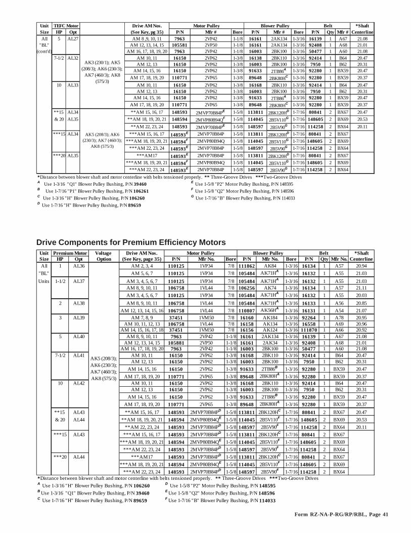
Form RZ-NA-P-RG/RP/RBL, Page 41
Unit Drive AM Nos. Motor Pulley Blower Pulley *ShaftSize HP Opt (See Key, pg 35) P/N Mfr # Bore P/N Mfr # Bore P/N Qty Mfr # CenterlineAll 5 AL27 AM 8 ,9, 10, 11 7963 2VP42 1-1/8 16161 2AK134 1-3/16 16139 1 A67 21.08
"BL" AM 12, 13, 14, 15 105581 2VP50 1-1/8 16161 2AK134 1-3/16 92408 1 A68 21.01(cont'd) AM 16, 17, 18, 19, 20 7963 2VP42 1-1/8 16003 2BK100 1-3/16 50477 1 A60 21.08
7-1/2 AL32 AM 10, 11 16150 2VP62 1-3/8 16138 2BK110 1-3/16 92414 1 B64 20.47AM 12, 13 16150 2VP62 1-3/8 16003 2BK100 1-3/16 7950 1 B62 20.31
AM 14, 15, 16 16150 2VP62 1-3/8 91633 2TB86A 1-3/16 92280 1 BX59 20.47AM 17, 18, 19, 20 110771 2VP65 1-3/8 89648 2BK80HC 1-3-16 92280 1 BX59 20.37
10 AL33 AM 10, 11 16150 2VP62 1-3/8 16168 2BK110 1-3/16 92414 1 B64 20.47AM 12, 13 16150 2VP62 1-3/8 16003 2BK100 1-3/16 7950 1 B62 20.31
AM 14, 15, 16 16150 2VP62 1-3/8 91633 2TB86A 1-3/16 92280 1 BX59 20.47 AM 17, 18, 19, 20 110771 2VP65 1-3/8 89648 2BK80HC 1-3/16 92280 1 BX59 20.37**15 AL34 **AM 15, 16, 17 148593 2MVP70B84PE 1-5/8 113811 2BK120HD 1-7/16 80841 2 BX67 20.47& 20 AL35 **AM 18, 19, 20, 21 148594 2MVP80B94QF 1-5/8 114045 2B5V110G 1-7/16 148605 2 BX69 20.53
**AM 22, 23, 24 148593 2MVP70B84PE 1-5/8 148597 2B5V90G 1-7/16 114258 2 BX64 20.11***15 AL34 ***AM 15, 16, 17 148593E 2MVP70B84P 1-5/8 113811 2BK120HD 1-7/16 80841 2 BX67
***AM 18, 19, 20, 21 148594F 2MVP80B94Q 1-5/8 114045 2B5V110G 1-7/16 148605 2 BX69***AM 22, 23, 24 148593E 2MVP70B84P 1-5/8 148597 2B5V90G 1-7/16 114258 2 BX64
***20 AL35 ***AM17 148593E 2MVP70B84P 1-5/8 113811 2BK120HD 1-7/16 80841 2 BX67***AM 18, 19, 20, 21 148594F 2MVP80B94Q 1-5/8 114045 2B5V110G 1-7/16 148605 2 BX69
***AM 22, 23, 24 148593E 2MVP70B84P 1-5/8 148597 2B5V90G 1-7/16 114258 2 BX64*Distance between blower shaft and motor centerline with belts tensioned properly. ** Three-Groove Drives ***Two-Groove DrivesA Use 1-3/16 "Q1" Blower Pulley Bushing, P/N 39460 E Use 1-5/8 "P2" Motor Pulley Bushing, P/N 148595B Use 1-7/16 "P1" Blower Pulley Bushing, P/N 106261 F Use 1-5/8 "Q2" Motor Pulley Bushing, P/N 148596C Use 1-3/16 "H" Blower Pulley Bushing, P/N 106260 G Use 1-7/16 "B" Blower Pulley Bushing, P/N 114033D Use 1-7/16 "H" Blower Pulley Bushing, P/N 89659
Belt
AK3 (230/1); AK5 (208/3); AK6 (230/3);
AK7 (460/3); AK8 (575/3)
AK5 (208/3); AK6 (230/3); AK7 (460/3);
AK8 (575/3)
TEFC Motor
Drive Components for Premium Efficiency MotorsUnit Voltage Drive AM Nos. Motor Pulley Blower Pulley *ShaftSize HP Opt Option (See Key, page 35) P/N Mfr No. Bore P/N Mfr No. Bore P/N Qty Mfr No. CenterlineAll 1 AL36 AM 2, 3, 4 110125 1VP34 7/8 111862 AK84 1-3/16 16134 1 A57 20.94
"BL" AM 5, 6, 7 110125 1VP34 7/8 105484 AK71HA 1-3/16 16132 1 A55 21.03Units 1-1/2 AL37 AM 3, 4, 5, 6, 7 110125 1VP34 7/8 105484 AK71HA 1-3/16 16132 1 A55 21.03
AM 8, 9, 10, 11 106758 1VL44 7/8 106256 AK74 1-3/16 16134 1 A57 21.11AM 3, 4, 5, 6, 7 110125 1VP34 7/8 105484 AK71HA 1-3/16 16132 1 A55 20.03
2 AL38 AM 8, 9, 10, 11 106758 1VL44 7/8 105484 AK71HA 1-3/16 16133 1 A56 20.85AM 12, 13, 14, 15, 16 106758 1VL44 7/8 110807 AK56HA 1-3/16 16131 1 A54 21.07
3 AL39 AM 7, 8, 9 37451 1VM50 7/8 16160 AK184 1-3/16 92264 1 A78 20.95AM 10, 11, 12, 13 106758 1VL44 7/8 16158 AK134 1-3/16 16558 1 A69 20.96
AM 14, 15, 16, 17, 18 37451 1VM50 7/8 16156 AK124 1-3/16 111870 1 A66 20.925 AL40 AM 8, 9, 10, 11 7963 2VP42 1-1/8 16161 2AK134 1-3/16 16139 1 A67 21.08
AM 12, 13, 14, 15 105881 2VP50 1-1/8 16161 2AK34 1-3/16 92408 1 A68 21.01AM 16, 17, 18, 19, 20 7963 2VP42 1-1/8 16003 2BK100 1-3/16 50477 1 A60 21.08
7-1/2 AL41 AM 10, 11 16150 2VP62 1-3/8 16168 2BK110 1-3/16 92414 1 B64 20.47AM 12, 13 16150 2VP62 1-3/8 16003 2BK100 1-3/16 7950 1 B62 20.31
AM 14, 15, 16 16150 2VP62 1-3/8 91633 2TB86B 1-3/16 92280 1 BX59 20.47AM 17, 18, 19, 20 110771 2VP65 1-3/8 89648 2BK80HA 1-3/16 92280 1 BX59 20.37
10 AL42 AM 10, 11 16150 2VP62 1-3/8 16168 2BK110 1-3/16 92414 1 B64 20.47AM 12, 13 16150 2VP62 1-3/8 16003 2BK100 1-3/16 7950 1 B62 20.31
AM 14, 15, 16 16150 2VP62 1-3/8 91633 2TB86B 1-3/16 92280 1 BX59 20.47 AM 17, 18, 19, 20 110771 2VP65 1-3/8 89648 2BK80HA 1-3/16 92280 1 BX59 20.37
**15 AL43 **AM 15, 16, 17 148593 2MVP70B84PD 1-5/8 113811 2BK120HC 1-7/16 80841 2 BX67 20.47& 20 AL44 **AM 18, 19, 20, 21 148594 2MVP80B94QE 1-5/8 114045 2B5V110F 1-7/16 148605 2 BX69 20.53
**AM 22, 23, 24 148593 2MVP70B84PD 1-5/8 148597 2B5V90F 1-7/16 114258 2 BX64 20.11***15 AL43 ***AM 15, 16, 17 148593 2MVP70B84PD 1-5/8 113811 2BK120HC 1-7/16 80841 2 BX67
***AM 18, 19, 20, 21 148594 2MVP80B94QE 1-5/8 114045 2B5V110F 1-7/16 148605 2 BX69***AM 22, 23, 24 148593 2MVP70B84PD 1-5/8 148597 2B5V90F 1-7/16 114258 2 BX64
***20 AL44 ***AM17 148593 2MVP70B84PD 1-5/8 113811 2BK120HC 1-7/16 80841 2 BX67***AM 18, 19, 20, 21 148594 2MVP80B94QE 1-5/8 114045 2B5V110F 1-7/16 148605 2 BX69
***AM 22, 23, 24 148593 2MVP70B84PD 1-5/8 148597 2B5V90F 1-7/16 114258 2 BX64*Distance between blower shaft and motor centerline with belts tensioned properly. ** Three-Groove Drives ***Two-Groove DrivesA Use 1-3/16 "H" Blower Pulley Bushing, P/N 106260 D Use 1-5/8 "P2" Motor Pulley Bushing, P/N 148595B Use 1-3/16 "Q1" Blower Pulley Bushing, P/N 39460 E Use 1-5/8 "Q2" Motor Pulley Bushing, P/N 148596C Use 1-7/16 "H" Blower Pulley Bushing, P/N 89659 F Use 1-7/16 "B" Blower Pulley Bushing, P/N 114033
AK5 (208/3); AK6 (230/3); AK7 (460/3); AK8 (575/3)
Premium Motor Belt

Form RZ-NA-P-RG/RP/RBL, Page 42
Drives - Model Series RGBL, RPBL, PGBL and Blower Cabinet RBL (cont'd)Drive Components for Two-Speed Motors
Unit Voltage Drive AM Nos. *ShaftSize HP Opt Option (See Key, page 35) P/N Mfr # Bore P/N Mfr # Bore P/N Qty Mfr # Centerline
1 AL45 AM 2, 3, 4 110125 1VP34 7/8 111862 AK84 1-3/16 16134 1 A57 20.94All AM 5, 6, 7 110125 1VP34 7/8 105484 AK71HA 1-3/16 16132 1 A55 21.03
"BL" 1-1/2 AL46 AM 3, 4, 5, 6, 7 110125 1VP34 7/8 105484 AK71HA 1-3/16 16132 1 A55 21.03Units AM 8, 9, 10, 11 106758 1VL44 7/8 106256 AK74 1-3/16 16134 1 A57 21.11
2 AL47 AM 4, 5 111681 1VP50 1-1/8 16156 AK124 1-3/16 111870 1 A66 20.92AM 6, 7, 8, 9 110151 1VP44 1-1/8 111862 AK84 1-3/16 92402 1 A59 21.28
AM 10, 11, 12, 13 110151 1VP44 1-1/8 112026 BK85HA 1-3/16 92225 1 B57 21.22AM 14, 15, 16, 17, 18, 19 110151 1VP44 1-1/8 112035 BK60 1-3/16 92239 1 BX54 20.93
3 AL48 AM 4, 5 111681 1VP50 1-1/8 16156 AK124 1-3/16 111870 1 A66 20.92AM 6, 7, 8, 9 110151 1VP44 1-1/8 111862 AK84 1-3/16 92402 1 A59 21.28
AM 10, 11, 12, 13 110151 1VP44 1-1/8 112026 BK75HA 1-3/16 92225 1 B57 21.22AM 14, 15, 16, 17, 18, 19 110151 1VP44 1-1/8 112035 BK60 1-3/16 92239 1 BX54 20.93
5 AL49 AM 8, 9, 10, 11 106257 2VP60 1-3/8 16168 2BK110 1-3/16 6010 1 B65 21.28AM 12, 13, 14, 15 106257 2VP60 1-3/8 16167 2BK90 1-3/16 92289 1 BX61 20.93
AM 16, 17, 18, 19, 20 106257 2VP60 1-3/8 92419 2TB70B 1-3/16 16143 1 B59 21.077-1/2 AL50 AM 10, 11 16150 2VP62 1-3/8 16168 2BK110 1-3/16 92414 1 B64 20.47
AM 12, 13 16150 2VP62 1-3/8 16003 2BK100 1-3/16 7950 1 B62 20.31AM 14, 15, 16 16150 2VP62 1-3/8 91633 2TB86 B 1-3/16 92280 1 BX59 20.47
AM 17, 18, 19, 20 110771 2VP65 1-3/8 89648 2BK80HA 1-3/16 92280 1 BX59 20.3710 AL51 AM 13, 14, 15, 16 91615 2MPV40-B54 1-5/8 89648 2BK80HA 1-3/16 92226 1 B58 20.47
AM 17, 18, 19, 20, 21, 22 91615 2MPV40-B54 1-5/8 110810 2BK70HA 1-3/16 92225 1 B57 20.37*Distance between blower shaft and motor centerline with belts tensioned properly.A Use 1-3/16 "H" Blower Pulley Bushing, P/N 106260. B Use 1-3/16 "Q1" Blower Pulley Bushing, P/N 39460.
AK5 (208/3); AK6 (230/3); AK7 (460/3)
2-Spd Motor BeltMotor Pulley Blower Pulley
Drive Table for Model RBHAVoltage Drive AM Nos. Motor Pulley Blower Pulley *Shaft
HP Opt Option (See Key, page 35) P/N Mfr # Bore P/N Mfr # Bore P/N Qty Mfr # Centerline1/4 AL2 AM 1, 2 4074 1VL34 1/2 111609 AK99 1 88560 1 A61 21.16
AM 3, 4 4074 1VL34 1/2 19111 AK84 1 50476 1 A58 20.941/3 AL3 AM 1, 2 4074 1VP34 1/2 111609 AK99 1 88560 1 A61 21.16
AM 3, 4 4074 1VP34 1/2 19111 AK84 1 50476 1 A58 20.94AM 5, 6, 7 4074 1VP34 1/2 18797 AK64 1 16132 1 A55 21.11
1/2 AL4 AM 1, 2 13580 1VL34 5/8 111609 AK99 1 16137 1 A62 21.66AM 3, 4, 5 105476 1VL44 5/8 16153 AK104 1 80836 1 A64 21.59AM 6, 7, 8 13580 1VL34 5/8 18797 AK64 1 16133 1 A56 21.61
AM 9, 10, 11 13013 1VM50 5/8 19111 AK84 1 88560 1 A61 21.343/4 AL5 AM 3, 4, 5 105476 1VL44 5/8 16153 AK104 1 80836 1 A64 21.59
AM 6, 7, 8 13580 1VL34 5/8 18797 AK64 1 16133 1 A56 21.61AM 9, 10, 11 13013 1VM50 5/8 19111 AK84 1 88560 1 A61 21.34
AM 12, 13, 14, 15, 16, 17, 18 7962 1VL40 5/8 111689 AK49 1 16131 1 A54 21.44AM 5, 6, 7 13013 1VM50 5/8 16153 AK104 1 111870 1 A66 22.16
AM 8, 9, 10, 11 13013 1VM50 5/8 19111 AK84 1 88560 1 A61 21.34AM 12, 13, 14, 15, 16, 17, 18 7962 1VL40 5/8 111689 AK49 1 16131 1 A54 21.44
AM 5, 6, 7 7/8 111870 1 A66 22.16AK8 (575/3) AM 8, 9, 10, 11 7/8 88560 1 A61 21.34
AM 12, 13, 14, 15, 16, 17, 18 7/8 16131 1 A54 21.44AM 5, 6, 7 13013 1VM50 5/8 16153 AK104 1 111870 1 A66 22.16
AM 8, 9, 10, 11 13013 1VM50 5/8 19111 AK84 1 88560 1 A61 21.34AM 12, 13, 14, 15, 16, 17, 18 7962 1VL40 5/8 111689 AK49 1 16131 1 A54 21.44
AM 19, 20, 21, 22, 23 105476 1VL44 5/8 105481 AK46 1 16131 1 A54 21.37AM 5, 6, 7 7/8 111870 1 A66 22.16
AM 8, 9, 10, 11 7/8 88560 1 A61 21.34AM 12, 13, 14, 15, 16, 17, 18 7/8 16131 1 A54 21.44
AM 19, 20, 21, 22, 23 7/8 16131 1 A54 21.37AM 8, 9, 10, 11 13013 1VM50 5/8 19111 AK84 1 88560 1 A61 21.34
AM 12, 13, 14, 15, 16, 17, 18 7962 1VL40 5/8 111689 AK49 1 16131 1 A54 21.44AM 19, 20, 21, 22, 23 105476 1VL44 5/8 105481 AK46 1 16131 1 A54 21.37
AM 8, 9, 10, 11 7/8 88560 1 A61 21.34AM 12, 13, 14, 15, 16, 17, 18 7/8 16131 1 A54 21.44
AM 19, 20, 21, 22, 23 7/8 16131 1 A54 21.37AM 11, 12, 13, 14, 15 5/8 16145 1 B58 21.54
AM 16, 17, 18, 19 5/8 50477 1 A60 21.57AM 20, 21, 22, 23 5/8 111870 1 A66 22.17
AM 11, 12, 13, 14, 15 106758 1VL44 7/8 101414 BK130 1 16145 1 B58 21.54AM 16, 17, 18, 19 106748 1VL40 7/8 19111 AK84 1 50477 1 A60 21.57AM 20, 21, 22, 23 37451 1VM50 7/8 16153 AK104 1 111870 1 A66 22.17
AM 13, 14, 15, 16, 17 87500 2VP36 7/8 89649 2BK100HA 1 92411 1 BX62 21.54AM 18, 19, 20, 21, 22, 23, 24 6599 2VP42 7/8 87504 2AK84 1 50477 1 A60 21.43
*Distance between blower shaft and motor centerline with belts tensioned properly. A Use 1" x H Blower Pulley Bushing, P/N 92203
AK5 (208/3); AK6 (230/3); AK7 (460/3);
AK8 (575/3)
Open Motor
AK1 (115/1); AK2 (208/1); AK3 (230/1)
AK5 (208/3); AK6 (230/3); AK7 (460/3);
AK8 (575/3)
2 AL8
AK1 (115/1); AK2 (208/1); AK3 (230/1); AK5 (208/3); AK6 (230/3); AK7 (460/3)
5 AL10
AK2 (208/1); AK3 (230/1) 3 AL9
Belt
AK1 (115/1); AK2 (208/1); AK3 (230/1); AK5 (208/3); AK6 (230/3); AK7 (460/3)
1 AL6
AL7
AK1 (115/1); AK2 (208/1); AK3 (230/1); AK5 (208/3); AK6 (230/3); AK7 (460/3)
AK8 (575/3)
1-1/2

Form RZ-NA-P-RG/RP/RBL, Page 43
Replacement Filters/Blockoff Plates - Model Series RGBL/RPBL/PGBL and Blower Cabinet ModelRBLThe filter information below and on the top of page 44 applies to Model Series RPBL, RGBL, PGBL and RBL manufactured beginning 9/91;filter information on the bottom of page 44 applies to units manufactured prior to 9/91.)
Replacement Filters - Model Series RGB and RPB and Blower Cabinet Model RBA
APPLICATION NOTES:Do not use 1" or 2" disposable filters on Models75-125 with over 2999 CFM; on Models 150-175 with over 4499 CFM, or Models 200-225with over 4999 CFM; on Models 250-300 withover 5499 CFM; on Model 350 with over 6499CFM; or on Model 400 with over 7399 CFM.Do not use 1" or 2" pleated filters on Models 75-125 with over 3999 CFM.
Filter Arrangements
Filter FilterCode Size 1" 2" 1" 2" 1" 2" 75/100/125 150/175/RBA 200/225 250/300 350 400
A 16 x 20 16445 104097 101607 101620 104105 104110 -- 2 1 -- -- 1B 20 x 20 16448 104098 101608 101621 104106 104111 -- -- 1 1 -- 2C 16 x 25 16447 104099 101609 101622 104107 104112 -- 2 1 -- 2 1D 20 x 25 16446 104100 101610 101623 104108 104113 1 -- 1 2 3 2E 25 x 25 119775 119776 119779 119780 119777 119778 1 -- -- 1 -- --
Blockoff Plates ("black" in the illustrations below)Horizontal 104086 104095 104086 104095 104086 104095 1 -- 1 4 -- 1Vertical 103807 104091 103807 104091 103807 104091 1 -- 1 1 1 1
Unit S ize and Quantity of Filters RequiredPermanent Pleated Disposable
Filter RGBL, RPBL & PGBL 400, 800, 1200 RGBL and RPBL 500, 600 RGBL and RPBL 700, 1050Type Qty Size 1" Filter 2" Filter Qty Size 1" Filter 2" Filter Qty Size 1" Filter 2" FilterDisposable 2 16 x 16 66596 104101 1 16 x 25 16447 104099 2 16 x 25 16447 1040991" or 2" 1 16 x 25 16447 104099 1 16 x 20 16445 104097 4 12 x 30 114328 114323
4 12 x 25 114327 114318 4 12 x 20 114326 114317 4 12 x 20 114326 1143174 12 x 30 114328 114323 4 12 x 25 114327 114318
Permanent 2 16 x 16 104102 104103 1 16 x 20 101607 101620 2 16 x 25 101609 1016221" or 2" 8 12 x 16 114334 114325 4 12 x 20 114332 114321 8 12 x 26 114333 114322
1 16 x 25 101609 101622 1 16 x 25 101609 1016224 12 x 26 114333 114322 4 12 x 26 114333 114322
Pleated 2 16 x 16 104104 104109 1 16 x 20 104105 104110 2 16 x 25 104107 1041121" or 2" 4 12 x 25 114330 114320 1 16 x 25 104107 104112 4 12 x 32 114331 104324
1 16 x 25 104107 104112 4 12 x 20 114329 114319 4 12 x 20 114329 114319 4 12 x 32 114331 114324 4 12 x 25 114330 114320
RPDBL 800, 1600 RPDBL 1000, 1200 RPDBL 1400Disposable 4 16 x 16 66596 104101 2 16 x 25 16447 104099 4 16 x 25 16447 1040991" or 2" 2 16 x 25 16447 104099 2 16 x 20 16445 104097 8 12 x 30 114328 114323
8 12 x 25 114327 114318 8 12 x 20 114326 114317 8 12 x 20 114326 1143178 12 x 30 114328 114323 8 12 x 25 114327 114318
Permanent 4 16 x 16 104102 104103 2 16 x 20 101607 101620 4 16 x 25 101609 1016221" or 2" 16 12 x 16 114334 114325 8 12 x 20 114332 114321 16 12 x 26 114333 114322
2 16 x 25 101609 101622 2 16 x 25 101609 1016228 12 x 26 114333 114322 8 12 x 26 114333 114322
Pleated 2 16 x 16 104104 104109 2 16 x 20 104105 104110 4 16 x 25 104107 1041121" or 2" 8 12 x 25 114330 114320 2 16 x 25 104107 104112 8 12 x 32 114331 104324
2 16 x 25 104107 104112 8 12 x 20 114329 114319 8 12 x 20 114329 1143198 12 x 32 114331 114324 8 12 x 25 114330 114320
5�!
5
55
555
5
�
�
� � �
� (
(
((
00 0
00 0
5
�! �!
�!�!�!
���� ��
������
��E�*�5�#�5��E�*#5$�#�5��0��0�� � ��E�*�$$���5
��E�.$$��E�=5$��E�*�5$�=$$Type of Filter
Average Efficiency
Average Arrestance
Disposable 1" Less than 20% 75%2" Less than 20% 80%
Permanent 1" Less than 20% 53% to 60%2" Less than 20% 64% to 67%
Pleated 1" 30% to 35% 90% to 93%Disposable 2" 30% to 35% 90% to 93%

Form RZ-NA-P-RG/RP/RBL, Page 44
�
(
0
5�
5
55
0
00
�!"�������*
00
00
�
(
55
55
�!"�������*
0000
�
�
(
(
(
(
�!"�������*
�
(
00
00
55
5
5
�!"�������
((
((
((
((
�
�
�!"�������
55
55
(�
�00
00
00
00
�!"�������
(
��
55
55
00
00
�!"�������* (
00
00
� 55
55
�!"�������*
�
�
((
((
00
00
�!"�������
PGBL, (C)RGBL, RPBL 400, 800, 1200;RPDBL 800, 1600 (2 sets)
PGBL, (C)RGBL, RPBL 400, 800, 1200;RPDBL 800, 1600 (2 sets)
PGBL, (C)RGBL, RPBL 400, 800, 1200;RPDBL 800, 1600 (2 sets)
A 16 x 16B 16 x 25C 12 x 25D 12 x 30
A 16 x 16B 16 x 25C 12 x 25D 12 x 32
A 16 x 16B 16 x 25C 12 x 16D 12 x 26
PGBL, (C)RGBL, RPBL 500, 600;RPDBL 1000, 1200 (2 sets)
PGBL, (C)RGBL, RPBL 500, 600;RPDBL 1000, 1200 (2 sets)
PGBL, (C)RGBL, RPBL 500, 600;RPDBL 1000, 1200 (2 sets)
A 16 x 20B 16 x 25C 12 x 20D 12 x 25
A 16 x 20B 16 x 25C 12 x 20D 12 x 25
A 16 x 20B 16 x 25C 12 x 20D 12 x 26
PGBL, (C)RGBL, RPBL 700, 1050;RPDBL 1400 (2 sets)
PGBL, (C)RGBL, RPBL 700, 1050;RPDBL 1400 (2 sets)
PGBL, (C)RGBL, RPBL 700, 1050;RPDBL 1400 (2 sets)
Filter Arrangements for 1" or 2" Disposable Filters (Options AW2 and AW7)
Filter Arrangements for 1" or 2" Disposable Pleated Filters (Options AW10 and AW11)
Filter Arrangements for 1" or 2" Permanent Filters (Options AW8 and AW9)
A 16 x 25B 12 x 20C 12 x 30
A 16 x 25B 12 x 20C 12 x 32
A 16 x 25B 12 x 26
Blockoff Plates:(1) P/N 106334;(4) P/N 114337
Blockoff Plates:(1) P/N 106332;(4) P/N 114336
Blockoff Plates:(1) P/N 106332;(4) P/N 114336
Blockoff Plates:(1) P/N 106334;(4) P/N 114335
Blockoff Plates:(1) P/N 106332;(4) P/N 114337
Blockoff Plate:(1) P/N 106333
Blockoff Plate:(1) P/N 106334
Blockoff Plate:(1) P/N 106334
Blockoff Plate:(1) P/N 106332
Replacement Filters/Blockoff Plates for Model Series RGBL/RPBL and Blower Cabinet Model RBLmanufactured prior to 9/91Filter Filter 1" 2" 1" 2" 1" 2" Unit Size and QuantityCode Size Disposable Disposable Permanent Permanent Pleasted Pleated of Filters Required
AW2 AW7 AW8 AW9 AW10 AW11 500 600 700/1050 400/800/1200A 16 x 16 66596 104101 104102 104103 104104 104109 -- -- -- 4B 16 x 20 16445 104097 101607 101620 104105 104110 4 4 -- 8C 16 x 25 16447 104099 101609 101622 104107 104112 4 4 8 --
�!"�������
�
�
�
�
(
(
(
(
(
(
(
(
��E�*.$$�;$$�#�$$
�
�
�
�
0
0
0
0
0
0
0
0
��E�*�$$�#$5$
�
�
�
�
0
0
0
0
(
(
(
(
��E�*5$$�%$$
�
�
�
�
����� �����
6
Blockoff PlatesCode P/N "X"
1 106332 1-1/2" (38mm)2 106333 2" (51mm)3 106334 5/8" (16mm)
���
�
��
��
���
�
��
��
Filter Removal and Installation Instructions - Applies only to RGBL and RPBL Series manufactured prior to 9/91Filter Removal1. Remove screw (1) from the filter rack and
remove the retaining angle.2. Rotate filter down and remove from unit. Slide
next filter over and rotate down and out. Repeatfor remaining filters in top row.
3. Remove screw (1) from filter rack and removeretaining angle.
4. Rotate filter up and out of rack. Slide the nextfilter over and rotate up and out. Repeat forremaining filters in the row.
5-8. Repeat Steps 3 and 4.9. See filter installation instruction label.
Filter Installation1. Insert filters in the bottom
row.2. Replace retaining angle and
insert screws (1).3. Insert filters in the next level.4. Replace retaining angle and
insert screw (1).5-7. Repeat Steps 3 and 4.8. Replace retaining angle and
insert screws (2).9. Replace filter cabinet door and
secure all latches and screws.
Replacement Filters/Blockoff Plates - currently manufactured "BL" Cabinets (cont'd)

Form RZ-NA-P-RG/RP/RBL, Page 45
Code 400
Optional Remote ConsoleOptional RC style remote console includes a mounting ring so that the console may be either recessed or wall mounted. The box is of 16 gauge steelwith knockout holes for field wiring. The cover is made of plastic with custom engraving. Order replacement parts for Option RC remote consoleby part number.
��#�;:65.��7
��#�;:65.��7��=�;:6%$��7
5�#5�=�:6#=<��7
%:6#5���7
��=�;:
6%$��7
#�5�#%:6==��7
401
402
403
Code Description P/N400 Remote Console Box - 10-1/16 x 6-5/8 x 2-5/8 107010
Remote Console Box - 15-1/16 x 6-5/8 x 2-5/8 107011401 Mounting Ring for 10-1/16" long box 107014
Mounting Ring for 15-1/16" long box 107015402 Light for Red Lens, Solico #5TD1L-R-B5 101889403 SPDT Switch, Cutler Hammer #7505K6 101901404 DPDT Switch, Cutler Hammer #7561K6 101900405 Single-Stage Heating Thermostat 91919406 Two-Stage Heating Thermostat 93435
Single-Stage Heating/Cooling Thermostat 73411Two-Stage Heating/Cooling Thermostat 93437
407 Potentiometer (See Code 387, page 29) 16110
400
Remote Console Components by Option - Options RC1-RC12Component Function In Options CodeBlower On Light Lights when blower is operating RC 1-12 402Burner On Light Lights when burners are lit RC 1-12 402Dirty Filter Light Lights when the pressure switch indicates that RC 2, 4, 6, 402
filters need to be cleaned or replaced 8, 12On/Off Control "On" position energizes the unit for thermostat RC3, 4, 7, 403Switch control. "Off" position de-energizes the unit and 8, 11, 12
closes optional automatically controlled outsideair dampers.
Summer/Winter/ "Summer" position energizes the blower only. RC 5, 6, 10 404Off Control "Winter" position energizes the unit for thermostatSwitch control. "Off" position de-energizes the unit and closes
optional automatically controlled outside air dampers.Heat/Vent/Cool "Heat" position energizes the unit for thermostat RC 7, 8, 404Control Switch control. "Vent" position energizes the blower and 11, 12
opens optional automatically controlled outside airdampers. "Cool" position energizes the blower, thedampers, and the cooling unit.
Cooling Light Lights when cooling system is operating RC 7, 9, 40211, 12
Knockout Hole Locations (measuredfrom centerlines)
Disconnect Switches
Disconnect SwitchesDescription Outdoor P/N Same as Opt Indoor P/N Same as Opt30 Amp 300V Non-Fusible 40269 CP5 40267 CP130 Amp 300V Fusible (less fuses) 87147 CP6 40268 CP230 Amp 600V Non-Fusible 50367 CP7 50365 CP330 Amp 600V Fusible (less fuses) 50368 CP8 50366 CP460 Amp 240V Fusible (less fuses) 161459 CP17 161467 CP2760 Amp 600V Fusible (less fuses) 161461 CP20 162835 CP33
Console Dimensions (wall mounted - not recessed) Console Options Optional Control Length* Height* DepthRC 1, 2, 3, 4, 5, 6, 7, 8, 9, 10, 12 without 10-3/4" 7-5/8" 2-5/8"RC 1, 2, 3, 4, 5, 6, 9 with 10-3/4" 7-5/8" 2-5/8"RC 7, 8, 10, 12 with 15-3/4" 7-5/8" 2-5/8"RC 11 with & without 15-3/4" 7-5/8" 2-5/8"* Subtract 5/8" when recessing console (not using wall-mounting ring)

Form RZ-NA-P-RG/RP/RBL, Page 46
Optional Outside Air Inlet Hood (Weatherhood)
Code 501 - 30% Outside Air Hood (Part ofOptions AR6 and AR7) -- apply to outdoor unitsonly
Weatherhoods and Components: 500/600 750/1050 400/800/1200/RBLCode Description 75/100/125 150/175/RBA 200/225 250/300 350 400
500 Complete 100% Outside Air Inlet Hood 106201 106202 106203 106204 106205 106206500A Weatherhood Left Side500B Weatherhood Right Side500C Weatherhood Top 100227 100228 100229 100230 100231 100232500D Weatherhood Bottom 100234 100235 100236 100237 100238 100239500E Louver Assembly 103773 103774 103775 103776 103777 103778501 30% Outside Air Inlet Hood Assy (part
of Options AR6 and AR7)105117 105118 105119 105120 105121 105122
501A 30% Air Inlet Hood Cover 103797 103798 103799 103800 103801 103802501B 30% Air Inlet Hood Right Side501C 30% Air Inlet Hood Left Side
100216100217
100264100265
5$$'A� ����6�0���/*�(�
/�0�������!�(������ 7
5$$ �������0�
����
5$$- ���������
5$$�������0�����5$$���/8��
�**��(+
Code 500 - ScreenedOutside Air Hood for100% Outside Air
5$#'�������0�
5$# ������0�
5$#�'�8��
��0��� �����/�0�������!�(������ 3
Roof Curbs
Curb Hardware and TapeP/N Description
16247 Hex Head Cap Screw 5/16" x 3/4" long1035 Hex Nut 5/16"-18
16243 Lag Screw 5/16" x 1" long1333 Lockwasher 5/16"
66302 50 ft, 1/4" x 1-1/4" Foam Sealant Tape 80013 50 ft, Curb Cap Tape, 1/4" x 4"
Roof Curb RBA/ RBLDescription 75/100/125 150/175 200/225 250/300 350 400 400 500/600 700 800 1050 1200 RBHA
105215 105216 105217 105218 105219 105220 107251 107252 107253 107254 107255 107256 112115 111944
Curb Side Assy (2) 105221 105221 105221 105221 105221 105221 107257 107258 107258 107258 107259 107259 112114 111940Curb Front & Back Assy (2) 104652 104653 104654 104655 104656 104657 104657 104655 104656 104657 104656 104657 104653 104657
104673 104674 104675 104676 104677 104678 107270 107271 107272 107273 107274 107275 -- 111381
Curb Side Assy (2) 104649 104649 104649 104649 104649 104649 107276 107277 107277 107277 107278 107278 -- 111385Curb Front & Back Assy (2) 104652 104653 104654 104655 104656 104657 104657 104655 104656 104657 104656 104657 -- 104657
174067 174068 174069 174070 174071 174072 174102 174103 174104 174105 174106 174107
Curb Side Assy (2) 104649 104649 104649 104649 104649 104649 104649 104649 104649 104649 104649 104649Curb Side Assy (2) 173607 173608 173609 173610 173611 172866 172867 172868 172869 172870 172871 172872Curb Front & Back Assy (2) 104652 104653 104654 104655 104656 104657 104657 104655 104656 104657 104656 104657
174073 174074 174075 174076 174077 174078 174108 174109 174110 174111 174112 174113
Curb Side Assy (2) 104649 104649 104649 104649 104649 104649 104649 104649 104649 104649 173606 173606Curb Side Assy (2) 173873 173874 173875 173876 173877 173878 172879 172880 172881 172882 172883 172884Curb Front & Back Assy (2) 104652 104653 104654 104655 104656 104657 104657 104655 104656 104657 104656 104657
Model Series RGBL and RPBLModel Series RGB and RPB
Complete Curb Pkg with Cooling Coil Cabinet & Downturn Plenum, AU11, AU12, AU13, or AU14
Complete Curb Pkg with Cooling Coil Cabinet, AU2 or AU3
Complete Curb Pkg with a Downturn Plenum
Complete Curb Package - Std System
NOTE: For a roof curb for a Model RPDBL, contact yourdistributor.

Form RZ-NA-P-RG/RP/RBL, Page 47
Assembled Replacement Downturn Plenum CabinetIf due to freight damage, incorrect ordering, or some other unforeseen reason, a downturn plenum cabi-net needs to be added to the system, order the appropriate part number for a factory-assembled cabinetfrom the table on the left. Since this cabinet is not factory-built on the system curb cap, a platform or legsmust be field fabricated to support the downturn plenum cabinet. Do not support the downturn plenumcabinet with the ductwork. The ductwork connection and roof opening must be flashed and/or sealed toprevent water from entering the ductwork or the building.Instructions for Attaching Replacement Cabinet1) If the heater is operating, turn off the gas and the electric.2) Position the "open" side of the cabinet against the heater discharge. The top and side posts of the
cabinet will "overlap" the heater. Fasten on both sides and across the top with field-supplied, weather-resistant sheet metal screws.
3) Provide field-fabricated, weather-resistant support for the cabinet.4) Attach ductwork to the flange on the cabinet. Flash and/or seal the ductwork and the roof opening to
prevent water from entering the building or the ductwork.5) Turn on the electric and the gas. Follow the instructions on the lighting instruction plate. Check the
heater for proper operation.
Optional Downturn Plenum and Discharge Damper - Applies to Model Series RGB/RPB,Model Series RGBL/RPBL, and Blower Cabinet Model RBL
"Attached"Downturn
Plenum withDoor Panel
Removed
"Unattached"Downturn
Plenum
510
511
513 514
515
517
75-125 147140150-175 147141200-225 147142250-300 147143
350 147144400 147145
500, 600 147147750, 1050 147148
400, 800, 1200 147146Model RBL 147146
Assembled Replacement Downturn Plenum Cabinet less Curb Cap (no dampers)RGB/RPB Series
RGBL/ RPBL Series
Downturn Plenum Components: 500/600 750/1050 400/800/1200Code Description 75/100/125 150/175 200/225 250/300 350 400510 Downturn Plenum Bottom Assy 103586 103587 103588 103589 103590 103591511 Downturn Plenum Top Assy 103611 103612 103613 103614 103615 103616512 Downturn Plenum Top Assy Insulation Retainer 100253 100254 100255 100256 100257 100258513 Downturn Plenum Front Panel Assy 103617 103618 103619 103620 103621 103622
Downturn Plenum Front Panel Assy (w/double wall, Opt AY3) 105547 105548 105549 105550 105551 105552514 Downturn Plenum Door Assy
Downturn Plenum Door Assy (w/double wall, Option AY3)515 Downturn Plenum Corner Post516 Downturn Plenum Corner Post Cap517 Downturn Plenum Cabinet Leg518 Downturn Plenum Cabinet Leg Cap
Downturn Plenum Cabinet Leg Cap519 Downtrun Plenum Top Insulation Clamp520 Door Latch Assy - All cabinet Doors521 Discharge Damper (not illustrated) 15868 15869522 Discharge Damper and Frame Assy 105421 105422523 Discharge Damper Motor Base524 Discharge Damper Motor Cover525 Damper Motor, Honeywell M6161A1001526 Auxiliary End Switch, Honeywell 201052A527 Shaft528 Damper Arm, Honeywell 26026K529 Ball Joint, Honeywell 27518530 Damper Rod, 9-1/2" long
112974
113873113874
(2)100027100069100070
(4)110537
12634105423
(2)100349(2)104114(2)114761(2)100072
(2)12636114467
114429114430113775
(2)12635

Form RZ-NA-P-RG/RP/RBL, Page 48
��!���!( ���
���
�!�
�!��
�!�
�!�
���
�!�(
������
�!�
���
���
�!��
�4�
�4�
�!!
�!�(
�����!�
�!�
�!�
�!�
�4�
�4�
�4�
�4�
���
����!��
�4�
�4��!�(
�!!
�!���!�(
�4!
�4�
Optional Cooling Coil Cabinet - Applies to Model Series RGB/RPB manufactured prior to5/99 (identified as Option AU1) - See below for units manufactured beginning 5/99.
549544
559
547
557
Cooling Coil Cabinet OptionAU1 (cooling coil cabinet
manufactured prior to 5/99)(side attached to ductwork or
downturn plenum is illustrated)
Optional Cooling Coil Cabinet - Applies to Model Series RGB/RPB and Model Series RGBL/RPBL manufactured beginning 5/99 (Options AU 2, 3, 11, 12, 13, 14)NOTES: A system with a cooling coil cabinet (Option AU2, AU3, AU11, AU12, AU13, or AU14) requires a special curb cap. Thiscooling coil cabinet is designed to be factory ordered with the system. Although it is shipped separately for field installation, thiscooling coil cabinet is not designed to be added to an already installed system.For a replacement cooling coil, contact your distributor; supply all model and rating plate information.
543556
541
558
Code Description 75, 100 125 150, 175 200, 225 250, 300 350 400541 Duct Flange Assembly 107394 107395 107396 107397 107398 107399 107400542 Cabinet Bottom Pan 100000 100000 100001 100002 100003 100004 100005543 Top Rear Panel 100029 100030 100031 100032 100033 100034 100035544 Coil Cabinet Btm Front
& Rear Panel (2)100036 100037 100038 100039 100040 100041 100042
545 Cabinet Bottom Front 107366 107077 107078 107079 107080 107081 107082546 Left Rear Cabinet Leg 100009547 Left Front Cabinet Leg 100007548 Right Rear Cabinet Leg 100008549 Right Frnt Cabinet Leg 100006550 Duct Side Left 107105551 Duct Side Right 107106552 Duct Side Top 107098 107099 107100 107101 107102 107103 107104553 Hanger Angle554 Top Coil Support 107379 107091 107092 107093 107094 107095 107096555 Drip Pan Assy 107402 107403 107404 107405 107406556 Right Side Panel Assy557 Left Side Panel Assy558 Btm Left Side Assy559 Casing Top 100052 100053 100054 100055 100056560 Rubber Grommet
561 Bottom Coil Deflector 107381 107084 107085 107086 107087 107088 107089562 Top & Btm Duct
Connector (2)107426 107427 107428 107429 106338 106339 106340
563 Side Duct Connector
100013100011100012100010107105107106
(2) 11012
107401107421107422107423
111067, Kennard #500-1/4"100051
15021, Kennard #1020T-3/4"102607, Kennard #1020T-1/2"39852, Kennard #1625 1-1/4"
(2) 106395
Illustration is a CoilCabinet for a Chilled
Water Coil with aDownturn Plenum
(Vertical Discharge)for Sizes 250 - 1200
Illustration is a Coil Cabinetfor a DX Coil with aDownturn Plenum (VerticalDischarge) for Sizes 75 - 225
* Refer to Option AUcolumn in replacementparts table on page 51.**Replacementinformation for dischargedampers is the same as onpage 49.
Coil Cabinet Option DescriptionOpt* Type of Coil DischargeAU2 Chilled Water HorizontalAU3 DX HorizontalAU11 Chilled Water VerticalAU12 Chilled Water Vertical with
Dampers**AU13 DX VerticalAU14 DX Vertical with
Dampers**AY3 Double Wall Cabinet
Construction
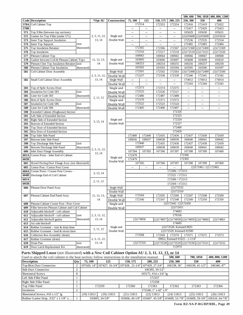
Form RZ-NA-P-RG/RP/RBL, Page 49
Parts Shipped Loose (not illustrated) with a New Coil Cabinet Option AU 2, 3, 11, 12, 13, or 14Used to attach the coil cabinet to the heat section; follow instructions in the installation manual. 500, 600 700, 1050 400, 800, 1200Description Qty 75, 100 125 150, 175 200, 225 250, 300 350 400Top/Btm Duct Connectors 2 107426, 14" 107427, 16-3/4" 107428, 21-1/4" 107429, 27-3/4" 106338, 36" 106339, 41-1/2" 106340, 47"Side Duct Connectors 2Sheetmetal Screws 8Left Side Filler Panel 1Right Side Filler Panel 1Top Filler Panel 1 172360 172361 172362 172363 172364Insulation 2Sheetmetal Screws, #10 x 1/2" lg › (19) 11813 (19) 11813 (21) 11813 (22) 11813 (24) 11813 (25) 11813 (26) 11813Rubber Gasket Strip, 3/32" x 1-1/8" x … 1 103606, 40-1/8" 103607. 45-5/8" 103608, 53-7/8" 103609, 59-3/8" 106310, 64-7/8"
172358
103605, 34-5/8"
106395, 19-1/2"105171, #14 x 3/4" lg
172357
172359172546, 1" x 42" x 9"
500, 600 700, 1050 400, 800, 1200Code Description *Opt AU Construction 75, 100 125 150, 175 200, 225 250, 300 350 400570A Coil Cabinet Top 172353 172354 172416 172419 172422570B -- -- -- -- 172417 172420 172423571 Top Filler (between top sections) -- -- -- -- 105629 105630 105631572 Gasket for Top Filler (under 571) -- -- -- -- (2)103608 (2)103609 (2)103610573 Inner Top Support Insulation -- -- -- -- 172536 172535 172534574 Inner Top Support -- -- -- -- 172482 172483 172484575 Top Insulation Retainer 172366 172367 (2)172368 (2)172400 (2)172369576 Top Insulation 172517 172518 (2)172519 (2)172521 (2)172520577 Plenum Cabinet Top 100064 100065 100066 100067 100068578 Gasket between Coil & Plenum Cabinet Tops 103606 103607 103608 103609 103610579 Plenum Cbnt Top Insulation Retainer 100254 100255 100256 100257 100258580 Plenum Cabinet Top Insulation 103593 103594 103595 103596 103597581 Coil Cabinet Door Assembly Single Wall 172502 172503 (3)172498 (3)172499 (3)172500
Double Wall 172338 172339 172340 172341 172342582 Small Coil Cabinet Door Assembly Single Wall -- -- -- -- 174012 174013 174014
Double Wall -- -- -- -- 172343 172344 172345583 Top of Split Access Door 172374 172375 -- -- --584 Insulation for Code 583 172526 172527 -- -- --585 Liner for Code 583 Double Wall 172487 172488 -- -- --586 Btm of Split Access Door 172371 172372 -- -- --587 Insulation for Code 586 172523 172524 -- -- --588 Liner for Code 586 Double Wall 172496 172497 -- -- --590 Extended Cabinet (Doghouse) Section 591 Left Side of Extended Section592 Right Side of Extended Section593 Bottom of Extended Section594 Top Door of Extended Section595 Btm Door of Extended Section596 Top Inlet Side Panel 172480 172440 172435 172436 172437 172438 172439597 Bottom Inlet Side Panel 100036 100037 100038 100039 100040 100041 100042598 Top Discharge Side Panel 172435 172436 172437 172438 172439599 Bottom Discharge Side Panel 100038 100039 100040 100041 100042600 Inlet Duct Flange Assembly 107394 107395 107396 107397 107398 107399 107400
601A 172478601B 172479602 107396 107397 107398 107399 107400603 Center Post / Center Post Cover -- -- -- --
604A604B605A605B606 Plenum Door Panel Assy Single Wall
Double Wall607 Plenum Cabinet End Panel Assy Single Wall 172505 172506 172507 172508 172509
Double Wall 172347 172348 172349 172350 172350608 Plenum Cabinet Corner Post / Post Cover609 Filler between Plenum Cabinet and Coil Cabinet610 Adjustable blockoff - coil cabinet611 Adjustable blockoff - coil cabinet612 Adjustable blockoff gasket (2)174857 (2)174858 (2)174859 (2)174860 (2)174861613 Air side blockoff614 Rubber Grommet - vent & drain lines615 Rubber Grommet - feed & return lines616 Collection Box Assembly (drain) 173569 173570 173571 173572 173573617 Rubber Grommet (drain)618 Drain Pan (2)173528 (2)173529 (2)173530 (2)173531 (2)173532619 Door Latch Replacement Kit
(not illustrated)
Hrzntl Dschrg Duct Flange Assy (not illustrated)
(not illustrated)
(not illustrated)
Corner Posts - Inlet End of Cabinet
(not illustrated)
(not illustrated)
(not illustrated)
(not illustrated)
3, 13, 14
2, 11, 12
11, 12, 13, 14
Corner Posts / Corner Post Covers - Discharge End of Coil Cabinet
2, 3, 11, 12, 13, 14
11, 12, 13, 14
(2)172442 / (2)172450
172304 / 172311172306 / 172313
(2)172532(2)172310
2, 3, 11, 12, 13, 14
2, 11, 12
172327
2, 3, 11, 12, 13, 14 (2)172316
Single and Double Wall
172326
3, 13, 14
172325172324
172460172459
100037
2, 3, 11, 12, 13, 14
174685
2, 3, 11, 12, 13, 14
(2)172451174683
172306 / 172313172321 / 172311
Single and Double Wall
Single and Double Wall
172306
2, 11, 12(2)172528, Kennard #825
(2)172529, Kennard #2500
Single and Double Wall
179336
(2)172461 / (2) 172462
Single and Double Wall
Single and Double Wall
Single and Double Wall
Single and Double Wall
172504172346
39852, Kennard #1625 - 1-1/14"
107395
(2)174856
173568
112974
172305
172314
172365172516100063103605100253103592172501172337
172373172525172486172370172522172495
172440

Form RZ-NA-P-RG/RP/RBL, Page 50
761
765
767
766
768
755
770
759 793
767
769
792765
781 772 755 750
709
764
788791 790
Model RBL/RBA/RBHA Blower Cabinets - Cabinet Parts and BlowersModel RBA is a stand-alone blower cabinet comparable in size and capacity to the cabinet that is a factory-assembled portion of packaged ModelsRGB/RPB 150.Model RBHA is a Model RBA blower cabinet designed for special applications requiring inlet air temperatures above that recommended by themotor manufacturer. The blower motor, bearings, and adjustable drive are mounted in a weatherized housing external to the airstream.Model RBL is the "stand-alone" blower cabinet comparable in size and capacity to the cabinet that is a factory-assembled portion of all RGBL andRPBL ModelsNOTE: Model RBL and RBA cabinet parts may be of either uninsulated single-wall construction, insulated single-wall construction, or double-wallconstruction which consists of two metal panels with insulation between. Select the replacement part that matches the original construction. ModelRBHA is only available in insulated single-wall construction.
Model RBA
Code Description RBA RBHA RBL Code Description RBA RBHA RBL750 Bottom Assy solid 103753 112614 -- 766 Duct Flange Side (2) 110093
duct opening -- 767 Duct Flange Top 110092751 Btm Right solid -- -- 106244 768 Duct Flange Bottom 110092
Half duct opening -- -- 105608 769 Corner Post (internal)(2)752 Bottom Left solid -- -- 106240 770 Corner Post Cap (2)
Half duct opening -- -- 104367 771 Intermediate Post (internal) -- 104373 114762753 Bottom Support (2) -- -- 105637 772 Intermediate Post Cap (2) --754 Bottom Insulation Retainers 111013 773 Top Front Panel (internal) -- 112376 105612
111017 774 Bottom Front Panel (internal) -- -- 105616755 Door Assy without insulation 111281 -- 111281 775 Vertical Blower Support - Left -- -- 106299
(2) with insulation 100347 112600 100347 776 Vertical Blower Support - Right -- -- 106943double wall 104115 -- 104118 777 Horizontal Blower Support (2) 31576
756 Door support (2) 100073 112607 -- 778 Cabinet Leg - Left (internal) -- -- 105603757 Filter Section without insulation -- -- 111282 779 Cabinet Leg - Right (internal) -- -- 105604
Door Assy (2) with insulation -- -- 106276 780 Inner Front Wrapper --758 Door Latch Assy 781 Left Inner Side Panel Assy -- 112602 --759 End 100% opening, uninsulated 111990 -- 111286 782 Right Inner Side Panel Assy -- 112603 --
Panel 100% opening, with insulation 103643 783 Mtr Base Support Rail (internal) -- 112704 --Assy 100% opening, double wall 105542 -- 105546 784 Bearing Block Spprt (internal) (2) -- 112371 --
solid, uninsulated 112109 103618 111290 785 Right Side Mtr support (internal) -- 112383 --solid, with insulation 103618 -- 103622 786 Left Side Mtr Support (internal) -- 112382 --
solid, double wall 105548 -- 105552 787 Mtr Compartment Frnt Legs (2) -- 112381 --30% opening, uninsulated 112108 -- 111292 788 Mtr Compartment Rear Legs (2) -- 112380 --
30% opening, with insulation 105112 -- 105116 789 Mtr Cmprtmnt Side door Assy -- 112604 --30% opening, double wall 105554 -- 105558 790 Motor Cmprtmnt Rear Legs (2) -- 112384 --
760 End Panel without filters 100080 791 Motor Compartment Top -- 112388 --Support with filters 104080 -- 100080 792 Motor Compartment Bottom (2) -- 112385 --
761 Cabinet Top without insulation 110419 -- -- 793 Motor Compartment Door -- 112386 --762 Top Support 105602 794 Electrical Panel -- 112375 --763 Cbnt Top (Front) without insulation -- 112376 111284 795 Electrical Box 100092 -- 100092764 Cabinet without insulation -- 112377 105598 796 Electrical Box Cover 100095 -- 100095
Top (Rear) with insulation -- -- 106288 797 Blower Adapter Back Assy -- -- 106294765 End Wrapper 110095
110387
112974
103639
112882110421110423
100076
110420
110422114761100072
104372
110388
111985
114224114222
ModelRBHA

Form RZ-NA-P-RG/RP/RBL, Page 51
6�79������*�*������� ����9�*���*
��2
����!��2
#�.:1����-�������
����9�*���
�����2��������01��02���-���!���������2
��������
763767
797766
765
768
755
772
757
770
759
764 Code 758 -ReplacementDoor LatchKit, P/N112974
Assembly sequence for installingreplacement door latch.
Model RBL
�#���$����%��&���'�%�'���( "�
�#���$���'�%�)*�
�#���$���� �+�)*�
�*,,�- ..��
�#���$����%��#��&��� /*��'���( "�
Code 799 forRBA -MotorAdjustmentBracketused on RBAwith lessthan 1HPMotor
Code 800 for RBA - ReplacementHardware Bag for Code 799
(6) BoltsP/N 16247
(2) Bolts, P/N 16248; Nuts, P/N6445; Washer, P/N 1087
802
804
(2) Rod Bolts,P/N 12489 803
Code 801 for RBA with motorsless than 1HP
Codes 802-804 for RBA and RBHA with1-5HP Motor
Code Description Qty RBA RBHA RBL798 2 -- -- 106698 (< 15HP mtr)
1 -- -- 149008 (15 & 20 HP)799 1 44411 -- 106274 (< 15HP mtr)
1 (Less than 1HP) -- 149009 (15 & 20 HP)799A Motor Adjustment 1 -- -- 105633 (< 15HP mtr)
Angle 1 -- -- 149010 (15 & 20 HP)800 Hardware Bag (for motors less than 1 HP) 1 --801 1 44410 -- --802 1 12579, 1-3 HP mtr 12578 106295
12578, 5HP motor (Assembly)803 Motor Mounting Plate Left Support 1 --804 Motor Mounting Plate Right Support 1 --805 Blower Housing and Wheel 1360, A12-12AC 112606, A12-12AC unpainted (2) 14469, Lau 15 x 11806 Blower Shaft 1 11303, 1" x 22" lg 112608, 1" x 45" lg 13589, 1-3/16 x 48" lg807 Bearings 2 10437 15298 14474 (< 10 HP)808 Bearing Bracket 2 -- -- 24233 (< 10 HP)809 Heavy Duty Blower (15-20HP Mtrs) Rt 1 -- -- 106937, 15 x 11810 Heavy Duty Blower (15-20HP Mtrs) Lft 1 -- -- 106938, 15 x 11811 1 -- -- 106941, 1-7/16" x 53" lg812 Blower Shaft Key for Heavy Duty Blwr 4 -- -- 134638813 2 -- -- 170108 (replaces 106942)814 Class II Blower Support - Right Side 1 -- -- 149520815 Class II Blower Support - Left Side 1 -- -- 149521816 Filter Rack Middle 1" & 2" Filters 1 104059 -- --817 Filter Rack Btm 1" & 2" Filters 1 104073 -- --818 Filter Rack Top 1" Filters 1 -- -- 114721819 Filter Rack Btm 1" Filters 1 -- -- 114713820 Filter Rack Rear 1" Filters 2 -- -- 114709821 Filter Rack Front 1" Filters 2 -- -- 114697822 Filter Rack Rear 2" Filters 1 -- -- 114725823 Filter Rack Btm 2" Filters 1 -- -- 114717824 Filter Rack Rear 2" Filters 2 -- -- 114705825 Filter Rack Front 2" Filters 2 -- -- 114693
Motor Adjustment Bracket Assembly
Motor Mount Support Assembly
64940
1257712576
RBL - see illustrations on pg 52
RBA - see btm of page; RBL-see pg 52
RBL - see illustrations on pg 55
RB(H)A-see below; RBL - see pg 52
Pillowblock Bearings, Dodge #P2BS2107R, 1-7/16"
Heavy Duty Blower Shaft 15-20HP Mtr
Motor Mounting Plate
Motor Mounting Strap 12" (for < 1 HP)

Form RZ-NA-P-RG/RP/RBL, Page 52
800-695-1901 www.RezSpec.com©2006 Thomas & Betts Corporation, All rights reserved.MANUFACTURER OF HEATING, COOLING, AND VENTILATING SYSTEMS5/06 OG POD Form RZ-NA-P-RG/RP/RBL (Version A)
Blower,bearing
support andmotor on aModel RBL
with up to 5HPMotor
Model RBL with 15 - 20 HP Motor
Model RBL(cont'd)
�������/����� �*�
�������/����� �*�
���������'� ����##�5�$
���������'� ����##�5��
����9�*������##�5�#
����9�*������##�5�=
=�; ������=��5=
5�#% ������#%�.�
Motor Mounting Bolts
3/8" Bolt
5/16" Bolt
RBA/RBHA/RBL Blower Cabinets (cont'd) - Blowers and Components
Blower Triangular Bearing Mountingfor RBL with a 7-1/2 or 10 HP MotorDescription P/NLeft Bearing Support Assy 112971Right Bearing Support Assy 112972Pillowblock Bearing, Sealmaster 1/16" (2)1129731/2-13 x 2" Cap Screw GR-8 (4)1113041/2-13 Nut GR-8 (4)1113051/2 Lockwasher (4)1113061/4-20 Cap Screws (6)162461/4-20 Lock Nut (6)10650