improvement in capacitive performances of efficient … inverters once it is implemented with...
TRANSCRIPT

Sangno et al., Cogent Engineering (2018), 5: 1455407https://doi.org/10.1080/23311916.2018.1455407
ELECTRICAL & ELECTRONIC ENGINEERING | RESEARCH ARTICLE
Improvement in capacitive performances of efficient micro electro mechanical system (MEMS) based power inverterRalli Sangno1,2, R.K. Mehta2 and Santanu Maity3*
Abstract: In this paper different electrostatic interdigitated comb designs for the new concept of MEMS based DC–AC capacitive power inverter for the solar photovoltaic ap-plications has been compared and tested on the basis of different structures and ma-terials used as a frame for the proposed model. To obtain better the performance and power conversion efficiency of the interdigitated comb drive capacitive DC/AC inverter at very low input voltage some structural parameters of the proposed model has been varied such as increase the number of comb fingers; reduced the gap between the fingers of the interdigitated comb with increase in thickness of the fingers and made uniformly tapered at its edges. As a structural material for the proposed model the polysilicon and indium antimonite has been employed, simulated, compared and tested and in COMSOL Metaphysics 5.0 environment with different comb structure to get better performances for solar photo voltaic application. The proposed MEMS DC/AC power inverter model can easily compete with the commercially available semicon-ductor inverters once it is implemented with efficient fabrication technology due to its certain merits over semiconductor power inverter in terms of miniaturized size, pure sinusoidal output voltage and current, regulated output frequency, ultra low power consumption, very low cost and off course very small or minimal power loss.
Subjects: MEMS; Industrial Electronics; Microelectronics; Power Electronics
Keywords: MEMS; actuator; inverter; miniaturization; solar cell
*Corresponding author: Santanu Maity, Electronics and Communication Engineering, Tezpur University, Napaam, Tezpur, Sonitpur, Assam 784 028, India E-mail: [email protected]
Reviewing editor:Wei Meng, Wuhan University of Technology, china
Additional information is available at the end of the article
ABOUT THE AUTHORSSantanu Maity is working as Assistant Professor in Electronics and Communication Engineering Department, Tezpur University. His research interests include solar cell, RF-MEMS, Antenna, High speed semiconductor devices, Semiconductor gas sensor.
Mr Ralli Sangno completed BE in Electrical Engineering in 2006 from Government Engineering College, Shamlaji Road, Modasa, Gujarat and MTech in Power System Engineering in 2009 from North Eastern Regional Institute of Science and Technology, Nirjuli, Arunachal Pradesh, India. Currently he is working as Assistant Professor, Electrical Engineering Department at NIT, Arunachal Pradesh and persuing his PhD in NERIST, Nirjuli. His area of interest includes Power Quality, Renewable Sources of Energy, MEMS, Distributed Generation and Power System Control.
PUBLIC INTEREST STATEMENTIn this work the simulation of MEMS based DC-AC capacitive power inverter for the solar photovoltaic applications has been proposed. To obtain better the performance and power conversion efficiency of the interdigitated comb drive capacitive DC/AC inverter at very low input voltage some structural parameters of the proposed model has been varied. The proposed will be an appropriate alternate of semiconductor switch based PV inverter technology.
Received: 01 January 2018Accepted: 17 March 2018First Published: 22 March 2018
© 2018 The Author(s). This open access article is distributed under a Creative Commons Attribution (CC-BY) 4.0 license.
Page 1 of 10
Ralli Sangno

Page 2 of 10
Sangno et al., Cogent Engineering (2018), 5: 1455407https://doi.org/10.1080/23311916.2018.1455407
1. IntroductionIn this paper we have presented very efficient and simple model of MEMS switching technique to get low actuation voltage and large capacitive change, which will be very much suitable for fu-ture DC/AC conversion technology. The solar photovoltaic is an emerging and one of the promis-ing renewable energy generation technologies around the globe. Since its installations cost is high, more focus has been on efforts to reduce the cost of its fabrications process and developed efficient electrical technologies that includes DC/AC power inverter blocks. The power inverter being one of the major concerns that included in the cost enhancement in solar PV system. As it is heart of the electrical building block in the system where a cost cutting efforts in this section would be very much cost effective, also the power conversion quality depends upon the strings of cascaded inverter topology. Micro fabrication techniques are very much industry oriented for rotating movement (Bart, Lober, Howe, Lang, & Schlecht, 1988; Fréchette et al., 2001; Nagle & Lang, 1999). Micro electro mechanical system is one of the best technologies in electric, optic and microwave field. There are wide application of MEMS switch such as biomedical (Receveur, Marxer, Woering, Larik, & de Rooij, 2005), sensing (Tilmans & Legtenberg, 1994), and radio fre-quency (Yao, 2000), because it consumes less power, and high isolation. Recent several re-searchers are worked on low actuation voltage of MEMS switch. However reported cantilever connected to extended gate electrode achieved very low actuation voltage without stiffness (Choi, Kam, Lee, Lai, & King, 2007). Different structures are used for different MEMS based low voltage application. One of the most promising structures is hinge structures. It has several ap-plications like as RF switches (Chakraborty et al., 2011; Choudhury & Maity, 2017; Das, Kundu, Maity, Dhar, & Gupta, 2011; Devi & Maity, 2014; Devi, Maity, Saha, & Metya, 2015; Ghosh, Maity, Kundu, Chatterjee, & Saha, 2012; Har, Yoon, & Hong, 2000; Hore, Maity, Sarma, Yadav, & Choudhury, 2015; Kundu et al., 2012; Mondal et al., 2015; Saha, Maity, & Bhunia, 2016; Saha, Maity, Devi, & Bhunia, 2016; Saha, Sarkar, & Maity, 2015), digital mirrors (Sampsell, 1997), me-chanical logic gates (Jeon et al., 2010), and variable capacitors (Han, Choi, & Yoon, 2011). Rotary micro-motor and comb drive are the two components for the modern MEMS technology (Legtenberg, Groeneveld, & Elwenspoek, 1996). Also recently developed scratch drive stepper motor architecture for actuator can make the displacement of 6 m with large actuation force (Shinjo & Hirano, 1993). DC/AC power inverter is the most essential component for the photovol-taic power conversion system (El-Katiri, 2014; Ellabban, Abu-Rub, & Blaabjerg, 2014). Power electronic semiconductor switches such as silicon carbide (SiC), silicon based technology or III-V semiconductor based technologies are commercially available technology for the inverter ap-plication. The effective DC/AC conversion in power inverter is depends on several parameters like as, design topology and switching control scheme (Siwakoti, Peng, Blaabjerg, Loh, & Town, 2015), operating temperature, operating voltage, reliability, frequency regulation, and cost effective-ness (El-hawary, 2014). The present switching technology have several problems like as harmon-ics problem, system complexity, high voltage stress of switches, complex control, distorted waveform and most importantly the issue of power consumption.
Although, the Micro and Nano electromechanical systems (MEMS/NEMS) technology already a well developed and widely used popular technology that employed in various fields as stated above but inclusion in solar photovoltaic system is very new and recent development. As it is shown in Figure 1 where block diagram representing a MEMS power inverter system that has been incorporated in the conventional solar PV system for the efficient operation of the solar PV system.

Page 3 of 10
Sangno et al., Cogent Engineering (2018), 5: 1455407https://doi.org/10.1080/23311916.2018.1455407
The MEMS DC/AC capacitive power inverter basically it’s a comb drive type electrostatic actuators that commonly used in MEMS applications consists of two interdigitated finger structures where one comb is fixed and other is connected to a compliant suspension. The actuation voltage (Here in this case AC reference voltage has taken) that applied across the driver capacitor or comb structures would cause the displacements of movable capacitors towards the fixed one hence there is a varia-tion in the intersecting area between the movable and fixed fingers that cause in variation in the capacitances as a result attractive electrostatic force would be generated in between them. The movement of the movable finger structure is being controlled by a balance of forces between the electrostatic force that generated and the mechanical resonator or restoring force that consist of a seismic mass mechanically suspended by beam or flexures of the compliant suspension. Apart from electrostatic force, Mechanical forces also play very important role in this comb drive model where this mechanical restoring forces directly depending upon the stiffness of the flexures and its design. Hence by changing these flexure designs, mechanical forces can also changes henceforth flexure compatibility is very much important for the large displacement at low actuation voltage to get maxi-mum output from the capacitive DC/AC power inverter. Furthermore, with this inclusion in solar PV system would definitely improve the power inverters technologies tremendously and bringing it into different direction that’s due to its miniaturized size, capability to sustain in a harsh environmental conditions, higher efficiency, and faster response, low production cost and off course lower power consumption. In this paper, we established a theoretical concept, modelling, designing, restructuring and fabricates the structures with different materials and shapes, and subsequently simulate the results of capacitive MEMS DC/AC power inverter with COMSOL 5.0 metaphysics software to observe the mechanical movement and the electrical performances of the proposed model.
Figure 1. Solar PV system with MEMS power inverter unit.
Solar DC Input
AC output
AC Reference
DC biased AC Signal
MEMS Power Inverter Unit
Sun
SolarInsolation
PV ArraySupply Grid
Actuator Section
Restoring Circuit
Figure 2. Schematic representation of proposed MEMS based power inverter for DC/AC conversion application.
Page 4 of 10
Sangno et al., Cogent Engineering (2018), 5: 1455407https://doi.org/10.1080/23311916.2018.1455407
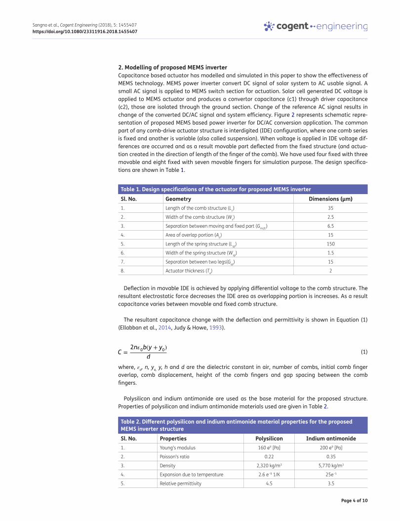
2. Modelling of proposed MEMS inverterCapacitance based actuator has modelled and simulated in this paper to show the effectiveness of MEMS technology. MEMS power inverter convert DC signal of solar system to AC usable signal. A small AC signal is applied to MEMS switch section for actuation. Solar cell generated DC voltage is applied to MEMS actuator and produces a convertor capacitance (c1) through driver capacitance (c2), those are isolated through the ground section. Change of the reference AC signal results in change of the converted DC/AC signal and system efficiency. Figure 2 represents schematic repre-sentation of proposed MEMS based power inverter for DC/AC conversion application. The common part of any comb-drive actuator structure is interdigited (IDE) configuration, where one comb series is fixed and another is variable (also called suspension). When voltage is applied in IDE voltage dif-ferences are occurred and as a result movable part deflected from the fixed structure (and actua-tion created in the direction of length of the finger of the comb). We have used four fixed with three movable and eight fixed with seven movable fingers for simulation purpose. The design specifica-tions are shown in Table 1.
Deflection in movable IDE is achieved by applying differential voltage to the comb structure. The resultant electrostatic force decreases the IDE area as overlapping portion is increases. As a result capacitance varies between movable and fixed comb structure.
The resultant capacitance change with the deflection and permittivity is shown in Equation (1) (Ellabban et al., 2014, Judy & Howe, 1993).
where, εo, n, yo, y, h and d are the dielectric constant in air, number of combs, initial comb finger overlap, comb displacement, height of the comb fingers and gap spacing between the comb fingers.
Polysilicon and indium antimonide are used as the base material for the proposed structure. Properties of polysilicon and indium antimonide materials used are given in Table 2.
(1)C =2n�
0b(y + y
0)
d
Table 1. Design specifications of the actuator for proposed MEMS inverterSl. No. Geometry Dimensions (μm) 1. Length of the comb structure (Lc) 35
2. Width of the comb structure (Wc) 2.5
3. Separation between moving and fixed part (Gmcfc) 6.5
4. Area of overlap portion (Ao) 15
5. Length of the spring structure (Lsp) 150
6. Width of the spring structure (Wsp) 1.5
7. Separation between two legs(Gsp) 15
8. Actuator thickness (Ta) 2
Table 2. Different polysilicon and indium antimonide material properties for the proposed MEMS inverter structureSl. No. Properties Polysilicon Indium antimonide1. Young’s modulus 160 e9 [Pa] 200 e9 [Pa]
2. Poisson’s ratio 0.22 0.35
3. Density 2,320 kg/m3 5,770 kg/m3
4. Expansion due to temperature 2.6 e−9 1/K 25e−5
5. Relative permittivity 4.5 3.5

Page 5 of 10
Sangno et al., Cogent Engineering (2018), 5: 1455407https://doi.org/10.1080/23311916.2018.1455407
The most well developed thermosetting polymers for structural use in micro systems are SU8 and indium-antimonide they both have excellent thermal and mechanical properties. Indium antimon-ide being a ductile material and having small elastic modulus which is 50 times smaller than Polysilicon it can tolerate large strains before fracture. For large displacement, low actuation voltage actuators it is a useful material as it is light in weight, highly flexible, excellent thermal stability and resistant to heat and chemicals. Figure 3 shows the step wise development of the proposed MEMS inverter structure.
3. Result and discussionElectrostatic transduction mechanism is being followed to perform mechanical movement of this proposed system. As the system has three main parts i.e. actuator (driver), mechanical resonator and converter parts. And actuation signal is provided by an external electrical AC signal of power grid to the driving part so as to drive (by the mechanical movement) the converter part. As per the sys-tem design, the upper set of fixed fingers is provided reference (actuating) voltage by a low DC bias voltage with AC perturbation, DC input terminal voltage (solar) is applied on the lower set of fixed comb fingers and connected in series with load. Whereas, the moving fingers with that of moving mass are grounded and all these inputs are given in Table 3.
Figure 3. Schematic diagram: (a) Clamp-Clamp beam actuator, (b) crab leg flexure, (c) folded flexure, (d) 8 crab leg structure.

Page 6 of 10
Sangno et al., Cogent Engineering (2018), 5: 1455407https://doi.org/10.1080/23311916.2018.1455407
Achieved different electrical and mechanical parameters for the four sets of variations are shown in Table 4.
Table 4. comparison of various parameters for different structure of actuatorParameter for silicon material Fixed-fixed Crab-leg Folded flexure Crab-6-legReference voltage (v) 390 180 120 190
Displacement (μm) 6.3 3 2.76 1.88
Capacitance (pf) 553 388 342 0.372
Force (n) 0.093 0.024 0.0076 0.0032
Table 5. Comparisons based on different design structures when polysilicon is used as materialSl. No. No. of comb 4 comb
(polysilicon)8 comb
(polysilicon)4 comb (indium
antimonide)
8 comb (indium
antimonide)1. Max voltage (v) 60 220 60 220
2. Displacement (μm) 5.7 8.02 4.95 7.53
3. Capacitance (μf) 1.52 1.72 1.27 1.56
4. Force (n) 0.12 0.9 0.07 0.6
Figure 4. (a) Surface displacement plot of 4 comb structure, (b) Surface potential plot of 4 comb Structure, (c) Surface displacement plot of 8 comb structure, (d) Surface potential plot of 8 comb structure.
Table 3. Specification of the input provided to the system designedSl. No. Input Value1. Reference DC voltage 23.3 V
2. Reference AC perturbed Voltage 220 V
3. Frequency 50–60 Hz
4. Solar DC input 24 V
Reference applied voltage, displacement, capacitance and force for four combs structure and eight combs structure with polysilicon and indium antimonide are shown in Table 5.
The most well developed thermosetting polymers for structural use in micro systems are SU8 and indium antimonide both have excellent thermal and mechanical properties. Indium antimonide be-ing a ductile material and having small elastic modulus which is 50 times smaller than Polysilicon it can tolerate large strains before fracture. For large displacement, low actuation voltage actuators

Page 7 of 10
Sangno et al., Cogent Engineering (2018), 5: 1455407https://doi.org/10.1080/23311916.2018.1455407
polyimide is a useful material as it is light in weight, highly flexible, excellent thermal stability and resistant to heat and chemicals. Figure 4 represents different simulation result of the proposed MEMS structure with four combs and eight combs structure. It is seen in Figure 4(b) and (d) that the surface potential is more at the moveable portion of the four comb structure.
Change of electromagnetic force and capacitance with input AC reference voltage is shown in Figure 5(a) and (b). Higher capacitance is achieved after increasing the combs number. But the dis-placement performance not changed that much. Figure 6(a) and (b) represents change of displace-ment with electric field for non-curved and curved structure. It is observed from the plot that in the second case, the values obtained for displacement (5.700252313 μm) and capacitance (1.76 nF) are much more than that of the first case (5.6170497 μm; 1.27 nF). The capacitance performances for curved and model are shown in Figure 7.
Figure 5. (a) Electrostatic force vs. input reference AC voltage (b) Capacitance vs. AC reference voltage.
Figure 6. Displacement plot of comb (a) without curvature, (b) with curvature.
Figure 7. Comparison of capacitance i.e. without curve (capacitance 1) and without curve (capacitance 2).

Page 8 of 10
Sangno et al., Cogent Engineering (2018), 5: 1455407https://doi.org/10.1080/23311916.2018.1455407
Again losses in MEMS Inverter can be calculated from Equation (2).
where F = Force (N), D = Displacement (μm), t = Simulation time (ms) = 24.5 ms for each simulation.
Hence, we got loss of about 0.3 mW for the model with the curvature (Figure 5(b)) which is very minimal as compare to the conventional DC/AC power inverter.
4. ConclusionIn summary, efficient MEMS based DC/AC converter is proposed with two different comb structures. Due to the curvature section in modified MEMS structure, electric filed lines increases as a result ef-fective capacitance increases for the same device area. So, for low input voltage a large deflection in MEMS comb structure has shown. As large deflection comb actuators employ large number of comb fingers and the increase in deflection and number of comb fingers facilitates the increment in electrostatic force which further results in increase of capacitance formed by the fixed and movable electrodes. So our proposed model is well acceptable model for the design of MEMS power inverter in which the driving fixed electrodes are actuated by DC voltage of 23.3 V with AC perturbation of 220. Comparisons between the various parameters of the two models are shown in Table 6.
Although losses in the Figure 5(b) the comb with curvature is more than that of without curvature at Figure 5(a) but we are getting better and desirable output than in case of the comb without curvature, however the losses is very much negligible in comparison with the conventional multilevel inverter.
FundingThe authors received no direct funding for this research.
Author detailsRalli Sangno1,2
E-mail: [email protected] ID: http://orcid.org/0000-0001-6220-8163R.K. Mehta2
E-mail: [email protected] ID: http://orcid.org/0000-0001-9995-977XSantanu Maity3
E-mail: [email protected] Electrical and Electronics Engineering, National Institute of
Technology, Yupia 971112, India.2 Electrical Engineering, North Eastern Regional Institute of
Science and Technology, Nirjuli, Arunachal Pradesh 791109, India.
3 Electronics and Communication Engineering, Tezpur University, Napaam, Tezpur, Sonitpur, Assam 784 028, India.
Citation informationCite this article as: Improvement in capacitive performances of efficient micro electro mechanical system (MEMS) based power inverter, Ralli Sangno, R.K. Mehta & Santanu Maity, Cogent Engineering (2018), 5: 1455407.
ErratumThis article was originally published with errors. Thisversion has been corrected. Please see Erratum (https://doi.org/10.1080/23311916.2018.1465152).
ReferencesBart, S. F., Lober, T. A., Howe, R. T., Lang, J. H., & Schlecht, M. F.
(1988). Design considerations for micromachined electric actuators. Sensors and Actuators, 14, 269–292. https://doi.org/10.1016/0250-6874(88)80074-X
Chakraborty, A., Kundu, A., Dhar, S., Maity, S., Chatterjee, S., & Gupta, B. (2011). Compact K-band distributed RF MEMS phase shifter based on high-speed switched capacitors. In 11th Mediterranean Microwave Symposium (MMS) (pp. 25–28). Hammamet: IEEE. doi:10.1109/MMS.2011.6068521
Choi, W. Y., Kam, H., Lee, D., Lai, J., & King, T.-J. (2007). Compact nano-electro-mechanical non-volatile memory (NEMory) for 3D integration. IEEE IEDM Technical Digest, 603–606.
Choudhury, A., & Maity, S. (2017). Design and fabrication of CSRR based tunable mechanically and electrically efficient band pass filter for K-band application. AEU - International Journal of Electronics and Communications, 72, 134–148. https://doi.org/10.1016/j.aeue.2016.11.021
Das, S., Kundu, A., Maity, S., Dhar, S., & Gupta, B. (2011). Novel
(2)L =F ⋅ d
t
Table 6. Comparison between the various parameters of the two modelsParameter Comb without curvature Comb with curvatureDisplacement 5.61705 μm 5.700252 μm
Capacitance 1.27 nF 1.76 nF
Electrostatic force 0.927 N 1.288866 N
Input reference 23.3 V 23.3 V
Losses 0.21 mW 0.3 mW

Page 9 of 10
Sangno et al., Cogent Engineering (2018), 5: 1455407https://doi.org/10.1080/23311916.2018.1455407
compact CPW filter for MICs using metamaterial structures. Mediterranean Microwave Symposium (MMS), 286–289.
Devi, N. M., & Maity, S. (2014). Metamaterial-based miniaturized CPW band stop filter design on silicon substrate for microwave applications. IEEE(IEEE EDS), ICCICCT2014, 171–174. doi:10.1109/ICCICCT.2014.6992950
Devi, N. M., Maity, S., Saha, R., & Metya, S. K. (2015). RF-MEMS and CSRRs based tunable filter designed for Ku and K bands application. Cogent Engineering, Taylor & Francis, 2, 1.
El-hawary, M. E. (2014). The smart grid – state-of-the-art and future trends. Electric Power Components and Systems, 42(3–4), 239–250. doi:10.1080/15325008.2013.868558
El-Katiri, L. (2014). A roadmap for renewable energy in the Middle East and North Africa. Oxford Institute for Energy Studies. ISBN 978-1-907555-90-9. https://doi.org/10.26889/9781907555909
Ellabban, O., Abu-Rub, H., & Blaabjerg, F. (2014). Renewable energy resources: Current status, future prospects and their enabling technology. Renewable & Sustainable Energy Reviews, 39, 748–764. https://doi.org/10.1016/j.rser.2014.07.113
Fréchette, L. G., Nagle, S. F., Ghodssi, R., Umans, S. D., Schmidt, M. A., & Lang, J. H. (2001). An electrostatic induction micromotor supported on gas-lubricated bearings. IEEE 14th International Micro Electro Mechanical Systems Conference (MEMS 2001), Interlaken, Switzerland.
Ghosh, S., Maity, S., Kundu, A., Chatterjee, S., & Saha, H. (2012). Thermal analysis of cantilever MEMS based low power microheater array for the selective detection of explosive and toxic gases. In 1st International Symposium on Physics and Technology of Sensors (ISPTS) (pp. 290–293). IEEE. doi:10.1109/ISPTS.2012.6260949
Han, C. H., Choi, D. H., & Yoon, J. B. (2011). Parallel-plate MEMS variable capacitor with superior linearity and large tuning ratio using a leverage structure. Journal of Microelectromechanical Systems, 20, 1345–1354. https://doi.org/10.1109/JMEMS.2011.2167657
Har, D., Yoon, E., & Hong, S. (2000). A low-voltage actuated micromachined microwave switch using torsion springs and leverage. IEEE Transactions on Microwave Theory and Techniques, 48, 2540–2545.
Hore, S., Maity, S., Sarma, J., G. Yadav, & Choudhury, A. (2015). RF MEMS based band-pass filter for K-band applications. 9th International Conference on Advanced Computing & Communication Technologies (2015 ICACCT TM), Springer, 52, 369–375. doi:10.1007/978-981-10-1023-1_37
Jeon, J., Pott, V., Kam, H., Nathanael, R., Alon, E., & King Liu, T. J. (2010). Seesaw relay logic and memory circuits. Journal of Microelectromechanical Systems, 19, 1012–1014. https://doi.org/10.1109/JMEMS.2010.2049826
Judy, M. W., & Howe, R. T. (1993). Polysilicon hollow beam resonator. Micro Electro Mechanical Systems, 1993, MEMS ‘93, Proceedings An Investigation of Micro Structures,
Sensors, Actuators, Machines and Systems (pp. 265–271). IEEE. University of California
Kundu, A., Das, S., Maity, S., Gupta, B., Lahiri, S. K., & Saha, H. (2012). A tunable band-stop filter using a metamaterial structure and MEMS bridges on a silicon substrate. Journal of Micromechanics and Microengineering, 22(045004), 12.
Legtenberg, R., Groeneveld, A. W., & Elwenspoek, M. (1996). Comb-drive actuators for large displacements. Journal of Micromechanics and Microengineering, 6, 320–329. https://doi.org/10.1088/0960-1317/6/3/004
Mondal, B., Maity, S., Das, S., Panda, D., Saha, H., & Kundu, A. (2015). Fabrication and packaging of MEMS based platform for hydrogen sensor using ZnO–SnO2 composites. Microsystem Technologies, 21, 146.
Nagle, S. F., & Lang, J. H. (1999). A micro-scale electric-induction machine for a micro gas turbine generator. Proceedings: Conference of the Electrostatics Society of America, Boston, MA, 57–66.
Receveur, R. A. M., Marxer, C. R., Woering, R., Larik, V. C. M., & de Rooij, N. F. (2005). Laterally moving bistable MEMS DC switch for biomedical applications. Journal of Microelectromechanical Systems, 14, 1089–1098. https://doi.org/10.1109/JMEMS.2005.851843
Saha, R., Maity, S., & Bhunia, C. T. (2016). Design and characterization of a tunable patch antenna loaded with capacitive MEMS switch using CSRRs structure on the patch. Alexandria Engineering Journal, 55(3), 2621–2630. https://doi.org/10.1016/j.aej.2016.05.002
Saha, R., Maity, S., Devi, N. M., & Bhunia, C. T. (2016). Analysis of pull-in-voltage and figure-of-merit of capacitive MEMS switch. Transactions on Electrical and Electronic Materials, 17(3), 129–133.
Saha, R., Sarkar, L., Maity, S. (2015). A novel MEMS based frequency tunable rectangular patch antenna. ICRCWIP2015, Springer, 339–345. doi:10.1007/978-81-322-2638-3_38
Sampsell, J. B. (1997). An overview of Texas Instruments digital micromirror device (DMD) and its application to projection displays. Proceeding of Society for Information Display International Symposium, 24, 1012–1015.
Shinjo, K., & Hirano, M. (1993). Dynamics of friction: Superlubric state. Surface Science, 283, 473. https://doi.org/10.1016/0039-6028(93)91022-H
Siwakoti, Y. P., Peng, F. Z., Blaabjerg, F., Loh, P. C., & Town, G. E. (2015). Impedance-source networks for electric power conversion part I: A topological review. IEEE Transactions on Power Electronics, 30(2), 699–716. https://doi.org/10.1109/TPEL.2014.2313746
Tilmans, H. A. C., & Legtenberg, R. (1994). Electrostatically driven vacuum-encapsulated polysilicon resonators: Part II— Theory and performance. Sensors and Actuators A: Physical, 45, 67–84. https://doi.org/10.1016/0924-4247(94)00813-2
Yao, J. J. (2000). RF MEMS from a device perspective. Journal of Micromechanics and Microengineering, 10, R9–R38. https://doi.org/10.1088/0960-1317/10/4/201

Page 10 of 10
Sangno et al., Cogent Engineering (2018), 5: 1455407https://doi.org/10.1080/23311916.2018.1455407
© 2018 The Author(s). This open access article is distributed under a Creative Commons Attribution (CC-BY) 4.0 license.You are free to: Share — copy and redistribute the material in any medium or format Adapt — remix, transform, and build upon the material for any purpose, even commercially.The licensor cannot revoke these freedoms as long as you follow the license terms.
Under the following terms:Attribution — You must give appropriate credit, provide a link to the license, and indicate if changes were made. You may do so in any reasonable manner, but not in any way that suggests the licensor endorses you or your use. No additional restrictions You may not apply legal terms or technological measures that legally restrict others from doing anything the license permits.
Cogent Engineering (ISSN: 2331-1916) is published by Cogent OA, part of Taylor & Francis Group. Publishing with Cogent OA ensures:• Immediate, universal access to your article on publication• High visibility and discoverability via the Cogent OA website as well as Taylor & Francis Online• Download and citation statistics for your article• Rapid online publication• Input from, and dialog with, expert editors and editorial boards• Retention of full copyright of your article• Guaranteed legacy preservation of your article• Discounts and waivers for authors in developing regionsSubmit your manuscript to a Cogent OA journal at www.CogentOA.com