incremental model synchronization in model driven ... · incremental model synchronization in model...
TRANSCRIPT

Incremental Model Synchronization in Model Driven
Development Environments
Ali Razavi1, Kostas Kontogiannis1,2, Chris Brealey3, Leho Nigul31University of Waterloo, {arazavi,kostas}@swen.uwaterloo.ca
2National Technical University of Athens, [email protected] Canada Lab, {cbrealey, lnigul}@ca.ibm.com
Abstract
Most modern model driven software devel-opment environments rely heavily on modeltransformations for generating various softwaredesign artifacts and eventually even sourcecode. However, during development, mainte-nance and evolution activities, these softwareartifacts are subject to updates and refactoringoperations. In such model driven developmentenvironments, these software artifacts need tobe re-synchronized every time one of them isaltered, so that they all remain consistent ac-cording to some specific rules, relations and do-main constraints. Until now, the standard ap-proach to model synchronization has been there-application of all transformation rules, aim-ing thus for the complete re-generation of allartifacts in all models involved. This completere-application is a safe yet computationally ex-pensive way to ensure consistency among mod-els. In this paper, we present a method forre-synchronizing software models in an incre-mental fashion by utilizing an indexing model.In this respect, using the proposed methodol-ogy, the time required for maintaining globalmodel consistency is proportional to the size
Copyright c© 2009 Ali Razavi, Kostas Kontogian-nis, IBM Canada Ltd. Permission to copy is herebygranted provided the original copyright notice is repro-duced in copies made.
of the changes and not that of the models in-volved. The proposed approach has been ap-plied for the incremental re-synchronization oflarge and complex models in the Eclipse WebTools Platform (WTP). Results indicate thatthis solution can significantly reduce the timerequired to re-synchronize models in such com-prehensive development environments as WTP.
1 Introduction
Throughout their life-cycle, software artifactsare constantly maintained and evolved. Theseartifacts specify different aspects of a softwareproject including requirements, architecture,design, and implementation, and therefore aresyntactically and semantically interdependent.These maintenance and evolution activities areapplied in an incremental way and in iterativeevolution cycles. As such, changes made to one,impact the others. Modern Integrated Devel-opment Environments (IDESs) aim to providea workspace in which these artifacts can beprogrammatically accessed and manipulated.In this respect, IDEs strive to provide facili-ties for transparent and effective propagationof changes across a diverse set of artifacts inthe workspace. These artifacts need to be syn-chronized when one or more of them is alteredso they all remain consistent according to spe-
216

cific rules, constraints and properties.Artifact synchronization for modern IDEs has
to be a fast and responsive process. Ideally,the users should be able to seamlessly reconcileall the dependent artifacts with the modifiedones. This requires the synchronization pro-cess to be incremental; meaning that the num-ber of changes that need to be made to bringthe artifacts into a consistent state should beproportional to the relative size of the changedelements and not the total size of the models.Most of the current tools equipped with modelsynchronization rely on non-incremental modeltransformation techniques which can be timeconsuming for large projects where many mod-els and artifacts are involved.
A so far neglected, yet imperative case ofmodel synchronization, deals with situationsin which two or more artifacts are generatedfrom one another by an existing model trans-formation. In this context, consistency rulesbetween these models are embedded and hid-den in the implementation logic of the modeltransformation rules themselves. More oftenthan not, these model transformations do notsupport bi-directional mappings; hence unableto reflect the modifications made to the tar-get artifacts back to the source artifacts. Sys-tematic and automated support for synchro-nization of models under such conditions uti-lizing a unidirectional model transformer canpotentially save a significant amount of effort,which, otherwise, would be required to reverse-engineer the logic of the generating transforma-tions, and re-implement these transformationsin a bi-directional and incremental framework.The solution to this problem becomes moreobscure for generative development processeswhich utilize multiple transformations to forma model driven software development chain.
In this paper we propose a novel method forincremental synchronization of software arti-facts when these artifacts are generated usingmodel driven generative development processesand environments. The proposed frameworktreats its subject transformation as a black-box. Therefore, other than assuming the trans-formations to possess some generic properties,the framework requires no detail knowledge ofthe transformation rules. Our proposed schemehas thus the advantage of saving the often toil-
some effort of re-implementing such transfor-mations in a new language or framework.
The following diagram illustrates the prob-lem of model synchronization in a more precisemanner.
MTGen ��
Δ1
��
N
Δ2
��M ′ TGen �� N ′
Δ1Sync �� Δ2
Let TGen be a collection of transformationsthat generate a target model N from sourcemodel M , and let Δ1 be a change operationon model M that yields M ′. Let’s also assumethat models M and N are synchronized, thatis, they are consistent according to some rela-tion, R. A simple approach to re-synchronizingM ′ and N is to re-apply all transformationsavailable in TGen on M ′ to obtain N ′. How-ever, when M is large enough relative to Δ1,and/or TGen is computationally expensive, thiscomplete re-generation approach will not be re-sponsive enough for modern interactive devel-opment environments. Furthermore, the com-plete regeneration of M ′ does not provide anymeans for reflecting the changes made to thetarget model, N ′, back to the source model,M ′. As the diagram depicts, a mapping suchas Sync could be used to generate from Δ1 asequence of change operations, Δ2, that is ap-plicable to N , and results in the same modelas N ′ = TGen(M ′) which is consistent with M ′
according to the same relation, R. We say thatSync is incremental, if the number of elementsin N that Δ2 modifies to obtain N ′ is minimal.
The architecture of our proposed solution isdepicted in the block-diagram diagram of Fig-ure 1. The crux of our idea is to store the mu-tual information for all inter-related models inone place, and refer to them by a unique iden-tifier across all the heterogeneous models in asystem. To achieve that, we devise a processcalled Conceptualization. This process involvesidentifying, abstracting, tagging and centraliz-ing the data encapsulated within a software ar-tifact into logical entities called Concepts. Re-lated artifacts share mutual information thatcan be linked by concepts. In other words, twoor more inter-related elements which reside indifferent artifacts can be made refer to the same
217

Conceptualizer
TransformationInput Artifact
Output Artifact
ConceptPool
Synchronizer
changes changes
Figure 1: Architecture of the SynchronizationFramework (arrows denote dataflow)
concept by referencing its unique identifier.Concepts are stored in a centralized location
referred to as Concept Pool. The frameworkprovides facilities to efficiently trace a conceptfrom any given position inside a model, to itscorresponding entity in the concept pool andvice versa. The synchronizer unit listens forchanges in the interrelated artifacts. When achange occurs, the system updates the values ofthe corresponding concepts in the concept pool.When the models need to be re-synchronized,the values in the affected concepts in the con-cept pool are propagated to the model elementsthat are indexed by the same unique identi-fier of the modified element. This propagationtakes the form of value replacement, and canbe carried out in linear time with respect tothe number of elements involved. As the fig-ure indicates, the synchronizer is able to prop-agate changes in both directions, notwithstand-ing the subject transformation’s support for bi-directionality or lack thereof.
The rest of this paper is organized as follows.A review of the related work is presented inSection 2. Section 3 presents the preliminaryinformation, establishes our used notation andterminology, and introduces our running exam-ple. The detail of the proposed methodologyis presented in Section 4. Section 5 discussesthe application of the proposed framework onEclipse Web Tools Platform (WTP) [16] andreports the results of our evaluations. Finally,Section 6 presents possible avenues for futurework, and concludes the paper.
2 Related Work
The major premise of our work is to avoidre-implementation of an existing transforma-
tion in another language or framework. Thissets an immediate diverging point between ourapproach and that of other incremental syn-chronization frameworks, majority of whichdefine some sort of specification mechanism,whereby an existing transformation has to bere-implemented. In contrast, we take thetransformation’s implementation as a black-box, and build the support for incremental syn-chronization around it, only assuming a fewgeneric properties about the transformation.
A catalogue of various model synchroniza-tion schemes is offered in [3]. The paper fo-cuses on formulating the external behavior ofmodel transformations. A general classifica-tion of model transformation frameworks canbe found in [7]. Two features that specifi-cally concern the problem of model synchro-nization are bi-directionality and incremental-ity. The paper introduces several frameworksthat support either or both of these features,most notable of which is the Object Manage-ment Group’s Query View and Transformation(QVT) [5]. QVT proposes the Relation andthe Core languages, both of which capable ofdenoting incremental and bi-direction transfor-mations with different expressiveness and com-plementary levels of abstraction.
Triple Graph Grammar (TGG) is a graphi-cal, declarative, incremental and bi-directionalmodel transformation methodology based ongraph transformation [14]. It has been advo-cated to be an effective foundation for tool inte-gration [2]. Beanbag is an emerging frameworkwhich offers a language that supports intra-relations between models [18]. Our conceptu-alization scheme also supports intra-relations.
Bi-directional transformations and their ap-plication in model synchronization have beeninvestigated by researchers in the programminglanguages community. Foster et al. proposedthe Harmony framework based on the notionof Lenses for bi-directional synchronization [8].They propose a language in which programs areinherently bi-directional. The Harmony frame-work has a state-based perspective on change.Contrariwise, Alanen and Porres have inves-tigated syntactic merging, differentiation andunion of structural models in [1] by adopting anoperational and compositional view of changes.
One solution that works with existing trans-
218

formations is SyncATL, proposed by Xiong etal. in [17]. They have extended the bytecode ofthe ATL virtual machine [4], whereby support-ing automated backward synchronization ofmodels linked by an ATL transformation. Forthe forward synchronization, SyncATL relieson re-invoking the transformation and mergingthe results with the existing target. The pro-posed technique, however, does not address in-cremental synchronization at all, as the frame-work relies on re-executing the transformationfor forward change propagation. The otherdrawback of this approach is its tight integra-tion with a specific technology, i.e. ATL.
Another framework with the theme of build-ing incremental synchronization around exist-ing transformation engines is presented in [12].This time the Tefkat transformation engine,which has logical programming flavor, is dec-orated with support for incrementality. InTefkat, transformation rules are specified aslogical predicates, and are performed usingSLD resolution. Their synchronization frame-work avoids redundant computation in succes-sive transformation of the same model by pre-serving the intermediate SLD trees. Anotherlogic based framework which exploits answerset programming for change propagation is pre-sented in [6].
In [15], Tratt articulates the spectra of chal-lenges involved in model driven tool integrationwith model transformations being their center-piece. The paper stresses the importance ofthe particularly challenging problem of changepropagation and enumerates the reasons forinadequacy of solutions based unilaterally oncommonly championed panaceas such as bidi-rectional transformations or traceability. Heconcludes that a comprehensive change prop-agation scheme, to be pragmatically effective,should function tractably over the most com-mon patterns of transformations.
The problem of incremental model synchro-nization parallels the extensively investigated,yet in some degrees open, problem of viewmaintenance in databases. Two noteworthyapproaches to this problem are presented in[9] and [11]. The view maintenance problem,along with the view update problem, have in-spired software engineers to look at interrelatedsoftware artifacts as essentially different views
of a common database. The bi-directionalityof synchronization can thus be remedied by so-lutions transpired for the view update prob-lem, and incremental synchronization becomesanalogous to view maintenance. In spite ofsimilarities, there are also key differences be-tween maintaining database views and syn-chronization of software models that warranta distinct research agenda dedicated to thelatter. Briefly, database views are defined infew, precise view definition languages, uponwhich the database community has come to aunanimous consensus. In comparison, modeltransformation frameworks are rather diverseand immature. Furthermore, the relationaldatabase model denotes flat structures. In con-trast, models comprise containment hierarchieswhich pose a semantic for deletion that can bepeculiar to handle using purely relational tech-niques.
Finally, CLIME [13] and MView [10] are con-straint based consistency management frame-works for incremental maintenance of softwareartifacts. These frameworks rely on the exis-tence of a well-defined set of constraints for en-suring the consistency of the interlinked mod-els, and are capable of incremental resolutionof inconsistencies for such cases.
3 Notations and Definitions
Automatic transformations are used in manysoftware development environments to gener-ate new artifacts from the existing ones. WebServices is one such domain that incorporatesvarious software specifications. For example,at the very core of Web Service models lies theweb service implementations coded in a pro-gramming language such as Java, and a ser-vice description denoted in an XML based for-mat called Web Services Description Language(WSDL). In this context, WSDL can be gener-ated from Java source code via a transforma-tion, as depicted in Figure 2. When an ele-ment of the source artifact, such as the nameof the method in this example, is updated, or amethod is added to the source code, the targetfile, e.g. WSDL in this case, has to be changedaccordingly. We will use this simplified versionof Java2WSDL transformation and its pertain-ing source and target artifacts of Figure 2 as
219

package test.dy.proj;public class SrvImpl {
public String method(String str) {return str;
}}
<wsdl:portType name="SrvImpl"><wsdl:operation name="method">
….</wsdl:operation></wsdl:portType>
AxisJava2WSDL
JavaSrvImpl.java
WSDLSrvImpl.wsdl
Figure 2: Generating WSDL from Java Classes
:Definition
:Types
method:Element
:ComplexType
str:Element
SrvImpl:PortType
method:Operation
Java2WSDLSrvImpl: Class
method: Method
str: Param
Figure 3: Abstract Models of Java and WSDL
our running example to demonstrate the vari-ous steps of our generic incremental model syn-chronization methodology.
In the running example, the source and tar-get models are respectively in Java and WSDLformats. To cope with this diversity, our pro-totype utilizes Eclipse Modeling Framework(EMF) to programmatically access the modelsin a unified environment. The abstracted mod-els of Java and WSDL artifacts of Figure 2 aredepicted in Figure 3. As shown, the abstractmodel of Java code encloses only on the parts ofthe original artifact that are pertinent for thecontext of the transformation. As a result, theinformation regarding the bodies of the meth-ods, such as variable definition or control flow,are discarded during abstraction.
For our purpose, model elements are in-stances of the types defined in a metamodelthat describes their constituting model. Theyare information bearing entities that encloseprimitive and complex information in their at-tributes. They can also have several containers,each containing other model elements. Modelelements can also reference other model ele-ments. The following definition captures theaforementioned characteristics.
Definition 1 Model element m is a tuple(C, A,R, T ), in which C is the list of containers,A is the list of attribute values, R is the list ofreferences, and T is the type of m. Each con-tainer Ci ∈ C is a list that comprises model el-ements of certain types. T is a set of mappingsto the elements of the metamodel that uniquelyascribe types to each fragment of m.
We use the same letters as function namesfor projection of individual components ofmodel elements, that is to say, m =(C(m), A(m),R(m), T (m)). It should be notedthat the names, types and constraints of the at-tributes and containers are all specified in themetamodel and not in the model element itself.This separation allows for type (and also name)agnostic manipulation of model elements. Us-ing this definition, the Java model of Figure 3is denoted as:
Class = (〈〈Method1〉〉, 〈”SrvImpl”, ”test.dy.proj”〉, ∅, Class)Method1 = (〈〈Param1〉〉, 〈”method”, ”String”〉, ∅, Method)Param1 = (∅, 〈”param”, ”String”〉, ∅, Param)
Definition 1 is recursive, since the members ofcontainment lists are assumed to be model el-ements themselves. Similar to model elements,models can also be denoted using Definition 1by simply assuming that they are the top levelelements of their containment hierarchy.
We use a compositional representation forchange in models, that is, every change op-eration is expressed as a composition of finergrained change operators. This requires identi-fying a number of atomic change operations asa starting point. We introduced three atomicchange operations that take part in changecomposition. Atomic changes, and compositechanges by extension, are defined as math-ematical functions. The notations used foreach of the atomic changes are listed as follows:
Table 1: Atomic change operationsSignature† Description� : M×T × (C ∪ N0) �→ M Insert Element� : M× (C ∪ N0) �→ M Delete Element� : M× (A ∪ N0) × Σ∗ �→ M Update Attribute† In the above signatures, M is the set of all model
elements, A is the set of all attributes, T is the setof all types and C is the set of all containers. Σ∗ isthe set of all valid attribute values.
The semantics of composition is also similarto that of mathematical functions. For exam-ple, the following composite change operationadds a new parameter to the method of theJava example, and then, updates its name to“param2”:
�(�(Method1, params,Param), name, ”param2”)
220

4 Incremental Synchronization
4.1 Conceptualization
Concepts are defined as primitive abstract en-tities that semantically associate two or moreinformation carrying elements across a pool ofheterogeneous software models. Models con-sist of model elements, which enclose severalattributes to represent information. A concept,however, can be even smaller than an attributevalue; attribute values can be composed of mul-tiple concepts. From this point of view, modelsprovide organization, structure and semanticsto an amalgamation of concepts by encapsulat-ing them into various model elements of differ-ent types.
Furthermore, related artifacts share mutualinformation. Conceptualization assists the syn-chronization of this mutual information in twomajor ways. First, concepts provide a sys-tematic way for tracing the propagation oftransformed data piecemeal, inside and out-side the boundaries of the artifact in whichthey are located. Second, concepts can es-tablish fine-grained interdependencies betweentwo or more inter-related artifacts; different el-ements in multiple artifacts can be forced torefer to the same concept by referencing itsunique identifier. Conceptualization is the pro-cess of extracting, indexing, tagging and cen-tralizing concepts. Concepts are stored in adatabase embedded in the development envi-ronment. This database is referred to as theConcept Pool.
For the case of the Java2WSDL example, thedependencies between the source and the tar-get of the transformation are established usingconcepts, as illustrated in Figure 4. Propagat-ing changes from one model to another in thisscheme takes the form of updating the perti-nent concepts in the concept pool followed byfetching the new values to each affected ele-ment, provided that there exists mechanismswhereby the system can pinpoint the relatedconcepts in the concept pool for a given modelelement. For example, in Figure 4, if themethod argument name “str” is changed in theJava model, the framework updates its relatedconcept in the pool and notifies its dependentelement in the WSDL side, i.e. WSDL message,
to updates its “name” attribute with the newvalue. A modification made to the elements ofthe target side can also be propagated to thesource side likewise.
4.2 Shadow Models
As mentioned earlier, it is essential to locatethe concepts associated with each model ele-ment, and also respond to queries about ele-ments sharing the same concepts. To enablethe latter, an index of identifiers of relatedmodel elements for each concept is stored inits corresponding entry in the concept pool.We propose Shadow Models, that is, intermedi-ate models intended to facilitate answering toqueries about elements sharing the same con-cepts. Shadow models closely mimic the struc-ture of the original models. They are, in fact,produced by exchanging the values of the iden-tified concepts in the models by their uniqueidentifiers. Shadow models make accessible theidentified concepts in the concept pool; e.g aconcept entry of an attribute value in the con-cept pool can be located by obtaining its con-cept ID from the exact same position of theattribute in the shadow model.
The algorithm for creating shadow modelsis listed below as Algorithm 1. In the algo-rithm, the value of the model elements thatcontain a recognized concept are replaced bythe identifier of said concept. An importantpractical note when generating unique conceptidentifiers is to ensure that they are still valididentifiers with respect to the grammar of boththe source and the target artifacts. For thecase of Java, this means that they need tobe constructed using the characters allowed inthe Java grammar and the WSDL schema forclass and method names and also WSDL iden-tifiers. This requirement is to guarantee thatthe Shadow model is a valid artifact of the sametype of the original one, and can be used as in-put to transformers.
The de-Shadow operation, listed in Algo-rithm 2, performs the opposite operation of theShadow algorithm. That is, it scans throughthe shadow artifacts, extracts the patterns forconcept IDs from the attributes of model ele-ments (an attribute can contain more than oneconcept by means of concatenation), it fetches
221

yyXR2SÊ6GÖaö32xf3qË
AFed2R2SŠöaè32xrq2D3
Figure 4: Conceptualization of Java and WSDL models
Algorithm 1 Shadow(M)Require: Model M = (C, A,R, T ) and
Concept-Pool CPEnsure: Shadow Model S1: S ← Clone(M)2: for all m ∈ S do3: for all ai ∈ A(m) do4: �(m, i, CP.getConceptID(ai))5: end for6: end for7: return S
the values of the found concept IDs from theconcept pool, and replaces the IDs with thevalues.
Algorithm 2 de-Shadow(S)Require: Shadow Model S = (C, A,R, T ) and
Concept-Pool CPEnsure: de-Shadowed Model M1: M ← Clone(S)2: for all s contained in M do3: for all ai ∈ A(s) do4: id[1..n] ← matchConceptID(ai)5: v ← ai
6: for j ← 1 to n do7: cv ← CP.getConceptV al(id[j])8: v ← replace(v, id[j], cv)9: end for
10: �(s, i, v)11: end for12: end for13: return M
Figure 5: Shadow/Transform/de-Shadow Pipeline
We insist that shadow artifacts be valid doc-uments of the same type of the source model,because we use them as inputs to the trans-formation to generate shadow models of thetarget domain, thereby achieving traceabilitythrough the common concepts appearing inboth shadow models. Figure 5 shows the out-line of the process of creating target modelsusing shadow artifacts.
4.3 Synchronization Process
The idea of propagating model dependenciesusing shadow models relies on the presump-tion that, under the course of the transforma-tion, the unique concept IDs in the shadowartifact are not subject to manipulations thatmake them unrecognizable in the resulting tar-get shadow model. In other words, the essenceof transformations for which this methodol-ogy is applicable is re-organization of concepts.Therefore, the attribute values of model ele-ments should only be subject to a category ofre-writing operations that do not dismantle the
222

concept IDs. For example, the transformationsare allowed to concatenate two concept values,or add a prefix (or a suffix) to a concept. Op-erations such as shuffling the characters of aconcept, cutting some of the letters or anythingelse that does not preserve the concept IDs arenot directly permitted. This, however, is not amajor limitation for two reasons. On the onehand, concepts are defined to be the most prim-itive and finest grained pieces of information ina model. With that perspective, a wide rangeof meaningful transformations are expected tosimply re-organize these quanta of informationinto different encapsulating data types, ratherthan tearing them apart. On the other hand,it is possible to work around these limitations.In Section 6 we discuss the outlines of an ex-tension to the framework that allows anomalycases of string re-write operations.
As a result of Conceptualization and exploit-ing Shadow models, we can ensure that thesource of a model transformation and its prod-uct, the target artifact, are entangled recipro-cally using their mutual concepts. These con-cepts are stored in the central concept poolalong with other concepts in the system, andeach is individually and uniquely identifiableby a universal ID. When one of the attributesof any of the objects belonging to either thesource or the target artifact is subjected to anupdate value modification, essentially the valueof one or more concepts that constitute thevalue of that particular attribute are updatedin the concept pool. The affected concepts arealso tagged as modified and the time-stamp ofthe latest change is also recorded in the corre-sponding entry of those concepts in the conceptpool. Two strategies are conceivable for prop-agating the values of updated concepts to theother artifacts that carry those concepts. Thefirst strategy is to disseminate the changes toall the artifacts which incorporate the affectedconcepts. This needs maintaining a list of ref-erencing artifacts for each concept entry in theconcept pool. The second strategy for the syn-chronization to be carried on lazily, meaningthat synchronization is invoked for each arti-fact, only when it is opened or it is focused bythe user. The outline of the synchronizationprocess that is composed of three Phases, islisted below.
Change Propagation Process1 Phase A: Conceptualization2 Create Models from Artifacts3 Extract Model Concepts4 Store concepts in Concept Pool5 Create Shadow Models
6 Phase B: Artifact Generation7 Generate Artifact from source Shadows8 de-Shadow the generated shadow artifact
9 Phase C: Change propagation10 Upon Change in Source or Target:11 Update related concepts in Concept Pool12 For all modified concepts13 Get the locations of all referencing elements14 If synchronization strategy is immediate15 push the changes to all impacted elements16 else17 monitor accessing the affected models18 push the changes when they are opened
In the first phase of the process above, weset the stage for incremental model synchro-nization by abstracting the involved softwareartifacts as EMF compliant models, creatingunique IDs for the concepts, and compilingshadow models. In the second phase of theprocess, we execute the artifact generations onthe created shadow models, thereby obtainingthe shadow model for the target artifacts. Sub-sequently, we run the de-Shadow algorithm toconvert the target shadow to the desired targetartifact. Finally, the third phase of the pro-cess applies the framework whenever a changeoperation in one model creates the need of re-synchronizing with the rest. The frameworktraces the modified elements to their conceptentries in the concept pool, and updates thepertinent values there.
Figure 6 illustrates synchronization ofthe Java2WSDL example utilizing theShadow/Transform/de-Shadow process. Onthe top of Figure 6, lies the Java source code,which is the input artifact of the Java2WSDLtransformation. The Shadow operation,depicted as an arrow of the same name,encapsulates the following operations in theorder given: First, abstraction of the Java codeinto the model format (Figure 3). Second,Conceptualization of the resulting model.Third, performing Algorithm 1 on the abstractmodel. Finally, serializing back the resultingshadow model into the Java code format. Theresult is the shadow code, which, as portrayedin the figure, is structurally identical with theoriginal code in the segments that are relevantto the transformation, save the values of the
223

Axis Java2WSDL
_@jmwmclname : Concept
value = SrvImplrefID = _@jmwmclnameP1 = Java:/Package/Class/nameP2 = WSDL:/Definition/PortType/name
__cidb__rGDasQ6LÀO6w__cide__
__cidb__rGDasQ6LÀO6w__cide__
deShadow
C tidb GGDGG Q6LÀÀL O6 id
package test.dy.proj ;public class __cidb__rGDasQ6LÀO6w__cide__ {
public String __ cidb__rGDqgn6LÀO6w__cide__ (String __cidb__rGgjYnEdLÀO6w__cide__ ) {return null ;
}}
package test.dy.proj ;public class SrvImpl {
public String method (String param) {return param;
}}Shadow
hadow
<wsdl:portType name “__cidb__rGDasQ6LÀO6w__cide__ "><wsdl:operation name=" __cidb__rGDqgn6LÀO6w__cide__ ">
….</wsdl:operation>
</wsdl:portType>
<wsdl:portType name ="SrvImpl"><wsdl:operationname ="method">
….</wsdl:operation>
</wsdl:portType>
Figure 6: Synchronization by Shadow
concepts which are replaced by their uniqueidentifiers. Specifically for this transformation,the bodies of the methods are ignored by thetransformation, hence no manifestation in theabstract models, and consequently, neither inthe shadow code.
The shadow code is used as the input toJava2WSDL, whereby yielding the shadowWSDL. To obtain the target model, Algo-rithm 2 is run over the target shadow, as il-lustrated in Figure 6 as the de-Shadow arrow.Any two related elements in either sides of thetransformation, e.g. the name of the Java classand that of the WSDL portType, refer to thesame entity in the concept pool and thus havethe same value, inasmuch as the concept IDsobtained by looking at the same locations ofthese elements in their shadows are identical.
It should be noted that the update synchro-nization aided by concepts and shadow mod-els is two-way, even if the original transforma-tion is unidirectional. This is one of the majorbenefits of the proposed approach. The syn-chronization engine only exploits the artifacts,their shadows and the implicit correspondencesdenoted in the concept pool. No further invo-cation of the original artifact generator is re-
quired in this process. There is no distinctionbetween the source and target of the transfor-mation after it is applied initially. It is there-fore possible that the target of the originaltransformation becomes the source of modelsynchronization, i.e. the updates that need tobe propagated are made to the model whichwas the product of the transformation. Theoverall process of synchronization using con-cepts and shadow models is listed in the follow-ing. The system allows two possible synchro-nization strategies. The first strategy is classi-fied as direct, that is, the framework pushes allchanges to all impacted models as the changeshappen. The second strategy is classified aslazy, that is, the models are left inconsistent,and the invalidated elements are updated fromthe concept pool, whenever they are accessedfor the first time or when there is an explicitrequest for re-synchronization.
A special case that deserves further attentionis when an updated attribute carries more thanone concept. It can be represented by concate-nation of conceptualized values and prefixes (orsimilarly suffixes). For example an attributecan comprise a fixed prefix, the first name, ahyphen–which is another invariant segment–
224

and the last name of a person. The firstname and the last name are the conceptualizedand variable segments of the attribute value,whereas the title and the hyphen are constant.When the value of such attribute is updated,the system should sort out the concepts thatare modified and extract the new segmentalvalues corresponding to those concepts. To de-tect the altered concepts, the attribute value isscreened against its counterpart in the shadowmodel. The fixed segments appear in both se-quences and are used for aligning concept IDsand their segmental values.
4.4 Propagation of Insertion
Unlike Update operations, Insertion and Dele-tion operations are structure altering changes.Propagation of insertion and deletion inducedchanges for an arbitrary model transformationcan be multifaceted and complex. This com-plexity can fortunately be addressed by assum-ing that the transformation has certain proper-ties, namely, continuity and monotonicity. Theformer is to guarantee that the transformationis not sensitive to any particular instance modelin its domain, but rather it transforms them alluniformly. The latter requires the change op-erations to have similar effects on both sides.These two properties seem to be valid for awide range of model transformations used inpractice..
Model elements, according to Definition 1,have containers, which can be inter-dependentacross multiple models. In other words, thedependency of element types can be viewedas dependency between the containers of thosetypes. This interpretation of dependency linksimplicitly requires that insertion of an elementto one container (only) result in addition of el-ements in its inter-dependent containers. Weassume that, Insertion (and similarly Deletion)homogeneously results in Insertion (and respec-tively Deletion) type of changes in other inter-related containers. We refer to this propertyof transformations as monotonicity. If inser-tion of an element results in update or deletiontype of changes in the target model, then thetransformation is non-monotonic.
Furthermore, we assume that inducing an ele-ment into a container follows a uniform pattern
of insertions that is independent to the numberof elements inside said container. For example,addition of the third parameter to a methoddoes not trigger a different pattern of changesin its inter-dependent containers, than does theaddition of the second parameter for that mat-ter. We call this property of transformationscontinuity and such transformations are calledcontinuous.
Although these two assumptions may seemtoo restraining, in practice they are in compli-ance with the majority of artifact generators.In fact, the space of transformations that com-mon relational frameworks such as QVT, TGG,Tefkat etc. are capable of expressing are alsocontinuous and, for the most part, monotonic.The explicit definitions of the transformationrules that happen to violate either of these twoassumptions have to be known. The proposedframework allows for extension points insidethe concept pool for incorporating such rules,so as to achieve complete synchronization.
The proposed methodology for the propa-gation of Insertion involves deliberately in-jecting each container in the shadow modelwith a dummy placeholder element called aμ-template. These template-injected shadowmodels are thereafter used as input to the ar-tifact generation process, and, as a result, theμ-templates will be transformed and instanti-ated as target artifacts.
More specifically, using μ-templates, the tar-get artifact is generated with an additionalhypothetical new element. When an actualinsertion change to a container takes place,the added element replaces the available μ-template in the container. In other words, thisμ-template is consumed into an actual elementin the source artifact and a new unsubstanti-ated μ-template is inserted to accommodate fu-ture insertions.
In other words, in this process we a priori as-sume the possibility of having an additional el-ement to be inserted in the future for each con-tainer, and reserve in advance an appropriatestructure and space (i.e. the μ-template) forsuch elements in the container. When needed,we use these reserved places for adding a newelement to the containers they reside in, by up-dating the values of their attributes and render-ing them as visible.
225

µInject
SrvImpl: Class
method: Method
str: Param
µ:Method
µ:Param
µ:Param
SrvImpl: Class
method: Method
str: Param
Figure 7: Injecting μ-templates
Consuming the reserved space of μ-templatesprohibits the opportunity for adding more el-ements to the container in the future; sim-ply because each container only had one extraspace. Therefore, to continue supporting inser-tion of new elements into the container, it isimportant to create a new reserved space be-fore consuming the available μ-template. Thesecond assumption enables us to provide a newμ-template by simply duplicating the old oneand assigning new concepts to it and so on.
To better demonstrate how Insertion inducedchanges can be propagated by utilizing μ-templates, we proceed with the example sce-nario of synchronizing an insertion of a methodargument to the Java side with its correspond-ing WSDL model. The process is illustratedin Figures 7, 8, 9 and 10. The first stepof the process is injecting μ-templates into thecontainers of the source artifact. To disguisethis amalgamation from the user and make thesynchronization as transparent as possible, μ-templates are in fact injected into the Shadowmodels right after their creation. Shadow mod-els, as discussed, closely mirror the structure ofan artifact and are hidden from the user. Fig-ure 7 shows (the shadow of) an abstracted Javacode for a web service on the right hand side.On the left, the same Java model is shown afterit is populated by μ-templates. As the figure il-lustrates using dashed lines, in every containerin the model, an extra element is injected.
As stated previously, the shadow of the sourceartifact, instead of the artifact itself, is used togenerate the target artifact. The same stepsare essentially involved for synchronizing In-sertion changes, with the addition of inject-ing the source shadow model with μ-templates.Figure 8 shows the shadow model of the Java
Java2WSDL
µ:Element
µ:Element
µ:ComplexTypes
µ:Element
µ:Operation
SrvImpl: Class
method: Method
str: Param
µ:Method
µ:Param
µ:Param
:Definition
:Types
method:Element
:ComplexType
str:Element
SrvImpl:PortType
method:Operation
Figure 8: Transformation of μ-templates
abstraction populated with μ-templates, andits resulting WSDL model which includes μ-templates in several places. μ-templates arediscerned from normal elements by having allthe concepts they encapsulate marked as μ-template in the concept pool. In other words,any model element that hosts a μ-templateconcept is a μ-template, and therefore, shallnot have a manifestation in the target model.This requires a slightly different de-Shadow al-gorithm to check and skip over elements thatcontain concepts flagged as μ-template.
When an element is inserted in one of thecontainers of the source artifact, the first stepis to conceptualize the new element, i.e. ex-tracting the concepts that appear in the newmodel element. This is realized by consumingthe μ-template that had been provided for in-sertion of new elements in the container. Theμ-template is turned into a normal element byessentially removing the μ-template flags fromall its concepts’ entries in the concept pool.When consumed, μ-template concepts’ IDs re-main intact. The synchronization framework,when encounters such concepts in other mod-els, deduces that they belong to the consumedμ-template concepts. The container of the con-sumed μ-templates need to be populated bynew μ-templates to allow for further insertionof model elements. Therefore a new μ-templateis created and injected into the container. Fig-ure 9 illustrates the steps involved during in-sertion of a new element dubbed as consuminga μ-template.
In order to synchronize the target model withthe modified source model, the de-Shadoweris reapplied on the target shadow model. Asmentioned, the μ-template concepts were con-
226

Duplicating a µ-Template
SrvImpl: Class
method: Method
str: Param
µ:Method
µ:Param
µ:Paramarg2:
Param
SrvImpl: Class
method: Method
str: Param
µ:Method
µ:Param
µ:Paramµ:
Param
SrvImpl: Class
method: Method
str: Param
µ:Method
µ:Param
µ:Param
Consuming a µ-Template
to add a param
Concept Pool
arg2str µ
Concept Pool
str µ
Concept Pool
str µ µ
Figure 9: μ-template Consumption
µ:Element
µ:Element
µ:ComplexTypes
µ:Element
µ:Operation
:Definition
:Types
method:Element
:ComplexType
str:Element
SrvImpl:PortType
method:Operation
µ:Element
µ:Element
µ:ComplexTypes
µ:Element
µ:Operation
:Definition
:Types
method:Element
:ComplexType
str:Element
SrvImpl:PortType
method:Operation
arg2:Element
Concept Pool
arg2str µ
Concept Pool
arg2str µ
Figure 10: Propagating Insertion
verted to normal elements in the concept poolat consumption time, i.e. when the sourcemodel was subjected to insertion. Therefore,the de-Shadower, when reinvoked over the tar-get shadow model, would no longer discardthese elements and will render them in the out-put model, as demonstrated in Figure 10. Sim-ilarly to the source model, a new μ-templateneeds to be placed in the container to enablefurther insertion of elements in it. Unlike thesource model, providing a new μ-element to thetarget model involves a few more steps thansimply duplicating the former μ-element andadding brand new concepts to it. In particu-lar, the dependency links between the new μ-template and the one that was just insertedin the source model have to be established bymaking them reference the same concepts. Toachieve that, we need to find out the conceptIDs that are assigned to the newly created μ-template in the source model, when the old μ-template was consumed. As usual, our mediumfor communicating such information is the con-cept pool. Therefore, this can be enabled byproviding pointers in the entries of consumedμ-template concepts in the concept pool to thenew concepts created for the new μ-template.For example, in Figure 9, when the μ-templateis consumed and its value is updated to “arg2”in the concept pool, it points to the concept as-sociated with the newly created μ-template in
its container. The target side is only aware ofthe consumed μ-templates’ IDs, since the newones were not present in the model at the timeof transformation. However, the de-Shadow al-gorithm follows these pointers for each conceptto reach the new μ-template’s concept IDs.
Using μ-templates, we have reduced the prob-lem of propagating Insertion to an alreadysolved problem of propagating Update.
4.5 Propagation of Deletion
Deletion is handled simply by hiding model ele-ments whose concepts are tagged with the spe-cial flag deleted in the concept pool. For exam-ple, when the parameter of a method is deletedfrom the source code, all the concepts of its cor-responding element in its abstract model aretagged as deleted in the concept pool. Whensynchronization is carried out on other models,the framework simply conceals the elements,any of whose concepts are flagged as deleted inthe concept pool.
When considering containment, propagatingdeletion changes raises some ontological issues.More specifically, we need to recognize theexistential causality relationships between themodel elements in order to properly identify theelements that have to be purged as a result of adeletion change. The semantics of containmentrelationship provides useful guidelines for such
227
reasoning. Briefly, deletion of a containmentresults in purging all its contained elementsand, consequently, their constituting concepts.When performing inter-model change propaga-tion, all the elements whose any concepts areflagged as deleted will be flagged as deleted like-wise.
5 Experiments and Evaluation
For the evaluation of the proposed framework,we have designed a prototype which we ap-plied it for the incremental synchronizationof models in the Eclipse Web Tools Platform(WTP). WTP encompasses several types ofsoftware artifacts each having different for-mat and schema. Furthermore, it extensivelyuses transformations for converting these ar-tifacts to one another. One such transforma-tion, which we have used throughout this pa-per for presentation, and also for conductingour assessments, is Java2WSDL. Java code isa textual file that is parsed into an AbstractSyntax Tree (AST), and is compiled into abinary class file. In contrast, WSDL is anXML document that conforms to the WSDLschema, which is specified in the XML schemaformat. Moreover, because of its extensibilitytype definitions, which are XML schema ele-ments, the type definition part of WSDL con-forms to XML Schema for XML Schema (themeta-meta-model of XML).
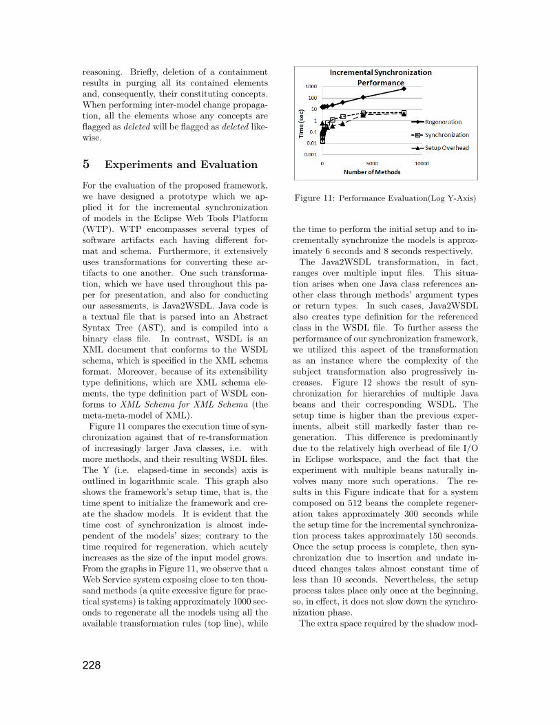
Figure 11 compares the execution time of syn-chronization against that of re-transformationof increasingly larger Java classes, i.e. withmore methods, and their resulting WSDL files.The Y (i.e. elapsed-time in seconds) axis isoutlined in logarithmic scale. This graph alsoshows the framework’s setup time, that is, thetime spent to initialize the framework and cre-ate the shadow models. It is evident that thetime cost of synchronization is almost inde-pendent of the models’ sizes; contrary to thetime required for regeneration, which acutelyincreases as the size of the input model grows.From the graphs in Figure 11, we observe that aWeb Service system exposing close to ten thou-sand methods (a quite excessive figure for prac-tical systems) is taking approximately 1000 sec-onds to regenerate all the models using all theavailable transformation rules (top line), while
Figure 11: Performance Evaluation(Log Y-Axis)
the time to perform the initial setup and to in-crementally synchronize the models is approx-imately 6 seconds and 8 seconds respectively.
The Java2WSDL transformation, in fact,ranges over multiple input files. This situa-tion arises when one Java class references an-other class through methods’ argument typesor return types. In such cases, Java2WSDLalso creates type definition for the referencedclass in the WSDL file. To further assess theperformance of our synchronization framework,we utilized this aspect of the transformationas an instance where the complexity of thesubject transformation also progressively in-creases. Figure 12 shows the result of syn-chronization for hierarchies of multiple Javabeans and their corresponding WSDL. Thesetup time is higher than the previous exper-iments, albeit still markedly faster than re-generation. This difference is predominantlydue to the relatively high overhead of file I/Oin Eclipse workspace, and the fact that theexperiment with multiple beans naturally in-volves many more such operations. The re-sults in this Figure indicate that for a systemcomposed on 512 beans the complete regener-ation takes approximately 300 seconds whilethe setup time for the incremental synchroniza-tion process takes approximately 150 seconds.Once the setup process is complete, then syn-chronization due to insertion and undate in-duced changes takes almost constant time ofless than 10 seconds. Nevertheless, the setupprocess takes place only once at the beginning,so, in effect, it does not slow down the synchro-nization phase.
The extra space required by the shadow mod-
228

Figure 12: Performance for multiple beans
Figure 13: Shadow files space overhead
els is reported in Figure 13. As the figure de-picts, the space overhead of shadow models andμ-templates tends to be on the same order ofmagnitude of the size of the models, hence itdoes not pose any limitations on the system.
6 Conclusion and Future work
In this paper, we propose a novel method forincremental synchronization of software arti-facts. Our technique differs from the previousundertakings primarily in the fact that it usesthe original artifact generators as black boxes.As such, other than some generic assump-tions about the type of the transformations, itneeds no detailed knowledge of the consistencyrules. In contrast to the approaches based onincremental transformation engines, our pro-posed model synchronization framework nei-ther needs denotation of transformations in anew language, nor it requires the transforma-tions to be re-executed after they are used forthe initial creation of the target models. Theframework even when used in conjunction with
unidirectional artifact generators, is capable ofpropagating updates in the opposite directionof that of the used artifact generator. Thesynchronization scheme results in models thatcomply with the original transformation.
The proposed approach is based on a pro-cess we refer to as Conceptualization. Thisprocess extracts the mutual information of twoor more inter-related artifacts and stores themin a central concept pool. Shadow Models areused as input to the transformations for provid-ing effective traceability between concepts andmodel elements in interlinked models. We uti-lize the technique to provide instant and incre-mental propagation of Update induced changesbetween models. To support incremental syn-chronization of Insertion induced changes, wealso propose the notion of μ-templates, somelocalized place holders in the shadow models.
Treating transformations as black-boxes hasthe advantage of eliminating the cost associ-ated with reverse engineering of consistencyrules between software artifacts. However, theproposed solution, even though covering a widespectrum of practical model transformations,is limited by the concept preservation assump-tion made for the case of update changes, andalso by continuity and monotonicity assump-tions made for insertion propagation. The ideaof concept pool is nonetheless extensible. In ad-dition to plain values, concepts can be allowedto assume embedded rules defined in an exten-sion language for explicit denotation of conceptdependencies inside the concept pool. For agiven transformation, we partition its domaininto segments that comply with the assump-tions, as well as singularity areas that need spe-cial treatment. We can leverage such embed-ded rules to also automate the synchronizationof the singularity areas in the transformation’sdomain along side the regular segments. Weare currently integrating this extension into theframework.
Further improvements to the conceptu-alization process can be achieved throughautomated meta-model comprehension. Weplan to utilize knowledge representationtechniques such as formal concept analysis toenhance that stage of our framework, and toapply the framework for the re-synchronizationof software models in Integrated Development
229

Environments such as RSA.
AcknowledgementThis work is supported by an IBM Center forAdvanced Studies Fellowship.
References
[1] M. Alanen and I. Porres. Difference andunion of models. UML 2003 PROCEED-INGS, pp. 2–17, 2003.
[2] C. Amelunxen, F. Klar, A. Konigs, T.Rotschke, and A. Schurr. Metamodel-based tool integration with MOFLON.In 30th Int. Conf. on Software Engineer-ing (ICSE’08), pp. 807–810, Leipzig, Ger-many, May 2008.
[3] M. Antkiewicz and K. Czarnecki. De-sign space of heterogeneous synchroniza-tion. In R. Lammel and J. Visser, editors,GTTSE’07, LNCS. Springer, 2008.
[4] ATL. Specification of the ATL VirtualMachine version 0.1. LINA and INRIA,Nantes, France, 2005.
[5] MOF QVT final adopted specifi-cation, Nov 2005. OMG documentptc/05-11-01.
[6] A. Cicchetti, D. Di Ruscio, and R. Eramo.Towards propagation of changes by modelapproximations. In EDOCW ’06: Enterp.Dist. Object Computing Conf. Worksh.,page 24, Washington DC, USA, 2006.
[7] K. Czarnecki and S. Helsen. Feature-based survey of model transformation ap-proaches. IBM Systems Journal, 45(3):621– 45, 2006/07/.
[8] J. N. Foster, M. B. Greenwald, J. T.Moore, B. C. Pierce, and A. Schmitt.Combinators for bidirectional tree trans-formations: A linguistic approach to theview-update problem. ACM Trans. Pro-gram. Lang. Syst., 29(3):17, 2007.
[9] T. Griffin and L. Libkin. Incrementalmaintenance of views with duplicates. pp.328 –, San Jose, CA, USA, 1995.
[10] J. Grundy, J. Hosking, and W.B. Mu-gridge. Inconsistency management formultiple-view software development envi-ronments. IEEE Transactions on Soft-ware Engingeering (TSE), 24(11):960 – 81,1998/11/.
[11] A. Gupta, I. S. Mumick, and V.S. Sub-rahmanian. Maintaining views incremen-tally. volume 22, pp. 157 – 166, Washing-ton, DC, USA, 1993.
[12] D. Hearnden, M. Lawley, and K. Ray-mond. Incremental model transformationfor the evolution of model-driven systems.volume 4199 LNCS, pp. 321 – 335, Gen-ova, Italy, 2006.
[13] S.P. Reiss. Incremental maintenance ofsoftware artifacts. IEEE Transactions onSoftware Engineering (TSE), 32(9):682 –97, Sept. 2006.
[14] A. Schurr. Specification of graph transla-tors with triple graph grammars. volume903 of LNCS, pp. 151–163, Herrsching,Germany, June 1994.
[15] L. Tratt. Model transformations and toolintegration. Journal of Software and Sys-tems Modeling, 4(2):112–122, May 2005.
[16] Eclipse Webtools Platform Projecthttp://www.eclipse.org/webtools/
[17] Y. Xiong, D. Liu, Z. Hu, H. Zhao, M.Takeichi and H. Mei. Towards automaticmodel synchronization from model trans-formations. In ASE’07: Proceedings 22ndconf. on Automated Software Engineering,pp. 164–173, New York, 2007.
[18] Z. Hu, M. Takeichi, H. Song, H.Mei, Y. Xiong, H. Zhao. Bean-bag: Operation-based synchronizationwith intra-relations. Technical ReportGRACE-TR-2008-04, Tokyo, Japan.
230