india technical catalogue - gmgr
TRANSCRIPT

India Technical Catalogue


PAM Cast iron - 1
SAINT-GOBAIN PAM –GLOBALLY 1ST CHOICE FOR CAST IRON DRAINAGE SYSTEMS.
l High strength / Durability over time
l Non-combustible / No smoke hazard
l Silent in operation / Excellent acoustics
l Fast & Easy installation – Fit & Forget
l Easy to repair – Modular + taking rodding knocks
l Excellent aesthetics & finish
l Stable + No deterioration with age
l 100% recyclable / sustainable / green
Sales Arguments
Sect
ion
1

Why choose SAINT-GOBAIN PAM cast iron pipe systems ?
As a leading manufacturer and the world’s top-ranking exporter of cast iron pipe systems for building application, SAINT-GOBAIN PAM is an essential partner for designers of waste water and rainwater drainage systems.
The SAINT-GOBAIN PAM cast iron products are safe, easy to install and efficiently meet the requirements of project engineers.
Waste water and rainwater drainage systems are like the arteries of buildings, calling for strong and long lasting material, so that their lifespan is at least the same as the buildings expected life.
Watertight, non combustible and silent in operation PAM cast iron allows specifiers to design safe and reliable drainage systems.
Combining unrivalled longevity and minimal maintenance, PAM cast iron spigot systems are definitely the first choice to maintain a sustainable and comfortable environment as required in your building projects.
Advantages of Cast Iron
CI remains as the best material for
waste water applications in view
of its durability over time, ease of
maintenance, non combustible
nature and significantly better
mechanical properties including
acoustics.
PAM system has been designed to
overcome most of the problems
faced with old generation CI
waste water pipes used in India
such as corrosion resistance,
aesthetics, ease in installation and
compatibility with plastics.
Wide range of products and complete system offering
Global experience and track record is a key enabler for this.
Products meet EN 877 standards which covers the full system
Systems for connecting other materials (plastics) to PAM pipes
Technical and sales support
Well trained team – PAM India and distributors
Logistics support
Stocks are now available in India for most of the fast moving range
2 - PAM Cast iron

Components
Saint-Gobain PAM pipes and fittings are of hubless design which are lighter and easy to install and maintain. They are designed for optimal safety, reliability and long service life.
Joints
The hubless pipe systems are connected by mechanical metal coupling which are equipped with elastomer gasket ensuring flexible assembly with excellent water tightness.
To meet specific requirements for pressure resistance, grip collars or self anchoring coupling are also available to lock these couplings.
Connectors to other materials
Recognising the need for using different pipe and fitting materials based on installation criticality and economics, Saint-Gobain PAM also offers solutions for connection of PAM cast iron to other materials such as PVC, HDPE, PP, Steel, etc. There are also solutions for connecting to rigid pipes of old designs which are commonly encountered in projects involving renewal of old installations.
Coatings
The durability of cast iron systems has been demonstrated over more than a century of history. The purpose of the coatings is to protect cast iron products against corrosion in order to further increase their service life. Saint-Gobain PAM has conducted extensive research on coatings and continuously works towards improving their performance.
Spun pipes and cast iron fittings and accessories are provided with –- External coating to withstand aggressive
environments (climate effect + ground conditions in case of buried pipes)
- Inner linings to withstand thermal and chemical stresses from the effluents drained.
PAM Cast iron - 3
Comprehensive Product Range
Consistency
The principle adopted for a given product range is to offer consistent performance for pipes, fittings and accessories without any weak points, i.e. all the components of the pipe system provide the same level of performance in withstanding the constraints in each specific field of use.

Shot blasting RinsingRinsing Hot phosphate process
Rinsing CoolingCataphoresis Oven drying 180 °C
4 - PAM Cast iron
Building waste water drainage systems - grey and black water- must be able to withstand all types of normal domestic effluents.
In recent years, following changes have been noticed in the types of these fluids: - Higher concentration of household detergents, - Use of more aggressive hygiene products, - Rise in operating temperatures.
The demands on sanitary drainage systems are constantly increasing. SAINT-GOBAIN PAM coatings have been adapted to meet those constraints.
Ability to transport effluents
Resistance to domestic fluids:
Basic inner lining for pipes The standard inner lining for PAM pipes is a sound, adherent epoxy resin which prevents the fluid transported from coming into contact with the metal.
The composition of the epoxy coating is controlled to minimise porosity, and its homogeneity is monitored in real time.
The smoothness of this coating increases flow rate and limits head losses.
Basic coating for fittings and accessories
The common coating for fittings is an epoxy resin deposited through an cataphoresis process. However other processes like fluidised powder coating can be used to meet specific requirements.
The average thickness of standard coatings for fittings can vary from 70 μm to 150 μm, according to the targeted performance.
Engineered for end use – Normal Applications
Cataphoresis, Fittings and accessories are coated with an epoxy resin deposited by cataphoresis which ensures a uniform deposit and excellent covering of edges. The optimised process by SAINT-GOBAIN PAM is based on a careful shot-blasting and entails interposing a chemical surface treatment during the coating cycle, between rinsing after shot-blasting and the cataphoresis bath in order to enhance the coating’s covering power.
At the end of the cycle, the parts are oven-dried to complete the reticulation of the epoxy film.
Substantial improvements in:
- the epoxy film’s adhesion to the cast iron,
- the corrosion resistance of the coated cast iron. FOCUS
ENSIGN®S

PAM Cast iron - 5
Resistance to corrosive or/and hot effluentsThe inside of cast iron systems can be subjected to chemical and thermal aggressions when they transport fluids that are corrosive and/or at high temperatures. Superior inner lining for pipes: two-part epoxy resin applied in two layers to obtain a film with no porosity.
Resistance to aggressive backfills or severe climatic stressesThe outside of a pipe may also be subjected to the aggressive effects of climate or backfills, in the case of buried systems. External anticorrosion coating for pipes
Zinc coating for pipe protection by galvanic effect.
Solutions for intense stresses on fittings and accessoriesAccording to the principle of continuity with no weak points, coatings for hollow components must withstand the same stresses as pipes. There is an anticorrosion coating process for these parts to face major stresses, due to the fluids transported or to the environment.
For more than 100 years of testing and market research, SAINT GOBAIN PAM has built up great expertise in cast iron. Increasingly effective coatings have been developed to keep pace with the changing utilisations and requirements.
Superior coating for fittings and accessories: epoxy powder coating in fluid bed.A thick anticorrosion coating to guarantee long service life for products.
Preheated parts are moved through a tank containing epoxy powder in suspension, to be coated. They are then stove dried to ensure perfect reticulation of the polymerised epoxy film. Perfect control of both temperature and immersion time determines the coating thickness: 300 μm in average.
Zinc metallization The zinc metallization is an active protection provided by the galvanic action of a zinc/iron cell.
Twofold action:
• Formation of a stable protective layer of insoluble zinc salts,
• Self-healing of any damage.
Zinc metallization is an excellent corrosion inhibitor and is extremely effective in extending the lifespan of products submitted to backfills or climatic stresses.
Tests carried out by the SAINT-GOBAIN PAM Research Centre: two identical notches are made on samples before immersing them in a highly corrosive medium.
Without zinc protection Corrosion beyond notch
With zinc protection Zinc salts on notch
FOCUS
© N
orm
an P
ogso
n - F
otol
ia.c
om©
Oliv
ier -
Fot
olia
.com
Engineered for end use – Aggressive ApplicationsENSIGN®PLUS

6 - PAM Cast iron
Recommended ranges for these applicationsS ranges equipped with EPDM gaskets are fully adapted to fit all the constraints involved in the above-mentioned uses.
S – Systems: complete ranges of cast iron pipes & fittings and their gaskets.
ENSIGN spigot range: diameters from DN 50 to DN 600
For common domestic use For conventional grey water, black water and rainwater applications, For systems installed above ground, in ducts, raft foundations or included into concrete.
To provide clearer guidance on the chemical resistance of S range in domestic applications, SAINT-GOBAIN PAM has carried out 20 additional tests to the EN 877 Standard requirements on detergent products (floor cleaning product, laundry detergents…) and special products (stain remover, drain cleaner…) of common use.
The tests were carried out on samples, under the temperature of use recommended by the manufacturers and where it was relevant, up to 70°C since hot water is normally supplied in dwellings around 50 – 60°C.
After stopping the test, the pipes and fittings shall be washed immediately to eliminate any stains and the coatings shall be examined with regard to blistering and rusting both according to ISO 4628-2 and 3. (Accepted levels according EN 877)
The duration of the test is considered equivalent to the extrapolation of a real chemical stress undergone during 7 or 10 years (a 10 to 15 min stress per day). This test method however simulates a severe stress since the samples lies in direct contact with the solution, the temperature is being maintained and the test includes no rinsing over its duration.
Dilution* pH 23° 50° 65° 70°Test
(Days)SALT WATER * Same as sea water 30g/lDETERGENTS 28
Laundry detergents Phosphate free wash 2ml / l 7.7 28Softener 2ml/l 7.6 28
Dish washer detergents Washing tablet 3g/l 9.3 28Washing gel 3g/l 9.8 28
Washing up liquid 2ml/l 7.65 not applicable 28Stain remover Type “ACE GENTLE” 7.7 28
COMBINATION Wash + stain remover 2ml/l + 3ml/l 7.7 28Wash + Softener 2 ml + 3ml/l 7.7 28
CLEANING PRODUCTS Floor cleaning product 8ml/l 8.2 not applicable 28
Bleach 8ml/l 8.25 not applicable 28WC CLEANERS Toilet bowl cleaner (gel) 20ml/l 5.45
not applicable28
Drain cleaner gel 0,33 ml/l 13 4Liquid descaler 80ml/l 2.07 28
* according to the manufacturer
S ranges and EPDM gaskets
ENSIGN®S
Pipes Basic external coating
Recommendations – ENSIGN®SResistance to conventional domestic fluids, in compliance with EN 877
Fittings and accessoriescataphoresis coating, red brown colour
Grey water, black water and rainwater
Basic external primer paint:Acrylic paint, red brown colour
Dry film average thickness: 40µmBasic inner lining:
Two part epoxy resin ochre colourDry film average thickness: 130µm in one layer

PAM Cast iron - 7© N
orm
an P
ogso
n - F
otol
ia.c
om
ENSIGN®PLUS
Pipes Inner lining: two part epoxy resin ochre colour. Two layers for a lining with no porosity.Dry film average thickness: 250µm in two layers.
Thick polymerised epoxy powder coa-ting, grey colourDry film average thickness: 300µm.
Fittings and accessories
Recommendations ENSIGN®PLUS Resistance to aggressive and/or hot effluents
Above and below ground waste water drainage for aggressive discharge.Aggressive effluents are characterized by: Their content (acids, bases, solvents, hydrocarbons…), their combinations and their temperature. Owing to its anti-corrosion thick linings, the Plus range provides a greater chemical resistance and is particularly well adapted for intense uses.
Hot water resistance: 24 h at 95°C continuous and thermal cycles (1500 cycles of 5 min between 15° and 93° C)
Salt spray resistance: 1500 h Chemical resistance: 1 < pH < 13
For intense/professional use
Compulsory use of PLUS range+ EPDM gasketAcids and bases, saline solutions common temperatures of use
pH 20°C 60°C 80°CWATER Salt water NaCl 30g/l 5.6
Demineralised water, Waste water 6.6-6.9DETERGENTS 7.4-10SPOT REMOVER, OXIDANTS 4.2-10.3MINERAL ACIDS
Hydrochloric HCl 5%, Sulphuric H2S04 10% 1Sulphuric H2SO4 1% 2Phosphoric H3PO4 10% 1.3Phosphoric H3PO4 5% 1.8Phosphoric H3PO4 2,5% 2Nitric HNO3 10% 2
ORGANIC ACIDSLactic 1%-10% 1.1-2.2Citric 5% 2Vinegar 10%-30% 2.9-3.2
BASESSoda NaOH 12Soda NaOH 13.6Ammonia NH3, Potash KOH 12.1-13.6Bleach 10%-100% 12-12.5
SALTS KCL3%, NaH2PO4 3%, (NH4)2SO4 3% 4.2-6.7SOLVENTS (except Acetone)
Ethanol, Methanol, Glycol, Xylene –White Spirit, Gasoline, Diesel, Petroleum –Lubricants, Petroleum derivates –
High temperatures OILS –
For non described or intense industrial uses, please contact usIn the application table above, light green means S range still possible, heavy green means Plus range compulsory.
This being two-dimensional, the boarder between S and Plus ranges is only determined by the type of the fluids and the operating temperature. But the selection of the appropriate range is also directly related to the duration of daily exposure, the reason why we called this chapter intense of professional use.
The combination of high pH products (base and alcaline products) and high temperatures systematically calls for the use of the Plus range.

8 - PAM Cast iron
Robustness and mechanical strengthPipe system components must withstand hazards before they reach the job site such as accidental impact before and during installation, during storage, handling and transit. In service, outdoor exposed pipes may be damaged by accidental impacts or vandalism. To avoid breakages, which can be expensive, or minor stress cracks which can have serious consequences in operation, the choice of material should be carefully considered.
Impact strength and crush resistance Cast iron is well-known for its robustness. The quality of PAM products is ensured by careful control of both metal composition and manufacturing process.
The spinning of pipes in the De Lavaud process, followed by heat treatment, gives these products outstanding mechanical properties.
Key mechanical characteristics required by the standard EN 877 are controlled by three tests, carried out on pipes when coming out of the heat treatment furnace to assess tensile strength, ring crush resistance and hardness.
In addition, operators have opted to maintain a further test which gives a good indication of the quality of heat treatment: the guillotine impact test.
The pipes Saint Gobain PAM process Others EN 8777 requirements
Tensile Strength on samples in MPa (average value) 300 270 200 min.
Ring Crush Strength in MPa (average value, DN 100 pipes) 450 360 350 min.
Brinnell Surface Hardness in HB degree (average value) 220 245 260 max.
These results indicate greater resistance to impacts and crushing, easier machining and cutting. This also means the products are easier to install on job sites.
De Lavaud process In this process, a constant flow of molten metal at perfectly controlled temperature and composition is gradually input into a steel mould rotating at high speed. The mould external wall is cooled by circulating water and the evenly distributed molten metal cools on contact with the wall before extraction.
The process is characterised by a quick cooling that gives a finer solidification matrix and thus a more homogeneous metallurgical structure.
Heat treatmentThe spun pipes are placed and rotated in a heat treatment furnace at 950°C and then gradually cooled again. This step is essential to the process as it transforms the cast iron’s metallurgical structure. The reduction of iron carbides and the increase of ferrite content considerably improve the mechanical properties of cast iron and reduce its surface hardness. The graphite of the cast iron resulting from the SAINT-GOBAIN PAM process forms clustered graphite, halfway between lamellar and ductile iron.
FOCUS

PAM Cast iron - 9
Thermal expansion of plasticsTo allow expansion without damaging the drainage network, plastic pipe systems demand specific accessories – expansion collars or joints, brackets allowing axial movement, in general one out of two.
If these precautions were not taken, expansion could be absorbed by the pipework and cause distortion.
Cast iron can do without these expensive accessories. It makes the design work easier and decreases the risk of mistakes at installation stage.
These properties of cast iron pipe systems are also valuable for engineering structures such as bridges where important expansions have to be carefully addressed to secure the construction project.
Thermal expansion coefficient of cast iron and other materialsThe thermal expansion coefficient for cast iron – 0.01 mm/m/°C – is very low and very similar to that of steel and concrete; the building and the pipe systems will move and will expand together.
For cast iron, the bracketing system is designed to only carry the weight of the pipe and its content, which makes the designers work easier. (See our recommendations in the Specifier’s Manual p 54).
Plastic pipes, for themselves, expand considerably with increasing temperature. Their bracketing system must be designed and adapted accordingly, as it can deeply affect the stability of a pipework and its performance over time.
Resistance to thermal expansionMost solids expand when they are heated and are liable to elongate under temperature increase.
For pipe systems made of materials that are subjected to high levels of thermal expansion, precautions have to be taken at design stage.
Cast iron which expands very little does not require specific bracketing nor expansion collars. It makes the specifers’ design work easier and avoids extra cost at installation stage.
Thermal expansion of cast iron and other materials for 10m and a temperature rise of 50°C.
Thermal expansion coefficient
0,0104 mm/°C.m �5,2 mm
0,07 mm/°C.m �35 mm
0,150 mm/°C.m �75 mm
0,02 mm/°C.m �100 mm
Cast iron
PVC
PP
HDPE
7 times more
14 times more
19 times more
??

10 - PAM Cast iron
Water tightness over timeFailure of water tightness can occur on drainage systems in operation. They are then due to breaks, misalignments, crushes or cracks…
Long-lasting water tightness depends on two main factors:
• No deterioration of pipes:Cast iron is highly resistant to ovality. Their specified mechanical properties and their stability enable cast iron systems to withstand operating stresses extremely well.
• No deterioration of assemblies:Elastomers are carefully selected for the long-term stability of their physico chemical characteristics to ensure the lasting water tightness of the rubber gaskets.
Water tightness of cast iron systemsCast iron is a dense and non-porous material. Cast iron pipe systems are water tight and impervious.
Cast iron components, straight and rigid are assembled using metal couplings fitted with elastomer gaskets which ensure that the system is completely water tight.
Assemblies benefit from a conventional approach. Made with only simple tools, they allow installation tolerance with no risk of leakage.
This ease of installation ensures that the specified performance is always obtained, even in adverse conditions - unlike for plastics when either gluing or welding can be affected by installation hazards (ambient conditions such as temperature or damp) or when personnel with special skills are required.
Water tightness and maintenanceSometimes blockages occur in drainage networks; the pipework materials must be resistant so that the maintenance is easy.
The S and Plus systems can resist without damage all normal maintenance processes including high-pressure jetting. They have been submitted to a high pressure test according to the Swiss standard SN 592 012.
Sanitary drainage systems, whether exposed or not, must remain water tight over time. Any defects can cause serious damage, leakages, dripping or slow permeation and generate costly repairs, and disruption.
SAINT-GOBAIN PAM cast iron mechanical assemblies are designed to reach easily instant water tightness and are not dependent on process control (gluing or welding…)
Water tightness
Robustness and dimensional stability of cast iron components along with the careful selection of elastomer ensure pipe installations give high performance and long service life.
The S and Plus ranges, being assembled and anchored, have successfully passed a high-pressure jetting test: cleaning pressure of 120 bar from the pump, which means 100 bar at the nozzle outlet, without leakage or misalignment.

Internal overpressure in drainage networks rarely occurs and is always accidental. Thrust efforts in the overloaded sections have to be addressed to guarantee both water tightness and mechanical stability.
As the robust cast iron components can address any pressure hazard, then the couplings will be submitted to the strain.
The quality of the couplings and their careful selection according to their field of use will prevent misalignment or disconnection of the pipework.
Internal pressure resistance
Specific points of the pipe work: Resistance to end thrust efforts
Some specific points on a pipe system may be subjected to thrust loads due to changes of direction or gradient, especially branches and plugs. To avoid any risk of disconnection or slippage of the pipe components, these efforts must be addressed and the sections at risk must be anchored:
The section of pipe has to be held between two fixed points, by using stack supports, for example.
And a self- anchoring coupling or an ordinary coupling anchored with a grip collar shall be used.
For full installation details, see the Technical specification section.
FOCUS
High-pressure mechanical couplings:
In some rare cases, a waste water drainage system may pass through a number of storeys without any outlet and there could be a risk of overloading (blockage due to operation or saturation of the sewer main).
The pressure resistance required to ensure that these systems remain leaktight and stable in such cases depends on the height of the water column liable to occur and calls for high-pressure couplings able to withstand the resulting pressure (up to 10 bars).
See p 48 in the Specifier’s Manual section.
Standard pressure mechanical couplings:
Waste water drainage systems – which differ from rainwater drainage systems as regards pressure – are connected to sanitary appliances installed on each storey which may serve as outlets in case of accidental overloading (due to blockages, for example).
The pressures that occur cannot therefore exceed the pressure corresponding to the height of one storey, i.e. about 0.3 bar.
The couplings we describe as ”standard” are perfectly suitable for this common type of application.
Resistance of the couplings to hydrostatic pressure
PAM Cast iron - 11© m
init
chii
- Fot
olia
.com

12 - PAM Cast iron
As components that are integrated in buildings, waste water and rainwater drainage systems must remain in a serviceable condition over the long term in spite of adverse operating conditions.
Ageing refers to any gradual, irreversible change in a material’s structure and/or composition, liable to affect its behaviour or serviceability.
When a material is selected, the stability of its properties ensures operational reliability over time.
Ageing behaviour
Stability of cast iron mechanical propertiesThe ageing of a material may be due to its own instability, to environment or chemical stresses, to mechanical strains, or a combination of any of those causes.
It is an established fact that cast iron offers long service, owing in particular to the stability of its mechanical properties over time.
- Cast iron is not sensitive to thermal ageing
•Its mechanical strength remains stable.
• Its thermal expansion is very low compared to plastics.
• Cast iron pipe systems are not liable to creep at operating temperatures.
- Cast iron does not deform under mechanical strain
• Its ring stiffness (cold measurement) around 700 kN.m is not affected by temperature and is 87 times that of PVC pipes. It is mainly appreciated for buried pipework.
• Its longitudinal stiffness, which eases bracketing and protects water stream in horizontal sections, remains intact. Its Young modulus of elasticity is ranking from 80 to 120 GPa vs 2 to 5 GPa for PVC.
• Cast iron’s tensile strength is 8 times that of PVC: 200 MPa vs 25. (residual resistance, after 50 years according to the standards). This property is of utmost importance in case of network overloading.
The properties of cast iron ensure the stability of systems and long lasting operational safety.
Resistance to climatic stressesThe properties of materials are extremely important when they are stored or exposed to adverse conditions (extended
exposure to ultraviolet light or wide temperature variations…).
Cast iron undergoes no structure modification under climatic stresses.
Ageing of polymers:Deterioration of mechanical properties under temperature stress.
Under temperature effect plastics can suffer two kinds of deteriorations, including at operation temperatures:
- Creeping is an irreversible elongation under the combined action of both temperature and an important mechanical strain. Plastic pipe system like PVC or HDPE are particularly sensitive; in horizontal sections, they can bend between two support brackets under their own weight.
- Modification of the elastic limit: most plastic materials will soften under temperature increase. Under temperature decrease on the contrary, they crystallize. PVC for example become rigid and may crack under mechanical strain – their operating temperature range is generally between -20°C to 80°C, but depending on their nature, the range can be much narrower.
Photochemical ageing
Depending on their nature, climatic stresses (such as solar radiation, damp or heat) will cause more or less severe photochemical ageing to plastic materials.
They can just alter their surface finish, but also deeply modify their mechanical properties and then adversely affect their serviceability.
The same can happen through slow chemical attack by solvents or even in aqueous media.
FOCUS

European standards
International standards
Cast iron pipes and fittings, their joints and accessories for the evacuation of water from buildings. Requirements, test methods and quality assurance
EN 877/A1
Cast iron drainage pipes and fittings (spigot) ISO 6594
Elastomeric seals - Material requirements EN 681-1 ISO 4633
Requirements for a quality management system design, product development, production, installation and after sales support
ISO 9001
Environmental management systemRequirements with guidance for use
ISO 14001
Testing standards
Fire testsFire classification of construction products and building elements.Classification using data from reaction to fire tests
EN 13501
Reaction to fire tests for building products - Part 1 Building products excluding floorings exposed to the thermal attack by a single burning item
EN 13823
Measurement of noiseLaboratory measurement of noise from waste water installations
EN 14366
PAM Cast iron - 13
In particular, it lays down requirements regarding: - Reaction to fire (product range), - Resistance to internal pressure, - Dimensional tolerances, - Tensile strength, crushing strength, - Joints and their leaktightness, - Inner lining and external coatings and
their suitability.
It also defines test methods and the quality management system. EN 877 is a self-declared standard; the manufacturer is allowed to self declare that his product complies with this standard.
Only compliance with EN 877 that is validated by a third party for all criteria and periodically tested can guarantee the performance of the systems you specify.
The quality of the SMU / ENSIGN S, SMU / ENSIGN Plus, product ranges are guaranteed by the following marks of approval: BBA, Kitemark and/or Marque NF.
Quality Management SystemThe plants which manufacture our products are certified for their compliance with the ISO 9001 standard which specifies requirements for a quality management system. The scope of this standard covers product design and development and the quality control of procurements, training, and administrative follow-up.
Products performancesPAM pipe systems comply with European standard EN 877, applicable to a system (cast iron pipes and fittings, couplings and accessories for building drainage). This standard, specifying the technical requirements for cast iron products, is the most demanding in the market.
Compliance with standards and quality marks
??

14 - PAM Cast iron
For fire safety in a building, the major responsibility rests with the project manager who must respect the Regulation in force. In buildings at risk like multi storey buildings, materials with reduced flammability should be selected to apply precautionary principle. The following two concepts are applied as regards fire safety: Reaction to fire and fire resistance.
Fire safetyProtect people and property
Reaction to fire It is the instant behaviour when a fire breaks out, its propensity to ignite or feed a fire. This behaviour is assessed on the basis of standardised tests and described in an EUROCLASS classification.
Reaction to fire for PAM cast iron systemsFor drainage systems, safety in case of fire is the only essential safety requirement.
For cast iron systems, the tests and technical specifications are defined in the amended standard EN 877, and the
section ”Reaction to fire” alone requires a mandatory certificate, issued by an independent laboratory, to obtain CE marking.
Cast iron as a material itself is classified as A1 in the Euroclass classification for reaction to fire.
In tests carried out by the CSTB accredited laboratory, the SAINT-GOBAIN PAM cast iron ranges (pipes, fittings and accessories including elastomer gaskets and coatings) received the following excellent Euroclass ranking:
A2 -s1, d0For smoke emission and the production of flaming droplets, the SAINT-GOBAIN PAM products respectively achieved the highest possible rating: s1 et d0.
EUROCLASS classification is based on harmonised test methods and defines a reaction to fire ranking so to make it possible to compare construction products.
A1 and A2 are reserved for products that are not, or only slightly, combustible.
So, cast iron remains one of the safest drainage material for fire safety.
SAINT GOBAIN PAM cast iron ranges comply in every respect to the standard EN 877. This compliance is validated by complete Quality Marks, is periodically tested by accredited third part laboratories and brings you the performance guarantee for the systems you specify.
marking The mandatory CE marking is required by the European Construction Products Directive (DPC 89/406/CEE) and must be affixed to products before allowed pass into the European market.
• To ensure their free movement within the European Union and the EEA.
• To ensure those products do not constitute a hazard for the occupants or users of buildings.
• To implement the same safety criteria throughout Europe it is referred to Essential requirements concerning public health, safety and consumer protection.
The CE marking on products certifies that they comply with the harmonised part of their reference standards.
FOCUS
14 - PAM Cast iron

PAM Cast iron - 15
Many buildings are not protected enough against fire hazards. It means that fire can spread rapidly, can destroy the building and the properties in a few hours and jeopardize the occupants’ lives.
When a fire breaks out, the first objective is to slow down its spreading both horizontally and vertically.
Drainage systems must be selected so that they resist the passage of fire and do not feed it.
Fire resistance It is a construction component’s ability to withstand fire for a given period of time and to retain its serviceability in the event of fire.
If a fire breaks out, it is essential to prevent any early collapse of the structure, and then to limit the extent of the damage so as to ensure that occupants can be evacuated and/or the belongings will be protected.
Waste water drainage systems and fire stopping requirementsDrainage systems passing through structures designed to withstand fire, should not provide open breaches. For a given time, specified in the applicable Regulations, they should not allow the passage of fire, smokes, heat or combustion products from one compartment to the other.
For plastics, the fire-stopping rule consists in ”plugging the hole”. This function is ensured by the fire collars recommended by the manufacturers. Plastic materials which are highly sensitive to heat will not withstand the fire, will not remain in place, even in the case of a contained fire.
As shown by laboratory tests, if the fire collars are not activated or do not operate correctly, and depending on the type of plastic material, the greatest hazard is posed by combustion products (flaming droplets) or smokes.*
SAINT-GOBAIN PAM’s solutionsSAINT GOBAIN PAM cast iron, non-combustible material has a melting point over 1000°C.
In most cases it requires no additional fire protection.
SAINT-GOBAIN PAM carried out a non-exhaustive series of tests on its cast iron pipe systems in order to offer precise guidance for fire resistance. For most configurations, exist protections made of mineral wool.
With the active fireproof solution PAM-Protect combined with a fireproof mortar to seal wall and slab penetrations, PAM cast iron pipe systems proved to meet integrity and insulation requirements up to 240 minutes (4 hours)*.
Complete report available on request.
SAINT-GOBAIN cast iron is non-combustible, it does not feed the fire, nor gives off either gases or smokes liable to delay fire fighters or damage other equipment. * Furnace tests carried out in 2011-2012 according to
EN 1366 -3 at the EFECTIS testing centre, the European leader in fire science, engineering, tests, inspection and certification
Compartmental principle Fire Safety Regulation for buildings, when it exists is based on compartmental principle.
Within a building, a compartment is a fire rated space designed to stop the fire for a given period of time. The fire-stopping requirement for walls (shells and slabs) is generally 2 hours or less – and exceptionally 4 hours.
The requirement depends on the nature of the building and its level of occupancy, and can be very different from one country to another.
FOCUS
© G
auti
er W
illau
me
- Fot
olia
.com
Heat
Flames
Flammable gas
Limited
Temperature
National Building Code, India 2005
Load
Compartmentation: Clause C-9‘‘The building shall be suitably compartmentalized so that the fire and smoke remain confined to the area where the incident has occurred and does not spread to the other part of the building.”ANNEX B (Clause 3.8 and 3.14)High Rise Buildings – 15 m in height +
B-1.8.1 : Specifically mentions...‘‘Care shall be taken to ensure that the construction of the drain pipe does not allow spread of fire/smoke from floor to floor.”

16 - PAM Cast iron
Noise in buildings is considered to be detrimental to health and the quality of life. Efforts have been made, in the last 30 years, to attenuate the sounds coming from the street, worsening the perception of the sounds emitted within the buildings. Heat insulation policies aiming at reducing energy consumption will also heighten these perceptions.
Among the priority criteria in the comparative performances of drainage materials, acoustic performance is reckoned to be second only to fire safety: cast iron pipe systems have intrinsic acoustic properties. Owing to the development in accessories equipment, they offer outstanding performances.
Acoustics
Pipe systems and equipment noiseNoise from waste water pipe systems is classified under the regulation in the “equipment noises”.
Noise originating from pipe systems is due to the sound energy produced by water/air turbulence, but mostly by the mechanical effect of the water-flow on the internal pipe walls.
Acoustics and SAINT-GOBAIN PAM cast iron pipe systemsAirborne noiseWhen a material is dense and thick, the pipe walls prevent air transmission; as is the case with cast iron which offers intrinsic acoustic properties.
Structure-borne noiseWhen the noise produced in a pipe is not transmitted by the air, the residual noise is transmitted by structural vibrations.
Whilst the mass of the cast iron limits the vibratory level, the junctions and fixing to the building will propagate noise. Objective: Dampen the vibrations at the connections with the solid structure.
Noise and regulations requirementsNoise is an energy affecting air pressure and is transmitted through vibration.
Sound is measured in decibels (dB) using a nonlinear scale.
For noise from equipment apparels, the following categories are identified and measured:
•Airborne noise: air vibrations that are propagated
In the case of waste water pipe systems, this noise is mainly heard in the room where the pipe is located.
•Structure-borne noise: vibration of a building’s structure
This noise will be noticed in rooms adjacent to the pipe.
Statutory requirements on ”equipment noise” for structure-borne noise differentiate between noisy rooms and quiet rooms with sound-attenuation requirements. For noisy rooms the noise level requirements is generally 35 dB or more. For quiet rooms, which are generally living, resting rooms and work rooms, the noise level requirements are generally around 30 dB, in cases where noise regulations exist.
FOCUS
Acoustic comfort is a differentiation criterion that indicates construction quality. The building project manager and the specifier may define together specific requirements to improve the final construction.

PAM Cast iron - 17
SAINT-GOBAIN PAM’s solutionsVibrations transmitted to the building structure are dampened by installing “sound absorbers” and by combining:
- couplings equipped with elastomer sealing gaskets which reduce metal to metal contact and prevent the transmission of vibrations.
- if required, rubber lined insulating brackets or acoustic dampeners, and stack supports equipped with elastomer gaskets.
In 2008, SAINT-GOBAIN PAM commissioned a series of comparative tests on airborne and structure-borne noises in installation conditions described by standard EN 14366, at the Fraunhofer Institute for Building Physics in Stuttgart.
As all waste water pipe systems manufacturers apply the standard test protocol, it allows building project managers to compare their results.
Airborne or structure-borne noise: All installations with brackets supplied by SAINT-GOBAIN PAM meet the common requirements of applicable standards.
In the event of special requirements, the PAM Acoustic dampeners used with plain brackets give outstanding results far exceeding usual target performances.
In addition to the acoustic properties of the pipe systems and their accessories, the results obtained may be affected by a number of factors: nature of the partition walls or slabs sealing. To provide clear guidance, SAINT-GOBAIN PAM has carried out additional tests more in conformity with known sites practices: open hopper or not, changes in the partitions densities.
A complete report is available on request
PAM Acoustic: acoustic dampenerThe acoustic dampener is designed to reduce structure-borne noise propagating through connections between the pipe system and the building.
This accessory, made of a stainless steel casing surrounding an elastomer shock absorber, is fitted between the back of the bracket and the structure (wall, ceiling, etc...).
It can be used on any cast iron pipe brackets whatever their diameter, from DN 50 to DN 150, installed horizontally or vertically.
Flow rate l/s Airborne noise Structure-borne noise2 4 8 2 4 8
ENSIGNDuctile iron brackets 45 48 54 27 32 34Ductile iron brckts + PAM Acoustic 45 47 54 5 11 19
FOCUS
Test results for the PAM pipe systems, in accordance with standard EN 14366.
* test results for 100 mm diameter.

18 - PAM Cast iron
Environment100% recyclable indefinitely without losing any of its properties
Cast iron is made from recycled raw materials and so saves natural resources. Unlike plastics, it can be completely and systematically recycled at the end of its life through processes that are not harmful to the environment.
PAM pipe systems can be recycled without any deterioration of their properties, so they can be reused for exactly the same purpose. In other words, a pipe can be recycled as pipe.
Owing to the stability of their mechanical properties, it is currently considered that the service life of PAM cast iron pipe systems is twice that of alternative products made of plastic materials.
Nothing is wasted: everything is recycledCast iron pipe systems are based on the principle of modular ranges of removable components. Their mechanical assemblies are reversible. You can change your mind today or even tomorrow.
When pipe systems are disassembled or modified, these components can be reused, which cuts down waste dumping.
Environmental Product Declaration To help customers make a better-informed choice, SAINT-GOBAIN PAM published in 2006 an updated Environmental Product Declaration (FDES: Fiche de Déclaration Environnementale et Sanitaire) for its waste water and rainwater ranges.
In response to a worldwide need for harmonisation, the international standard ISO 21930 provides the principles and requirements for environmental declarations (EPD) of building products. This standard retains the complete life
cycle of products ”from the cradle to the grave” as the relevant analysis.
As the French standard was even more demanding, it was decided to keep this information model as described in the French standard NF P 01 010: objective analysis of the life cycle ”from the cradle to the grave” and energy consumption with reference to a functional unit (UF)*.
Some figures for the PAM pipework:
At production stage, cast iron, supposedly energy consuming, actually consumes:
• 1,94 Mj of total primary energy / UF As a reminder: yearly energy consumption for a family of three living in a 65 sqm flat = Primary Energy= 62382.5 Mj
• 118g of CO2 / UF = reference emission target adopted by the European Union for a new motor vehicle.
• 10 litres of water from all sources/ UF Average daily individual water consumption in developed countries= 150 l
It should be noted that most of the water consumed is process cooling water which is discharged back to the natural environment without any treatment being required.* 1 ml = ratio including all the necessary components to make the pipe system required to collect and drain waste water and rainwater in a 4-storey building over a period of one year”.
FOCUS

PAM Cast iron - 19
Enhancing processes and optimising ease of installationAt design stage, the aims are to make the cast iron products lighter and easier to install on work sites and to improve installers’ safety.
With the objective of reducing the impact on the environment, automation and inspections are increased in number in order to cut down on the consumption of raw materials and energy required whilst optimising product quality.
As a result of continued improvements in the spinning process, the profile and the weight of cast iron pipes have been optimised over the last 20 years while maintaining their robustness.
10 kg less to carry for a diameter of DN 100 means greater productivity on work sites.
A manufacturer’s commitment: protect the environment and the health of personnelFor SAINT-GOBAIN, commitment to sustainable development actions by ensuring their plants’ absolute compliance with regulations in force is just the start.
The plants in the metallurgical industry call for greater vigilance and strict compliance with instructions as the risks of serious accidents are particularly high.
European cast iron plants have introduced an Environment Management System.
The comprehensive approach adopted led to the ISO 14001 certification for the Telford plant in the UK in 2004, and to the same certification covering product development for the Bayard plant in France, end of 2006.
As the world leader in construction products, SAINT-GOBAIN aims to provide innovative solutions to take up the challenges for the future posed by environment protection and energy savings.
All its products are designed with a view to making full allowance for environmental issues and enhancing the energy efficiency of buildings.
The Group is committed to protecting the health and safety of its employees, preventing its processes from having any detrimental environmental consequences, and fully integrating all the social and societal aspects of its operations into its business management.
Its adoption of the United Nations’ World Pact in 2003 confirmed its commitment to responsible and sustainable development, as Saint-Gobain undertook to implement the pact’s 10 principles as part of its strategy and its daily actions.

20 - PAM Cast iron
stimulateyour networksA modern technique based on a dynamic principle
Operation and economy of a syphonic drainage systemIn case of intense rainfall, the rainwater flows towards the outlet equipped with an anti-vortex mechanism. When the grid is half covered by rainwater -30mm- the mechanism limits the entering of air into the pipe system and initiates negative pressure.
Field of use.Syphonic rainwater drainage system EPAMS® is devoted to drain run-off water from building roofs. It is particularly adapted to drain large roofs and minimize risks of overloading: Logistic building, commercial buildings, public buildings like stadiums or airports.*
Or, for roofs in high rise buildings.*when the type of roof is covered by the Technical Approval.
Traditionally, the rainwater is collected from a building roof at regular points, by gravity flow. The larger the roof area is the more numerous the points are.
In the alternative method, called “syphonic”, the run-off water is drained in pipeworks operating at full bore, harnessing the principle of mechanical energy conservation between high spots, the rainwater outlets, and a low spot which is the main drain.
The EPAMS® system is a combination of anti-vortex outlets preventing air entering the pipework and cast iron SMU / ENSIGN pipe system. You can thus benefit from the technical reliability of cast iron for this specific application.
Gravity flow drainage Syphonic drainage system
As the speed and the water flow still increase the air entering the system decreases; it creates suction of the water into the roof outlets. When no air is entering the pipework, the drainage capacity of the syphonic system is at its optimum level.
An EPAMS® pipework consists of one or several horizontal pipes installed with no slope, connected to a downpipe.
At the bottom of the downpipe, the pipework is increased by generally two diameter sizes – causing decompression and reduction in the flow velocity. Before connection to the main drain the system returns to gravity flow.
Compared to a gravity flow system, syphonic drainage system allows long sections of horizontal small diameter pipes with no slope. The syphonic system has a greater compactness and save useable square meters. The global cost of a syphonic drainage system and a gravity flow are differently apportioned but a syphonic project has the ability to save below ground pipeworks.

PAM Cast iron - 21
Syphonic safety over gravity flow
EPAMS® syphonic system: a reliable solution for total safety.- At full bore, a syphonic system operation calls for resistance to negative pressure. The mechanical
properties of cast iron and their stability allow the use of even smaller diameters for pipes, for a greater compactness and higher drainage capacity. Specific care was brought to the design of outlets to enhance their absorbing capacity and prevent any risks of roof overloading. EPAMS® all metal system is stable and serviceable in total safety, in the long term.
- The thorough management of the EPAMS® projects - feasibility study, project follow-up – is made to ensure the system efficiency and guarantee the project manager with total peace of mind.
The system safety lies in the accuracy of the design study, the system installation and the full respect by the building operator of maintenance requirements.
All these arrangements have allowed the EPAMS® system registering no claim for the past 12 years it has been sold.The EPAMS® system is run by a Technical Approval (14+5/01-656 and add-on 14+5/01-656*01 Add), and undergoes precise controls.
FOCUS
To harness the potential energy of the water drained in the pipework, in total safety, the syphonic system has to be accurately dimensioned. It must be designed by precise rules so that the flow velocity is always under control and the pressures within the pipework are always balanced. Furthermore, to protect the lifespan of the EPAMS syphonic pipe systems, SAINT-GOBAIN PAM design fixes that the dynamic pressure within the system should never exceed 5 bar.
EPAMS®: rely on the outstanding properties of the PAM cast iron systems.Cast iron properties – mechanical strength and stability, thermal expansion coefficient, resistance to negative pressure, acoustic properties, resistance to fire and outstan-ding service life – make the EPAMS® system the best choice to design a safe and reliable syphonic system.
Rigor and professionalism.
SAINT-GOBAIN PAM salesmen, trained to the EPAMS® system are at your service to evaluate your roof drainage project.
When feasibility is confirmed, a technical team designs both technical study and networks sizing. People specifically in charge with your project will remain at your disposal till the acceptance of work. Their knowledge of the system will allow them the find the best solution for your drainage project.
The installation of the EPAMS® system is generally performed by installers trained to our products. The traditional assembly at work progress allows to thoroughly cope with the reality and constraints of the job site, so that 100% of the expec-ted performances are effectively achie-ved.SAINT-GOBAIN PAM is liable for the technical studies carried out. Before the acceptance of work, it delegates a staffer or third party control office on site, to check that the installation fully meets the last study.A certificate of technical compliance is delivered, after this pre-acceptance control.

22 - PAM Cast iron
Total cost of ownershipThe cost of failureBuilding projects should always be consider ed as a whole. In most developed countries, building trade represents 40% of energy consumption and more likely, in coming years, managers will prioritise conservation of properties and favour refurbishment.
It is accepted that cast iron drainage systems are least likely to fail in any situation. In order to establish which materials are most appropriate, consider first the relative seriousness of the consequences arising from failure: disturbance, hygiene and noise issues.
Product cost and installation costs
Cast iron is certainly not the cheapest material when considered initially and compared to other materials. However PAM cast iron means:• Quick traditional installation with
mechanical or push-fit couplings assembled with simple tools, without gluing or welding, can save time and labour cost.
• No expansion joints and therefore eases design and save expensive thermal limiters.
• No systematic fire protection or fire collars due to its fire behaviour
• Less protection for acoustic insulation due to its acoustic properties, and therefore means savings in plasterboards to reach the same performance.
• Less embedment than other materials in buried applications where ground disturbance or extra loading is likely.
Durability and less maintenance:
Cast iron has a proven lifespan far exceeding 50 years due to its outstanding mechanical properties and safety margin in operation.• SAINT-GOBAIN PAM is continuously
carrying out research on its coatings to protect this lifespan.
• PAM cast iron in exposed sections of the drainage system, ie. basement car parks is more resistant to damage than other drainage materials. It is also less sensitive to cracks and breakage before installation.
• Cast iron below ground offers greater resistance to ground movement, and is less likely to fail in unfavourable conditions.
• PAM cast iron drainage needs minimal maintenance during the lifetime of the building in normal conditions and makes it the first choice for concealed, built-in or otherwise inaccessible systems where repair or maintenance would cause major inconvenience to the occupants.
• Where necessary, removable mechanical couplings make repairs easier and cheaper without cutting into the stack. An extensive range of access parts, provides ease of maintenance at vital points in the stack to relieve any blockages which may occur.
SAINT-GOBAIN PAM cast iron drainage systems combining More safety: fire protection, pressure resistanceMore comfort: acoustic propertiesMore flexibility: possible extensions or retro-fitFully meeting environmental and sanitary requirements,should lead you to move from the lowest tenderer to the lowest responsible bidder who selects the best quality- price ratio for the service life of the building.

PAM Cast iron - 23
Products catalogue
Sect
ion
2
PRODUCT CALATOGUE
SAINT-GOBAIN cast iron pipe systems SMU – ENSIGN S.
l Consistent performances for above ground and below ground drainage applications
l Ease of installation with mechanical assembly allowing adjustments onsite
l Easy versatile assembly - retro-fitting of additions or changes to soil stacks
This products catalogue lists only items promoted in India.

PAM SMU / ENSIGN®S
According to standard EN 877, pipes, fittings and accessories as well as the couplings or clamping components and the gaskets shall be legibly and indelibly marked and shall bear at least the following information:
In the case of pipes the above markings shall be applied at least once per metre length.
PAM ENSIGN® S, above ground
Country of originIn conformity with Kitemark
In conformity with the BBA mark
Standard Conformity
Product Name Pipe sizeCE marking / Reaction to fire classification Date of manufacture
PAM-SMU® S
EN 877 = In conformity with Standards
NF/BBA = In conformity with Quality marks
PAM-ENSIGN® S
EN 877 = In conformity with Standards
Kitemark/BBA = In conformity with Quality marks
Pipes
Fittings
PRODUCTS IDENTIFICATION
The identification marking for Ensign fittings is a label.
24 - PAM Cast iron
• the manufacturer’s name or mark• the identification of the production site• the period of manufacturing, coded or not • the reference to this European standard
• the DN, or DNs where applicable• the design angle of fittings• the identification of the accredited third party where
applicable
CE Marking = A2 -s1, d0 (see p 14)
Double spigot pipes (L= 3 m) - PAM ENSIGN®S
Pipe marking (example for a pipe of DN 300)
DN DE* Product code Weight50 58 156363 13.0075 83 156452 18.30100 110 156563 25.50150 160 156827 43.00200 210 156951 69.30250 274 157049 99.80300 326 157114 129.70
* External Diameter

Bends of 150, 220, 300 and 450 can also be made available on specific requirements. All dimensions are in mm and nominal weights in kg
BENDS
88° Bends
DN Product code b H h Weight
50 156379 104 107 49 0.8075 156471 138 140 57 1.20100 156588 166 169 59 2.22150 156844 227 230 70 4.34200 156966 267 291 81 8.10250 157065 360 363 89 13.50300 157130 427 431 105 27.67
45° Bends
DN Product code b H h Weight
50 156384 84 106 65 0.5575 156476 112 132 73 0.85100 156593 142 158 80 1.57150 156850 199 210 97 3.19200 156970 256 262 113 5.25250 157069 324 319 125 10.00300 157134 387 380 149 18.82
PAM Cast iron - 25

26 - PAM Cast iron
PAM SMU / ENSIGN®S
BRANCHES45° single branches
DN dn Product code L b H h a Weight50 50 156435 185 144 165 124 36 1.15
75 50 156490 180 156 161 120 43 1.8075 156544 215 179 198 140 40 2.35
10050 156618 200 191 172 131 47 2.4575 156625 235 214 209 151 46 3.18100 156701 275 238 253 175 45 3.95
15075 176733 255 265 220 161 54 5.10 100 156879 295 287 262 185 54 6.10150 156931 355 323 333 219 53 8.70
200
75 176734 260 303 218 159 64 7.40100 156982 310 340 275 198 67 9.33150 156989 375 383 353 240 66 12.32200 157030 455 418 428 280 68 15.80
250
100 157073 330 398 276 198 72 13.60150 157075 405 440 358 245 75 17.25200 157078 480 486 440 291 75 24.30250 157106 580 537 530 335 70 32.80
300
100 157138 350 445 287 208 88 19.30150 157140 415 487 359 246 81 23.20200 157141 485 547 454 305 81 28.40250 157142 580 588 540 347 80 37.20300 157169 660 634 661 431 115 50.60
88° single branches
DN dn Product code L b H h a Weight50 50 156431 145 110 111 53 31 1.10
75 50 156486 160 132 117 59 42 1.5075 156538 180 138 140 57 37 1.95
10050 156613 170 161 127 69 45 2.2575 156620 190 166 145 62 40 2.55100 156695 220 172 174 64 41 2.65
150
50 156870 200 221 134 76 51 3.9075 156872 220 221 161 78 55 4.95100 156874 245 227 190 80 52 4.90150 156925 300 237 243 83 55 6.50
200 100 156980 270 282 206 96 64 9.80200 157024 365 388 296 86 67 11.10
250 250 157102 455 366 375 101 77 18.50300 300 157165 530 433 437 111 87 34.00

PAM Cast iron - 27
BRANCHES45° double branches
DN dn Product code L b H h a Weight100 100 156709 260 346 243 165 46 4.50
150 100 156865 280 394 252 174 54 7.30150 156936 355 488 334 277 55 11.70
200 200 157034 455 627 428 280 67 18.40
88° corner branches
DN dn Product code L b H h a Weight
100 100 156712 230 177 179 69 44 3.40
150 100 155919 245 227 190 80 52 7.10
88° double branches
DN dn Product code L b H h a Weight
100 50 155825 170 212 127 69 45 2.20100 156704 230 243 179 69 49 3.20
150 100 155907 245 294 190 80 52 7.10
45° corner branch
DN dn Product code L b H h a Weight100 100 156716 260 227 242 166 46 5.20

28 - PAM Cast iron
PAM SMU / ENSIGN®S
LONG FITTINGS88° long radius bends
45° and 88° bends • Long tail
At the base of soil and rainwater stacks, we recommend the use of long radius bends in order to enhance hydraulics and avoid deposits or blocking up.
DN Product code L R Weight100 156606 324 230 4.23150 156860 349 210 8.00
DN Product code L b E Weight
50 156386 185 133 75 1.09156390 210 208 150 1.51
75 156478 200 158 75 1.51156482 230 233 150 2.32
100
155812 205 175 65 2.30156596 215 185 75 2.47156602 270 240 130 3.65156604 250 260 150 3.32155822 340 310 200 4.15
150156853 255 235 75 5.05156858 300 310 150 6.66
200156972 295 285 75 8.30156976 350 360 150 10.77
DN Angle Product code L b h k Weight100 45° 155824 338 143 260 180 3.50
100 88° 155823 305 165 195 140 3.75
All dimensions are in mm and nominal weights in kg – k= maximum zone of possible cut
Offset bends 65, 75, 130, 150, 200 mm
45° branch • Single long arm
DN dn Product code L b h a Weight100 100 156726 260 282 450 340 6.30
The single long arm 45° branch is specially used to connect to a downpipe when the space is limited. It is also used for wall penetration.

PAM Cast iron - 29
Obsolete pa ttern
CONNECTORS
Tapered pipes • Reducers
DN dn Product code L h Weight75 50 156424 80 47 0.70
10050 156426 80 45 1.0075 156526 90 45 1.10
15050 156430 95 55 1.9075 156530 100 57 1.70100 156686 105 60 2.30
20075 156532 115 72 3.35100 156688 115 70 3.65150 156919 125 65 3.85
250
75 156534 125 82 5.95100 156690 125 82 5.70150 156921 135 82 5.90200 157020 145 80 6.10
300
75 156536 140 97 9.90100 156692 140 95 9.10150 156923 150 97 9.70200 157022 160 95 9.70250 157100 170 95 10.10
Blank Ends
DN Product code L Weight50 156376 30 0.2575 156466 35 0.45100 156581 40 0.80150 156841 50 1.70200 156963 60 3.20250 157062 70 5.90300 157127 80 9.40

30 - PAM Cast iron
PAM SMU / ENSIGN®S
ACCESS-FITTINGS / PLUGS
Stack support pipes
DE
hL
1 2 53 4
DN Product code L a b c d e Ø ext Weight50 156413 220 150 195 30 17 8 108 2.1075 156512 220 175 218 30 19 8 133 3.00100 156657 220 214 259 32 20 8 162 4.50150 156904 220 255 300 32 22 8 222 7.20200 157014 220 310 362 36 22 8 278 10.00250 157097 300 394 444 40 25 8 354 18.50300 157160 300 448 498 40 30 8 406 30.75
DN DE Product Code L h Weight Vis
50 62 156374 45 20 0.34 M8x5075 90 156464 70 25 0.7 M8x50
100 118 156579 85 28 1.25 M8x60150 168 156839 88 35 2.4 M10x60200 220 156961 100 46 5.2 M10x70
The access short access pipe combines reliability, ease of use and operation safety:
n Operation safety: Possible bleeding before opening in case of accidental overpressure =(1)
n Respect of the water stream and turbulence elimination: Shape of the elastomer plug inside = (3-4)
n Convenience: Ease of opening and closing the cast iron plug with standard tools or a T-handle operating wrench. Short access pipe are available for S and Plus ranges.
Weights are in kg
DN Product code L b Ø int Ø ext Weight50 156414 160 102 75 108 1.9075 156513 205 132 101 134 3.00100 156659 250 157 128 160 4.50150 156905 320 222 181 224 10.40200 157015 360 270 181 224 12.75250 157098 380 333 181 225 17.60300 157161 400 385 181 227 26.30
Short access pipes
See page 49 for information on resistance to accidental pressure
Expansion plugs
Expansion plugs with bleeding valve are available on request for the 125/150 and DN 200 (for water tightness tests).

PAM Cast iron - 31
TRAPS AND VENTILATION
Anti-Syphon Traps
travelling backwards through the system and fouling the atmosphere around sinks, washbasins, baths, rainwater outlets etc.The Anti-Syphon Trap works by preventing the siphoning effect of a
Suitable for all waste water drainage systems, the Anti-Syphon Trap is particularly suited to systems without secondary ventilation. It ensures the retention of a water seal within the body of the trap to prevent odours
heavy discharge through the system. It does this through the internal partition within the trap allowing the air to by-pass the water, thus breaking the vacuum created by the discharging water.
DE
cb
Le
DE
h H
DN DE Product code b L c h e H Weight50 58 229107 165 262 - 187 80 245 2.7575 83 156522 240 300 192 189 80 272 4.75100 110 179013 316 382 255 240 80 350 9.20150 160 156916 412 531 372 360 80 470 24.80
Special design for DN 50
Weights are in kg
Roof penetration: ductile iron flange fitting
DN Product codeD
mmd
mmLk Ø mm
Weight kg
80 205922 286 135 215 6,1100 205924 324 158 246 6,6
DN Product codes WeightEPDM gasket NBR gasket
80 179894 179895 0.2100 207320 207319 0.3
PAM ENSIGN® S Traps
DN Product code A B WeightTraps – Plain – EF034
100 156666 255 160 1.80
DN Product code A B WeightTraps – With access– EF037
50 156419 160 115 2.00100 156667 255 175 5.20150 156911 350 240 12.10
Plain Bottom access

32 - PAM Cast iron
PAM SMU / ENSIGN®S
SPECIAL FITTINGS
All dimensions are in mm and nominal weights in kg
All dimensions are in mm and nominal weights in kg
Branches for single downpipe 2 to 3 inlets • combined networks
PAM ENSIGN® Multi manifold
141
DN 100
180
170
190
148
53*
490
PAM ENSIGN®S 88° bends • Short and Long radius - Door back
DN Product code A Weight88° Bend – Short Radius Door Back – EF005
100 156589 110 3.30150 156845 145 6.10
DN Product code A B Weight88° Bend – Long Radius Door Back – EF05L
100 156607 269 180 1.80
DN Product code Lateral adjustments H h b Weight
100177237 3 consecutive DN at 88°
392 282 140 11.0
177236 2 DN at 88° 10.4177235 2 DN at 176° 10.8*Socket depth
H
h H
h
H
b b
h
b b
b
H
h h H
b b
H
h
H
h
177237
H
h H
h
H
b b
h
b b
b
H
h h H
b b
H
h
H
h
177236
H
h H
h
H
b b
h
b b
b
H
h h H
b b
H
h
H
h
177235
DN Product code B C D E WeightManifold Connector – EF094
100 175626 43 125 200 142 62 3.20150 175629 70 165 290 184 81 6.10
Replacement Plugs can be supplied on request
See P 53 for installation details
See p 52 for installation details
The branch for single downpipe allows wastewater drainage in a combined network without secondary ventilation according EN 12056. It simplifies plumbing by grouping pipework from 3 or 4 times
more sources than a conventional installation. Maximum connexions for each floor level:2 toilets, 2 bathtubs and all the usual sanitary facilities for two flats (sinks, basins, showers…)
The multi-waste manifold simplifies waste plumbing by grouping all associated pipework from various
sources such as sinks, basins, bidets, urinals and showers to one internal point above the finished floor level.
Obsolete pa ttern
Particularly suitable for narrow service shafts, for hotel rooms, student flats or any other building with adjacent sanitary blocks.

PAM Cast iron - 33
COUPLINGS
For waste water liable to contain hot oil, solvents or hydrocarbons, it is recommended to use couplings equipped with specific NBR gaskets.
DNProduct code
D H L Weight Stainless steel W5 W5 + NBR Gasket
50 185635 212705 70 80 42 0.10
75/80 207819 212708 90 103 42 0.12
100 185636 212709 125 139 48 0.18
150 207831 212711 172 187 56 0.32
200 185637 212712 223 240 70 0.60
250 228773 212713 290 315 95 1.10
300 228775 212714 350 375 95 1.25
The PAM Rapid NG coupling, single bolt, allows fast and reliable installation.SAINT GOBAIN PAM new design ensures optimized water-tightness and pressure resistance and better than ever corrosion resistance.
• Strap, clamps: 1.4510 /11 (AISI 430Ti / 439)
• Strap, clamps: 1.4404 / 1.4571 (AISI 316 L/316Ti)
• Screw and nut: austenitic stainless steel A4-70 or AISI 316
PAM RAPID-S NG couplings W2
PAM RAPID NG couplings • New PAM design, unbeatable performance
PAM Rapid NG • All stainless steel couplings W5
Specific offer for a complete Nitrile coupling.
Standard version W2 technical specifications:
All stainless steel version W5 technical specifications:
DNProduct code
D H≈ L≈ WeightW2 - S
50 210424 70 80 42 0.10
75/80 210426 90 103 42 0.12
100 210427 125 139 48 0.18
150 210429 172 187 56 0.32
200 210430 223 240 70 0.60
250 228759 290 315 95 1.10
300 228771 350 375 95 1.25
The PAM Rapid NG is designed for a full tightening “nul gap”, there is no need for checking the torque. For DN 250 and 300, apply the following torque: 25 N.m
Recommended for pipe systems exposed to climatic stresses, i.e rainwater spigot systems, drainage systems for bridges, or open multi-storey car parks.
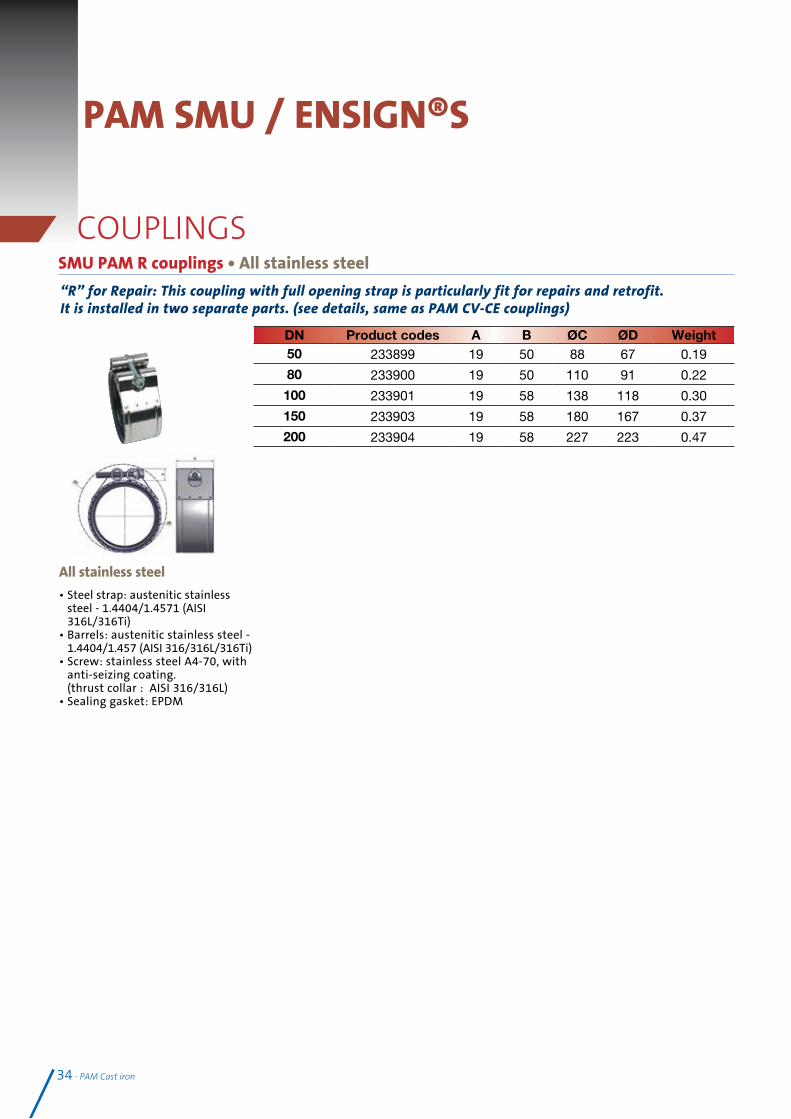
SMU PAM R couplings • All stainless steel
“R” for Repair: This coupling with full opening strap is particularly fit for repairs and retrofit. It is installed in two separate parts. (see details, same as PAM CV-CE couplings)
• Steel strap: austenitic stainless steel - 1.4404/1.4571 (AISI 316L/316Ti)
• Barrels: austenitic stainless steel - 1.4404/1.457 (AISI 316/316L/316Ti)
• Screw: stainless steel A4-70, with anti-seizing coating. (thrust collar : AISI 316/316L)
• Sealing gasket: EPDM
All stainless steel
DN Product codes A B ØC ØD Weight50 233899 19 50 88 67 0.19
80 233900 19 50 110 91 0.22
100 233901 19 58 138 118 0.30
150 233903 19 58 180 167 0.37
200 233904 19 58 227 223 0.47
34 - PAM Cast iron
PAM SMU / ENSIGN®S
COUPLINGS

PAM Cast iron - 35
PAM GRIP COLLARS
All dimensions are in mm and weights in kg. See p 44 for grip collars and couplings compatibility.
PAM grip collars
PAM grip collars for couplings
PAM Grip collars for expansion plugs
Designed by SAINT GOBAIN PAM, the PAM grip collar combines outstanding mechanical properties with very good pressure performance same as those of the PAM designed cou-plings, far over the Standard requirements.
The thorough selection of the steels also ensures a very good corrosion resistance.
This grip collar tightens “null gap”, there is no use checking the torque.
Technical specificationsFrames : Galvanised steelGrips : Stainless steel + treatmentTightening plates : Galvanised steelScrews : Coated steel - class 8-8
Totally versatile, the PAM grip collar is compatible with all the PAM designed couplings or of equivalent shape.
Pressure resistanceDN 50-125: 10 barDN 150 -200: 5 barDN 250-300: 3 bar
DN Product code D ≈ P ≈ L ≈ M ≈ Wrench
dim.Weight
50 221261 88 22 72 76 6 0.4575 SMA 221266 110 22 74 79 6 0.5475/80 221268 105 25 73 78 6 0.53100 220750 145 33 88 93 6 0.90150 221270 196 32 96 102 6 1.23200 221271 252 32 115 118 8 1.72250 227039 318 38 131 140 8 2.25300 227040 371 38 131 140 8 2.50
Rainwater pipe systems or drainage pipe systems can undergo accidental overpressure due to overloading or to the saturation of the sewer main. In specific sections - changes of direction and gradient, branches and plugs - the leak tightness and the pipe work stability call for joints able to address end thrust efforts.Depending on the diameter and the pressure level targeted combinations of couplings and grip collars or self-anchored high pressure couplings can equally be used. Where couplings are used with grip collars, the pressure performance of the assembly is defined by the weaker of the two products. Refer to the products specifications page 46.
DN Product code D ≈ P ≈ L ≈ M ≈ Wrench dim. Weight50 222092 88 22 43 47 6 0.33
75 SMA 222093 110 22 43 47 6 0.4275/80 222127 105 25 41 47 6 0.40100 221563 145 33 45 50 6 0.61150 222131 196 32 51 56 6 0.89200 222133 252 32 60 64 8 1.20
Pressure resistanceDN 50-125: 10 barDN 150 -200: 5 bar
For DN 250 and DN 300 use plain plugs + couplings with PAM grip collars for cou-plings.
36 - PAM Cast iron
PAM SMU / ENSIGN®S
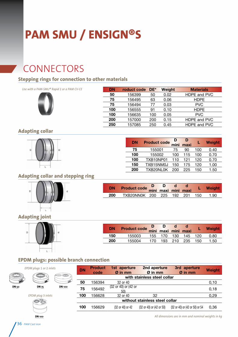
CONNECTORSStepping rings for connection to other materials
Adapting collar
Adapting collar and stepping ring
Adapting joint
EPDM plugs: possible branch connection
All dimensions are in mm and nominal weights in kg
DN roduct code DE* Weight Materials50 156399 50 0.02 HDPE and PVC75 156495 63 0.06 HDPE75 156494 77 0.03 PVC100 156555 91 0.10 HDPE100 156635 100 0.05 PVC200 157000 200 0.15 HDPE and PVC250 157085 250 0.45 HDPE and PVC
DN Product codeD
miniD
maxi L Weight
75 155001 75 90 100 0.40100 155002 100 115 100 0.70100 TXB10NP01 110 121 120 0.70150 TXB15NM0J 150 175 120 1.00200 TXB20NL0K 200 225 150 1.50
Use with a PAM-SMU® Rapid 2 or a PAM CV-CE
DN 100
DN 50 DN 75 DN 100
EPDM plugs 1 or 2 inlets
EPDM plug 3 inlets
DN Product codeD
miniD
maxid
minid
maxi L Weight
200 TXB20NN0K 200 225 192 201 150 1.90
DN Product codeD
miniD
maxid
minid
maxi L Weight
150 155003 155 170 130 145 120 0.80200 155004 170 193 210 235 150 1.50
DN Product
code1st aperture
Ø in mm2nd aperture
Ø in mm3rd aperture
Ø in mmWeight
with stainless steel collar50 156394 32 or 40 0,10
75 156492(32 or 40) or (42 or
50)0,18
100 156628 32 or 40 32 0,29without stainless steel collar
100 156629 (32 or 40) or 42 (32 or 40) or (42 or 50) (32 or 40) or (42 or 50) or 54 0,36

PAM Cast iron - 37
CONNECTORSPAM Konfix – For transitional connections
PAM Konfix-Multi – For transitional connections
PAM Multiquick – For transitional connections
The Multiquick connector DN 100x70 allows connections between other waste materials, with outside diameter ranking from 72 to 110 mm, to our cast iron range DN 100 with a maximum
outside diameter of 115 mm. Several pre-cut options.EPDM and hose clamp made of chrome steel n° 1.4016
To connect up to three pipes, 32-56 mm, made of other waste materials to a cast iron pipe system DN 100.EPDM and hose clamp made of chrome
steel n° 1.4016
Transitional connectors DN 50- 125 are devoted to connecting cast iron ranges S and Plus to other materials, be they steel or plastic. The connections with these flexible connectors are easy and safe: one pre-cut lid and a lip seal
inside (see figure).EPDM and hose clamp made of chrome steel n° 1.4016
DN Product code D1 DØ Da Connecting
pipe mmL1 L
Insert depth mm
Weight
50 155759 57 72 40-56 20 58 35 0,11100 155833 108 126 102-110 27.5 89.5 57 0,30125 155883 132 151 125 35.5 108.5 65 0,65
DN Product code D1 DØ Da Connecting
pipe mmL1 L
Insert depth mm
Weight
100 176811 108 134 32-56 35.5 90.5 40 0.30
DN Product ØD1 ØD2 ØD3 ØD4 Ød1 Ød2 Ød3 Ød4 H Weight100 x 70 176812 117 111 101 81 108 104 94 74 107 0,15

38 - PAM Cast iron

PAM Cast iron - 39
Specifier’s Manual
Sect
ion
3
SAINT-GOBAIN CAST IRON PIPE SYSTEMS1ST CHOICE FOR PROJECT MANAGERS AND PROFESSIONAL INSTALLERS
l Project support - assistance from our Technical Departments and commitment of our sales teams, to advise and help you to make the right choice.
l Traditional and precise mechanical assembly – with simple tools, without gluing or welding, to overcome on site difficulties.
l Simple to install, cast iron systems do not require specially trained installers to complete the installations.
l Dependable installation– SMU-Ensign ranges minimise the risk of error and help reach the expected performances immediately .

Modifications to an existing installation.Typical example spigot system
1. Measure length of branch, adding a further 15mm in total to allow for
coupling’s central register top and bottom.
2. Make sure existing pipework is adequately supported from above.
3. Mark pipe position for cutting.
4. Cut pipe using powered disc cutter or wheel cutter and remove sharp edges.
5. Coat cut ends with appropriate touch-up (epoxy coating).
6. Push the rubber gaskets onto the spigot cut ends top and bottom, ensuring
the central registers are abutted against each spigot edge.
7. Position fitting in the stack within each rubber gasket abutting against the
central registers.
8. Loosely assemble the coupling around each gasket.
9. Check alignment of assembly before tightening the bolts, to recommended
level, depending on the couplings technical recommendations.
10. Test new stack for successful joints.
40 - PAM Cast iron
Design recommendations
Hacksaw Pipe cutter Band sawPowered disc
cutterS And Plus ranges
DN40DN50DN75DN100DN125DN150DN200DN250DN300
Reciprocating saw can be used, but is not fully adapted.
X = fitting + 15mm
x
Installation featuresPreparation Cast iron pipe systems for drainage mainly consist of spigot pipes - generally supplied in 3 m length - and fittings of various shapes (bends, branches, etc.). The cast iron pipes can be cut to length. Where pipes are cut on site, ends shall be cut clean and square with burrs removed and then re-coated with the adequate touch-up paints .
Cutting techniquesSMU pipes can be cut easily and quickly using either of the following methods. It should be ensured that cutting procedures comply with the safety guidelines from the cutting tool manufacturer’s operating manual.
WARNING Chain or compression type cutters should not be used.

PAM Cast iron - 41
Stainless steel couplingsSome models can be assembled in two parts and other can be assembled as a sleeve.
Assembly as a sleevePAM Rapid NG couplingsCouplings are supplied pre-assembled.
Push the supplied assembled coupling onto the pipe spi-got so that it abutts on the central register of theelastomer gasket.
Push the next pipe pigot into the other end of the coupling.
Tighten the screw to“nul gap” position, that is fully closed, with a ratchet spanner or an electric screwdriver.
The PAM Rapid NG from DN 50 to 200 is designed to be tighte-
ned to fully closedthere is no need for checking the torque.
Jointing methods
PAM Rapid 250-300 coupling - Special design: can be assembled two different ways, depending on if an open strap is required.
Standard assembly: 1 Open the stainless steel strap.
2 Slide the stainless steel strap loose, around the first pipe compo-nent.
3 Push the sealing gasket onto the component spigot so it abuts on the central register of the gasket.
4 Push the second component into the sealing gasket, so that it abuts on the central register.
5 Bring the steel strap over the sealing gasket.
6 Tighten the bolt with a ratchet spanner or a power tool applying the following tightening torque: DN 250 and DN 300=25 N.m.
1 2
3
4
5
6
Open strap assembly: An open strap is sometimes required to ease access: stack installation etc…
1 Push the rubber gaskets onto the spigot ends top and bottom, ensuring the central registers are abutted against each spigot edge.
2 Twist the stainless steel strap to ease the wrapping around the pipe components.
3 Clip the bolt and loosely assemble the coupling around the gasket.
4 Check alignment of assembly before tightening the bolt with a ratchet spanner or a power tool applying the following tightening torque: DN 250 and DN 300= 25 N.m.
3 bis1 2
3
4
Wherever couplings can be submitted to end thrust forces, they must be secured with grip collars. See p48 for installation details.

42 - PAM Cast iron
(1) First grade is according to EN 10027-2, grade in brackets to the closest AISI one considering equivalences between standards. (2) As per EN ISO 3506-1(3) Standard tightening to reach EN 877 requirements. For higher requirements on pressure resistance, “nul gap” tightening should be applied.(4) See EN 877 for more details(5) Where couplings are used with grip collars, or for SMU-S Autogrip couplings, deflection should be applied before tightening the bolts/screwsNote: 1 bar = 100 kPa = 0.1 MPa ≈ 1 daN/cm2≈10 m water column
Technical characteristics Couplings technical features
PAM Rapid NG W2All stainless steeel
PAM Rapid NG W5
Rapid S NG 250-300
All stainless steel Rapid NG 250-300
Strap/case material (1)
Stainless steel1.4510 /11
(430Ti / 439)
Stainless steel 1.4404 / 1.4571
(316L/316Ti)
Stainless steel1.4510 /11
(430Ti / 439)
Stainless steel 1.4404 / 1.4571
(316L/316Ti)
Screws Allen
Wrench dimension (in mm) DN 50-150: 6DN 200: 8 DN 250-DN 300:8
Number 1 1 1 1
Screws Material
Coated steel class 8.8
Coated stainless steel A4-70
1,4404/1,4571
Coated stainless steel A2-70
Coated stainless steel A4-70
Tightening torque (in N.m) Nul gap tightening. No use checking torque DN 250-300 : 25 N.m
Clamp and barrel Clamps Barrels
Material (1)Stainless steel
1,4301 or 1.4510 /11 (304 or 430Ti / 439)
Stainless steel 1.4404 / 1.4571
(316L/316Ti)
Stainless steel 1,4301 or 1.4510 /11
(304or 430Ti / 439)
Stainless steel 1.4404 / 1.4571
(316L/316Ti)
Number 2 2 2 2
Sleeve (gasket) EPDM EPDM or NBR EPDM EPDM
Performances In In compliance with EN 681-1 December 1996 -Type WC
Maximum deflection (4) DN 50-200: 3° DN 250-600: 1,45° (5)
Maximum misalignment (4)
Corresponding to a shearing load of 10 X DN in Newton, limited to 6mm, under an internal pressure of 1 bar
Hydrostatic test pressure
Beyond EN 877 requirements- DN 50 to 125: 10 barDN 150 to 200: 5 bar - DN 250-300: 3 bar
* Grip collars are unecessary for couplings on straight runs between two fix points ** Same for the self-anchored couplings like the PAM HP GRIP which can be replaced under the same circumstances by couplings
able to withstand the required hydrostatic pressure.
Couplings + grip collars: performance level
Couplings Grip collars DNAddress end thrust effort for a pressure of (in bars)
3b 5b 10b
Expansion plug Expansion plug 50 - 125 10b
150 - 200 5b
250 - 300 3b
Expansion plug PAM Grip Collars for Expansion plugs 50 - 125 10b
150 - 200 5b

PAM Cast iron - 43
Rubber transitional connectors PAM KONFIX and PAM KONFIX-Multi are used to connect waste pipes made of other material (steel or plastics) to a PAM cast iron pipe system.
Branch connections to waste pipes in small diametersThe easiest way to connect cast iron systems to other drainage materials is to use rubber connectors or plugs. Flexible couplings and stepping rings are also available to ease connections where variances in diameters have to be compensated.
Design recommendationsConnection to other materials
1.Insert the PAM KONFIX rubber connector loosely onto the pipe until the stop point is reached. Then secure to the pipe by tigh-tening the hose clamp screw.
2. Cut the precut rubber to size with a knife and remove the lid. WARNING: Do not cut too deep as may damage the lip seal inside!
3. Mark the insert depth on the connecting pipe. Apply a lubricant and push in. The assembly is completed
4.The connecting steel pipe illustrated here is only an example. The PAM KONFIX rubber connectors can be used to connect all waste pipe mate-rials to the PAM cast iron systems.
Konfix Konfix-Multi
EPDM plugsThe plugs can be pierced to the appropriate groove from 32mm up to 54mm waste connections and tear out centre disc where required.
DN 50 DN 75 DN 100
EPDM plugs 1 or 2 inlets
DN 100
EPDM plug 3 inlets
PAM MULTIQUICK, transitional connector. To connect PAM cast iron pipes with an outside diameter of 109-112 mm (tolerance range for PAM cast iron pipes DN 100) to other rigid materials with an outside diameter range 110-72 mm.
To connect PAM cast iron pipes with an outside diameter of 109-112 mm to waste pipes with an outside diameter up to 115 mm maximum. The connection is made with two hose clamps both suitable to address larger diameter tolerances.
1. Push the open end of the PAM MULTIQUICK connector over the pipe end and place the hose clamp to its tightening position.
2. Then use a knife to cut open the pre cut lid to the corresponding outside diameter of the connecting waste pipe. Then push the second hose clamp loose over the connecting rubber end.
3. Push the connecting pipe into the PAM MULTIQUICK connector and tighten the hose clamp in the right position. Ensure that the sealing zones (face ends of pipes or fittings) are clean: remove paint flakes and cement residues. The hose clamps should only be tightened manually with a screwdriver in order to avoid any damage to the PAM MULTIQUICK rubber connector.

Admissible tolerance couplings (mm)Material to
connectDN/OD (mm)
Circumference ( mm)
PAM cast ironDN (mm)
DN/OD (mm)
DN/OD Tolerance (mm)
Solution Junctions product codes FigureSpecial joints PAM couplingsDN/OD Circumference DN/OD Circumference
49-52 153-163
55-60 172-188
P.V.C HDPE
50 157
50 58+ 2 -1
PAM CV NG + BC 210398 -156399 1
SMU PAM R + BC 233899 - 156399
HDPE 56 176PAM CV NG 210398
4SMU PAM R 233899
62-65 194-20481-86 254-270
P.V.C HDPE
63 197
75 83+2 -1
PAM CV NG + BC 210413 -1564951
SMU PAM R + BC 233900 -156495
75-79 235-248 P.V.C HDPE 75 235 PAM CV NG +BC 210413 -156494 1
75-90 235-282P.V.C
80 251 SMU ”MA” 155001 3
89-92 279-288
107-112 335-351
P.V.C HDPE
90 282
100 110+2 -1
PAM CV NG + BC 210416 -156555
1SMU PAM R + BC 233901 - 156555
99-102 310-320 P.V.C. 100 314PAM CV NG +BC
210416 - 156635 1
P.V.C HDPE 110 345 PAM CV NG 210416 4
100 - 115 314-361 Steel 114 358 SMU ”MA” 155002 3
123-127 386-398 133-138 417-433 P.V.C HDPE 125 392125 135
+2 -2
PAM CV NG + BC 210417 + 156778 1
130-150 408-471 Steel 125 436 SMU ”MA” TXB12NLOG 3
130-145 408-455P.V.C 140 439
150 160+2 -2
SMU “RA” 155003 2155-170 486-534
158-164 496-514 P.V.C HDPE 160 502 PAM CV NG 210418 4
150-175 471-549 Steel 168 527 SMU ”MA” TXB15NMOJ 3
198-202 621-634 207-213 649-668 P.V.C HDPE 200 628200 210
+2,5 -2,5
PAM CV NG + SR 210420 + 157000 1
200-225 628-706 Steel 219 688 SMU ”MA” TXB20NLOK 3
248-252 778-791271-276 850-868
P.V.C HDPE 250 785250 274
+2,5 -2,5
PAM CV NG + SR 210422 + 157085 1
273 857 PAM CV NG 210422 4
310-335 973-1051 P.V.C HDPE 315 989300 326
+2,5 -2,5
SMU“MA” TXB30NN02 3
323-328 1014-1031 Steel 324 1017 PAM CV NG 210423 4
44 - PAM Cast iron
Design recommendationsConnections to other materialsPAM cast iron connections to other material may be frequently required in new construction projects or for renovation. Different solutions can be used with products from our catalogue (see figures below).
Depending on the outside diameters, solutions exist for compensation.
If you have a doubt as for the circumference of the material to connect, you can use a circumference tape
The range of tolerance of the different joints can help you find the required solution.
You will find in the table below, the solutions to connect PAM cast iron to the most frequently met material.
3. Adapting collar = AC
Max Pressure 1,5 bar Stainless steel 304
1. PAM CV NG + Stepping ring (SR)
4. A=B
2. Adapting joint= AJ
Max Pressure 0,6 bar Stainless steel 304
PAM Rapid NG couplings 0can also be used but are not recommended for type 1 installation for aesthetical reasons.

PAM Cast iron - 45
Specific DN 70 / 75 connection with PAM CV-CE coupling
3. Fit the rubber gasket of the PAM CV-CE to the pipe end mounted with the stepping ring till it abuts the central register, then fit the DN 75 pipe end into the rubber gasket so that it abuts the central register as well.
DN 70 DN 75
4. Apply the PAM CV-CE NG steel strap around the sealing gasket and tighten as described p41.
DN 70 DN 75
2. Fit the stepping ring onto the DN 70 pipe end, first.
DN 70 DN 75
Product code : 156494 2104131. Stepping ring
+ PAM CV-CE NG coupling
DN 70 DN 75
Admissible tolerance couplings (mm)Material to
connectDN/OD (mm)
Circumference ( mm)
PAM cast ironDN (mm)
DN/OD (mm)
DN/OD Tolerance (mm)
Solution Junctions product codes FigureSpecial joints PAM couplingsDN/OD Circumference DN/OD Circumference
49-52 153-163
55-60 172-188
P.V.C HDPE
50 157
50 58+ 2 -1
PAM CV NG + BC 210398 -156399 1
SMU PAM R + BC 233899 - 156399
HDPE 56 176PAM CV NG 210398
4SMU PAM R 233899
62-65 194-20481-86 254-270
P.V.C HDPE
63 197
75 83+2 -1
PAM CV NG + BC 210413 -1564951
SMU PAM R + BC 233900 -156495
75-79 235-248 P.V.C HDPE 75 235 PAM CV NG +BC 210413 -156494 1
75-90 235-282P.V.C
80 251 SMU ”MA” 155001 3
89-92 279-288
107-112 335-351
P.V.C HDPE
90 282
100 110+2 -1
PAM CV NG + BC 210416 -156555
1SMU PAM R + BC 233901 - 156555
99-102 310-320 P.V.C. 100 314PAM CV NG +BC
210416 - 156635 1
P.V.C HDPE 110 345 PAM CV NG 210416 4
100 - 115 314-361 Steel 114 358 SMU ”MA” 155002 3
123-127 386-398 133-138 417-433 P.V.C HDPE 125 392125 135
+2 -2
PAM CV NG + BC 210417 + 156778 1
130-150 408-471 Steel 125 436 SMU ”MA” TXB12NLOG 3
130-145 408-455P.V.C 140 439
150 160+2 -2
SMU “RA” 155003 2155-170 486-534
158-164 496-514 P.V.C HDPE 160 502 PAM CV NG 210418 4
150-175 471-549 Steel 168 527 SMU ”MA” TXB15NMOJ 3
198-202 621-634 207-213 649-668 P.V.C HDPE 200 628200 210
+2,5 -2,5
PAM CV NG + SR 210420 + 157000 1
200-225 628-706 Steel 219 688 SMU ”MA” TXB20NLOK 3
248-252 778-791271-276 850-868
P.V.C HDPE 250 785250 274
+2,5 -2,5
PAM CV NG + SR 210422 + 157085 1
273 857 PAM CV NG 210422 4
310-335 973-1051 P.V.C HDPE 315 989300 326
+2,5 -2,5
SMU“MA” TXB30NN02 3
323-328 1014-1031 Steel 324 1017 PAM CV NG 210423 4

46 - PAM Cast iron
Design recommendationsRequirements and permissible pressure loadStandard requirements according to EN 12056
Gravity waste water drainage systems and ventilation systems generally operate without pressure. This does not exclude however, the possibility of pressure arising in the systems under specific operating conditions.
EN 12056-1, Section 5.4.2 Water and Gas Tightness, states that drainage installations must be sufficiently water and gas tight to withstand pressures arising in operation.
Furthermore, EN 12056-5, Section 6.3 states relating to securing pipe systems: Non anchored pipes must be secured and/or supported in such a manner that they cannot be disconnected during use. The arising reaction forces must be addressed.
Definitions
Fluid pressure is the force the fluid exerts by surface unit, perpendicularly to this surface.
Pressure change applied to the surface of an enclosed fluid is transmitted evenly and undiminished in all directions. Robust cast iron components can address any pressure hazard, so the couplings will be submitted to the strain.
Couplings designed by SAINT-GOBAIN PAM are tested in hydrostatic pressure; grip collars and autogrip collars only are tested under end thrust forces.
PAM grip collars installation
Pressure definitionsHydrostatic pressure: outward pressure exerted by a non-moving (static) fluid everywhere perpendicular to the pipe walls or any other pipework element, like joints.
When it is stated that a coupling withstands a 5 bar hydrostatic pressure it comes to considering the coupling water tightness under this pressure only, whilst considering that the two spigots are affixed so that dislocation forces are addressed.
End thrust effect: resultant forces from the pressure exerted by a static fluid on specific pipework elements (or direction changes) i.e:- Straight run (pipes): the stresses cancel
- Specific (for i.e fitting): the resultant force tends to disconnection
FAQ
Position the two half parts of the PAM grip collar uniformly so it encircles the pipe in parallel .
The grip collars must be positioned so that the apertures fit over the fixing bolts of the coupling and the teeth are directly located onto the pipe.
Insert the four screws to fix the two parts together loosely.
Tighten the screws crosswise alterna-tively so that the two plates are put
in parallel with the same spacing.
The assembly is completed when the external edges of the plates are in contact on both sides.

DN 50 DN 75 DN 100 DN 125 DN 150 DN 200 DN 250 DN 300 DN 400 DN 500 DN 600Expansion plug
2 5 9 13 19 32 55 79 136 210 301
2 45° bends
3 7 12 19 26 46 78 111 192 297 426
Stack bottom
2 5 9 13 19 32 55 79 136 210 301
PAM Cast iron - 47
Requirements and permissible pressure loads for couplingsConditions when drainage pipeworks may be exposed to an internal pressure higher than 0.5 bar:1. Pipes laid under the groundwater table2. Rainwater pipes or wastewater pipes running through several storeys without outlets3. Pipework operating under pressure for wastewater pumped installations
Straight runs of the pipeworkStraight runs between two fixed points do not experience exceptional forces, grip collars are then not necessary.In case of accidental overloading, the couplings will only have to address hydrostatic pressure. They generally withstand:5 bar for couplings like PAM Rapid S or SMU PAM R from DN 50 to 2003 bar for the same couplings for DN 250 and 300
Changes of direction and specific elementsEnd thrust forces can exert in changes of direction, gradient and specific components like branches and plugs for example. In these areas, the forces have to be addressed to avoid any risk of disconnection or slippage of the pipe system:• isolating the section subjected to thrust forces between two fixed points, like stack support pipes i.e and• adapting the joints (selection of couplings + installation of grip collars) between these fixed points.To address the thrust forces, other solutions can be resorted to, like anchoring in concrete, or using mechanically-welded devices...
Remark: under end thrust forces, where a coupling is secured with a grip collar, the maximum performance of both is limited by the weakest performance of the two products.
End thrust force under a 1m water column (kg.F)
Specific applications: Rainwater pipesEN 12056-3, Section 7.6.4., stipulates: Internal rainwater pipes shall be able to withstand the head of water likely to occur in theevent of a blockage.The same precautions as on a pipework liable to undergo accidental overloading should be taken: securing of bottom bends and joints with the adequate grip collars.
Stack support pipes
Grip collars on couplings
Grip collars on couplings Couplings alone
Ensure that the installation instructions for couplings and grip collars are observed.See coupling performances on page 44
PAM Couplings and grips collar have been designed to reach the same pressure performance and beyond the standard requirements.

48 - PAM Cast iron
A drainage pipe is normally at neutral air pressure compared to the surrounding atmosphere. When a column of waste water flows through a pipe, it compresses air in the pipe, creating a positive pressure that must be released or will push back on the waste stream and downstream traps’ water seals. As the column of water passes, air must flow in behind the waste stream or negative pressure (suction) results. The extent of these pressure fluctuations is determined by the fluid volume of the waste discharge.
The purpose of ventilation stack is to control pressure in the pipework in order to prevent foul air from the waste water system entering the building. You will find below some major configurations principles, but combinations and variations are often required. See standard EN 12056-2
Black water and grey water can be drained either in separate or in a single discharge stack. According to the selected option, the rules for duct sizing are different.
Design recommendationsVentilation
Primary ventilated system configurations:
Control of pressure is achieved by air flow in the discharge stacks. The soil stacks extend in main roof vents to above and out of the roof. Alternatively, air admittance valves may be used. They are pressure-activated, one-way mechanical vents, used in a plumbing system to eliminate the need for conventional pipe venting and roof penetrations.
Secondary ventilated system configurations
In buildings of three or more storeys - if the air pressure within the stack becomes suddenly higher than ambient, this positive transient could cause waste water to be pushed into the fixture, breaking the trap seal.
Vent stacks are put in parallel to waste stacks to allow proper venting and prevent such disorders. Air admittance valves may also be used, in this configuration.
Under many building codes, a vent stack, a pipe leading to the main roof vent, is required to the draining fixtures (sink, toilet, shower stall, etc.).
To allow only one vent stack, and thus one roof penetration as permitted by local building code, sub-vents may be tied together and exit a common vent stack.
A single stack is still possible but design precautions have to be taken to prevent self-siphonage.

PAM Cast iron - 49
Roof penetration deviceTo secure roof watertightness, which is of crucial importance, the number of roof penetrations should be limited. SAINT-GOBAIN PAM has designed for its pipe systems, a roof penetration device that is watertight and quick to install.
The system was developed to ease installation of perfectly watertight roof penetration for cast iron primary ventilation pipes or vent pipes. The flanged
fittings clamp both the vapour barrier and the waterproofing layer.
The first flange fitting, installed above the roof clamps the vapour barrier under the roof insulating layer, the second, above the insulating layer clamps the waterproofing layer, be it polymer or bituminous.
Roof insulating layer
Roof (corrugated steel roofing,
concrete roofing…)
Vapour barrier
Waterproofing layer
The roof penetration device is a set of two ductile iron flanged fittings – one of the flanges is fixed, the second is movable - equipped with rubber gaskets.
Rubber gaskets are available in EPDM or NBR quality where hydrocarbons can be feared.
See product codes p 31

Typical manifold installation
The multi-waste manifold simplifies waste plumbing by grouping all associated pipework from various sources such as sinks, basins, bidets, urinals and showers to one internal point above the finished floor level.
The manifold will permit the connection of three 32/38mm copper/plastic waste inlets to any new or existing 100mm diameter PAM SMU / Ensign pipe stack and three 50mm copper/plastic waste inlets to 150mm diameter pipe stack.
The manifold main body is connected to the stack using standard couplings. On the 100mm manifold to achieve a 32mm waste connection, remove the inner rubber ring, 38mm utilising the outer ring (for waste pipe maximum lengths see EN 12056-2). Pipework connecting discharge appliances to the manifold, should be designed not to cause self siphonage.
Fixing instructions 1. Remove grommets, pierce the appropriate groove for 32mm or 38mm waste
(100mm manifold only) connections and tear out centre disc where required.
2. Apply an appropriate silicone grease (not provided) to the outside of the grommet and re-fit into manifold ensuring that the retaining groove of the grommet is located correctly in the casing.
3. Lubricate pipe ends and insert into grommet with a rotational movement. Pipe ends may be chamfered for ease of insertion.
4. Any grommet not fitted with a waste pipe must also follow instruction 2 above.
Beware the manifold is not made to vent the stack.
Design recommendationsMulti waste manifold
50 - PAM Cast iron

PAM Cast iron - 51
The CEBTP branch is a patented device made to allow wastewater drainage without vent pipes.
Given that the maximum number of connected sanitary appliances is respected, the single stack branch CEBTP properly drains waste water in a single stack, without vent pipes, whilst limiting the risks of self siphonage. This device complies with the Regulation in force and with Standard EN 12056.
Consult local requirements for compliance.
Field of use: - Multi connection of sanitary appliances for adjacent flats, or sanitary blocks - Compactness when the space is limited - No secondary vent pipes being required.
Drivers: It simplifies plumbing by grouping the pipeworks from 3 or 4 times more sources than a conventional installation. Maximum connections for each floor level: 2 toilets, 2 bathtubs and all the usual sanitary facilities for two flats (sinks, basins, showers…) The single stack branch is particularly suitable for narrow service shafts, for hotel rooms, student flats or any other building with adjacent sanitary blocks.
Operation features -Prevents excessive pressure variations in the stack system.
-Limits negative pressure by optimal venting and prevent self siphonage.
The single stack branch DN 100 main body is connected to the stack using standard couplings and a traditional jointing method. Their water tightness is ensured by the rubber gaskets which equip the SMU® S, SME and SMU® Plus product lines, proposed by SAINT-GOBAIN PAM.
The plumbing works overall shall be executed in compliance with standard EN 12056: the appliances are to be installed with traps in compliance with the specifications of the same standard.
Products: The single stack Branch now exists in long tail to allow connection to the main stack under the slab and thus ease installation either in new or renovation works.
Three different products, 2 or 3 inlets: - Corner branch two inlets 88° - Double branch two inlets 88° - A consecutive branch, three inlets 88°
Rubber plugs with several pre-cut lids will permit from one to three different connections.
Single stack branch
Owing to the special design of the branch, after a flush, the column of water is directed so that air can pass over the flow and naturally vent the stack.
Inside the branch, at the bottom of the body, a rubber deflector sprays the column of water to prevent draught or self siphonage.

Stack support pipe installed vertically
Stack support pipe installed horizontally
Stack support pipe for open hoppers.A pipework is submitted to different forces liable to affect its stability. Stack supports are cast iron components designed to address these efforts when a stack is installed through open hoppers.
On straight runs, stack support pipes should be installed to address the pipes weight. At the bottom of the stack, the first stack support pipe addresses both pipes weight and end thrust effort. For the last case, it is recommended that the support and fixings should be adapted accordingly.
We recommend to position the first stack support pipe at the base of the first floor, and then every subsequent fifth floor, in case of a standard average 2.5 m between floors, or more generally every 15 m.
In case of closed hopper, no stack support pipe is required.
Stack support pipe and acoustic insulationThe support bracket of the stack support is covered with rubber gasket to limit the transmission of structure-borne noise emitted by the drainage network at slab level.
During lab tests carried out in 2002*, a stack assembly including a stack support pipe on console support and a rubber lined bracket, both affixed to a wall with a surface density of 220 kg/m2 showed results slightly better than the same installation made with two fixings with rubber lined brackets. In this particular installation, the use of stack support pipes does not affect acoustic performance.
*Tests carried out according to standard EN 14366.
Either on cantilever arms or stack support consoles for DN 100.
Wall bracketing system in mild steel, for use with stack support pipes and brackets, is available.
52 - PAM Cast iron
Design recommendations
Rubber gasket
Pipeworks stability

At the bottom of the stack At changes of direction (stack offsets).
Access to the pipework must be ensured so that tests, inspections and maintenance can be performed. Access may be obtained using a short access pipe.
On horizontal runs, the short access pipe will be installed in a slightly sloped position with respect to the pipe crown.
Access to the pipework
Water flow and air circulation, according to the standard 12056-2 & 12056-3.
The internal diameter of pipes cannot be reduced in the direction of the water flow, except in the case of pipeworks operating at full bore, under negative pressure such as in the siphonic roof drainage system EPAMS.
The addition of branch connections, or changes of fall liable to increase the water flow rate, may require an increase of internal pipe diameter. This increase can be made upstream of the new branch connection, using a tapered pipe reducer (see page 31).
Rainwater horizontal pipelines
In horizontal and near horizontal pipelines, increases in size shall be installed such that the soffit is continuous in order to prevent air from being trapped.
On downpipes
On horizontal collectors
PAM Cast iron - 53
Water flowRainwater
Water flowWaste water

40 50 75 100 125 150 200 250 300 400 500 600Empty pipe 3 4 6 8 11 14 22 32 42 60 82 107Full pipe 4 6 11 16 24 31 54 82 113 185 278 390
Pipe support except for the EPAMS systemFor cast iron, the bracketing system is designed to only carry the weight of the pipe and its content, which makes the specifiers’ design work easier.
Note: The technical specifications for threaded rods and metal brackets shall be established on this basis.
It is also recommended to use one bracket per length or fitting (when the shape allows it, i.e branches…)
Support for horizontal pipeworkThe general recommendation for horizontal pipework is two load bearing brackets per pipe. For an indication, they should be installed at 0.75 m from each spigot so that, ideally, the distance between two brackets should be 1.5m. Installation shall respect a slight fall, around 1 or 2%, and 0.5% at a minimum, (0.5 cm per metre).
Support for vertical pipeworkFor vertical waste or rainwater stacks, the brackets aim at preventing the pipework to fall over. It is recommended that one bracket should be fitted for each floor level.
Ideally the bracket should be installed on the first third from the upper spigot, and even closer to a socket joint.
Pipe weight in kg per metre.
Bracketing recommendations for cast iron pipe system elements
Bottom of stacks
Design recommendationsBracketing: technical
Number of brackets
Vertical runPipes 1 (2)*
Fittings** 1
Horizontal runPipe length≥2m 2
Pipe length<2m 1
Fittings** 1
54 - PAM Cast iron
1,5 m mini
= =
Horizontal collectors
Consult local requirements for compliance.
* for SMU pipes L ≥ 2,7 m installed outdoor. ** when the shape of the fitting permits
Bracketing installations, openings and sealings are prohibited in prestressed girders.
As explained on p101, at the bottom of the stacks, the forces from the pipes weight and possible end thrust efforts will be preferably addressed through stack support pipes.
ENSIGN

Pipe support bracketThe unique, all-purpose, lightweight, ductile iron bracket incorporates an elongated slot at the fixing point. This allows both vertical and lateral adjustment without dismantling the pipe system.
ENSIGN®S pipe systems and ductile iron brackets
PAM Cast iron - 55
EF048
1 Meter
Max.
EF049
Length over 1 Meter Max.
M10 or M12
Typical support arrangement for vertical pipework
Typical support arrangement for horizontal pipework
EF049 EF048
S.V.P V.P

PAM Acoustic dampener
Acoustic bracket installation
The evacuation of waste, soil and rainwater generates structure-borne and airborne sound between rooms and usually occurs as the result of a mixed flow, when the pipe is filled with water and air. In such circumstances a pipe will radiate noise outwards and transfer it to any lightweight ceilings, cupboards and similar areas wherever it makes contact.
Horizontal pipework: fixing brackets on side as per diagram is not recommended. This will lead to product failure
All brackets within the SAINT-GOBAIN PAM range meet the requirements of the most demanding standards. For exceptionally high levels of acoustic performance, the standard ductile iron or steel brackets fitted with a new acoustic dampener should be used. The different assemblies have been tested to EN14366: Laboratory measurements of noise from waste water installations.
The PAM acoustic dampener has been developed to meet the increasing demand for buildings which require a high level of acoustic performance over regulations requirements.
PAM pipe installation fitted with acoustic dampener* Structure-borne noise: 2l/s = 5 dB - 4l/s = 11 dB
* IPB results, November 2006 installation according to EN 14366
Vertical For vertical pipe stack: one acoustic bracket minimum per 3 metres
HorizontalHorizontal suspended pipework: two acoustic brackets minimum per 3 metres.
Design recommendationsSpecific Bracketing for acoustic insulation
Material: 1. Dampener –elastomer EPDM2. M8-M10 nut – galvanised bichroma-
ted steel3. Retainer cup – AISI 304 stainless steel4. Small dish – AISI 304
stainless steel5. M8-M10 tapped base -
galvanised bichromated steel
12
3
45
56 - PAM Cast iron

PAM Cast iron - 57
Condensation on drainage pipeworkCondensation may appear whenever the temperature of the drainage pipes walls is lower than the dew point. This happens when the temperature of the fluid transported is much lower than that of the surrounding atmosphere and when the hygrometry level is high.
Possible local regulation or preventive solutions fall within the competence of the engineering and design department, after taking the building project specificities into account. According to the anticipated results and the requirements as regards fire protection of the building, solutions such as mineral wool, anti-condensation painting or finally, insulating strip can be considered.
Aggressive atmospheresPipes and fittings installed within an aggressive chlorine environment (swimming-pools) should be over-painted with a special air dry epoxy coating. Please refer to paint manufacturers to select the appropriate product to resist this specific stress.
In such atmosphere all stainless steel couplings are compulsory.
Aggressive soil conditions According to Annex C of EN 877, for pipes buried in contact with soils with a lower pH than 6, it is recommended they should be additionally protected with polyethylene sleeve or any other type of external coating as appropriate.
Cast iron protection: additional coating or overpainting
Do cast iron pipes need to be overpainted before installation?
The acrylic paint on the pipes is a primer which can be over painted with most top coats. Finish paint is necessary where the pipeworks are visible, indoor or outdoor. What types of paint can be used? Any alkyd resin, or glycerophtalic paint dedicated to metal care and suitable for the requirements of the local environment.
The system should be gently rubbed down with suitable abrasive paper, in order to provide a good adhesion key for the finish coating. Where the finish paint should be used on zinc coated pipes to rejuvenate them, rub them down gently to remove possible zinc salts.
Where incipient rust has already appeared on cast iron products, corrosion inhibitors can be used before painting. Some existing metal finishes including anti-corrosive pigment can be applied directly to rust.
FAQ

Design recommendations
58 - PAM Cast iron
The SMU - Ensign Plus pipes can be used in below ground applications. Buried pipes are subject to mechanical strain due to the weight of grounds and possibly wheel loading when they are laid under a circulating area.
The mechanical performance of a buried pipework is to be considered as a pipe/ soil system: the interaction of the pipes with the surrounding soils depends on their stiffness or flexibility, and the selected type of laying condition.
The choice of bedding and backfilling depends on the depth at which the pipes have to be laid, the size and the strength of the pipes. The standard EN 1610 “Construction and testing of drains and sewers” applies to drains normally buried in the ground and normally operating under gravity.
You will find below the hypothesis for rigid pipes retained for the calculation of allowable depth of cover.
Installation parameters are laid down according to: - Soil type (see groups below)- Quality of compaction of the embedment - Behaviour of the pipe (rigid for cast iron)- Presence of wheel loads or not- Particular conditions (groundwater table…)
Buried pipe systems
DN 100 to DN 300
Modulus of Young : 110000 N/mm2
Poisson’s ratio : 0.25Max. stress : 350 N/mm2
Strain coefficient : 1.5Buckling Coefficient : 2.5Geometrical defect : 1.2 + DN/2000 mm
Backfilling recommendations from DN 100 to DN 300, with or without traffic loads (according to EN 1610).Two main solutions have been retained out of the EN 1610 recommendations, taking into account both ease of installation and knowledge from experience of rigid pipe systems. For compaction, the more adverse hypothesis was retained.
These solutions maximise the advantage from cast iron’s mechanical properties: depth of cover they can withstand, possible backfilling with native soil removed, thereby limiting the damage to the environment…
100min
Depth of cover
Grade line
Native soil
Particles < 22mm
Native soil with no particle > 40mm
Native soil free from
detrimental materials*
300mini
Case N°1
100min
Depth of cover
Native soil
Particles < 22mm
Native soil with no
particle > 40mm
DE/2
Grade line
300 mini
Native soil free from
detrimental materials*
Case N°2
Dimensions are in mm* Detrimental materials = stones; tree roots; rubbish; organic material; clay lumps (>75 mm); snow and ice.
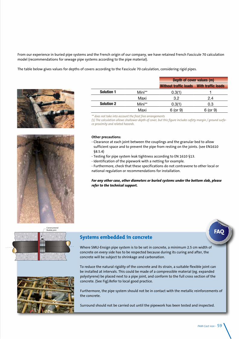
PAM Cast iron - 59
Other precautions:- Clearance at each joint between the couplings and the granular bed to allow
sufficient space and to prevent the pipe from resting on the joints. (see EN1610 §8.5.4)
- Testing for pipe system leak tightness according to EN 1610 §13.- Identification of the pipework with a netting for example.- Furthermore, check that these specifications do not contravene to other local or national regulation or recommendations for installation.
For any other case, other diameters or buried systems under the bottom slab, please refer to the technical support.
From our experience in buried pipe systems and the French origin of our company, we have retained French Fascicule 70 calculation model (recommendations for sewage pipe systems according to the pipe material).
The table below gives values for depths of covers according to the Fascicule 70 calculation, considering rigid pipes.
** does not take into account the frost free arrangements(1) The calculation allows shallower depth of cover, but this figure includes safety margin / ground surfa-ce proximity and related hazards.
Systems embedded in concrete
Where SMU-Ensign pipe system is to be set in concrete, a minimum 2.5 cm width of concrete on every side has to be respected because during its curing and after, the concrete will be subject to shrinkage and carbonation.
To reduce the natural rigidity of the concrete and its strain, a suitable flexible joint can be installed at intervals. This could be made of a compressible material (eg. expanded polystyrene) be placed next to a pipe joint, and conform to the full cross section of the concrete. (See Fig).Refer to local good practice.
Furthermore, the pipe system should not be in contact with the metallic reinforcements of the concrete. Surround should not be carried out until the pipework has been tested and inspected.
FAQ
�
Depth of cover values (m)Without traffic loads With traffic loads
Solution 1 Mini** 0.3(1) 1
Maxi 3.2 2.4Solution 2 Mini** 0.3(1) 0.3
Maxi 6 (or 9) 6 (or 9)

Standards specificationsEN 877:1999 + Amendment / A1: 2006 + Corrigendum / AC: 2008
Cast iron pipes and fittings, their joints and accessories for the evacuation of water from buildings – Requirements, test methods and quality assurance.
Scope:This European Product Standard applies to cast iron pipework elements used for the construction, normally as gravity pipe systems, of discharge systems for buildings and of drains. The range of nominal diameters extends from DN40 to DN600 inclusive. This standard specifies the requirements for the materials, dimensions and tol-erances, mechanical properties, appearance and standard coatings for cast iron pipes, fittings and accessories. It also indicates performance specifications for all components, including joints. It covers, above ground soil, waste, rainwater and buried systems and performance requirements in these applications.
The concerned ranges:PAM-SMU S and Plus, PAM-ENSIGN S and Plus: DN 40 to 600Rainwater range: DN 75 to 150
Definitions:Discharge system for buildings: system of pipes, fittings, accessories and joints used to collect and drain waste water and rainwater from a building; it comprises discharge pipes, ventilation stacks and rainwater pipes, installed within the limits of a building or attached to the building.
Drain: system of pipes, fittings, accessories and joints installed outside the limits of a building in order to connect the discharge system of this building to a soil and drain or a septic tank.
Sewer: system of pipes designed to collect waste water and rainwater from buildings and surface water and to convey them to the point of disposal or treatment.
Requirements:Adhesion see 4.6Hot water resistance: 24 H at 95°C and thermal cycles (1500 cycles of 1min between 15 and 93°C)Salt spray resistance: 350 h Chemical resistance: 2 >pH > 12 at 23°CTo test the chemical resistance of cast iron products standard EN 877 defines that product samples shall be immersed - for 30 days and held at (23 + 3)°C, the pH being constantly monitored - in the following test liquids:- a solution of sulfuric acid at pH 2, for the first sample;- a solution of sodium hydroxide at pH 12, for the second sample.- a solution of waste water at pH 7 for the third sample.
Dimensions - External diameter (DE) see 4.2.2Coatings for pipes and fittings: general see 4.6Specific requirements for coatings for buried systems and rainwater systems installed outside buildings are given in 4.8.3 and 4.9.2 respectively.
Water tightness Joints water tightness – Performance requirements see 4.7.5Reaction to fire see EN 877:1999/A1:2006/AC -4.6.3 External coatings and 5.7.3.3Noise protection see EN 877:1999/A1 - 4.1.4
60 - PAM Cast iron

CE Marking (see Section 1 p 15)
To allow free circulation of industrial products within the European Union, while guaranteeing the safety of European consumers and users of the products, construction products must meet essential requirements covering public health, safety and consumer protection.Based on EN 877, CE marking became mandatory on cast iron wastewater products leaving the European factory, from 1st September 2009.
Do not hesitate to compare the reaction to fire classifications of the materials you specify.Remember that CE marking is not a Quality mark or label. Its scope is limited to health and operation safety. It is intend-ed mainly for the authorities in charge of market control.
Product standards and Quality marksStandard EN 877, which defines the requirements for cast iron wastewater pipe systems, is a self-declared standard. This means that the manufacturer is allowed to self declare that his product complies with this standard except for reaction to fire classification of the range which requires an initial type test by a notified test laboratory.
Quality Marks, proof of conformity with EN 877
Voluntary Quality marks aim at fitness for purpose. They add value to the product in terms of customer-supplier relationships.
Only compliance with EN 877 that is validated by a third party for all criteria, and periodically tested, can guarantee the performance of the systems you specify.Look for cast iron products fully complying with EN 877, bearing a quality mark, such as a Kitemark, NF or Watermark for example, being delivered by an accredited certification body.
BS EN 877:1999 Kitemark KM51733Ensign (S and Plus) is the only cast iron system to be tested and awarded Kitemark approval to the product standard in the UK.
NF EN 877:1999 NF
SMU S and Plus ranges, SME
EN 12056
Gravity drainage systems inside buildings
It covers waste water drainage systems which operate under gravity. It is applicable for drainage systems inside dwellings, commer-cial, institutional and industrial buildings and sets out principles to be followed for both layout and calculation. It makes limited pro-vision for drainage systems conveying trade effluent and also makes limited provision for fluids removed by pumps.
Differences in plumbing within Europe have led to a variety of systems being developed. Some of the major systems in use are described in this standard.
Part 1: General and performance requirements.Part 2: Sanitary pipework, layout and calculation.Part 3: Roof drainage, layout and calculation.Part 4: Wastewater lifting plants - Layout and calculation.Part 5: Installation and testing, instructions for operation, maintenance and use.
PAM Cast iron - 61

J Q v Q v Q v Q v Q v Q v Q v Q v cm/m l/s m/s l/s m/s l/s m/s l/s m/s l/s m/s l/s m/s l/s m/s l/s m/s 0.5 0.8 0.4 0.9 0.4 2.1 0.5 3.7 0.6 6.0 0.7 12.5 0.8 25.8 1.0 41.3 1.1 0.6 0.9 0.4 1.0 0.4 2.3 0.6 4.1 0.6 6.6 0.7 13.7 0.9 28.3 1.0 45.3 1.2 0.7 0.9 0.5 1.1 0.5 2.5 0.6 4.4 0.7 7.1 0.8 14.8 0.9 30.6 1.1 48.9 1.3 0.8 1.0 0.5 1.1 0.5 2.7 0.6 4.7 0.7 7.6 0.8 15.8 1.0 32.7 1.2 52.3 1.4 0.9 11 0.5 1.2 0.6 2.9 0.7 5.0 0.8 8.1 0.9 16.8 1.1 34.7 1.3 55.5 1.4 1.0 1.1 0.6 1.3 0.6 3.0 0.7 5.3 0.8 8.5 0.9 17.7 1.1 36.6 1.3 58.5 1.5 1.1 1.2 0.6 1.4 0.6 3.2 0.8 5.5 0.9 8.9 1.0 18.6 1.2 38.4 1.4 61.4 1.6 1.2 1.2 0.6 1.4 0.6 3.3 0.8 5.8 0.9 9.4 1.0 19.4 1.2 40.1 1.5 64.2 1.7 1.3 1.3 0.6 1.5 0.7 3.4 0.8 6.0 1.0 9.7 1.1 20.2 1.3 41.8 1.5 66.8 1.7 1.4 1.3 0.7 1.5 0.7 3.6 0.9 6.3 1.0 10.1 1.1 21.0 1.3 43.4 1.6 69.3 1.8 1.5 1.4 0.7 1.6 0.7 3.7 0.9 6.5 1.0 10.5 1.2 21.7 1.4 44.9 1.7 71.8 1.9 1.6 1.4 0.7 1.6 0.7 3.8 0.9 6.7 1.1 10.8 1.2 22.4 1.4 46.4 1.7 74.1 1.9 1.7 1.5 0.7 1.7 0.8 3.9 0.9 6.9 1.1 11.1 1.2 23.1 1.5 47.8 1.8 76.4 2.0 1.8 1.5 0.8 1.7 0.8 4.1 1.0 7.1 1.1 11.5 1.3 23.8 1.5 49.2 1.8 78.7 2.0 1.9 1.5 0.8 1.8 0.8 4.2 1.0 7.3 1.2 11.8 1.3 24.5 1.6 50.6 1.9 80.8 2.1 2.0 1.6 0.8 1.8 0.8 4.3 1.0 7.5 1.2 12.1 1.3 25.1 1.6 51.9 1.9 82.9 2.1 2.5 1.8 0.9 2.0 0.9 4.8 1.2 8.4 1.3 13.5 1.5 28.1 1.8 58.0 2.1 92.8 2.4 3.0 1.9 1.0 2.2 1.0 5.3 1.3 9.2 1.5 14.8 1.6 30.8 2.0 63.6 2.3 101.7 2.6
Filling level 50 % (h/d=0.5)
DN 70 DN 75 DN 100 DN 125 DN 150 DN 200 DN 250 DN 300 di = 71 di = 75 di = 103 di = 127 di = 152 di = 200 di = 263 di = 314
J Q v Q v Q v Q v Q v Q v Q v Q v cm/m l/s m/s l/s m/s l/s m/s l/s m/s l/s m/s l/s m/s l/s m/s l/s m/s 0.5 1.3 0.4 1.5 0.5 3.6 0.6 6.2 0.7 10.1 0.7 20.8 0.9 43.1 1.1 68.9 1.2 0.6 1.4 0.5 1.7 0.5 3.9 0.6 6.8 0.7 11.0 0.8 22.9 1.0 47.2 1.2 75.5 1.3 0.7 1.6 0.5 1.8 0.5 4.2 0.7 7.4 0.8 11.9 0.9 24.7 1.1 51.1 1.3 81.6 1.4 0.8 1.7 0.6 1.9 0.6 4.5 0.7 7.9 0.8 12.7 0.9 26.4 1.1 54.6 1.3 87.3 1.5 0.9 1.8 0.6 2.1 0.6 4.8 0.8 8.4 0.9 13.5 1.0 28.1 1.2 58.0 1.4 92.6 1.6 1.0 1.9 0.6 2.2 0.7 5.1 0.8 8.8 0.9 14.3 1.1 29.6 1.3 61.1 1.5 97.6 1.7 1.1 2.0 0.7 2.3 0.7 5.3 0.9 9.3 1.0 15.0 1.1 31.0 1.3 64.1 1.6 102.4 1.8 1.2 2.0 0.7 2.4 0.7 5.5 0.9 9.7 1.0 15.6 1.2 32.4 1.4 67.0 1.6 107.0 1.8 1.3 2.1 0.7 2.5 0.7 5.8 0.9 10.1 1.1 16.3 1.2 33.8 1.4 69.7 1.7 111.4 1.9 1.4 2.2 0.7 2.6 0.8 6.0 1.0 10.5 1.1 16.9 1.2 35.0 1.5 72.4 1.8 115.6 2.0 1.5 2.3 0.8 2.7 0.8 6.2 1.0 10.9 1.1 17.5 1.3 36.3 1.5 74.9 1.8 119.7 2.1 1.6 2.4 0.8 2.7 0.8 6.4 1.0 11.2 1.2 18.1 1.3 37.5 1.6 77.4 1.9 123.7 2.1 1.7 2.4 0.8 2.8 0.9 6.6 1.1 11.6 1.2 18.6 1.4 38.6 1.6 79.8 2.0 127.5 2.2 1.8 2.5 0.8 2.9 0.9 6.8 1.1 11.9 1.3 19.2 1.4 39.8 1.7 82.1 2.0 131.2 2.3 1.9 2.6 0.9 3.0 0.9 7.0 1.1 12.2 1.3 19.7 1.5 40.9 1.7 84.4 2.1 134.8 2.3 2.0 2.7 0.9 3.1 0.9 7.2 1.2 12.5 1.3 20.2 1.5 41.9 1.8 86.6 2.1 138.3 2.4 2.5 3.0 1.0 3.4 1.0 8.0 1.3 14.0 1.5 22.6 1.7 46.9 2.0 96.9 2.4 154.7 2.7 3.0 3.3 1.1 38 1.1 8.8 1.4 15.4 1.6 24.8 1.8 51.4 2.2 106.1 2.6 169.6 2.9
Filling level 70 % (h/d=0.7)
DN 70 DN 75 DN 100 DN 125 DN 150 DN 200 DN 250 DN 300 di = 71 di = 75 di = 103 di = 127 di = 152 di = 200 di = 263 di = 314
J Q v Q v Q v Q v Q v Q v Q v Q v cm/m l/s m/s l/s m/s l/s m/s l/s m/s l/s m/s l/s m/s l/s m/s l/s m/s 0.5 1.6 0.4 1.8 0.4 4.2 0.5 7.4 0.6 12.0 0.7 24.9 0.8 51.6 1.0 82.6 1.1 0.6 1.7 0.4 2.0 0.4 4.7 0.6 8.2 0.6 13.2 0.7 27.4 0.9 56.6 1.0 90.5 1.2 0.7 1.9 0.5 2.1 0.5 5.0 0.6 8.8 0.7 14.2 0.8 29.6 0.9 61.2 1.1 97.8 1.3 0.8 2.0 0.5 2.3 0.5 5.4 0.6 9.4 0.7 15.2 0.8 31.6 1.0 65.4 1.2 104.6 1.4 0.9 2.1 0.5 2.4 0.6 5.7 0.7 10.0 0.8 16.2 0.9 33.6 1.1 69.4 1.3 111.0 1.4 1.0 2.2 0.6 2.6 0.6 6.0 0.7 10.6 0.8 17.1 0.9 35.4 1.1 73.2 1.3 117.1 1.5 1.1 2.3 0.6 2.7 0.6 6.3 0.8 11.1 0.9 17.9 1.0 37.1 1.2 76.8 1.4 122.8 1.6 1.2 2.4 0.6 2.8 0.6 6.6 0.8 11.6 0.9 18.7 1.0 38.8 1.2 80.3 1.5 128.3 1.7 1.3 2.5 0.6 2.9 0.7 6.9 0.8 12.1 1.0 19.5 1.1 40.4 1.3 83.6 1.5 133.6 1.7 1.4 2.6 0.7 3.1 0.7 7.2 0.9 12.5 1.0 20.2 1.1 41.9 1.3 86.7 1.6 138.7 1.8 1.5 2.7 0.7 3.2 0.7 7.4 0.9 13.0 1.0 20.9 1.2 43.4 1.4 89.8 1.7 143.6 1.9 1.6 2.8 0.7 3.3 0.7 7.7 0.9 13.4 1.1 21.6 1.2 44.9 1.4 92.8 1.7 148.3 1.9 1.7 2.9 0.7 3.4 0.8 7.9 0.9 13.8 1.1 22.3 1.2 46.3 1.5 95.6 1.8 152.9 2.0 1.8 3.0 0.8 3.5 0.8 8.1 1.0 14.2 1.1 22.9 1.3 47.6 1.5 98.4 1.8 157.3 2.0 1.9 3.1 0.8 3.6 0.8 8.3 1.0 14.6 1.2 23.6 1.3 48.9 1.6 101.1 1.9 161.7 2.1 2.0 3.2 0.8 3.7 0.8 8.6 1.0 15.0 1.2 24.2 1.3 50.2 1.6 103.8 1.9 165.9 2.1 2.5 3.5 0.9 4.1 0.9 9.6 1.2 16.8 1.3 27.1 1.5 56.2 1.8 116.1 2.1 185.6 2.4 30 3.9 1.0 4.5 1.0 10.5 1.3 18.4 1.5 29.7 1.6 61.6 2.0 127.2 2.3 203.3 2.6
Filling level 100 % (h/d=1.0)
Discharge capability of PAM S pipes according to EN 877 and DIN 19522
Design data
62 - PAM Cast iron
DN 70 DN 75 DN 100 DN 125 DN 150 DN 200 DN 250 DN 300 di = 71 di = 75 di = 103 di = 127 di = 152 di = 200 di = 263 di = 314


02-2
014
– BA
T-CA
T-42
A –
10 0
00 e
x - T
he in
form
atio
n, d
raw
ings
and
inst
alla
tion
feat
ures
, in
this
doc
umen
t, ha
s no
cont
ract
ual v
alue
. S
AIN
T-G
OBA
IN P
AM IN
DIA
rese
rves
the
right
to m
odify
des
igns
show
n in
this
bro
chur
e to
impr
ove
the
prod
ucts
per
form
ance
, with
out a
ny p
rior i
ntim
atio
n.