innovative directional and position specific sampling ... · pdf fileand position specific...
TRANSCRIPT
DOE/EM-0434
Innovative Directionaland Position SpecificSampling Technique
(POLO)
Industry Programs Crosscut andSubsurface Contaminants
Focus Area
Prepared for
U.S. Department of EnergyOffice of Environmental Management
Office of Science and Technology
June 1999
Innovative Directionaland Position SpecificSampling Technique
(POLO)
OST Reference #316
Industry Programs Crosscut andSubsurface Contaminants
Focus Area
Demonstrated atSavannah River Site
Aiken, South Carolina

Purpose of this document
Innovative Technology Summary Reports are designed to provide potential users with theinformation they need to quickly determine if a technology would apply to a particularenvironmental management problem. They are also designed for readers who mayrecommend that a technology be considered by prospective users.
Each report describes a technology, system, or process that has been developed and testedwith funding from DOE’s Office of Science and Technology (OST). A report presents the fullrange of problems that a technology, system, or process will address and its advantages to theDOE cleanup in terms of system performance, cost, and cleanup effectiveness. Most reportsinclude comparisons to baseline technologies as well as other competing technologies.Information about commercial availability and technology readiness for implementation is alsoincluded. Innovative Technology Summary Reports are intended to provide summaryinformation. References for more detailed information are provided in an appendix.
Efforts have been made to provide key data describing the performance, cost, and regulatoryacceptance of the technology. If this information was not available at the time of publication,the omission is noted.
All published Innovative Technology Summary Reports are available on the OST Web site athttp://OST.em.doe.gov under “Publications.”
TABLE OF CONTENTS
SUMMARY page 11
TECHNOLOGY DESCRIPTION page 42
PERFORMANCE page 73
TECHNOLOGY APPLICABILITY AND ALTERNATIVE4
TECHNOLOGIES page 105
COST page 126
REGULATORY/POLICY ISSUES page 147
LESSONS LEARNED page 158
APPENDICES
ReferencesA
Acronyms and AbbreviationsB
1
The UTD Inc. Position Location (POLO) device is used for identifying the position of characterizationsensors in the subsurface. POLO fits within a cone penetrometer rod to quickly and cost-effectivelyidentify sample location, rod tip location, and track the rod path. UTD demonstrated the POLO device at aprivate site in Virginia and at the DOE Savannah River Site in South Carolina. Results show POLO asaccurate as any alternative approach at less than 0.50% error, and at a fraction of the cost. POLO can beused in close proximity to tanks, pipelines, and buildings with greatly reduced risk of puncture andresulting spills -- a major improvement over current approaches. POLO only adds about 4% to cost ofpenetrometer use.
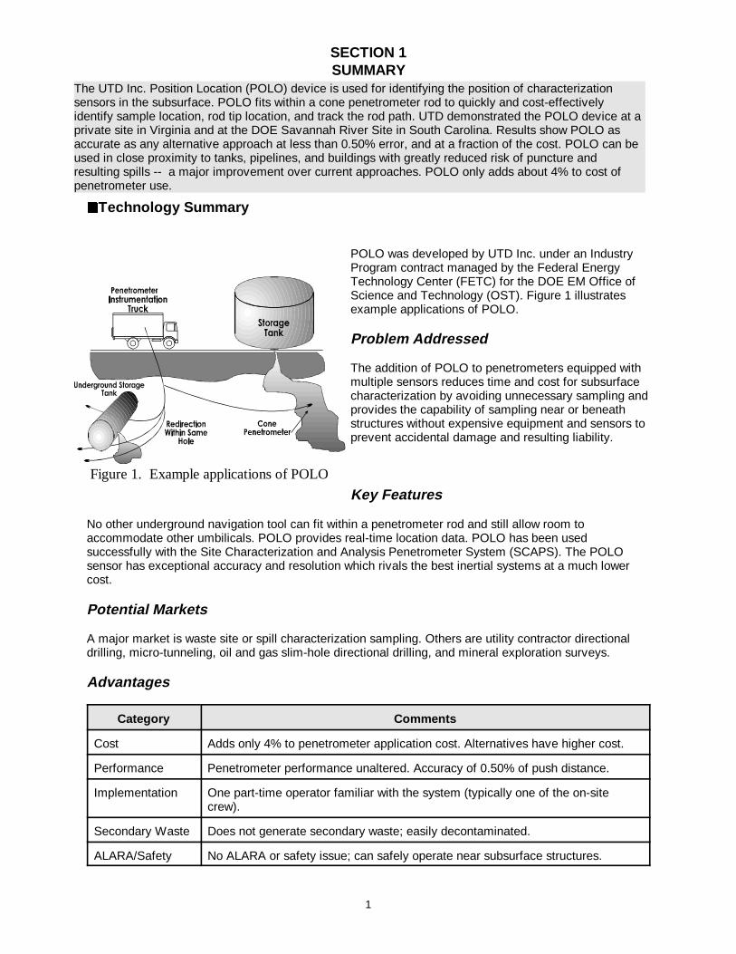
Figure 1. Example applications of POLO
SECTION 1SUMMARY
22Technology Summary
POLO was developed by UTD Inc. under an IndustryProgram contract managed by the Federal EnergyTechnology Center (FETC) for the DOE EM Office ofScience and Technology (OST). Figure 1 illustratesexample applications of POLO.
Problem Addressed
The addition of POLO to penetrometers equipped withmultiple sensors reduces time and cost for subsurfacecharacterization by avoiding unnecessary sampling andprovides the capability of sampling near or beneathstructures without expensive equipment and sensors toprevent accidental damage and resulting liability.
Key Features
No other underground navigation tool can fit within a penetrometer rod and still allow room toaccommodate other umbilicals. POLO provides real-time location data. POLO has been usedsuccessfully with the Site Characterization and Analysis Penetrometer System (SCAPS). The POLOsensor has exceptional accuracy and resolution which rivals the best inertial systems at a much lowercost.
Potential Markets
A major market is waste site or spill characterization sampling. Others are utility contractor directionaldrilling, micro-tunneling, oil and gas slim-hole directional drilling, and mineral exploration surveys.
Advantages
Category Comments
Cost Adds only 4% to penetrometer application cost. Alternatives have higher cost.
Performance Penetrometer performance unaltered. Accuracy of 0.50% of push distance.
Implementation One part-time operator familiar with the system (typically one of the on-sitecrew).
Secondary Waste Does not generate secondary waste; easily decontaminated.
ALARA/Safety No ALARA or safety issue; can safely operate near subsurface structures.
2
Limitations/Skills Required
The POLO system alone is capable of providing location of the rod tip as “pushed” and is best used whencombined with the ability to change course to target specific points underground or to avoid obstacles.This capability was developed through a second Industry Program contract. A part-time operator runs thePOLO software, monitors its function, and relays data. Some training is needed.
22Demonstration Summary
The first field demonstration was conducted at a private site in a natural deposit in normally consolidatedsandy clay soil at Kingstowne, Virginia. The second field test was in a large man-made mound of non-compacted sand to cobble size particles adjacent to the railroad tie disposal site in Area F of the DOE’sSavannah River Site (SRS) at Aiken, South Carolina. Four POLO pushes were made at each site. Theproject was completed in 1994 following these two successful demonstrations.
Key Demonstration Results
POLO location data was compared with land-surveyed locations determined using a transit, stadia rod,and tape. The difference in location of the end point of the penetrometer over the distance pushedcomprised the calculated error. Error for interim points in the penetrometer path is assumed to be lessthan error for the end point, based on penetrometer bend characteristics. For each of the eight pushes,POLO met the success criterion of less than 0.50% error. Each POLO unit is conservatively predicted tohave a useful life of over 100,000 feet of push distance. Assuming an annual utilization of 10,000 feet forten years; linear acquisition cost amortization; and annual software maintenance and calibration, thePOLO system will add just over $0.54 to the total cost of each foot pushed.
Attendees at the 1997 SCAPS Working Group meeting estimated their typical per foot rates for conepenetrometer work range between $13 and $15. The added cost of the POLO system’s real timenavigation capability is only 4%, a considerable added advantage for a small added expense. The cost-effectiveness of the POLO system is clearly demonstrated when costs of current state-of-the-artsystems, such as gyro systems, accelerometers, and flux gates, are considered along with theiraccuracy. A plot of cost versus accuracy for the baseline (unguided “point and shoot”) and state-of-the-art systems, including POLO, is presented in Section 5.
Regulator Issues
The use of the POLO system will not change the number or type of permits required. POLO does notgenerate secondary waste.
Technology Availability
A commercial POLO system (instrumented of penetrometer rod section, downhole electronics, initializer,and computer) was officially transferred to SRS for their use in 1997. UTD is developing a POLO-basedtracking system for use inside of drill strings. This activity is being co-funded by UTD and a commercialdrilling company. In addition, UTD has been marketing the POLO system to penetrometer contractors asa bend indicator warning system as well as a path tracking device. The technology developer expects tomanufacture, sell, and service POLO units.
Technology Limitations/Needs for Future Development
POLO’s benefit increases with greater length of penetrometer push. The benefit of using the POLOsystem is only fully realized when used in conjunction with UTD’s steerable penetrometer systemdeveloped under a subsequent FETC Industry Program contract, completed in 1997, and commerciallyavailable through UTD, Inc.
3
Contacts
Technical
UTD Contact:Barney Harris, (703) 339-0800E-mail: [email protected]
Management
DOE Project Manager:John R. Duda, DOE FETC, (304) 285-4217E-mail: [email protected]
Other
All published Innovative Technology Summary Reports are available at http://em-50.em.doe.gov. TheTechnology Management System, also available through the EM50 (Office of Science and Technology;OST) web site, provides information about OST programs, technologies, and problems. The OSTreference number for the Innovative Directional and Position Specific Sampling Technique (POLO) is316.
4
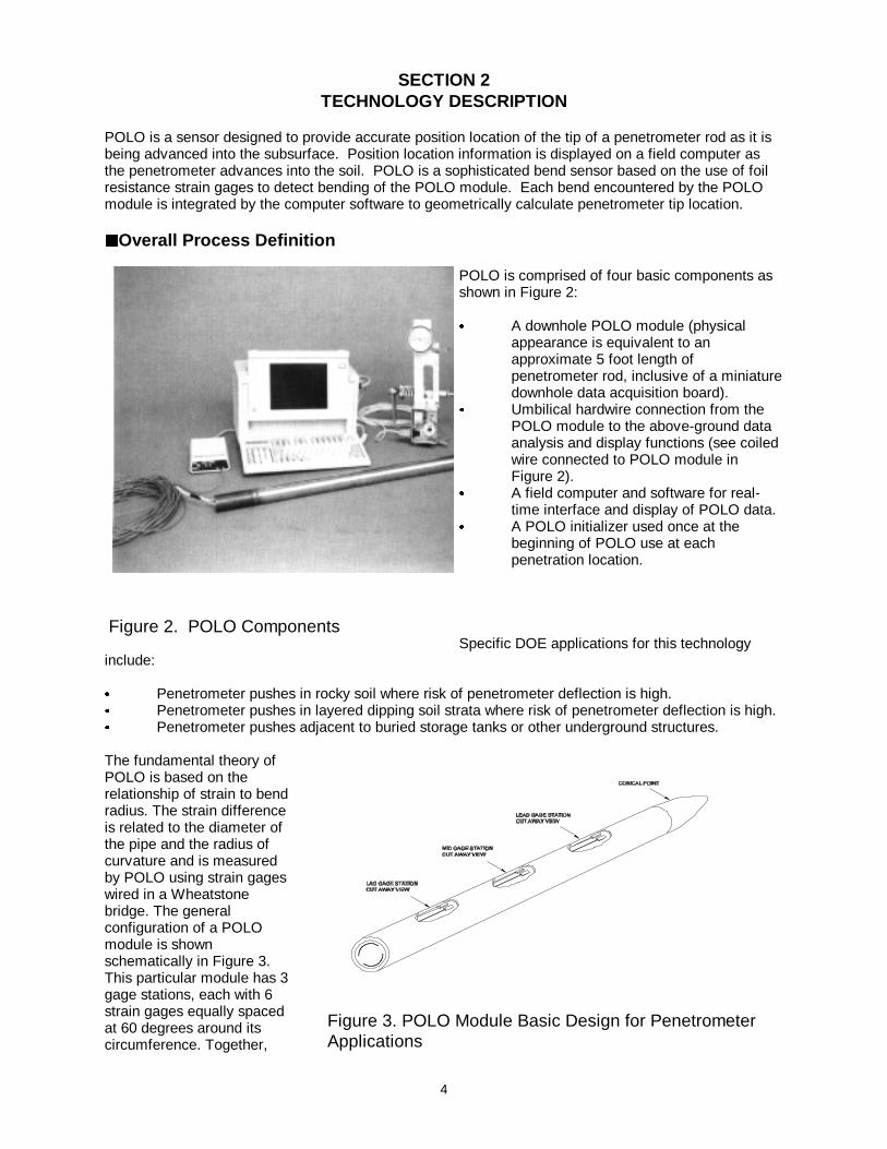
Figure 2. POLO Components
Figure 3. POLO Module Basic Design for PenetrometerApplications
SECTION 2TECHNOLOGY DESCRIPTION
POLO is a sensor designed to provide accurate position location of the tip of a penetrometer rod as it isbeing advanced into the subsurface. Position location information is displayed on a field computer asthe penetrometer advances into the soil. POLO is a sophisticated bend sensor based on the use of foilresistance strain gages to detect bending of the POLO module. Each bend encountered by the POLOmodule is integrated by the computer software to geometrically calculate penetrometer tip location.
22Overall Process Definition
POLO is comprised of four basic components asshown in Figure 2:
& A downhole POLO module (physicalappearance is equivalent to anapproximate 5 foot length ofpenetrometer rod, inclusive of a miniaturedownhole data acquisition board).
& Umbilical hardwire connection from thePOLO module to the above-ground dataanalysis and display functions (see coiledwire connected to POLO module inFigure 2).
& A field computer and software for real-time interface and display of POLO data.
& A POLO initializer used once at thebeginning of POLO use at eachpenetration location.
Specific DOE applications for this technologyinclude:
& Penetrometer pushes in rocky soil where risk of penetrometer deflection is high.& Penetrometer pushes in layered dipping soil strata where risk of penetrometer deflection is high.& Penetrometer pushes adjacent to buried storage tanks or other underground structures.
The fundamental theory ofPOLO is based on therelationship of strain to bendradius. The strain differenceis related to the diameter ofthe pipe and the radius ofcurvature and is measuredby POLO using strain gageswired in a Wheatstonebridge. The generalconfiguration of a POLOmodule is shownschematically in Figure 3.This particular module has 3gage stations, each with 6strain gages equally spacedat 60 degrees around itscircumference. Together,
5
BHKS74
VERTICAL
MODULEROTATIONANGLE
POLO
a ANGLE
AZIMUTH
D
C
A
F
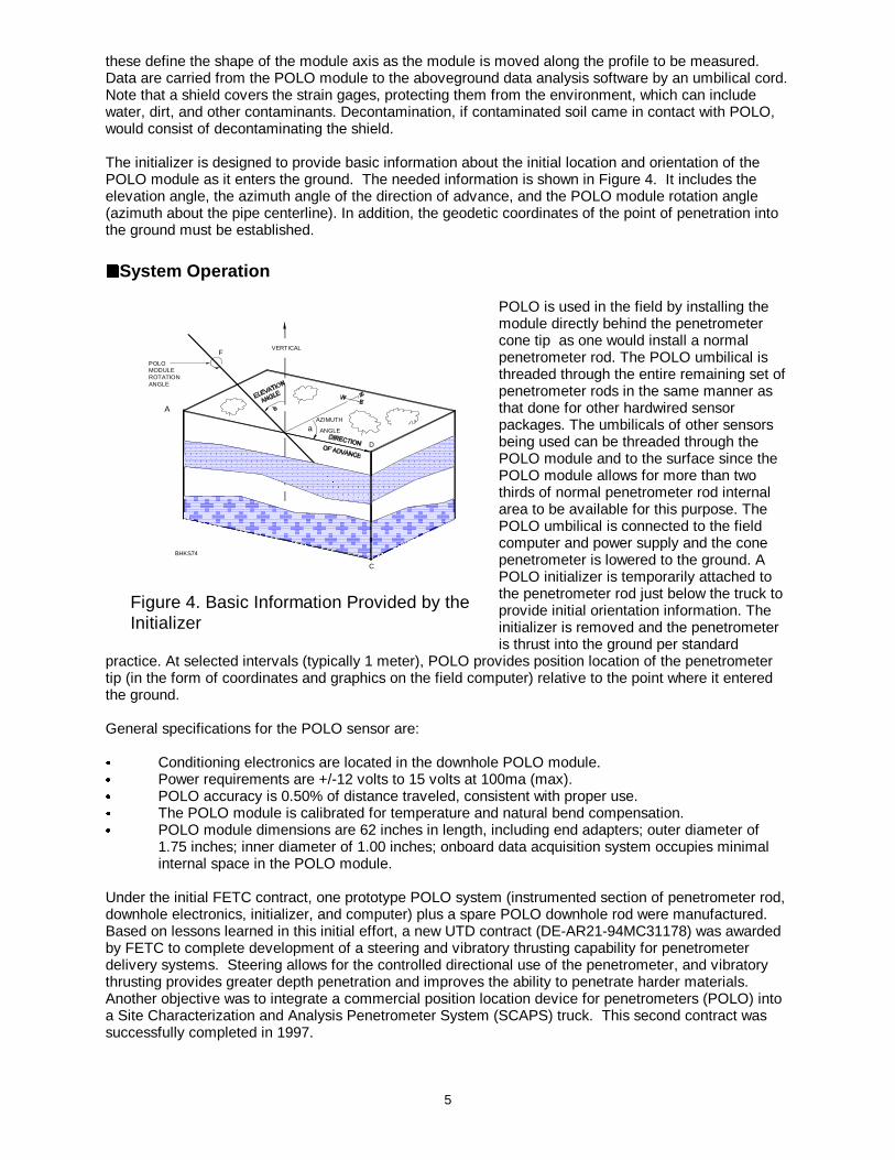
Figure 4. Basic Information Provided by theInitializer
these define the shape of the module axis as the module is moved along the profile to be measured.Data are carried from the POLO module to the aboveground data analysis software by an umbilical cord.Note that a shield covers the strain gages, protecting them from the environment, which can includewater, dirt, and other contaminants. Decontamination, if contaminated soil came in contact with POLO,would consist of decontaminating the shield.
The initializer is designed to provide basic information about the initial location and orientation of thePOLO module as it enters the ground. The needed information is shown in Figure 4. It includes theelevation angle, the azimuth angle of the direction of advance, and the POLO module rotation angle(azimuth about the pipe centerline). In addition, the geodetic coordinates of the point of penetration intothe ground must be established.
22System Operation
POLO is used in the field by installing themodule directly behind the penetrometercone tip as one would install a normalpenetrometer rod. The POLO umbilical isthreaded through the entire remaining set ofpenetrometer rods in the same manner asthat done for other hardwired sensorpackages. The umbilicals of other sensorsbeing used can be threaded through thePOLO module and to the surface since thePOLO module allows for more than twothirds of normal penetrometer rod internalarea to be available for this purpose. ThePOLO umbilical is connected to the fieldcomputer and power supply and the conepenetrometer is lowered to the ground. APOLO initializer is temporarily attached tothe penetrometer rod just below the truck toprovide initial orientation information. Theinitializer is removed and the penetrometeris thrust into the ground per standard
practice. At selected intervals (typically 1 meter), POLO provides position location of the penetrometertip (in the form of coordinates and graphics on the field computer) relative to the point where it enteredthe ground.
General specifications for the POLO sensor are:
& Conditioning electronics are located in the downhole POLO module.& Power requirements are +/-12 volts to 15 volts at 100ma (max).& POLO accuracy is 0.50% of distance traveled, consistent with proper use.& The POLO module is calibrated for temperature and natural bend compensation.& POLO module dimensions are 62 inches in length, including end adapters; outer diameter of
1.75 inches; inner diameter of 1.00 inches; onboard data acquisition system occupies minimalinternal space in the POLO module.
Under the initial FETC contract, one prototype POLO system (instrumented section of penetrometer rod,downhole electronics, initializer, and computer) plus a spare POLO downhole rod were manufactured. Based on lessons learned in this initial effort, a new UTD contract (DE-AR21-94MC31178) was awardedby FETC to complete development of a steering and vibratory thrusting capability for penetrometerdelivery systems. Steering allows for the controlled directional use of the penetrometer, and vibratorythrusting provides greater depth penetration and improves the ability to penetrate harder materials. Another objective was to integrate a commercial position location device for penetrometers (POLO) intoa Site Characterization and Analysis Penetrometer System (SCAPS) truck. This second contract wassuccessfully completed in 1997.

6
The strain-gaged rod and the tracking algorithm, which are the heart of the POLO system have beenpatented. A complete POLO system was officially transferred to SRS for their use in 1997.
7
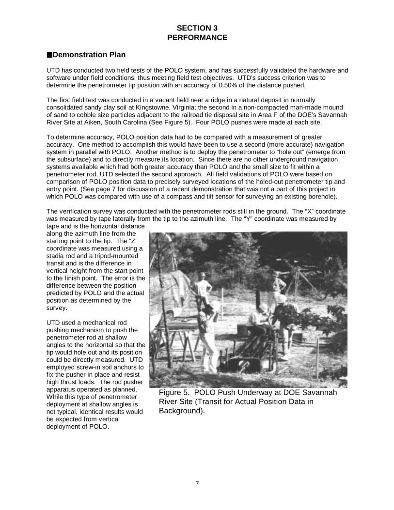
Figure 5. POLO Push Underway at DOE SavannahRiver Site (Transit for Actual Position Data inBackground).
SECTION 3PERFORMANCE
22Demonstration Plan
UTD has conducted two field tests of the POLO system, and has successfully validated the hardware andsoftware under field conditions, thus meeting field test objectives. UTD’s success criterion was todetermine the penetrometer tip position with an accuracy of 0.50% of the distance pushed.
The first field test was conducted in a vacant field near a ridge in a natural deposit in normallyconsolidated sandy clay soil at Kingstowne, Virginia; the second in a non-compacted man-made moundof sand to cobble size particles adjacent to the railroad tie disposal site in Area F of the DOE’s SavannahRiver Site at Aiken, South Carolina (See Figure 5). Four POLO pushes were made at each site.
To determine accuracy, POLO position data had to be compared with a measurement of greateraccuracy. One method to accomplish this would have been to use a second (more accurate) navigationsystem in parallel with POLO. Another method is to deploy the penetrometer to “hole out” (emerge fromthe subsurface) and to directly measure its location. Since there are no other underground navigationsystems available which had both greater accuracy than POLO and the small size to fit within apenetrometer rod, UTD selected the second approach. All field validations of POLO were based oncomparison of POLO position data to precisely surveyed locations of the holed-out penetrometer tip andentry point. (See page 7 for discussion of a recent demonstration that was not a part of this project inwhich POLO was compared with use of a compass and tilt sensor for surveying an existing borehole).
The verification survey was conducted with the penetrometer rods still in the ground. The “X” coordinatewas measured by tape laterally from the tip to the azimuth line. The “Y” coordinate was measured bytape and is the horizontal distancealong the azimuth line from thestarting point to the tip. The “Z”coordinate was measured using astadia rod and a tripod-mountedtransit and is the difference invertical height from the start pointto the finish point. The error is thedifference between the positionpredicted by POLO and the actualposition as determined by thesurvey.
UTD used a mechanical rodpushing mechanism to push thepenetrometer rod at shallowangles to the horizontal so that thetip would hole out and its positioncould be directly measured. UTDemployed screw-in soil anchors tofix the pusher in place and resisthigh thrust loads. The rod pusherapparatus operated as planned. While this type of penetrometerdeployment at shallow angles isnot typical, identical results wouldbe expected from verticaldeployment of POLO.
8
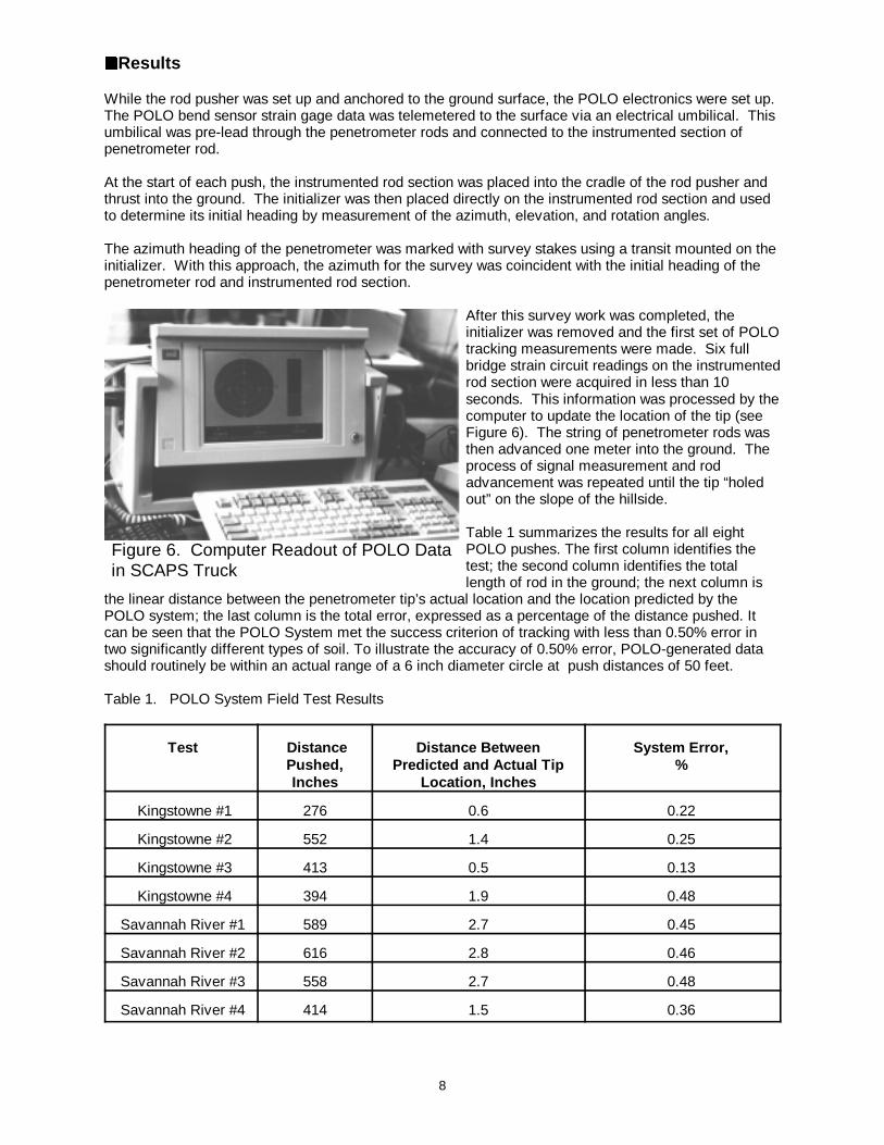
Figure 6. Computer Readout of POLO Datain SCAPS Truck
22Results
While the rod pusher was set up and anchored to the ground surface, the POLO electronics were set up. The POLO bend sensor strain gage data was telemetered to the surface via an electrical umbilical. Thisumbilical was pre-lead through the penetrometer rods and connected to the instrumented section ofpenetrometer rod.
At the start of each push, the instrumented rod section was placed into the cradle of the rod pusher andthrust into the ground. The initializer was then placed directly on the instrumented rod section and usedto determine its initial heading by measurement of the azimuth, elevation, and rotation angles.
The azimuth heading of the penetrometer was marked with survey stakes using a transit mounted on theinitializer. With this approach, the azimuth for the survey was coincident with the initial heading of thepenetrometer rod and instrumented rod section.
After this survey work was completed, theinitializer was removed and the first set of POLOtracking measurements were made. Six fullbridge strain circuit readings on the instrumentedrod section were acquired in less than 10seconds. This information was processed by thecomputer to update the location of the tip (seeFigure 6). The string of penetrometer rods wasthen advanced one meter into the ground. Theprocess of signal measurement and rodadvancement was repeated until the tip “holedout” on the slope of the hillside.
Table 1 summarizes the results for all eightPOLO pushes. The first column identifies thetest; the second column identifies the totallength of rod in the ground; the next column is
the linear distance between the penetrometer tip’s actual location and the location predicted by thePOLO system; the last column is the total error, expressed as a percentage of the distance pushed. Itcan be seen that the POLO System met the success criterion of tracking with less than 0.50% error intwo significantly different types of soil. To illustrate the accuracy of 0.50% error, POLO-generated datashould routinely be within an actual range of a 6 inch diameter circle at push distances of 50 feet.
Table 1. POLO System Field Test Results
Test DistancePushed,Inches
Distance BetweenPredicted and Actual Tip
Location, Inches
System Error,%
Kingstowne #1 276 0.6 0.22
Kingstowne #2 552 1.4 0.25
Kingstowne #3 413 0.5 0.13
Kingstowne #4 394 1.9 0.48
Savannah River #1 589 2.7 0.45
Savannah River #2 616 2.8 0.46
Savannah River #3 558 2.7 0.48
Savannah River #4 414 1.5 0.36
9
Additional performance data was developed from a January 1998 field test of a POLO system modifiedfor use in the survey of drill strings. This demonstration was conducted under an agreement betweenUTD and Ontario Hydro Technologies, and involved no DOE sponsorship. For an 1,800 foot long coreboring, primary means of survey consisted of sending a compass with a tilt sensor downhole andphotographing their readings. The negatives were processed at the site and the compass and tilt anglereadings were used to calculate coordinates on a point and slope basis. This method represents astandard of high accuracy against which other methods, such as POLO, can be compared.
At 1,710 feet (last point surveyed by POLO), the lateral deviation between POLO position data and theprimary survey data was 8.3 feet. This is equal to 0.48% error as a function of the traveled distance of1,710 feet. The survey time using POLO took 20 minutes to push the device down the hole and 10minutes to pull it back to the surface. Data transfer and path calculations took an additional 10 minutesto complete.
10
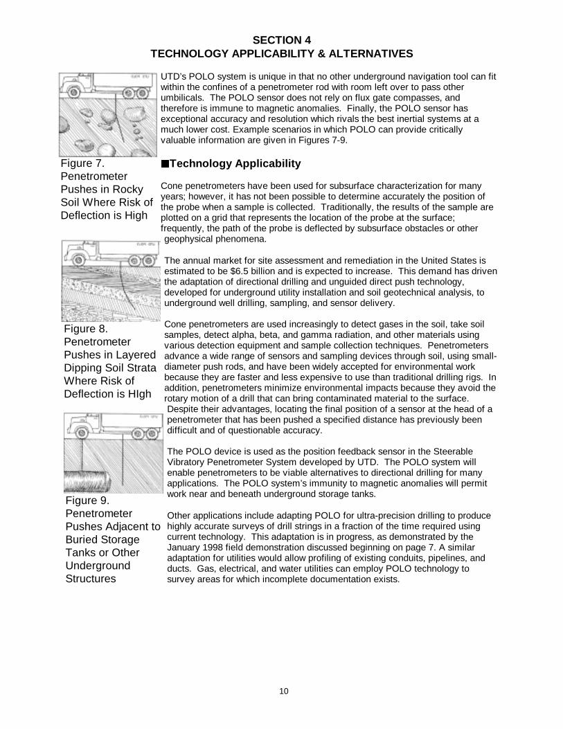
Figure 7. PenetrometerPushes in RockySoil Where Risk ofDeflection is High
Figure 8. PenetrometerPushes in LayeredDipping Soil StrataWhere Risk ofDeflection is HIgh
Figure 9. PenetrometerPushes Adjacent toBuried StorageTanks or OtherUndergroundStructures
SECTION 4TECHNOLOGY APPLICABILITY & ALTERNATIVES
UTD’s POLO system is unique in that no other underground navigation tool can fitwithin the confines of a penetrometer rod with room left over to pass otherumbilicals. The POLO sensor does not rely on flux gate compasses, andtherefore is immune to magnetic anomalies. Finally, the POLO sensor hasexceptional accuracy and resolution which rivals the best inertial systems at amuch lower cost. Example scenarios in which POLO can provide criticallyvaluable information are given in Figures 7-9.
22Technology Applicability
Cone penetrometers have been used for subsurface characterization for manyyears; however, it has not been possible to determine accurately the position ofthe probe when a sample is collected. Traditionally, the results of the sample areplotted on a grid that represents the location of the probe at the surface;frequently, the path of the probe is deflected by subsurface obstacles or othergeophysical phenomena.
The annual market for site assessment and remediation in the United States isestimated to be $6.5 billion and is expected to increase. This demand has driventhe adaptation of directional drilling and unguided direct push technology,developed for underground utility installation and soil geotechnical analysis, tounderground well drilling, sampling, and sensor delivery.
Cone penetrometers are used increasingly to detect gases in the soil, take soilsamples, detect alpha, beta, and gamma radiation, and other materials usingvarious detection equipment and sample collection techniques. Penetrometersadvance a wide range of sensors and sampling devices through soil, using small-diameter push rods, and have been widely accepted for environmental workbecause they are faster and less expensive to use than traditional drilling rigs. Inaddition, penetrometers minimize environmental impacts because they avoid therotary motion of a drill that can bring contaminated material to the surface. Despite their advantages, locating the final position of a sensor at the head of apenetrometer that has been pushed a specified distance has previously beendifficult and of questionable accuracy.
The POLO device is used as the position feedback sensor in the SteerableVibratory Penetrometer System developed by UTD. The POLO system willenable penetrometers to be viable alternatives to directional drilling for manyapplications. The POLO system’s immunity to magnetic anomalies will permitwork near and beneath underground storage tanks.
Other applications include adapting POLO for ultra-precision drilling to producehighly accurate surveys of drill strings in a fraction of the time required usingcurrent technology. This adaptation is in progress, as demonstrated by theJanuary 1998 field demonstration discussed beginning on page 7. A similaradaptation for utilities would allow profiling of existing conduits, pipelines, andducts. Gas, electrical, and water utilities can employ POLO technology tosurvey areas for which incomplete documentation exists.
11
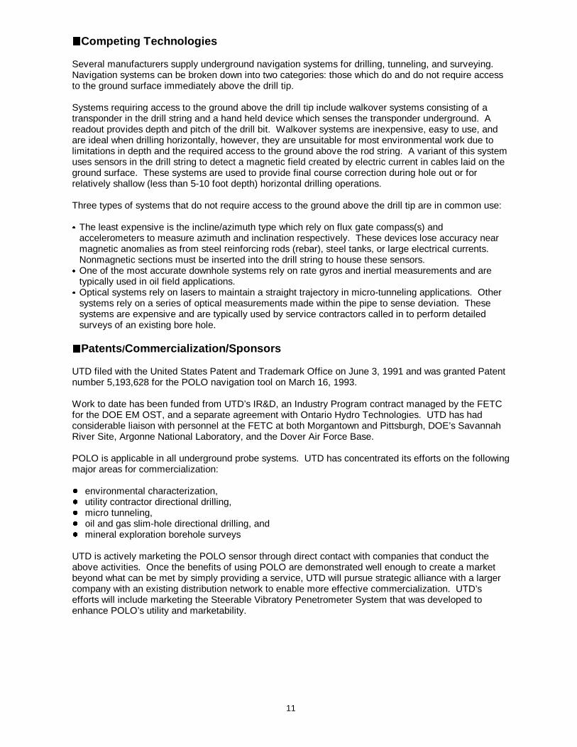
22Competing Technologies
Several manufacturers supply underground navigation systems for drilling, tunneling, and surveying. Navigation systems can be broken down into two categories: those which do and do not require accessto the ground surface immediately above the drill tip.
Systems requiring access to the ground above the drill tip include walkover systems consisting of atransponder in the drill string and a hand held device which senses the transponder underground. Areadout provides depth and pitch of the drill bit. Walkover systems are inexpensive, easy to use, andare ideal when drilling horizontally, however, they are unsuitable for most environmental work due tolimitations in depth and the required access to the ground above the rod string. A variant of this systemuses sensors in the drill string to detect a magnetic field created by electric current in cables laid on theground surface. These systems are used to provide final course correction during hole out or forrelatively shallow (less than 5-10 foot depth) horizontal drilling operations.
Three types of systems that do not require access to the ground above the drill tip are in common use:
& The least expensive is the incline/azimuth type which rely on flux gate compass(s) andaccelerometers to measure azimuth and inclination respectively. These devices lose accuracy nearmagnetic anomalies as from steel reinforcing rods (rebar), steel tanks, or large electrical currents. Nonmagnetic sections must be inserted into the drill string to house these sensors.
& One of the most accurate downhole systems rely on rate gyros and inertial measurements and aretypically used in oil field applications.
& Optical systems rely on lasers to maintain a straight trajectory in micro-tunneling applications. Othersystems rely on a series of optical measurements made within the pipe to sense deviation. Thesesystems are expensive and are typically used by service contractors called in to perform detailedsurveys of an existing bore hole.
22Patents /Commercialization/Sponsors
UTD filed with the United States Patent and Trademark Office on June 3, 1991 and was granted Patentnumber 5,193,628 for the POLO navigation tool on March 16, 1993.
Work to date has been funded from UTD’s IR&D, an Industry Program contract managed by the FETCfor the DOE EM OST, and a separate agreement with Ontario Hydro Technologies. UTD has hadconsiderable liaison with personnel at the FETC at both Morgantown and Pittsburgh, DOE’s SavannahRiver Site, Argonne National Laboratory, and the Dover Air Force Base.
POLO is applicable in all underground probe systems. UTD has concentrated its efforts on the followingmajor areas for commercialization:
� environmental characterization,� utility contractor directional drilling,� micro tunneling,� oil and gas slim-hole directional drilling, and � mineral exploration borehole surveys
UTD is actively marketing the POLO sensor through direct contact with companies that conduct theabove activities. Once the benefits of using POLO are demonstrated well enough to create a marketbeyond what can be met by simply providing a service, UTD will pursue strategic alliance with a largercompany with an existing distribution network to enable more effective commercialization. UTD’sefforts will include marketing the Steerable Vibratory Penetrometer System that was developed toenhance POLO’s utility and marketability.

12
Figure 10. Cost Comparison Between POLO andOther Navigation Systems
SECTION 5COST
22Methodology
The POLO system is used as the position feedback sensor for the steerable penetrometer systemdeveloped by UTD. At the present time, no small diameter navigation systems exist which can match
the accuracy, small size, immunity frommagnetic anomalies, and low cost of thePOLO system. While not directlycomparable due to POLO’s small size,Figure 10 presents a comparison ofnavigation devices, along withrepresentative capital costs and accuracyacquired from several manufacturers. POLO system cost estimates are based onUTD’s experience in fabricating six unitsfor research and cost projections ofhardware designed for commercialmanufacture. The relative uncertainty ofthis data is represented by the size andshape of the cost and accuracy dataranges.
22Cost Analysis
A commercial POLO system will be sold for approximately $33K. This unit will be suitable forimmediate use in a penetrometer string and will include PC based software, user manual, initializer, andall cabling. In addition, two days of training at the customer site will be required at a cost ofapproximately $1000 per day plus travel expenses. A laptop computer is required, along with powersource, and a relatively clean, dry place in which to work. The total implementation costs are presentedin Table 2.
Table 2. Implementation Cost Summary
Component or S ervice Cost Remarks
POLO System $33,000 Including downhole sensor, PC based software,user manual, initializer, and all cabling andinterfaces, one year technical support
Training $ 2,000 Conducted at user site
Travel Expenses $ 1,000 Conservatively estimated
Laptop Computer $ 3,000 Procured by end user
Battery Power Supply $ 200 Procured by end user
TOTAL CAPITAL COST $39,200
The POLO system will enable a cone penetrometer rig to effectively compete with a small directionaldrill. An illustrative example could involve sensors which must be precisely located at a typical depth of60 feet with a required precision which exceeds that available with unguided cone penetrometer rigs. Directional drills create a hole in the ground at a cost between thirty and one hundred dollars per foot. Aguided cone penetrometer rig, equipped with the POLO system, could perform the same function insubsurface conditions such as those illustrated in Figures 7-9. Based on the above, the cost of using a
13
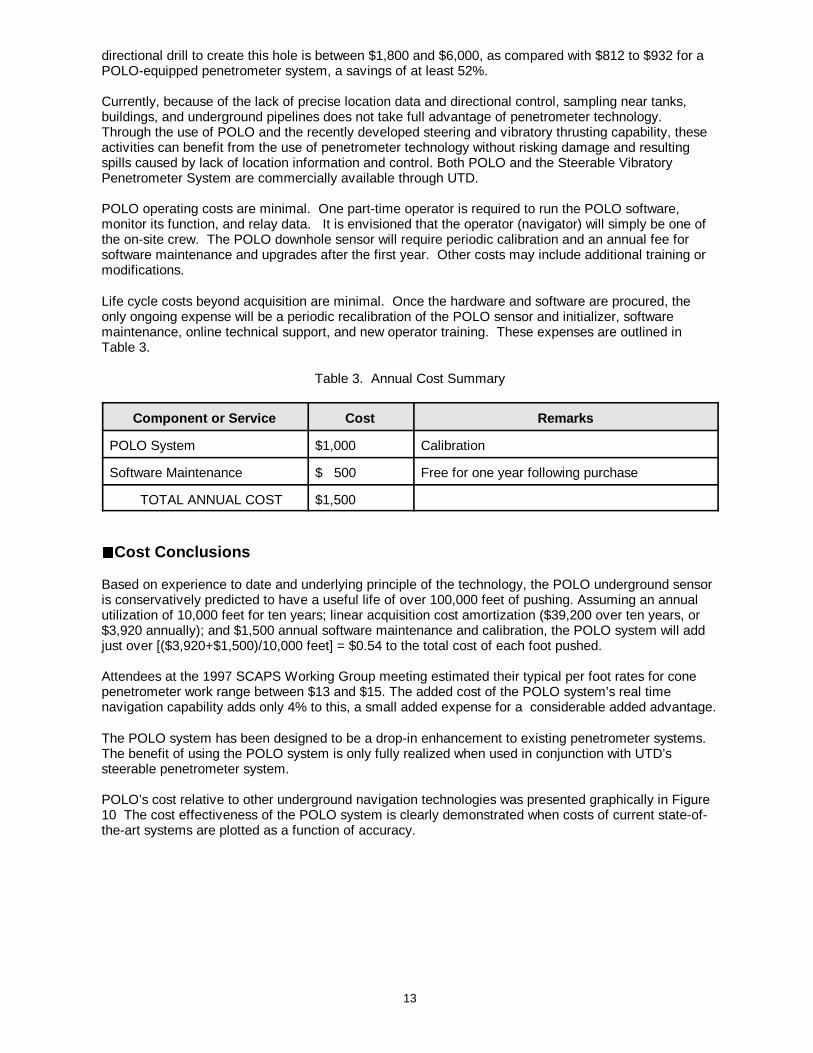
directional drill to create this hole is between $1,800 and $6,000, as compared with $812 to $932 for aPOLO-equipped penetrometer system, a savings of at least 52%.
Currently, because of the lack of precise location data and directional control, sampling near tanks,buildings, and underground pipelines does not take full advantage of penetrometer technology. Through the use of POLO and the recently developed steering and vibratory thrusting capability, theseactivities can benefit from the use of penetrometer technology without risking damage and resultingspills caused by lack of location information and control. Both POLO and the Steerable VibratoryPenetrometer System are commercially available through UTD.
POLO operating costs are minimal. One part-time operator is required to run the POLO software,monitor its function, and relay data. It is envisioned that the operator (navigator) will simply be one ofthe on-site crew. The POLO downhole sensor will require periodic calibration and an annual fee forsoftware maintenance and upgrades after the first year. Other costs may include additional training ormodifications.
Life cycle costs beyond acquisition are minimal. Once the hardware and software are procured, theonly ongoing expense will be a periodic recalibration of the POLO sensor and initializer, softwaremaintenance, online technical support, and new operator training. These expenses are outlined inTable 3.
Table 3. Annual Cost Summary
Component or S ervice Cost Remarks
POLO System $1,000 Calibration
Software Maintenance $ 500 Free for one year following purchase
TOTAL ANNUAL COST $1,500
22Cost Conclusions
Based on experience to date and underlying principle of the technology, the POLO underground sensoris conservatively predicted to have a useful life of over 100,000 feet of pushing. Assuming an annualutilization of 10,000 feet for ten years; linear acquisition cost amortization ($39,200 over ten years, or$3,920 annually); and $1,500 annual software maintenance and calibration, the POLO system will addjust over [($3,920+$1,500)/10,000 feet] = $0.54 to the total cost of each foot pushed.
Attendees at the 1997 SCAPS Working Group meeting estimated their typical per foot rates for conepenetrometer work range between $13 and $15. The added cost of the POLO system’s real timenavigation capability adds only 4% to this, a small added expense for a considerable added advantage.
The POLO system has been designed to be a drop-in enhancement to existing penetrometer systems. The benefit of using the POLO system is only fully realized when used in conjunction with UTD’ssteerable penetrometer system.
POLO’s cost relative to other underground navigation technologies was presented graphically in Figure10 The cost effectiveness of the POLO system is clearly demonstrated when costs of current state-of-the-art systems are plotted as a function of accuracy.
14
SECTION 6REGULATORY/POLICY ISSUES
22Regulatory Considerations
Cone penetrometers equipped with sensors that can detect and help quantify contamination areincreasingly used at all waste sites, including CERCLA sites, because of data collection speed and lowcost compared to drilling. POLO has the potential for further reducing time and cost by preciselylocating characterization data, thus reducing the need for collecting extra unneeded data to ensureadequate delineation and to avoid redeployment to fill data gaps. Regulatory agencies should [areexpected to] view the use of POLO as a positive development that increases the certainty that field datais truly representative of actual field conditions. The use of the POLO system with cone penetrometerswill not change the number or type of permits required for penetrometer operations. POLO does notgenerate secondary waste and will not change the total amount of secondary waste (if any) created bydirect-push penetrometers.
22Safety, Risks, Benefits, and Community Reaction
POLO is a drop-in enhancement to existing penetrometer capabilities, therefore, CERCLA evaluationcriteria are not applicable to the use of POLO.
POLO is a safety enhancement due to its accurate navigation: the POLO system will permit saferoperation probing in close proximity to storage tanks and/or pipes which contain hazardous materials. POLO reduces the risk of puncturing such structures and causing further release of contaminants to thesoil.
Advantages penetrometers have over drilling include:
� No contaminated cuttings: the hole is created by compaction - no cuttings are removed from theground or transported to other subsurface layers.
� No drill fluids: no drilling fluids are used, reducing the spread of contamination.
� Continuous data collection: nonrotating direct push technology enables on board sensors to functionwhile the penetrometer is advanced.
� Smaller hole diameter: penetrometers are typically smaller in diameter than even the smallest drills,resulting in less subsurface disturbance.
22Socioeconomic Impacts and Community Perception
POLO will have minimal impact on the labor force and economy of a given region where it is applied. The general public has minimal familiarity with the concept of underground navigation and the devicesused.

15
SECTION 7LESSONS LEARNED
POLO provides location information to 0.50% accuracy, while the baseline technology, unguided “pointand shoot”, is accurate to 5%. Problems that may be encountered vary depending on field conditionsand specific applications. For example, unguided pushes of 20 feet would routinely hit a target 2 feet indiameter which may provide acceptable accuracy, unless the push is near an underground storage tankor other structure. Other less sensitive applications may not derive substantial benefit unless pushes aregreater than 50 feet. However, the POLO system’s real time navigation capability adds only 4% to thecost of penetrometer use, a considerable advantage for small added expense.
Implementat ion Consid erat ions
The POLO system alone is only capable of providing location - and is best when combined with therecently developed ability to change course to target specific points underground or to avoid obstacles. POLO has accuracy similar to the state-of-the-art in underground navigation and has severaladvantages not available with any other system. POLO is less costly to implement than other baselinenavigation systems.
POLO was successfully tested with SCAPS and the technology developer maintains contact withSCAPS personnel. However, in spite of this, significant implementation of the technology across theDOE complex has not yet been effected. The developer continues to assess DOE opportunities/needs,and is modifying its marketing strategies in order to better deploy the technology.
Technology Limitations/ Needs for Future Deve lopment
Marketing of POLO capabilities for uses outside DOE, particularly for accurately surveying existingboreholes, appears to have gained interest. The January 1998 demonstration cited in Section 3, page7, directly compared POLO with a baseline technology with favorable results that further verified the0.50% accuracy that was a major success criterion of FETC’s Industry Programs technologydevelopment project. Presently, it is thought that additional demonstration of the integrated system(POLO and the steerable vibratory penetrometer system) are needed to more effectively penetrate theprivate sector market, and subsequently expand market share.
16
APPENDIX AREFERENCES
The references listed below are documents or contract deliverables associated with Contract DE-AC21-92MC29119 for design, development and demonstration of the POLO system.
1. Monthly Status Reports2. METC EWM Division Weekly Bullets3. Volume II, Technical Proposal, undated4. Management Plan, August 19925. Phase II Management Plan, June 19936. Phase II Draft Final Report and Phase III Technical Proposal, November 19937. Phase III Proposal Review, December 9, 19938. Phase III Management Plan, February 19949. Memorandum, S. Brett Humble and Chris Wyatt, Energetics, Inc., to Wilkins Smith, Energetics,
Inc., September 30, 1994, re: Meeting Minutes for the Phase III Review Meeting at METC,September 30, 1994
10. Task Description, December 1, 199411. Status Reports, from July 28 - August 31, 1992 through September 199412. Innovative Direct ional and Position Specific Sampling Technique . Foster, E.L. . UTD, Inc.,
Newington, VA (United States). [1994]. 10p. DOE Contract AC2192MC29119. Sup. Doc. Num.E 1.99:DE95008362. NTIS Order Number DE95008362. Primary Report Number:DOE/MC/29119--95/C0429. Source: OSTI (DOE and DOE contractors only); NTIS (PublicSales); GPO Dep. (Depository Libraries)
13. Innovative Direct ional and Position Specific Sampling Technique: Phase I; Final Report,July 28, 1992--April 28, 1993 . Hutzel, W. J.; Foster, E. L. UTD, Inc., Newington, VA (UnitedStates). Apr 1993. 34p. DOE Contract AC2192MC29119. Sup. Doc. Num. E 1.99:DE94000049. NTIS Order Number DE94000049. Primary Report Number: DOE/MC/29119--3524. Source:OSTI (DOE and DOE contractors only); NTIS (Public Sales); GPO Dep. (Depository Libraries)
14. Innovative Direct ional and Position Specific Sampling Technique. Phase 3: Final Report,July 1992--September 1994 . Hutzel, W. J.; Hill, J. L. III; Foster, E. L. UTD, Inc., Newington, VA(United States). Sep 1994. 98p. DOE Contract AC2192MC29119. Sup. Doc. Num. E1.99:DE95000006. NTIS Order Number DE95000006. Primary Report Number:DOE/MC/29119--3881. Source: OSTI (DOE and DOE contractors only); NTIS (Public Sales);GPO Dep. (Depository Libraries)
15. Innovative Direct ional and Position Specific Sampling Technique; Phase 2, Final report,[July 28, 1992--February 15, 1994] . Hutzel, W. J.; Hill, J. L. III; Foster, E. L. UTD, Inc.,Newington, VA (United States). Jan 1994. 38p. DOE Contract AC2192MC29119. Sup. Doc.Num. E 1.99:DE94004083. NTIS Order Number DE94004083. Primary Report Number:DOE/MC/29119--3667. Source: OSTI (DOE and DOE contractors only); NTIS (Public Sales);GPO Dep. (Depository Libraries)

17
16. “Cone Penetrometer,” Innovative Technology Summary Report, U.S. Department of Energy, April
1996.17. “HDD Locator Review,” article in Directional Drilling supplement to Trenchless Technology,
Volume 1, Number 2, September 1996.18. “An Introduction to Trenchless Technology,” Steven R. Kramer, William J. McDonald, James C.
Thomson, Van Nostrand Reinhold, New York, NY, 1992.19. “Cleaning up the Nation’s Waste Sites: Markets and Technology Trends, 1996 Edition,”
Environmental Protection Agency, EPA Report Number EPA-542-R-96-005.20. Product Brochures, various.
18
APPENDIX BACRONYMS AND ABBREVIATIONS
ALARA As Low As Reasonably Achievable, a measure of potential worker exposure toradiation.
CERCLA Comprehensive Environmental Response, Compensation, and Liability Act
CPT Cone Penetrometer
DOE Department of Energy
FETC Federal Energy Technology Center
IR&D Internal Research and Development
ma milliamps
NTIS National Technical Information Service
POLO Position Location
OST DOE Office of Science and Technology
rebar steel reinforcing bars embedded in concrete used to increase tensile strength
SCAPS Site Characterization and Analysis Penetrometer System, a platform with state-of-the-art sensor technology and a suite of cone penetrometer (CPT) tools.
SRS Savannah River Site