inst demu-fix 10-15 v07-17 - halfen - fixing …downloads.halfen.com/.../inst_demu-fix_10-15.pdfdemu...
TRANSCRIPT
DEMU INST_DEMU-FIX 10/15
Assembly Instructions • Montageanleitung • Notice d‘utilisation • Montagehandleiding • Instrukcja montażu
Fixing Anchors
D
Bevestigingsankers
Kotwy tulejowe
NL
PL
Douilles de fi xationsF
Hülsenanker
GB
2 © 2017 HALFEN · INST_DEMU-FIX 10/15 · www.halfen.com
DEMU Fixing Anchors Assembly instructions D
euts
chEn
glis
hFr
ança
isN
eder
land
sPo
lski
Type1988Type1985
In order to guarantee best possible bond between the fi xing anchor and the concrete, make sure that the surface of the anchor is free from dirt, oil, etc.The concrete has to be poured carefully; please avoid direct contact between the compacting device and the fi xing an-chor. Additional securing of the anchors by wire-tying is recommended.
The fi xing anchors may be embedded fl ush or recessed in the concrete. It is strongly recommended to use washers to shim if anchors are recessed.
Shortly after striking the formwork the nailing plates should be removed. The inside of the threaded socket must be
dry and further protected against ingress of water, dirt or oil until required for use i.e. for fi xing components. Ensure the inside of the socket remains dry after fi nal assembly.
The fi xing component (bolt with standard metric thread) has to be selected according to the static engineer’s specifi -cations. Minimum / maximum screw-in length for bolts and maximum installation torque moment (Tinst) can be found on pages 6 - 7. The fi xing anchor must not be subjected to full load capacity until the concrete has reached its fi nal strength.
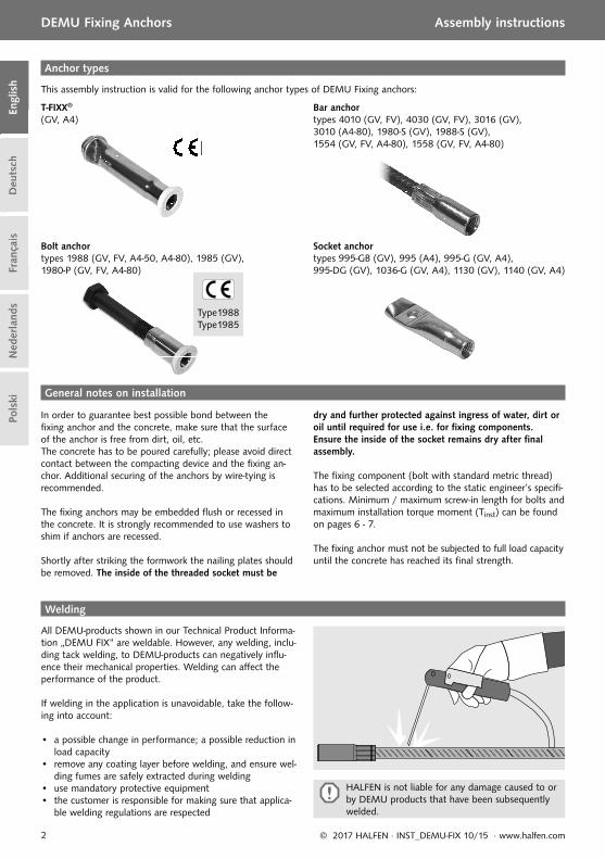
This assembly instruction is valid for the following anchor types of DEMU Fixing anchors:
All DEMU-products shown in our Technical Product Informa-tion „DEMU FIX“ are weldable. However, any welding, inclu-ding tack welding, to DEMU-products can negatively infl u-ence their mechanical properties. Welding can aff ect the performance of the product.
If welding in the application is unavoidable, take the follow-ing into account:
• a possible change in performance; a possible reduction in load capacity
• remove any coating layer before welding, and ensure wel-ding fumes are safely extracted during welding
• use mandatory protective equipment• the customer is responsible for making sure that applica-
ble welding regulations are respected
General notes on installation
Anchor types
Welding
HALFEN is not liable for any damage caused to or by DEMU products that have been subsequently welded.
T-FIXX® (GV, A4)
Bolt anchor types 1988 (GV, FV, A4-50, A4-80), 1985 (GV), 1980-P (GV, FV, A4-80)
Bar anchor types 4010 (GV, FV), 4030 (GV, FV), 3016 (GV), 3010 (A4-80), 1980-S (GV), 1988-S (GV), 1554 (GV, FV, A4-80), 1558 (GV, FV, A4-80)
Socket anchor types 995-GB (GV), 995 (A4), 995-G (GV, A4), 995-DG (GV), 1036-G (GV, A4), 1130 (GV), 1140 (GV, A4)
Deu
tsch
Era
nçai
s
g
T-FIXX®
(GV, A4)
Bolt anchor t 1988 (GV FV A4 50 A4 80types 1988 (GV, FV, A4-50, A4

3© 2017 HALFEN · INST_DEMU-FIX 10/15 · www.halfen.com
DEMU Fixing Anchors Assembly instructions
Deu
tsch
Engl
ish
Fran
çais
Ned
erla
nds
Pols
ki
dnom M6 M8 M10 M12 M16 M20 M24
∅ drilling hole [mm]
11 11 11 11 17 17 17
dnom M8* M10 M12 M16 M20 M24 M30*
* only type 2280 available
dnom M6 M8 M10 M12 M16 M20 M24 M30 M36 M42
dnom M12 M16 M20 M24 M30 M36 M42
dB fixing bolt M6 M8 M8 M10 M10 M10 M12
2280
dnom
2244
dnomdnom
2244
Thread adapter Type 2600
Available thread sizes: M12– M42
Available thread sizes: M6 – M42Sealing cap Type 2244
Assembly of accessories
Available thread sizes: M8 – M30
Available thread sizes: M6 – M24Fixing pin Type 2250
Figure 1
Figure 2
Figure 3
Figure 4
2250
dnom
2600
dnom
dBfixingbolt
Nailing plate Type 2275 (h = 2 mm)
Type 2280 (h = 10 mm)

4 © 2017 HALFEN · INST_DEMU-FIX 10/15 · www.halfen.com
DEMU Fixing Anchors Assembly instructions D
euts
chEn
glis
hFr
ança
isN
eder
land
sPo
lski
M
M
Fixing to the formwork Preparing for assembly Screw-in and fi xing of the bolt
Torque moment Tinst → see table on page 6 Bending of bolt has to be verifi ed by customer! (Bolt is not included in scope of delivery)
Case Awith plastic nailing plate
washers
washer
Assembly of nailing plate:see page 3, fi gure 1
Case Bwith plastic fi xing pin
Fixing pintype 2250
Drill hole in formwork:see page 3, fi gure 2
Case CFixing anchors with integrated nailing plate
Fixing of sealing cap:see page 3, fi gure 3
Nailing platetype 2275 or 2280
Assembly steps (shown: T-FIXX; fi xing of other anchor types analogical)
Plastic sealing cap type 2244
Remove formwork,unscrew nailing plate
Remove formwork,unscrew remainder of fixing pin
Remove formwork,remove sealing cap

5© 2017 HALFEN · INST_DEMU-FIX 10/15 · www.halfen.com
DEMU Fixing Anchors Assembly instructions
Deu
tsch
Engl
ish
Fran
çais
Ned
erla
nds
Pols
ki
a
b
cdnom dnomdB
1.
M
Fixing to the formwork Preparing for assembly Screw-in and fi xing of the bolt
Case Dwith hexagonal bolt
Torque moment Tinst → see table on page 6 Bending of bolt has to be verifi ed by customer! (Bolt is not included in scope of delivery)
Case Ewith thread adapter and hexagonal bolt
Case Fwith magnetic fi xing plate on steel formwork
Magnetic fixing plate
washers
Assembly steps (shown: T-FIXX; fi xing of other anchor types analogical)
Assembly of thread adapter: see page 3, fi gure 4
Thread adapter type 2600
a) unscrew hexagonal bolt, b) remove formwork, c) thread adapter
Unscrew hexagonal bolt,remove formwork
Remove formwork,Unscrew magnetic fixing plate

6 © 2017 HALFEN · INST_DEMU-FIX 10/15 · www.halfen.com
DEMU Fixing Anchors Assembly instructions D
euts
chEn
glis
hFr
ança
isN
eder
land
sPo
lski
Torque moment Tinst [Nm]*
Thread-size T-FIXX® Bolt anchors / Bar anchors Socket anchorsM10 ≤ 8 - ≤ 4M12 ≤ 10 ≤ 10 ≤ 8M16 ≤ 30 ≤ 30 ≤ 17M20 ≤ 60 ≤ 50 ≤ 25M24 - ≤ 90 ≤ 53M30 - ≤ 180 ≤ 96M36 - ≤ 250 -M42 - ≤ 300 -
* Tightening torque values apply only to bolts in unlubricated condition.
Minimum screw-in length s [mm]
Thread-size T-FIXX® Bolt anchor 1988 Bolt anchors 1985/1980-P / Bar anchors / Socket anchors ,
M6 - - 7.2M8 - - 9.6M10 17.0 - 12.0 / 15.0M12 20.0 16.4 14.4 / 18.0M16 26.0 21.2 19.2 / 24.0M20 32.0 26.0 24.0 / 30.0M24 - 30.8 28.8 / 36.0M30 - 38.0 36.0M36 - 45.2 43.2M42 - 52.4 50.4
value s = 1.2 × dnom higher values (s = 1.5 × dnom) apply for fixing anchors with integrated nailing plate
→ types 1985 (GV), 1036-G (GV, A4) and 1130 (GV).
Determining bolt length
General
The fi xture is attached to the cast-in anchor with a standard metric thread fastening bolt and washer or a threa-ded rod, a washer and a nut.The fi xing components are not inclu-ded with the DEMU Fixing systems and have to be ordered separately. The fi xing component (bolt) has to be selected according to the static engineer’s specifi cations.
Screw-in length of bolt
For all fi xing anchors there is a mini-mum and a maximum screw-in length. Minimum values can be found in the table below. The corresponding maximum values for each type can be found in the tables next page. To fi nd the required bolt length, proceed as described below.
Determining the required bolt length (Ls)
Bolt length (Ls)Ls,min = s + k (minimum bolt length)Ls,max = a + k (maximum bolt length)
k = clamp thickness (thickness of the steel angle support and the washers)s = minimum screw-in length (→ see table below)a = maximum screw-in length (→ see tables on page 7)
Ls,maxLs,min
a
7© 2017 HALFEN · INST_DEMU-FIX 10/15 · www.halfen.com
DEMU Fixing Anchors Assembly instructions
Deu
tsch
Engl
ish
Fran
çais
Ned
erla
nds
Pols
ki
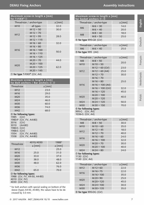
Maximum screw-in length a [mm] for T-FIXX®
Thread-size / anchor-type a [mm]M10 all types 32.0
M12
M 12 × 50 30.0M 12 × 70
28.0M 12 × 95M 12 × 115
M16
M 16 × 60 32.0M 16 × 80
50.0M 16 × 100M 16 × 110M 16 × 125
M20
M 20 × 70 44.0M 20 × 100
62.0M 20 × 125M 20 × 145
for type T-FIXX® (GV, A4)
Maximum screw-in length a [mm] for Socket anchors -
Thread-size / anchor-type a [mm]
M6M 6 × 30 14.0M 6 × 40 20.0
M8M 8 × 40 18.0M 8 × 50 25.0
for type 995-GB (GV)
Thread-size / anchor-type a [mm]M6 M 6 × 40 25.0
for type 995 (A4)
Thread-size / anchor-type a [mm]M8 M 8 × 50
20.0M10 M 10 × 50
M12M 12 × 60 (GV) 23.0M 12 × 60 (A4) 25.0M 12 × 70 30.0
M16
M 16 × 7025.0M 16 × 80
M 16 × 100 (A4)M 16 × 100 (GV) 32.0M 16 × 120 45.0
M20M 20 × 100
40.0M 20 × 120
M24 M 24 × 120 50.0M30 M 30 × 150 70.0
for following types:995-G (GV, A4)1036-G (GV, A4)
Thread-size / anchor-type a [mm]M8 M 8 × 50 30.0M10 M 10 × 60 35.0
M12M 12 × 45 18.0M 12 × 70 40.0
M16M 16 × 60 24.0M 16 × 100 32.0
M20M 20 × 70 30.0M 20 × 100 40.0
M24 M 24 × 80 24.0for following types:1130 (GV)1140 (GV, A4)
Thread-size / anchor-type a [mm]M12 M 12 × 60 22.0
M16M 16 × 75 22.0M 16 × 100 35.0
M20M 20 × 90 25.0M 20 × 120 45.0
M24 M 24 × 100 30.0M30 M 30 × 135 35.0
for type 995-DG (GV)
Maximum screw-in length a [mm] for Bolt anchors / Bar anchors , Thread-size a [mm]
M12 23.0M16 29.0M20 35.0M24 46.0M30 60.0M36 74.0M42 68.0
for following types:1985 (GV)1980-P (GV, FV, A4-80)3016 (GV)3010 (A4-80)1980-S (GV)1988-S (GV)1554 (GV, FV, A4-80)1558 (GV, FV, A4-80)
Thread-size4010/4030 1988*
a [mm] a [mm]M12 - 25.0M16 25.0 31.0M20 33.0 37.0M24 38.0 48.0M30 48.0 62.0M36 - 76.0M42 65.0 70.0
for following types:1988 (GV, FV, A4-50, A4-80)4010 (GV, FV)4030 (GV, FV)
* for bolt anchors with special sealing on bottom of the sleeve (types A4-50, A4-80), the values have to be de-creased by 3.0 mm.

8 © 2017 HALFEN · INST_DEMU-FIX 10/15 · www.halfen.com
Deu
tsch
Engl
ish
DEMU Hülsenanker Montageanleitung Fr
ança
isN
eder
land
sPo
lski
Typ1988Typ1985
Deu
tsch
Era
nçai
s
Damit ein sauberer Verbund zwischen Hülsenanker und Beton gewährleistet werden kann, ist sicherzustellen, dass der Anker nicht mit Fremdkörpern, Öl, etc. verschmutzt ist.Der Beton sollte sorgsam eingebracht werden, der direkte Kontakt zwischen Rüttler und Anker ist zu vermeiden. Zu-sätzliches Anrödeln der Anker an die Bewehrung ist zu empfehlen.Hülsenanker können oberfl ächenbündig oder vertieft einge-baut werden. Im Fall von zurückversetzt eingebauten An-kern sind bei Befestigung des Anbauteils Unterlegscheiben zur Unterfütterung zu verwenden.Unmittelbar nach dem Ausschalen sollten die Nagelteller herausgedreht werden. Das Innere der Gewindehülse hat dann bis zur Verwendung, d. h. bis zur Befestigung des
Anbauteils, gegen Eindringen von Wasser, Verunreini-gungen oder Öl geschützt zu werden und trocken zu sein. Auch nach der Endmontage ist sicherzustellen, dass kein Wasser in die Gewindehülse eindringt.Zur Befestigung des Anbauteils sind die in den Konstruk-tionsunterlagen des verantwortlichen Planers vorgeschrie-benen Schrauben zu verwenden.
Die minimalen / maximalen Einschraubtiefen der Befesti-gungsschrauben in die Gewinde hülsen sowie die maximalen Installationsdrehmomente (Tinst) sind gemäß den Tabellen auf den Seiten 12 - 13 einzuhalten. Die Belastung des Hülsenankers darf erst nach Erreichen der vorgesehenen Betonfestigkeit erfolgen.
Allgemeine Einbauhinweise
Schweißbarkeit
Alle im Katalog „DEMU FIX“ aufgeführten DEMU-Produkte (aus Stahl) sind grundsätzlich schweißbar. Allerdings kann jede Form von Schweißen, einschließlich Heftschweißen, die mechanischen Eigenschaften der DEMU-Produkte beein-trächtigen.
Sollte sich in speziellen Anwendungsfällen Schweißen nicht vermeiden lassen, so ist folgendes unbedingt zu beachten:
• Eingeschränkte Funktionsfähigkeit sowie verminderte Tragfähigkeit können eintreten.
• Evtl. vorhandene Beschichtungen sind vor dem Schwei-ßen zu entfernen; durch den Schweißvorgang auftre-tende Dämpfe sind mit geeignetem Gerät abzusaugen.
• Es ist die vorgeschriebene Schutzausrüstung zu tragen.• Der Kunde ist verantwortlich für die Einhaltung der
geltenden Vorschriften bzgl. des Schweißvorgangs.
HALFEN übernimmt keinerlei Haftung für Schäden durch DEMU-Produkte bzw. an DEMU-Produkten, die geschweißt wurden.
Diese Montageanleitung ist für folgende Ankertypen der DEMU Hülsenanker gültig:
Ankertypen
T-FIXX® (GV, A4)
Bolzenanker Typen 1988 (GV, FV, A4-50, A4-80), 1985 (GV), 1980-P (GV, FV, A4-80)
Stabanker Typen 4010 (GV, FV), 4030 (GV, FV), 3016 (GV), 3010 (A4-80), 1980-S (GV), 1988-S (GV), 1554 (GV, FV, A4-80), 1558 (GV, FV, A4-80)
Ankerhülsen Typen 995-GB (GV), 995 (A4), 995-G (GV, A4), 995-DG (GV), 1036-G (GV, A4), 1130 (GV), 1140 (GV, A4)

9© 2017 HALFEN · INST_DEMU-FIX 10/15 · www.halfen.com
Deu
tsch
Engl
ish
DEMU Hülsenanker Montageanleitung
Fran
çais
Ned
erla
nds
Pols
ki
dnom M6 M8 M10 M12 M16 M20 M24
∅ Bohrloch [mm] 11 11 11 11 17 17 17
dnom M8* M10 M12 M16 M20 M24 M30*
* nur Typ 2280 lieferbar
dnom M6 M8 M10 M12 M16 M20 M24 M30 M36 M42
dnom M12 M16 M20 M24 M30 M36 M42
dB Schraube M6 M8 M8 M10 M10 M10 M12
2280
dnom
2244
dnomdnom
2244
2250
dnom
2600
dnom
dBBefestigungs-
Schraube
Gewindeadapter Typ 2600
Verfügbare Gewindegrößen: M12– M42
Verfügbare Gewindegrößen: M6 – M42Verschlussstopfen Typ 2244
Montage des Zubehörs
Haltescheibe Typ 2275 (h = 2 mm)
Verfügbare Gewindegrößen: M8 – M30
Verfügbare Gewindegrößen: M6 – M24Montage-Bruchdübel Typ 2250
Abbildung 1
Abbildung 2
Abbildung 3
Abbildung 4
Typ 2280 (h = 10 mm)

10 © 2017 HALFEN · INST_DEMU-FIX 10/15 · www.halfen.com
Deu
tsch
Engl
ish
DEMU Hülsenanker Montageanleitung Fr
ança
isN
eder
land
sPo
lski
M
M
Schalung entfernen,Haltescheibe herausdrehen
Schalung entfernen,Gewindeteil herausdrehen
Schalung entfernen,Verschlussstopfen entfernen
Befestigung an der Schalung Vorbereitung zur Montage Schraube eindrehen und festziehen
Anzugsdrehmomente Tinst → siehe Tabelle auf Seite 12 Schraubenbiegung infolge der rückversetzten Lage des Hülsenankers ist zu berücksichtigen und bauseits
nachzuweisen (Schrauben nicht im Lieferumfang enthalten)
Fall Amit Kunststoff -Haltescheibe
Unterleg-scheiben
Unterleg-scheibe
HaltescheibeTyp 2275 oder 2280
Haltescheibe festnageln: siehe Seite 9, Abbildung 1
Fall Bmit Montage-Bruchdübel
Montage-BruchdübelTyp 2250
Bohrloch in Schalung: siehe Seite 9, Abbildung 2
Fall CHülsenanker mit integriertem Nagelfl ansch
Verschluss stopfen in Hülsenanker einsetzen: siehe Seite 9, Abbildung 3
Verschluss stopfenTyp 2244
Montagschritte (Abbildung: T-FIXX; Befestigung der anderen Hülsenakertypen analog)

11© 2017 HALFEN · INST_DEMU-FIX 10/15 · www.halfen.com
Deu
tsch
Engl
ish
DEMU Hülsenanker Montageanleitung
Fran
çais
Ned
erla
nds
Pols
ki
dnom dB a
b
c
1.
M
dnom
Befestigung an der Schalung Vorbereitung zur Montage Schraube eindrehen und festziehen
Sechskant schraube herausdrehen, Schalung entfernen
Schalung entfernen,Magnethalter herausdrehen
Fall Dmit Sechskantschraube
Anzugsdrehmomente Tinst → siehe Tabelle auf Seite 12 Schraubenbiegung infolge der rückversetzten Lage des Hülsenankers ist zu berücksichtigen und bauseits
nachzuweisen (Schrauben nicht im Lieferumfang enthalten)
Gewindeadapter fi xieren: siehe Seite 9, Abbildung 4
Fall Emit Gewindeadapter und Sechskantschraube
Fall Fmit Magnethalter auf Stahlschalung
Gewindeadapter Typ 2600
Magnethalter
a) Sechskantschraube herausdrehen, b) Schalung entfernen, c) Gewindeadapter herausdrehen
Unterleg-scheiben
Montagschritte (Abbildung: T-FIXX; Befestigung der anderen Hülsenakertypen analog)
12 © 2017 HALFEN · INST_DEMU-FIX 10/15 · www.halfen.com
Deu
tsch
Engl
ish
DEMU Hülsenanker Montageanleitung Fr
ança
isN
eder
land
sPo
lski
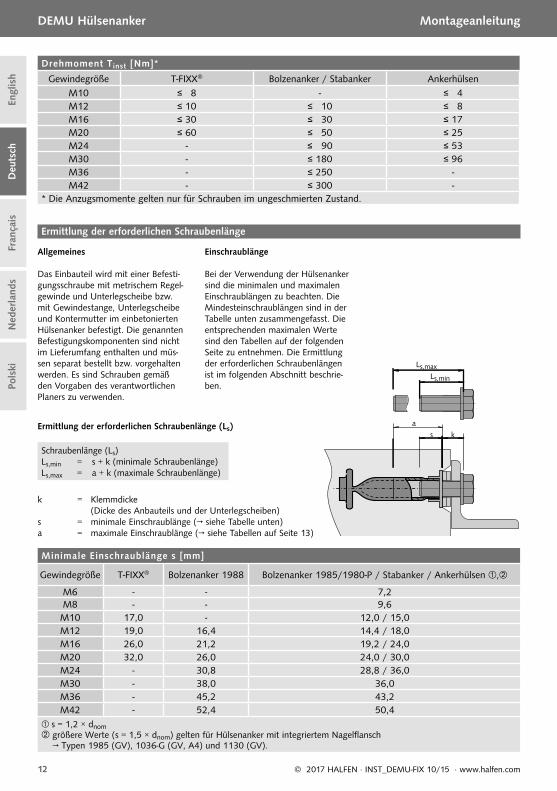
Drehmoment Tinst [Nm]*
Gewindegröße T-FIXX® Bolzenanker / Stabanker AnkerhülsenM10 ≤ 8 - ≤ 4M12 ≤ 10 ≤ 10 ≤ 8M16 ≤ 30 ≤ 30 ≤ 17M20 ≤ 60 ≤ 50 ≤ 25M24 - ≤ 90 ≤ 53M30 - ≤ 180 ≤ 96M36 - ≤ 250 -M42 - ≤ 300 -
* Die Anzugsmomente gelten nur für Schrauben im ungeschmierten Zustand.
Minimale Einschraublänge s [mm]
Gewindegröße T-FIXX® Bolzenanker 1988 Bolzenanker 1985/1980-P / Stabanker / Ankerhülsen ,
M6 - - 7,2M8 - - 9,6M10 17,0 - 12,0 / 15,0M12 19,0 16,4 14,4 / 18,0M16 26,0 21,2 19,2 / 24,0M20 32,0 26,0 24,0 / 30,0M24 - 30,8 28,8 / 36,0M30 - 38,0 36,0M36 - 45,2 43,2M42 - 52,4 50,4
s = 1,2 × dnom größere Werte (s = 1,5 × dnom) gelten für Hülsenanker mit integriertem Nagelflansch
→ Typen 1985 (GV), 1036-G (GV, A4) und 1130 (GV).
Ermittlung der erforderlichen Schraubenlänge
Allgemeines
Das Einbauteil wird mit einer Befesti-gungsschraube mit metrischem Regel-gewinde und Unterlegscheibe bzw. mit Gewindestange, Unterlegscheibe und Kontermutter im einbetonierten Hülsenanker befestigt. Die genannten Befestigungskomponenten sind nicht im Lieferumfang enthalten und müs-sen separat bestellt bzw. vorgehalten werden. Es sind Schrauben gemäß den Vorgaben des verantwortlichen Planers zu verwenden.
Einschraublänge
Bei der Verwendung der Hülsenanker sind die minimalen und maximalen Einschraublängen zu beachten. Die Mindesteinschraublängen sind in der Tabelle unten zusammengefasst. Die entsprechenden maximalen Werte sind den Tabellen auf der folgenden Seite zu entnehmen. Die Ermittlung der erforderlichen Schrauben längen ist im folgenden Abschnitt beschrie-ben.
Ermittlung der erforderlichen Schraubenlänge (Ls)
Schraubenlänge (Ls)Ls,min = s + k (minimale Schraubenlänge)Ls,max = a + k (maximale Schraubenlänge)
k = Klemmdicke (Dicke des Anbauteils und der Unterlegscheiben)s = minimale Einschraublänge (→ siehe Tabelle unten)a = maximale Einschraublänge (→ siehe Tabellen auf Seite 13)
Ls,maxLs,min
a

13© 2017 HALFEN · INST_DEMU-FIX 10/15 · www.halfen.com
Deu
tsch
Engl
ish
DEMU Hülsenanker Montageanleitung
Fran
çais
Ned
erla
nds
Pols
ki
Maximale Einschraublänge a [mm] für Ankerhülsen -Gewindegröße / Ankerabmessung a [mm]
M6M 6 × 30 14,0M 6 × 40 20,0
M8M 8 × 40 18,0M 8 × 50 25,0
für Typ 995-GB (GV)
Gewindegröße / Ankerabmessung a [mm]M6 M 6 × 40 25,0
für Typ 995 (A4)
Gewindegröße / Ankerabmessung a [mm]M8 M 8 × 50
20,0M10 M 10 × 50
M12M 12 × 60 (GV) 23,0M 12 × 60 (A4) 25,0M 12 × 70 30,0
M16
M 16 × 7025,0M 16 × 80
M 16 × 100 (A4)M 16 × 100 (GV) 32,0M 16 × 120 45,0
M20M 20 × 100
40,0M 20 × 120
M24 M 24 × 120 50,0M30 M 30 × 150 70,0
für folgende Typen:995-G (GV, A4)1036-G (GV, A4)
Gewindegröße / Ankerabmessung a [mm]M8 M 8 × 50 30,0M10 M 10 × 60 35,0
M12M 12 × 45 18,0M 12 × 70 40,0
M16M 16 × 60 24,0M 16 × 100 32,0
M20M 20 × 70 30,0M 20 × 100 40,0
M24 M 24 × 80 24,0 für folgende Typen:1130 (GV)1140 (GV, A4)
Gewindegröße / Ankerabmessung a [mm]M12 M 12 × 60 22,0
M16M 16 × 75 22,0M 16 × 100 35,0
M20M 20 × 90 25,0M 20 × 120 45,0
M24 M 24 × 100 30,0M30 M 30 × 135 35,0
für Typ 995-DG (GV)
Maximale Einschraublänge a [mm] für T-FIXX®
Gewindegröße / Ankerabmessung a [mm]M10 alle Größen 32,0
M12
M 12 × 50 30,0M 12 × 70
28,0M 12 × 95M 12 × 115
M16
M 16 × 60 32,0M 16 × 80
50,0M 16 × 100M 16 × 110M 16 × 125
M20
M 20 × 70 44,0M 20 × 100
62,0M 20 × 125M 20 × 145
für Typ T-FIXX® (GV, A4)
Maximale Einschraublänge a [mm] für Bolzenanker / Stabanker ,Gewinde-
größe a [mm]
M12 23,0M16 29,0M20 35,0M24 46,0M30 60,0M36 74,0M42 68,0
für folgende Typen:1985 (GV)1980-P (GV, FV, A4-80)3016 (GV)3010 (A4-80)1980-S (GV)1988-S (GV)1554 (GV, FV, A4-80)1558 (GV, FV, A4-80)
Gewinde-größe
4010/4030 1988*a [mm] a [mm]
M12 - 25,0M16 25,0 31,0M20 33,0 37,0M24 38,0 48,0M30 48,0 62,0M36 - 76,0M42 65,0 70,0
für folgende Typen:1988 (GV, FV, A4-50, A4-80)4010 (GV, FV)4030 (GV, FV)
* Für Bolzenanker mit versiegeltem Hülsenboden (Typen A4-50, A4-80) sind die Werte um 3 mm abzumindern.

14 © 2017 HALFEN · INST_DEMU-FIX 10/15 · www.halfen.com
Deu
tsch
Engl
ish
Fran
çais
Ned
erla
nds
DEMU Douilles de fi xations Notice d‘utilisation Po
lski
Type1988Type1985
Deu
tsch
Era
nçai
s
Afi n de garantir la meilleure adhérence possible entre la douille de fi xation et le béton, assurez vous que la surface de la douille soit propre et exempte de poussière ou d’huile.Le béton doit être coulé avec précaution, éviter le contact direct entre les douilles de fi xation et les outils de compac-tage. Nous recommandons une sécurité supplémentaire en liaisonnant solidement les douilles au coff rage.
La douille de fi xation peut être facilement noyée dans le béton. Nous recommandons fortement l’utilisation de pla-tines de fi xations ou l’un des accessoires de la page 15. Les fi xations des douilles doivent être retirées rapidement après le décoff rage.
Le fi letage intérieur de la douille doit être séché et à nouveau protégé avec un bouchon contre les agressions possibles telles que l’eau, la poussière et l’huile. Aussi après l’assemblage fi nal il faut assurer que l’intérieur de la douille reste sec.
Le boulon ou la vis (pas métrique standard) pour la fi xation de l’élément doit être choisi en fonction des calculs et des spécifi cations du bureau d’ingénierie. Les profondeurs mini-males / maximales de vissage pour les boulons et le couple de serrage (Tinst) fi gurent en pages 18-19. La douille de fi xation ne doit pas être soumise à sa capacité de charge complète avant que le béton n’ait atteint sa résis-tance fi nale.
Informations générales pour l‘utilisation
Soudure
Tous les produits DEMU dans notre catalogue technique «Douilles de fi xation DEMU» peuvent être soudés par points. Toutefois, toute soudure, notamment les soudures de positionnement, peuvent infl uencer négativement les pro-priétés mécaniques des douilles. Souder peut aff ecter les performances d’un produit.Si pour votre utilisation il est impossible d’éviter toute soudure, il faut tenir compte des éléments suivants :• une possible modifi cation des performances et une
possible réduction des capacités de charge• enlever le revêtement de protection (galva...) avant de
commencer à souder et assurez vous que les fumées de soudures sont correctement évacuées pendant la sou-dure.
• utiliser les équipements de protection appropriés le client doit s’assurer que la soudure est conforme aux recommandations réglementaires sur les soudures.
HALFEN ne pourrait être tenu responsable pour tout dommage causé à ou par des douilles DEMU qui ont été soudées.
Ces instructions d’utilisation sont valables pour les douilles de fi xation DEMU fi gurant ci-dessous :
Types de douilles
T-FIXX® (GV, A4)
Douilles à pied d’ancrage Types 1988 (GV, FV, A4-50, A4-80), 1985 (GV), 1980-P (GV, FV, A4-80)
Douilles à barre d’ancrage Types 4010 (GV, FV), 4030 (GV, FV), 3016 (GV), 3010 (A4-80), 1980-S (GV), 1988-S (GV), 1554 (GV, FV, A4-80), 1558 (GV, FV, A4-80)
Douilles de fi xation Types 995-GB (GV), 995 (A4), 995-G (GV, A4), 995-DG (GV), 1036-G (GV, A4), 1130 (GV), 1140 (GV, A4)

15© 2017 HALFEN · INST_DEMU-FIX 10/15 · www.halfen.com
Deu
tsch
Engl
ish
Fran
çais
Ned
erla
nds
DEMU Douilles de fi xations Notice d‘utilisation
Pols
ki
2280
dnom
2244
dnomdnom
2244
2250
dnom
dnom M6 M8 M10 M12 M16 M20 M24
∅ trou de perçage [mm] 11 11 11 11 17 17 17
dnom M8* M10 M12 M16 M20 M24 M30*
* seul le type 2280 est disponible
dnom M6 M8 M10 M12 M16 M20 M24 M30 M36 M42
dnom M12 M16 M20 M24 M30 M36 M42
dB diamètre de la vis M6 M8 M8 M10 M10 M10 M12
2250
dnom
2600
dnom
dBBoulon de fixation
Réducteur de fi xation Type 2600
Diamètres des fi letages disponibles : M12– M42
Diamètres des fi letages disponibles : M6 – M42Bouchon plastiqueType 2244
Utilisation des accessoires
Fixation plastique Type 2275 (h = 2 mm)
Diamètres des fi letages disponibles : M8 – M30
Diamètres des fi letages disponibles : M6 – M24Téton de fi xation Type 2250
Figure 1
Figure 2
Figure 3
Figure 4
Type 2280 (h = 10 mm)h=

16 © 2017 HALFEN · INST_DEMU-FIX 10/15 · www.halfen.com
Deu
tsch
Engl
ish
Fran
çais
Ned
erla
nds
DEMU Douilles de fi xations Notice d‘utilisation Po
lski
M
M
Fixation au coff rage Démontage pour le préparation de l’assemblage fi nal
Vissage et fi xation de la vis
Couple de serrage Tinst → voir tableau en page 18 La flexion de la vis doit être vérifiée par le client ! (La vis de fixation ne fait partie des fournitures des douilles de
fixation)
Cas Aavec fi xation en plastique à clouer
Rondelles
Rondelle
FixationType 2275 ou 2280
Mise en place de la fi xation voir page 15, fi gure 1
Cas Bavec téton de fi xation cassable
Téton de fi xation cassable Type 2250
Trou percé dans le coff rage: voir page 15, fi gure 2
Cas CDouille de fi xation avec collerette de fi xation
Fixation du bouchon d’étanchéitévoir page 15, fi gure 3
Bouchon de protection en plastiqueType 2244
Étapes de la mise en place (exemple avec T-FIXX; fi xation des autres douilles de façon identique)
Enlever le coff rage,dévisser la fi xation en plastique
Enlever le coff rage,dévisser le reste du téton
Enlever le coff rage,enlever le bouchon d’étanchéité
17© 2017 HALFEN · INST_DEMU-FIX 10/15 · www.halfen.com
Deu
tsch
Engl
ish
Fran
çais
Ned
erla
nds
DEMU Douilles de fi xations Notice d‘utilisation
Pols
ki
a
b
cdnom dB
1.
M
dnom
Fixation au coff rage Démontage pour le préparation de l’assemblage fi nal
Vissage et fi xation de la vis
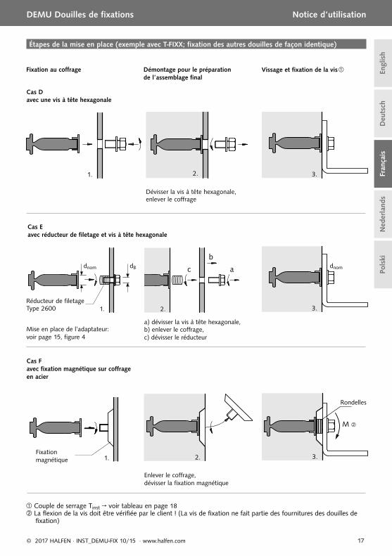
Cas Davec une vis à tête hexagonale
Couple de serrage Tinst → voir tableau en page 18 La flexion de la vis doit être vérifiée par le client ! (La vis de fixation ne fait partie des fournitures des douilles de
fixation)
Cas Eavec réducteur de fi letage et vis à tête hexagonale
Cas Favec fi xation magnétique sur coff rage en acier
Fixation magnétique
Rondelles
Étapes de la mise en place (exemple avec T-FIXX; fi xation des autres douilles de façon identique)
Dévisser la vis à tête hexagonale,enlever le coffrage
Enlever le coff rage,dévisser la fi xation magnétique
Mise en place de l’adaptateur: voir page 15, fi gure 4
Réducteur de fi letage Type 2600
a) dévisser la vis à tête hexagonale, b) enlever le coffrage, c) dévisser le réducteur

18 © 2017 HALFEN · INST_DEMU-FIX 10/15 · www.halfen.com
Deu
tsch
Engl
ish
Fran
çais
Ned
erla
nds
DEMU Douilles de fi xations Notice d‘utilisation Po
lski
Détermination de la longueur de la vis
Généralités
Les éléments de fi xation sont liaison-nés à la douille de fi xation par l’inter-médiaire d’une vis à fi letage métrique standard et de rondelles ou d’une tige fi leté, d’une rondelle et d’un écrou.Les éléments de fi xation ne font pas partis du système de fi xation DEMU et doivent être commandés séparé-ment. L’élément de fi xation (la vis) doit être choisie suivant les recom-mandations du bureau d’ingénierie.
Profondeur de vissage de la vis
Pour toutes les douilles de fi xations, il y a une profondeur de vissage mini-male et maximale. Les valeurs mini-males sont données dans le tableau ci-dessous. Les valeurs maximales cor-respondantes pour chaque modèle sont données dans les tableaux de la page suivante. Pour trouver la lon-gueur de la vis recommandée, procé-dez comme expliqué ci-dessous.
Détermination de la longueur de la vis (Ls)
Longueur de la vis (Ls)Ls,min = s + k (profondeur à visser minimale)Ls,max = a + k (profondeur à visser maximale)
k = Épaisseur à pincer (épaisseur de l’élément fi xé et des rondelles)s = profondeur à visser minimale (→ voir tableau ci-dessous)a = profondeur à visser maximale (→ voir tableau en page 19)
Ls,maxLs,min
a
Couple de serrage Tinst [Nm]*
Filetage T-FIXX® Douille à barre d’ancrage / Douille à vis d’ancrage Douille de fixation
M10 ≤ 8 - ≤ 4M12 ≤ 10 ≤ 10 ≤ 8M16 ≤ 30 ≤ 30 ≤ 17M20 ≤ 60 ≤ 50 ≤ 25M24 - ≤ 90 ≤ 53M30 - ≤ 180 ≤ 96M36 - ≤ 250 -M42 - ≤ 300 -
* Les couples de serrage sont uniquement valables pour des boulons non lubrifiés.
Profondeurs de vissage minimales s [mm]
Filetage T-FIXX® Douille de fixation 1988
Douille de fixation 1985/1980-P / Douille à barre d’ancrage / Douille à vis d’ancrage ,
M6 - - 7,2M8 - - 9,6M10 17,0 - 12,0 / 15,0M12 20,0 16,4 14,4 / 18,0M16 26,0 21,2 19,2 / 24,0M20 32,0 26,0 24,0 / 30,0M24 - 30,8 28,8 / 36,0M30 - 38,0 36,0M36 - 45,2 43,2M42 - 52,4 50,4
s = 1,2 × dnom Des valeurs plus importantes (s = 1,5 × dnom) s’appliquent pour des douilles avec une collerette de fixation
→ types 1985 (GV), 1036-G (GV, A4) et 1130 (GV).
19© 2017 HALFEN · INST_DEMU-FIX 10/15 · www.halfen.com
Deu
tsch
Engl
ish
Fran
çais
Ned
erla
nds
DEMU Douilles de fi xations Notice d‘utilisation
Pols
ki
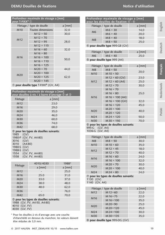
Profondeur maximale de vissage a [mm] pour les douilles de fixation -
Filetage / type de douille a [mm]
M6M 6 × 30 14,0M 6 × 40 20,0
M8M 8 × 40 18,0M 8 × 50 25,0
pour douille type 995-GB (GV)
Filetage / type de douille a [mm]M6 M 6 × 40 25,0
pour douille type 995 (A4)
Filetage / type de douille a [mm]M8 M 8 × 50
20,0M10 M 10 × 50
M12M 12 × 60 (GV) 23,0M 12 × 60 (A4) 25,0M 12 × 70 30,0
M16
M 16 × 7025,0M 16 × 80
M 16 × 100 (A4)M 16 × 100 (GV) 32,0M 16 × 120 45,0
M20M 20 × 100
40,0M 20 × 120
M24 M 24 × 120 50,0M30 M 30 × 150 70,0
pour les types de douilles suivants:995-G (GV, A4)1036-G (GV, A4)
Filetage / type de douille a [mm]M8 M 8 × 50 30,0M10 M 10 × 60 35,0
M12M 12 × 45 18,0M 12 × 70 40,0
M16M 16 × 60 24,0M 16 × 100 32,0
M20M 20 × 70 30,0M 20 × 100 40,0
M24 M 24 × 80 24,0 pour les types de douilles suivants:1130 (GV)1140 (GV, A4)
Filetage / type de douille a [mm]M12 M 12 × 60 22,0
M16M 16 × 75 22,0M 16 × 100 35,0
M20M 20 × 90 25,0M 20 × 120 45,0
M24 M 24 × 100 30,0M30 M 30 × 135 35,0
pour douille type 995-DG (GV)
Profondeur maximale de vissage a [mm] pour T-FIXX®
Filetage / type de douille a [mm]M10 Toutes dimensions 32,0
M12
M 12 × 50 30,0M 12 × 70
28,0M 12 × 95M 12 × 115
M16
M 16 × 60 32,0M 16 × 80
50,0M 16 × 100M 16 × 110M 16 × 125
M20
M 20 × 70 44,0M 20 × 100
62,0M 20 × 125M 20 × 145
pour douille type T-FIXX® (GV, A4)
Profondeur maximale de vissage a [mm] pour douilles à vis / à barre d’ancrage et
Filetage a [mm]
M12 23,0M16 29,0M20 35,0M24 46,0M30 60,0M36 74,0M42 68,0
pour les types de douilles suivants:1985 (GV)1980-P (GV, FV, A4-80)3016 (GV)3010 (A4-80)1980-S (GV)1988-S (GV)1554 (GV, FV, A4-80)1558 (GV, FV, A4-80)
Filetage4010/4030 1988*
a [mm] a [mm]M12 - 25,0M16 25.0 31,0M20 33.0 37,0M24 38.0 48,0M30 48.0 62,0M36 - 76,0M42 65.0 70,0
pour les types de douilles suivants:1988 (GV, FV, A4-50, A4-80)4010 (GV, FV)4030 (GV, FV)
* Pour les douilles à vis d‘ancrage avec une couche d’étanchéité en dessous du manchon, les valeurs doivent être réduites de 3,0 mm.

20 © 2017 HALFEN · INST_DEMU-FIX 10/15 · www.halfen.com
Deu
tsch
Engl
ish
Fran
çais
Ned
erla
nds
DEMU Bevestigingsankers Montagehandleiding Po
lski
type1988type1985
Deu
tsch
Era
nçai
s
Zorg ervoor dat het oppervlak van het anker vrij is van vuil, olie, etc. om de optimale binding tussen bevestigings-anker en beton te garanderen.Het beton moet zorgvuldig worden gestort; vermijd direct contact tussen verdichtingsapparatuur en bevestigings-anker. Extra vastzetten van de ankers aan de wapening wordt aanbevolen.Bevestigingsankers kunnen gelijk met het oppervlak of verdiept worden ingebouwd. Bij verdiept ingebouwde ankers moeten sluitringen worden gebruikt ter onder-steuning.Direct na het ontkisten dienen de spijkerplaten te worden verwijderd. De binnenzijde van de draadbus dient na het ontkisten verder te worden beschermd tegen indringen
van water, vuil of olie tot het moment van bevestigen. Ook na de montage dient de binnenzijde van de draadbus te worden beschermd tegen indringen van water.De bevestigingsbout moet worden gekozen op basis van de statische specifi caties van de constructeur.
Minimale/maximale indraailengte(s) voor bevestigings-bouten en maximale aandraaimoment (Tinst) zijn te vinden in de tabellen op pag. 24 - 25.
Het bevestigingsanker mag niet op zijn volledige capaciteit worden belast voordat het beton de vereiste sterkte bereikt heeft.
Algemene inbouw-instructies
Lassen
Alle stalen producten in de technische documentatie (DEMU FIX) zijn lasbaar. Echter kan lassen, ook hechtlassen, de mechanische eigenschappen van de DEMU-producten negatief beïnvloeden.
Indien lassen in de toepassing onvermijdelijk is, dient rekening te worden gehouden met het volgende:
• een mogelijke reductie van belastbaarheid en wijziging van gebruikseigenschappen.
• verwijder de eventueel aanwezige coatinglaag voor het lassen en zorg ervoor dat lasdampen veilig worden afgezogen.
• gebruik voorgeschreven beschermingsmiddelen.• de klant is verantwoordelijk voor naleving van de
geldende lasvoorschriften.
HALFEN is niet aansprakelijk voor eventuele schade ontstaan aan of door DEMU-producten waaraan gelast is.
Deze montagehandleiding geldt voor de volgende DEMU bevestigingsankers:
Anker types
T-FIXX® (GV, A4)
Boutanker types 1988 (GV, FV, A4-50, A4-80), 1985 (GV), 1980-P (GV, FV, A4-80)
Stekanker, staafanker types 4010 (GV, FV), 4030 (GV, FV), 3016 (GV), 3010 (A4-80), 1980-S (GV), 1988-S (GV), 1554 (GV, FV, A4-80), 1558 (GV, FV, A4-80)
Betonschroefhuls types 995-GB (GV), 995 (A4), 995-G (GV, A4), 995-DG (GV), 1036-G (GV, A4), 1130 (GV), 1140 (GV, A4)

21© 2017 HALFEN · INST_DEMU-FIX 10/15 · www.halfen.com
Deu
tsch
Engl
ish
Fran
çais
Ned
erla
nds
DEMU Bevestigingsankers Montagehandleiding
Pols
ki
dnom M6 M8 M10 M12 M16 M20 M24
∅ boorgat [mm] 11 11 11 11 17 17 17
dnom M8* M10 M12 M16 M20 M24 M30*
* alleen type 2280 beschikbaar
dnom M6 M8 M10 M12 M16 M20 M24 M30 M36 M42
dnom M12 M16 M20 M24 M30 M36 M42
dB bevesti-gingsbout M6 M8 M8 M10 M10 M10 M12
2280
dnom
2244
dnomdnom
2244
2250
dnom
2600
dnom
dBbevestigings-
bout
Montagenippeltype 2600
Beschikbare diameter schroefdraad: M12– M42
Beschikbare diameter schroefdraad: M6 – M42Afsluitdoptype 2244
Montage van accessoires
Flensplaat type 2275 (h = 2 mm)
Beschikbare diameter schroefdraad: M8 – M30
Beschikbare diameter schroefdraad: M6 – M24Breekpen type 2250
Afbeelding 1
Afbeelding 2
Afbeelding 3
Afbeelding 4
type 2280 (h = 10 mm)

22 © 2017 HALFEN · INST_DEMU-FIX 10/15 · www.halfen.com
Deu
tsch
Engl
ish
Fran
çais
Ned
erla
nds
DEMU Bevestigingsankers Montagehandleiding Po
lski
M
M
Bevestiging aan de bekisting Voorbereiding voor montage Montage van de bout
Moment Tinst → zie tabel op pag. 24 Buiging van de bout moet door de klant worden gecontroleerd (bout is niet bij de levering inbegrepen)
Voorbeeld Amet kunststof fl ensplaat
Sluitring
Sluitring
Flensplaattype 2275 of 2280
Montage van fl ensplaat: zie pag. 21, afbeelding 1
Voorbeeld Bmet kunststof breekpen
Montage breekpentype 2250
Boorgat in bekisting: zie pag. 21, afbeelding 2
Voorbeeld CBevestigingsanker met fl ensplaat
Bevestiging van afsluitdop: zie pag. 21, afbeelding 3
Kunststof afsluitdoptype 2244
Montage in stappen (T-FIXX afgebeeld; bevestiging van de andere bevestigingsankers analoog)
Bekisting verwijderen,fl ensplaat losdraaien
Bekisting verwijderen,restant van breekpen losdraaien
Bekisting verwijderen,afsluitdop verwijderen

23© 2017 HALFEN · INST_DEMU-FIX 10/15 · www.halfen.com
Deu
tsch
Engl
ish
Fran
çais
Ned
erla
nds
DEMU Bevestigingsankers Montagehandleiding
Pols
ki
a
b
cdnom dB
1.
M
dnom
Bevestiging aan de bekisting Voorbereiding voor montage Montage van de bout
Voorbeeld Dmet zeskantbout
Moment Tinst → zie tabel op pag. 24 Buiging van de bout moet door de klant worden gecontroleerd (bout is niet bij de levering inbegrepen)
Voorbeeld Emet montagenippel en zeskantbout
Voorbeeld Fmet magnetische fl ensplaat aan stalen bekisting
Magnetische fl ensplaat
Sluitring
Montage in stappen (T-FIXX afgebeeld; bevestiging van de andere bevestigingsankers analoog)
Zeskantbout losdraaien,bekisting verwijderen
Bekisting verwijderen,magnetische fl ensplaat losdraaien
Montage van montagenippel: zie pag. 21, afbeelding 4
Montagenippeltype 2600
a) Zeskantbout losdraaien, b) bekisting verwijderen,c) montagenippel losdraaien

24 © 2017 HALFEN · INST_DEMU-FIX 10/15 · www.halfen.com
Deu
tsch
Engl
ish
Fran
çais
Ned
erla
nds
DEMU Bevestigingsankers Montagehandleiding Po
lski
Aandraaimoment Tinst [Nm]*
Draaddiameter T-FIXX® Boutanker / Stekanker SchroefhulsM10 ≤ 8 - ≤ 4M12 ≤ 10 ≤ 10 ≤ 8M16 ≤ 30 ≤ 30 ≤ 17M20 ≤ 60 ≤ 50 ≤ 25M24 - ≤ 90 ≤ 53M30 - ≤ 180 ≤ 96M36 - ≤ 250 -M42 - ≤ 300 -
* De aandraaimomenten gelden alleen voor bouten die niet voorzien zijn van vet.
Minimale indraailengte s [mm]
Draaddiameter T-FIXX® Boutanker 1988 Boutanker 1985/1980-P / Stekanker / Schroefhuls ,
M6 - - 7,2M8 - - 9,6M10 17,0 - 12,0 / 15,0M12 20,0 16,4 14,4 / 18,0M16 26,0 21,2 19,2 / 24,0M20 32,0 26,0 24,0 / 30,0M24 - 30,8 28,8 / 36,0M30 - 38,0 36,0M36 - 45,2 43,2M42 - 52,4 50,4
s = 1,2 × dnom voor de bevestigingsankers met flensplaat gelden hogere waarden (s = 1,5 × dnom)
→ bevestigingsankers types 1985 (GV), 1036-G (GV, A4) en 1130 (GV).
Het bepalen van de boutlengte
Algemene informatie
De te bevestigen constructie is aan het ingebouwde anker bevestigd met een bevestigingsbout met standaard metrische draad en sluitring of met een draadstang, sluitring en moer. De bevestigingsonderdelen zijn niet bij de DEMU bevestigingssystemen inbegre-pen en dienen separaat te worden be-steld. Het bevestigingsmiddel (bout) moet worden gekozen op basis van de statische specifi caties van de constructeur.
Indraailengte van de bout
Voor alle bevestigingsmiddelen geldt een minimale en een maximale indraailengte. De minimale waarden zijn te vinden in onderstaande tabel. De bijbehorende maximale waarden voor elk type zijn te vinden in de tabellen op de volgende pagina. Voor het bepalen van de gewenste boutlengte zie toelichting hieronder.
Het bepalen van de vereiste boutlengte (Ls)
Boutlengte (Ls)Ls,min = s + k (minimale boutlengte)Ls,max = a + k (maximale boutlengte)
k = klemdikte (dikte van de hoekstaal en de sluitringen)s = minimale indraailengte (→ zie tabel onder)a = maximale indraailengte (→ zie tabellen op pag. 25)
Ls,maxLs,min
a

25© 2017 HALFEN · INST_DEMU-FIX 10/15 · www.halfen.com
Deu
tsch
Engl
ish
Fran
çais
Ned
erla
nds
DEMU Bevestigingsankers Montagehandleiding
Pols
ki
Maximale indraailengte a [mm] voor schroefhuls -Draaddiameter / Ankerafmeting a [mm]
M6M 6 × 30 14,0M 6 × 40 20,0
M8M 8 × 40 18,0M 8 × 50 25,0
voor type 995-GB (GV)
Draaddiameter / Ankerafmeting a [mm]M6 M 6 × 40 25,0
voor type 995 (A4)
Draaddiameter / Ankerafmeting a [mm]M8 M 8 × 50
20,0M10 M 10 × 50
M12M 12 × 60 (GV) 23,0M 12 × 60 (A4) 25,0M 12 × 70 30,0
M16
M 16 × 7025,0M 16 × 80
M 16 × 100 (A4)M 16 × 100 (GV) 32,0M 16 × 120 45,0
M20M 20 × 100
40,0M 20 × 120
M24 M 24 × 120 50,0M30 M 30 × 150 70,0
voor de volgende types:995-G (GV, A4)1036-G (GV, A4)
Draaddiameter / Ankerafmeting a [mm]M8 M 8 × 50 30,0M10 M 10 × 60 35,0
M12M 12 × 45 18,0M 12 × 70 40,0
M16M 16 × 60 24,0M 16 × 100 32,0
M20M 20 × 70 30,0M 20 × 100 40,0
M24 M 24 × 80 24,0 voor de volgende types:1130 (GV)1140 (GV, A4)
Draaddiameter / Ankerafmeting a [mm]M12 M 12 × 60 22,0
M16M 16 × 75 22,0M 16 × 100 35,0
M20M 20 × 90 25,0M 20 × 120 45,0
M24 M 24 × 100 30,0M30 M 30 × 135 35,0
voor type 995-DG (GV)
Maximale indraailengte a [mm] voor T-FIXX®
Draaddiameter / Ankerafmeting a [mm]M10 afmetingen 32,0
M12
M 12 × 50 30,0M 12 × 70
28,0M 12 × 95M 12 × 115
M16
M 16 × 60 32,0M 16 × 80
50,0M 16 × 100M 16 × 110M 16 × 125
M20
M 20 × 70 44,0M 20 × 100
62,0M 20 × 125M 20 × 145
voor type T-FIXX® (GV, A4)
Maximale indraailengte a [mm] voor boutanker / stekanker ,
Draad-diameter a [mm]
M12 23,0M16 29,0M20 35,0M24 46,0M30 60,0M36 74,0M42 68,0
voor de volgende types:1985 (GV)1980-P (GV, FV, A4-80)3016 (GV)3010 (A4-80)1980-S (GV)1988-S (GV)1554 (GV, FV, A4-80)1558 (GV, FV, A4-80)
Draad-diameter
4010/4030 1988*a [mm] a [mm]
M12 - 25,0M16 25,0 31,0M20 33,0 37,0M24 38,0 48,0M30 48,0 62,0M36 - 76,0M42 65,0 70,0
voor de volgende types:1988 (GV, FV, A4-50, A4-80)4010 (GV, FV)4030 (GV, FV)
* Voor boutankers met speciale afdichting aan de onder-kant van de mof moeten de waarden met 3,0 mm wor-den verminderd (types A4-50, A4-80).

26 © 2017 HALFEN · INST_DEMU-FIX 10/15 · www.halfen.com
Deu
tsch
Engl
ish
Fran
çais
Ned
erla
nds
Pols
kiKotwy tulejowe DEMU Instrukcja montażu
Typ1988Typ1985
Deu
tsch
Era
nçai
s
Aby zagwarantować dobre połączenie pomiędzy kotwą tulejową a betonem, należy zadbać , żeby kotwa nie była zabrudzona np. olejem. Mieszankę betonową należy staran-nie rozłożyć unikając bezpośredniego kontaktu buławy wi-bratora z kotwą. Zalecane jest dodatkowe przywiązanie ko-tew do zbrojenia.Kotwy tulejowe umieszczane są w licu powierzchni betonu lub zagłębione. W przypadku kotew zagłębionych, przy montażu elementu mocowanego stosuje się podkładki.Bezpośrednio po rozszalowaniu należy wykręcić talerzyki. Wnętrze tulei gwintowanej, do czasu zamocowania elementu, należy chronić przed wnikaniem wody, zabrudzeń, oleju. Także po montażu końcowym należy zapewnić, aby do tulei nie wnikała woda.
Do zamocowania elementu budowlanego należy stosować przewidziane przez projektanta śruby.Minimalne i maksymalne głębokości wkręcenia śrub mocujących w tuleje, jak również maksymalne momenty wkręcenia (Tinst) podane są w tabelach na stronach 30-31.Obciążenie kotew tulejowych może nastąpić dopiero po osiągnięciu przez beton przewidzianej wytrzymałości.
Ogólne wskazówki montażu
Spawalność
Wszystkie stalowe produkty „DEMU FIX” umieszczone w katalogu są spawalne. Jednak każdy rodzaj spawania może negatywnie wpływać na właściwości mechaniczne pro-duktów DEMU.Jeśli w szczególnych przypadkach zastosowań spawania nie da się uniknąć, należy zwracać uwagę na:
• możliwość wystąpienia ograniczonej funkcjonalności i nośności.
• ewentualne powłoki usunąć przed spawaniem• należy stosować sprzęt ochronny.• klient jest odpowiedzialny za dotrzymanie.
obowiązujących przepisów w zakresie procesu spawalniczego.
HALFEN nie ponosi odpowiedzialności za szkodę wynikającą z zastosowania produktów, które zostały zespawane.
Instrukcja montażu obowiązuje dla następujących typów kotew tulejowych:
Typy kotew
T-FIXX® (GV, A4)
Kotwy trzpieniowe Typy 1988 (GV, FV, A4-50, A4-80), 1985 (GV), 1980-P (GV, FV, A4-80)
Kotwy prętowe Typy 4010 (GV, FV), 4030 (GV, FV), 3016 (GV), 3010 (A4-80), 1980-S (GV), 1988-S (GV), 1554 (GV, FV, A4-80), 1558 (GV, FV, A4-80)
Kotwy tulejowe Typy 995-GB (GV), 995 (A4), 995-G (GV, A4), 995-DG (GV), 1036-G (GV, A4), 1130 (GV), 1140 (GV, A4)
27© 2017 HALFEN · INST_DEMU-FIX 10/15 · www.halfen.com
Deu
tsch
Engl
ish
Fran
çais
Ned
erla
nds
Pols
ki
Kotwy tulejowe DEMU Instrukcja montażu
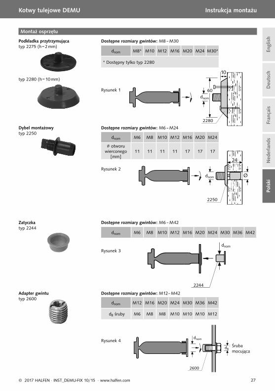
dnom M6 M8 M10 M12 M16 M20 M24
∅ otworu wierconego
[mm]11 11 11 11 17 17 17
dnom M8* M10 M12 M16 M20 M24 M30*
* Dostępny tylko typ 2280
dnom M6 M8 M10 M12 M16 M20 M24 M30 M36 M42
dnom M12 M16 M20 M24 M30 M36 M42
dB śruby M6 M8 M8 M10 M10 M10 M12
2280
dnom
2244
dnomdnom
2244
2250
dnom
2600
dnom
dBBefestigungs-
Schraube
Adapter gwintu typ 2600
Dostępne rozmiary gwintów: M12– M42
Dostępne rozmiary gwintów: M6 – M42Zatyczka typ 2244
Montaż osprzętu
Podkładka przytrzymująca typ 2275 (h = 2 mm)
Dostępne rozmiary gwintów: M8 – M30
Dostępne rozmiary gwintów: M6 – M24Dybel montażowy typ 2250
Rysunek 1
Rysunek 2
Rysunek 3
Śruba mocująca
Rysunek 4
typ 2280 (h = 10 mm)

28 © 2017 HALFEN · INST_DEMU-FIX 10/15 · www.halfen.com
Deu
tsch
Engl
ish
Fran
çais
Ned
erla
nds
Pols
kiKotwy tulejowe DEMU Instrukcja montażu
M
M
Mocowanie do szalunku Przygotowanie do montażu Śrubę wkręcić i dociągnąć
moment dokręcenia Tinst → patrz tabela na str. 30 należy uwzględniać zginanie śruby na skutek cofniętego położenia kotwy tulejowej (śruby nie są objęte dostawą)
Przypadek Apodkładka przytrzymująca z tworzywa sztucznego
Podkładki
Podkładka
Podkładka typ 2275 lub 2280
Przybić podkładkę: patrz str. 27, rys. 1
Przypadek Bmontaż przy użyciu dybla do zerwania
Dybel do zerwania typ 2250
Otwór w szalunku: patrz str. 27, rys. 2
Przypadek Ckotwy tulejowe ze zintegrowanym kołnierzem
Osadzić zatyczkę w tulei: patrz str. 27, rys. 3
Zatyczka typ 2244
Montaż (ilustracja: T-FIXX; mocowanie innych typów tulei analogicznie)
Usunąć szalunek,usunąć zatyczkę
Usunąć szalunek,wykręcić podkładkę
Usunąć szalunek,wykręcić część gwintowaną
29© 2017 HALFEN · INST_DEMU-FIX 10/15 · www.halfen.com
Deu
tsch
Engl
ish
Fran
çais
Ned
erla
nds
Pols
ki
Kotwy tulejowe DEMU Instrukcja montażu
a
b
cdnom dB
1.
M
dnom
Mocowanie do szalunku Przygotowanie do montażu Śrubę wkręcić i dociągnąć
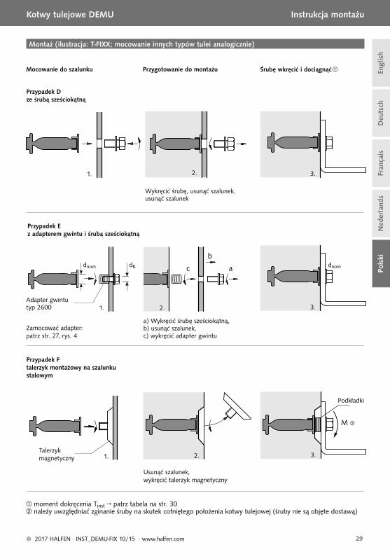
Przypadek Dze śrubą sześciokątną
moment dokręcenia Tinst → patrz tabela na str. 30 należy uwzględniać zginanie śruby na skutek cofniętego położenia kotwy tulejowej (śruby nie są objęte dostawą)
Przypadek Ez adapterem gwintu i śrubą sześciokątną
Przypadek Ftalerzyk montażowy na szalunku stalowym
Talerzyk magnetyczny
Podkładki
Montaż (ilustracja: T-FIXX; mocowanie innych typów tulei analogicznie)
Usunąć szalunek,wykręcić talerzyk magnetyczny
Wykręcić śrubę, usunąć szalunek,usunąć szalunek
Zamocować adapter: patrz str. 27, rys. 4
a) Wykręcić śrubę sześciokątną, b) usunąć szalunek, c) wykręcić adapter gwintu
Adapter gwintu typ 2600

30 © 2017 HALFEN · INST_DEMU-FIX 10/15 · www.halfen.com
Deu
tsch
Engl
ish
Fran
çais
Ned
erla
nds
Pols
kiKotwy tulejowe DEMU Instrukcja montażu
Moment wkręcenia Tinst [Nm]*
Rozmiar gwintu T-FIXX® Kotwa trzpieniowa/prętowa Kotwa tulejowaM10 ≤ 8 - ≤ 4M12 ≤ 10 ≤ 10 ≤ 8M16 ≤ 30 ≤ 30 ≤ 17M20 ≤ 60 ≤ 50 ≤ 25M24 - ≤ 90 ≤ 53M30 - ≤ 180 ≤ 96M36 - ≤ 250 -M42 - ≤ 300 -
* Momenty obowiązują tylko dla śrub w stanie nie nasmarowanym.
Minimalne długości wkręcenia s [mm]Rozmiar gwintu T-FIXX® Kotwa trzpieniowa
1988Kotwy trzpieniowe 1985/1980-P / kotwy prętowe /
kotwy tulejowe ,M6 - - 7,2M8 - - 9,6M10 17,0 - 12,0 / 15,0M12 19,0 16,4 14,4 / 18,0M16 26,0 21,2 19,2 / 24,0M20 32,0 26,0 24,0 / 30,0M24 - 30,8 28,8 / 36,0M30 - 38,0 36,0M36 - 45,2 43,2M42 - 52,4 50,4
s = 1,2 × dnom większe wartości (s = 1,5 × dnom) obowiązują dla kotew tulejowych ze zintegrowanym kołnierzem
→ typy 1985 (GV), 1036-G (GV, A4) i 1130 (GV).
Określenie wymaganej długości śrub
Ogólnie
Element budowlany mocowany jest przy pomocy śruby z gwintem metry-cznym, podkładki i nakrętki kontrującej w zabetonowanej kotwie tulejowej. Wymienione komponenty do mocowania nie są zawarte w do-stawie i muszą być oddzielnie zama-wiane. Należy stosować śruby według wytycznych projektanta.
Długość wkręcenia
Przy stosowaniu kotew tulejowych należy zwracać uwagę na minimalne i maksymalne długości wkręcenia śrub. Minimalne długości wkręcenia zesta-wiono w tabeli poniżej. Określenie wymaganej długości śrub opisane jest w następnym punkcie.
Określenie wymaganej długości śruby (Ls)
Długość śruby (Ls)Ls,min = s + k (minimalna długość śruby)Ls,max = a + k (maksymalna długość śruby)
k = grubość mocowania(grubość elementu budowlanego i podkładki)
s = minimalna długość wkręcenia (→ patrz tabela poniżej)a = maksymalna długość wkręcenia (→ patrz tabele na str. 31)
Ls,maxLs,min
a
31© 2017 HALFEN · INST_DEMU-FIX 10/15 · www.halfen.com
Deu
tsch
Engl
ish
Fran
çais
Ned
erla
nds
Pols
ki
Kotwy tulejowe DEMU Instrukcja montażu
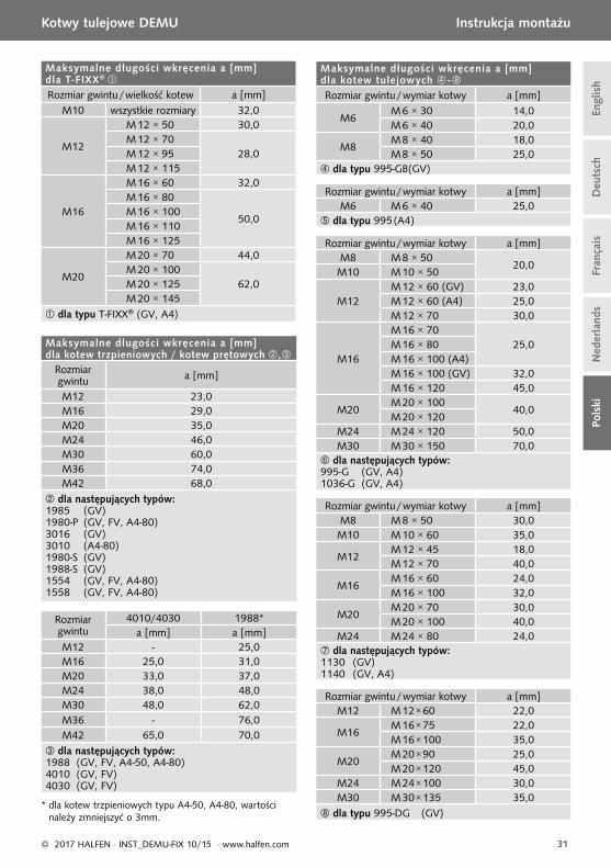
Maksymalne długości wkręcenia a [mm] dla kotew tulejowych -Rozmiar gwintu / wymiar kotwy a [mm]
M6M 6 × 30 14,0M 6 × 40 20,0
M8M 8 × 40 18,0M 8 × 50 25,0
dla typu 995-GB (GV)
Rozmiar gwintu / wymiar kotwy a [mm]M6 M 6 × 40 25,0
dla typu 995 (A4)
Rozmiar gwintu / wymiar kotwy a [mm]M8 M 8 × 50
20,0M10 M 10 × 50
M12M 12 × 60 (GV) 23,0M 12 × 60 (A4) 25,0M 12 × 70 30,0
M16
M 16 × 7025,0M 16 × 80
M 16 × 100 (A4)M 16 × 100 (GV) 32,0M 16 × 120 45,0
M20M 20 × 100
40,0M 20 × 120
M24 M 24 × 120 50,0M30 M 30 × 150 70,0
dla następujących typów:995-G (GV, A4)1036-G (GV, A4)
Rozmiar gwintu / wymiar kotwy a [mm]M8 M 8 × 50 30,0M10 M 10 × 60 35,0
M12M 12 × 45 18,0M 12 × 70 40,0
M16M 16 × 60 24,0M 16 × 100 32,0
M20M 20 × 70 30,0M 20 × 100 40,0
M24 M 24 × 80 24,0 dla następujących typów:1130 (GV)1140 (GV, A4)
Rozmiar gwintu / wymiar kotwy a [mm]M12 M 12 × 60 22,0
M16M 16 × 75 22,0M 16 × 100 35,0
M20M 20 × 90 25,0M 20 × 120 45,0
M24 M 24 × 100 30,0M30 M 30 × 135 35,0
dla typu 995-DG (GV)
Maksymalne długości wkręcenia a [mm] dla T-FIXX®
Rozmiar gwintu / wielkość kotew a [mm]M10 wszystkie rozmiary 32,0
M12
M 12 × 50 30,0M 12 × 70
28,0M 12 × 95M 12 × 115
M16
M 16 × 60 32,0M 16 × 80
50,0M 16 × 100M 16 × 110M 16 × 125
M20
M 20 × 70 44,0M 20 × 100
62,0M 20 × 125M 20 × 145
dla typu T-FIXX® (GV, A4)
Maksymalne długości wkręcenia a [mm] dla kotew trzpieniowych / kotew prętowych ,
Rozmiar gwintu a [mm]
M12 23,0M16 29,0M20 35,0M24 46,0M30 60,0M36 74,0M42 68,0
dla następujących typów:1985 (GV)1980-P (GV, FV, A4-80)3016 (GV)3010 (A4-80)1980-S (GV)1988-S (GV)1554 (GV, FV, A4-80)1558 (GV, FV, A4-80)
Rozmiar gwintu
4010/4030 1988*a [mm] a [mm]
M12 - 25,0M16 25,0 31,0M20 33,0 37,0M24 38,0 48,0M30 48,0 62,0M36 - 76,0M42 65,0 70,0
dla następujących typów:1988 (GV, FV, A4-50, A4-80)4010 (GV, FV)4030 (GV, FV)
* dla kotew trzpieniowych typu A4-50, A4-80, wartości należy zmniejszyć o 3mm.

© 2
017
HA
LFEN
Gm
bH, G
erm
any
appl
ies
also
to
copy
ing
in e
xtra
cts.
CONTACT HALFEN WORLDWIDE
HALFEN is represented by subsidiaries in the following countries, please contact us:
NOTES REGARDING THIS DOCUMENTTechnical and design changes reserved. The information in this publication is based on state-of-the-art technology at the time of publication. We reserve the right to make technical and design changes at any time. HALFEN GmbH shall not accept liability for the accuracy of the information in this publication or for any printing errors.
The HALFEN GmbH subsidiaries in Germany, France, the Netherlands, Austria, Poland, Switzerland and the Czech Republic are Quality Management certifi ed according to ISO 9001:2015, Certifi cate no. 202384-2016-AQ-GER-DAkkS.
HALFEN is represented with sales offi ces and distributors worldwide.
Please contact us: www.halfen.com
www.dnvgl.com
Austria HALFEN Gesellschaft m.b.H.Leonard-Bernstein-Str. 101220 Wien
Phone: +43 - 1 - 259 6770 E-Mail: offi [email protected]: www.halfen.at
Fax: +43 - 1 - 259 - 6770 99
Belgium /Luxembourg
HALFEN N.V.Borkelstraat 1312900 Schoten
Phone: +32 - 3 - 658 07 20E-Mail: [email protected]: www.halfen.be
Fax: +32 - 3 - 658 15 33
China HALFEN Construction Accessories Distribution Co.Ltd.Room 601 Tower D, Vantone CentreNo.A6 Chao Yang Men Wai StreetChaoyang District Beijing · P.R. China 100020
Phone: +86 - 10 5907 3200E-Mail: [email protected]: www.halfen.cn
Fax: +86 - 10 5907 3218
Czech Republic HALFEN s.r.o.Business Center ŠafránkovaŠafránkova 1238/1155 00 Praha 5
Phone: +420 - 311 - 690 060E-Mail: [email protected]: www.halfen-deha.cz
Fax: +420 - 235 - 314308
France HALFEN S.A.S.18, rue Goubet75019 Paris
Phone: +33 - 1 - 445231 00E-Mail: [email protected]: www.halfen.fr
Fax: +33 - 1 - 445231 52
Germany HALFEN Vertriebsgesellschaft mbHLiebigstr. 14 40764 Langenfeld
Phone: +49 - 2173 - 970 0E-Mail: [email protected]: www.halfen.de
Fax: +49 - 2173-970 225
Italy HALFEN S.r.l. Soc. UnipersonaleVia F.lli Bronzetti N° 2824124 Bergamo
Phone: +39 - 035 - 0760711E-Mail: [email protected]: www.halfen.it
Fax: +39 - 035 - 0760799
Netherlands HALFEN b.v.Oostermaat 37623 CS Borne
Phone: +31 - 74-267 14 49E-Mail: [email protected]: www.halfen.nl
Fax: +31 - 74-2 67 26 59
Norway HALFEN ASPostboks 20804095 Stavanger
Phone: +47 - 51 82 34 00E-Mail: [email protected]: www.halfen.no
Fax: +47 - 51 82 34 01
Poland HALFEN Sp. z o.o.Ul. Obornicka 28760-691 Poznan
Phone: +48 - 61 - 622 14 14E-Mail: [email protected]: www.halfen.pl
Fax: +48 - 61 - 622 14 15
Spain HALFEN SpainPLAKABETON S.L.Polígono Industrial Santa Ana c/ Ignacio Zuloaga 2028522 Rivas-Vaciamadrid
Phone: +34 916 669 181E-Mail: [email protected]: www.halfen.es
Fax: +34 916 669 661
Sweden Halfen ABVädursgatan 5412 50 Göteborg
Phone: +46 - 31 - 98 58 00E-Mail: [email protected]: www.halfen.se
Fax: +46 - 31 - 98 58 01
Switzerland HALFEN Swiss AGHertistrasse 25 8304 Wallisellen
Phone: +41 - 44 - 849 78 78E-Mail: [email protected]: www.halfen.ch
Fax: +41 - 44 - 849 78 79
United Kingdom /Ireland
HALFEN Ltd.A1/A2 Portland CloseHoughton Regis LU5 5AW
Phone: +44 - 1582 - 47 03 00E-Mail: [email protected]: www.halfen.co.uk
Fax: +44 - 1582 - 47 03 04
United States of America
HALFEN USA Inc. PO Box 18687 San Antonio TX 78218
Phone: +1 800.423.91 40E-Mail: [email protected]: www.halfenusa.com
Fax: +1 877.683.4910
For countries not listed HALFEN International
HALFEN International GmbHLiebigstr. 14 40764 Langenfeld / Germany
Phone: +49 - 2173 - 970 - 0 E-Mail: [email protected]: www.halfen.com
Fax: +49 - 2173 - 970 - 849
U -
243
- 07/
17