installation and maintenance for series 47 k-flo … · installation and maintenance for series 47...
TRANSCRIPT

I N S T A L L A T I O N A N DM A I N T E N A N C E F O RS E R I E S 4 7 K - F L O
B U T T E R F L Y V A L V E S
PO Box 411Berwick PA 18603
800-247-VALVwww.crispinvalve.com

Product Introduction -- K-FLO Series 47: 24”-168”
Instructions These instructions are intended for personnel who are responsible for the installation,operation and maintenance of your K-FLO AWWA butterfly valve.
Safety All safety messages herein are flagged with the word Caution, Warning or Danger.Messages These messages must be followed to avoid equipment damage, personal injury or death.
Safety label(s) on the product indicate hazards that can cause equipment damage, personal injury or death. If a safety label becomes difficult to see, or if a label has beenremoved, please contact Crispin Valve for replacement.
Personnel involved in the installation or maintenance of valves should be constantly alertto the potential emission of process material and take appropriate safety precautions.Always wear suitable protection when dealing with hazardous process materials. Handlevalves which have been removed from service with the assumption that process materialcould be present within the valve.
Inspection Your AWWA butterfly valve has been packed to provide protection during shipment.Inspect the unit for damage upon arrival and file a carrier claim if damage is apparent.
Parts Order parts from your local sales representative, or directly from Crispin Valve.
Crispin Valve Crispin service personnel are available to install, maintain and repair all Crispin ValvesService and products. Crispin also offers customized training programs and consultation services.
For more information, contact your local Crispin/K-FLO Valve sales representative orvisit our website at www.crispinvalve.com
Table of Description ..............................................................................................................AContents Flange Requirements ..............................................................................................A
Installation Instructions...........................................................................................CParts Identification..................................................................................................BInstallation Adjustments .........................................................................................CMaintenance and Repair .........................................................................................DLubrication..............................................................................................................DSeat Replacement ...................................................................................................DSeat Adjustment......................................................................................................DShaft Bearing Replacement.....................................................................................EDisc/Stem Replacement ..........................................................................................FRecommended Storage Procedures.........................................................................FTroubleshooting ......................................................................................................G
Description K-FLO AWWA Butterfly Valves are heavy-duty, rubber seated butterfly valves in fullcompliance with AWWA C-504 for use in municipal water treatment, power generation,and industrial applications.
Maintenance This valve is assembled using standard SAE fasteners. To service this valve, you shouldhave a full set of combination wrenches, flat tipped screwdrivers, allen wrenches, a torquewrench, sockets, chisels, a hooked tool for removing the packing and a dead blow hammer.Periodic lubrication is not necessary with the basic valve. K-FLO valves utilize bearings thatare of the self-lubricating type which provide strength and low friction for easy operationand lifetime service. No special periodic maintenance is necessary.See the actuator andaccessory instructions for any lubrication requirements these assemblies may have.
Flange The K-FLO Butterfly Valves are designed for installation between ANSI B16.1 Class Requirements 125# flat faced flanges. Mechanical joint valves are designed for use with AWWA C111
end connections. MJ accessories for the pipe used must be supplied by the installing contractor. Class 250 valves can be ordered with either ANSI B16.1 250# drilling, ANSIB16.1 125# drilling or AWWA C111 MJ ends.
A

K-FLO Series 47--Installation Instructions
B
K-FLO Series 47--Installation Instructions
C
Installation Instructions
Failure to lift the valve properly may cause damage.
Lift the valve with non-metallic slings fastened around the valvemounting plate, or attach them to bolts or rods run through theflange bolt holes.
Do not fasten lifting devices to the actuator or disc, or through theseat opening in the body.
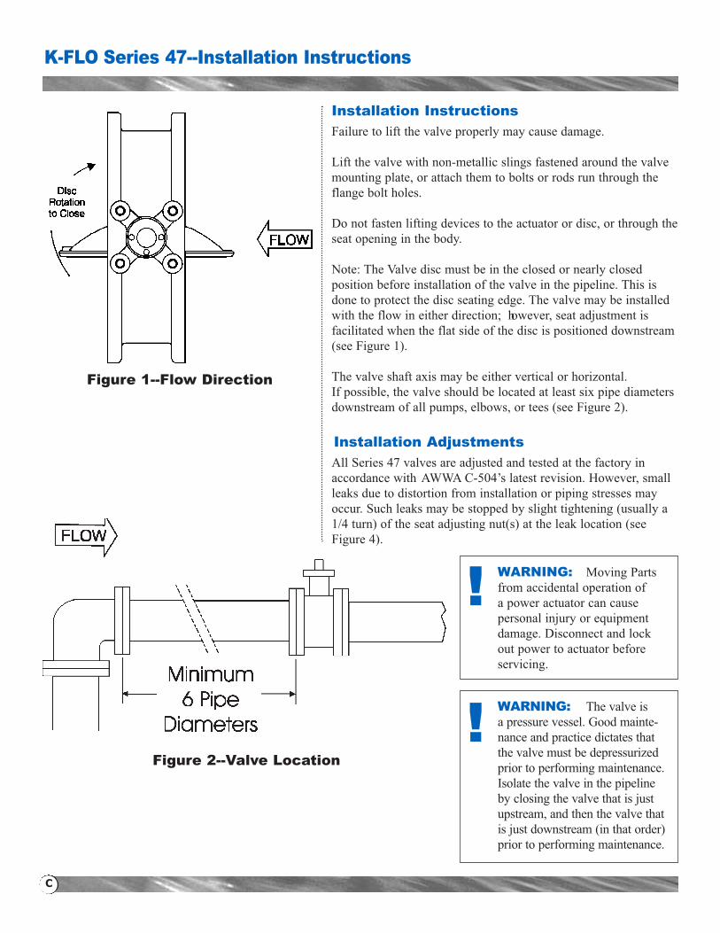
Note: The Valve disc must be in the closed or nearly closed position before installation of the valve in the pipeline. This isdone to protect the disc seating edge. The valve may be installedwith the flow in either direction; however, seat adjustment isfacilitated when the flat side of the disc is positioned downstream(see Figure 1).
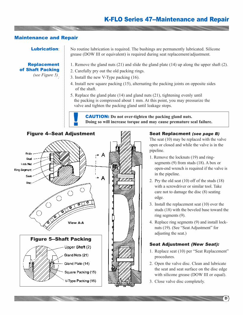
The valve shaft axis may be either vertical or horizontal.If possible, the valve should be located at least six pipe diametersdownstream of all pumps, elbows, or tees (see Figure 2).
Installation Adjustments
All Series 47 valves are adjusted and tested at the factory inaccordance with AWWA C-504’s latest revision. However, smallleaks due to distortion from installation or piping stresses mayoccur. Such leaks may be stopped by slight tightening (usually a1/4 turn) of the seat adjusting nut(s) at the leak location (seeFigure 4).
WARNING: Moving Partsfrom accidental operation of a power actuator can cause personal injury or equipmentdamage. Disconnect and lockout power to actuator beforeservicing.
WARNING: The valve is a pressure vessel. Good mainte-nance and practice dictates thatthe valve must be depressurizedprior to performing maintenance.Isolate the valve in the pipelineby closing the valve that is justupstream, and then the valve thatis just downstream (in that order)prior to performing maintenance.
!
!
Figure 1--Flow Direction
Figure 2--Valve Location
K-FLO Series 47--Maintenance and Repair
D
Maintenance and Repair
Lubrication: No routine lubrication is required. The bushings are permanently lubricated. Silicone grease (DOW III or equivalent) is required during seat replacement/adjustment.
Replacement 1. Remove the gland nuts (21) and slide the gland plate (14) up along the upper shaft (2).of Shaft Packing 2. Carefully pry out the old packing rings.
(see Figure 5): 3. Install the new V-Type packing (16).4. Install new square packing (15), alternating the packing joints on opposite sides of the shaft.
5. Replace the gland plate (14) and gland nuts (21), tightening evenly until the packing is compressed about 1 mm. At this point, you may pressurize the valve and tighten the packing gland until leakage stops.
!
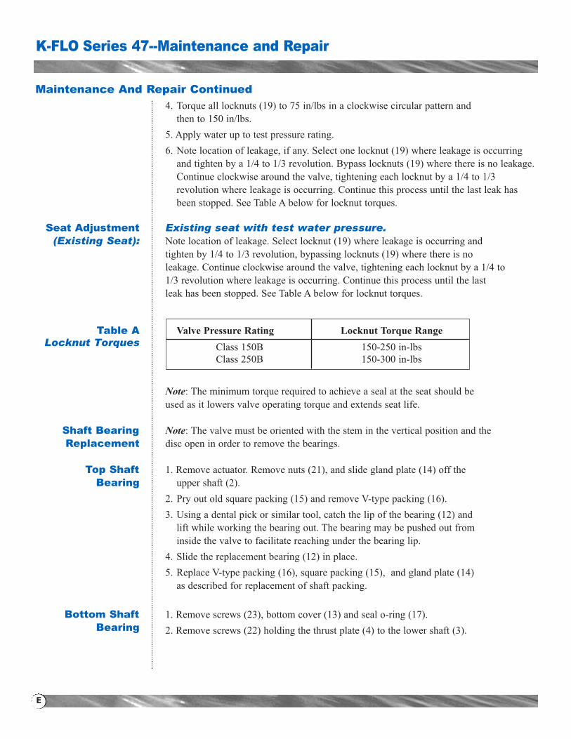
Figure 5--Shaft Packing
Figure 4--Seat Adjustment
View A-A
Seat Replacment (see page B)The seat (10) may be replaced with the valveopen or closed and while the valve is in thepipeline.1. Remove the locknuts (19) and ring-segments (9) from studs (18). A box oropen-end wrench is required if the valve isin the pipeline.
2. Pry the old seat (10) off of the studs (18)with a screwdriver or similar tool. Takecare not to damage the disc (8) seatingedge.
3. Install the replacement seat (10) over thestuds (18) with the beveled base toward thering segments (9).
4. Replace ring segments (9) and install lock-nuts (19). (See “Seat Adjustment” foradjusting the seat.)
Seat Adjustment (New Seat):
1. Replace seat (10) per “Seat Replacement”procedures.
2. Open the valve disc. Clean and lubricatethe seat and seat surface on the disc edgewith silicone grease (DOW III or equal).
3. Close valve disc completely.
CAUTION: Do not over-tighten the packing gland nuts. Doing so will increase torque and may cause premature seal failure.
Maintenance And Repair Continued
4. Torque all locknuts (19) to 75 in/lbs in a clockwise circular pattern and then to 150 in/lbs.
5. Apply water up to test pressure rating.6. Note location of leakage, if any. Select one locknut (19) where leakage is occurring and tighten by a 1/4 to 1/3 revolution. Bypass locknuts (19) where there is no leakage. Continue clockwise around the valve, tightening each locknut by a 1/4 to 1/3 revolution where leakage is occurring. Continue this process until the last leak has been stopped. See Table A below for locknut torques.
Seat Adjustment Existing seat with test water pressure.(Existing Seat): Note location of leakage. Select locknut (19) where leakage is occurring and
tighten by 1/4 to 1/3 revolution, bypassing locknuts (19) where there is no leakage. Continue clockwise around the valve, tightening each locknut by a 1/4 to 1/3 revolution where leakage is occurring. Continue this process until the last leak has been stopped. See Table A below for locknut torques.
Table A Valve Pressure Rating Locknut Torque RangeLocknut Torques Class 150B 150-250 in-lbs
Class 250B 150-300 in-lbs
Note: The minimum torque required to achieve a seal at the seat should be used as it lowers valve operating torque and extends seat life.
Shaft Bearing Note: The valve must be oriented with the stem in the vertical position and theReplacement disc open in order to remove the bearings.
Top Shaft 1. Remove actuator. Remove nuts (21), and slide gland plate (14) off theBearing upper shaft (2).
2. Pry out old square packing (15) and remove V-type packing (16).3. Using a dental pick or similar tool, catch the lip of the bearing (12) and lift while working the bearing out. The bearing may be pushed out frominside the valve to facilitate reaching under the bearing lip.
4. Slide the replacement bearing (12) in place.5. Replace V-type packing (16), square packing (15), and gland plate (14) as described for replacement of shaft packing.
Bottom Shaft 1. Remove screws (23), bottom cover (13) and seal o-ring (17).Bearing 2. Remove screws (22) holding the thrust plate (4) to the lower shaft (3).
K-FLO Series 47--Maintenance and Repair
E

K-FLO Series 47--Maintenance and Repair
F
Maintenance And Repair Continued
3. Using a dental pick or similar tool, catch the lip of the bearing (12) and lift while working the bearing cut The bearing may be pushed out from inside the valve to facilitate reaching under the bearing lip.
4. Slide the replacement bearing (12) in place.5. Fasten thrust plate (4) to the lower shaft (3) with screws (22).6. Replace seal o-ring (17) with a new one and secure the bottom cover plate (13) with screws (23).
Disc/Shaft The disc/shaft assembly is drilled and pinned at the factory as a matched set.Replacement If replacement of either the disc or stem should be required, Crispin Valve
recommends that the valve be returned to the factory for such service.
Recommended Storage Procedures
Long-Term 1. All resilient seated valves shall be stored in the open (unseated) position.Storage 2. All valves with adjustable packing glands should have the packing gland
loosened prior to storage.3. Valves shall be separately packaged in a sealed polyethylene plastic enclosure with a minimum of one package of dessicant inside, dependent upon valve size.
4. Prepared valves shall be warehoused in a clean, dry, indoor facility on concreteor raised racks, with temperature ranging from 35°F to 95°F (2°C to 35°C).
5. Valves shall not be near electric motors or other equipment which may emitOzone. This can cause deterioration of elastomer components in the valve and actuator.
6. The valves shall be inspected periodically. Replace the dessicant if required,and repair any damage to the polyethylene plastic enclosures.
7. Valves with cylinder operators and controls that are stored for extended periods may be subject to cylinder blow-by caused by permanent distortion of any of the seals. Valves should be operated prior to installation and damaged sealsreplaced.
8. Valves with electric motor operators shall be stored in accordance with theindividual motor manufacture’s recommended long-term storage procedures, in addition to Steps 1, 2 and 3 above.
9. All electrical components, if applicable, should be inspected and allelectrical contacts cleaned before operation.
10. Valves shall be enclosed in fully sheathed wooden crates or boxes.
Short-Term 1. Valves should be protected from the weather. Avoid exposure to Storage excessive moisture or dirt. Store at temperatures ranging from 35°F
to 95°F (2°C to 35°C).

K-FLO Series 47--Troubleshooting
G
Valve opens only a few degrees andstops (it will not open to the full angledesired)
Improper Installation. The valve isimproperly aligned.
Mating pipe internal diameter or otherobstuction is interfering with disc.
Actuator not properly installed
Loosen the flange bolts. Realign thevalve with flanges, and retighten theflange bolts to correct torque per ANSIrequirements.
Pipe does not meet standards and spacers may be required. Any pipelineor disc obstruction must be removed.
Refer to actuator adjustment manual.
Leakage past the flange face
Flange bolts are not evenly torqued.
Improper flanges
Improper flange gaskets
Loosen the flange bolts and tighten theflange bolts to correct torque per ANSIrequirements.
Refer to “Flange Requirements” on page A.
Full face flange gaskets required.
Leakage in the closed position (leakage in the pipeline)
The disc is not closing fully: Actuator is not properly adjusted.
Damaged or improperly aligned valveseat
Line pressure exceeds valve’s workingpressure
Damaged valve disc
Refer to “Actuator Adjustment” procedures.
Follow “Seat Adjustment” procedures onpage 5, or replace seat if damaged.
Reduce line pressure to valve workingpressure.
Return valve to factory for disc/stem replacement.
Leakage at the valve stem Packing failure
1. Fully open and close the valve 3 times.
2. Refer to “Replacement of Shaft Packing” on page D.
Water Hammer The valve is closing too quickly. Turn actuator slower.
Excessively high torque to operate valve
Obstruction in the pipeline
Valve shaft or disc bent
Scale buildup on shaft or seat
Remove valve from pipeline and removeobstruction.
Return valve to factory for disc/shaftreplacement (check for water hammeror freezing of line material).
Open and close the valve several times.Operate the valve at least once a month.Check the valve seat for deterioration.
SYMPTOMS POSSIBLE CAUSE SUGGESTED REMEDY