installation and maintenance instructions for legend® lightbar · installation and maintenance...
TRANSCRIPT

2562246AREV. A 907Printed in U.S.A.
INSTALLATION AND MAINTENANCE INSTRUCTIONS FOR
LEGEND® LIGHTBAR
SAFETY MESSAGE TO INSTALLERS OF FEDERAL SIGNAL LIGHT SYSTEMS
People’s lives depend on your safe installation of our products. It is important to read, understand and follow all instructions shipped with the products. In addition, listed below are some other important safety instructions and precautions you should follow:
• Toproperlyinstallalightassembly:youmusthaveagoodunderstandingofautomotiveelectricalproceduresandsystems,alongwithproficiencyintheinstallationanduseofsafetywarningequipment.
• Wheninstallingequipmentorwiringinsideairbagequippedvehicles,theinstallerMUSTen-surethattheequipmentorwiringisinstalledONLYinareasrecommendedbythevehiclemanufacturer.Failuretoobservethiswarn-ingwillreducetheeffectivenessoftheairbag,damagetheairbag,orpotentiallydamageordislodgetheequipment,causingseriousinjuryordeathtoyouorothers.
• Whendrillingintoavehiclestructure,besurethatbothsidesofthesurfaceareclearofany-thingthatcouldbedamaged.
• Alightsystemisahighcurrentdevice.Inorderforittofunctionproperly,aseparategroundconnectionmustbemade.Ifpractical,itshouldbeconnectedtothenegativebatteryterminal.Ataminimum,itmaybeattachedtoasolidmetalbodyorchassispartthatwillprovideaneffectivegroundpathaslongasthelightsystemistobeused.
• LocatelightsystemcontrolssotheVEHICLEandCONTROLScanbeoperatedsafelyunderalldrivingconditions.
• ThisproductcontainshighintensityLEDde-vices.Topreventeyedamage,DONOTstareintothelightbeamatcloserange.
• Youshouldfrequentlyinspectthelightsystemtoensurethatitisoperatingproperlyandthatitissecurelyattachedtothevehicle.
• Filetheseinstructionsinasafeplaceandrefertothemwhenmaintainingand/orreinstallingtheproduct.
Failure to follow all safety precautions and instructions may result in property damage, serious injury, or death to you or others.
I. GENERAL.
TheLegendisasinglelevelLEDlightbar,employingROC“BigBoard”technologyandSolarisS2reflectors.Thebaroperatesatanominalinputof13.6VDC(11VDCminimum).ThebasiclightfunctionsoftheunitarecontrolledviatheCAT5serialcommunicationcable.ThecableconnectstoeitheracompatibleFederalSignalSerialcontrolhead,or,aFederalSignalSerialInterfaceModule,8583446.AninternalPCBassembly,withinthelightbar,decodesthecontroldataandperformstherequestedfunction.Withtheinterfacebox,thebarmaybeactivatedbyFederalSignallightbarcontrollers,Signalmastercontrollers,and/orindividuallowcurrentswitches.Thebackboneisanaluminumextrusionandthebasesandtopsaremoldedpolycarbonate.Thebarshavetwenty-one-footpowerandgroundcables,andatwenty-five-footserialcable.MountinghardwareisaConfiguredoption.Refertomountinginstructionssuppliedwithmountinghardware.Thebarshaveanoperatingtemperaturerangeof-30°Cto+65°C.
II. UNPACKING.
AfterunpackingtheLegendlightassembly,inspectitfordamagethatmayhaveoccurredintransit.Iftheunithasbeendamaged,donotattempttoinstalloroperateit.Fileaclaimimmediatelywiththecarrier,statingtheextentofdamage.Carefullycheckallenvelopes,shippinglabels,andtagsbeforeremovingordestroyingthem.
III. INSTALLATION.
Improper warning system and/or twoway radio system operation may result if a twoway Radio antenna installed on, or within 18inches of, the lightbar. Before permanent installation of the lightbar or a twoway radio antenna, test the warning system and twoway radio system. DO NOT install a twoway radio antenna on the lightbar.
Some installations may require relocation of the twoway radio antenna to a trunk or fender location.
Warning system failure may result if additional holes are drilled in the lightbar, or if auxiliary devices are installed on the lightbar. DO NOT drill additional holes in the lightbar, or install auxiliary devices on the lightbar.

NOTE
IftheinternalSignalMasteroptionwillbeused,thelightbarshouldbeconfiguredpriortomechani-calmounting.RefertoparagraphG,SignalMasterControls.
A. General.
Beforeproceeding,ensurethatthelightbarhasbeeninstalledonthevehicleroofinaccordancewiththeinstructionspackedwiththemountingkit.
Thelightbariscompletelywiredatthefactoryanddoesnotrequireanyadditionalinternalwiring;two10AWGpowerconductors(redandblack)andtheCAT5communicationcableexitthelightbar.AlltheconductorsnecessaryforcontrolofanyandallbasicandoptionalfunctionsarecontainedintheCAT5cable.ThebasiclightfunctionsoftheunitarecommunicatedviatheCAT5cable.ThecableconnectstoeitheracompatibleFederalSignalSerialcontrolhead,or,aFederalSignalSerialInterfaceModule.
Light system controls must be located so that the VEHICLE and CONTROLS can be operated safely under all driving conditions.
B. Seefigure1.Ensurethatthelinesareadequatelyfusedasshown.Fromthelightbar,routetheCAT5controlcableintothevehicle’scabortrunkneartheeventuallocationofthecompatibleFederalSignalSerialcontrolheadorFSC#8583446InterfaceModule.AninputcableisalsoprovidedwiththeFSC#8583446SerialInterfaceModule.
Reversepolaritymaydamagethelightbarandpreventoperation.Ensurethatcorrectpolarityisobserved.Unitmustbefusedatthesource.
C. Routeandconnecttheseparate10gaugeblackleadtothevehiclebatteryground(-)terminal.
-2-
D. Routeandconnectthe10gaugeredlead,throughthesupplied40Afuse,fusedatthesource,totheBAT+terminal.
E. SignalMaster Option.
TheSignalMasterfunctioniscompletelyconfiguredatthefactoryanddoesnotrequireanyadditionalwiringinsidethelightbar.AllconductorsnecessaryforcontroloftheSignalMasterisviathecompatibleSerialcommunicationcontrolheadortheFSC#8583446SerialInterfaceModule.Forwiringandoperationinstructions,refertotheinstructionsheetpackedwiththeapplicablecontrolheadortheFSCSerialInterfaceModule’sInstructionsheet(partnumber2562248).Thelightbar’sSignalMasteroperationisfactoryconfiguredforusewithaFederalSignalSignalMastercontrollerorSS2000SMseriessiren(EXTERNALconfiguration).
F. Light Bar Controls.
TheLegendS2functionsarecommunicatedviatheCAT5serialcable.BoththeFederalSignalSerialControlHeadandtheSerialInterfaceModulearecapableofprovidingthefollowingcontrolstothelightbar.Forprogrammingoptions,refertotheInstallationManualshippedwiththeInterfaceModuleortheFederalSignalSerialControlHead. 1. MODE1- 2. MODE2–overridesMODE1; 3. MODE3–OverridesMODES1&2; 4. STEADYBURNRED 5. FRONTCUTOFF 6. REARCUTOFF 7. INTERSECTION 8. FLASHHALOGEN 9. LEFTALLEY 10. RIGHTALLEY 11. TAKEDOWN 12. LOWPOWER 13. LIGHTBARTESTPATTERN
G. SignalMaster Controls (INTERNAL configuration).
ToconfigurethelightbarforINTERNALSignalMasteroperation,seefigure2andrefertoparagraphV.6.a,PCBControllerreplacement.Movethejumperfromthe“E”positiontothe“I”position. ThefollowingpatternsareaccessiblewithINTERNALconfiguration:
1. LEFT 2. CENTER 3. RIGHT 4. WARN1 5. WARN2 6. WARN3 7. WARN4 8. FAST
H. Typical Installations.
Fortypicalinstallationswithcommoncontrolsystems,seeinstallationwiringdiagrams1,2,3,and4attheendofthisdocument.
Figure 1.
290A5656B
LIGHTBAR
FSC SERIAL INTERFACE MODULEPART #8583446 REFERENCEINSTRUCTION SHEET 2562248
SERIAL, CAT5., CONTROL CABLE
- +
BLACK 10AWG
RED 10AWG
FUSE 40AMP
BLA
CK
WH
ITE
BLA
CK
/ W
HIT
E
16AWG
IGNITION
1A
BATTERY

-3-
290A5657
EXTERNALSIGNALMASTER CONFIGURATOR
INTERNALSIGNALMASTER CONFIGURATOR
15A FUSES
Figure 2.
IV. OPERATION.
This product contains high output LED devices. To prevent permanent eye damage, do not stare into the light beam at close range.
NOTE
Applying12VDCtotheappropriatecontrollineandignitionwireontheSerialInterfaceModulecanactivateallthelightbarfunctions.The10gaugeblackandredpowerleadsmustbecon-nectedtotheirrespectivebatteryterminalsforafunctioncheck.
Afterinstallation,checktheentiresystemtobesurethelightsareflashingproperlyandalllightsystemfunctionsareoperatingproperly.
SAFETY MESSAGE TO OPERATORS
People’s lives depend on your safe use of our products.
Listed below are some important safety instructions and precautions you should follow:
• Althoughyourwarningsystemisoperatingproperly,itmaynotbecompletelyeffective.Peoplemaynotseeorheedyourwarningsig-nal.Youmustrecognizethisfactandcontinuedrivingcautiously.
• Also,situationsmayoccurwhichobstructyourwarningsignalwhennaturalormanmadeob-jectsarebetweenyourvehicleandothers,suchas:raisingyourhoodortrunklid.Ifthesesitu-ationsoccur,beespeciallycareful.
• ThisproductcontainshighintensityLEDde-vices.Topreventpermanenteyedamage,DONOTstareintothelightbeamatcloserange.
• Atthestartofyourshift,youshouldensurethatthelightissecurelyattachedandoperat-ingproperly.
Failure to follow these safety precautions may result in property damage, serious injury, or death to you, to passengers, or to others.
RETAIN AND REFER TO THIS MESSAGE
V. MAINTENANCE.
Crazing (cracking) of lenses will cause reduced effectiveness of the light. Do not use cleaning agents (which will cause crazing) such as strong detergents, solvents, or petroleum products. If crazing of lenses does occur, reliability of light for emergency signaling purposes may be reduced until lenses are replaced.
Afterprolongedoperation,theunitgetshotandcancauseburns.Donottouchtheunitwhileorshortlyafterithasbeenoperating.Alwaysallowtheunittocoolbeforehandling.
A. General.
Ordinarycleaningoftheplasticlensescanbeaccomplishedbyusingmildsoapandasoftrag.Shouldfinescratchesorahazeappearonalens,theycanbestberemovedwithaspecialtyplasticcleaner/polishsuchasPlexus®andasoftcloth.Alternatively,non-abrasive,highquality,one-step,automotivepastecleaner/waxmaybeused.
B. Top Removal (see figure 3).
Donotovertightennuts.
RemovethePhillipsheadbarrelnutsthencarefullyremovethetoptoavoiddamagingthelipseal.Verifythatano-ringisundertheheadofeach
290A5658
Figure 3.
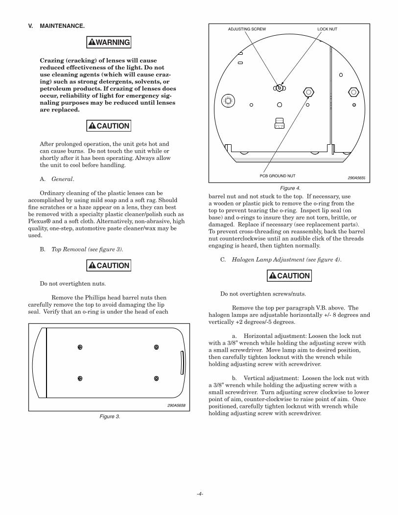
290A5659PCB GROUND NUT
ADJUSTING SCREW LOCK NUT
Figure 4.
barrelnutandnotstucktothetop.Ifnecessary,useawoodenorplasticpicktoremovetheo-ringfromthetoptopreventtearingtheo-ring.Inspectlipseal(onbase)ando-ringstoinsuretheyarenottorn,brittle,ordamaged.Replaceifnecessary(seereplacementparts).Topreventcross-threadingonreassembly,backthebarrelnutcounterclockwiseuntilanaudibleclickofthethreadsengagingisheard,thentightennormally.
C. Halogen Lamp Adjustment (see figure 4).
Donotovertightenscrews/nuts.
RemovethetopperparagraphV.B.above.Thehalogenlampsareadjustablehorizontally+/-8degreesandvertically+2degrees/-5degrees.
a. Horizontaladjustment:Loosenthelocknutwitha3/8”wrenchwhileholdingtheadjustingscrewwithasmallscrewdriver.Movelampaimtodesiredposition,thencarefullytightenlocknutwiththewrenchwhileholdingadjustingscrewwithscrewdriver.
b. Verticaladjustment:Loosenthelocknutwitha3/8”wrenchwhileholdingtheadjustingscrewwithasmallscrewdriver.Turnadjustingscrewclockwisetolowerpointofaim,counter-clockwisetoraisepointofaim.Oncepositioned,carefullytightenlocknutwithwrenchwhileholdingadjustingscrewwithscrewdriver.
-4-

D. Halogen Lamp Replacement.
A serious injury may result if the lamp is touched when hot. Always allow lamp to cool before removing. Halogen lamps are pressurized and if broken can result in flying glass. Always wear gloves and eye protection when handling lamps.
Servicelifeofthelampwillbeshortenediftheglassportionistouched.Iftheglasshasbeenhandled,cleancarefullywithagreasesolvent.
a. Takedownlamps:Seefigures4and5.RemovetopperparagraphV.B.RemovePCBgroundnut,theninvertPCBtoaccesslamp.Seethereplacementpartslistandreplacethedefectivelampwithanexactreplacementonly.Assembleinreverseorder.Donotovertightennuts.
b. Alleylamps:Seefigures4and6.RemovetopperparagraphV.B.RemovePCBgroundnut,theninvertPCBtoaccesslamp.Witha1/16”hexkey,removethelampretainingscrewsandclamps.Slidelampandsocketfromhousingjustfarenoughtograspsocket(itmaybenecessarytounplugconnectortogainadequateslackinleads).Holdingsocketfirmly,unpluglamp.Seethereplacementpartsandreplacethedefectivelampwithanexactreplacementonly.Assembleinreverseorder.Donotovertightenscrewsandnuts.
E. Cleaning Reflector Assemblies.
Useasofttissuetocleanreflectors.Avoidheavypressureandtheuseofcaustic,abrasive,orpetroleum-basecleaners,whichwillscratchordullthesurface.
F. PCB Controller Replacement (see figure 7) and Halogen/LED Head Fuse Access.
1. RemovethepassengersideenddomeperparagraphV.B.,removethePCBgroundnutfromtheendPCB,andinvertPCB,notinggroundleadplacementongroundbracket.
-5-
290A5660
Figure 5.
290A5661
Figure 6.
290A5662
Figure 7.
2. Noteandrecordconnections,thendisconnectwiresandharnesses.
3. CompressthelocktabonthenylonstandoffsandremovecontrollerwithstandoffsfrommainPCB.
4. Compresssecondarylocktabsandremovestandoffsfromcontroller.
5. Assemblyisthereverseofdisassembly.Ensuregroundleadsareinplace.Donotovertightennuts.
G. PCB Replacement (see figures 4 and 7).
1. RemovedomeperparagraphV.B.,removethePCBgroundnut,andinvertPCB.
2. Noteandrecordconnections,thendisconnectwiresandharnesses.

-6-
3. Ifrequired,removecontrollerperparagraphV.F.3.
4. Assemblyisthereverseofdisassembly.Ensuregroundleadsareinplace.Donotovertightennuts.
H. Fuse Replacement (see figure 2).
Four15AfusesareonthePCBController.AccessthefusesperparagraphV.G.1.
I. Base Replacement (see figure 8).
1. RemovetopperparagraphV.B.,andPCBsperparagraphV.G.1.andV.G.2.
2. Removegroundbracketnut,groundbracketwithlockwasher,baseretainerscrew,and(cableentrysideonly)cableholddownclamp.
3. Ifthebarisonthevehicle:Slidebasefromextrusion,catchingthecarriageboltsastheyarefreedfromthechannels. Ifthebarisoffthevehicle:Invertbaronclothorcardboardtopreventscratchingthetops,thenslidebasefromextrusion.Carriageboltscanthenberemovedfrombase.
290A5663
Figure 8.
4. Removeventplugsand/orgrommetfrombase.
5. Besurenewbasehasnewendgasketandlipseal.
Ifthebarisonthevehicle,proceedasfollows:
Startbaseontoextrusion,insertthefirsttwocarriagebolts(long)intotheirrespectivewells,thenholdtheboltsupwhileslidingthebasefurtherontotheextrusion.Ifdesired,thetopbarrelnutsmaybetemporarilyinstalledtoholdtheboltsinposition.Repeatwiththegroundcarriagebolt(short),slidingthebaseonjustfarenoughtotrapthebolt,thenrepeatwiththetworemaininglongcarriagebolts.
Ifthebarisoffthevehicle,proceedasfollows:
WiththebarstillinvertedfromparagraphV.H.3.,startbaseontoextrusion,thendropthecarriageboltsintotheirrespectivewells(thegroundboltistheshortone).Slidethebaseontotheextrusion
6. Applyendpressuretobasetogetaflushfitbetweenthebasesbeforeinstallingbaseretainerscrew.Remainingassemblyisthereverseofdisassembly.Ensureastarwashergoesontothegroundscrewpriortoinstallingthegroundbracketandthatallgroundleadsareinplace.Donotovertightennuts.
J. Lip Seal Replacement (see figure 9).
RemovetopperparagraphV.B.Notethejointpositionoftheseal,thenremoveoldlipseal.Installthesealwiththefinsangleddownwardasshown,positioningthejointinthesamepositionasoriginal(slightlyoff-centeralongthestraightsurfacewherethebasesmate).Theedgeofthesealshouldbeflushwiththetopsurface.
290A5664
Figure 9.

VI. REPLACEMENT PARTS.
Description PartNo.
PCBAssembly,End(Configured) ContactFactoryPCBAssembly,Intermediate(Configured) ContactFactoryPCBAssembly,Center(Configured) ContactFactoryPCBAssembly,Controller 2005429-1234PCBAssembly,Controller, 2005429-124SteadyBurnRedDS(CA)PCBAssembly,Controller, 2005429-234SteadyBurnRedDS&PS(CA)Lamp,HalogenAlley,35W,MR-11 8107241Lamp,HalogenTakedown,50W,GH-8Bi-Pin8107169Fuse,Mini,15Amp 148181-06Fuse,Maxi,40Amp 148182-01Seal,Lip,Clear(5.5ftperendsection; 8583020-01 3.5ftpercentersection)Gasket,End 8653110O-Ring,DomeNut 7067016Base,End 8653100Top,End,Clear 8653101Top,End,Amber 8653101-02Top,End,Blue 8653101-03Top,End,Red 8653101-04Base,Center 8653102Top,Center,Clear 8653103Top,Center,Black 8653103-01Top,Center,Amber 8653103-02Top,Center,Blue 8653103-03Top,Center,Red 8653103-04
Manufacturedby: FederalSignalCorporation EmergencyProductsGroup 2645FederalSignalDrive UniversityPark,Illinois60466 1-800-433-9132
Copyright 2007 Federal Signal Corporation
-7-

VII. INSTALLATION WIRING DIAGRAMS.
-8-
Inst
alla
tion
Wiri
ng D
iagr
am 1
.
+-
BA
TT
ER
Y
TY
PIC
AL
CO
NN
EC
TIO
NS
, EX
TE
RN
AL
CO
NT
RO
L S
IGN
ALM
AS
TE
R
IGN
ITIO
N +
1AW
HT
BLK
RE
D
40A
CA
T5
BLK
BLK
/WH
T
WHT/REDRED/GRNBLU/RED
ORGORG/GRN
GRN/BLK/WHTGRNRED
BLU (MODE 1)
BLU/WHT (MODE 2)
RE
D/B
LK (
FL
HA
L)
BLK/RED (MODE 3)
LEG
EN
D L
IGH
T B
AR
SE
RIA
L IN
TE
RF
AC
E
WHT/BLK (TD)
ORG/RED (R. AL)
GRN/BLK (L. AL)
SW
ITC
H B
OX
(R
EM
AIN
ING
CO
NN
EC
TIO
NS
PE
R D
EV
ICE
INS
TR
UC
TIO
NS
BO
X)
BLUYELGRYVIO
ORGGRNBRNWHT
SIG
NA
LMA
ST
ER
CO
NT
RO
LLE
R (
RE
MA
ININ
G
CO
NN
EC
TIO
NS
PE
R D
EV
ICE
INS
TR
UC
TIO
NS
)
290A
5674

-9-
Inst
alla
tion
Wiri
ng D
iagr
am 2
.
+-
BA
TT
ER
Y
TY
PIC
AL
CO
NN
EC
TIO
NS
, IN
TE
RN
AL
CO
NT
RO
L S
IGN
ALM
AS
TE
R
IGN
ITIO
N +
1AW
HT
BLK
RE
D
40A
CA
T5
BLK
BLK
/WH
T
BLU (MODE 1)
BLU/WHT (MODE 2)
RE
D/B
LK (
FL
HA
L)
BLK/RED (MODE 3)
LEG
EN
D L
IGH
T B
AR
SE
RIA
L IN
TE
RF
AC
E
WHT/BLK (TD)
ORG/RED (R. AL)
GRN/BLK (L. AL)
SW
ITC
H B
OX
(R
EM
AIN
ING
CO
NN
EC
TIO
NS
P
ER
DE
VIC
E IN
ST
RU
CT
ION
S B
OX
)
290A
5675
RED (LEFT)
+12V
GRN (CENTER)
GRN/BLK/WHT (RIGHT)
ORG/GRN (WARN1)
ORG (WARN2)
WHT/RED (FAST)
SW
ITC
H P
AN
EL
(RE
MA
ININ
G
CO
NN
EC
TIO
NS
PE
R D
EV
ICE
INS
TR
UC
TIO
NS
)
MO
VE
JP
1 T
O “
INT
”
MO
VE
JP
1 T
O “
I”

-10-
Inst
alla
tion
Wiri
ng D
iagr
am 3
.
INTE
RNAT
IONA
L PAT
ENTS
APP
LYU.
S. P
ATEN
T 5,29
6,840
& 5,
557,2
57
SS
2000
SM
+-
BA
TT
ER
Y
TY
PIC
AL
CO
NN
EC
TIO
NS
, SS
2000
SM
IGN
ITIO
N +
1AW
HT
BLK
RE
D
40A
CA
T5
BLK
BLK
/WH
T
LEG
EN
D L
IGH
T B
AR
SE
RIA
L IN
TE
RF
AC
E 290A
5676
R
RE
D/B
LK (
FL
HA
L)
BLK
/RE
D (
MO
DE
3)
BLU
/WH
T (
MO
DE
2)
BLU
(M
OD
E 1
)
WH
T/B
LK (
TD
)
GR
N/B
LK (
L. A
L)
OR
G/R
ED
(R
. AL)
LIG
HT
SA
UX
OU
TP
UT
SN
O N
C C
+B
AT
SIG
NA
LMA
ST
ER
FU
SE MIC
KE
YP
AD
INP
UT
32
1A
BC
DE
SS
2000
SM
(RE
MA
ININ
G C
ON
NE
CT
ION
S
PE
R D
EV
ICE
INS
TR
UC
TIO
NS
)
S I R E N
WHT (1) BRN (2) GRN (3) ORN (4) PRP (5) GRA (6) YEL (7) BLU (8)
RED GRN
GRN/BLK/WHT ORG/GN)
ORG BLU/RED RED/GRN WHT/RED
NONE (9) RED+ (10) BLK- (11)

-11-
Inst
alla
tion
Wiri
ng D
iagr
am 4
.
+-
BA
TT
ER
Y
TY
PIC
AL
CO
NN
EC
TIO
NS
, NO
N-S
IGN
ALM
AS
TE
R
IGN
ITIO
N +
1AW
HT
BLK
RE
D
40A
CA
T5
BLK
BLK
/WH
T
BLU (MODE 1)
BLU/WHT (MODE 2)
RE
D/B
LK (
FL
HA
L)
BLK/RED (MODE 3)
LEG
EN
D L
IGH
T B
AR
SE
RIA
L IN
TE
RF
AC
E
WHT/BLK (TD)
ORG/RED (R. AL)
GRN/BLK (L. AL)
SW
ITC
H B
OX
(R
EM
AIN
ING
CO
NN
EC
TIO
NS
PE
R D
EV
ICE
INS
TR
UC
TIO
NS
BO
X)
290A
5677
