installation and maintenance manual · 6 sollevamento con forche: • inserire le forche come...
TRANSCRIPT
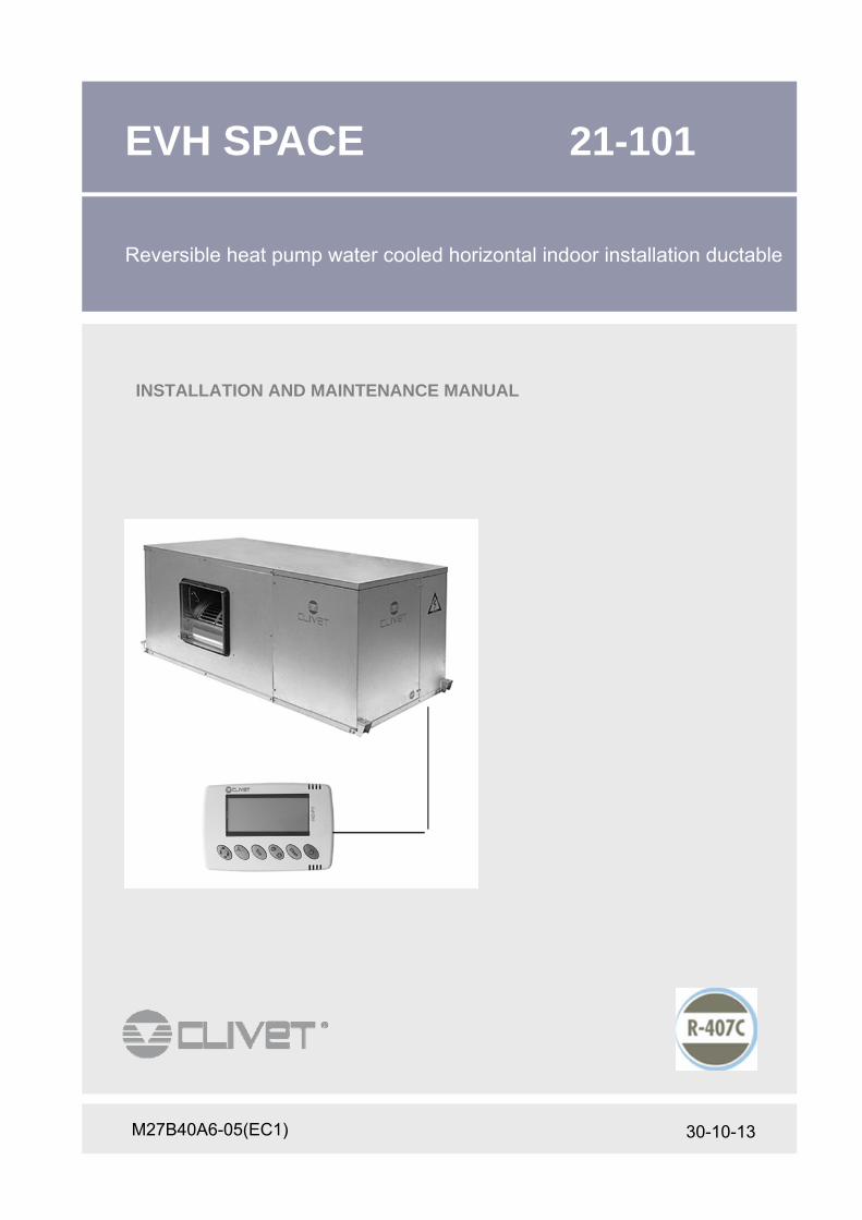
30-10-13
EVH SPACE 21-101
Reversible heat pump water cooled horizontal indoor installation ductable
M27B40A6-05(EC1)
INSTALLATION AND MAINTENANCE MANUAL
2
Dear Customer, We congratulate you on choosing an ELFOSystem product, the air conditio-ning system at annual cycle that offers the possibility in a sole system of meeting all the heating, conditioning and domestic hot water needs. Clivet is being working for years to offer systems able to assure the maxi-mum comfort for long time with high reliability, efficiency , quality and safety. The target of the company is to offer advanced systems, that assure the best comfort, reduce the energy consumption, the installation and main-tenance costs for all the life-cycle of the system. With this manual, we want to give you information that are useful in all the phases: from the reception, to the installation and use until the disposal so that a system so advanced offers the best procedure of installation and use. Best regards and have a nice reading ! CLIVET Spa
The data contained in this manual is not binding and may be changed by the manufacturer without prior notice.
All reproduction, even partial, is prohibited.
3
INDEX
1
2
3
4
General 4
Riception 6
Positioning 7
Water connections 9
Electrical connections 12
Start-up 5
Control 18
Maintenance 21
Residual risks 24
Decommissioning 25
Technical information 26
Aeraulic connections 11
5
6
7
8
9
10
11
12
4
1 - GENERAL
1.2 GENERAL INSTRUCTIONS
Preliminaries
The positioning, hydraulic system, refrigerating, electrics and
the channelization of the air must be determined by the
system designer in accordance with the local regulations.
Only qualified personnel can operate on the unit, as required
by the regulation in force.
Using the unit in case of breakdown or malfunction
• voids the warranty
• may compromise the safety of the machine
• may increase time and repair costs.
Follow local safety regulations.
Keep packing material out of children’s reach it may be
dangerous.
Recycle and dispose of packing material in conformity with
local regulations.
Risk situations
The unit has been designed and created to prevent injures to
people.
During designing it is not possible to plane and operate on all
risk situation.
Read carefully "Residual risk" section where all situation
which may cause damages to things and injuries to people
are reported.
Installation, starting, maintenance and repair required specific
knowledge; if they are carried out by inexperienced personnel,
they may cause damages to things and injuries people.
Intended use Use the unit for the:
- air treatment. Follow the limits defined in the technical bulletin and on this manual.
Not treat air containing :
• high concentration of dust;
• aggressive substances ;
• residual of industrial processes.
Any use other than intended does not involve the
manufacturer in any commitment or obligation.
Installation Verify that the electrical line characteristics are in compliance
with data quotes on the unit serial number label.
Maintenance Plan periodic inspection and maintenance in order to avoid or
reduce repairing costs.
Turn the machine off before any operation.
Modification All unit modifications will end the warranty coverage and the
manufacturer responsibility.
Breakdown/Malfunction
Disable the unit immediately in case of breakdown or
malfunction.
Contact a constructor certified assistance service
Use original spares parts only. .
User training
The installer has to train the user on :
• start-up / shutdown;
• set points change;
• standby mode;
• Maintenance;
• what to do / what not to do in case of breakdown.
Data update
Continual product improvements may imply manual data
changes
Visit manufacturer web site for updated data.
Keep this manual with the wiring diagram in an accessible
place for the operator.
Note the unit label data so you can provide them at the
assistance centre in case of intervention (see "Unit
identification" section)
Provide a machine notebook that allows any interventions
carried out on the machine to be noted and tracked making it
easier to suitably note the various interventions and aids the
search for any breakdowns.
• In case of breakdown or malfunction:
• immediately deactivate the unit.
• Contact a constructor certified assistance service.
• Use original spares parts only.
Ask the installer to format on:
• start-up / shutdown
• set points change
• standby mode
• maintenance
• what to do / what not to do in case of breakdown
1.3 INDICATIONS FOR THE USER
The manual provides correct unit installation, use and
maintenance.
Fare particolare attenzione ad :
WARNING indicate particularly important operations or
information.
PROHIBITED indicate operations that must not be carried out,
that compromise the operating of the equipment or may cause
damage to persons or things.
• It is advisable to read it carefully so you will save time
during operations.
• Follow the written indications so you will not cause
damages to things and injuries people. The preliminary
information must be read prior to carrying out any of the
following operations.
1.1 MANUAL

5
1 - GENERAL
1.4 UNIT IDENTIFICATION
Serial number label The serial number label is positioned on the unit and allows to
indentify all the unit features.
It has not to be removed for any reason.
It reports the regulations indications such as:
• Machine type series → EVH-SPACE
• Size → 21 ....101
• Serial number xxxxxxxxxxxx
• Year of manufacture
• Wiring diagram number
• Electrical data
• Manufacturer logo and address
Serial number It identifies uniquely each machine.
It identifies specific spare parts for the machine
Assistance requests Note data from the serial number label and write them in the chart on side, so you will find them easily when needed.
In case of intervention you have to provide data
Serie
Size
Serial number
Year of manufacture
Wiring diagram

6
Sollevamento con forche:
• Inserire le forche come indicato in figura.
• È vietato sollevare più colli contemporaneamente
lasciandoli sciolti.
• In caso di sollevamento di più unità contempora-
neamente deve essere utilizzato un contenitore
idoneo.
2 - RECEPTION
Generali Operare rispettando le normative di sicurezza in vigore.
Per le informazioni di dettaglio (dimensioni, pesi,
caratteristiche tecniche, etc) far riferimento al capitolo
INFORMAZIONI TECNICHE.
Per effettuare le operazioni usare dispositivi di
protezione: guanti , occhiali ecc.
Stoccaggio Rispettare le indicazioni riportate sull’esterno
dell’imballo.
Movimentazione Verificare peso dell’unità e capacità del mezzo di
sollevamento.
Individuare i punti critici nel percorso di
movimentazione : percorsi sconnessi, rampe, scalini,
porte.
Considerare che il baricentro potrebbe essere spostato
rispetto al centro dell'unità .
Assicurarsi che l’unità sia in equilibrio stabile.
Rimozione imballo Fare attenzione a non danneggiare l’unità.
Riciclare e smaltire il materiale di imballaggio secondo le norme locali.
2.1 INFORMAZIONI PRELIMINARI
Prima di accettare la consegna controllare:
• Che l’unità non abbia subito danni nel trasporto
• Che il materiale consegnato corrisponda a quanto
indicato sul documento di trasporto confrontando i
dati con l’etichetta matricolare ‘A’ posizionata
sull’imballo.
In caso di danni o anomalie :
• annotare immediatamente sul documento di tra-
sporto il danno riscontrato e riportare la dicitura:
“Ritiro con riserva per evidenti ammanchi/danni da
trasporto”.
• contestare via fax e con raccomandata A.R. al vet-
tore e al fornitore.
Le contestazioni devono essere effettuate entro 8 gior-
ni dal ricevimento, le segnalazioni oltre tale termine
non sono valide.
2.2 CONTROLLO ALL’ARRIVO
2.3 MOVIMENTAZIONE CON IMBALLO
• Tagliare le reggette di fissaggio.
• Rimuovere l’imballo sollevandolo verso l’alto.
• Rimuovere il nylon di protezione.
2.4 RIMOZIONE IMBALLO
A
30°
7
3 - POSITIONING
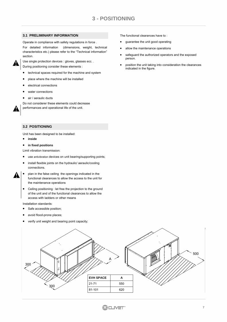
A
300
300
500
EVH SPACE A
21-71 550
81-101 620
Unit has been designed to be installed:
• inside
• in fixed positions
Limit vibration transmission:
• use antivibration devices on unit bearing/supporting points;
• install flexible joints on the hydraulic/ aeraulic/cooling
connections.
• plan in the false ceiling the openings indicated in the
functional clearances to allow the access to the unit for
the maintenance operations
• Ceiling positioning : let free the projection to the ground
of the unit and of the functional clearances to allow the
access with ladders or other means
Installation standards:
• Safe accessible position;
• avoid flood-prone places;
• verify unit weight and bearing point capacity;
Operate in compliance with safety regulations in force .
For detailed information (dimensions, weight, technical
characteristics etc.) please refer to the “Technical information”
section.
Use single protection devices : gloves, glasses ecc. .
During positioning consider these elements :
• technical spaces required for the machine and system
• place where the machine will be installed
• electrical connections
• water connections
• air / aeraulic ducts
Do not considerer these elements could decrease
performances and operational life of the unit.
3.1 PRELIMINARY INFORMATION
3.2 POSITIONING
The functional clearances have to :
• guarantee the unit good operating
• allow the maintenance operations
• safeguard the authorized operators and the exposed person.
• position the unit taking into consideration the clearances indicated in the figure.

8
3 - POSITIONING
Hanging
in support
The choice of the installation point is important for the
comfort of the served area and the energy consumptions.
The thermostat must be positioned:
• in a room with medium temperature and humidity
conditions, representative of the other rooms;
• at a height of 150 cm;
• preferably on an inner wall;
Positions to avoid:
• near heat sources;
• exposed to direct solar radiation;
• in a position with exhaust air from outlets or diffusers;
• behind curtains or pieces of furniture;
• - near doors and windows to the outside;
• - on walls crossed by heating chimneys or pipes;
• - on external walls.
3.3 THERMOSTAT POSITIONING (OPTIONAL)
(1) Tapped bar M10 (M12 for sizes 81-91-101)
(2) galvanized steel nuts
(3) galvanized steel plain washer Ø external 30mm
(4) rubber plain washer Ø external 30mm thickness 6mm
(5) Anti-vibration rubber or spring
(6) galvanized steel plain washer Ø external 40mm

9
4 - WATER CONNECTIONS
4.4 CONDENSE DRAIN
The condense must be disposed of in order to avoid
damaging things and persons. • Unit drain coupling: the connection must not transmit
mechanical stresses and must be carried out paying
attention not to damage the unit drain coupling.
• Foresee a siphon that, by eliminating the depression
caused by the fan, prevents suction of air from the drain
piping.
• The piping must have adequate slope to allow out flow.
• Anchor the piping with an adequate number of supports.
• On the contrary, cracking in the piping and air pockets
obstructing the outflow, are generated.
• Isolate piping and siphon to avoid condense dripping.
• Connect the condense drain to a rain drain network.
• DO NOT use white waters or sewage drains to avoid
possible inhaling of odours in case of evaporation of the
water contained in the si phon.
• At work end, check the regular outflow of the condense by
pouring water in the bowl. i
Example :
P = 300 Pa = 30 mm
T = 2P = 60 mm
S = T/2 = 30 mm
Siphon height calculation T = 2P
S = T/2
P is the pressure determined by the fan in correspondence of
the condense collection bowl (approx. 1 mm = 9.81 Pa)
4.1 PRELIMINARY INFORMATION
Selection and installation of system components must be
carry out by installer.
Following a series of instructions that must be integrated with
what required by local regulations and by the code of practise.
INTERCEPTING VALVES
• Installed on the input and output, they allow to carry out all
the maintenance operations and possible without emptying
the installation.
THERMOMETERS AND PRESSURE GAUGES:
• Installed on the input and output of the main parts facilitate
the controls and the maintenance.
BLEED VALVES :
• Installed in all the highest points of the system, they allow
the venting from the circuit.
BLEEDING COCKS :
• Installed at the lowest points of the circuit, so as to allow
emptying .
EXPANSION TANK :
• It allows the system correct pressure to be maintained at
the water temperature changing. It has to be sized
according to the system water content.
WATER FILTER :
• If it is not built-in, it has to be immediately installed at the
unit water inlet, in a position easily accessible for cleaning.
• The filter should never be removed, the operation will void
the warranty.
SUPPORTS :
• for the weight of the water piping that must not rest on the
unit fittings.
FLOW SWITCH
• as a component of the system must always be provided.
4.2 COMPONENTS
4.3 OPERATION SEQUENCE
Before connecting the unit, carefully wash the system by filling
it and emptying it several times with clean water.
Ignoring this operation will lead to several filter cleaning
interventions and at worst cases can cause damages to the
exchangers and the other parts.
Execute leakage test before isolate the pipes.
To avoid heat dispersions and formation of condensate isolate
all the pipes.
Leave various point of service free (wells, vent-holes etc )
i
i
Adopt measures to prevent risk of freezing if the unit or
relative hydraulic connections can be subject to temperatures
near 0°C. • isolate the piping
• protect the piping with heating cables laid underneath
the insulation
4.5 RISK OF FREEZING
!
10
4 - WATER CONNECTIONS
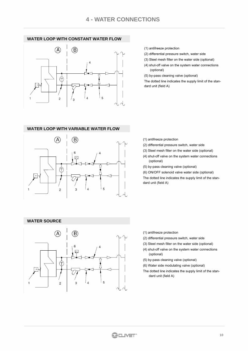
WATER LOOP WITH CONSTANT WATER FLOW
WATER LOOP WITH VARIABLE WATER FLOW
WATER SOURCE
(1) antifreeze protection
(2) differential pressure switch, water side
(3) Steel mesh filter on the water side (optional)
(4) shut-off valve on the system water connections
(optional)
(5) by-pass cleaning valve (optional)
The dotted line indicates the supply limit of the stan-
dard unit (field A)
(1) antifreeze protection
(2) differential pressure switch, water side
(3) Steel mesh filter on the water side (optional)
(4) shut-off valve on the system water connections
(optional)
(5) by-pass cleaning valve (optional)
(6) ON/OFF solenoid valve water side (optional)
The dotted line indicates the supply limit of the stan-
dard unit (field A)
(1) antifreeze protection
(2) differential pressure switch, water side
(3) Steel mesh filter on the water side (optional)
(4) shut-off valve on the system water connections
(optional)
(5) by-pass cleaning valve (optional)
(6) Water side modulating valve (optional)
The dotted line indicates the supply limit of the stan-
dard unit (field A)
11
5 - AERAULIC CONNECTIONS
5.1 GENERAL
Proper execution and sizing of air connections are essential
for ensuring correct operation of the unit and an acceptable
level of silence in the room.
When designing and creating ducts, consider PRESSURE
DROPS, FLOW RATE and AIR SPEED which need to be
compatible with the characteristics of the unit.
Special consideration needs to be made for pressure drops
that are greater than the unit's static pressure, which would
lead to a reduction in flow rate resulting in unit shutdown.
• the weight of the ducts must not be supported by the
connection flanges
• place anti-vibration joints between the ducts and the unit
• the connection to the flanges and between the various
sections of the ducts must ensure an airtight seal, preven-
ting leakage in delivery and return which would compromi-
se overall system efficiency.
• limit pressure drops by optimizing the path, the type and
number of curves and the branches
• use curves with a wide radius. Consider whether it might
be useful to equip them with deflectors (especially if the air
speed is high or if curves are tight )
• The inner surface of the duct must be smooth and washa-ble. It must not contaminate the air.
• Thermally insulate the ducts and the flanges so as to pre-vent loss of energy and condensation build-up.
GRILLES OUTLETS DIFFUSERS
Proper distribution of air in the room is essential for ensuring comfort levels.
In the selection and positioning of grilles, outlets and diffusers, the following are to be avoided:
• excessive air speed
• formation of stagnant zones and layering
• entry of cold air into the room
• formation of localized currents (due to uneven air distribution)
• excessive variations in ambient temperature in the vertical and horizontal planes
• short circuiting of delivery air towards return air
For purposes of comfort, the following things need to be consi-dered:
• air diffusers must be selected by checking the sound power generated at nominal flow rate conditions
• the disconnections to the diffusers are to be made using flexible elements
• the return grilles must be amply sized
APPLICATIONS AT HIGH DEGREE OF SILENCE
For applications that require a high degree of silence in the system:
• In delivery and return, provide septum silencers, pre-ferably inserted in sections of ducts located outside the building.
• Equip all curves with deflectors.
5.2 FEATURES FOR DUCTS FOR TREATED AIR

12
6 - ELECTRICAL CONNECTIONS
General
• The characteristics of the electrical lines must be
determined by specialized personnel able to design
electrical installations; moreover, the lines must be in
conformity with regulations in force.
• Please refer to the "Information" section for the detailed
characteristics of the apparatus (dimensioning,
performance, etc) .
• Operate in compliance with safety regulations in force .
• Use single protection devices : gloves, glasses ecc….
• The protection devices of the unit power line must be able
to stop the presumed short circuit current, whose value
must be determined in function of system features
• The power cables and the protection cable section must
be defined in accordance with the characteristics of the
protections adopted.
• The electrical data indicated in the technical bulletin and in
the manual refer to the standard unit, accessories
excluded.
The serial number label reports the unit specific electrical
data, included any electrical accessories.
Refer therefore to the electrical data indicated on the
serial number label.
Connections
• All electrical operations should be performed by trained
personnel having the necessary requirements by the
regulations in force and being informed about the risks
relevant to these activities.
• Refer to the unit electrical diagram (the number of the
diagram is shown on the serial number label).
• Verify that the network has characteristics conforming to
the data shown on the serial number label .
• Shelter the cables using adequate measure fairleads.
• Before starting work, verify that the sectioning device at
the start of the unit power line is open, blocked and
equipped with sign warning.
• First create the earthing connection.
• Prior to powering the unit ensure that all the protections
that were removed during the electrical connection work
have been restored.
Signal lines/data-lay
• Do not overpass the maximum power allowed, which
varies, according to the type of signal.
• Lay the cables far from power cables or cables having a
different tension and that are able to emit electromagnetic
disturbances.
• Do not lay the cable near devices which can generate
electromagnetic interferences.
• Do not lay the cables parallel to other cables; cable
crossings are possible, only if laid at 90°.
• Connect the screen to the ground, only if there aren’t
disturbances .
• Guarantee the continuity of the screen for the entire
extension of the cable.
• Respect impendency, capacity and attenuation indications.
6.1 PRELIMINARY INFORMATION
6.2 POWER SUPPLY INPUT
Fix the cables: if vacated may be subject to tearing.
The cable don't have to touch the compressor and the
refrigerant piping ( they reach high temparatures ).

13
6 - ELECTRICAL CONNECTIONS
WITH A PERMISSIBLE TOLERANCE
Make sure that the sectioning device at the beginning of the unit’s power line is opened, locked and equipped with a signal.
Open the general line disconnecting switch (if present)
Verify that the net is in conformity with the data shown in the registration plate placed on the electrical board.
Check the dimensional drawing for the input of the electrical lines
Take away the closing plate placed on the electric board (ONLY IF PRESENT) and drill a hole through it to pass the cables
through.
Protect the cables, using the fairlead of an adequate size.
Using the layout of the electrical diagram, single out the connecting terminals of the electrical supply cables, of the neutral
(if foreseen) and the PE protection cable
Connect the cables to the relevant terminal boards
Before supplying power to the unit, make sure that all the safety devices that were removed during electrical connections are
positioned again.
FUNCTIONAL CONNECTIONS
FOR ALL CONNECTIONS REFER TO THE WIRING DIAGRAM ENCLOSED WITH THE UNIT
Use voltage-free remote control devices that are suitable to commutate very low loads (12V, 10mA).
Few inputs must be activated by configuration parameters whose access is reserved to authorized assistance
centers (in order to avoid unauthorized modifications).
ON / OFF FROM REMOTE CONTROL
Generally the unit is delivered with bridged terminals; if the control is not used, the bridge should not be removed.
CHANGING FROM SUMMER TO WINTER USING THE REMOTE CONTROL
Only if the hot water coil or electric heaters are present.
This function is activated with the RemMode = 1 parameter.
Selection switch open – unit in heating mode, selection switch closed – unit in cooling mode, this way the keyboard or su-
pervisor unit selection is deactivated.
SET ECO USING THE REMOTE CONTROL
This function is activated with the RemMode = 1 parameter.
In this way the keyboard or supervisor unit selection is deactivated.
VENTILATION ONLY USING THE REMOTE CONTROL
This function is activated with the RemMode = 1 parameter.
In this way the keyboard or supervisor unit selection is deactivated.
FIRE ALARM INLET
Generally the unit is delivered with bridged terminals; if the control is not used, the bridge should not be removed.
SIGNALIZATION OF MALFUNCTIONING/ UNIT FUNCTIONING
Remote signalization of the proper function (ex. green light) or signalization of blocks of the machine (ex. red light).
Maximum voltage at the terminal ends is 24v ac and maximum power is 5A (AC1).
REMOTE KEYPAD
Signal conductor signal: 2 + SHIELD
Min. section: 0.34 MM2
Max. length: 100 METRES
voltage: 230/1/50
HID-P1 ROOM THERMOSTAT
Conductor number: 3 + SHIELD
Min. section: 0.34 MM2
Max. length: 100 METRES
14
6 - ELECTRICAL CONNECTIONS
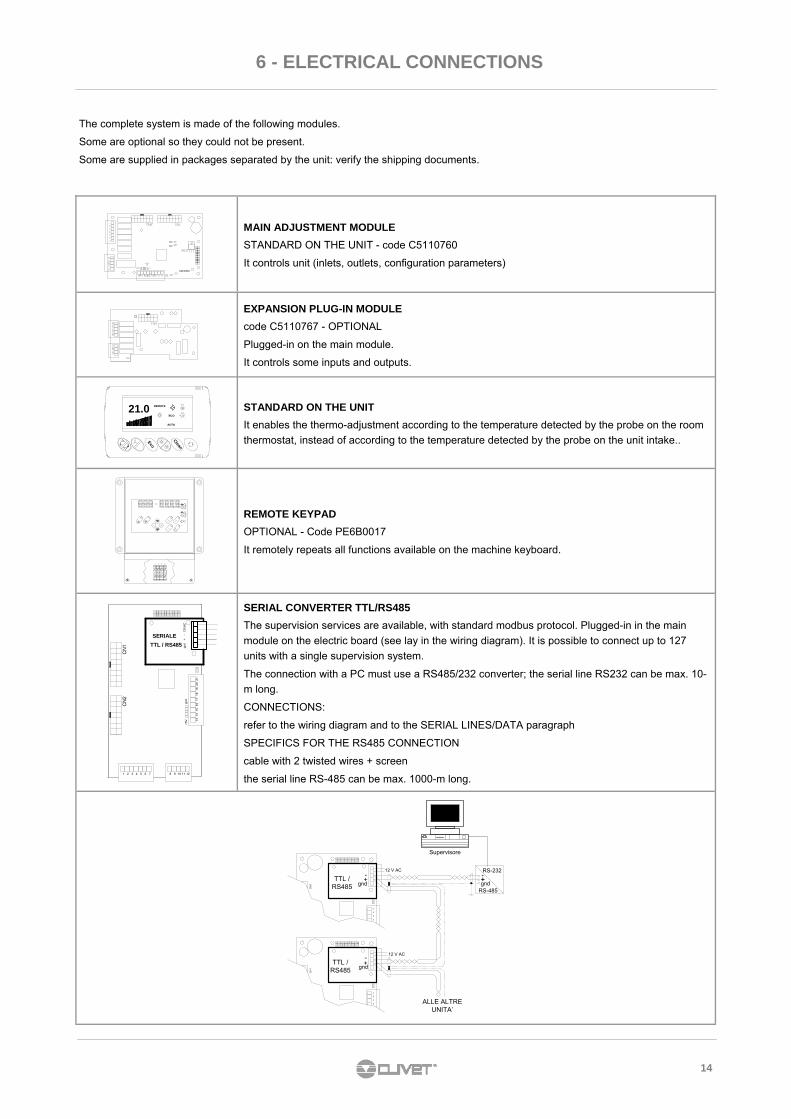
The complete system is made of the following modules.
Some are optional so they could not be present.
Some are supplied in packages separated by the unit: verify the shipping documents.
MAIN ADJUSTMENT MODULE
STANDARD ON THE UNIT - code C5110760
It controls unit (inlets, outlets, configuration parameters)
EXPANSION PLUG-IN MODULE
code C5110767 - OPTIONAL
Plugged-in on the main module.
It controls some inputs and outputs.
Eco
21.0
Clean
REMOTE
ECO
AUTO
STANDARD ON THE UNIT
It enables the thermo-adjustment according to the temperature detected by the probe on the room
thermostat, instead of according to the temperature detected by the probe on the unit intake..
L N 91 92
STAT
US
SET
ALARM
2
1
REMOTE KEYPAD
OPTIONAL - Code PE6B0017
It remotely repeats all functions available on the machine keyboard.
81 2 3 4 5 6 7
CN
2
12109 11
16
+5
V 13
14
15
gn
d
19
17
18
21
20
SERIALE
TTL / RS485
CN
1 gn
d1
2V
AC
+-
SERIAL CONVERTER TTL/RS485
The supervision services are available, with standard modbus protocol. Plugged-in in the main
module on the electric board (see lay in the wiring diagram). It is possible to connect up to 127
units with a single supervision system.
The connection with a PC must use a RS485/232 converter; the serial line RS232 can be max. 10-
m long.
CONNECTIONS:
refer to the wiring diagram and to the SERIAL LINES/DATA paragraph
SPECIFICS FOR THE RS485 CONNECTION
cable with 2 twisted wires + screen
the serial line RS-485 can be max. 1000-m long.
12 V AC
CN
1C
N1
191
82
02
12
01
81
92
1
RS-485
RS-232
gnd
-
+
Supervisore
TTL /RS485
+
-
ALLE ALTREUNITA’
12 V AC
gnd
TTL /RS485
-
gnd
+

15
7- START-UP
Preliminary checks
Checks with machine in OFF, before start-up . For details refer to the various chapters in the manual.
Start-up sequence
Machine start-up operations.
For details refer to the various chapters in the manual.
√ Unit OFF power supply
• safe access
• functional spaces
• integrity of structure
• unit on anti-vibration devices
• air filters present and clean
• completed idraulic system
• cooling circuit visual control
• earth connection
• unit powered by fixed network or by electrogen group
• electric connections by customer
√ unit ON power supply
• Powered unit
• compressor carter heaters ON from at least 8 hours
• phases sequence control
• vacuum voltage measurement
• unit ON
• load voltage measurement and absorptions
• treated air flow rate measurement
• supply, return and outdoor air temperature measurement
• subcooling and overheating measurement
• no anomalous vibrations check
• set-point customisation
• available machine documentation

16
7- START-UP
!
7.1 PRELIMINARY INFORMATION
The indicated operations must be carried out by qualified
technicians and specifically trained on the product.
Upon request, the after-sales assistance centres execute start-
up.
The electric, hydraulic connections and the other work of the
system are the responsibility of the installer.
Agree the start-up date with the after-sales assistance centre
with sufficient advance
Check the unit is connected to the earth system. Check
fastening of the conductors: the vibrations caused by handling
and transport may cause loosening.
Power the unit by closing the isolation device but leave in
OFF.
Check the network frequency and voltage values, that are
within the limits:
400/3/50 +/- 10%
Check the unbalancing of the phases: must be below 2% .
Example : 7.2 PRELIMINARY CHECKS
7.3 COOLING CIRCUIT
7.4 HYDRAULIC CIRCUIT
7.5 ELECTRIC CIRCUIT
Before starting any check, verify that : • the unit is perfectly installed and in compliance with that
reported in this manual
• the electric power supply line of the unit is isolated at start-
up
• the isolation device of the line is open, blocked and
equipped with relative signal.
1. Visually check the cooling circuit: any oil stains can be
symptom of leaks (caused by, for example, transport,
handling or other).
2. Check the cooling circuit is pressurised: use the machine
pressure gauges, if present, or service pressure gauges.
3. Check all service sockets are closed with relative plugs;
their absence may determine coolant leaks
Glycol in weight (%) 10 20 30 40
Freezing temperature (°C) -3.9 -8.9 -15.6 -23.4
Safety temperature (°C) -1 -4 -10 -19
Operation outside the limits can entail irreversible damages.
L1 L2 L3
388V
379V
377V
388 + 379 + 377
3= 381 (A)
MAX - A = 388 – 381 = 7
S =7
Ax 100 = 1,83 OK
1)
2)
3)
7.6 COMPRESSOR CARTER RESISTORS
Power the compressor oil heating resistors for at least 8 hours
before starting the compressor itself:
• upon unit commissioning
• after every prolonged stop period with unit not
powered
Power the resistors by closing the unit isolator.
Check electric absorption of the resistors to be sure they are
working.
Execute start only if the temperature of the compressor casing
on the lower side is at least 10°C higher than the outdoor
temperature.
Do not start the compressor with carter oil not in temperature.
!
!
1. Find out if, before connecting the unit, the hydraulic
system has been washed and the washing water drained.
2. Check the hydraulic circuit has been loaded and
pressurised.
3. Check the shut-off valves on the circuit are in "OPEN"
position.
4. Check there is no air inside the circuit, eventually bleed it
through the vent valves in the high points of the system.
5. In case of using solutions to be cooled, check the
percentage is suitable for the type of use.
17
7- START-UP
Check the air and water temperatures are within the operatio-
nal limits.
Start the unit; refer to the "Adjustment" section for indications
on the control system.
With the unit running, meaning in stable conditions and near
the work ones, check:
• power supply voltage
• unit overall absorption
• absorption of the individual electric loads.
7.7 VOLTAGES
The Scroll compressors have only one rotation direction.
In the event it is reversed, the compressor is not immediately
damaged, but increases its noise and jeopardises pumping.
After a few minutes, the compressor blocks due to intervention
of the thermal protection. In this case, disconnect power
supply and invert 2 phases on the machine power supply.
Avoid the compressor working for a long time with contrary
rotation: more than 2-3 of these anomalous start-ups can
damage it.
To ensure the rotation direction is correct, measure the
condensation and suction pressure. The pressures must
significantly differ: upon start-up, the suction pressure
decreases whereas the condensation one, increases.
The phase monitor optional, controlling the phases sequence,
can also eventually be installed subsequently.
7.8 ROOM PRESSURE CALIBRATION
Check the remote controls (ON-OFF, etc.) are connected
and, if necessary, enabled with relative parameters
(ELECTRIC CONNECTIONS sections and following pages)
Check the probes or optional components are connected and
enabled with the relative parameters.
7.9 REMOTE CONSENTS
i
7.10 START-UP REPORT
To detect the objective operational conditions is useful to
control the unit over time.
With the unit running, meaning in stable conditions and near
the work ones, detect the following data:
• Overall absorptions and voltages with unit in full load
• Absorptions of the various electric loads
(compressors, fans, pumps etc)
• Temperatures and flow rates of the various fluids
(water, air) at input and output of the unit
• Temperatures and pressures in the feature points of
the cooling circuit (compressor, liquid, suction drain/
unload)
The detections must be kept and made available during
maintenance interventions.
7.11 EC DIRECTIVE 97/23 PED
From Directive 97/23 EC PED derive the prescriptions for the
installers, the users and the maintenance operators of the unit
also.
Refer to the local implemented standards; in synthesis and for
merely indicative purposes:
• Compulsory check of first system:
only for units assembled on site by the installer (e.g.
condensing + direct expansion unit)
• Declaration of start-up:
for all units
• Periodical checks:
to be carried out as frequently as defined by the
Manufacturer
(see MAINTENANCE section) .

18
8 - CONTROL
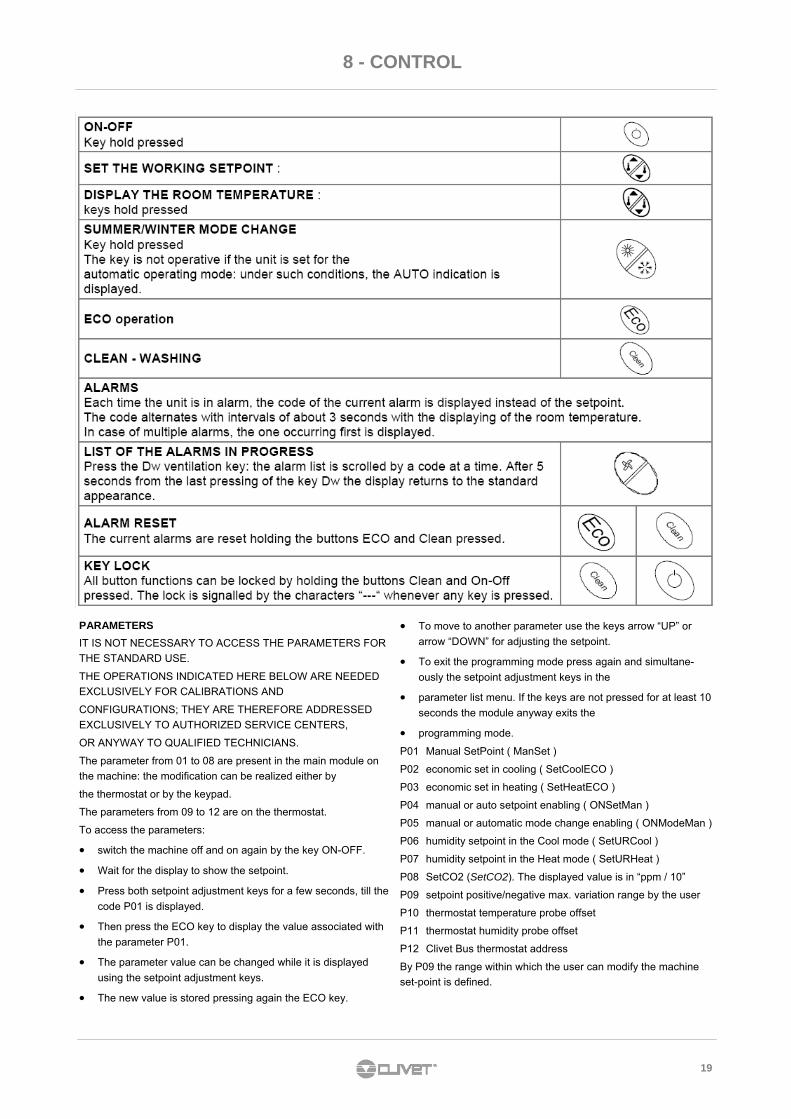
OPERATING MODES
MANUAL
The choice between the HEATING or the COOLING mode is carried out manually by the keypad, the room thermostat or the remote
selector (see the chapter ELECTRICAL CONNECTIONS).
AUTOMATIC
The choice between the HEATING or the COOLING mode is carried out automatically by the electronic module, according to the
room temperature detected by the probe placed on the unit inlet (or on the room thermostat, if present). When temperatures are higher
than the cool set, the unit cools the room; when temperatures are lower than the heat set, it heats the room.
The choice between the automatic and manual change is definite by the parameter num. 1 OnModeMan:
MANUAL = 1 AUTOMATIC = 0
ECO
In this operating mode, lower consumption is preferred to comfort:
The ECO-COOL set is higher than the COOLING set
The ECO-HEAT set is lower that the HEATING set
In this mode, the fan is activated periodically to verify the room temperature and therefore decide to activate or not the available re-
sources to satisfy the set.
It can be activated by the keypad.
CLEAN
The CLEAN mode differs from the VENTILATION ONLY because it can be timed; after the set time, the mode deactivates.
It can be activated by the keypad.
VENTILATION
In VENTILATION ONLY, the unit behaves like a fan: the OUTLET fans are activated and no setting on the room temperature is per-
formed.
It can be activated by the remote selector.
SET-POINT
MANUAL SET POINT
The ambient set point can be MANUALLY modified by the thermostat at P01 parameter
HID-P1 ROOM THERMOSTAT
The unit is designed for the connection with a remote HID-P1 thermostat to be placed in the room.
It is possible to perform the thermoregulation according to the temperature detected by the probe of the room thermostat: it is neces-
sary to take away the probe placed on the unit inlet and to modify the machine configuration (this operation should be performed by an
authorized service centre).
The thermostat displays the set-point on the display.
19
8 - CONTROL
PARAMETERS
IT IS NOT NECESSARY TO ACCESS THE PARAMETERS FOR
THE STANDARD USE.
THE OPERATIONS INDICATED HERE BELOW ARE NEEDED
EXCLUSIVELY FOR CALIBRATIONS AND
CONFIGURATIONS; THEY ARE THEREFORE ADDRESSED
EXCLUSIVELY TO AUTHORIZED SERVICE CENTERS,
OR ANYWAY TO QUALIFIED TECHNICIANS.
The parameter from 01 to 08 are present in the main module on
the machine: the modification can be realized either by
the thermostat or by the keypad.
The parameters from 09 to 12 are on the thermostat.
To access the parameters:
• switch the machine off and on again by the key ON-OFF.
• Wait for the display to show the setpoint.
• Press both setpoint adjustment keys for a few seconds, till the
code P01 is displayed.
• Then press the ECO key to display the value associated with
the parameter P01.
• The parameter value can be changed while it is displayed
using the setpoint adjustment keys.
• The new value is stored pressing again the ECO key.
• To move to another parameter use the keys arrow “UP” or
arrow “DOWN” for adjusting the setpoint.
• To exit the programming mode press again and simultane-
ously the setpoint adjustment keys in the
• parameter list menu. If the keys are not pressed for at least 10
seconds the module anyway exits the
• programming mode.
P01 Manual SetPoint ( ManSet )
P02 economic set in cooling ( SetCoolECO )
P03 economic set in heating ( SetHeatECO )
P04 manual or auto setpoint enabling ( ONSetMan )
P05 manual or automatic mode change enabling ( ONModeMan )
P06 humidity setpoint in the Cool mode ( SetURCool )
P07 humidity setpoint in the Heat mode ( SetURHeat )
P08 SetCO2 (SetCO2). The displayed value is in “ppm / 10”
P09 setpoint positive/negative max. variation range by the user
P10 thermostat temperature probe offset
P11 thermostat humidity probe offset
P12 Clivet Bus thermostat address
By P09 the range within which the user can modify the machine
set-point is defined.
20
8 - CONTROL
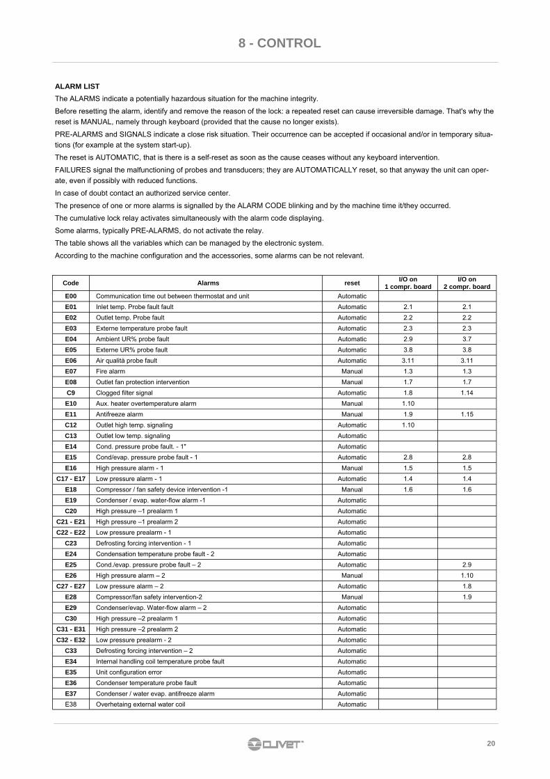
ALARM LIST
The ALARMS indicate a potentially hazardous situation for the machine integrity.
Before resetting the alarm, identify and remove the reason of the lock: a repeated reset can cause irreversible damage. That's why the
reset is MANUAL, namely through keyboard (provided that the cause no longer exists).
PRE-ALARMS and SIGNALS indicate a close risk situation. Their occurrence can be accepted if occasional and/or in temporary situa-
tions (for example at the system start-up).
The reset is AUTOMATIC, that is there is a self-reset as soon as the cause ceases without any keyboard intervention.
FAILURES signal the malfunctioning of probes and transducers; they are AUTOMATICALLY reset, so that anyway the unit can oper-
ate, even if possibly with reduced functions.
In case of doubt contact an authorized service center.
The presence of one or more alarms is signalled by the ALARM CODE blinking and by the machine time it/they occurred.
The cumulative lock relay activates simultaneously with the alarm code displaying.
Some alarms, typically PRE-ALARMS, do not activate the relay.
The table shows all the variables which can be managed by the electronic system.
According to the machine configuration and the accessories, some alarms can be not relevant.
Code Alarms reset I/O on
1 compr. board I/O on
2 compr. board
E01 Inlet temp. Probe fault fault Automatic 2.1 2.1
E02 Outlet temp. Probe fault Automatic 2.2 2.2
E03 Externe temperature probe fault Automatic 2.3 2.3
E04 Ambient UR% probe fault Automatic 2.9 3.7
E05 Externe UR% probe fault Automatic 3.8 3.8
E06 Air qualità probe fault Automatic 3.11 3.11
E07 Fire alarm Manual 1.3 1.3
E08 Outlet fan protection intervention Manual 1.7 1.7
C9 Clogged filter signal Automatic 1.8 1.14
E10 Aux. heater overtemperature alarm Manual 1.10
E11 Antifreeze alarm Manual 1.9 1.15
C12 Outlet high temp. signaling Automatic 1.10
C13 Outlet low temp. signaling Automatic
E14 Cond. pressure probe fault. - 1" Automatic
E15 Cond/evap. pressure probe fault - 1 Automatic 2.8 2.8
E16 High pressure alarm - 1 Manual 1.5 1.5
C17 - E17 Low pressure alarm - 1 Automatic 1.4 1.4
E18 Compressor / fan safety device intervention -1 Manual 1.6 1.6
E19 Condenser / evap. water-flow alarm -1 Automatic
C20 High pressure –1 prealarm 1 Automatic
C21 - E21 High pressure –1 prealarm 2 Automatic
C22 - E22 Low pressure prealarm - 1 Automatic
C23 Defrosting forcing intervention - 1 Automatic
E24 Condensation temperature probe fault - 2 Automatic
E25 Cond./evap. pressure probe fault – 2 Automatic 2.9
E26 High pressure alarm – 2 Manual 1.10
C27 - E27 Low pressure alarm – 2 Automatic 1.8
E28 Compressor/fan safety intervention-2 Manual 1.9
E29 Condenser/evap. Water-flow alarm – 2 Automatic
C30 High pressure –2 prealarm 1 Automatic
C31 - E31 High pressure –2 prealarm 2 Automatic
C32 - E32 Low pressure prealarm - 2 Automatic
C33 Defrosting forcing intervention – 2 Automatic
E34 Internal handling coil temperature probe fault Automatic
E35 Unit configuration error Automatic
E36 Condenser temperature probe fault Automatic
E37 Condenser / water evap. antifreeze alarm Automatic
E00 Communication time out between thermostat and unit Automatic
E38 Overhetaing external water coil Automatic
21
9 - MAINTENANCE
!
9.1 GENERALITY Maintenance must be carried out authorised after-sales
assistance centres or by specialised personnel.
Maintenance allows:
• maintaining the unit efficient
• reduce deterioration speed to which each equipment is
subject in time
• collect information and data to understand the efficiency
state of the unit and prevent possible faults
Frequency of the inspections must be at least six-monthly
However, frequency depends on the type of use.
• heavy (continuous or highly intermittent, near to operation
limits, etc.)
• critical (essential service).
9.2 FREQUENCY OF INTERVENTIONS
9.3 MACHINE SCHEDULE
Foresee a machine schedule to keep trace of the
interventions made on the unit.
In this way, it will be easier to adequately schedule the various
interventions and facilitate any troubleshooting.
On the schedule note:
• date
• type of intervention made
• description of intervention
• measurements taken, etc. .
If foreseen a long period of inactivity: • disconnect voltage to avoid electric risks or damages
following lightning
• prevent the risk of freezing (empty or glycol the sections of
the system exposed to negative temperatures, keep any
antifreeze heaters powered)
It is advised that start-up after a period of inactivity be carried
out by a qualified technician, in particular after seasonal stops
or for seasonal switch-over.
Upon start-up, follow that indicated in the START-UP section.
Plan in advance the technician intervention to prevent
misunderstandings and be able to use the system when
required
9.4 STAND-BY
i
i
It is very important for the exchanger to be able to provide the
maximum thermal exchange. Therefore, it is essential for the
inner surfaces to be clean of dirt and incrustations.
Periodically check the difference between the temperature of
the supply water and the condensation temperature. If the
difference is greater than 8 °C – 10 ° C it is advisable to clean
the exchanger.
The clearing must be effected :
• With circulation opposite to the usual one
• With a speed at least 1,5 times higher than the nominal one
• With an appropriate product moderately acid (95% water + 5% phosphoric acid
• After the cleaning rince with water to inhibe the detergent rests.
9.5 WATER EXCHANGER
9.6 INTERNAL AIR COIL
Accidental contact with the fins of the exchanger may cause
small cuts. When performing the following steps, use
protective gloves.
The finned surfaces of the cooling coils and especially the
condensation collection trays are the places where micro-
organisms and moulds most easily flourish. It is therefore
very important to clean regularly with suitable detergents and
disinfect with appropriate products as necessary.
Dust and deposits could cause obstructions .
In the tank can also proliferate microorganisms and mold.
Very important to provide for a periodic cleaning with
appropriate detergents and in case to a disinfection with
sanitizing products.
Clean the tank, pour some water into the tank and check
water flows normally.
9.7 CONDENSATE DISCHARGE
22
9 - MAINTENANCE
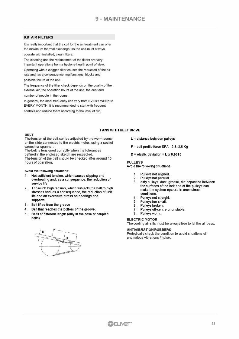
9.8 AIR FILTERS
It is really important that the coil for the air treatment can offer
the maximum thermal exchange: so the unit must always
operate with installed, clean filters.
The cleaning and the replacement of the filters are very
important operations from a hygiene-health point of view.
Operating with a clogged filter causes the reduction of the air
rate and, as a consequence, malfunctions, blocks and
possible failure of the unit.
The frequency of the filter check depends on the quality of the
external air, the operation hours of the unit, the dust and
number of people in the rooms.
In general, the ideal frequency can vary from EVERY WEEK to
EVERY MONTH. It is recommended to start with frequent
controls and reduce them according to the level of dirt.

23
9 - MAINTENANCE
9.9 RECOMMENDED PERIODICAL CHECKS SHEET
Notes/interventions recommended to Owner
*European regulation 303/2008:
Refer to the local implemented standards; in synthesis and for merely indicative purposes, the regulation prescribes the following.
Companies and technicians carrying out installation, maintenance/repair interventions, leaks check and recovery must be CERTIFIED as
foreseen by the local standards.
The leaks check must be carried out on a yearly basis
Checks carried out on…………………….......by……………………………...………….company…..............…………………………………………….
√ intervention frequency (months) 1 6 12
□ presence corrosion
□ panel fixing
□ coil cleaning
□ bowl cleaning + sanitisation
□ outflow test
□ air filters cleaning/inspection
□ air flow rate measurement
□ channelling: anti-vibration devices and fastenings check
□ power supply cable isolation and fastening check
□ earth cable check
□ electric control board cleaning
□ power remote controls state
□ clamps closure, cables isolation integrity
□ phases unbalancing and power supply voltage (vacuum and loaded)
□ absorption of the individual electric loads
□ compressors carter heaters test
□ leaks control *
□ cooling circuit work parameters detection
□ four-way valve exchange check
□ protective equipment test: safety valves, pressure switches, thermostats, flow meters, etc.
□ protective equipment test: setpoint, climatic compensations, power slicing, air flow rate variations
□ control devices test: alarms signal, thermometers, probes, pressure gauges, etc.
□ electrical heaters check - option
□ water coil check - option

24
10 - RESIDUAL RISKS
Generality
The most common situations, as they cannot be controlled by the
manufacturer, that may give rise to risk situations for things or persons
are found in this section.
Dangerous area
It is the area in which only an authorised operator can act. The
dangerous area is the area inside the unit, accessible only via removal of
the cowling or parts of it.
Handling
The handling operations, if carried out without all the necessary safety
devices and without the due caution, can cause the falling or overturning
of the unit with consequent damages, even serious, to things, persons
and the unit itself.
Handle the unit following the instructions on the packaging, in this
manual and according to the local standards in force.
In case of coolant gas leak, refer to the coolant "Safety sheet".
Installation
An incorrect installation of the unit can cause water leaks, condense
storage coolant leaks, electric shocks, fires, malfunctioning or damages
to the unit itself.
Check installation is carried out only by qualified technical personnel and
that the instructions in this manual and the local standards in force are
complied with.
The unit installation in a place where, even occasionally, the flammable
gas leaks and consequent storage of these gases in the area around the
unit itself, can cause explosions and fires.
Installation of the unit in an unsuitable place to support the weight and/or
guarantee an adequate anchoring, can cause the falling and/or
overturning, with consequent damages to things, persons or the unit
itself.
Carefully check positioning and anchoring of the unit.
The easy access to the unit by children, unauthorised persons or
animals, may give rise to accidents and injuries, even serious.
Install the unit in places accessible only by authorised personnel and/or
foresee protections against intrusions in the dangerous area.
General risks
Burnt odour, smoke or other signs of serious anomalies may show the
arising of situations that can cause damages to things, persons or the
unit itself.
Electrically isolate the unit (yellow-red isolator).
Contact the after-sales authorised assistance centre to identify and
resolve the problem at origin of the anomaly.
The accidental contact with exchange coils, compressors, supply piping
or other components can cause injuries and/or burns.
Always wear adequate clothing that includes protective gloves for
operations inside the dangerous area.
Maintenance and repair operations carried out by unqualified personnel
can cause damages to things, persons or the unit itself.
Always contact a qualified after-sales assistance centre.
The lack in closing the unit panels, or lack in checking the correct
fastening of all fastening screws of the panelling, can cause damages to
things, persons or the unit itself.
Periodically check closing of all panels and their correct fastening.
In the event of fire, the coolant temperature can reach values such to
bring the pressure over the safety value, with consequent possible
projection of coolant or explosions of the circuit that remain isolated from
closure of the cocks.
Do not stand near the safety valve and never leave the cooling system
cocks closed.
Electrical part
An incomplete connection line to the electric mains and/or with
incorrectly dimensioned cables, and/or with inadequate protective
equipment, can cause electric shocks, intoxication, damages to the unit
or fires.
Carry out all work on the electric system with reference to the wiring
diagram and this manual, assuring use of a dedicated system.
An incorrect fastening of the lid of the electric components can favour
entry of dust, water, etc. inside and consequently cause electric shocks,
damages to the unit or fires.
Always securely fasten the lid to the unit.
The metal masses of the unit, when powered and not correctly
connected to the earth system, can cause electric shocks or death for
electrocution.
Carefully execute connection to the earth system.
Contact with the accessible powered parts inside the unit after the
removal of guards can cause electric shocks, burns or death for
electrocution.
Open and padlock the main isolator before removing the guards and
signal the works in progress with relative sign.
Contact with parts that may power due to unit start-up, can cause electric
shocks, burns or death for electrocution.
When not necessary.
Moving parts
Contact with the transmissions or suction of the fans can cause injuries.
Before accessing inside the unit, open the isolator on the unit connection
line, padlock it and expose appropriate sign.
Contact with the fans can cause injuries.
Before removing the protective grilles or fans, open the isolator on the
unit connection line, padlock it and expose relative sign.
Coolant
The intervention of the safety valves and the consequent coolant gas
expulsion can cause injuries and intoxication. Always wear adequate
clothing and protective goggles for operations inside the dangerous area.
In case of coolant gas leak, refer to the coolant "Safety sheet".
Contact between naked flames or sources of heat with coolant, or the
heating of the pressurised gas circuit (e.g. during welding), can cause
explosions or fires.
Do not place any source of heat inside the dangerous area.
The maintenance or repair interventions requiring welding must be done
with system drained.
Hydraulic part
Defects in the piping, in the connections or in the shut-off parts, can
cause water leaks or projections, with consequent damages to things or
short circuits of the unit.
25
11 - DISPOSAL
FOR DISMANTLING AND DISPOSING THE UNIT MUST
ALWAYS BE DELIVERED TO AUTHORISED CENTRES.
During dismantling, the fan, the motor and the coil, if working,
may be recovered by the specialised centres for an eventual
reuse.
All materials must be recovered or disposed or in compliance
with the relative national standards in force.
For further information on the dismissal of the unit, contact the
manufacturing company.
11.1 DISCONNECTION The disconnection operations must be carried out by qualified technicians. • Avoid pouring or leaking in room.
• Before disconnecting the unit recover, if present: : - the coolant gas
- solutions to be cooled present inside the hydraulic circuits
• While awaiting dismantling and disposal, the unit can be
stored, even outdoor, as bad weather and temperature
changes do not cause damaging effects for the
environment, as long as the unit has the electric, cooling
and hydraulic circuits intact and closed.
The units falling within the standard in question are marked
with the symbol at the side.
With a view of respecting the environment, our units are
manufactured in accordance with EC Directive on waste
electric and electronic equipment (WEEE).
The potential effects on the environment and on personal
health, due to the presence of dangerous substances, are
reported inside the use and maintenance manual, in the
residue risks section.
If necessary, additional information to that listed below can be
requested from the manufacturer/distributor/importer, as
responsible for the collection/treatment of waste deriving from
equipment contemplated by EC - WEEE, and the dealer from
where the equipment was purchased or the local services in
charge of waste collection.
The EC-WEEE Directive foresees that the disposal and
recycling of electric and electronic equipment, indicated
therein, are compulsorily managed through appropriate
collection, in adequate centres, separate to that used for the
disposal of mixed urban waste.
The user must not dispose of the equipment at the end of its
life-span, as urban waste, but convey it to appropriate
collection centres, as foreseen by the current standards or
indicated by the distributor.
11.3 EC WEEE DIRECTIVE
11.2 DISMANTLING

26

27

28

29
30

31
NOTE
CLIVET SPA Via Camp Lonc 25, Z.I. Villapaiera - 32032 Feltre (BL) - Italy Tel. + 39 0439 3131 - Fax + 39 0439 313300 - [email protected] CLIVET ESPAÑA S.A. Calle Real de Burgos 12 - 28860, Paracuellos de Jarama, Madrid - España Tel. + 34 91 6658280 - Fax + 34 91 6657806 - [email protected] CLIVET UK LTD 4 Kingdom Close, Segensworth East - Fareham, Hampshire - PO15 5TJ - United Kingdom Tel. + 44 (0) 1489 572238 - Fax + 44 (0) 1489 573033 - [email protected] CLIVET NEDERLAND B.V. Siliciumweg 20a, 3812 SX Amersfoort - Netherlands Tel. + 31 (0) 33 7503420 - Fax + 31 (0) 33 7503424 - [email protected] CLIVET GmbH Hummelsbütteler Steindamm 84, 22851 Norderstedt - Germany Tel. + 49 (0) 40 32 59 57-0 - Fax + 49 (0) 40 32 59 57-194 - [email protected] CLIVET RUSSIA Elektrozavodskaya st. 24, office 509 - 107023, Moscow, Russia Tel. + 74956462009 - Fax + 74956462009 - [email protected] CLIVET MIDEAST FZCO Dubai Silicon Oasis (DSO), High Bay Complex, Ind Unit No. 3 - PO Box 28178 - DUBAI, UAE Tel. + 97 14 3208499 - Fax + 97 14 3208216 - [email protected] CLIVET AIRCONDITIONING SYSTEMS (P) LTD 3C3, Gundecha Onclave, Kherani Road, Saki Naka, Andheri (East), Mumbai 400 072 (INDIA) Tel. + 91 - 22 - 6193 7000 - Fax + 91 - 22 - 6193 7001 - [email protected]
www.clivet.com
The
dat
a co
ntai
ned
in th
is m
anua
l is
not
bind
ing
and
may
be
chan
ged
by th
e m
anuf
actu
rer
with
out
prio
r no
tice.
All
repr
oduc
tion,
eve
n pa
rtia
l, is
pro
hibi
ted.
© C
opyr
ight
- C
LIV
ET
S.p
.A.
- F
eltr
e (B
L) -
Ital
y