installation and user’s manual kessel-staufix fka ... · the kessel staufix® fkacan be easily up...
TRANSCRIPT

INSTALLATION AND USER’S MANUAL
SIGNAL
RÜCKSTAU
KLAPPE
PRÜFEN
NETZ
KESSEL-Staufix® FKABackwater Valve
m Double flap backwater valve with motorized flapand manual closure lever
m Optical probe for backwater detection
m For sewage and greywater
m Control unit with SDS (Self Diagnosis System)
m Automatic closure during backwater
m Simple access for maintenance
m Simple installation of replacement parts
m Rotatable, tiltable and vertically adjustable cover(1.5 ton load class)
m Also available for exposed / suspended pipe
m Upgradable to Pumpfix® F backwater valve with in-tegrated sewage pump.
Everything for drainage
(Subject to technical amendments) Rev. 06/2000-HG Sach-Nr. 010-180
The installation and service of this unit should be carried outby a licensed professional servicer.
Company -Telephone No.

Table of Contents
Everything for drainage
1. Safety Instructions .......................................................................................................... page 4
2. General 2.1 Areas of application .......................................................................... page 52.2 Staufix® FKA description................................................................... page 52.3 When to install the Staufix® FKA....................................................... page 52.4 Upgradability..................................................................................... page 6
3. Installation 3.1 Installation in a concrete slab / floor.................................................. page 73.2 Deep installation in a concrete slab / floor ........................................ page 73.3 Installation subject to groundwater ................................................... page 83.4 Installation in an exposed / suspended pipe ..................................... page 83.5 Installation Example.......................................................................... page 9
4. Electrical connections 4.1 Wall mounting of the control unit....................................................... page 104.2 Cable connections ............................................................................ page 104.3 Installing the motor............................................................................ page 114.4 Installing the optical probe ................................................................ page 124.5 Audible signalling device with extension cable (optional) ................. page 124.6 Signalling device with auxiliary connection (optional) ....................... page 124.7 Shortening the cables ....................................................................... page 12
5. Initializing the System .......................................................................................................... page 13

Table of Contents
Everything for drainage3
6. Operation 6.1 Examples of operation ...................................................................... page 146.2 Control unit function buttons ............................................................. page 15
7. Problem Notification 7.1 Problems during power operation ..................................................... page 167.2 Problems during battery operation / power outages ......................... page 18
8. Additional Functions 8.1 Self Diagnosis System (SDS) ........................................................... page 208.2 Sleep Mode....................................................................................... page 208.3 Battery life and replacement ............................................................. page 20
9. Technical Data for control unit .......................................................................................................... page 21
10. Inspection and Maintenance 10.1 Inspection ......................................................................................... page 2210.2 Maintenance ..................................................................................... page 2210.3 Operational test ................................................................................ page 2310.4 Testing the optical probe ................................................................... page 23
11. Replacement Parts .......................................................................................................... page 24
12. Warranty .......................................................................................................... page 25

1. Safety instructions
Everything for drainage 4
Dear customer,
Before placing the KESSEL Staufix® FKAin service, please carefully read and fol-low this Installation and User’s Manual.The information provided in this manualis valuable and will help provide years ofsafe and reliable service of the KESSELStaufix® FKA backwater valve.
Upon receipt of the Staufix® FKA pleasecheck to make sure that it has been deliveredundamaged. In the case that the Staufix®
FKA has been damaged during delivery,please follow the warranty instructions inChapter 12.
Important
Always unplug the Staufix® FKA beforeinspection or maintenance!
Use caution during installation, inspection,maintenance, use and repair of this product.
Do not manually move the black motor leveron the cover of the Staufix® FKA while themotor is installed as this can damage themotor. This black motor lever can bemanually moved if the motor has beenremoved.
The Staufix® FKA is not to be installed in anarea which is or could be subject to explosion.
The Staufix® FKA uses electricity andmoving mechanical parts. Not following the
Installation and User’s Manual could resultin bodily injury or a fatal accident.
If at any time the electrical cables or anyother part of the Staufix® FKA is damaged,the backwater valve should in no way beplaced into operation.
Do not inspect or maintain the Staufix® FKAduring times of backwater or during times ofrisk of backwater (heavy rain / flooding).
The backwater flaps, motorized lever andthe manual closure lever must always havefull range of motion.
KESSEL recommends that a maintenancecontract be signed with a licensed profes-sional servicer.

2. General
Everything for drainage5
2.1 Areas of applicationThe Staufix® FKA is designed to be installedin a downward sloped, continous rundrainage pipe. In this application the Staufix®
FKA will provide through drainage duringnormal conditions and protection againstbackwater during times of backwater.
2.2 Staufix® FKA descriptionThe Staufix® FKAelectronic backwater valveconsists of:
© a body with motorized and manuallyoperated backwater flaps
© a motor (IP68, limited submersibility) tooperate the motorized flap
© an optical probe (IP 68, limitedsubmersibility)
© a splash proof control unit (120V - 60Hzor 230V - 50 Hz) with back up batteries(two 9 volts) for operation of the Staufix®
FKA for up to 10 hours after powerfailures
© Installation and User’s Manual© Funnel for watertight test
2.3 When to install the Staufix® FKAIf the Staufix® FKA is being installed duringthe construction phase only the body of thevalve and cover should be installed (themotor, optical probe and control unit shouldnot be installed or connnected) (Chapter 3).During this time make sure to store theelectrical components in a clean and dryplace. When the construction phase is overthe motor and optical probe should be
installed in the cover of the valve, the controlunit mounted on a nearby wall and allnecessary electrical connections made. Thiswill help prevent damage to the mechanicaland electrical equipment of the Staufix® FKAduring the construction phase.
During the construction phase the twoclosure levers of the Staufix® FKA can bemanually set in three different positions toprovide different protection options before allthe electrical connections to the Staufix®
FKA are made. The red manual closurelever and the motorized backwater flap levercan be both set in the ‘FLAP LOCKED CLO-SED’ position which will completely shutboth backwater flaps and not allow flow ineither direction. The red manual closure

2. General
lever can also be set in the ‘FLAP OPEN( F R E EHANGING)’ position (lever is vertical) andthe motorized backwater lever in the ‘FLAPOPEN (OUT OF FLOW)’ position whichallows plumbing fixtures to be drainedthrough the valve and also providesprotection against backwater because themanual backwater flap is in a closed but freehanging position. The red manual closurelever and the motorized backwater flap levercan also both be set in the ‘FLAP OPEN(OUT OF FLOW)’ position by releasing theflexible tab in the middle of the red manualclosure lever from the tab stop and pullingthe lever all the way back until it goes nofurther (beyond vertical). At this setting themanual backwater flap is completely openand will allow plumbing fixtures to be drained
through the valve.2.4 UpgradabilityThe KESSEL Staufix® FKA can be easily up-graded to the KESSEL Pumpfix® Felectronic backwater valve with opticalprobe, intregrated sewage pump and controlunit (North American Option -8, pleasespecify pipe size / European Order Number28079 for 3 inch pipe, Order Number 28080for 4 inch pipe or Order Number 28081 for 6inch pipe).
Everything for drainage 6

3. Installation
Please note:The drainage pipe to which the Staufix® FKAis connected is installed at the slope requi-red by the local governing code. It is recom-mended that all plumbing fixtures above thebackwater level be connected downstreamof the Staufix® FKA since these fixtures donot need to be protected against backwater.Only fixtures below the backwater levelshould be plumbed through the Staufix®
FKA.
3.1 Installation in a concrete slab / floorNorth American Product Numbers 65023,65024 and 65026 / European ProductNumbers 83100 S or X, 83125 S or X and83150 S or X.
The body of the Staufix® FKA should beinstalled level as shown in Illustration 1. Theelectrical cables connecting the Staufix®
FKA to the control unit should be run througha 1.5 inch Schedule 40 DWV pipe (DN 50)
as shown in Illustration 2 + 5. Grease and in-stall the included rubber gasket between theStaufix® FKA body and the access chamberas shown in Illustration. 3. As seen inIllustration 4, the access chamber of theStaufix® FKA body is completely adjustable.This access chamber can be raised orlowered to meet floor heights, tilted laterallyto meet grades in the floor and rotated tomatch floor patterns.
3.2 Deep installation in a concrete slab/ floor
For deep installation depths use extensionsection (North American Option -4 /European Product Number 83070 (adds 7inches / 180mm)). If installing an extensionsection make sure to grease the rubbergasket. If more than one extension sectionis needed, make sure not to install thePumpfix® F so deep that access to the valvefor inspection and maintenance is hindered.
Illus. 1
Illus. 3
Illus. 5
Illus. 4
Illus. 2
Everything for drainage7
3. Installation
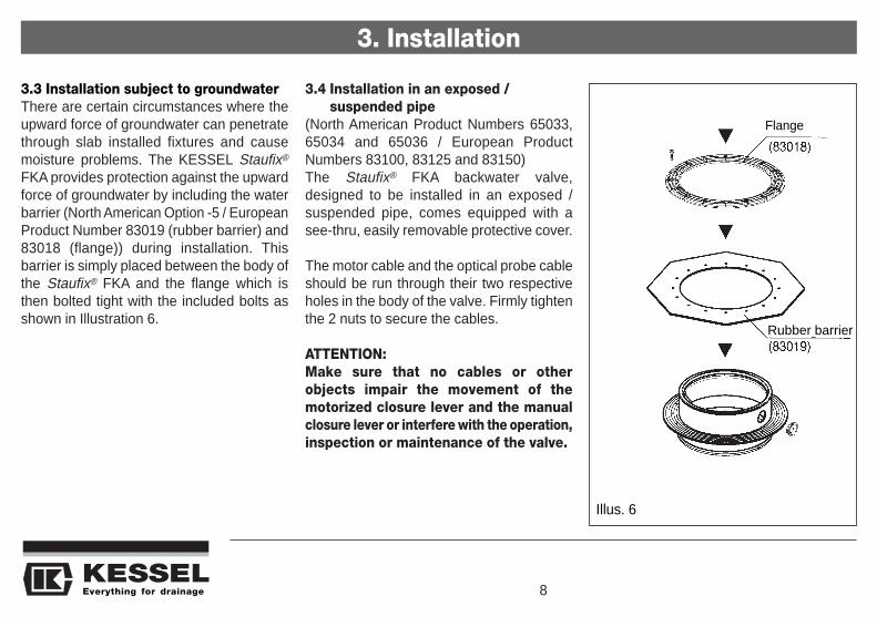
3.3 Installation subject to groundwaterThere are certain circumstances where theupward force of groundwater can penetratethrough slab installed fixtures and causemoisture problems. The KESSEL Staufix®
FKA provides protection against the upwardforce of groundwater by including the waterbarrier (North American Option -5 / EuropeanProduct Number 83019 (rubber barrier) and83018 (flange)) during installation. Thisbarrier is simply placed between the body ofthe Staufix® FKA and the flange which isthen bolted tight with the included bolts asshown in Illustration 6.
3.4 Installation in an exposed /suspended pipe
(North American Product Numbers 65033,65034 and 65036 / European ProductNumbers 83100, 83125 and 83150)The Staufix® FKA backwater valve,designed to be installed in an exposed /suspended pipe, comes equipped with asee-thru, easily removable protective cover.
The motor cable and the optical probe cableshould be run through their two respectiveholes in the body of the valve. Firmly tightenthe 2 nuts to secure the cables.
ATTENTION:Make sure that no cables or otherobjects impair the movement of themotorized closure lever and the manualclosure lever or interfere with the operation,inspection or maintenance of the valve.
Everything for drainage 8
Illus. 6
Flange
Rubber barrier

3. Installation
Everything for drainage9
3.5 Installation Example
a Staufix® FKAb Flangec Motorized backwater flapd Manual closure levere Motorf Control unitg Cover (Load capacility -
1.5 tons)
cm
Cellar drain, washing machines,sinks, bathtubs, toilets Power and
probe cables

4. Electrical connections
a Cover screws (x4)b Hinges (x2)c Connection diagram
d Mounting screws (x4)e Plastic wall plugs (x4)f 9 volt batteries (x2)
6
Illus. 7
4.2 Cable connections
An electrical connection plan is located onthe inside of the control unit cover.Open and pierce the two middle gaskets onthe bottom of the control panel (as seen inIllustration 8). Push the nut and hand boltonto each cable (as seen in Illustration 9).Insert the cable for the motor through the left
pierced gasket and the cable for the opticalprobe through the right pierced gasket andinto the control unit making sure to pull onlyenough cable into the control unit to makethe necessary connections. Secure the ca-bles to the control unit box (as seen in Illus.9) by tightening the plastic hand bolts.
Illus. 8
Everything for drainage 10
4.1 Wall mounting of the control unitAs always, make sure the control unit is disconnected from the power supply beforeopening the cover!Unscrew the four screws located in each corner of the front of the control unit and openthe cover. In each corner of the inside of the control unit will be four holes for mountingthe control unit to the wall (as seen in Illusration 7). Included with the control unit are 4
mounting screws,4 plastic wallplugs and adrilling templatewhich is printedon the cardboardcontrol unit box.
To connect the wires, firmly insert a smallscrewdriver into the upper opening of eachjack and push up (as seen in Illustration 10).This opens the terminal below. Insert thelead of the corresponding wire into the loweropening of the jack and release thescrewdriver. This will connect the wire. Nowconnect the wires of the motor and theoptical probe to their respective terminals(as seen in Illustration 10). The three wiresfor the motor are labelled ‘1’, ‘2’ and ‘3’ andshould be connected to the correspondingnumbered wire jacks on the jacks marked‘MOTOR’. The three wires for the opticalprobe are also labelled ‘1’, ‘2’ and ‘3’ and
should be connected to the correspondingnumbered wire jacks on the jacks marked‘SONDE’.
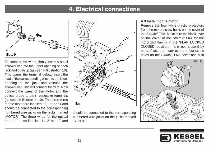
4.3 Installing the motorRemove the four white plastic protectorsfrom the motor screw holes on the cover ofthe Staufix® FKA. Make sure the black leveron the cover of the Staufix® FKA for themotorized flap is in the ‘FLAP LOCKEDCLOSED’ position. If it is not, close it byhand. Place the motor over the four screwholes on the Staufix® FKA cover and also
4. Electrical connections
Everything for drainage11
Illus. 9
Illus.
Illus. 11

make sure that the drive shaft of the motorfits into the drive shaft slot on the black lever(as seen in Illustration 11). Secure the motorfirmly with the four included screws.
4.4 Installing the optical probeTo install the optical probe into the Staufix®
FKA simply remove the small purple plugfrom the cover of the Staufix® FKA byunscrewing the two screws. Now insert theprobe and tighten with the same two screws
(as seen in Illustration 12). The opticalprobe is designed so that it can only be in-stalled the proper way.
4.5 Audible signalling device withextension cable
An optional audible signalling device withextension cable (North American Option -6/ European Product Number 20162) can beconnected if it is required that the audiblewarning signal be located in other areas ofthe building.
4.6 Signalling device with auxiliaryconnection
An optional additional circuit board with anauxiliary connection (North American Option-7 / European Product Number 80072) canbe installed to allow the Staufix® FKA to beconnected to a warning beacon, audiblealarm or a building’s central control system.The additional circuit board is plugged intothe mother board inside the control unit andfastened with the 4 provided screws (asseen in Illustration 13).
4.7 Shortening the cablesThe cables from the control unit to theStaufix® FKAcan be shortened if necessary.However, please insure that there isalways enough cable so that the Staufix®
FKA motor and cover can be removed forinspection and maintenance.
NOTE: VDE 0100, VDE 01107, IECguidelines or regulations issued by localpower companies must always befollowed. Also, the control unit must notbe installed in areas where there is anexplosion risk.
4. Electrical connections
Illus. 13
Illus. 12
Everything for drainage 12

Everything for drainage13
5. Initializing the system
While the control unit is unplugged connectthe two supplied 9-volt batteries which arealready located inside the control unit.Close the cover of the control unit and tigh-ten the four screws. Plug in the control unitto a proper power supply. The control unitwill perform a basic systems check. This isindicated by the ‘CLOSED / TEST FLAP’light which will begin to blink about 15 se-conds after either the two batteries areconnected or the control unit is plugged in.D u r i n ginitialization the system checks the
batteries, the optical probe and the motorconnections to confirm that they areproperly connected and in working order. Itwill also perform a flap closure check byclosing and opening the motorized flap ifinitially in the open position or by openingthe motorized flap if initially in the closedposition.If the entire system has been installedcorrectly the green ‘POWER’ LED on thecontrol unit will turn on and remain on. TheStaufix® FKA is now ready for operation.When the system is ready for
operation, make sure that the red manualclosure lever for the backwater flap is in the‘FLAP OPEN (FREE HANGING)’ or the‘FLAP OPEN (OUT OF FLOW)’ position. Ifit is not, open it with the red manual closurelever. Also make sure that the the motorizedflap is in the ‘FLAP OPEN (OUT OF FLOW)’position. If it is not press the ‘CLOSED /TEST FLAP’ button which will open the mo-torized flap.To check if the system isfunctioning properly, perform the steps inChapter 10.3 and 10.4.

6. Operation
6.1 Examples of operation
Power OperationLED LED Color Battery Operation
Everything for drainage 14
System Functioning POWER green On OffALARM orange Off flashesBACKWATER red Off OffCLOSED /TEST FLAP orange Off Off
Flap closing - backwater POWER green On OffALARM orange On OffBACKWATER red flashes OffCLOSED /TEST FLAP orange flashes flashes
Flap closed - backwater POWER green On OffALARM orange On OffBACKWATER red flashes OffCLOSED /TEST FLAP orange On OffAUDIBLE ALARM beeping (fast) beeping (2 seconds)

Everything for drainage15
6. Operation
6.2 Control unit function buttons
‘ALARM’ buttonThe audible alarm can be acknowledgedand turned off by pressing the ‘ALARM’button. This will also turn off the ‘ALARM’LED. The audible alarm is only re-activatedthe next time backwater occurs.
‘CLOSED / TEST FLAP’ buttonThis test button is used to operate themotorized backwater flap for maintenanceor testing purposes. The flap can be closedby pressing the button and opened by pres-sing the button again. The ‘CLOSED / TESTFLAP’ LED will blink as the motorized flap isclosing or opening and remain on once theflap is closed. An audible alarm will alsosound once the flap has been closed by
means of the button. A different audiblealarm sounds when the flap has closedbecause of backwater.
Please note that if the motorized flap isclosed using the ‘CLOSED / TEST FLAP’button, it will not reopen automatically. Thebutton must be pressed again to open themotorized flap. It is important to alwayscheck that the motorized flap is in the ‘FLAPOPEN (OUT OF FLOW)’ position aftermaintenance or testing has been completed.
In order to conserve battery power, theStaufix® FKA will not allow the user to closethe motorized flap for maintenance or testingpurposes while it is in battery back-up mode.Only the presence of backwater will closethe motorized flap while the Staufix® FKA is
in battery backup mode. During batterybackup, backflow is displayed by an audible‘beep’. No LEDs are lit.

If problems occur during initialization and operation, the Staufix FKA’s control unit will detect, diagnose and display the problem using theLEDs and audible alarms from the control unit.7.1 Problems during power operation:
Everything for drainage 16
7. Problem notification
Notification Problem Solution Tips
‘POWER’ LEDblinks andaudible alarmssounds
All four LEDs blinksimultaneously andaudible alarmsounds.
The upper two LEDs(‘POWER’ and ‘ALARM’)and the lower two LEDs(‘BACKWATER’ and‘CLOSED / TEST FLAP’)blink alternatingly andaudible alarm sounds.
9 volt batteries in control unitnot connected or low onpower. Batteries missing orfaulty.
During initialization, motorcables not properly connec-ted, polarity reversed ormotor is damaged. Duringoperation, motor controlleads faulty.
During initialization, opticalprobe cables not properlyconnected, polarity reversedor optical probe is damaged.During operation, opticalprobe leads faulty.
Disconnect Staufix® FKA from power sour-ce, connect or replace batteries (Pleasedispose of old batteries properly). Closethe cover and tighten the cover screws ofthe control unit and then plug in controlunit.
Disconnect Staufix® FKA from power source, di-sconnect 9 volt batteries in control unit. Inspectthe motor and all cables to make sure they arein working order and properly installed. Repla-ce motor if necessary. Reconnect batteries,close the cover and tighten the cover screws ofthe control unit and then plug in control unit.
Disconnect Staufix® FKA from power source,disconnect 9 volt batteries in control unit.Inspect the optical probe and all cables or installnew optical probe if necessary. Reconnect batte-ries, close the cover and tighten the cover screwsof the control unit and then plug in control unit.
If the batteries have not been connected,the system will have to be re-initialized.Disconnect the Staufix® FKA from itspower source, wait 10 seconds, connectthe two 9-volt batteries and plug theStaufix® FKA back in for re-initialization.
Install motor and cables carefully toprevent incorrect connections andpolarity problems.
The optical probe and its connec-tions are checked by the control unitevery 2 seconds.

Everything for drainage17
7. Problem notification
Notification Problem Solution Tips‘POWER’ and‘ALARM’ LEDs areon, the ‘CLOSED /TEST FLAP’ LEDblinks and audiblealarm sounds.
‘POWER’ and‘ALARM’ LEDs areon, ‘BACKWATER’and ‘CLOSED /TEST FLAP’ LEDsblink alternatinglyand audible alarmsounds
Motorized flap cannot closecompletely during initializationor testing. In this case themotorized flap is beingobstructed by an object.
Motorized flap cannot closecompletely during times ofbackwater. In this case themotorized flap is beingobstructed by an object.
Disconnect Staufix® FKA frompower source, disconnect 9 voltbatteries in control unit. Removethe cover of the Staufix® FKA,remove the obstruction.Reconnect batteries, close thecover and tighten the coverscrews of the control unit andthen plug in control unit.
Close manual closure lever toprotect against backwater. Waitfor backwater to subside thendisconnect Staufix® FKA frompower source, disconnect 9 voltbatteries in control unit. Removethe cover of the Staufix® FKA,remove the obstruction.Reconnect batteries, close thecover and tighten the coverscrews of the control unit andthen plug in control unit.
When the motorized flap cannot closecompletely due to an obstruction, the controlunit makes three attempts to close the motorizedflap in an attempt to dislodge the obstruction.If it succeeds in dislodging the object, theStaufix® FKAreturns to normal operation. If theobstruction remains in place an alarm willsound to notify the user of the blockage whichcould subject the building to backwater risk.Pressing the ‘ALARM’ button will not turn offthe audible alarm. The audible alarm continuesto sound to make sure that the user realizesthat the blockage must be removed. Pressingthe ‘CLOSED / TEST FLAP’ button will re-openthe flap and stop the audible alarm. It is nowimportant to disconnect the Staufix® FKA fromthe power source and to disconnect 9 voltbatteries in control unit. Remove the cover ofthe Staufix® FKA, remove the obstruction andre-start the system.

7. Problem notification
7.2 Problems during battery operation / power outages
Notification Problem Solution Tips‘ALARM’ LED blinks everytwo seconds.
All LEDs blinksimultaneously every 2seconds and audiblealarm sounds.
The upper two LEDs(‘POWER’ and ‘ALARM’) andthe lower two LEDs(‘BACKWATER’ and‘CLOSED / TEST FLAP’)blink alternatingly every twoseconds and audible alarmsounds.
Staufix® FKA is in batteryback up mode (notreceiving outlet power).
During initialization,motor cables not properlyconnected, polarity reversedor motor is damaged.During operation, motorcontrol leads faulty.
During initialization,optical probe cables notproperly connected,polarity reversed oroptical probe is damaged.During operation, opticalprobe leads faulty.
Check power source and restore mainpower if possible.
Disconnect Staufix® FKA from powersource, disconnect 9 volt batteries incontrol unit. Inspect the motor and allcables. Install new motor if necessary.Reconnect batteries, close the coverand tighten the cover screws of thecontrol unit and then plug in control unit.
Disconnect Staufix® FKA from powersource, disconnect 9 volt batteries incontrol unit. Inspect the optical probeand all cables. Install new optical probeif necessary. Reconnect batteries,close the cover and tighten the coverscrews of the control unit and then plugin control unit.
The Staufix® FKA will remain opera-tional for approximately 10 hours onbattery back up. After this time periodthe Staufix® FKA will go into ‘sleepmode’ (see Chapter 7.2, AdditionalFunctions).During battery operation, motorproblems are only detected whilethe motorized flap is in operation.
The optical probe and its connec-tions are checked by the control unitevery 60 seconds.
Everything for drainage 18

7. Problem notification
Notification Problem Solution Tips‘CLOSED / TESTFLAP’ LED blinksevery 2 secondsand audible alarmsounds (motorizedflap in the ‘open’position).
‘CLOSED / TESTFLAP’ LED blinksevery 2 secondsand audible alarmsounds (motorizedflap in the ‘closed’position or between‘open’ and ‘closed’).
Motorized flap cannotclose completely duringinitialization or testing. Inthis case the motorizedflap is being obstructedby an object.
Motorized flap cannotclose completely duringtimes of backwater due toan obstruction.
Disconnect Staufix® FKA frompower source, disconnect 9 voltbatteries in control unit. Removethe cover of the Staufix® FKA, re-move the obstruction. Reconnectbatteries, close the cover and tigh-ten the cover screws of the controlunit and then plug in control unit.
Close manual closure lever. Wait forbackwater to subside thendisconnect Staufix® FKA from powersource, disconnect 9 volt batteries incontrol unit. Remove the cover of theStaufix® FKA, remove the obstruc-tion. Close the cover and tighten thecover screws of the control unit andthen plug in control unit. Make sureto reopen the manual closure leverafter backwater has subsided.
When the motorized flap cannot closecompletely due to an obstruction, the controlunit makes three attempts to close the motorizedflap in an attempt to dislodge the obstruction.If it succeeds in dislodging the object, theStaufix® FKAreturns to normal operation. If theobstruction remains in place an alarm willsound to notify the user of the blockage whichcould subject the building to backwater risk.Pressing the ‘ALARM’ button will not turn offthe audible alarm. The audible alarm continuesto sound to make sure that the user realizesthat the blockage must be removed. Shut themanual closure lever and wait for the backwa-ter to subside. Disconnect Staufix® FKA fromthe power source and disconnect 9 volt batte-ries in control unit. Remove the cover of theStaufix® FKA, remove the obstruction and re-start the system.
Everything for drainage19

8. Additional Functions
8.1 Self Diagnosis System (SDS)The Staufix® FKA control unit is equippedwith SDS. This system automatically teststhe motor and the motorized flap once everyweek. During this test the motorized flap willclose once, check to see that it can make acomplete water tight seal and then re-open.If faults or an obstruction in the valve isdetected during this test, the problems willbe indicated on the control unit and can becorrected by following the instructions inChapter 7.
8.2 Sleep modeThe Staufix® FKA can operate on batterybackup power for approximately 10 hoursafter which it will automatically go into sleepmode. This is a backwater protectionprecaution when outlet power is no longeravailable and battery power is low. When theStaufix® FKA goes into sleep mode it willshut the motorized flap until power is restoredto the unit. During this time there will be noaudible or visual warnings unless thesystem is equipped with the signalling devicewith auxiliary connection in which case thissystem will still receive a signal. Whenpower is returned to the Staufix® FKA it willreturn to normal operation.
8.3 Battery life and replacementWhile the Staufix® FKA is connected to asuitable power supply, the unit continuouslychecks the condition of the two batteries. Ifat time of initialization the batteries holdunder 12.5 Volts total power, the Staufix®
FKA will not initialize itself. In this case,unplug the Staufix® FKA control unit from itspower source, check and replace thebatteries if necessary and then reconnectthe control unit to its power source. Theestimated life of new batteries is four years.Batteries certified for use with the KESSELStaufix® FKA are Duracell 9 Volt Type MN1604/6LR61 (Requirement - 2). If discardingbatteries, please do so properly.
Everything for drainage 20

9. Technical Data for control unit
Voltage 120 Volt AC (USA model) / 230 Volt AC (European Model)
Frequency 60 Hz (USA model) / 50 Hz (European Model)
Signalling device with auxiliary connection 42 Volt DC / 0.5 A
Operating temperature range 32 deg F - 104 def F (0°C - 40°C)
Splash protection rating IP 54 (Splash proof)
Motor cable check cycle Checked each time motor is operated
Optical probe cable check cycle Continuously during power operation / Every 60 sec during battery operation
Optical probe check cycle Continuously during power operation / Every 2 sec during battery operation
Battery condition check cycle Every 300 sec
Motor closing time 30 seconds
Everything for drainage21

10. Inspection and Maintenance
10.1 InspectionThe Staufix® FKA should be inspected everymonth by the operator or a person authorizedto do so. The control unit and valve should bevisually inspected and the motorized flapshould be closed and re-opened by pressingthe ‘CLOSED / TEST FLAP’ button on thecontrol unit. The manual flap closure levershould also be closed and opened by handseveral times to make sure that it is in properworking order. When the monthly inspectionis completed, make sure that both themotorized and manual backwater flaps areboth in the open position so that wastewatercan drain normally through the valve.
10.2 MaintenanceThe Staufix® FKAmust be inspected every sixmonths by a licensed professional servicer asshown in Illus. 15 - 19. It is important not todrain any plumbing fixtures connected to theStaufix® FKA during this inspection and alsonot to perform this inspection during times ofpotential backwater (heavy rain / flooding).
Illus. 15 Illus. 16 Illus. 17
Apply grease to allseals and to curvedinterior of motorizedflap grip.
a) Close the motorized flap usingthe ‘CLOSED / TEST FLAP’ buttonand also close the manual flapby hand using the manual flapclosure lever.
b) Unscrew the six nuts on thecover of the valve
c) Remove the cover being carefulnot to pull on the cables connectedto the control unit
a) Remove both backwater flapsalong with their housings
b) Clean all partsc) Check condition of all rubber
seals
a) Apply grease to the rubber sealon the outside of both of thesupport brackets and also applygrease in the body of the valvewhere the support brackets areseated
b) Replace both backwater flapsalong with their supportbrackets in their appropriateslots
c) Replace the cover. Retightenthe six bolts in a crosswise pat-tern to a torque of 6 lbf-ft (8Nm).
d) Now carry out a operational andoptical probe check as describedin section 10.3 and 10.4
Everything for drainage 22

10. Inspection and Maintenance
10.3 Operational Check(According to DIN 19578)(Please see Illustration 18)
Close the motorized flap (#7) using the‘CLOSED / TEST FLAP’ button and alsoclose the manual flap by hand using themanual flap closure lever (#6). Remove the1/2 inch plug (#1) from the cover of theStaufix® FKAwith a large screwdriver and byhand screw on the funnel (#2) with itsextension if available (#3, not included).Now pour water into the funnel until a levelof 100 cm (1 meter) is reached. Over thenext ten minutes observe the water level inthe funnel and refill if necessary keepingtrack of how much water is needed to keepthe water level constant. If after ten minutesthe amount of water needed to keep thewater level constant at 100 cm is less than500 cubic centimeters (1/2 liter, approx 1/2quart), the backwater valve is considered tobe water tight. This is a performance test
used by the German Industry Norm. Afterthe test, remove the calibration funnel andextension tube by hand and with a largescrewdriver firmly replace the plastic plug.Re-open the manual closure lever by handto the ‘open’ (vertical) position and re-openthe motorized flap by pressing the ‘CLOSED/ TEST FLAP’ button on the control unit.
10.4 Testing the optical probe(Please see Illustration 19)Unscrew the two screws on the optical probe andremove the optical probe. Immerse the lens of theoptical probe in a glass of water. The motorized flapshould begin to close as well as the visual andaudible alarms sounding once the motorized flap isfully closed. As soon as the optical probe is removedfrom the water, the motorized flap should re-openand the visual and audible alarms should stop. If theoptical lens is dirty it should be cleaned with a cleansoft cloth or tissue. When finished, re-insert theoptical probe and tighten the two screws.
Illus. 18
Illus. 19
Everything for drainage23
TE
ST
FU
NN
EL

11. Replacement Parts
Description Order NumberFKA Motor (limited submersibility) (IP 68) 80075
Signalling device with auxiliary connection 80072 (Option -7 / USA)
Audible signalling device with extension cable (33 feet) 20161
Audible signalling device with extension cable (66 feet) 20162 (Option -6 / USA)
FKA cover with manual closure lever 80026
FKA motorized flap with large rubber seal 80031
FKA motorized flap housing with large rubber seal 80032
Manual closure backwater flap with housing 80036
Test funnel 70214
Seal for FKA cover with manual closure lever 70202
Inner large seal for motorized flap 70230
Outer thin seal for motorized flap housing 70240
Outer seal for manual closure backwater flap housing 70157
Seal for manual closure backwater flap (flat seal) 70156
9 Volt battery (x1) 197-081
Everything for drainage 24

12. Warranty
This product is warranteed to be free ofdefects in material and workmanship. Thiswarranty is for a period of six (6) months andbegins with the date of purchase. Thiswarranty is only valid on material andworkmanship that upon the manufacturer’s
inspection is deemed to be the fault of themanufacturer. Warranty claims shall besubmitted to the manufacturer in writing. Incases where the manufacturer is found to beat fault, the manufacturer shall have theoption of repairing or replacing the defective
item. The manufacturer shall not beresponsible for any labor or shippingcharges or any loss, injury or damageswhatsoever, including incidental orconsequential damages.
Everything for drainage25

Everything for drainage 26
Notes

Everything for drainage27
Notes

Everything for drainage
Solutions from a single sourceEverything for Drainage
Backwater valves and cleanouts
Polymer and cast iron drains
Volatile liquid traps
Lifting stations, pumps, warningand control units
Rainwater management systems
Grease, starch and oil / fuelseparators
Inspection chambers
Custom projects for industrialapplications
Polymer pipe fittings
Stainless steel drains andchannels