installation manual a1140 three-phase meter wc or ct & ldc · version 3 issue date: 01/02/2019...
TRANSCRIPT
MAN28Version 3
Issue Date: 01/02/2019
Installation manual
A1140 three-phase meter WC or CT
& LDC
MAN28Version 3
Issue Date: 01/02/2019
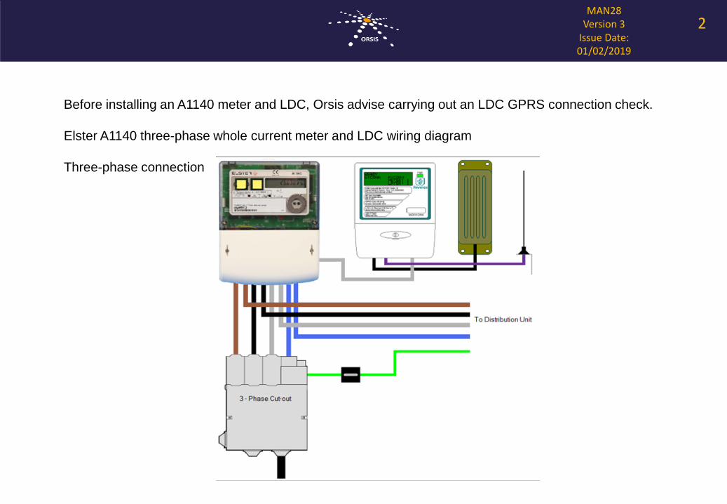
Before installing an A1140 meter and LDC, Orsis advise carrying out an LDC GPRS connection check.
Elster A1140 three-phase whole current meter and LDC wiring diagram
Three-phase connection
2
MAN28Version 3
Issue Date: 01/02/2019
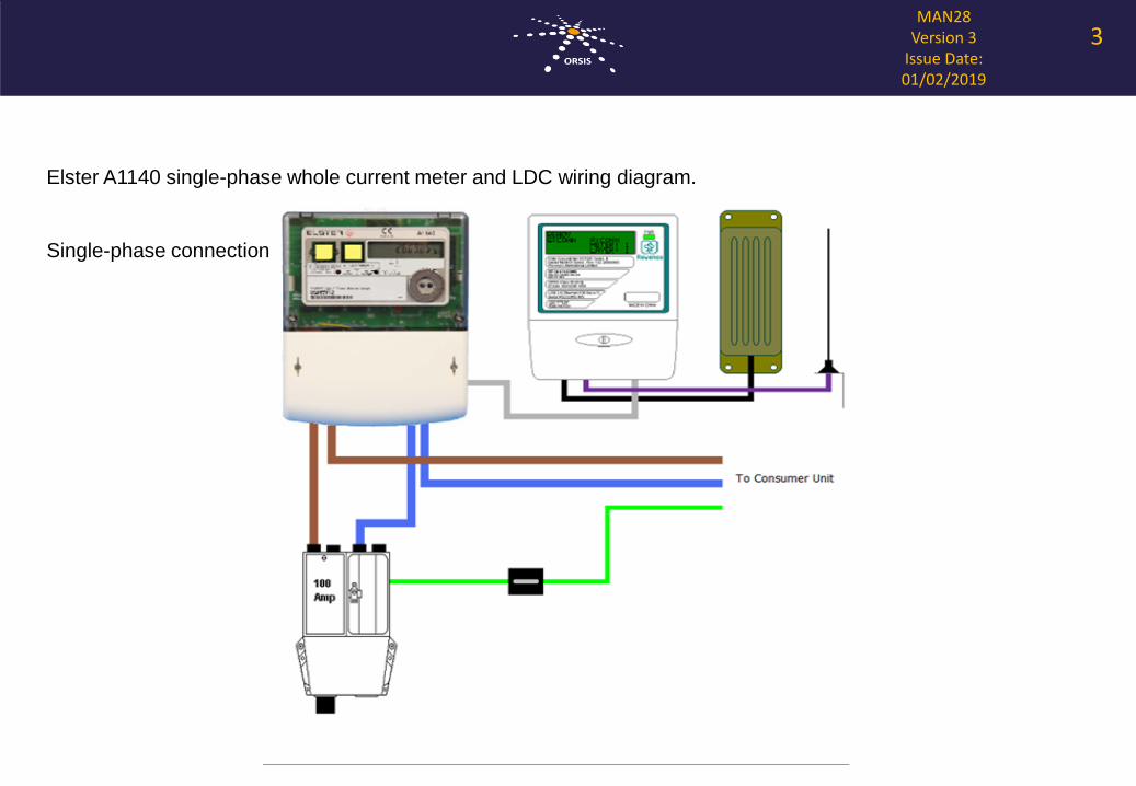
Elster A1140 single-phase whole current meter and LDC wiring diagram.
Single-phase connection
3
MAN28Version 3
Issue Date: 01/02/2019
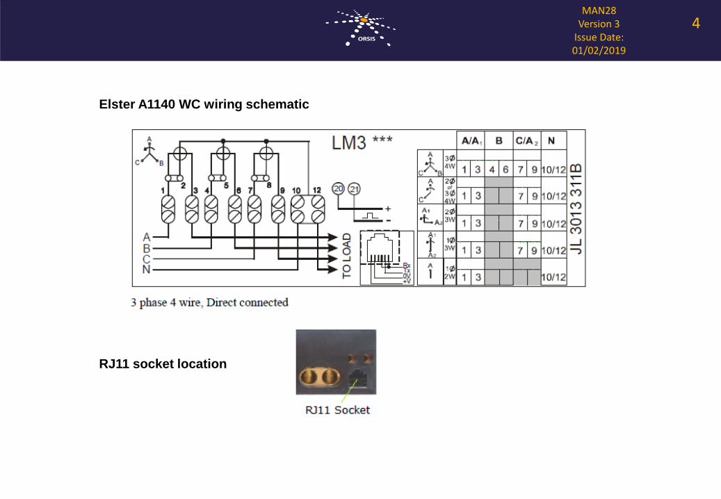
Elster A1140 WC wiring schematic
RJ11 socket location
4
MAN28Version 3
Issue Date: 01/02/2019
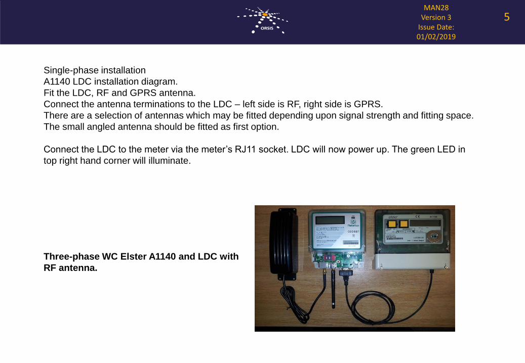
Single-phase installation
A1140 LDC installation diagram.
Fit the LDC, RF and GPRS antenna.
Connect the antenna terminations to the LDC – left side is RF, right side is GPRS.
There are a selection of antennas which may be fitted depending upon signal strength and fitting space.
The small angled antenna should be fitted as first option.
Connect the LDC to the meter via the meter’s RJ11 socket. LDC will now power up. The green LED in
top right hand corner will illuminate.
5
Three-phase WC Elster A1140 and LDC with
RF antenna.
MAN28Version 3
Issue Date: 01/02/2019
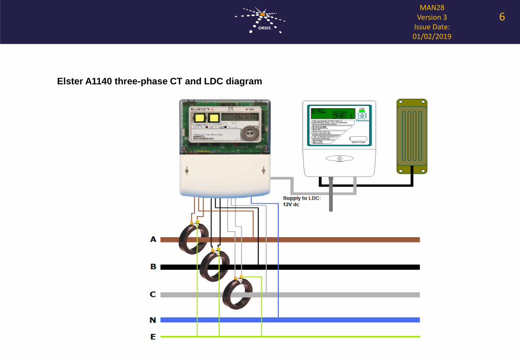
Elster A1140 three-phase CT and LDC diagram
6
MAN28Version 3
Issue Date: 01/02/2019
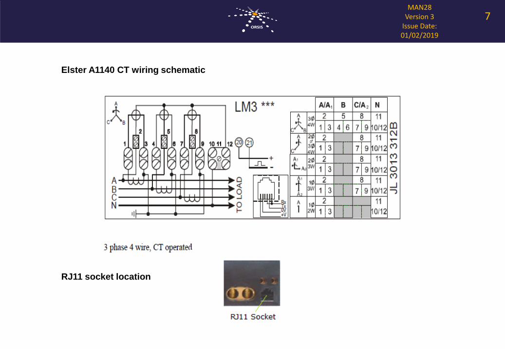
Elster A1140 CT wiring schematic
7
RJ11 socket location
MAN28Version 3
Issue Date: 01/02/2019
UNDER NO CIRCUMSTANCES MAY THE SECONDARY CIRCUIT OF A CT BE OPENED WHEN
CURRENT IS FLOWING IN THE PRIMARY CIRCUIT.
The voltage in an un-terminated secondary winding can reach several thousand volts in a
fraction of a second if it is made open-circuit while current is flowing in the primary circuit being
metered. Such high voltages can be extremely dangerous to personnel and can cause serious
damage to the transformer or equipment connected to it. Such damage may not be immediately
obvious, but will certainly lead to incorrect operation of the equipment.
POLARITY
CTs are direction sensitive and must be fitted the correct way round. CTs are marked with P1 and
P2 to indicate which way they should be fitted around the cable or bus-bar. The side marked P1
must point towards the supply, and P2 must point towards the load. If an arrow is printed on the
CT it must point towards the load.
The CT outputs - “secondary’s” - must be connected to the meter the correct way round. CTs are
supplied with secondary terminals marked S1 and S2 which must be connected to the correct
terminals on the meter. The meter will not register correctly if any of the CTs are connected
incorrectly.
The CTs must be connected to the correct phase inputs on the meter.
8
MAN28Version 3
Issue Date: 01/02/2019
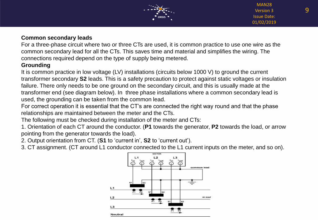
Common secondary leads
For a three-phase circuit where two or three CTs are used, it is common practice to use one wire as the
common secondary lead for all the CTs. This saves time and material and simplifies the wiring. The
connections required depend on the type of supply being metered.
Grounding
It is common practice in low voltage (LV) installations (circuits below 1000 V) to ground the current
transformer secondary S2 leads. This is a safety precaution to protect against static voltages or insulation
failure. There only needs to be one ground on the secondary circuit, and this is usually made at the
transformer end (see diagram below). In three phase installations where a common secondary lead is
used, the grounding can be taken from the common lead.
For correct operation it is essential that the CT’s are connected the right way round and that the phase
relationships are maintained between the meter and the CTs.
The following must be checked during installation of the meter and CTs:
1. Orientation of each CT around the conductor. (P1 towards the generator, P2 towards the load, or arrow
pointing from the generator towards the load).
2. Output orientation from CT. (S1 to ‘current in’, S2 to ‘current out’).
3. CT assignment. (CT around L1 conductor connected to the L1 current inputs on the meter, and so on).
9
MAN28Version 3
Issue Date: 01/02/2019
Using A1140 for PV export metering
Guidelines for wiring electricity meters for import and export metering
These are helpful guidelines for meter installers to assist with the wiring setup for generation and
import/export metering. Where Orsis have supplied meters and meter reading services, it is the
responsibility of the meter installer to ensure the installation, maintenance and security of the meter is dealt
with safely and properly.
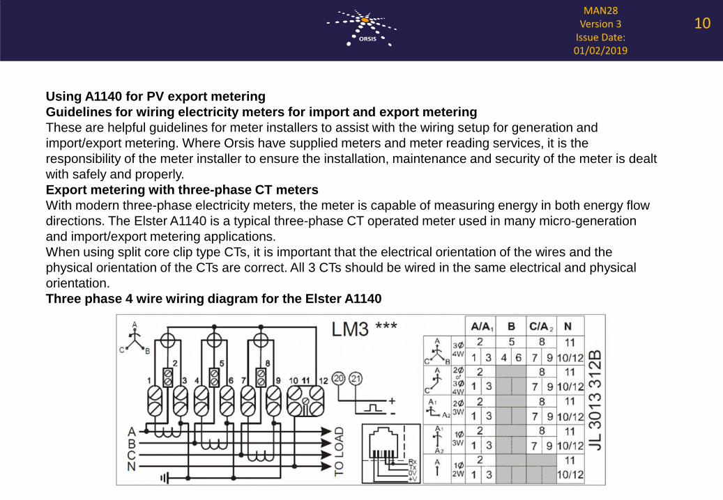
Export metering with three-phase CT meters
With modern three-phase electricity meters, the meter is capable of measuring energy in both energy flow
directions. The Elster A1140 is a typical three-phase CT operated meter used in many micro-generation
and import/export metering applications.
When using split core clip type CTs, it is important that the electrical orientation of the wires and the
physical orientation of the CTs are correct. All 3 CTs should be wired in the same electrical and physical
orientation.
Three phase 4 wire wiring diagram for the Elster A1140
10
MAN28Version 3
Issue Date: 01/02/2019
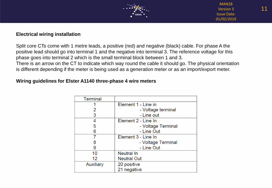
Electrical wiring installation
Split core CTs come with 1 metre leads, a positive (red) and negative (black) cable. For phase A the
positive lead should go into terminal 1 and the negative into terminal 3. The reference voltage for this
phase goes into terminal 2 which is the small terminal block between 1 and 3.
There is an arrow on the CT to indicate which way round the cable it should go. The physical orientation
is different depending if the meter is being used as a generation meter or as an import/export meter.
Wiring guidelines for Elster A1140 three-phase 4 wire meters
11
MAN28Version 3
Issue Date: 01/02/2019
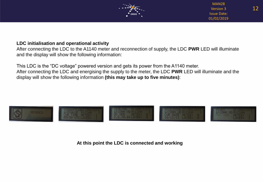
LDC initialisation and operational activity
After connecting the LDC to the A1140 meter and reconnection of supply, the LDC PWR LED will illuminate
and the display will show the following information:
This LDC is the “DC voltage” powered version and gets its power from the A1140 meter.
After connecting the LDC and energising the supply to the meter, the LDC PWR LED will illuminate and the
display will show the following information (this may take up to five minutes):
At this point the LDC is connected and working
12
MAN28Version 3
Issue Date: 01/02/2019
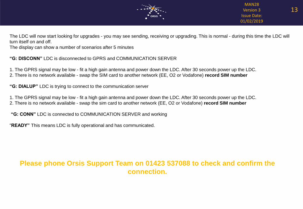
The LDC will now start looking for upgrades - you may see sending, receiving or upgrading. This is normal - during this time the LDC will
turn itself on and off.
The display can show a number of scenarios after 5 minutes
“G: DISCONN” LDC is disconnected to GPRS and COMMUNICATION SERVER
1. The GPRS signal may be low - fit a high gain antenna and power down the LDC. After 30 seconds power up the LDC.
2. There is no network available - swap the SIM card to another network (EE, O2 or Vodafone) record SIM number
“G: DIALUP” LDC is trying to connect to the communication server
1. The GPRS signal may be low - fit a high gain antenna and power down the LDC. After 30 seconds power up the LDC.
2. There is no network available - swap the sim card to another network (EE, O2 or Vodafone) record SIM number
“G: CONN” LDC is connected to COMMUNICATION SERVER and working
“READY” This means LDC is fully operational and has communicated.
Please phone Orsis Support Team on 01423 537088 to check and confirm the
connection.
13
MAN28Version 3
Issue Date: 01/02/2019
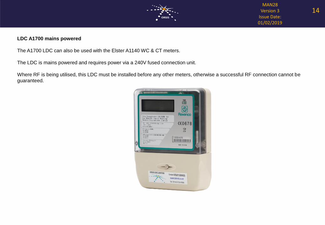
LDC A1700 mains powered
The A1700 LDC can also be used with the Elster A1140 WC & CT meters.
The LDC is mains powered and requires power via a 240V fused connection unit.
Where RF is being utilised, this LDC must be installed before any other meters, otherwise a successful RF connection cannot be
guaranteed.
14
MAN28Version 3
Issue Date: 01/02/2019
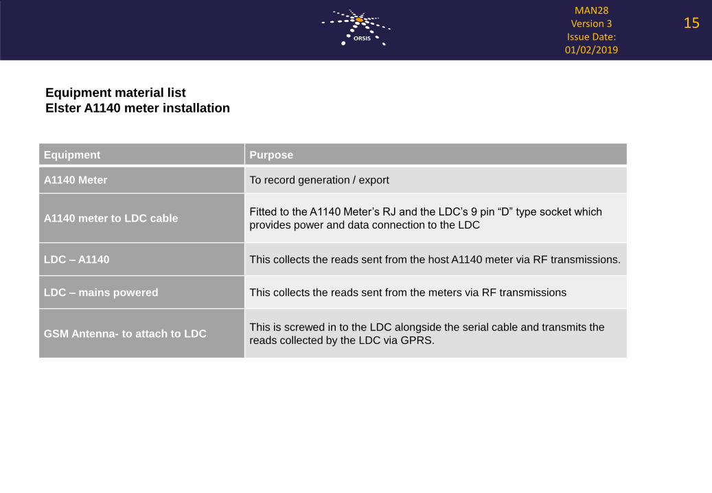
Equipment Purpose
A1140 Meter To record generation / export
A1140 meter to LDC cableFitted to the A1140 Meter’s RJ and the LDC’s 9 pin “D” type socket which
provides power and data connection to the LDC
LDC – A1140 This collects the reads sent from the host A1140 meter via RF transmissions.
LDC – mains powered This collects the reads sent from the meters via RF transmissions
GSM Antenna- to attach to LDCThis is screwed in to the LDC alongside the serial cable and transmits the
reads collected by the LDC via GPRS.
Equipment material list
Elster A1140 meter installation
15
MAN28Version 3
Issue Date: 01/02/2019
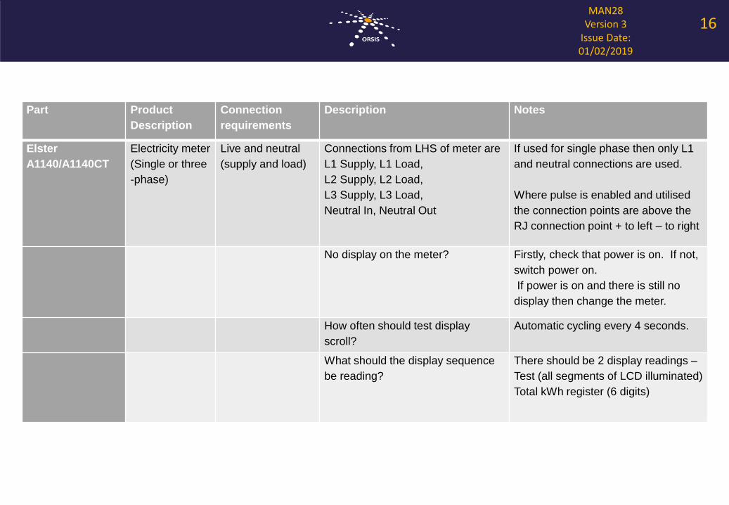
Part Product
Description
Connection
requirements
Description Notes
Elster
A1140/A1140CT
Electricity meter
(Single or three
-phase)
Live and neutral
(supply and load)
Connections from LHS of meter are
L1 Supply, L1 Load,
L2 Supply, L2 Load,
L3 Supply, L3 Load,
Neutral In, Neutral Out
If used for single phase then only L1
and neutral connections are used.
Where pulse is enabled and utilised
the connection points are above the
RJ connection point + to left – to right
No display on the meter? Firstly, check that power is on. If not,
switch power on.
If power is on and there is still no
display then change the meter.
How often should test display
scroll?
Automatic cycling every 4 seconds.
What should the display sequence
be reading?
There should be 2 display readings –
Test (all segments of LCD illuminated)
Total kWh register (6 digits)
16
MAN28Version 3
Issue Date: 01/02/2019
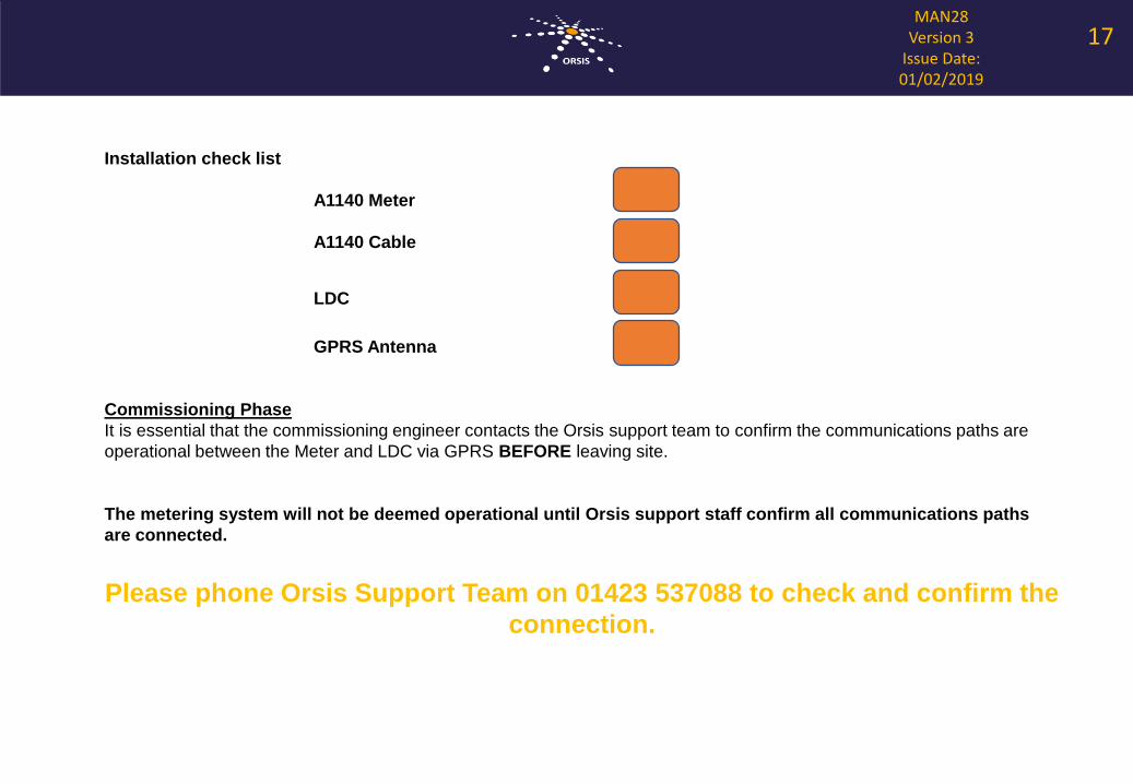
Installation check list
A1140 Meter
A1140 Cable
LDC
GPRS Antenna
Commissioning Phase
It is essential that the commissioning engineer contacts the Orsis support team to confirm the communications paths are
operational between the Meter and LDC via GPRS BEFORE leaving site.
The metering system will not be deemed operational until Orsis support staff confirm all communications paths
are connected.
Please phone Orsis Support Team on 01423 537088 to check and confirm the
connection.
17
MAN28Version 3
Issue Date: 01/02/2019
CT meter commissioning phase
For a CT installation it is essential that a full commissioning check is performed to confirm the meter is operating correctly. The
meter is sensitive to connections and L1, L2 and L3 must be connected in the correct order on the meter (from left to right).
The commissioning sheet on the following page (Appendix A) can be used to confirm correct meter operation.
The metering system will not be deemed operational until Orsis support staff confirm all communications paths are
connected.
Please phone Orsis Support Team on 01423 537088 to check and confirm the
connection.
18
MAN28Version 3
Issue Date: 01/02/2019
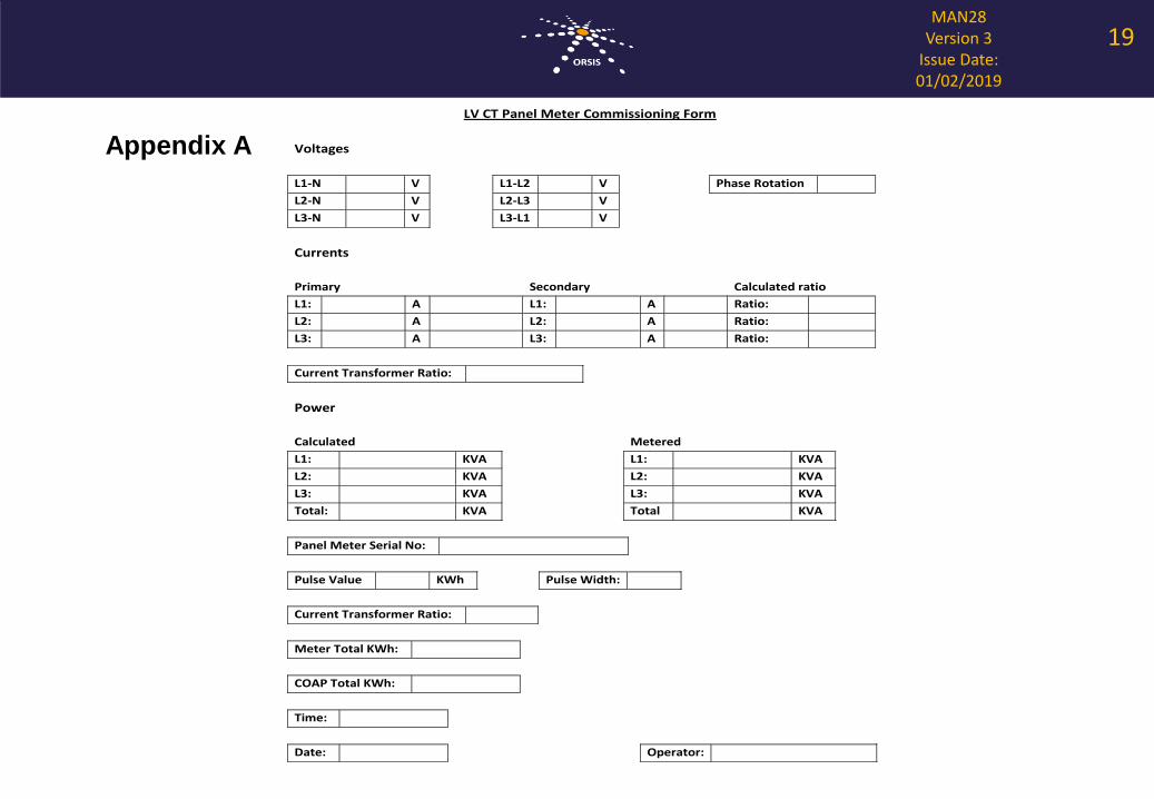
LV CT Metering Commissioning Form
FRM48
Version 1
Issue Date: 19.01.2012
Page 1 of 1
LV CT Panel Meter Commissioning Form
Voltages
L1-N V L1-L2 V Phase Rotation
L2-N V L2-L3 V
L3-N V L3-L1 V
Currents
Primary Secondary Calculated ratio
L1: A L1: A Ratio:
L2: A L2: A Ratio:
L3: A L3: A Ratio:
Current Transformer Ratio:
Power
Calculated Metered
L1: KVA L1: KVA
L2: KVA L2: KVA
L3: KVA L3: KVA
Total: KVA Total KVA
Panel Meter Serial No:
Pulse Value KWh Pulse Width:
Current Transformer Ratio:
Meter Total KWh:
COAP Total KWh:
Time:
Date: Operator:
Appendix A
19