installation, operation & maintenance manual -...
TRANSCRIPT

1 SCWIOMM0001.10
Installation, Operation & Maintenance Manual Standard Water Cooled Range

Installation Manual
2 SCWIOMM0001.10
This page is intentionally blank.

Installation Manual
3 SCWIOMM0001.10
Proprietary Notice This publication contains information proprietary and confidential to Smardt Chillers Pty Ltd trading as
PowerPax‐Smardt (hereafter referred to as PowerPax‐Smardt). Any reproduction, disclosure or
unauthorized use of this publication is expressly prohibited without written approval from PowerPax‐
Smardt. PowerPax‐Smardt reserves the right to make changes without notice in product or component
design as warranted by evolution in user needs or progress in engineering or manufacturing technology.
PowerPax‐Smardt has exercised its best efforts to ensure that the information contained in the manual is
correct. However, no warranty of reliability or accuracy is given with respect to the information and
PowerPax‐Smardt is not and shall not be responsible or liable for the correctness or suitability of the
information or for any error or omission.
All brand names and product names used in the manual are trademarks, registered trademarks, or trade
names of their respective holders.
© 2011, PowerPax & Smardt Chillers & Smardt Inc. All rights reserved.
For product support issues, corrections, or enquiries contact:
Product Support [email protected]
PowerPax‐Smardt
144 Colchester Road PO Box 2021
Bayswater North, Vic, 3153 Australia
+61 3 9761 5055www.powerpax.com.au
Smardt Chillers – Singapore
1 Maritime Square
11‐19A Harbourfront Centre
Singapore, 099253
+65 6273 1120

Installation Manual
4 SCWIOMM0001.10
Table of Contents
Installation, Operation & Maintenance Manual ....................................................................... 1
Proprietary Notice ....................................................................................................................... 3
List of Acronyms / Definitions .................................................................................................. 7
Installation ............................................................................................................................ 10
General ...................................................................................................................................... 10
Safety Precautions ..................................................................................................................... 10
Safety Guidelines ....................................................................................................................... 10
Warranty, Commissioning & Maintenance ............................................................................... 11
Spare Parts ................................................................................................................................. 11
Training ...................................................................................................................................... 11
General Description ................................................................................................................... 12
Customer Service ....................................................................................................................... 12
Heat Exchangers ........................................................................................................................ 13
Evaporator .............................................................................................................. 13
Water Cooled Condenser ....................................................................................... 13
Refrigeration Components ..................................................................................... 13
Controls ................................................................................................................... 13
Safeties .................................................................................................................... 14
Information on Welding ............................................................................................................ 14
Foundation ................................................................................................................................ 14
Clearance and Maintenance Access .......................................................................................... 14
Nameplates ............................................................................................................................... 15
Unpacking and Inspection ......................................................................................................... 16
Unit Placement .......................................................................................................................... 17
Rigging Requirements ................................................................................................................ 19
Dimensional Drawings ............................................................................................................... 20
Piping Configurations and Flow Connections ............................................................................ 32
Minimum Water Loop Volumes ................................................................................................ 33
Evaporator Water Circuits ......................................................................................................... 33
Flow Detection Devices ............................................................................................................. 33

Installation Manual
5 SCWIOMM0001.10
Relief Valves .............................................................................................................................. 34
Control Field Wiring ................................................................................................................... 34
Power Wiring ............................................................................................................................. 35
Disconnects and Power Wiring .................................................................................................. 36
Circuit Breakers ......................................................................................................................... 38
Line Reactor / RFI Filters ............................................................................................................ 38
Wiring Diagram & Schematic..................................................................................................... 38
Pre‐Commissioning .................................................................................................................... 39
Operation .............................................................................................................................. 44
System Checks Before Start Up ................................................................................................. 44
Powering up Compressors ......................................................................................................... 46
PowerPax‐Smardt Controller ................................................................................. 47
Inputs, Outputs, & Interlocks ................................................................................. 48
Head Pressure Control Option ............................................................................... 50
Summary of Status Contacts .................................................................................. 50
High Level Options .................................................................................................. 51
Operating the Controller ........................................................................................................... 52
Password Access ..................................................................................................... 52
Navigating the Controller ....................................................................................... 52
Data Entry ............................................................................................................... 52
Alarm Button ........................................................................................................... 52
Carel Controller User Level Screens .......................................................................................... 53
Front User Screen ................................................................................................... 53
Main Menu ............................................................................................................. 54
Operational Data .................................................................................................... 54
User Settings ........................................................................................................... 56
Compressor MB Data ............................................................................................. 57
Clock ........................................................................................................................ 58
History ..................................................................................................................... 59

Installation Manual
6 SCWIOMM0001.10
Information ............................................................................................................. 60
Maintenance ......................................................................................................................... 63
Water Cooled Maintenance Form ............................................................................................. 65
Appendix 1 – Recommended Spare Parts List ........................................................................... 71
Appendix 2 – Wiring Schematic ................................................................................................. 73

Installation Manual
7 SCWIOMM0001.10
List of Acronyms / Definitions
BACnet Proprietary High Level Protocol BMCC Bearing Motor Compressor Controller COM Communications (RS232) Serial Port EXV Electronic Expansion Valve HLI High Level InterfaceIGBT Insulated Gate Bipolar Transistor (Inverter) IGV Inlet Guide Vane I/O Board Compressor Interface Module LBV Load Balancing Valve LED Light Emitting DiodeModBus Proprietary High Level Protocol PCB Printed Circuit Board PCO3 Carel Controller with PowerPax‐Smardt Software PGD3 Color Touchscreen Display PWM Pulse Width Modulation – Bearing Amplifier RFI Radio Frequency Interference SCR Silicon Controlled Rectifier

Installation
8 SCWIOMM0001.10
This page is intentionally blank.

Installation
9 SCWIOMM0001.10
PowerPax‐Smardt Installation Manual

Installation
10 SCWIOMM0001.10
Installation
General This manual is intended to inform contractors, building owners, and engineers of the installation, commissioning,
operation, and maintenance requirements for the PowerPax‐Smardt air cooled centrifugal chiller range. It is
intended that this document be used alongside the applicable chiller general assembly drawing and wiring
diagrams, supplied with the chiller.
Prior to installation and set‐up of this chiller, it is intended that those involved in the installation, set‐up, operation
and maintenance of this chiller familiarize themselves with the procedures in this manual. This manual contains
the information necessary to become familiar with the controls system prior to working on this system.
Safety Precautions Access to the PowerPax‐Smardt chiller must be reserved for authorized personnel. Only those trained in maintenance and service are authorized to access the unit. Safety precautions must be observed during installation, start‐up and all service of the chiller due to the presence of high pressure refrigerant charge and high voltage hazards. Only qualified personnel should install, start‐up and service this equipment. Failure to use qualified personnel to work on PowerPax‐Smardt equipment will affect the equipment warranty and may result in serious injury. Always ensure that all required safety measures are followed such as:
Wearing protective clothing (gloves, shoes etc)
Wearing safety glasses
Wearing a grounding wrist strap
Using appropriate tools
Employing qualified electricians
Employing PowerPax‐Smardt trained and certified refrigeration technicians
Following local regulations and codes
Safety Guidelines Never cover or obstruct any safety device, including the relief valves in the refrigerant circuits. Ensure that all relief valves are vented outside the building/plant area in accordance with safety regulations. High concentration levels of refrigerant in enclosed spaces can displace oxygen and cause asphyxiation and lead to heart irregularities, unconsciousness, or death. Do not disable any safety devices.

Installation
11 SCWIOMM0001.10
WARNING!
High voltage electrical equipment is potentially lethal! Isolate incoming electrical power before attempting installation of the equipment. If work is interrupted, ensure that all circuits are de‐energized and power is still isolated before continuing work. Only a qualified electrician should work on high‐voltage electrical equipment.
Warranty, Commissioning & Maintenance Commissioning and maintenance of all PowerPax‐Smardt chillers is to be undertaken by PowerPax‐Smardt or a
PowerPax‐Smardt certified service provider. Failure to comply with this requirement will void the chiller warranty.
PowerPax‐Smardt chillers come with a unit parts and labour warranty in respect to all non‐consumable parts
(when installed within Australia, International warranty may vary), for a period of 12 months from the date of
commissioning or 18 months from the date of dispatch from PowerPax‐Smardt – whichever is sooner.
Warranty is not a substitute for maintenance. Warranty cover is conditional upon maintenance being carried out
according to the PowerPax‐Smardt recommendations during the warranty period. Failure to follow the designated
maintenance procedures and schedules will void the chiller warranty and remove any liability from PowerPax‐
Smardt. Please consult the PowerPax‐Smardt Terms and Conditions for a warranty statement.
Spare Parts PowerPax‐Smardt has a recommended spare parts list. Stocking the recommended spare parts can reduce service
response times. See Appendix 1 for the recommended spare parts list. For the recommended spare parts price list
please contact the PowerPax‐Smardt service department.
Training PowerPax‐Smardt offers a range of training courses on the complete range of PowerPax‐Smardt products. For
further information on the training courses available please see the PowerPax website (www.powerpax.com.au) or
contact PowerPax‐Smardt directly.
Wait a minimum of 15 minutes after isolating power before removing compressor access covers
as capacitors can store sufficient charge to cause electrocution within this time frame.

Installation
12 SCWIOMM0001.10
General Description PowerPax‐Smardt make a range of water cooled chillers from 200 to 3500kWr. The PowerPax‐Smardt water cooled
chiller range consists of Danfoss Turbocor centrifugal compressor(s), a flooded R134a shell and tube evaporator,
and a water cooled condenser. Liquid control is via a PowerPax‐Smardt Electronic Expansion Valve (EXV).
The compressors are semi‐hermetic, two stage, direct drive, variable speed centrifugals. This is a high speed
centrifugal machine which employs advanced magnetic bearing technology and direct drive to eliminate the need
for oil within the system.
Capacity control is provided by variable speed drive and inlet guide vanes, capable of reducing compressor
capacity to 25% of full load (at ARI550/590 standard part load conditions).
To accommodate loads below 25% there is a provision for discharge gas to be injected into the evaporator. This
provision is implemented by the controller only after the maximum turn down has been achieved by compressor
speed reduction. This ensures that the maximum efficiency is maintained at all times. This load balancing valve
feature can be disabled by the user through the chiller controller.
The compressor starts unloaded and current is limited to less than 2 amps per compressor. The maximum amps
are also limited to a preset value by the compressors inbuilt control software. Motor cooling is provided by an
integrated liquid refrigerant injection system controlled by the compressor. The compressor is equipped with
discharge and suction shutoff (isolating) valves, and fitted check valves to prevent reverse spin on shutdown.
Customer Service For additional product support please contact the PowerPax‐Smardt service department at: [email protected] or call +61 3 9761 5055. For additional sales support please contact the PowerPax sales department at: [email protected] or call +61 3 9761 7905. For additional product support, or Sales Support throughout Asia‐Pacific, please contact the Singapore Office at: [email protected] or call +65 6273 1120 Or visit the PowerPax website at: www.powerpax.com.au
As a guide, a number of units from 200 to 2800kWr at nominal conditions have been pre‐selected and used throughout the manual for information purposes only.
Please contact PowerPax with your specific requirements or specific technical data.

Installation
13 SCWIOMM0001.10
Heat Exchangers
Evaporator
The evaporator is a flooded shell and tube design using enhanced surface finned copper tubes. It is constructed in
accordance with ASME code for a refrigerant side working pressure of 1320kPa and is tested for a maximum
water‐side pressure of 1000 kPa.
The evaporator shell is insulated with 19mm closed‐cell foam (max k factor of 0.038W/mK) with a vapor barrier
skin as standard. Further insulation is available as an optional extra.
Water Cooled Condenser
The condenser is a flooded shell and tube design using enhanced surface copper tubes. It is constructed in
accordance with ASME code for a refrigerant side working pressure of 1320 kPa and is tested for a maximum
water‐side pressure of 1000 kPa.
Correct operating refrigerant level is maintained by a control feedback loop which uses a resistance type level
sensor. This control function is built into the chiller controller which maintains the levels in the heat exchangers by
modulating the position of a stepper motor driven EXV. Similarly, the hot gas injection is controlled by the chiller
controller via a stepper motor driven valve. The set points and control terms for these functions are set at
commissioning via the chiller controller interface.
Refrigeration Components
Refrigerant circuit components include pressure relief valves, combination discharge check and isolation valves, suction line valves, motor cooling line filter drier, liquid line, condenser level float chamber, sight glasses, electronic expansion and load balancing valves and motor cooling isolation valves. The refrigeration system does not contain oil.
Controls
The chiller controller utilizes a microprocessor based controller running on PowerPax‐Smardt proprietary software. It handles the basic functions of chilled water temperature control, and condenser head pressure control. The controller incorporates a function to trip the circuit breaker in the event of a compressor controls failure. The controls protect the chiller against freezing by monitoring for low leaving water temperature and loss of water flow (via the external interlocks). The controller also monitors the compressor status signal which indicates the state of various production functions built into the compressor controller. In‐built compressor control functions protect against high head pressure, low suction pressure, power supply faults (voltage and imbalance), excess power input, excess amps input, excess motor temperature, and excessive electronics temperature. The controller fitted to the PowerPax‐Smardt water cooled chiller is a PLC based device manufactured by Carel
utilizing imbedded control software written specifically by PowerPax‐Smardt for PowerPax‐Smardt chiller
applications. It utilizes a color touch screen interface and provides access to settings via a combination of touch
screen and button controls.
The various applications are selectable through user interface screens to the touch screen interface. The status of
the compressors and various systems parameters can be viewed on these screens as can the log of up to 20 past
alarm events. The program is stored in non‐volatile memory and can be upgraded in the field.

Installation
14 SCWIOMM0001.10
The compressor controller also ensures compressor operation is between the limits (eg. surge) of its operational envelope at all times.
Safeties
PowerPax‐Smardt water cooled units are equipped to provide the following protection:
Low chilled water temperature
Power supply errors
Compressor motor thermal or electrical overload
Phase loss
High pressure
Low pressure
Loss of chiller water flow via an interlock to an external flow switch
Loss of condenser water flow to an external flow switch
Information on Welding PowerPax‐Smardt vessels are either ASME or AS1210 certified. Please note that welding should never be performed on the vessels or tube sheets. Such a practice will void the ASME certification. Do not weld on any part of the chiller under any circumstances as current can travel through the chiller earth if the welder earth is not satisfactory, unnecessarily damaging chiller and/or compressor electronics and voiding the unit warranty.
Foundation Before installing the chiller set, ensure that the supporting floor meets the load bearing requirements. Consult the Dimensions and Weight Table on page 17 to determine the load bearing requirements. Four point supports must be installed, two at each end of the chiller. PowerPax‐Smardt is not responsible for the load bearing capacity of the floor.
Clearance and Maintenance Access Adequate clearance around the chiller set is essential to facilitate maintenance and service. Required minimum clearances are tabulated under “Water Cooled Chiller Clearances” on page 18, please ensure that adequate space for all installation and service operations is allowed. Check that the minimum clearance complies with all local electrical codes. Each compressor weighs approximately 140 kilograms. It is advised that sufficient access be provided for rigging equipment and also is allowed for a small trolley to easily be brought alongside the chiller, to allow for future service and maintenance needs.

Installation
15 SCWIOMM0001.10
Nameplates
Nameplates are located in various locations on the chiller.
The chiller unit nameplate is located inside the control
cabinet door and contains both a model and serial number.
Both of these numbers are unique to the particular chiller
and help identify it. These numbers should be used to
identify the chiller for service, parts and warranty enquiries.
Check that the information on the chiller nameplate is
consistent with the chiller ordered.
Both the evaporator and condenser have nameplates. These plates have serial numbers which identifies the individual vessels, but not the entire unit. These plates also provide the year of manufacture, the rated pressures, and operating temperature ranges of the vessels. Each compressor also has a nameplate. These nameplates help identify the individual compressors. The serial number on these plates should be used when identifying the compressor in question for any service, parts or warranty enquiries. To obtain some replacement parts it may be necessary to quote the Model Number, Serial Number, and Part Number which are found on the above plates.
Figure 2: Evaporator/Condenser Nameplate
Figure 1: Chiller Nameplate
Figure 3: Compressor Nameplate

Installation
16 SCWIOMM0001.10
Unpacking and Inspection Upon receipt of the chiller it should be inspected immediately for any possible damage and checked thoroughly to ensure that everything is complete. The unit should be carefully inspected for damage to the evaporator insulation, broken wires, and loose piping and bolts. If damage is suspected immediately perform a leak test, and repair any leaks if found. If damage is detected, or the shipment is incomplete, immediately file a claim with the shipping company and notify PowerPax‐Smardt. Upon receipt confirm that the unit received is the unit that was ordered. Compare the chiller nameplate with the specifications on the order. Do not remove any packing materials until the chiller is in its final position as moving the unit without the packaging may result in damage, which will not be covered by the PowerPax‐Smardt warranty. Confirm that all accessories ordered with the chiller have been supplied. Report any shortages to PowerPax‐Smardt immediately.
Figure 4: Major Components Diagram

Installation
17 SCWIOMM0001.10
Unit Placement
Before placing the unit, consult the Chiller Dimensions and Weight Table (Table 1) and Chiller Clearances Table (Table 2) to confirm that there is adequate room for all connections and to service the chiller. Install the chiller on approved anti‐vibration mounts. Each corner should be supported on vibration eliminators and steel plates or suitably isolated from the plant room floor. Generally waffle pads are considered suitable as the PowerPax‐Smardt chiller is virtually vibration free. PowerPax‐Smardt does not recommend the use of spring isolators. The chiller should be protected from excessive ground or pipe borne vibration from external sources such as pumps. Once installed, remove the rigging equipment and check for longitudinal and transverse alignment. Add shims, if
necessary, to level the unit along both axis. Obtaining a 0 incline along the x and y axis is important. The following tables contain the dimensions and clearances required for the standard PowerPax‐Smardt Water Cooled range. Please confirm these for each specific job, even if the model number matches as dimensions are subject to change in accordance with our continuous development policy. Table 1: Water Cooled Dimensions and Weights
Model Height (mm) Width (mm) Length (mm) Weight (kg)
WA027.1BHX.44N 2070 1265 2525 2455
WA031.1BHX.44N 2100 1265 2505 2680
WA040.1HHX.44N 2370 1360 2535 3530
WA044.2BHX.22N 2100 1265 3775 3615
WA044.2BHX.33N 2100 1265 3775 3615
WA050.2BHX.22N 2100 1265 3775 3660
WA050.2BHX.23N 2100 1265 3775 3660
WA052.2BHX.22N 2100 1265 3775 3710
WA059.2BHX.44N 2390 1335 2585 4270
WA062.2BHX.22N 2100 1265 3775 3990
WA062.2BHX.33N 2100 1265 3775 3980
WA074.3BHX.22N 2100 1265 4175 4500
WA084.3BHX.22N 2100 1265 4175 4680
WA088.2HHX.44N 2420 1360 3030 5410
WA092.3BHX.22N 2340 1335 4175 5240
WA095.2HHX.22N 2390 1360 3735 5070
WA096.2HHX.22N 2390 1360 4185 5070
WA105.4BHX.32N 2340 1335 4535 6115
WA120.4BHX.22N 2360 1335 4535 6320
WA125.3AHX.22N 2390 1360 4535 5965
WA140.3HHX.22N 2420 1360 5030 7240
WA150.5BHX.22F 2390 1565 5030 7955
WA180.4HHX.22NS 2420 1360 5030 9560
WA190.4HHX.22S 1975 2140 5030 9010
WA240.5HHX.22S 1975 2140 5530 10675
WA260.6HHX.22S 1975 2140 6530 12785
Installation
18 SCWIOMM0001.10
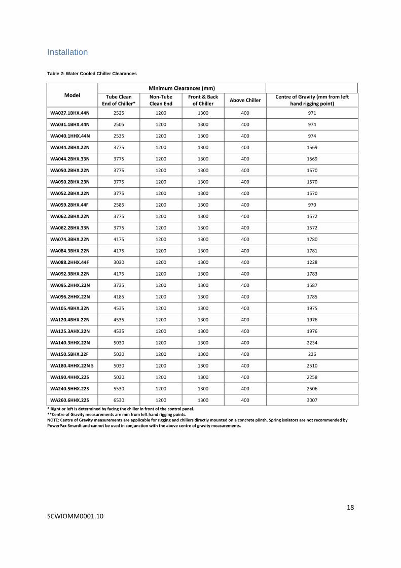
Table 2: Water Cooled Chiller Clearances
Model Minimum Clearances (mm)
Tube Clean End of Chiller*
Non‐Tube Clean End
Front & Back of Chiller
Above Chiller Centre of Gravity (mm from left
hand rigging point)
WA027.1BHX.44N 2525 1200 1300 400 971
WA031.1BHX.44N 2505 1200 1300 400 974
WA040.1HHX.44N 2535 1200 1300 400 974
WA044.2BHX.22N 3775 1200 1300 400 1569
WA044.2BHX.33N 3775 1200 1300 400 1569
WA050.2BHX.22N 3775 1200 1300 400 1570
WA050.2BHX.23N 3775 1200 1300 400 1570
WA052.2BHX.22N 3775 1200 1300 400 1570
WA059.2BHX.44F 2585 1200 1300 400 970
WA062.2BHX.22N 3775 1200 1300 400 1572
WA062.2BHX.33N 3775 1200 1300 400 1572
WA074.3BHX.22N 4175 1200 1300 400 1780
WA084.3BHX.22N 4175 1200 1300 400 1781
WA088.2HHX.44F 3030 1200 1300 400 1228
WA092.3BHX.22N 4175 1200 1300 400 1783
WA095.2HHX.22N 3735 1200 1300 400 1587
WA096.2HHX.22N 4185 1200 1300 400 1785
WA105.4BHX.32N 4535 1200 1300 400 1975
WA120.4BHX.22N 4535 1200 1300 400 1976
WA125.3AHX.22N 4535 1200 1300 400 1976
WA140.3HHX.22N 5030 1200 1300 400 2234
WA150.5BHX.22F 5030 1200 1300 400 226
WA180.4HHX.22N S 5030 1200 1300 400 2510
WA190.4HHX.22S 5030 1200 1300 400 2258
WA240.5HHX.22S 5530 1200 1300 400 2506
WA260.6HHX.22S 6530 1200 1300 400 3007
* Right or left is determined by facing the chiller in front of the control panel. **Centre of Gravity measurements are mm from left hand rigging points. NOTE: Centre of Gravity measurements are applicable for rigging and chillers directly mounted on a concrete plinth. Spring isolators are not recommended by PowerPax‐Smardt and cannot be used in conjunction with the above centre of gravity measurements.

Installation
19 SCWIOMM0001.10
Rigging Requirements Care must be exercised at all times when rigging or handling the new chiller to protect it from damage. Where possible, all packaging and protection should be left in place until the chiller is in its final position. Care should be taken to ensure that slings do not damage the compressors or control cabinets. Four rigging points (two at each end) are provided on the evaporator tube sheet corners. The chiller’s centre of gravity must be considered when rigging to ensure that the chiller is secure and balanced when suspended. A spreader bar / I‐beam combination should be used to safely position the chiller into its final location. When lifting the unit always ensure that the slings are of the correct lifting capacity. The PowerPax‐Smardt units should not be lifted from any points other than the lifting points on the tube sheet corners. PowerPax‐Smardt is not responsible for the rigging and placement of the unit. PowerPax‐Smardt strongly recommends that a specialized company unloads the machine. Local codes and regulations regarding the lifting of this equipment may apply. Always ensure that these codes are adhered to.
The rigging details are shown below in Figure 5: Rigging Diagram. Refer to Table 2: Water Cooled Chiller Clearances on page 18 for the Centre of Gravity information. Figure 5: Rigging Diagram

Installation
20 SCWIOMM0001.10
Dimensional Drawings
Figure 6: Dimensional Drawing WA027.1BHX.44N.
Figure 7: Dimensional Drawing WA031.1BHX.44N

Installation
21 SCWIOMM0001.10
Figure 8: Dimensional Drawing WA040.1HHX.44N
Figure 9: Dimensional Drawing WA044.2BHX.22N & WA044.2BHX.33N

Installation
22 SCWIOMM0001.10
Figure 10: Dimensional Drawing WA050.2BHX.22N & WA050.2BHX.23N
Figure 11 Dimensional Drawing WA052.2BHX.22N

Installation
23 SCWIOMM0001.10
Figure 12: Dimensional Drawing WA059.2BHX.44N
Figure 13: Dimensional Drawing WA062.2BHX.22N & WA062.2BHX.23N

Installation
24 SCWIOMM0001.10
Figure 14: Dimensional Drawing WA074.3BHX.22N
Figure 15: Dimensional Drawing WA084.3BHX.22N

Installation
25 SCWIOMM0001.10
Figure 16: Dimensional Drawing WA088.2HHX.44N
Figure 17: Dimensional Drawing WA092.3BHX.22N

Installation
26 SCWIOMM0001.10
Figure 18: Dimensional Drawing WA095.2HHX.22N
Figure 19: Dimensional Drawing WA096.2HHX.22N

Installation
27 SCWIOMM0001.10
Figure 20: Dimensional Drawing WA105.4BHX.32N
Figure 21: Dimensional Drawing WA120.4BHX.22N

Installation
28 SCWIOMM0001.10
Figure 22: Dimensional Drawing WA125.3AHX.22N
Figure 23: Dimensional Drawing WA140.3HHX.22N

Installation
29 SCWIOMM0001.10
Figure 24: Dimensional Drawing WA150.5BHX.22F
Figure 25: Dimensional Drawing WA180.4HHX.22NS

Installation
30 SCWIOMM0001.10
Figure 26: Dimensional Drawing WA190.4HHX.22S
Figure 27: Dimensional Drawing WA240.5HHX.22S

Installation
31 SCWIOMM0001.10
Figure 28: Dimensional Drawing WA260.6HHX.22S
Note: Above are the typical dimensional drawings for PowerPax‐Smardt chillers. Due to PowerPax‐Smardt policy of continuous development dimensions are subject to change without notice. Please contact PowerPax‐Smardt for specific dimensions.

Installation
32 SCWIOMM0001.10
Piping Configurations and Flow Connections
The evaporator and condenser have Victaulic Type stubs (unless specified as flanged) for connection to the
external water circuits.
All external piping must be adequately supported and aligned to prevent strain and distortion on the chiller
headers and couplings. See Table 3 for piping connections and typical flow configurations. Please consult the
specific chillers specification sheet for exact Flows and Pressure Drops.
Table 3: Evaporator Piping Connections and Flow Configurations
Model Nominal Capacity (kWr)
Evaporator Condenser
No. of Passes Flow Rate (l/s)* Size (inch vict.) No. of Passes Flow Rate (l/s)* Size (inch vict.)
WA027.1BHX.44N 270 4 11.6 4 4 14.6 4
WA031.1BHX.44N 280 4 12 4 4 15.1 4
WA040.1HHX.44N 400 4 17.2 5 4 21.6 5
WA044.2BHX.22N 440 2 18.9 5 2 23.8 5
WA044.2BHX.33N 440 3 18.9 5 3 23.8 5
WA050.2BHX.22N 500 2 21.5 5 2 27 5
WA050.2BHX.23N 470 2 20.2 5 3 25.4 5
WA052.2BHX.22N 520 2 22.4 5 2 28.1 5
WA059.2BHX.44F 590 4 25.4 5 4 31.9 5
WA062.2BHX.22N 619 2 26.6 6 2 33.4 6
WA062.2BHX.33N 610 3 26.2 6 3 32.9 6
WA074.3BHX.22N 740 2 31.8 6 2 40.0 6
WA084.3BHX.22N 840 2 36.1 6 2 45.4 6
WA088.2HHX.44F 880 4 37.8 8 4 47.5 8
WA092.3BHX.22N 860 2 37.0 6 2 46.4 6
WA095.2HHX.22N 950 2 40.7 6 2 51.3 6
WA096.2HHX.22N 960 2 41.3 8 2 51.8 6
WA105.4BHX.32N 990 2 42.6 6 2 53.5 6
WA120.4BHX.22N 999 2 43 8 2 53.9 6
WA125.3AHX.22N 1245 2 53.5 8 2 67.2 6
WA140.3HHX.22N 1400 2 60.2 8 2 75.6 6
WA150.5BHX.22F 1200 2 51.6 8 2 64.8 6
WA180.4HHX.22NS 1800 2 77.4 8 2 97.2 8
WA190.4HHX.22S 1840 2 50.9 8 2 99.4 8
WA240.5HHX.22S 2400 2 103.2 8 2 129.6 8
WA260.6HHX.22S 2600 2 111.8 10 2 140.4 8 *Based on ARI Standard Temperature Design

Installation
33 SCWIOMM0001.10
Minimum Water Loop Volumes
In the evaporator and condenser water circuits there is a minimum water volume requirement of 3.5 litres per
cooling kilowatt (kWr) for all air conditioning applications and 7 litres per cooling kilowatt (kWr) for all process
cooling applications. Non‐comfort cooling applications should be checked for recommended loop volume with
[email protected]. Recommendations are available from our office for placement of peripheral items
including chilled water bypass and inertia tank systems.
Evaporator Water Circuits
The chiller performance and efficiency can be adversely affected by contaminants in the water circuit. Such
contaminants may impede or block the flow of water
through the circuit or reduce heat exchanger
performance.
Strainers should be located on the inlet side of the
evaporator. Return water to the chiller must be
connected to the lower connection of the evaporator.
All external water piping must be cleaned or flushed
before being connected to the chiller set.
The water circuits should be arranged so that the
pumps discharge through the evaporator, and should
be controlled as necessary to maintain essentially
constant chiller water flows through the unit at all
load conditions.
Flow Detection Devices Flow switches or pressure differential switches are required to be fitted in the evaporator and condenser water
piping. These switches must be wired into the chiller controller in order to shut down the chiller in the event of
reduced or no flow to guard the evaporator from the potential of freezing. If flow detection devices are not
installed, warranty on the chiller will be void. An interlock from a pump is not sufficient as a safety device. These
switches should be adjusted to open and therefore shut down the chiller when the flow decreases to below 70% of
design flow (l/s) or 50% of the design pressure drop (KPa).
If the chiller has been designed for Variable Chilled Water flow, or variable condenser water flow, please confirm
the appropriate cut off point with PowerPax‐Smardt.
Figure 29: Water Circuits
Installation
34 SCWIOMM0001.10
Relief Valves
As a precaution and to meet safety code requirements each PowerPax‐Smardt water cooled chiller comes with
pressure relief valves fitted to both the evaporator and condenser vessels to relieve excess refrigerant pressure to
the atmosphere in case of equipment malfunction. Most codes require that pressure relief valves be vented to the
outside of a building to prevent oxygen displacement which can lead to asphyxiation. At least two valves on each
vessel are provided, with a change over manifold for service.
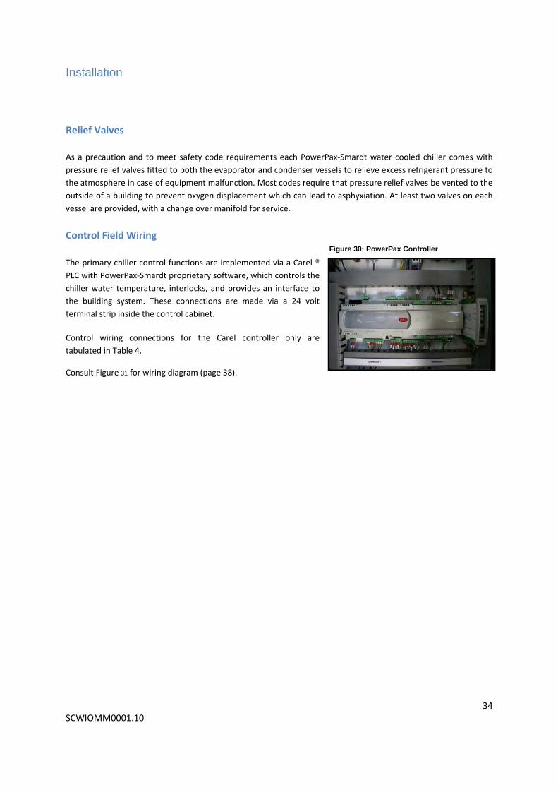
Control Field Wiring
The primary chiller control functions are implemented via a Carel ®
PLC with PowerPax‐Smardt proprietary software, which controls the
chiller water temperature, interlocks, and provides an interface to
the building system. These connections are made via a 24 volt
terminal strip inside the control cabinet.
Control wiring connections for the Carel controller only are
tabulated in Table 4.
Consult Figure 31 for wiring diagram (page 38).
Figure 30: PowerPax Controller

Installation
35 SCWIOMM0001.10
Table 4: Wiring Connections for the Carel Controller
Field Terminal Reference Signal Function
T3 24VAC Supply Supply for X2 – X8
X2
Use voltage free contacts to switch the 24 VAC at T3 to these inputs **DO NOT USE OTHER VOLTAGES**
Close to run Start/Stop
X4 Close to run Chilled Water Flow Interlock
X6 Close to run Condenser Water Flow Interlock
X8
Open to initiate Refrigerant Reclaim. (Not in use unless selected within the Software)
Refrigerant Leak Detector Interlock
X10 Run Signal ‐ Reference to X11
Voltage free relay contacts switched by the chiller controller
Closed to signal run
X11 Common Reference for X10 & X12 Reference for X10 & X12
X12 Fault Signal ‐ Reference to X11 Closed to signal fault
X14 External Set Point Offset 0 – 10 VCD SP offset from BAS
X16 Ground Ground for X14
X18 External Demand Limit Signal Signal 0 – 10 VDC External demand limit signal
X20 Ground Ground for X18
Power Wiring
Note: Control wiring must be run separately to power wiring

Installation
36 SCWIOMM0001.10
Disconnects and Power Wiring Mains wiring is brought to a single connection point. All power wiring upstream of this point is the responsibility of
the installing contractor. Ensure that a qualified electrician is used at all times.
WARNING!
To prevent injury or death, disconnect and isolate all electrical power sources before completing wiring connections to the unit. Wait at least 15 minutes after isolating power before removing compressor access covers.
The mains power supply is brought into the power cabinet from either the top or the bottom of the cabinet and is
connected to the mains bus bars. Correct Phase rotation should be observed. A dedicated Earth / Ground must
also be connected to the ground bus bar inside this same cabinet.
All wiring must be installed in accordance with appropriate local and national electrical codes and will require a
circuit breaker or fuses to protect main wiring from the final distribution sub board to the unit.
It is important that the voltage to the PowerPax‐Smardt units is within +/‐10% of the nameplate voltage, and the
voltage unbalance between phases must not exceed 2%. Any imbalance between phase voltage of more than 2%
or more than 10% of the current will be considered neglect and will void the PowerPax‐Smardt chiller warranty. If
this occurs, contact your local electricity supplier and ensure that the chiller is turned off until this has been
rectified.
To prevent control malfunctions, do not run low voltage wiring (<30V) in conduit with conductors carrying more
than 30 volts. It is recommended that the control wiring is run in screened cable and grounded as it enters the
control panel. The supply wiring should carry 3 phase + earth + neutral (for control purposes.)
Table 5: Chiller Electrical Data on the following page contains the PowerPax‐Smardt chiller electrical data. Table 6 outlines the lug sizes.

Installation
37 SCWIOMM0001.10
Table 5: Chiller Electrical Data
Model Voltage Hz kW Input FLA** LRA***
WA027.1BHX.44N 400 50 47 100 110
WA031.1BHX.44N 400 50 51 100 110
WA040.1HHX.44N 400 50 68 135 145
WA044.2BHX.22N 400 50 75 200 210
WA044.2BHX.33N 400 50 73 200 210
WA050.2BHX.22N 400 50 87 200 210
WA050.2BHX.23N 400 50 80 200 210
WA052.2BHX.22N 400 50 92 200 210
WA059.2BHX.44F 400 50 108 200 210
WA062.2BHX.22N 400 50 116 200 210
WA062.2BHX.33N 400 50 111 200 210
WA074.3BHX.22N 400 50 129 300 320
WA084.3BHX.22N 400 50 151 300 320
WA088.2HHX.44F 400 50 146 270 280
WA092.3BHX.22N 400 50 155 300 320
WA095.2HHX.22N 400 50 163 300 315
WA096.2HHX.22N 400 50 164 300 315
WA105.4BHX.32N 400 50 164 400 420
WA120.4BHX.22N 400 50 171 400 420
WA125.3AHX.22N 400 50 204 405 425
WA140.3HHX.22N 400 50 231 405 425
WA150.5BHX.22F 400 50 201 500 520
WA180.4HHX.22NS 400 50 301 540 560
WA190.4HHX.22S 400 50 313 540 560
WA240.5HHX.22S 400 50 406 750 780
WA260.6HHX.22S 400 50 412 810 830 **FLA: Nominal Full Load Amps ***LRA: Locked Rotor Amps
Table 6: Lug Sizes
Actives Neutral Earth
Main Lug Size 10mm 10mm 8mm
Note: Amp values shown above are the maximum. Refer to PowerPax for specific product values.
Compressor motors are designed to operate satisfactorily over a range of +/- 10% of the design voltage.
Note: A neutral is required for control purposes. The load is essentially a balanced 3 phase load and the
neutral may be run in the minimum allowable cable size relative to the 3 phase mains.

Installation
38 SCWIOMM0001.10
Circuit Breakers The chiller is equipped with a circuit breaker for each compressor. Isolating these circuit breakers does not isolate the incoming power supplied to the chiller. To conduct any work involving accessing the circuit breakers or the incoming power connections to the chiller, power must be isolated and tagged as per local regulations and safe work practices at the Mechanical Services board supplying the chiller.
Line Reactor / RFI Filters PowerPax‐Smardt supply each chiller with a line reactor and RFI filter per compressor as standard. These come pre‐wired from the factory. They are located in the separate panel on the chiller electrically between the circuit breakers and the compressor. The use of the line reactor and RFI filter help improve the power quality going to the compressors.
Wiring Diagram & Schematic Figure 31: Wiring Diagram

Installation
39 SCWIOMM0001.10
Note: To see Figure 32 in more detail please refer to Appendix 2.
Pre‐Commissioning PowerPax‐Smardt requires equipment to be commissioned according to a detailed procedure and by a PowerPax‐Smardt trained and certified technician. In order to activate the warranty, the commissioning form must be completed and submitted to PowerPax‐Smardt. Prior to commissioning, obtain the current pre‐commissioning form (example shown on the following pages) either by contacting the PowerPax‐Smardt service department or by downloading the form at www.powerpax.com.au and ensure that all requirements have been met to commission the Chiller. Please allow 7 days for the coordination of commissioning from the date the pre‐commissioning form is submitted. Forms can be submitted to: [email protected] or by faxing +61 3 9761 6707.
Figure 32: Wiring Schematic

Installation
40 SCWIOMM0001.10

Installation
41 SCWIOMM0001.10

Maintenance
42 SCGWCIOMM0001.10
This page is intentionally blank.

Maintenance
43 SCGWCIOMM0001.10
PowerPax‐Smardt Operation Manual

Maintenance
44 SCGWCIOMM0001.10
Operation
System Checks Before Start Up
Chiller Checks
Before powering up the PowerPax‐Smardt chiller, check for any signs of damage. If damage is discovered, contact
PowerPax‐Smardt immediately to report it.
Ensure that all refrigerant valves are open including suction, discharge, motor cooling and liquid line valves.
Electrical Checks:
Check all control connections in control cabinet. Check the wiring diagram for control wiring.
Check all mains electrical connections. Ensure that there is a neutral and an earth present and both have been
connected to the appropriate bus bar in the electrical cabinet as these are essential for correct operation of the
unit. Tighten terminals if needed.
Remove the line reactor enclosure covers and check electrical connections for tightness. Replace line reactor
enclosure covers.
Compressor Checks:
Remove the top cover from the compressor, remove the four screws, near the motor bus bars, holding the
softstart board in place. Turn the softstart over and check the four fuses are securely in place and in good working
order (See Figure 33 on the following page for softstart fuse locations).
Note: The below checks must be performed with the power OFF. Removal of covers with power applied will result in exposure to high voltages. Failure to have power off may result in electrocution.
Note: Below checks must be performed with the power OFF. Removal of covers with power applied
will result in exposure to high voltages. Failure to have power off may result in electrocution.

Maintenance
45 SCGWCIOMM0001.10
Figure 33: Softstart Fuse Locations
Check all screws for tightness and check all electrical plugs are fitted correctly. Refit top cover when all checks have
been completed.
Remove the side covers from the compressors and check the Serial Driver and BMCC boards are firmly seated onto
the backplane board (see Figure 34), check all electrical plugs are fitted correctly. Refit the compressor side covers
once the compressor tests have been completed.
Figure 34: Backplane Board

Maintenance
46 SCGWCIOMM0001.10
Powering up Compressors Check with the electrical contractor and request that power be turned on to the chiller. Once all the covers have
been replaced on the compressor, and the electrician has turned on the power, power can be turned on to the
compressors.
Compressors should be powered up one at a time. Compressors are turned on by switching the allocated circuit
breaker.
WARNING: Risk of Electrocution. Do NOT power up compressors with the compressor top covers
removed.

Maintenance
47 SCGWCIOMM0001.10
PowerPax‐Smardt Controller
Data on the Color Touch Screen Display
Information:
Entering and Leaving Chilled water temperature
Entering and Leaving Condenser water temperature
Compressor RPM
Demand percentage for each compressor
Common system low and high pressure
System status (various descriptions)
Current alarms (announce and manual reset provision) Settings:
Chiller water setpoint
Time (real time clock) – set to time stamp alarm events
PID terms
Low load offset settings
HP and LP Fault Settings
Head pressure control settings
Figure 35: Carel Controller Screen Diagram

Maintenance
48 SCGWCIOMM0001.10
Inputs, Outputs, & Interlocks
Controller BAS Interface
Table 7: Wiring Connections for the Carel Controller 2
Field Terminal Reference Signal Function
T3 24VAC Supply Supply for X2 – X8
X2
Use voltage free contacts to switch the 24 VAC at T3 to these inputs **DO NOT USE OTHER VOLTAGES**
Close to run Start/stop
X4 Close to run Chilled Water Flow Interlock
X6 Close to run Condenser Water Flow Interlock
X8
Open to initiate Refrigerant Reclaim. (Not in use unless selected within the Software)
Refrigerant Leak Detector Interlock
X10 Run Signal ‐ Reference to X11
Voltage free relay contacts switched by the chiller controller
Closed to signal run
X11 Common Reference for X10 & X12 Reference for X10 & X12
X12 Fault Signal ‐ Reference to X11 Closed to signal fault
X14 External Set Point Offset 0 – 10 VCD SP offset from BAS
X16 Ground Ground for X14
X18 External Demand Limit Signal 0 – 10 VDC External demand limit signal
X20 Ground Ground for X18

Maintenance
49 SCGWCIOMM0001.10
Figure 36: Wiring Diagram 2
Note: Because of PowerPax‐Smardt’s continual development policy and the variances in chiller models wiring schematics are likely to change. Please contact
PowerPax‐Smardt for job‐specific wiring schematics.
The PowerPax‐Smardt controller has the following inputs:
Remote on/off switch (Cooling call)
Evaporator water flow switch
Condenser water flow switch
Refrigerant Leak Detector Interlock (activated by software)
Analog chiller water set‐point offset (0 – 10 vdc at B6)
Analog demand from BAS (0 – 10 vdc at B6) – external demand should must be selected in lieu of input PI
(configurable within software but not recommended)
Digital input to hold compressor N and higher offline (N is selectable)
Analog (0 ~ 10 vdc) input to set maximum demand from the BAS
All of the above inputs will enable/disable the controller. Refer to the electrical schematics for correct
input configuration. Digital inputs that are not used should be bridged.

Maintenance
50 SCGWCIOMM0001.10
The PowerPax‐Smardt controller has the following inbuilt outputs:
Chilled water pump contacts (close if ON and cooling cool _ID‐1&ID‐4). Output contacts are (J22‐NO 17)
Condenser water pump contacts (closed with compressor run)
Alarm changeover contacts announce alarm state not reset or loss of control power
Analog (0~10 VDC) = 0 ~100% demand (at Y5)
Analog (0 ~ 10 VDC) for head pressure control by VSD (at Y6)
Head Pressure Control Option
The PowerPax‐Smardt Carel Controller is equipped with built in Head Pressure control, available via High Level
Interface, or via an analogue output (0 ‐ 10 VDC) connected to Y5 or Y6 (configured during commissioning).
The analogue output is only available providing there are four or less compressors on the chiller; however the high level output (BAS Communications) is always available. This control is not designed to optimise the plant efficiency, and should not be utilised as such, as the chiller is not monitoring sufficient data points such as the relative humidity to make such decisions. The primary purpose of this output is to optimise the condenser water temperatures to be suitable for the demands of the chiller, such as in startup, and low load conditions. This is achieved through the proportional control of a valve or similar mechanism to affecting the head pressure. The following items could be controlled by this output. Variable Speed Cooling Tower Fan Cooling Tower Bypass Valve Variable Speed Condenser Water Pump This should be configured during chiller commissioning by a PowerPax‐Smardt technician, or by a PowerPax‐
Smardt certified Service Provider..
Summary of Status Contacts
The PowerPax‐Smardt controller provides a set of change over contacts which sends a signal to the external BAS
indicating that either a fault condition is in existence (X12‐X11) or that the chiller is running (X10‐X11), however
only one condition can be indicated at any one time. The X12 contact is closed to indicate the power is off (there is
no control power to the Carel controller) or that there is a fault requiring a manual reset. These contacts close on
shunt trip, high pressure or low pressure trip (both of which require the fault to be manually reset). The Fault
contact will also close if the auto‐reset alarm count has been reached, or if a compressor fault has not auto‐reset
within the designated time, which therefore could result in the available compressors on the chiller continuing to
run despite the run status contact opening. E.g. On a 3 compressor chiller, if one compressor cannot be reset, the
fault signal will close, opening the run status, however the other 2 compressors will continue to run until the
cooling call is removed from the chiller.

Maintenance
51 SCGWCIOMM0001.10
High Level Options
ModBUS**
A ModBUS interface is available with the controller, acting as a slave. This interface is a Modicon standard RTU
protocol and has access to all basic controller information and settings.
BACnet**
BACnet over IP is available. This interface is BACnet Test Laboratory certified for BACnet protocol communications.
Remote Monitoring**
A remote access capability is available for the PowerPax‐Smardt chillers’ which enables users to access a chiller
operation summary screen utilizing a standard PC web browser.
** All of the above high level options do not come as standard on the chiller but are available for purchase at the
time the chiller is ordered. Some conditions apply to availability. Contact PowerPax‐Smardt for high level interface
options and availability.

Maintenance
52 SCGWCIOMM0001.10
Operating the Controller
Power Button
Press the Power button to display the systems ON/OFF screen. Touch the icon on the screen or press the ON/OFF
key again to locally switch the chiller either on or off.
Password Access
The controller has different levels of access that are password protected:
Open (user) Level Access
This level of access is not password protected. It provides basic information on the chillers operation and enables
the user to access basic control settings.
Level 1 – Service Access
This level of access required a level 1 password. This password allows access to more detailed chiller settings.
Level 2 – Advanced Service Access
The level of access requires a level 2 password. It allows basic unit settings such as the number of compressors and
type of unit to be changed. It is only applicable to people who have received PowerPax‐Smardt Certified Training.
Navigating the Controller
The touch screen interface uses a combination of touch features and the keys at the right hand side of the screen
to move around the controller and enter values.
Each touch screen has navigation buttons in the top corners. The following are used to move between screens:
NEXT – Go to the next screen
BACK – Return to the front screen
MENU – Go to menu options
OEM – Same as NEXT if OEM access is granted
HELP – Instructions on use
Data Entry
To navigate to the desired value, touch on the screen location or use the ENTER key. The values are changed on the controller by using the UP or DOWN arrows (keys) to the right hand side of the screen. To make a selection press the ENTER key to confirm a selection or exit the screen.
Alarm Button
An alarm condition brings up the red LED on the left hand side of the display and sounds the alarm that something is in fault. The alarm key accesses the alarm screens to display the detail of the alarms and allows a manual reset. It also switches the alarm sound off but the LED remains illuminated until the alarm reset is complete.

Maintenance
53 SCGWCIOMM0001.10
Carel Controller User Level Screens
Front User Screen
Figure 37 shows the front user screen of the Carel Controller. This main screen can be viewed at any time by pressing the ESC key. This is an overview of the systems main parameters, such as the Setpoint, the Return Chilled Water Temperature, Leaving Chilled Water Temperature, the Return Condenser Water Temperature, and Leaving Condenser Water Temperature in addition to the System Demand and the Suction and Discharge Pressures. The top line (displayed as “System on Auto”) provides further information. It may display one of the following messages, however only one message is possible at any time:
“System On Auto” – The chiller is in its normal operating state. (“‐ALARM” if there is an alarm present)
“Remote OFF (or Internal time clock)” ‐ No input on X2 detected or the time clock has the chiller OFF
“Refrigerant Leak” – This is a response to an optional external signal which Initiates a refrigerant leak response if the chiller is configured for pump‐out.
“No Evaporator Flow” – the interlock from the evaporator flow switch is open, or the flow rate is too high.
“No Condenser Flow” – the interlock from the condenser flow switch is open, or the flow rate is too high.
“Keypad OFF (or Hi Water Temp Al)” – the chiller has been turned off using this screen, (or the water temperatures are above 50C)
“OFF Cycle Delay” ‐ Minimum off timer is running (default of 180seconds)
“Manual Demand” ‐ Service intervention ‐ manual control
“Auto Reset Delay” – the controller is counting down to automatically reset the compressor fault.
“Below Restart Temp or Ambient T lockout” ‐ Return chilled water or ambient temperature too low
“Stage Delay” ‐ Inter‐stage timer delaying the next compressor start.
“HP Fault” – Condenser Pressure too high (system 1 if twin system)
“LP Fault” – Evaporator Pressure too low (system 1 if twin system)
“Freeze Alarm” ‐ Leaving Chilled Water Temperature was below the anti‐freeze set point
“LCWT Sensor Fault” ‐ Controller has detected a bad reading in the Leaving Chilled Water Temp Sensor
“Assisting Start” ‐ A compressor is about to start after the system has done a Pressure Ratio adjustment
“Bad MB Compressors” ‐ If using the optional ModBus control of compressors, and the data is interrupted between the compressors and controller this will cause a resettable fault.
“Wait Compressors” ‐ Waiting at start for compressors to be ready (normally seen after power off)
Figure 37: Front User Screen

Maintenance
54 SCGWCIOMM0001.10
Main Menu
Users have access to screens/sub menus under the heading shown on the screen in white. Figure 38 below shows the screens that users have access to under User Level Settings. For details on the access screens see the following.
Operational Data This screen provides the current set point information being utilized by the controller (see Figure 39).
Ent ChWT – this is the current entering Chilled Water Temp.
Start Temp – the temperature of leaving chilled water needed to restart system.
Low Load Offset – this is the effect on the setpoint during low load conditions.
External Offset – this shows any offset to the setpoint from the BAS signal.
Actual SP – the user defined setpoint.
Act controller value – the setpoint that includes the current external and low load offsets.
PID Out % ‐ the current demand being generated based on the setpoint and current conditions.
Demand % ‐ the actual demand, based on all limits, timers, staging etc.
Limited by ramp to – reflects the maximum system demand during start‐up due to the ramp settings.
Reset due to HP – the demand is reduced by this amount if discharge/condenser pressure exceeds pre‐determined values.
Reset due to Power – the reduction in demand limit due to excessively high current draw.
Min. Off time – time remaining to restart compressors after chiller has shut down.
Stage delay – time remaining in stage delay before next compressor loads.
Figure 38: Main Menu Screen
Figure 39: Operational Summary Screen

Maintenance
55 SCGWCIOMM0001.10
Figure 40 and Figure 41 display information for each individual compressors on the chiller such as hours, starts, and any delays or timers. This screen is repeated for each compressor present.
Figure 40: Compressor 1 Data Screen
Figure 41: Compressor 2 Data Screen

Maintenance
56 SCGWCIOMM0001.10
The Data System Electrical Screen, shown above in Figure 42, provides the information being read and calculated by the compressors only. As such it should be used as a guide only, as it is a calculated value not a measured value.
User Settings The user settings menu screen, shown below in Figure 43 allows the user to start or stop the chiller and adjust the current setpoint.
Figure 42: Data System Electrical Screen
Figure 43: User Settings Menu

Maintenance
57 SCGWCIOMM0001.10
Compressor MB Data The following screens are for information purposes only. They reflect the high level data that is being obtained from the individual compressors.
The compressor alarms and faults screen (Figure 44) shows any alarms or fault codes recorded by the compressors.
Figure 45 shows data from the compressors such as pressures, operational data, and compressor operating
speeds.
Figure 44: Compressor Alarms and Faults Screen
Figure 45: MB Data Summary Screen

Maintenance
58 SCGWCIOMM0001.10
Figure 46: Compressor Status Codes Screen
The Compressor Status Codes Screen in Figure 46 indicates the compressor status. Note: “Calibration Mode” as seen above, indicates no compressor communications.
Clock The Clock Menu Screen shown in Figure 47 displays the current time and date at the top of the screen. They can be adjusted at this screen. For installations without the building system capability to run the chiller at preset times on selected days, a basic start/stop 7 day time clock is available for this function.
Figure 47: Clock Menu

Maintenance
59 SCGWCIOMM0001.10
History Figure 48: Evaporator Temperatures Screen
Figure 49: Condenser Temperature History Screen

Maintenance
60 SCGWCIOMM0001.10
Figure 50: Graphs Help Screen
The graphs above may need to be rescaled to the appropriate range. If so, press which will change the buttons
displayed along the bottom of the screen. Select the appropriate button to scale either the temperature or time
axis, then touch the screen on the graph area. Once you have adjusted the scale, press to return to the PAN
menu, which will then allow you, using the buttons, to adjust the graph to the desired location.
Information This screen displays the Basic system setup and the software version. To access a higher user level, enter the password at this screen.
Figure 51: Information Menu

Maintenance
61 SCGWCIOMM0001.10
This page is intentionally blank.

Maintenance
62 SCGWCIOMM0001.10
PowerPax‐Smardt Maintenance Manual
Maintenance
63 SCGWCIOMM0001.10
Maintenance The following PowerPax‐Smardt maintenance schedule is outlined on the following pages in table 8. It should be noted however, that PowerPax‐Smardt require quarterly maintenances only, however this table provides the checks based on a monthly schedule should that be your requirement. Please note that maintenance should only be carried out by a PowerPax‐Smardt certified technician. Warranty is not an excuse for not maintaining the system. Chiller warranty will only be valid if the service schedule has been adhered to. Once a scheduled maintenance has been completed PowerPax‐Smardt requires the PowerPax‐Smardt service form be returned to the service department. The PowerPax‐Smardt maintenance form can be found on pages 55 – 60 of the Maintenance Manual. For the latest maintenance form please contact the PowerPax‐Smardt service department.
Note: Maintenance should only be carried out by a PowerPax certified technician. Failure to comply will
void chiller warranty.

Maintenance
64 SCGWCIOMM0001.10
Item Task Frequency
M Q A
Electrical Checks
Check main power supply voltages
Check electrical terminals are tight
Check there are no hot spots / discoloration on power cables
Check Amperages are as per design
Electronic Inspections
Check communication cables are secure
Check pressure and temperature sensor connections are secure
Check PCB’s (printed circuit boards) are free of dust
Check there are no signs of damage / hot spots on Printed Circuit Boards
Check EXV winding resistance (do NOT disturb unless repair required)
Compressor Checks
Check IGV Assembly operating correctly
Check compressor fault log
Check calibration of pressure and temperature sensors
Check Backplane voltage test points
Check all modules and connections are secure
Compressor Refrigeration Circuit Inspections
Check all mounting bolts are secure
Check for refrigerant leaks
Check for mechanical damage
Check operating temperatures and pressures
Check that the compressor motor cooling line sight glass is full during operation
Table 8: PowerPax Maintenance Schedule

Maintenance
65 SCGWCIOMM0001.10
Chilled Water Circuit Inspection
Check for insulation damage
Check chilled water sensors are secure and installed with adequate heat transfer medium
Check water flows and pressure drops are as per design conditions
Check flow switch operation
Check for leaks
Check water strainers
Condenser Water Circuit Inspection
Check chilled water sensors are secure and installed with adequate heat transfer medium
Check water flows and pressure drops are as per design conditions
Check flow switch operation
Check for leaks
Check water strainers
Water Cooled Maintenance Form The Water Cooled Maintenance form found in this manual is for demonstration purposes only and is an example of
the form issued in Excel format. When completing the scheduled maintenance on a PowerPax‐Smardt chiller
please contact the PowerPax‐Smardt service department for the latest copy of the maintenance form.

Maintenance
66 SCGWCIOMM0001.10

Maintenance
67 SCGWCIOMM0001.10

Maintenance
68 SCGWCIOMM0001.10

Maintenance
69 SCGWCIOMM0001.10
This page is intentionally blank.

Appendix
70 SCGWCIOMM0001.10
Appendix

Appendix
71 SCGWCIOMM0001.10
Appendix 1 – Recommended Spare Parts List
Item Part Description Part No. TT300 R134a
TT400 R134a
Recommendation for Stocking
No.
Compressor Components
1.1 KIT – MODULE – SOFT START (400V)
100020‐3 Recommended 1
1.2 KIT – MODULE – BACKPLANE 100021‐1 Beneficial 1
1.3 KIT – MODULE – BEARING PWM 100022 Recommended 1
1.4 KIT‐SENSOR‐ASSEMBLY‐TEMPERATURE‐MOTOR ROTOR
100034 Beneficial 1
1.5 KIT ‐SENSOR‐PRESSURE/TEMPERATURE ‐SUCTION
100036 Recommended 1
1.6 KIT‐SENSOR‐PRESSURE/TEMPERATURE‐DISCHARGE & ECR
100037 Recommended 1
1.7 KIT ‐DC/DC CONVERTER ASSEMBLY
100040‐5 Recommended 1
1.8 KIT‐IGBT 370032, MANIFOLD COOLING
100043‐3 Beneficial – TT300 1
1.9 KIT ‐IGBT 340032 MANIFOLD COOLING ‐ TT400
100043‐4 Beneficial – TT400 1
1.10 KIT‐DIODE RECTIFIERS TT300 100047‐1 Not Required 0
1.11 KIT‐DIODE RECTIFIERS TT400 100047‐2 Not Required 0

Appendix
72 SCGWCIOMM0001.10
1.12 KIT ‐IGV HOUSING ASSEMBLY ‐TT‐300 EXTENDED RANGE (R134a)
100050‐2 Beneficial – TT300 1
1.13 KIT‐IGV ‐HOUSING ASSEMBLY AND O' RING‐TT‐400C
100050‐7 Beneficial – TT400 1
1.14 KIT – MODULE – SERIAL DRIVER 100292 Beneficial 1
1.15 KIT –COOLING VALVE ASSEMBLY – TT300
100150‐2 Beneficial – Model Specific
1
1.16 KIT –COOLING VALVE ASSEMBLY – TT400C
100150‐4 Beneficial – Model Specific
1
1.17 KIT‐FUSES (FIE) ASIC SOFT START TT300,TT400
100317‐1 Recommended 1
1.18 KIT ‐ FUSE CLASS T‐FAST ACTING A6T 175 TT300,TT400
100344 Recommended 1
1.19 KIT –BEARING MOTOR COMPRESSOR CONTROL (BMCC)
100296 Beneficial – Model Specific
1
Chiller Components
2.1 Pressure Sensor SPKT0031CO Recommended 2
2.2 Temperature Sensor NTCO30WPOO Recommended 2
2.3 PCO3 Controller PCO3000AL0 Beneficial 1
2.4 EXV Controller EXV‐Control Recommended 1
Other Components
3.1 EXV Head EXV–Head Recommended 1

Appendix
73 SCGWCIOMM0001.10
Appendix 2 – Wiring Schematic

Appendix
74 SCGWCIOMM0001.10
This page is intentionally blank.

Appendix
75 SCGWCIOMM0001.10
This page is intentionally blank.

76 SCGWCIOMM0001.10
144 Colchester Road PO Box 2021
Bayswater North, VIC Australia, 3775
www.powerpax.com.au Phone: +61 3 9761 7905 Fax: +61 3 9761 6707